design manual m 22-01 revision september 2002 · ... and surfacing materials november 1999 ......
TRANSCRIPT

Publications Transmittal
Transmittal Number Date PT 02-071
September 2002
Publication Distribution To: All English Design Manual holders Publication Title Publication Number Design Manual (English) Revision 2002-2 M 22-01 Originating Organization Environmental and Engineering Service Center, Design Office, Design Policy,
Standards, and Safety Research Unit through Engineering Publications
Remarks and Instructions
Remarks: 1. This revision is provided in English (US common) units only. The metric Design Manual is out-of-date and must not
be used with respect to the English chapters dated February 2002 or later.
2. Manual holders are reminded that the Internet is updated when a revision is printed. CDs are up-to-date at the time of production-order only. Subsequent revisions can occur in the six months between orders for new CDs.
3. The WSDOT Design Policy home page has several new features including “Contact Information.” The new What’s New “Design Manual Errata” page lists corrections for known “technical” errata and incorrect reference’s. The new Other Items “Design Manual Forms” page offers access to page iii and Chapter 140’s Managing Project Delivery Worksheet as Word documents. This will take you there: http://www.wsdot.wa.gov/eesc/design/policy/designpolicy.htm
Additional copies may be purchased from: Washington State Department of Transportation Finance and Administration Directional Documents and Engineering Publications PO BOX 47408 Olympia, WA 98504-7408
Phone: (360) 705-7430 Fax: (360) 705-6861 E-mail: [email protected]
Instructions: Page numbers and corresponding sheet-counts are given in the table below to indicate portions of the Design Manual that are to be removed and inserted to accomplish this revision.
Remove Insert Chapter Pages Sheets Pages Sheets
Foreword i-ii 1 i-ii 1 Contents & Letters List 1-24 12 1-26 13 Chapter 140 “Managing Project Delivery” (NEW) - - 1-17 9 Chapter 325 “Design Matrix Procedures” 1-2 1 1-2 1 Chapter 325 “Design Matrix Procedures” 11-15 3 11-15 3 Chapter 340 “Minor Operational Enhancement Projects” 1-11 6 1-11 6 Chapter 720 “Impact Attenuator Systems” 1-12 6 1-15 8 Chapter 940 “Traffic Interchanges” 1-34 17 1-36 18 Chapter 1020 “Bicycle Facilities” 25-26 1 25-26 1 Chapter 1120 “Bridges” 1-6 3 1-7 4 Chapter 1210 “Hydraulic Design” 1-3 2 1-3 2 Chapter 1460 “Fencing” 1-2 1 1-4 2 Index 1-17 9 1-18 9
Distributed By Phone Number Signature Directional Documents and Engineering Publications
(360) 705-7430 FAX: 705-6861


Design Manual ForewordSeptember 2002 Page i
Foreword
This Design Manual is for use by our engineering personnel. It providespolicies, procedures, and methods for developing and documenting the designof improvements to the transportation network in Washington State.The Design Manual is developed for state facilities and may not be appropriatefor all county roads or city streets that are not state highways.
The manual supplements the engineering analyses and judgment that must beapplied to improvement and preservation projects. It provides uniform proceduresfor documenting and implementing design decisions. When proposed designsmeet the requirements contained in the Design Manual, little additionaldocumentation is required.
The designer must understand that the design environment changes rapidly, andoften without warning to the practitioner. To track every change, and to makeimprovements based upon each, is not feasible. The intent of this manual is toprovide recommended values for critical dimensions. Flexibility is permitted toencourage independent design that is tailored to particular situations.When flexibility is applied, and critical dimensions of a proposed design do notmeet the Design Manual criteria, additional documentation is required to recordthe decision making process.
The fact that new or modified design criteria are added to the Design Manualthrough the revision process does not imply that existing features are deficientor inherently dangerous. Nor does it suggest or mandate immediate engineeringreview or initiation of new projects.
Cost-effective and environmentally conscious design is emphasized, andconsideration of the use of the highway corridor by transit, pedestrians, andbicyclists is included. Designers are encouraged to view the highway corridorbeyond the vehicular movement context. To accommodate multimodal use, thecriteria provided for one mode is to be appropriately adapted, as needed, at aspecific location.
The complexity of transportation design requires the designer to make fundamentaltradeoff decisions that balance competing considerations. Although weighing theseconsiderations adds to the complexity of design, it accounts for the needs of aparticular project and the relative priorities of various projects and programs.Improvements must necessarily be designed and prioritized in light of finitetransportation funding.
Updating the manual is a continuing process, and revisions are issued periodically.Questions, observations, and recommendations are invited. Page iii is provided toencourage comments and to assure their prompt delivery. For clarification of thecontent of the manual, contact the Headquarters Design Office. The e-mail addressis [email protected].
Harold Peterfeso, P.E.State Design Engineer

Foreword Design ManualPage ii September 2002
Design Manual Contents September 2002 Amendment
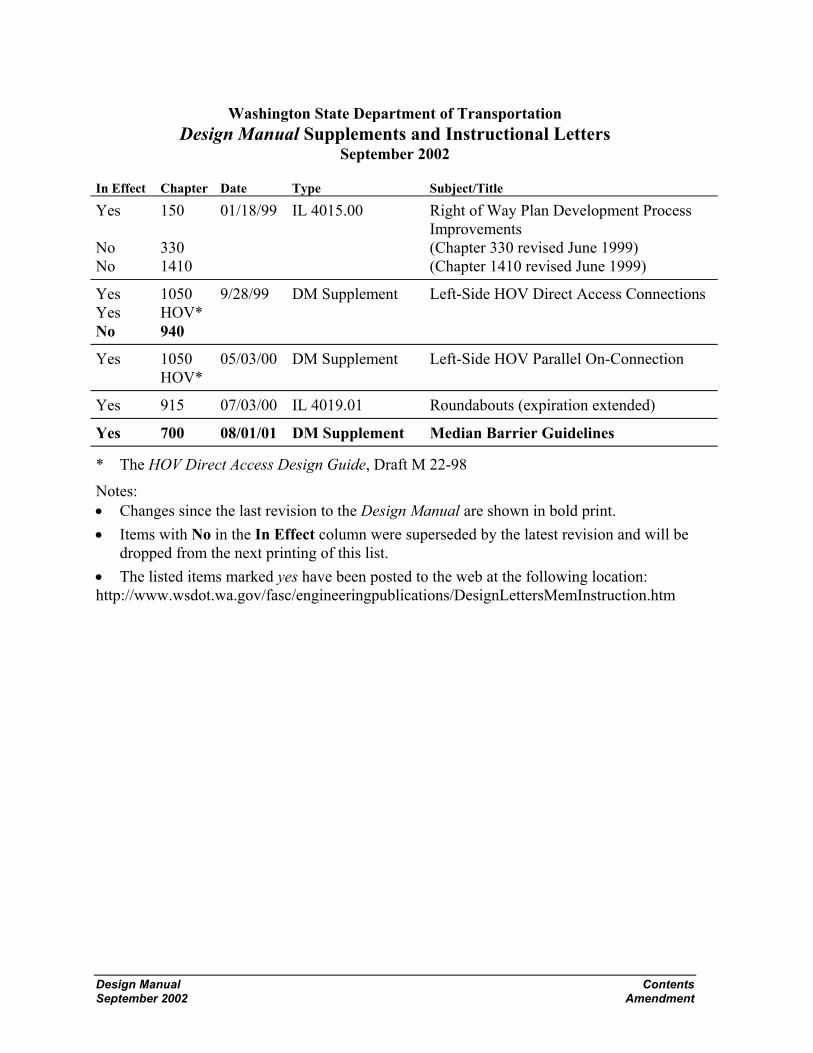
Washington State Department of Transportation Design Manual Supplements and Instructional Letters
September 2002
In Effect Chapter Date Type Subject/Title
Yes No No
150 330 1410
01/18/99 IL 4015.00 Right of Way Plan Development Process Improvements (Chapter 330 revised June 1999) (Chapter 1410 revised June 1999)
Yes Yes No
1050 HOV* 940
9/28/99 DM Supplement Left-Side HOV Direct Access Connections
Yes 1050 HOV*
05/03/00 DM Supplement Left-Side HOV Parallel On-Connection
Yes 915 07/03/00 IL 4019.01 Roundabouts (expiration extended)
Yes 700 08/01/01 DM Supplement Median Barrier Guidelines
* The HOV Direct Access Design Guide, Draft M 22-98
Notes: • Changes since the last revision to the Design Manual are shown in bold print. • Items with No in the In Effect column were superseded by the latest revision and will be
dropped from the next printing of this list. • The listed items marked yes have been posted to the web at the following location: http://www.wsdot.wa.gov/fasc/engineeringpublications/DesignLettersMemInstruction.htm


Design Manual ContentsSeptember 2002 Page 1
Contents
Date
Division 1 General Information
Chapter 120 Planning May 2000120.01 General120.02 References120.03 Definitions120.04 Legislation and Policy Development120.05 Planning at WSDOT120.06 Linking Transportation Plans120.07 Linking WSDOT Planning to Programming
Chapter 140 Managing Project Delivery September 2002140.01 General140.02 References140.03 Definitions140.04 Resources140.05 Process and Tools140.06 Responsibilities140.07 Documentation
Division 2 Hearings, Environmental, and Permits
Chapter 210 Public Involvement and Hearings December 1998210.01 General210.02 References210.03 Definitions210.04 Public Involvement210.05 Hearings210.06 Environmental Hearing210.07 Corridor Hearing210.08 Design Hearing210.09 Access Hearing210.10 Combined Hearings210.11 Administrative Appeal Hearing210.12 Documentation
Chapter 220 Project Environmental Documentation June 1989220.01 General220.02 Definitions220.03 Project Classification220.04 Class I, EIS220.05 Class II, CE220.06 Class III, EA/Checklist220.07 Project Reevaluation220.08 Project Reviews

Contents Design ManualPage 2 September 2002
Date
Chapter 240 Permits and Approvals From OtherGovernmental Agencies September 1990240.01 General (240-13 and 14 June 1989)240.02 United States Department of the Army-Corps of Engineers240.03 United States Coast Guard240.04 United States Forest Service (USFS)240.05 Federal Aviation Administration (FAA)240.06 FHWA — Western Federal Lands Highway Division (WFLHD)240.07 Federal Energy Regulatory Commission240.08 Environmental Protection Agency240.09 Washington State Departments of Fisheries and Wildlife240.10 Washington State Department of Ecology (DOE)240.11 Washington State Department of Natural Resources (DNR)240.12 Washington State Department of Labor and Industries240.13 Local Agencies240.14 Utility Agreements
Division 3 Project Documentation
Chapter 315 Value Engineering August 1998315.01 General315.02 References315.03 Definitions315.04 Procedure315.05 Documentation
Chapter 325 Design Matrix Procedures May 2001325.01 General (325-1 and 2 September 2002)325.02 Terminology (325-11 through 15 September 2002)325.03 Design Matrix Procedures (325-3, 6, 7 February 2002)325.04 Selecting a Design Matrix325.05 Project Type325.06 Using a Design Matrix
Chapter 330 Design Documentation, Approval, and Process Review May 2001330.01 General330.02 References330.03 Purpose330.04 Project Development330.05 Project Definition Phase330.06 Design Documentation330.07 Design Approval330.08 Process Review
Chapter 340 Minor Operational Enhancement Projects September 2002340.01 General340.02 References340.03 Definitions340.04 Minor Operational Enhancement Matrix Procedures340.05 Selecting a Minor Operational Enhancement Matrix

Design Manual ContentsSeptember 2002 Page 3
Date340.06 Project Type340.07 Using a Minor Operational Enhancement Matrix340.08 Project Approval340.09 Documentation
Division 4 Project Design Criteria
Chapter 410 Basic Design Level May 2001410.01 General (410-2 February 2002)410.02 Required Basic Safety Items of Work410.03 Minor Safety and Minor Preservation Work
Chapter 430 Modified Design Level May 2001430.01 General (430-10 February 2002)430.02 Design Speed430.03 Roadway Widths430.04 Ramp Lane Widths430.05 Stopping Sight Distance430.06 Profile Grades430.07 Cross Slope430.08 Fill Slopes and Ditch Inslopes430.09 Intersections430.10 Bridges430.11 Documentation
Chapter 440 Full Design Level May 2001440.01 General440.02 References440.03 Definitions440.04 Functional Classification440.05 Terrain Classification440.06 Geometric Design Data440.07 Design Speed440.08 Traffic Lanes440.09 Shoulders440.10 Medians440.11 Curbs440.12 Parking440.13 Pavement Type440.14 Structure Width440.15 Grades
Division 5 Soils and Paving
Chapter 510 Investigation of Soils, Rock, and Surfacing Materials November 1999510.01 General510.02 References510.03 Materials Sources510.04 Geotechnical Investigation, Design, and Reporting510.05 Use of Geotechnical Consultants

Contents Design ManualPage 4 September 2002
Date510.06 Geotechnical Work by Others510.07 Surfacing Report510.08 Documentation
Chapter 520 Design of Pavement Structure February 2002520.01 Introduction (520-7 through 14 April 1998)520.02 Estimating Tables
Chapter 530 Geosynthetics April 1998530.01 General (530-13 November 1999)530.02 References530.03 Geosynthetic Types and Characteristics530.04 Geosynthetic Function Definitions and Applications530.05 Design Approach for Geosynthetics530.06 Design Responsibility530.07 Documentation
Division 6 Geometrics
Chapter 610 Highway Capacity June 1989610.01 General610.02 Definitions and Symbols610.03 Design
Chapter 620 Geometric Plan Elements April 1998620.01 General (620-1 May 2001)620.02 References (620-4 November 1999)620.03 Definitions620.04 Horizontal Alignment620.05 Distribution Facilities620.06 Number of Lanes and Arrangement620.07 Pavement Transitions620.08 Procedures620.09 Documentation
Chapter 630 Geometric Profile Elements April 1998630.01 General (630-2 May 2001)630.02 References630.03 Vertical Alignment630.04 Coordination of Vertical and Horizontal Alignments630.05 Airport Clearance630.06 Railroad Crossings630.07 Procedures630.08 Documentation
Chapter 640 Geometric Cross Section February 2002640.01 General640.02 References640.03 Definitions640.04 Roadways640.05 Superelevation640.06 Medians and Outer Separations

Design Manual ContentsSeptember 2002 Page 5
Date640.07 Roadsides640.08 Roadway Sections640.09 Documentation
Chapter 650 Sight Distance April 1998650.01 General (650-3 June 1999)650.02 References (650-4 November 1999)650.03 Definitions (650-8 May 2000)650.04 Passing Sight Distance (650-9 May 2001)650.05 Stopping Sight Distance650.06 Decision Sight Distance
Division 7 Roadside Safety Elements
Chapter 700 Roadside Safety August 1997700.01 General (700-1, 2, and 5 May 2001)700.02 References (700-3 April 1998)700.03 Definitions (700-8 June 1999)700.04 Clear Zone700.05 Hazards to be Considered for Mitigation700.06 Median Considerations700.07 Other Roadside Safety Features700.08 Documentation
Chapter 710 Traffic Barriers May 2000710.01 General710.02 References710.03 Definitions710.04 Project Requirements710.05 Barrier Design710.06 Beam Guardrail710.07 Cable Barrier710.08 Concrete Barrier710.09 Special Use Barriers710.10 Redirectional Land Forms710.11 Bridge Rails710.12 Other Barriers710.13 Documentation
Chapter 720 Impact Attenuator Systems September 2002720.01 Impact Attenuator Systems720.02 Design Criteria720.03 Selection720.04 Documentation
Division 8 Traffic Safety Elements
Chapter 810 Work Zone Traffic Control February 2002810.01 General810.02 References810.03 Public Information810.04 Work Zone Classification

Contents Design ManualPage 6 September 2002
Date810.05 Work Zone Types810.06 Project Definition810.07 Work Zone Safety810.08 Regulatory Traffic Control Strategies810.09 Traffic Control Plans and Devices810.10 Documentation
Chapter 820 Signing November 1999820.01 General820.02 References820.03 Design Components820.04 Overhead Installation820.05 Mileposts820.06 Guide Sign Plan820.07 Documentation
Chapter 830 Delineation May 2000830.01 General830.02 References830.03 Pavement Markings830.04 Guide Posts830.05 Barrier Delineation830.06 Wildlife Warning Reflectors830.07 Documentation
Chapter 840 Illumination May 2000840.01 General840.02 References840.03 Definitions840.04 Required Illumination840.05 Additional Illumination840.06 Design Criteria840.07 Documentation
Chapter 850 Traffic Control Signals May 2001850.01 General850.02 References850.03 Definitions850.04 Procedures850.05 Signal Warrants850.06 Conventional Traffic Signal Design850.07 Documentation
Chapter 860 Intelligent Transportation Systems November 1999860.01 General860.02 References860.03 Traffic Data Collection860.04 Traffic Flow Control860.05 Motorist Information860.06 Documentation

Design Manual ContentsSeptember 2002 Page 7
Date
Division 9 Interchanges and Intersections
Chapter 910 Intersections at Grade May 2001910.01 General (910-1 through 3, 8, 10, 13 February 2002)910.02 References (910-23 through 25, 29, 30 February 2002)910.03 Definitions910.04 Design Considerations910.05 Design Vehicle910.06 Right-Turn Corners910.07 Channelization910.08 Roundabouts910.09 U-Turns910.10 Sight Distance at Intersections910.11 Traffic Control at Intersections910.12 Interchange Ramp Terminals910.13 Procedures910.14 Documentation
Chapter 915 Roundabouts February 2002915.01 General915.02 References915.03 Definitions915.04 Roundabout Categories915.05 Capacity Analysis915.06 Geometric Design915.07 Pedestrians915.08 Bicycles915.09 Signing and Pavement Marking915.10 Illumination915.11 Access, Parking, and Transit Facilities915.12 Procedures915.13 Documentation
Chapter 920 Road Approaches April 1998920.01 General (920-5 and 6 November 1999)920.02 References (920-8 and 9 May 2001)920.03 Definitions920.04 Design Considerations920.05 Road Approach Connection Category920.06 Road Approach Design Template920.07 Sight Distance920.08 Road Approach Spacing and Corner Clearance920.09 Drainage Requirements920.10 Procedures920.11 Documentation
Chapter 930 Railroad Grade Crossings June 1989930.01 General (930-4, 6 through 12 March 1994)930.02 References930.03 Plans930.04 Traffic Control Systems

Contents Design ManualPage 8 September 2002
Date930.05 Stopping Lanes930.06 Types of Crossing Surfaces930.07 Crossing Closure930.08 Traffic Controls During Construction and Maintenance930.09 Railroad Grade Crossing Orders930.10 Longitudinal Easements From Railroad
Chapter 940 Traffic Interchanges September 2002940-01 General940.02 References940.03 Definitions940.04 Interchange Design940.05 Ramps940.06 Interchange Connections940.07 Ramp Terminal Intersections at Crossroads940.08 Interchanges on Two-Lane Highways940.09 Interchange Plans940.10 Documentation
Chapter 960 Median Crossovers August 1997960.01 General960.02 Analysis960.03 Design960.04 Approval960.05 Documentation
Division 10 Auxiliary Facilities
Chapter 1010 Auxiliary Lanes November 19991010.01 General (1010-2 and 8 May 2001)1010.02 References1010.03 Definitions1010.04 Climbing Lanes1010.05 Passing Lanes1010.06 Slow Moving Vehicle Turnouts1010.07 Shoulder Driving for Slow Vehicles1010.08 Emergency Escape Ramps1010.09 Chain-Up Area1010.10 Documentation
Chapter 1020 Bicycle Facilities May 20011020.01 General (1020-25 and 26 September 2002)1020.02 References1020.03 Definitions1020.04 Planning1020.05 Design1020.06 Documentation
Chapter 1025 Pedestrian Design Considerations May 20011025.01 General1025.02 References1025.03 Definitions

Design Manual ContentsSeptember 2002 Page 9
Date1025.04 Policy1025.05 Pedestrian Human Factors1025.06 Pedestrian Activity Generators1025.07 Pedestrian Facility Design1025.08 Documentation
Chapter 1030 Safety Rest Areas and Traveler Services June 19991030.01 General (1030-3 through 5 November 1999)1030.02 References1030.03 Documentation
Chapter 1040 Weigh Sites May 20001040.01 General1040.02 Definitions1040.03 Planning, Development, and Responsibilities1040.04 Permanent Facilities1040.05 Portable Facilities1040.06 Shoulder Sites1040.07 Federal Participation1040.08 Procedures1040.09 Documentation
Chapter 1050 High Occupancy Vehicle Facilities June 19951050.01 General1050.02 Definitions1050.03 References1050.04 Preliminary Design and Planning1050.05 Operations1050.06 Design Criteria1050.07 Arterial HOV
Chapter 1060 Transit Benefit Facilities December 19911060.01 Introduction (1060-14 March 1994)1060.02 Definitions (1060-16 through 18 March 1994)1060.03 Park and Ride Lots (1060-19 November 1997)1060.04 Transfer/Transit Centers (1060-20 through 22 March 1994)1060.05 Bus Stops and Pullouts (1060-23 and 24 July 1994)1060.06 Passenger Amenities (1060-25 through 34 March 1994)1060.07 Roadway and Vehicle (1060-35 and 36 July 1994)
Design Criteria Characteristics (1060-37 and 38 March 1994)1060.08 Intersection Radii1060.09 Disabled Accessibility1060.10 References
Division 11 Structures
Chapter 1110 Site Data for Structures April 19981110.01 General (1110-3 through 5 November 1999)1110.02 References1110.03 Required Data for All Structures1110.04 Additional Data for Waterway Crossings1110.05 Additional Data for Grade Separations
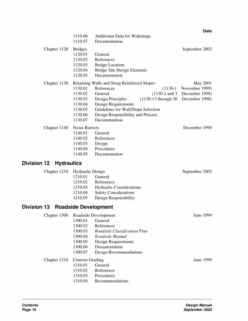
Contents Design ManualPage 10 September 2002
Date1110.06 Additional Data for Widenings1110.07 Documentation
Chapter 1120 Bridges September 20021120.01 General1120.02 References1120.03 Bridge Location1120.04 Bridge Site Design Elements1120.05 Documentation
Chapter 1130 Retaining Walls and Steep Reinforced Slopes May 20011130.01 References (1130-1 November 1999)1130.02 General (1130-2 and 3 December 1998)1130.03 Design Principles (1130-13 through 30 December 1998)1130.04 Design Requirements1130.05 Guidelines for Wall/Slope Selection1130.06 Design Responsibility and Process1130.07 Documentation
Chapter 1140 Noise Barriers December 19981140.01 General1140.02 References1140.03 Design1140.04 Procedures1140.05 Documentation
Division 12 Hydraulics
Chapter 1210 Hydraulic Design September 20021210.01 General1210.02 References1210.03 Hydraulic Considerations1210.04 Safety Considerations1210.05 Design Responsibility
Division 13 Roadside Development
Chapter 1300 Roadside Development June 19991300.01 General1300.02 References1300.03 Roadside Classification Plan1300.04 Roadside Manual1300.05 Design Requirements1300.06 Documentation1300.07 Design Recommendations
Chapter 1310 Contour Grading June 19991310.01 General1310.02 References1310.03 Procedures1310.04 Recommendations
Design Manual ContentsSeptember 2002 Page 11
Date
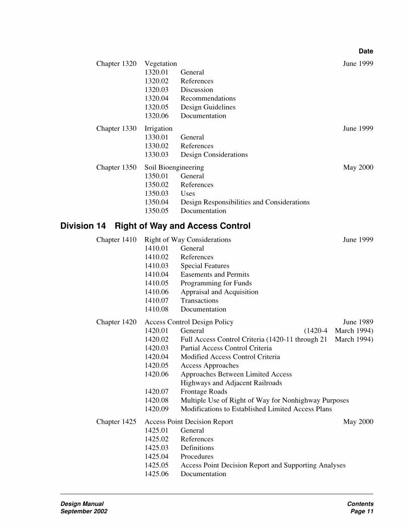
Chapter 1320 Vegetation June 19991320.01 General1320.02 References1320.03 Discussion1320.04 Recommendations1320.05 Design Guidelines1320.06 Documentation
Chapter 1330 Irrigation June 19991330.01 General1330.02 References1330.03 Design Considerations
Chapter 1350 Soil Bioengineering May 20001350.01 General1350.02 References1350.03 Uses1350.04 Design Responsibilities and Considerations1350.05 Documentation
Division 14 Right of Way and Access Control
Chapter 1410 Right of Way Considerations June 19991410.01 General1410.02 References1410.03 Special Features1410.04 Easements and Permits1410.05 Programming for Funds1410.06 Appraisal and Acquisition1410.07 Transactions1410.08 Documentation
Chapter 1420 Access Control Design Policy June 19891420.01 General (1420-4 March 1994)1420.02 Full Access Control Criteria (1420-11 through 21 March 1994)1420.03 Partial Access Control Criteria1420.04 Modified Access Control Criteria1420.05 Access Approaches1420.06 Approaches Between Limited Access
Highways and Adjacent Railroads1420.07 Frontage Roads1420.08 Multiple Use of Right of Way for Nonhighway Purposes1420.09 Modifications to Established Limited Access Plans
Chapter 1425 Access Point Decision Report May 20001425.01 General1425.02 References1425.03 Definitions1425.04 Procedures1425.05 Access Point Decision Report and Supporting Analyses1425.06 Documentation
Contents Design ManualPage 12 September 2002
Date
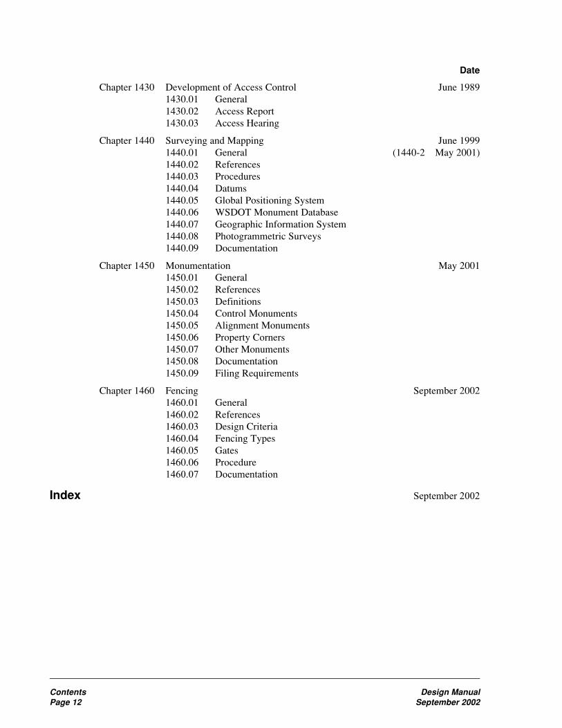
Chapter 1430 Development of Access Control June 19891430.01 General1430.02 Access Report1430.03 Access Hearing
Chapter 1440 Surveying and Mapping June 19991440.01 General (1440-2 May 2001)1440.02 References1440.03 Procedures1440.04 Datums1440.05 Global Positioning System1440.06 WSDOT Monument Database1440.07 Geographic Information System1440.08 Photogrammetric Surveys1440.09 Documentation
Chapter 1450 Monumentation May 20011450.01 General1450.02 References1450.03 Definitions1450.04 Control Monuments1450.05 Alignment Monuments1450.06 Property Corners1450.07 Other Monuments1450.08 Documentation1450.09 Filing Requirements
Chapter 1460 Fencing September 20021460.01 General1460.02 References1460.03 Design Criteria1460.04 Fencing Types1460.05 Gates1460.06 Procedure1460.07 Documentation
Index September 2002

Design Manual ContentsSeptember 2002 Page 13
Figures
FigureNumber Title Page Last Date
120-1 Planning Organizations 120-3 May 2000120-2 Transportation Plan Relationships 120-17 May 2000120-3 RTIP, MTIP, and STIP Development Process 120-18 May 2000120-4 Planning and Programming Links 120-19 May 2000140-1 Overlapping Disciplines for Successful Project Delivery 140-1 September 2002140-2 Project Management Trade-Off Triangle 140-1 September 2002140-3 Relative Effort 140-3 September 2002140-4 Managing Project Delivery Steps and Elements 140-4 September 2002140-5 Risk Probability – Impact Matrix 140-9 September 2002140-6 Change Management Form 140-15 September 2002140-7a Task Planning Worksheet 140-16 September 2002140-7b Task Planning Worksheet 140-17 September 2002
210-1 Sequence for a Hearing 210-16 December 1998220-1 Environmental Process Flow Chart 220-14 June 1989240-1a Permits and Approvals 240-11 September 1990240-1b Permits and Approvals 240-12 September 1990240-2 FAA Notice Requirement Related to Highways 240-13 June 1989240-3 DNR Area Management Units 240-14 June 1989
315-1 Eight-Phase Job Plan for VE Studies 315-5 August 1998315-2 Request for Value Engineering Study 315-6 August 1998315-3 VE Study Team Tools 315-7 August 1998325-1 Design Matrix Selection Guide 325-4 May 2001325-2a NHS Highways in Washington 325-6 February 2002325-2b NHS Highways in Washington (continued) 325-7 February 2002325-3a Preservation Program 325-8 May 2001325-3b Improvement Program 325-9 May 2001325-3c Improvement Program (continued) 325-10 May 2001325-4 Design Matrix 1 — Interstate Routes (Main Line) 325-11 September 2002325-5 Design Matrix 2 — Interstate Interchange Areas 325-12 September 2002325-6 Design Matrix 3 — NHS Routes (Main Line) 325-13 September 2002325-7 Design Matrix 4 — Non-Interstate Interchange Areas 325-14 September 2002325-8 Design Matrix 5 — Non-NHS Routes 325-15 September 2002330-1 Design Approval Level 330-7 May 2001330-2 Reviews and Approvals 330-8 May 2001330-3a Reviews and Approvals, Design 330-9 May 2001330-3b Reviews and Approvals, Design (continued) 330-10 May 2001330-4 PS&E Process Approvals 330-11 May 2001330-5a Sample Project Analysis 330-12 May 2001330-5b Sample Project Analysis 330-13 May 2001330-6 Sample Evaluate Upgrade (EU) 330-14 May 2001340-1 Minor Operational Enhancement Matrix Selection Guide 340-4 February 2002

Contents Design ManualPage 14 September 2002
340-2 Minor Operational Enhancement Matrix 1Interstate & NHS Freeway Routes 340-7 September 2002
340-3 Minor Operational Enhancement Matrix 2NHS Nonfreeway Routes 340-8 September 2002
340-4 Minor Operational Enhancement Matrix 3Non-NHS Routes 340-9 September 2002
340-5a Q Project Design Summary/Approval Template 340-10 February 2002340-5b Q Project Design Summary/Approval Template 340-11 February 2002430-1 Turning Ramp Lane Widths Modified Design Level 430-1 May 2001430-2 Design Vehicles Modified Design Level 430-3 May 2001430-3 Modified Design Level for Multilane Highways and Bridges 430-4 May 2001430-4 Modified Design Level for Two-Lane Highways and Bridges 430-5 May 2001430-5 Minimum Total Roadway Widths for Two-Lane
Highway Curves 430-6 November 1997430-6 Minimum Total Roadway Widths for Two-Lane
Highway Curves, ∆<90˚ — Modified Design Level 430-7 May 2001430-7 Evaluation for Stopping Sight Distance for Crest Vertical
Curves — Modified Design Level 430-8 May 2001430-8 Evaluation for Stopping Sight Distance for Horizontal
Curves — Modified Design Level 430-9 May 2001430-9 Main Line Roadway Sections — Modified Design Level 430-10 February 2002430-10 Ramp Roadway Sections — Modified Design Level 430-11 May 2001440-1 Desirable Design Speed 440-4 May 2001440-2 Minimum Shoulder Width 440-5 May 2001440-3 Shoulder Width for Curb 440-6 May 2001440-4 Geometric Design Data, Interstate 440-9 May 2001440-5a Geometric Design Data, Principle Arterial 440-10 May 2001440-5b Geometric Design Data, Principle Arterial 440-11 May 2001440-6a Geometric Design Data, Minor Arterial 440-12 May 2001440-6b Geometric Design Data, Minor Arterial 440-13 May 2001440-7a Geometric Design Data, Collector 440-14 May 2001440-7b Geometric Design Data, Collector 440-15 May 2001
510-1 Material Source Development Plan 510-16 November 1999520-1 Estimating — Miscellaneous Tables 520-2 February 2002520-2a Estimating — Asphalt Concrete Pavement and Asphalt
Distribution Tables 520-3 February 2002520-2b Estimating — Asphalt Concrete Pavement and Asphalt
Distribution Tables 520-4 February 2002520-3 Estimating — Bituminous Surface Treatment 520-5 February 2002520-4 Estimating — Base and Surfacing Typical Section
Formulae and Example 520-6 February 2002520-5a Estimating — Base and Surfacing Quantities 520-7 April 1998520-5b Estimating — Base and Surfacing Quantities 520-8 April 1998520-5c Estimating — Base and Surfacing Quantities 520-9 April 1998520-5d Estimating — Base and Surfacing Quantities 520-10 April 1998520-5e Estimating — Base and Surfacing Quantities 520-11 April 1998520-5f Estimating — Base and Surfacing Quantities 520-12 April 1998
FigureNumber Title Page Last Date

Design Manual ContentsSeptember 2002 Page 15
520-5g Estimating — Base and Surfacing Quantities 520-13 April 1998520-5h Estimating — Base and Surfacing Quantities 520-14 April 1998530-1 Selection Criteria for Geotextile Class 530-3 April 1998530-2 Maximum Sheet Flow Lengths for Silt Fences 530-8 April 1998530-3 Maximum Contributing Area for Ditch and
Swale Applications 530-8 April 1998530-4 Design Process for Drainage and Erosion Control
Geotextiles and Nonstandard Applications 530-12 April 1998530-5 Design Process for Separation, Soil Stabilization,
and Silt Fence 530-13 November 1999530-6a Examples of Various Geosynthetics 530-14 April 1998530-6b Examples of Various Geosynthetics 530-15 April 1998530-7a Geotextile Application Examples 530-16 April 1998530-7b Geotextile Application Examples 530-17 April 1998530-7c Geotextile Application Examples 530-18 April 1998530-7d Geotextile Application Examples 530-19 April 1998530-8 Definition of Slope Length 530-20 April 1998530-9 Definition of Ditch or Swale Storage Length
and Width 530-21 April 1998530-10 Silt Fences for Large Contributing Area 530-22 April 1998530-11 Silt Fence End Treatment 530-23 April 1998530-12 Gravel Check Dams for Silt Fences 530-24 April 1998
610-1 Type of Area and Appropriate Level of Service 610-3 June 1989610-2 Adjustment Factor for Type of Multilane Highway and
Development Environment, fE 610-3 June 1989610-3 Maximum ADT vs. Level of Service and Type of Terrain
for Two-Lane Rural Highways 610-4 June 1989610-4 Service Flow Rate per Lane (SFL) for Multilane Highways 610-5 June 1989610-5 Peak-Hour Factors 610-6 June 1989610-6 Service Flow Rates per Lane (SFL) for Freeways 610-6 June 1989620-1a Alignment Examples 620-6 April 1998620-1b Alignment Examples 620-7 April 1998620-1c Alignment Examples 620-8 April 1998630-1a Coordination of Horizontal and Vertical Alignments 630-4 April 1998630-1b Coordination of Horizontal and Vertical Alignments 630-5 April 1998630-1c Coordination of Horizontal and Vertical Alignments 630-6 April 1998630-2 Grade Length 630-7 April 1998630-3 Grading at Railroad Crossings 630-8 April 1998640-1 Minimum Radius for Normal Crown Section 640-5 February 2002640-2 Side Friction Factor 640-5 February 2002640-3 Divided Highway Roadway Sections 640-10 February 2002640-4 Undivided Multilane Highway Roadway Sections 640-11 February 2002640-5 Two-Lane Highway Roadway Sections 640-12 February 2002640-6a Ramp Roadway Sections 640-13 February 2002640-6b Ramp Roadway Sections 640-14 February 2002
FigureNumber Title Page Last Date

Contents Design ManualPage 16 September 2002
640-7a Traveled Way Width for Two-Way Two-LaneTurning Roadways 640-15 February 2002
640-7b Traveled Way Width for Two-Way Two-LaneTurning Roadways 640-16 February 2002
640-8a Traveled Way Width for Two-Lane One-WayTurning Roadways 640-17 February 2002
640-8b Traveled Way Width for Two-Lane One-WayTurning Roadways 640-18 February 2002
640-9a Traveled Way Width for One-Lane Turning Roadways 640-19 February 2002640-9b Traveled Way Width for One-Lane Turning Roadways 640-20 February 2002640-9c Traveled Way Width for One-Lane Turning Roadways 640-21 February 2002640-10a Shoulder Details 640-22 February 2002640-10b Shoulder Details 640-23 February 2002640-11a Superelevation Rates (10% Max) 640-24 February 2002640-11b Superelevation Rates (6% Max) 640-25 February 2002640-11c Superelevation Rates (8% Max) 640-26 February 2002640-12 Superelevation Rates for Turning Roadways
at Intersections 640-27 February 2002640-13a Superelevation Transitions for Highway Curves 640-28 February 2002640-13b Superelevation Transitions for Highway Curves 640-29 February 2002640-13c Superelevation Transitions for Highway Curves 640-30 February 2002640-13d Superelevation Transitions for Highway Curves 640-31 February 2002640-13e Superelevation Transitions for Highway Curves 640-32 February 2002640-14a Superelevation Transitions for Ramp Curves 640-33 February 2002640-14b Superelevation Transitions for Ramp Curves 640-34 February 2002640-15a Divided Highway Median Sections 640-35 February 2002640-15b Divided Highway Median Sections 640-36 February 2002640-15c Divided Highway Median Sections 640-37 February 2002640-16a Roadway Sections in Rock Cuts, Design A 640-38 February 2002640-16b Roadway Sections in Rock Cuts, Design B 640-39 February 2002640-17 Roadway Sections With Stepped Slopes 640-40 February 2002640-18a Bridge End Slopes 640-41 February 2002640-18b Bridge End Slopes 640-42 February 2002650-1 Passing Sign Distance 650-1 April 1998650-2 Design Stopping Sight Distance 650-3 June 1999650-3 Existing Stopping Sight Distance 650-3 June 1999650-4 Design Stopping Sight Distance on Grades 650-3 June 1999650-5 Decision Sight Distance 650-5 April 1998650-6 Passing Sight Distance for Crest Vertical Curves 650-6 April 1998650-7 Stopping Sight Distance for Crest Vertical Curves 650-7 April 1998650-8 Stopping Sight Distance for Sag Vertical Curves 650-8 May 2000650-9 Horizontal Stopping Sight Distance 650-9 May 2001
700-1 Design Clear Zone Distance Table 700-8 June 1999700-2 Design Clear Zone Inventory Form 700-9 August 1997700-3 Recovery Area 700-11 August 1997700-4 Design Clear Zone for Ditch Sections 700-12 August 1997
FigureNumber Title Page Last Date

Design Manual ContentsSeptember 2002 Page 17
700-5 Guidelines for Embankment Barrier 700-13 August 1997700-6 Mailbox Location and Turnout Design 700-14 August 1997700-7 Warrants for Median Barrier 700-15 August 1997700-8 Glare Screens 700-16 August 1997710-1 Type 7 Bridge Rail Upgrade Criteria 710-3 May 2000710-2 Longitudinal Barrier Deflection 710-4 May 2000710-3 Longitudinal Barrier Flare Rates 710-5 May 2000710-4 Guardrail Locations on Slopes 710-6 May 2000710-5 Old Type 3 Anchor 710-8 May 2000710-6 Guardrail Connections 710-9 May 2000710-7 Transitions and Connections 710-10 May 2000710-8 Concrete Barrier Shapes 710-12 May 2000710-9 Single Slope Concrete Barrier 710-13 May 2000710-10 Safety Shaped Concrete Bridge Rail Retrofit 710-16 May 2000710-11a Barrier Length of Need 710-18 May 2000710-11b Barrier Length of Need 710-19 May 2000710-11c Barrier Length of Need on Curves 710-20 May 2000710-12 Beam Guardrail Post Installation 710-21 May 2000710-13 Beam Guardrail Terminals 710-22 May 2000710-14 Cable Barrier Locations on Slopes 710-23 May 2000710-15 Thrie Beam Bridge Rail Retrofit Criteria 710-24 May 2000720-1 Impact Attenuator Sizes 720-6 September 2002720-2a Impact Attenuator Systems Permanent Installations 720-8 September 2002720-2b Impact Attenuator Systems Permanent Installations 720-9 September 2002720-2c Impact Attenuator Systems Permanent Installations 720-10 September 2002720-2d Impact Attenuator Systems Permanent Installations 720-11 September 2002720-3 Impact Attenuator Systems Work Zone Installations 720-12 September 2002720-4a Impact Attenuator Systems — Older Systems 720-13 September 2002720-4b Impact Attenuator Systems — Older Systems 720-14 September 2002720-5 Impact Attenuator Comparison 720-15 September 2002
810-1a Work Zone Types 810-13 February 2002810-1b Work Zone Types 810-14 February 2002810-1c Work Zone Types 810-15 February 2002810-2a Sign Placement — Rural Areas 810-16 February 2002810-2b Sign Placement — Urban Areas 810-17 February 2002810-3 Channelization Devices 810-18 February 2002810-4 Barricade Types 810-19 February 2002810-5 Barrier Delineators 810-20 February 2002820-1a Sign Support Locations 820-5 November 1999820-1b Sign Support Locations 820-6 November 1999820-2 Wood Posts 820-7 November 1999820-3 Steel Posts 820-8 November 1999820-4 Laminated Wood Box Posts 820-9 November 1999830-1 Pavement Marking Material Guide 830-6 May 2000830-2 Guide Post Placement 830-7 May 2000830-3 Wildlife Reflectors on a Tangent Section 830-8 May 2000
FigureNumber Title Page Last Date

Contents Design ManualPage 18 September 2002
830-4 Wildlife Reflectors on the Outside of the Curve 830-8 May 2000840-1 Freeway Lighting Applications 840-11 May 2000840-2 Freeway Lighting Applications 840-12 May 2000840-3 Roadway Lighting Applications 840-13 May 2000840-4 Roadway Lighting Applications 840-14 May 2000840-5 Roadway Lighting Applications 840-15 May 2000840-6 Light Levels and Uniformity Ratio 840-16 May 2000840-7 Light Standard Locations 840-17 May 2000840-8 Light Standard heights, Conductor, and Conduit Properties 840-18 May 2000840-9a Line Loss Calculations 840-19 May 2000840-9b Line Loss Calculations 840-20 May 2000840-10a Illumination Calculation Example 840-21 May 2000840-10b Illumination Calculation Example 840-22 May 2000840-10c Illumination Calculation Example 840-23 May 2000840-10d Illumination Calculation Example 840-24 May 2000850-1 Signal Display Maximum Heights 850-13 May 2001850-2 Signal Display Areas 850-14 May 2001850-3 Responsibility for Facilities 850-17 May 2001850-4 Standard Intersection Movements and Head Numbers 850-18 May 2001850-5 Phase Diagrams-Four Way Intersections 850-19 May 2001850-6 Turn Lane Configuration Preventing Concurrent Phasing
Double Left Turn Channelization 850-20 May 2001850-7 Railroad Preemption Phasing 850-21 May 2001850-8a Pedestrian Push Button Locations 850-22 May 2001850-8b Pedestrian Push Button Locations 850-23 May 2001850-9 Dilemma Zone Loop Placement 850-24 May 2001850-10 Railroad Queue Clearance 850-25 May 2001850-11a Intersections With Railroad Crossings 850-26 May 2001850-11b Intersections With Railroad Crossings 850-27 May 2001850-12a Traffic Signal Display Placements 850-28 May 2001850-12b Traffic Signal Display Placements 850-29 May 2001850-12c Traffic Signal Display Placements 850-30 May 2001850-12d Traffic Signal Display Placements 850-31 May 2001850-12e Traffic Signal Display Placements 850-32 May 2001850-13 Mast Arm Signal Moment and Foundation Depths 850-33 May 2001850-14a Strain Pole and Foundation Selection Procedure 850-34 May 2001850-14b Strain Pole and Foundation Selection Procedure 850-35 May 2001850-15 Strain Pole and Foundation Selection Example 850-36 May 2001850-16 Conduit and Conductor Sizes 850-37 May 2001
910-1 Minimum Intersection Spacing 910-4 May 2001910-2 Design Vehicle Types 910-4 May 2001910-3 Intersection Design Vehicle 910-5 May 2001910-4 Left-Turn Storage With Trucks (ft) 910-7 May 2001910-5 U-Turn Spacing 910-10 February 2002910-6 Sight Distance for Turning Vehicles 910-11 May 2001910-7a Turning Path Template 910-14 May 2001
FigureNumber Title Page Last Date

Design Manual ContentsSeptember 2002 Page 19
910-7b Turning Path Template 910-15 May 2001910-7c Turning Path Template 910-16 May 2001910-8 Right-Turn Corner 910-17 May 2001910-9a Left-Turn Storage Guidelines (Two-Lane, Unsignalized) 910-18 May 2001910-9b Left-Turn Storage Guidelines (Four-Lane, Unsignalized) 910-19 May 2001910-10a Left-Turn Storage Length (Two-Lane, Unsignalized) 910-20 May 2001910-10b Left-Turn Storage Length (Two-Lane, Unsignalized) 910-21 May 2001910-10c Left-Turn Storage Length (Two-Lane, Unsignalized) 910-22 May 2001910-11a Median Channelization (Widening) 910-23 February 2002910-11b Median Channelization — Median Width 23 ft to 26 ft 910-24 February 2002910-11c Median Channelization — Median Width of More Than 26 ft 910-25 February 2002910-11d Median Channelization (Minor Intersection) 910-26 May 2001910-11e Median Channelization (Two-Way Left-Turn Lane) 910-27 May 2001910-12 Right-Turn Lane Guidelines 910-28 May 2001910-13 Right-Turn Pocket and Right-Turn Taper 910-29 February 2002910-14 Right-Turn Lane 910-30 February 2002910-15 Acceleration Lane 910-31 May 2001910-16a Traffic Island Designs 910-32 May 2001910-16b Traffic Island Designs (Compound Curve) 910-33 May 2001910-16c Traffic Island Designs 910-34 May 2001910-17 U-Turn Locations 910-35 May 2001910-18a Sight Distance for Grade Intersection With Stop Control 910-36 May 2001910-18b Sight Distance at Intersections 910-37 May 2001910-19 Interchange Ramp Details 910-38 May 2001915-1 Roundabout Elements 915-3 February 2002915-2 Entry Angel 915-4 February 2002915-3 Turning Radius (R) 915-5 February 2002915-4 Deflection 915-8 February 2002915-5 Stopping Sight Distance for Roundabouts 915-10 February 2002915-6 Roundabout Categories Design Characteristics 915-16 February 2002915-7 Approximate Entry Capacity 915-17 February 2002915-8a Deflection Path 915-18 February 2002915-8b Deflection Path 915-19 February 2002915-9 Deflection Path Radius 915-20 February 2002915-10 Entry and Exit 915-21 February 2002915-11 Path Overlap 915-22 February 2002915-12 Roundabout Intersection Sight Distance 915-23 February 2002915-13 Central Island 915-24 February 2002915-14 Splitter Island 915-25 February 2002915-15 Shared Use Sidewalk 915-26 February 2002915-16 Roundabouts Signing 915-27 February 2002915-17 Roundabouts Pavement Marking 915-28 February 2002915-18 Roundabouts Illumination 915-29 February 2002920-1 Road Approach Design Templates 920-3 April 1998920-2 Minimum Corner Clearance 920-4 April 1998920-3 Noncommercial Approach Design Template A 920-5 November 1999920-4 Noncommercial Approach Design Template B and C 920-6 November 1999
FigureNumber Title Page Last Date

Contents Design ManualPage 20 September 2002
920-5 Commercial Approach — Single ApproachDesign Template D 920-7 April 1998
920-6 Road Approach Sight Distance 920-8 May 2001920-7 Road Approach Spacing and Corner Clearance 920-9 May 2001930-1 M Sight Distance at Railroad Crossing 930-4 March 1994930-2 Guidelines for Railroad Crossing Protection 930-5 June 1989930-3 M Typical Pullout Lane at Railroad Crossing 930-6 March 1994930-4 M Railroad Crossing Plan for Washington Utilities and
Transportation Commission 930-7 March 1994930-5 M Longitudinal Easement Cross Sections 930-8 March 1994930-1 Sight Distance at Railroad Crossing 930-9 March 1994930-3 Typical Pullout Lane at Railroad Crossing 930-10 March 1994930-4 Railroad Crossing Plan for Washington Utilities and
Transportation Commission 930-11 March 1994930-5 Longitudinal Easement Cross Sections 930-12 March 1994940-1 Ramp Design Speed 940-5 September 2002940-2 Maximum Ramp Grade 940-5 September 2002940-3 Ramp Widths 940-5 September 2002940-4 Basic Interchange Patterns 940-12 September 2002940-5 Minimum Ramp Connection Spacing 940-13 September 2002940-6a Lane Balance 940-14 September 2002940-6b Lane Balance 940-15 September 2002940-7 Main Line Lane Reduction Alternatives 940-16 September 2002940-8 Acceleration Lane Length 940-17 September 2002940-9a On-Connection (Single-Lane, Taper Type) 940-18 September 2002940-9b On-Connection (Single-Lane, Parallel Type) 940-19 September 2002940-9c On-Connection (Two-Lane, Parallel Type) 940-20 September 2002940-9d On-Connection (Two-Lane, Taper Type) 940-21 September 2002940-10 Deceleration Lane Length 940-22 September 2002940-11a Gore Area Characteristics 940-23 September 2002940-11b Gore Area Characteristics 940-24 September 2002940-12a Off-Connection (Single-Lane, Taper Type) 940-25 September 2002940-12b Off-Connection (Single-Lane, Parallel Type) 940-26 September 2002940-12c Off-Connection (Single-Lane, One-Lane Reduction) 940-27 September 2002940-12d Off-Connection (Two-Lane, Taper Type) 940-28 September 2002940-12e Off-Connection (Two-Lane, Parallel Type) 940-29 September 2002940-13a Collector Distributor (Outer Separations) 940-30 September 2002940-13b Collector Distributor (Off-Connections) 940-31 September 2002940-13c Collector Distributor (On-Connections) 940-32 September 2002940-14 Loop Ramps Connections 940-33 September 2002940-15 Length of Weaving Sections 940-34 September 2002940-16 Temporary Ramps 940-35 September 2002940-17 Interchange Plan 940-36 September 2002
1010-1 Rolling Resistance 1010-4 November 19991010-2a Performance for Heavy Trucks 1010-6 November 19991010-2b Speed Reduction Example 1010-7 November 1999
FigureNumber Title Page Last Date

Design Manual ContentsSeptember 2002 Page 21
1010-3 Level of Service — Multilane 1010-8 May 20011010-4 Auxiliary Climbing Lane 1010-9 November 19991010-5 Warrant for Passing Lanes 1010-10 November 19991010-6 Auxiliary Passing Lane 1010-11 November 19991010-7 Slow Moving Vehicle Turnout 1010-12 November 19991010-8 Typical Emergency Escape Ramp 1010-13 November 19991010-9 Chain-Up/Chain-Off Area 1010-14 November 19991020-1 Shared Use Path 1020-3 May 20011020-2 Bike Lane 1020-4 May 20011020-3 Shared Roadway 1020-4 May 20011020-4 Signed Shared Roadway (Designated Bike Route) 1020-5 May 20011020-5 Obstruction Marking 1020-8 May 20011020-6 Midblock Type Shared Use Path Crossing 1020-9 May 20011020-7 Typical Redesign of a Diagonal Midblock Crossing 1020-10 May 20011020-8 Adjacent Shared Use Path Intersection 1020-11 May 20011020-9 Railroad Crossing for Shared Used Path 1020-12 May 20011020-10 Bicycle Design Speeds 1020-13 May 20011020-11 Bikeway Curve Widening 1020-13 May 20011020-12 R Value and Subsurfacing Needs 1020-14 May 20011020-13 Two-Way Shared Use Path on Separate Right of Way 1020-18 May 20011020-14 Two-Way Shared Use Path Adjacent to Roadway 1020-19 May 20011020-15 Typical Bike Lane Cross Sections 1020-20 May 20011020-16 Bikeways on Highway Bridges 1020-21 May 20011020-17 Refuge Area 1020-22 May 20011020-18 At-Grade Railroad Crossings 1020-23 May 20011020-19 Stopping Sight Distance 1020-24 May 20011020-20 Sight Distance for Crest Vertical Curves 1020-25 September 20021020-21 Lateral Clearance on Horizontal Curves 1020-26 September 20021020-22 Typical Bicycle/Auto Movements at Intersections
of Multilane Streets 1020-27 May 20011020-23a Bicycle Crossing of Interchange Ramp 1020-28 May 20011020-23b Bicycle Crossing of Interchange Ramp 1020-29 May 20011020-24 Bike Lanes Approaching Motorists’ Right-Turn-Only Lanes 1020-30 May 20011020-25 Typical Pavement Marking for Bike Lane on
Two-Way Street 1020-31 May 20011020-26 Typical Bike Lane Pavement Markings at T-Intersections 1020-32 May 20011025-1 Trail Width and Grades 1025-5 May 20011025-2a Pedestrian Walkways 1025-10 May 20011025-2b Pedestrian Walkways 1025-11 May 20011025-3 Sidewalk Recommendations 1025-12 May 20011025-4 Marked Crosswalk Recommendations at Unsignalized
Pedestrian Crossings 1025-13 May 20011025-5 Crosswalk Locations 1025-14 May 20011025-6a Sight Distance at Intersections 1025-15 May 20011025-6b Sight Distance at Intersections 1025-16 May 20011025-7 Sidewalk Bulb Outs 1025-17 May 20011025-8 Midblock Pedestrian Crossing 1025-18 May 20011025-9 Sidewalk Ramp Drainage 1025-19 May 2001
FigureNumber Title Page Last Date

Contents Design ManualPage 22 September 2002
1030-1 Typical Truck Storage 1030-3 November 19991030-2 Typical Single RV Dump Station Layout 1030-4 November 19991030-3 Typical Two RV Dump Station Layout 1030-5 November 19991040-1 Truck Weigh Site (Multilane Highway) 1040-6 May 20001040-2 Truck Weigh Site (Two Lane Highway) 1040-7 May 20001040-3 Vehicle Inspection Installation 1040-8 May 20001040-4 Minor Portable Scale Site 1040-9 May 20001040-5 Major Portable Scale Site 1040-10 May 20001040-6 Small Shoulder Site 1040-11 May 20001040-7 Large Shoulder Site 1040-12 May 20001040-8a MOU Related to Vehicle Weighing and Equipment
Inspection Facilities on State Highways 1040-13 May 20001040-8b MOU Related to Vehicle Weighing and Equipment
Inspection Facilities on State Highways 1040-14 May 20001040-8c MOU Related to Vehicle Weighing and Equipment
Inspection Facilities on State Highways 1040-15 May 2000Inspection Facilities on State Highways 1040-16 May 2000
1040-8d MOU Related to Vehicle Weighing and EquipmentInspection Facilities on State Highways 1040-16 May 2000
1040-8e MOU Related to Vehicle Weighing and EquipmentInspection Facilities on State Highways 1040-17 May 2000
1050-1 M Typical Concurrent Flow Lanes 1050-11 June 19951050-2 M Roadway Widths for Three-Lane HOV On and Off Ramps 1050-12 June 19951050-3a M Separated Roadway Single-Lane, One-Way or Reversible 1050-13 June 19951050-3b M Separated Roadway Multi-Lane, One-Way or Reversible 1050-14 June 19951050-4a M Single-Lane Ramp Meter With HOV Bypass 1050-15 June 19951050-4b M Two-Lane Ramp Meter With HOV Bypass 1050-16 June 19951050-5a M Typical HOV Flyover 1050-17 June 19951050-5b M Typical Inside Lane On Ramp 1050-18 June 19951050-5c M Inside Single-Lane On Ramp 1050-19 June 19951050-6 M Typical Slip Ramp 1050-20 June 19951050-7a M Enforcement Area (One Direction Only) 1050-21 June 19951050-7b M Median Enforcement Area 1050-22 June 19951050-7c M Bidirectional Observation Point 1050-23 June 19951050-1 Typical Concurrent Flow Lanes 1050-24 June 19951050-2 Roadway Widths for Three-Lane HOV On and Off Ramps 1050-25 June 19951050-3a Separated Roadway Single-Lane, One-Way or Reversible 1050-26 June 19951050-3b Separated Roadway Multi-Lane, One-Way or Reversible 1050-27 June 19951050-4a Single-Lane Ramp Meter With HOV Bypass 1050-28 June 19951050-4b Two-Lane Ramp Meter With HOV Bypass 1050-29 June 19951050-5a Typical HOV Flyover 1050-30 June 19951050-5b Typical Inside Lane On Ramp 1050-31 June 19951050-5c Inside Single-Lane On Ramp 1050-32 June 19951050-6 Typical Slip Ramp 1050-33 June 19951050-7a Enforcement Area (One Direction Only) 1050-34 June 19951050-7b Median Enforcement Area 1050-35 June 19951050-7c Bidirectional Observation Point 1050-36 June 1995
FigureNumber Title Page Last Date

Design Manual ContentsSeptember 2002 Page 23
1060-1 M Bus Berth Design 1060-14 March 19941060-2 Transit Center Sawtooth Bus Berth Design Example 1060-15 December 19911060-3 M Bus Turnout Transfer Center 1060-16 March 19941060-4 M Off-Street Transfer Center 1060-17 March 19941060-5 M Minimum Bus Zone Dimensions 1060-18 March 19941060-6 Bus Stop Pullouts, Arterial Streets 1060-19 November 19971060-7 M Minimum Bus Zone and Pullout after Right Turn
Dimensions 1060-20 March 19941060-8 M Shelter Siting 1060-21 March 19941060-9 M Typical Bus Shelter Design 1060-22 March 19941060-10 M Design Vehicle Turning Movements 1060-23 July 19941060-11 M Turning Template for Articulated Bus 1060-24 July 19941060-12 M Intersection Design 1060-25 March 19941060-13 M Cross-Street Width Occupied by Turning Vehicle
for Various Angles of Intersection and Curb Radii 1060-26 March 19941060-1 Bus Berth Design 1060-27 March 19941060-3 Bus Turnout Transfer Center 1060-28 March 19941060-4 Off-Street Transfer Center 1060-29 March 19941060-5 Minimum Bus Zone Dimensions 1060-30 March 19941060-6 Bus Stop Pullouts, Arterial Streets 1060-31 March 19941060-7 Minimum Bus Zone and Pullout after Right Turn
Dimensions 1060-32 March 19941060-8 Shelter Siting 1060-33 March 19941060-9 Typical Bus Shelter Design 1060-34 March 19941060-10 Design Vehicle Turning Movements 1060-35 July 19941060-11 Turning Template for Articulated Bus 1060-36 July 19941060-12 Intersection Design 1060-37 March 19941060-13 Cross-Street Width Occupied by Turning Vehicle
for Various Angles of Intersection and Curb Radii 1060-38 March 1994
1110-1 Bridge Site Data Check List 1110-5 November 19991120-1 Bridge Vertical Clearances 1120-4 September 20021120-2a Railroad Vertical Clearance for New Bridge Construction 1120-6 September 20021120-2b Railroad Vertical Clearance for Existing Bridge
Modifications 1120-7 September 20021130-1a Typical Mechanically Stabilized Earth Gravity Walls 1130-22 December 19981130-1b Typical Prefabricated Modular Gravity Walls 1130-23 December 19981130-1c Typical Rigid Gravity, Semigravity Cantilever,
Nongravity Cantilever, and Anchored Walls 1130-24 December 19981130-1d Typical Rockery and Reinforced Slope 1130-25 December 19981130-2 MSE Wall Drainage Detail 1130-26 December 19981130-3 Retaining Walls With Traffic Barriers 1130-27 December 19981130-4a Retaining Wall Design Process 1130-28 December 19981130-4b Retaining Wall Design Process — Proprietary 1130-29 December 19981130-5 Retaining Wall Bearing Pressure 1130-30 December 19981140-1 Standard Noise Wall Types 1140-3 December 1998
FigureNumber Title Page Last Date

Contents Design ManualPage 24 September 2002
FigureNumber Title Page Last Date1410-1 Appraisal and Acquisition 1410-6 June 19991420-1a Full Access Control Criteria 1420-10 June 19891420-1b M Access Control for Typical Interchange 1420-11 March 19941420-1c M Access Control at Ramp Termination 1420-12 March 19941420-2a Partial Access Control Criteria 1420-13 March 19941420-2b M Access Control for Intersection at Grade 1420-14 March 19941420-3 M Access Control Limits at Intersections 1420-15 March 19941420-1b Access Control for Typical Interchange 1420-17 March 19941420-1c Access Control at Ramp Termination 1420-18 March 19941420-2a Partial Access Control Criteria 1420-19 March 19941420-2b Access Control for Intersection at Grade 1420-20 March 19941420-3 Access Control Limits at Intersections 1420-21 March 19941425-1a Access Point Decision Report Content and Review Levels 1425-11 May 20001425-1b Access Point Decision Report Content and Review Levels 1425-12 May 20001425-2 Access Point Decision Report Possibly Not Required 1425-13 May 20001425-3a Access Point Decision Report Flow Chart 1425-14 May 20001425-3b Access Point Decision Report Flow Chart 1425-15 May 20001430-1 Access Report Plan 1430-4 June 19891430-2 Access Hearing Plan 1430-5 June 19891440-1a Interagency Agreement 1440-4 June 19991440-1b Interagency Agreement 1440-5 June 19991450-1 Monument Documentation Summary 1450-4 May 20011450-2a DNR Permit Application 1450-5 May 20011450-2b DNR Completion Record Form 1450-6 May 20011450-3a Land Corner Record 1450-7 May 20011450-3b Land Corner Record 1450-8 May 2001

140 Managing Project Delivery
140.01 General140.02 References140.03 Definitions140.04 Resources140.05 Process and Tools140.06 Responsibilities140.07 Documentation
140.01 GeneralThis chapter presents an overview of the process,tools, and resources used by the Washington StateDepartment of Transportation (WSDOT) toeffectively deliver projects.
Project delivery — The challenge is to get thejob done: on time, within budget, and according tospecifications. This includes meeting or exceedingcustomer and stakeholder expectations.Successful project delivery results from theeffective employment of three overlappingdiscipline areas as shown in Figure 140-1.
Overlapping Disciplines for SuccessfulProject Delivery
Figure 140-1
Working together — Virtually all publictransportation projects are inherently complexand require the coordination of interrelatedactivities. Clarity of communication between theproject manager, team members, sponsor, andcustomers is necessary. A skilled, coordinated,and collaborative group will find effectivesolutions and deliver projects more successfully
than individuals working alone. The ManagingProject Delivery process and tools facilitatealignment of the project participants throughestablishment of a commonunderstanding.They enable development and execution of acollaborative work plan that is comprehensive,realistic, and deliverable.
Customer focus — A key to successful projectdelivery is the effective involvement of projectcustomers. Providing and operating a statewidetransportation infrastructure is relevant tovirtually every aspect of society. As a result,the WSDOT customer base is very diverse.Customers are the users of, and those directlyaffected by, the product that the projectproduces. Project customers will be mobility,safety, and community oriented. Identificationof appropriate customer representatives isnecessary for each project. Meaningful customerrepresentation involves individuals whom theproject team can communicate with directly.
Managing scope, schedule, and budget —Ongoing and active management of the project’s“triple constraints” (scope, schedule, and budgetas shown in Figure 140-2) is a primary focus ofproject management.
SCOPE
SCHED
ULE BUDGET
Project Management Trade-OffTriangle
Figure 140-2
Implementation of the Project DeliveryInformation System (PDIS), using projectscheduling software, provides a tool for effectivemanagement of project schedules, assignedresources, and the resulting cost to complete
ApplicationAreaKnowledge &Practice
GeneralManagementKnowledge &Practice
Project ManagementKnowledge &
Practice
Engineering
Design Manual Managing Project DeliverySeptember 2002 Page 140-1

projects. The purpose of using PDIS is toenhance communication and coordinationbetween staff engaged in project and programdelivery at the project team, office, region, andstatewide levels. See the PDIS definition fora web address.
Key features of effectively managing projectdelivery include the following:
• Building an interdisciplinary team havingthe skills necessary for the project.
• Including the customers in the projectdelivery process.
• Communicating.• Managing customer expectations.• Managing change.
The material in this chapter is provided to betterenable participants in the WSDOT HighwayConstruction Program to work together todevelop and deliver quality projects on time andwithin budget through active management ofscope, schedule, and budget.
140.02 ReferencesWSDOT Policy Number P 2010.00, “ManagingProject Delivery – Using Quality Principles”
WSDOT Policy Number P 2011.00, “ManagingProject Delivery – Providing Resources”
A Guide to the Project Management Body ofKnowledge (PMBOK), 2000, The ProjectManagement Institute
“Managing Project Delivery” training manual,1998, CH2M HILL
140.03 Definitionscustomers The customers for a project arethe users of, and those directly affected by, theproject’s product.
CIPP The Capital Improvement andPreservation Program for which changemanagement procedures are in place includingthe Change Management Form atwwwi.wsdot.wa.gov/ppsc/pgmmgt/dpsb/4ChangeManagementForm.doc.
CMP Change Management Plan. See140.05(2)(g).
MDL The Master Deliverables List (for thischapter MDL) implemented as part of thePDIS, is a standardized work breakdown, downto the deliverable level.
MPD The process called Managing ProjectDelivery that is described in this chapter.
PDIS The Project Delivery InformationSystem, using project scheduling software,for project planning, scheduling, resourcebalancing, and cost management. Seewwwi.wsdot.wa.gov/projects/PDIS/
project A temporary endeavor undertaken tocreate a unique product or service.
project manager The person responsible forconducting the project’s effort and delivering theend product.
project sponsor The person assigning theproject manager the responsibility to conductthe project’s effort and deliver the end product.
stakeholders Those with a particularlysignificant interest in the project’s outcomeincluding those providing funding or right of wayfor the project and property owners who areaffected by the project. Stakeholders are uniquefor each project.
team A designated group of people workingtogether with a common purpose.
WBS Work Breakdown Structure. See140.05(2)(a).
work plan A comprehensive, realistic, anddeliverable plan to accomplish the team missionand deliver the project. It includes a scheduleand a budget.
140.04 ResourcesIn addition to the publications listed under 140.02,References and web sites mentioned in thischapter, the Headquarters Design Office providestraining, and assistance in implementing theprinciples of Managing Project Delivery.
Managing Project Delivery 140.01 Design ManualPage 140-2 September 2002
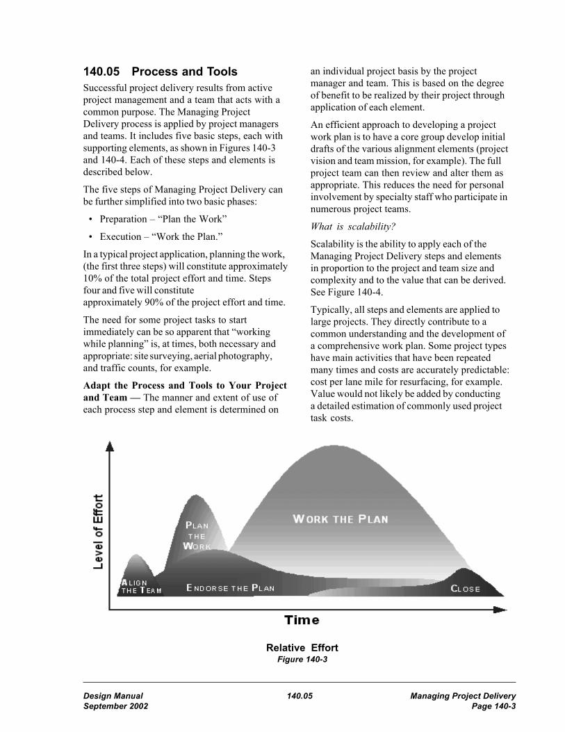
140.05 Process and ToolsSuccessful project delivery results from activeproject management and a team that acts with acommon purpose. The Managing ProjectDelivery process is applied by project managersand teams. It includes five basic steps, each withsupporting elements, as shown in Figures 140-3and 140-4. Each of these steps and elements isdescribed below.
The five steps of Managing Project Delivery canbe further simplified into two basic phases:
• Preparation – “Plan the Work”
• Execution – “Work the Plan.”
In a typical project application, planning the work,(the first three steps) will constitute approximately10% of the total project effort and time. Stepsfour and five will constituteapproximately 90% of the project effort and time.
The need for some project tasks to startimmediately can be so apparent that “workingwhile planning” is, at times, both necessary andappropriate: site surveying, aerial photography,and traffic counts, for example.
Adapt the Process and Tools to Your Projectand Team — The manner and extent of use ofeach process step and element is determined on
Relative EffortFigure 140-3
an individual project basis by the projectmanager and team. This is based on the degreeof benefit to be realized by their project throughapplication of each element.
An efficient approach to developing a projectwork plan is to have a core group develop initialdrafts of the various alignment elements (projectvision and team mission, for example). The fullproject team can then review and alter them asappropriate. This reduces the need for personalinvolvement by specialty staff who participate innumerous project teams.
What is scalability?
Scalability is the ability to apply each of theManaging Project Delivery steps and elementsin proportion to the project and team size andcomplexity and to the value that can be derived.See Figure 140-4.
Typically, all steps and elements are applied tolarge projects. They directly contribute to acommon understanding and the development ofa comprehensive work plan. Some project typeshave main activities that have been repeatedmany times and costs are accurately predictable:cost per lane mile for resurfacing, for example.Value would not likely be added by conductinga detailed estimation of commonly used projecttask costs.
Design Manual 140.05 Managing Project DeliverySeptember 2002 Page 140-3

1 Initiate
and align
the team
2
Plan
the Work
3
Endorse
the Plan
4
Work
the Plan
5
Close
the Project
Operating
Guidelines
Risk
AssessmentSponsor Communicate Archive
Project
Vision
What - Work
Breakdown StructureCustomer
Customer
Relationships
Reaching Closure
with Customers
Team
Mission
Task
Planning
Project
Team
Team
BuildingDemobilize
Communications
Plan
Roles and
Responsibilities
Costs and
Budget
Manage
Change
Reward and
Recognize
BoundariesWhen -
Schedule
Managing Scope,
Schedule & Budget
Learn and
Improve
Change
Management Plan
Steps
Ele
me
nts
ExecutionPreparation
Measures
of Success
(1) Initiate and Align the Team• Initiate the project.
• Build the project team.
• Align the participants toward a common goal.
While the assignment of organizations andindividuals to a project is an essential first step,mere assignment does not result in an effectiveteam. Teams must be built and sustained. (See140.04(4)(b), Team Building.) For successfulproject delivery, the participants must conducttheir efforts in a coordinated and complimentarymanner. Establishing communication among thepeople who will develop and deliver the project isthe most important function of this first stepof Managing Project Delivery. Successful projectdelivery starts with mobilizing the necessaryresources and aligning the participants towarda common goal.
Building and sustaining an effective project teaminvolves initiating the project by developing acommon understanding of:
• Project vision
• Team mission
• Participant roles and responsibilities
• Project boundaries
• Critical success factors
What is a project team?
The project team is a designated group of peopleworking together with a common purpose relatedto a specific project. A critical aspect of projectsuccess is mobilizing and aligning people around aproject to effectively deliver the product.
Managing Project DeliverySteps and Elements
Figure 140-4
Managing Project Delivery 140.05(1) Design ManualPage 140-4 September 2002

Who should be on the team?
The project manager assesses what skills arerequired for the specific project and securespeople with those skills to accomplish the projecteffort. Many projects require multidisciplinaryparticipation. The project manager must secureindividuals from the appropriate functionalspecialty groups (potentially including Bridge,Environmental, Geotechnical, Local Programs,Materials, Real Estate Services, Traffic, Utilities,and others). This is necessary to overcome theestablished tendency of large organizations tosegregate or compartmentalize.Compartmentalization commonly resultsin disjointed and conflicting deliverables.
Depending on the scope of the project,participation on the team by “partners” isappropriate and can serve to ensure that theproduct meets customer expectations.Identification of appropriate representatives isnecessary for each project and, to be meaningful,needs to be individuals who can communicatedirectly with the project team. Examples are:
• Elected officials at the federal, state, andlocal level
• Representatives of Indian tribes
• Staff from appropriate agencies orjurisdictions
• Staff from permitting agencies
• Stakeholders
• Neighborhood residents
• Individuals who regularly use the facility
To be both effective and efficient, theparticipants’ efforts need to complement oneanother in support of accomplishing a commonpurpose, in other words, to function as acollaborative team. This does not mean that allteam members must participate in every teammeeting or project work session. Active projectmanagement includes ongoing determination ofnecessary participants to be effective andefficient.
Some project managers have found that adesignated project Leadership/Management Teamis an effective supplement to a Production Team.
This approach is particularly useful for very largeprojects. Communicating with and seekingendorsement from customers is an essentialaspect of successfully managing project delivery.Some project managers have determined thatforming these participants into a Steering Teamor Citizen Advisory Committee is the mosteffective format.
(a) Project Vision
What will be the result of this project?
The project vision establishes the common goaltoward which all project activities and effortsstrive. It is a statement of the desired HighwayConstruction Program project product (facilityor service). The project vision describes anoutcome (the final product, not a process) and isintended to incorporate customer and stakeholderneeds and expectations as well as team input.
(b) Team Mission
How will the team accomplish the project?
The Team Mission statement serves to establishthe common understanding of what a specificteam is to accomplish. It is a statement of theoverall actions the team will take to accomplishthe project. It is usually a short paragraphdeveloped with input from the team, includingparticipating stakeholders and customers, as wellas from the project sponsor.
In this chapter, “the project” means theTeam Mission — The word project is usedthroughout this chapter. It is imperative to under-stand and communicate the distinction betweenthe defined Team Mission (“the project” forpurposes of this chapter) and a “HighwayConstruction Program project.” A HighwayConstruction Program project is developed inphases (scoping, design, PS&E, right of way,and construction.) A specific Team Mission maybe constrained to a specific phase or phases ofa Highway Construction Program project. It isentirely likely that the Team Mission of any givenproject team will not attain the ultimateend product of the Highway ConstructionProgram project, “the project vision.”
Design Manual 140.05(1)(b) Managing Project DeliverySeptember 2002 Page 140-5

The Team Mission statement is of particularimportance during project work planning as itdetermines the scope of the Work BreakdownStructure, (starting with project specific tailoringof the Master Deliverables List [140.04(2)(a)],which is the basis of the schedule and estimatedcost to complete.
(c) Operating Guidelines
How will the team govern itself?
The operating guidelines describe how the teamwill govern itself both within and outside of teammeetings. The functions most commonlyperformed by the team and guidelines to steer it inthose functions are identified. Listed below aresome guidelines the team might wish to develop:
• Team decision process.
• Team meetings (such as structure, timing).
• Communication (such as methods, uses,frequency, protocols).
• Measuring team performance (such as teamsurveys, self-assessments/evaluations).
• Managing team disagreement and conflict.
• Managing team change (such as changes inteam membership).
(d) Boundaries
What do boundaries define?
Boundaries define the limits relevant to the projectand the team’s mission. Boundaries are usuallyset by the organization and transmitted to theteam by the project sponsor. Someboundaries are established by other entitiesbeyond the team. Boundaries might fall within thefollowing areas:
• Geographic.
• Financial.
• Legal and regulatory.
• Mandatory product delivery dates.
• Required project activities.
• Excluded project activities.
What benefit is derived from identifyingboundaries?
The identification of project boundaries provides avaluable opportunity for the team, the sponsor,and appropriate customers to enhance theircommon understanding of the projectenvironment. Well defined project boundaries canbe very useful for identifying potential change.Teams frequently find it valuable to distinguishgoals (desirable but not mandatory elements) fromabsolute boundaries.
(e) Roles and Responsibilities
What are roles and responsibilities?
Roles and responsibilities can be defined for eachorganization participating in the project or down tothe level of each individual on the project team.The definition and mutualacceptance of organizational and individual rolesand responsibilities expedites arrival at acommon understanding of “who will do what.”
The team member’s roles are the specific titlesor positions occupied, such as team leader,designer, permit coordinator, drafter, etc. Theresponsibility is the output or outcome expectedof the team or individual, such as plan sheets,hydraulic analysis, schedules, etc.
A project-specific table of organization chart isa good tool for visualizing needed and assignedhuman resources, their roles and responsibilities,and the relationships or linkages between theparticipants.
(f) Measures of Success
How will accomplishment of the team’s missionbe measured?
Measures of success are tools to assess theaccomplishment of critical success factors.Critical success factors define the most importantthings the team must accomplish to fulfill itsmission and achieve project success. Thesefactors are tied to the team mission and projectvision.
The first step is to define critical success factors.Once these factors are defined, ways to measuretheir attainment are developed. Attainment of thecritical success factors is measured incrementally
Managing Project Delivery 140.05(1)(b) Design ManualPage 140-6 September 2002

“along the way,” not just at the point of projectcompletion. This allows for corrective action(changes) to get “back on track.”
(2) Plan the WorkWhat is the goal of planning the project work?
The goal is a work plan that is comprehensive,realistic, deliverable, and endorsed by all teammembers.
Planning the work to accomplish the TeamMission — It is imperative to understand andcommunicate the distinction between the workplan (including schedule and cost to complete)to accomplish the defined Team Mission and theentire effort to deliver the Highway ConstructionProgram project in terms of preliminaryengineering (PE), right of way (ROW), andconstruction (CN) phases.
The following are examples:
• For a Team Mission to conduct the scopingphase of a Highway Construction Programproject, work planning elements for thedesign, PS&E, ROW, and CN phases(including schedule and cost to complete)will be deliverables accomplished as part offulfilling the Scoping Team’s Mission. Theselater phase schedules and cost estimates willbe output from “working the plan” to scopethe project. The “plan the work” scheduleand budget in this example are only foraccomplishing the Team Mission to scopethe project.
The scope of work, schedule to deliver, andthe estimated cost to complete a HighwayConstruction Program project (including PE,ROW, and CN phases) are developed by aregion project team during the scoping phase,and become commitments upon signature ofthe Project Definition and entry into theCapital Improvement & PreservationProgram (CIPP).
Once a Highway Construction Programproject’s scope, schedule, and estimated cost(PE, ROW, CN) have been committed to inthe CIPP, if at any point in the furtherdevelopment of that project the delivery dateor estimated cost exceed the commitments in
the CIPP, the Change Management Plan willbe implemented by the Project Manager. (See140.05(2)(g), Change Management Plan.)
• When the Team Mission is to conduct thedesign or PS&E subphases of a project, the“plan the work” schedule and cost estimateare a test or verification of the project PEschedule and cost estimate commitment inthe CIPP. In the case of a Team Mission toconduct the design or PS&E of a project,a construction phase schedule and costestimate will be “working the plan”deliverables.
(a) What — Work Breakdown Structure
What needs to be done to accomplish the teammission and deliver this project?
The Work Breakdown Structure (WBS) isa systematic mapping out of the hierarchicalproject tasks (necessary to accomplish the TeamMission) to the lowest level of detail necessaryto describe and assign the tasks. The WBS toolis useful toward developing a project scope,schedule, and budget. The team develops theWBS with input from project customers andstakeholders. The WBS includes all tasksnecessary to accomplish the team mission.
A task is an assignable item of work that has:
• A definable beginning and end.
• A finite duration.
• An associated level of effort (such as labor,money, equipment, and materials).
• A state of completion that can be estimatedat any time.
• A reviewable internal or external deliverableat the task’s completion.
Master Deliverables List – Implementation ofthe PDIS, using project scheduling software,includes establishment of an agency widestandard Master Deliverables List (MDL). TheMDL is a work breakdown, down to thedeliverable level, and is to be used by all projectsin the Highway Construction Program. It servesas the starting point for development of eachproject-specific Work Breakdown Structure. Withonly a few exceptions, the MDL does not include
Design Manual 140.05(2)(a) Managing Project DeliverySeptember 2002 Page 140-7

tasks. Tasks must be defined for each project. Thetasks developed at the project level must roll upinto the deliverables in the standardized MDL,which is available on the WSDOT Internet site.See the PDIS definition for a web address.
(b) Task Planning
How is the project work plan developed from thetasks (WBS) to a comprehensive and realisticschedule and then a budget?
Task planning serves as an essential intermediatestep between the WBS and schedule layout.Developing the schedule directly from the WBShas an extremely high risk of resulting in aninaccurate schedule due to incompletely definedtasks. Figures 140-7a and 140-7b are a TaskPlanning Worksheet available for use inaccomplishing this step. This worksheet is alsoavailable at www.wsdot.wa.gov/eesc/design/policy/designpolicy.htm
Task planning includes the following:
• Task scope definition. Just as the overallproject requires a well developed andcommunicated scope, so do the supportingtasks. For example, for “Public InformationNewsletters” task, will there be 1, 3, or 5mailings, to 500, 5000, or 10,000 addresses,and will they be 1, 3, or 5 pages in length?How will they be distributed?
• Task sequencing. The accurate sequencingof tasks is critical to the later effectivedevelopment of a realistic and deliverableschedule. The recurring question asked inthis process is “To execute this task, whatdo I need from some other task, and whendo I need it?” Identifying task dependenciesbetween functional areas is of criticalimportance (Design and Bridge,Environmental and Design, Hydraulicsand Right of Way, etc.)
• Resource assignments. What organizationand what specific individuals will conduct thistask? Will 1 or 3 drafters be assigned to thistask? Are the specific individuals highlyexperienced or “first timers”? Whatavailability constraints apply to theindividuals assigned to this task: other
project assignments, percentage of timecommitted to this project, training needs,vacations, and the like?
Accomplishing this work planning elementis a key to ultimately attaining a resourceloaded schedule. The software entry ofresources is dependent on this task planningfunction.
• Task duration estimates. Those individualswith the applicable expertise can make themost accurate estimates for completion oftasks. Expert judgment guided by historicalinformation is used whenever possible.Project managers must seek input fromthose who will accomplish specific tasksto estimate the realistic duration.
(c) Risk Assessment
What risks does this project face and how canthey best be managed to ensure successfuldelivery?
Project risks can be opportunities (positiveevents) as well as threats (negative events) thatmight affect scope, schedule, or budget. Riskassessment is the first phase of project riskmanagement, the purpose of which is tomaximize the results of positive events andminimize the consequences of adverse events.See A Guide to the Project Management Bodyof Knowledge for more details. Risk assessmentincludes the following:
1. Risk Identification is determining whichrisks are likely to affect the project and thecharacteristics of each. This includes bothinternal (things the project team can control)and external (beyond the control or influenceof the team) risks. Identify risks fromhistorical information, interviewing ofstakeholders, subject matter experts, andteam brainstorming.
2. Risk Quantification is identifying therisks for which a contingency plan willbe developed.
An effective tool for quantifying projectrisks is the Risk Probability – Impact Matrixshown in Figure 140-5. Each identified riskis assessed for probability of occurrence anddegree of impact to the project, should it
Managing Project Delivery 140.05(2)(a) Design ManualPage 140-8 September 2002

occur. Assessment of risks is a judgmentcall based on the best available insight. Risksidentified as both high probability and highimpact (red risk) are potential “showstoppers” and must be further addressedimmediately. All risks determined to bemedium to high in both probability andimpact (yellow risk) are given continuousmanagement and, probably, developmentof contingency plans.
3. Risk Response Development. Responses torisk threats include the following:
• Avoidance — eliminating the threat,usually by eliminating the cause.
• Mitigation — reducing the potentialprobability of occurrence.
• Acceptance — accepting theconsequences either actively (with acontingency plan) or passively.
The reason for conducting risk assessment beforeschedule and budget building is to provide theopportunity to develop and incorporate scheduleand budget contingencies for “at risk” tasks.
High Gray Yellow RedArea Risk Risk
Med. Yellow YellowRisk Risk
Low GrayArea
Low Med. High
Probability
Risk Probability – Impact MatrixFigure 140-5
(d) When — Schedule
When will the project tasks be conducted?
All projects in the WSDOT HighwayConstruction Program are managed using aschedule of required activities that is based onthe standardized Master Deliverables List.
The schedule to complete the Team Mission isdeveloped from the Work Breakdown Structureand the subsequent task planning. The scheduleis a dynamic tool. It defines the start, order, andduration of project tasks and milestones. Acollaboratively developed and comprehensiveschedule is a fundamental tool for the subsequentmanagement and delivery of the project. It is usedto communicate, coordinate, and measure projectprogress.
Identifying and managing task dependenciesbetween functional areas (Design toEnvironmental, Geotechnical to Bridge, Trafficto Design, etc.) are of major importance tosuccessful project delivery. Milestones andinterim deliverables make schedule, and thusproject management, much easier and moreeffective by providing both short-term goalsand clear measurements of progress.
When schedules are resource loaded it becomespossible to balance the assignment of resourcesand identify over-allocated resources using theschedule. Resource balancing can beaccomplished within an individual project andacross multiple projects when all involvedschedules are resource loaded. The developmentof a schedule-based budget is also feasible oncea schedule is fully resource loaded.
(e) Costs and Budget
How much will it cost to accomplish the TeamMission in accordance with the projectschedule?
The estimated cost to complete the Team Missionis developed from the Work BreakdownStructure, assigned project resources, and theresultant comprehensive schedule. This estimateis broken down by participating functional area(Bridge, Environmental, Real Estate, etc.), aswell as by month (“aged”). It includes anappropriate contingency allowance for identifiedrisk areas and inaccuracies in the cost estimatingprocess.
The estimated cost to accomplish the TeamMission includes all activities that will be directlyor indirectly charged against the project such as“planning the work,” quality assurance andcontrol, project management, and project closure.
Impa
ct
Design Manual 140.05(2)(e) Managing Project DeliverySeptember 2002 Page 140-9

(f) Communication Plan
Communication, the exchange of informationto the relevant parties (including ideas,expectations, goals, requirements, and status),is vital to project success. To be effective,communication cannot be left to chance. Whilethe theme of communication permeates the entireManaging Project Delivery process, a specificcommunication plan is an essential tool forsuccessful project delivery. See Chapter 210,“Public Involvement and Hearings.”
Communication has many dimensions:
• Internal (within the project)
1. Vertical (up & down the organization)
2. Horizontal (with peers)
• External (to stakeholders, the media, thecustomers)
• Written, oral, and various media
1. Letters, memos, e-mail
2. Internet
3. Media (radio, TV, newspapers)
4. Personal contacts
5. Public meetings and hearings
Every project develops or adopts acommunication plan. Communication planelements include the following:
• Requirements — Determining theinformation and communication needs ofthe project stakeholders and participants:who needs what information, when willthey need it, and how will they get it.
• Distribution Structure – Defining thefollowing:
1. To whom information will flow (statusreports, data, schedule, etc.).
2. What methods will be used todistribute various types of information(written reports, letters, meetings, e-mail,Internet).
3. When each type of communication willbe produced.
4. Who, in the project organizationalstructure, is responsible for preparingand distributing the identified items.
(g) Change Management Plan
Successful project delivery requires activeidentification and analysis of encounteredchange, leading to effective decisions. Acommon human tendency is to deny that changeis occurring until it becomes overwhelming. AChange Management Plan (CMP) provides theframework for decision making when changeoccurs. Since it is not possible to foresee allpotential changes, a project manager plans themethods by which change will be addressedwhen encountered.
The CMP includes the following elements:
• A means to anticipate and identify potentialchanges.
• A process for assessing the effects of achange.
• Techniques and procedures for developinga response strategy.
• A change endorsement process, includingidentification of the level of endorsementnecessary for various types of change.Endorsement is by definition proactive suchthat endorsement of any change is necessarybefore resources are expended to implementthe change.
• A process for revising the work plan andmonitoring performance in accordance withthe revised work plan.
• A communication strategy to inform allaffected parties of the project changes.
WSDOT has adopted standardized changemanagement procedures for the CapitalImprovement and Preservation Program (CIPP).These procedures, including a standardizedChange Management Form, are used by bothProject Development and Program Management.Detailed information on this CIPP changemanagement process, including the ChangeManagement Form, are available on the web.See Figure 140-6, and the definition for CIPP forthe web address.
Managing Project Delivery 140.05(2)(f) Design ManualPage 140-10 September 2002

(3) Endorse the PlanWhat is endorsement, how is it different fromapproval, and who are the key parties toendorse the plan?
Endorsement constitutes both buy-in andcommitment to the work plan and projecteffort by the key participants. Endorsement isproactive, whereas approval is typically reactive,frequently meaning no more than a lack ofobjection. Endorsement is the key participantstaking ownership of the project goals and theagreed upon method by which the goals will bedelivered.
The optimal method to gain endorsementof the project work plan is by inclusion of theparticipants in the collaborative developmentof the work plan. This will provide ownershipof the plan by the participants and help to reachendorsement by consensus.
The project manager determines whetherendorsement for the project work plan willbe achieved verbally or documented.
(a) Customers
A primary purpose of endorsement is to gaincustomer commitment to support the project teamand work plan. Endorsement by the customers isintended to ensure their understanding of theproject and acceptance of the project scope,schedule, and budget.
(b) Project Team
The purpose for endorsement by the project teamis to:
• Share a mutual understanding of the workplan.
• Actively concur that the plan iscomprehensive, realistic, and deliverable.
• Demonstrate that the team is committed tocompleting the project as described in theplan.
This endorsement validates the workingrelationship between members of the team andbetween the team and the project manager.
(c) Sponsor
Endorsement of the project work plan by theproject sponsor, and other managers designatedby the project sponsor, provides:
• Sponsor commitment to the defined scope,schedule, and budget.
• Necessary staff (skill base, knowledge,experience).
• Required tools and resources (computers,technology, office space).
• Sponsor acknowledgement of known risksand associated contingencies.
• Sponsor commitment to advising andassisting in executing the project.
• Sponsor commitment to applyingmanagement’s authority toward successfulaccomplishment of the work plan and project.
In order to facilitate sponsor/managementendorsement, it is advisable to involvemanagement in the project work plandevelopment to some degree. The level ofinvolvement will vary by project.
(4) Work the Plan(a) Customer Relationships
• Know the customer’s expectations.
• Involve the customers as they wish to beinvolved.
• Communicate progress to customers as theydesire.
• Resolve conflict as necessary.
• Manage customer expectations.
(b) Team Building
A team must be both built and sustained.Teams are dynamic. Their movement acrossthe spectrum of team development (forming,storming, norming, performing, excelling) isongoing and must be continually managed toattain high performance, produce results, anddeliver the project.
Design Manual 140.05(4)(b) Managing Project DeliverySeptember 2002 Page 140-11

• A team is a group of individuals who workfor a common purpose to produce a specificoutcome.
• A team continuously develops group andindividual skills to enhance teamperformance on the project.
• An effective team develops and implementsa reward and recognition strategy.
• A team works together to correctmistakes in ways that minimize negativeimpacts on the project.
• A team works together to learn frommistakes.
(c) Communicate
Effectively exchanging the necessary informationbetween project participants and interested partiesis essential for project delivery. Project managersand teams apply the Communications Planadopted for the project.
(d) Managing Scope, Schedule, and Budget
Successful project delivery (on time, withinbudget, and meeting requirements – includingmeeting or exceeding customer expectations)requires active management of scope, schedule,and budget including the following:
• An endorsed base line scope,schedule, and budget.
• Ongoing communication with all teammembers to get frequent and accurate dataon progress.
• Regular schedule and budget monitoring andevaluation with revisions to reflect actualprogress, as appropriate.
• Regularly reporting progress to customersand stakeholders.
All projects in the WSDOT HighwayConstruction Program will maintain currentschedules in the PDIS. Project schedules willbe updated frequently enough to ensure theproject delivery date shown in PDIS isaccurate and can be met.
The scope, schedule, and budget tradeoff trianglefunctions as a link and pin truss where the sidesmust remain connected. See Figure 140-2. When
one side changes, the influences or impactsof that change on the other two sides must bemanaged. A cardinal rule in project managementis that, whenever scope, schedule, or assignedproject resources change, a corresponding budgetchange is mandatory. The application of this ruleoften requires involvement and assistance fromothers who will be expected to endorse theresulting updated plan.
(e) Manage Change
Recognizing and confronting change rather thanavoiding it is key to successful project delivery.Value can be added through appropriate changemanagement. Changes can save money and time.Active change management, through use of anestablished Change Management Plan, canminimize adverse effects on project delivery.
Proactive endorsement (by the necessaryauthority) of changes to project scope, schedule,or budget must be obtained before resources areexpended to implement the change. See140.05(2)(g), Change Management Plan; Figure140-6; and the associated web page for additionalinformation on the change management processfor projects in the CIPP. See the definition forCIPP for the web address.
Frequent and meaningful communicationbetween project participants (including teammembers, sponsor, and customers/stakeholders)is an essential element of actively managingchange. It is the responsibility of the teammembers familiar with the scope, schedule,and budget to continuously identify potentialchanges in those areas.
(5) Close the ProjectTo conduct an effective closure, or phasetransition, it is important for the project managerand team to define what closure means for thisteam and project. The following are commonclosure situations:
• Final closure. The final project vision hasbeen attained. If so, this is probably anultimate closure for the overall project effort.
• Transition. One team has accomplished itsmission, but a transition or handoff must bemade to a subsequent team tasked with
Managing Project Delivery 140.05(4)(b) Design ManualPage 140-12 September 2002

furthering the overall effort toward attainmentof the project vision. This is typical betweenmajor project development phases suchas between design and construction.A thoroughly conducted transition is criticalfor being ultimately successful in deliveringthe product for the customers.
• Shelf. A project effort that has reached atemporary closure point and is being put“on the shelf” is a transitional event to afuture team that probably has not even beenassigned. Comprehensive documentation ofthe project status, backup, and decisions (withjustifications) is especially critical in thissituation to minimize rework when the effortis restarted.
(a) Reaching Closure With Customers
This is the process of following up with thecustomers of the project and all affected parties.This includes the review of successes and failuresin the eyes of the customers in relation to theproject. This is planned for throughout the projectand might occur at multiple intermediate stages ofthe project.
(b) Demobilize
This is a planned strategy for the reassignmentor redistribution of project staff and resources.A demobilization/remobilization strategy is tiedto the project schedule and evaluated and updatedaccordingly.
(c) Archive
The team addresses archiving as follows:
• Plan archiving at the beginning of the project.
• Plan the documentation for the permanentdesign file as required by other DesignManual chapters and consider alsodocumenting selected MPD documents.
• Include archiving in the project schedule.
• Budget for archiving effort.
• Tailor archiving effort to project size andcomplexity to comply with legal requirements(including preparedness for Freedom ofInformation Act requests) and to providean administrative record of the project.
• Archive throughout the project.
• Adhere to agency-wide archiving processand standards. Communicate guidelinesto team through the closure plan.
(d) Learn and Improve
The purpose of this element is to build corporateknowledge and skills and minimize the need forthose in the future to “reinvent the wheel.” Thisevaluation element is valuable for sharing withothers (including other WSDOT staff andpotential future team members) what waslearned on this project: “What went well,what didn’t, and why.” The areas of evaluationusually include:
• Staff evaluation and development.
• Comparison of initial objectives with results.
• Review of significant changes, reasons, andresults.
• Effectiveness of the work plan.
• Budget assessment.
• Customer satisfaction.
• Comparison to measures of success asestablished in the work planning process.
(e) Reward and Recognize
Rewarding and recognizing team members andcustomers, as well as celebrating overall teamsuccess, are important steps and contributetoward the success of future project teamendeavors.
140.06 Responsibilities
(1) Project SponsorThe project sponsor provides the direction,authority, and resources for implementingManaging Project Delivery on projects. Typically,the project sponsor is a department executive,office manager, or organizational unit managerwho assigns the project manager.
(2) Project ManagerThe project manager follows the ManagingProject Delivery process and applies specializedknowledge, skills, tools, and techniques to carry
Design Manual 140.06(2) Managing Project DeliverySeptember 2002 Page 140-13

out the project sponsor’s direction through projectcompletion. A project manager has the followingresponsibilities:
(a) To the project sponsor
• Come to a mutual understanding of theproject work plan (including scope, schedule,budget, and other primary elements of theproject) to obtain the endorsement of theproject sponsor.
• Communicate project progress usingappropriate project status reports andmeetings.
• Identify when project sponsor endorsementwill be required throughout the project.
• During the project, communicate anysignificant changes in scope, schedule,budget, or customer satisfaction.
• Deliver the project in accordance with theendorsed work plan, including schedule andbudget.
(b) To the project customers
• Understand customer needs and expectations(listen).
• Communicate progress to customers (keepthem informed).
• Communicate change and provide optionsto gain endorsement of preferred choices.
• Deliver the project in accordance with theendorsed project work plan.
• Solicit and incorporate customer feedbackin project closure.
(c) To the project team members
• Provide leadership and management.
• Be an advocate for the team.
• Obtain team endorsement on the project workplan, and major changes.
• Facilitate internal and externalcommunication.
• Manage change in scope, schedule,and budget.
• Initiate ongoing team building.
• Mentor team members in projectmanagement.
(d) To other project managers
• Mentor each other by sharing experiencesand knowledge.
• Encourage each other to achieve projectmanagement excellence.
• Share resources when appropriate.
• Coordinate project work plans.
(3) Project Manager and TeamThe project manager and team apply the fivesteps of the Managing Project Delivery process tothe project. See Figure 140-4.
140.07 DocumentationIs documentation of a project work planrequired?
Preparation of a project work plan document isnot mandatory. However, documentation of theseelements is an effective means of attaining acommon understanding among team members,the project sponsor, and customers. Suchdocumentation can be in the form of a teamcharter or agreement or it can be a project workplan, including the team alignment elements.An additional benefit of such documentation isfor ready communication to new team membersand outside parties concerning what the teamorganization and work plan are for this specificproject.
See 140.05(5)(c), Archive, regardingdocumenting to the permanent DesignDocumentation File.
Managing Project Delivery 140.06(2) Design ManualPage 140-14 September 2002

Date Submitted: _________ Change Management FormFor: Unprogrammed Project
Scope Change Cost Change Schedule Change
1. Project Title:SR, Title, MP to MP
Location: Transportation Region:Program Item No.: Legislative District:Work Item No: Subprogram:Project Summary Approved (or status):Project Summary Cost Estimate: Confidence Factor:
2. Project Description:
3. Summary of Change Proposal:Description of Change (Reason, What, Why, How):Proposed program adjustments to accommodate unprogrammed project or cost/scope/schedule change:
5. Project Status Summary ($ in 1000s):CN Start Date PE RW CN 01-03 Exp. Total Cost
CIPPLast ApprovedProposedTotal Change
New Confidence Factor: +/- %
6. Approval Concurrence & Authority (See attached thresholds):Initials Date
Project Engineer ____ ________Region Project Development Engineer ____ ________Region Program Manager / Region Administrator ____ ________HQ ASDE ____ ________Other: __________________________ ____ ________HQ Program Manager ____ ________HQ Program Delivery Manager ____ ________Director, Planning & Capital Program Management ____ ________Department Project Screening Board ____ ________
7. Comments:
8. Approving Authority’s Response:ApprovedApproved with conditions (see comments)Needs additional evaluation or information (see comments)
9. Approving Authority’s Comments:10. Approving Authority’s Signature(s)Approval Date: ________________================================(For publication:)==================================
11. Program delivery issues that address the cause of the unprogrammed project or cost/scope change – the focus is toidentify lessons learned
12. Action plan outlining corrective actions implemented/proposed to address the identified program delivery issues– the focus is to preclude recurrence of the same issues
Notification of Submitter on (Date): _______________
Design Manual Managing Project DeliverySeptember 2002 Page 140-15
Change Management FormFigure 140-6

Predecessor Tasks – Identify as Finish-Start (FS), Start-Start (SS), Finish-Finish (FF)
Task Dependencies and Sequencing:
Task Description – “Scope of Work”
Successor Task– Identify as Finish - Start (FS), Start-Start (SS), Finish-Finish (FF)
Concurrent (parallel) Tasks
Task Planning WorksheetFigure 140-7a
WBS Code Task Name Task #(use MDL) (Optional)
Managing Project Delivery Design ManualPage 140-16 September 2002

Resource Considerations:
Resource Assignments (organization, individuals, equipment)
Resource Constraints (availability, experience level, training needed, etc.)
Estimates for Task Duration, Hours, & Cost:
Pessimistic Most Likely Optimistic
Calendar Time to Complete Task (start to finish)
Staff Hours to Complete Task
Cost to Complete Task
PERT (Program Evaluation and Review Technique) Task Duration Estimate
OD = Optimistic Duration MWF = Most Likely Weighting Factor = 4
OWF = Optimistic Weighting Factor = 1 PD = Pessimistic Duration
MD = Most Likely Duration PWF = Pessimistic Weighting Factor = 1
Task Planning WorksheetFigure 140-7b
WFWFWF
WFDWFDWF
PMOPPMMO
++×+×+×
=)()()(O Duration Expected D
Design Manual Managing Project DeliverySeptember 2002 Page 140-17


325 Design Matrix Procedures
325.01 General325.02 Terminology325.03 Design Matrix Procedures325.04 Selecting a Design Matrix325.05 Project Type325.06 Using a Design Matrix
325.01 GeneralThis highway Design Manual provides guidancefor three levels of design for highway projects:the basic, modified, and full design levels. Thedesign matrices in this chapter are used to iden-tify the design level(s) for a project and theassociated processes and approval authority forallowing design variances. The matrices addressthe majority of preservation and improvementprojects and focus on those design elements thatare of greatest concern in project development.
The design matrices are five tables that areidentified by route type. Two of the matricesapply to Interstate highways. The other threematrices apply to preservation and improvementprojects on non-Interstate highways.
325.02 TerminologyThe National Highway System (NHS) consistsof highways designated as a part of the InterstateSystem, other urban and rural principal arterials,and highways that provide motor vehicle accessto facilities such as a major port, airport, publictransportation facility, or other intermodaltransportation facility. The NHS includes ahighway network that is important to the UnitedStates strategic defense policy and providesdefense access, continuity, and emergencycapabilities for the movement of personnel,materials, and equipment during times of war andpeace. It also includes major network connectorsthat provide motor vehicle access between majormilitary installations and other highways that arepart of the strategic highway network.
The Preventive Maintenance mentioned underproject type on Interstate Design Matrices 1 and 2includes roadway work such as pavementpatching; restoration of drainage system; panel
replacement; joint and shoulder repair; and bridgework such as crack sealing, joint repair, seismicretrofit, scour countermeasures and painting.Preventive maintenance projects must notdegrade any existing safety or geometric aspectsof the facility.
In Design Matrices 1 and 2 and in Figure 330-1,the term New/Reconstruction includes thefollowing types of work:
• Capacity changes: add a through lane, convert ageneral purpose (GP) lane to a special purposelane (such as an HOV lane), or convert a highoccupancy vehicle (HOV) lane to GP.
• Other lane changes: add or eliminate acollector-distributor or auxiliary lane. (Arural truck climbing lane that, for its entirelength, meets the warrants in Chapter 1010is not considered new/reconstruction.)
• Pavement reconstruction: full depth PCC orAC pavement replacement.
• New interchange
• Changes in interchange type such as diamondto directional
• New or replacement bridge (main line)
The HAL, HAC, PAL, and Risk locationmentioned in the notes on Design Matrices 3, 4,and 5 are high accident locations (HAL), highaccident corridors (HAC), pedestrian accidentlocations (PAL), and locations that have a highprobability of run-off-the-road accidents basedon existing geometrics (Risk).
The Non-Interstate Freeway mentioned onDesign Matrices 3, 4, and 5 is a multilane,divided highway with full access control.
The Master Plan for Access Control mentionedin the notes on Design Matrices 3, 4, and 5 isavailable from the Headquarters, Design Office,Access and Hearings Unit.
The corridor or project analysis mentioned innotes 2 and 4 (on Design Matrices 3, 4, and 5)is the justification needed to support a change
Design Manual Design Matrix ProceduresSeptember 2002 Page 325-1

in design level from the indicated level. Theanalysis can be based on route continuity, andother existing features, as well as the recommen-dations for future improvements in an approvedRoute Development Plan. See Chapter 330 for asample project analysis.
(1) Project TypesDiamond Grinding is grinding a concretepavement to remove surface wear or jointfaulting.
Milling with AC Inlays is removal of a specifiedthickness of asphalt surfacing, typically from thetraveled lanes, and then overlaying with asphaltconcrete at the same specified thickness.
Nonstructural Overlay is an asphalt concretepavement overlay that is placed to minimize theaging effects and minor surface irregularities ofthe existing asphalt concrete pavement structure.The existing pavement structure is not showingextensive signs of fatigue (longitudinal or alliga-tor cracking in the wheel paths). Nonstructuraloverlays are typically less than 0.13 ft thick.
AC Structural Overlay is an asphalt concretepavement overlay that is placed to increase theload carrying ability of the pavement structure.Structural overlay thickness is greater than orequal to 0.13 ft.
PCC Overlay is a Portland cement concretepavement overlay of an existing PCC orAC pavement.
Dowel Bar Retrofit is re-establishing the loadtransfer efficiencies of the existing concretejoints and transverse cracks by the cutting ofslots, placement of epoxy coated dowel bars,and placement of high-early strength,non-shrink concrete.
Bridge Deck Rehabilitation is repair of anydelaminated concrete bridge deck and addinga protective overlay that will prevent furthercorrosion of the reinforcing steel.
Safety, All Others includes collision reduction,collision prevention, channelization, andsignalization projects.
Safety, At Grade is a project on a multilanehighway to build grade separation facilities thatreplace the existing intersection.
Bridge Restriction projects are listed undereconomic development because these bridges donot have any structural problems. However, if thevertical or load capacity restrictions are removed,then it will benefit the movement of commerce.
(2) Design ElementsThe following elements are shown on the DesignMatrices. If the full design level applies, seethe chapters listed below. If basic design levelapplies, see Chapter 410. If the modified designlevel applies, see Chapter 430.
Horizontal Alignment is the horizontal attributesof the roadway including horizontal curvature,superelevation, and stopping sight distance; allbased on design speed. (See Chapter 620 forhorizontal alignment, Chapter 640 forsuperelevation, Chapter 650 for stopping sightdistance, and Chapter 440 for design speed.)
Vertical Alignment is the vertical attributes ofthe roadway including vertical curvature, profilegrades, and stopping sight distance; all based ondesign speed. (See Chapter 630 for verticalalignment, Chapters 440 and 630 for grades,Chapter 650 for stopping sight distance, andChapter 440 for design speed.)
Lane Width is the distance between lane lines.(See Chapter 640.)
Shoulder Width is the distance between theoutside or inside edge line and the edge ofin-slope, or face of barrier. (See Chapter 640.)
Lane Transition (pavement transitions) are therate and length of transition of changes in widthof roadway surface. (See Chapters 440 and 620.)
Median Width is the distance between insideedge lines. (See Chapters 440 and 640.)
Cross Slope, Lane is the rate of elevation changeacross a lane. This element includes the algebraicdifference in cross slope between adjacent lanes.(See Chapter 640.)
Cross Slope, Shoulder is the rate of elevationchange across a shoulder. (See Chapter 640.)
On/Off Connection is the widened portion ofthe main line beyond the ramp terminal. (SeeChapter 940.)
Design Matrix Procedures Design ManualPage 325-2 September 2002
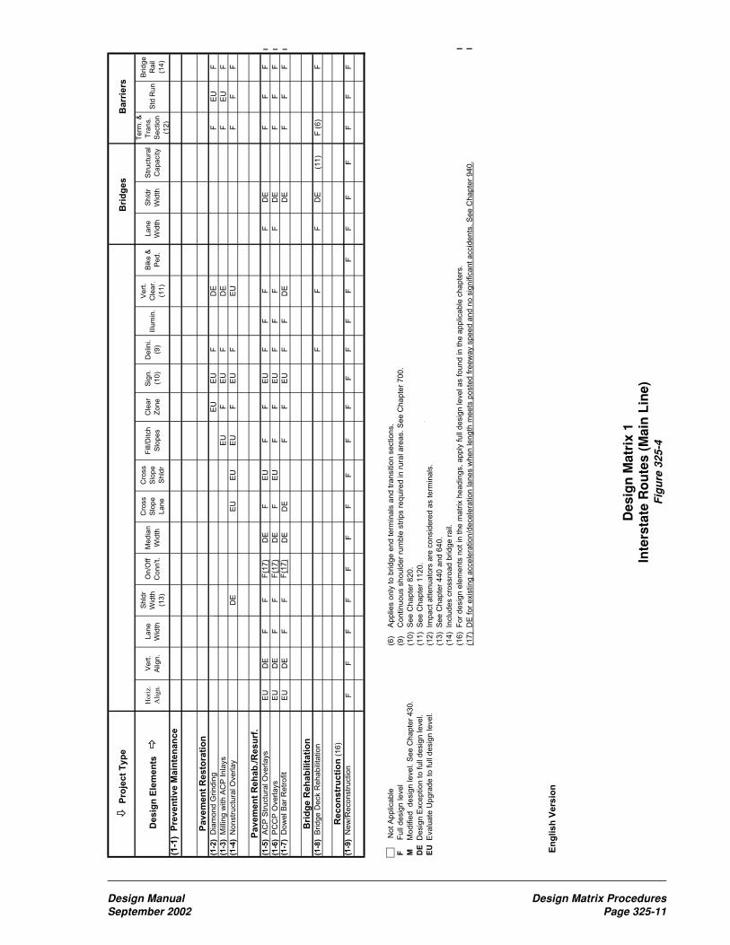
P
roje
ct
Ty
pe
Bri
dg
es
Ba
rrie
rs
De
sig
n E
lem
en
ts
Hori
z.
Ali
gn.
Vert
.
Alig
n.
Lane
Wid
th
Shld
r
Wid
th
(13)
On/O
ff
Conn't.
Media
n
Wid
th
Cro
ss
Slo
pe
Lane
Cro
ss
Slo
pe
Shld
r
Fill
/Ditch
Slo
pes
Cle
ar
Zone
Sig
n.
(10)
Delin
i.
(9)
Illu
min
.
Vert
.
Cle
ar.
(11)
Bik
e &
Ped.
Lane
Wid
th
Shld
r
Wid
th
Str
uctu
ral
Capacity
Term
. &
Tra
ns.
Section
(12
)
Std
Run
Bridge
Rail
(14)
(1-1
) P
rev
en
tiv
e M
ain
ten
an
ce
Pa
ve
me
nt
Re
sto
rati
on
(1-2
) D
iam
ond G
rindin
gE
UE
UF
DE
FE
UF
(1-3
) M
illin
g w
ith A
CP
Inla
ys
EU
FE
UF
DE
FE
UF
(1-4
) N
onstr
uctu
ral O
verlay
DE
EU
EU
EU
FE
UF
EU
FF
F
Pa
ve
me
nt
Re
ha
b./
Re
su
rf.
(1-5
) A
CP
Str
uctu
ral O
verlays
EU
DE
FF
F(1
7)
DE
FE
UF
FE
UF
FF
FD
EF
FF
l
(1-6
) P
CC
P O
verlays
EU
DE
FF
F(1
7)
DE
FE
UF
FE
UF
FF
FD
EF
FF
l
(1-7
) D
ow
el B
ar
Retr
ofit
EU
DE
FF
F(1
7)
DE
DE
FF
EU
FF
DE
DE
FF
F l
Bri
dg
e R
eh
ab
ilit
ati
on
(1-8
) B
ridge D
eck R
ehabili
tation
FF
FD
E(1
1)
F (
6)
F
Re
co
ns
tru
cti
on
(16)
(1-9
) N
ew
/Reconstr
uction
FF
FF
FF
FF
FF
FF
FF
FF
FF
FF
F
N
ot A
pplic
able
(6)
A
pplie
s o
nly
to b
ridge e
nd term
inals
and tra
nsitio
n s
ections.
F F
ull
desig
n level
(9)
C
ontinuous s
hould
er
rum
ble
str
ips r
equired in r
ura
l are
as. S
ee C
hapte
r 700.
M M
odifie
d desig
n level. S
ee C
hapte
r 430.
(10)
See C
hapte
r 820.
DE
D
esig
n E
xception to full
desig
n level.
(11)
See C
hapte
r 1120.
EU
E
valu
ate
Upgra
de to full
desig
n level.
(12)
Im
pact attenuato
rs a
re c
onsid
ere
d a
s term
inals
.
(13)
See C
hapte
r 440 a
nd 6
40.
(14)
Inclu
des c
rossro
ad b
ridge r
ail.
(16)
For
desig
n e
lem
ents
not in
the m
atr
ix h
eadin
gs, apply
full
desig
n level as found in the a
pplic
able
chapte
rs.
l
(17)
DE
for
exis
ting a
ccele
ration/d
ecele
ration lanes w
hen length
meets
poste
d fre
ew
ay s
peed a
nd n
o s
ignific
ant accid
ents
. S
ee C
hapte
r 940.
l
En
gli
sh
Ve
rsio
n
Des
ign
Mat
rix
1In
ters
tate
Ro
ute
s (M
ain
Lin
e)F
igu
re 3
25-4
Design Manual Design Matrix ProceduresSeptember 2002 Page 325-11
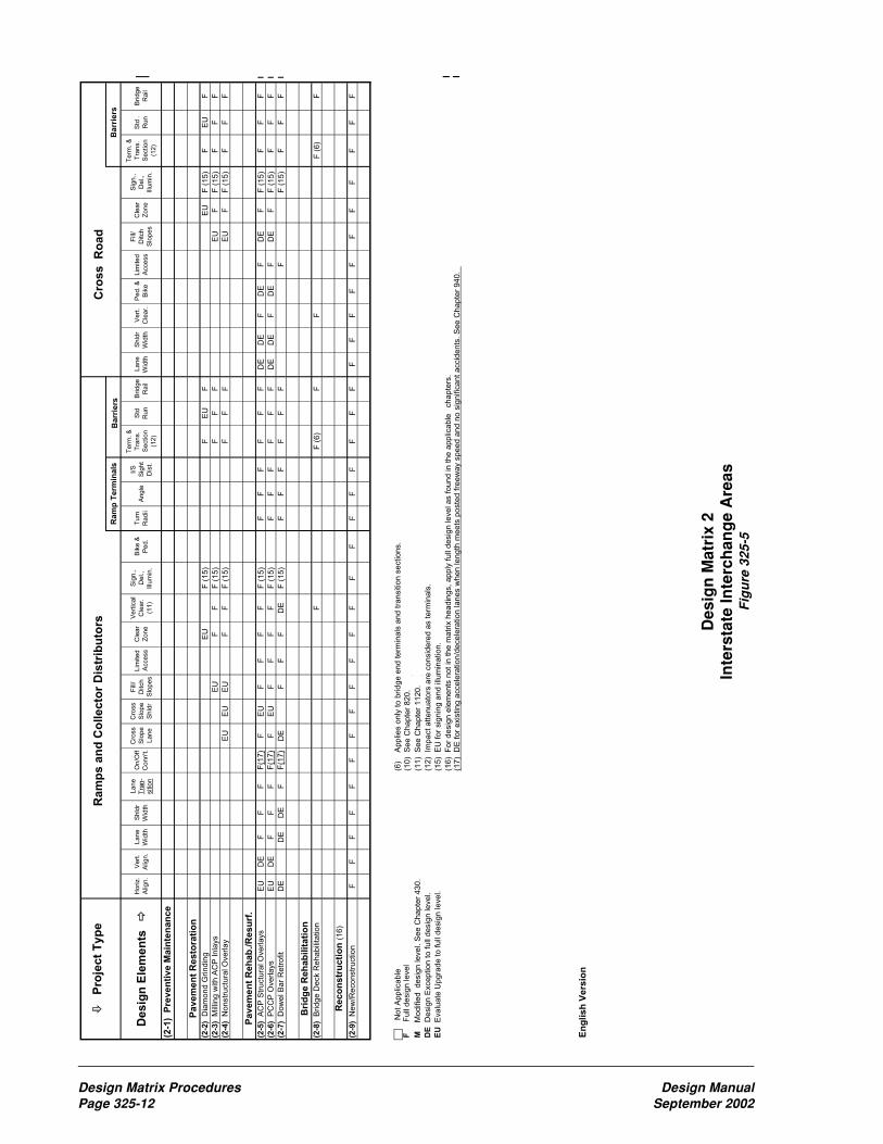
P
roje
ct
Typ
e R
am
ps a
nd
Co
llecto
r D
istr
ibu
tors
C
ross R
oad
Ra
mp
Te
rmin
als
B
arr
iers
Ba
rrie
rs
Desig
n E
lem
en
ts
Ho
riz.
Alig
n.
Ve
rt.
Alig
n.
La
ne
Wid
th
Sh
ldr
Wid
th
La
ne
Tra
n-
sitio
n
On
/Off
Co
nn
't.
Cro
ss
Slo
pe
La
ne
Cro
ss
Slo
pe
Sh
ldr
Fill
/
Ditch
Slo
pe
s
Lim
ite
d
Acce
ss
Cle
ar
Zo
ne
Ve
rtic
al
Cle
ar.
(11
)
Sig
n.,
De
l.,
Illu
min
.
Bik
e &
Pe
d.
Tu
rn
Ra
dii
An
gle
I/S
Sig
ht
Dis
t.
Te
rm.
&
Tra
ns.
Se
ctio
n
(12
)
Std
Ru
n
Brid
ge
Ra
il
La
ne
Wid
th
Sh
ldr
Wid
th
Ve
rt.
Cle
ar.
Pe
d.
&
Bik
e
Lim
ite
d
Acce
ss
Fill
/
Ditch
Slo
pe
s
Cle
ar
Zo
ne
Sig
n.,
De
l.,
Illu
min
.
Te
rm.
&
Tra
ns.
Se
ctio
n
(12
)
Std
.
Ru
n
Brid
ge
Ra
il
(2-1
) P
reven
tive M
ain
ten
an
ce
Pavem
en
t R
esto
rati
on
(2-2
) D
iam
on
d G
rin
din
gE
UF
(1
5)
FE
UF
EU
F (
15
)F
EU
F
(2-3
) M
illin
g w
ith
AC
P I
nla
ys
EU
FF
F (
15
)F
FF
EU
FF
(1
5)
FF
F
(2-4
) N
on
str
uctu
ral O
ve
rla
yE
UE
UE
UF
FF
(1
5)
FF
FE
UF
F (
15
)F
FF
Pavem
en
t R
eh
ab
./R
esu
rf.
(2-5
) A
CP
Str
uctu
ral O
ve
rla
ys
EU
DE
FF
FF
(17
)F
EU
FF
FF
F (
15
)F
FF
FF
FD
ED
EF
DE
FD
EF
F (
15
)F
FF
l
(2-6
) P
CC
P O
ve
rla
ys
EU
DE
FF
FF
(17
)F
EU
FF
FF
F (
15
)F
FF
FF
FD
ED
EF
DE
FD
EF
F (
15
)F
FF
l
(2-7
) D
ow
el B
ar
Re
tro
fit
DE
DE
DE
FF
(17
)D
EF
FF
DE
F (
15
)F
FF
FF
FF
F (
15
)F
FF
l
Bri
dg
e R
eh
ab
ilit
ati
on
(2-8
) B
rid
ge
De
ck R
eh
ab
ilita
tio
nF
F (
6)
FF
F (
6)
F
Reco
nstr
ucti
on
(1
6)
(2-9
) N
ew
/Re
co
nstr
uctio
n
FF
FF
FF
FF
FF
FF
FF
FF
FF
FF
FF
FF
FF
FF
FF
F
No
t A
pp
lica
ble
(6)
A
pp
lies o
nly
to
brid
ge
en
d t
erm
ina
ls a
nd
tra
nsitio
n s
ectio
ns.
F
F
ull
de
sig
n le
ve
l (1
0)
Se
e C
ha
pte
r 8
20
.
M
M
od
ifie
d
de
sig
n le
ve
l. S
ee
Ch
ap
ter
43
0.
(11
) S
ee
Ch
ap
ter
11
20
.
DE
D
esig
n E
xce
ptio
n t
o f
ull
de
sig
n le
ve
l.(1
2)
Im
pa
ct
att
en
ua
tors
are
co
nsid
ere
d a
s t
erm
ina
ls.
EU
E
va
lua
te U
pg
rad
e t
o f
ull
de
sig
n le
ve
l.(1
5)
EU
fo
r sig
nin
g a
nd
illu
min
atio
n.
(16
) F
or
de
sig
n e
lem
en
ts n
ot
in t
he
ma
trix
he
ad
ing
s,
ap
ply
fu
ll d
esig
n le
ve
l a
s f
ou
nd
in
th
e a
pp
lica
ble
ch
ap
ters
. l
(17
) D
E f
or
exis
tin
g a
cce
lera
tio
n/d
ece
lera
tio
n la
ne
s w
he
n le
ng
th m
ee
ts p
oste
d f
ree
wa
y s
pe
ed
an
d n
o s
ign
ific
an
t a
ccid
en
ts.
Se
e C
ha
pte
r 9
40
. l
En
glish
Vers
ion
Des
ign
Mat
rix
2In
ters
tate
Inte
rch
ang
e A
reas
Fig
ure
325
-5
Design Matrix Procedures Design ManualPage 325-12 September 2002

P
roje
ct
Typ
eB
RID
GE
SIN
TE
RS
EC
TIO
NS
BA
RR
IER
S
Desig
n E
lem
en
ts
H
ori
z.
Ali
gn
.
Ver
t.
Ali
gn
.
Lan
e
Wid
th
Sh
ldr
Wid
th
Lan
e
Tra
n-
siti
on
Med
ian
Wid
th
Cro
ss
Slo
pe
Lan
e
Cro
ss
Slo
pe
Sh
ldr
On
/Off
Co
nn
.
Fil
l/
Dit
ch
Slo
pes
Acc
ess
(3)
Cle
ar
Zo
ne
Sig
n.,
Del
.,
Illu
min
.
Bas
ic
Saf
ety
Bik
e &
Ped
.
Lan
e
Wid
th
Sh
ldr
Wid
th
Ver
tica
l
Cle
ar-
ance
Str
uct
ura
l
Cap
acit
y
Tu
rn
Rad
iiA
ng
leS
igh
t
Dis
t.
Ter
m.
&
Tra
ns.
Sec
tio
n
(12
)
Std
Ru
n
Bri
dg
e
Rai
l
Pre
serv
ati
on
Ro
ad
wa
y
(3-1
) N
on
-In
ters
tate
Fre
ew
ay
DE
/FD
E/F
DE
/FD
E/F
DE
/FD
E/F
DE
/FD
E/F
DE
/FD
E/F
DE
/FB
BD
E/F
DE
/FF
BB
F
(3-2
) A
CP
/PC
CP
/BS
T
Ove
rla
ys
DE
/MD
E/M
DE
/MD
E/M
DE
/FD
E/M
DE
/MD
E/M
DE
/FD
E/M
BB
DE
/MD
E/M
F
B
BB
F
(3-3
) R
ep
l. A
CP
w/
PC
CP
at
I/S
DE
/MD
E/M
EU
/ME
U/M
DE
/FD
E/M
EU
/MD
E/M
DE
/MB
BD
E/M
DE
/MF
BB
BF
Str
uc
ture
s
(3-4
) B
rid
ge
Re
pla
ce
me
nt
F (
2)
F (
2)
F (
2)
F (
2)
FF
(2
)F
(2
)F
(2
)F
(2
)F
(2
)F
FF
F (
2)
F (
2)
FF
(1
1)
F (
2)
F (
2)
FF
FF
(3-5
) B
rid
ge
De
ck
Re
ha
b.
BB
FB
(6
)F
Imp
rovem
en
ts (
16)
Mo
bil
ity
(3-6
) N
on
-In
ters
tate
Fre
ew
ay
FF
FF
FF
FF
FF
FF
FF
FF
FF
(1
1)
FF
FF
FF
(3-7
) U
rba
nF
(2
)F
(2
)F
(2
)F
(2
)F
F (
2)
F (
2)
F (
2)
F (
2)
F (
2)
FF
FF
F (
2)
F (
2)
FF
(1
1)
F (
2)
F (
2)
FF
FF
(3-8
) R
ura
lF
(2
)F
(2
)F
(2
)F
(2
)F
F (
2)
F (
2)
F (
2)
F (
2)
F (
2)
FF
FF
F (
2)
F (
2)
FF
(1
1)
F (
2)
F (
2)
FF
FF
(3-9
) H
OV
F (
2)
F (
2)
F (
2)
F (
2)
FF
(2
)F
(2
)F
(2
)F
(2
)F
(2
)F
FF
FF
(2
)F
(2
)F
F (
11
)F
(2
)F
(2
)F
FF
F
(3-1
0)
Bik
e/P
ed
. C
on
ne
ctivity
(5)
(5)
(5)
(5)
(5)
(5)
(5)
(5)
(5)
(5)
(5)
F(5
)(5
)(5
)(5
)(5
)(5
)(5
)(5
)(5
)(5
)
Sa
fety
(3-1
1)
No
n-I
nte
rsta
te F
ree
way
FF
FF
FF
FF
FF
FF
FF
FF
FF
FF
FF
F
(3-1
2)
All
Oth
ers
(1
) M
(4
)M
(4
)M
(4
)M
(4
)F
M (
4)
M (
4)
M (
4)
M (
4)
M (
4)
EU
/FF
FF
M (
4)
M (
4)
FM
(4
)M
(4
)F
FF
F
Ec
on
om
ic D
ev
elo
pm
en
t
(3-1
3)
Fre
igh
t &
Go
od
s (
Fro
st
Fre
e)
(8)
F (
2)
F (
2)
F (
2)
F (
2)
FF
(2
)F
(2
)F
(2
)F
(2
)F
(2
)E
U/F
FB
EU
DE
/FD
E/F
FF
(1
1)
EU
/FE
U/F
EU
/FF
FF
(3-1
4)
4-L
an
e T
run
k S
yste
mF
FF
FF
FF
FF
FF
FF
FF
FF
F (
11
)F
FF
FF
F
(3-1
5)
Re
st
Are
as (
Ne
w)
FF
FF
FF
FF
FF
FF
FF
FF
FF
(1
1)
FF
FF
FF
(3-1
6)
Brid
ge
Re
str
ictio
ns
F (
2)
F (
2)
F (
2)
F (
2)
FF
(2
)F
(2
)F
(2
)F
(2
)F
(2
)F
FE
UF
(2
)F
(2
)F
F (
11
)F
(2
)F
(2
)F
FF
F
(3-1
7)
Bik
e R
ou
tes (
Sh
ldrs
)E
U/M
(7)
EU
/FE
U/M
EU
/MB
BF
EU
/ME
U/M
FB
FB
EU
/F
No
t A
pp
lica
ble
(1)
C
olli
sio
n R
ed
uctio
n (
HA
L,
HA
C,
PA
L),
or
Co
llisio
n P
reve
ntio
n (
Ris
k,
At
Gra
de
Re
mo
va
l, S
ign
aliz
atio
n &
Ch
an
ne
liza
tio
n).
S
pe
cific
de
ficie
ncie
s t
ha
t
F
F
ull
de
sig
n le
ve
l
cre
ate
d t
he
pro
ject
mu
st
be
up
gra
de
d t
o d
esig
n le
ve
l a
s s
tate
d in
th
e m
atr
ix.
M
M
od
ifie
d
de
sig
n le
ve
l. S
ee
Ch
ap
ter
43
0.
(2)
M
od
ifie
d d
esig
n le
ve
l m
ay a
pp
ly b
ase
d o
n a
co
rrid
or
or
pro
ject
an
aly
sis
. S
ee
32
5.0
2.
B
B
asic
de
sig
n le
ve
l.
Se
e C
ha
pte
r 4
10
.(3
)
If d
esig
na
ted
in
Lim
ite
d A
cce
ss M
aste
r P
lan
ap
ply
lim
ite
d a
cce
ss s
tan
da
rds,
if
no
t a
cce
ss m
an
ag
em
en
t sta
nd
ard
s a
pp
ly.
Se
e C
ha
pte
r 9
20
.
DE
D
esig
n E
xce
ptio
n(4
)
Fu
ll d
esig
n le
ve
l m
ay a
pp
ly b
ase
d o
n a
co
rrid
or
or
pro
ject
an
aly
sis
. S
ee
32
5.0
2.
EU
E
va
lua
te U
pg
rad
e
(5)
F
or
bik
e/p
ed
estr
ian
de
sig
n s
ee
Ch
ap
ters
10
20
an
d 1
02
5.
(6)
A
pp
lies o
nly
to
brid
ge
en
d t
erm
ina
l a
nd
tra
nsitio
n s
ectio
ns.
(7)
4
ft
min
imu
m s
ho
uld
ers
.
(8)
I
f a
ll w
ea
the
r str
uctu
re c
an
be
ach
ieve
d w
ith
sp
ot
dig
ou
ts a
nd
ove
rla
y,
Mo
difie
d D
esig
n L
eve
l A
pp
lies.
(11
) S
ee
Ch
ap
ter
11
20
.
(12
) I
mp
act
att
en
ua
tors
are
co
nsid
ere
d a
s t
erm
ina
ls.
(16
) F
or
de
sig
n e
lem
en
ts n
ot
in t
he
ma
trix
he
ad
ing
s,
ap
ply
fu
ll d
esig
n le
ve
l a
s f
ou
nd
in
th
e a
pp
lica
bl ec
ha
pte
rs.
l
En
glish
Vers
ion
Des
ign
Mat
rix
3N
HS
Ro
ute
s (M
ain
Lin
e)F
igu
re 3
25-6
Design Manual Design Matrix ProceduresSeptember 2002 Page 325-13

P
roje
ct
Ty
pe
Ra
mp
s a
nd
Co
lle
cto
r D
istr
ibu
tors
Cro
ss
R
oa
d
Ra
mp
Te
rmin
als
Ba
rrie
rsB
arr
iers
Des
ign
Ele
men
ts
Ho
riz.
Alig
n.
Ve
rt.
Alig
n.
La
ne
Wid
th
Sh
ldr
Wid
th
La
ne
Tra
n-
sitio
n
On
/Off
Co
nn
.
Cro
ss
Slo
pe
La
ne
Cro
ss
Slo
pe
Sh
ldr
Fill
/
Ditch
Slo
pe
s
Acce
ss
(3)
Cle
ar
Zo
ne
Sig
n,
De
l.,
Illu
min
.
Ba
sic
Sa
fety
Bik
e &
Pe
d.
Tu
rn
Ra
dii
An
gle
I/S
Sig
ht
Dis
t.
Te
rm.
&
Tra
ns.
Se
ctio
n
(12
)
Std
Ru
n
Brid
ge
Ra
il
La
ne
Wid
th
Sh
ldr
Wid
th
Ve
rt.
Cle
ar.
Pe
d.
&
Bik
e
Acce
ss
(3)
Sig
n.,
De
l.,
Illu
min
.
Fill
/
Ditch
Slo
pe
s
Cle
ar
Zo
ne
Ba
sic
Sa
fety
Te
rm.
&
Tra
ns.
Se
ctio
n
(12
)
Std
.
Ru
n
Brid
ge
Ra
il
Pre
se
rva
tio
nR
oa
dw
ay
(4-1
) N
on
-In
ters
tate
Fre
ew
ay
DE
/FD
E/F
DE
/FD
E/F
DE
/FD
E/F
DE
/FD
E/F
DE
/FD
E/F
BB
DE
/FD
E/F
DE
/FB
BF
DE
/FD
E/F
FB
DE
/FB
BB
F
(4-2
) A
CP
/PC
CP
/BS
TB
BB
BB
FF
BB
BB
F
Ove
rla
ys R
am
ps
Str
uc
ture
s
(4-3
) B
rid
ge
Re
pla
ce
me
nt
F (
2)
F (
2)
F (
2)
F (
2)
FF
(2
)F
(2
)F
(2
)F
(2
)F
FF
FF
FF
FF
FF
(2
)F
(2
)F
FF
FF
(2
)F
FF
F
(4-4
) B
rid
ge
De
ck R
eh
ab
B
BB
(6
)F
F
BB
B (
6)
F
Imp
rov
em
en
ts (1
6)
Mo
bil
ity
(4-5
) N
on
-In
ters
tate
Fre
ew
ay
FF
FF
FF
FF
FF
FF
FF
FF
FF
FF
FF
FF
FF
FF
FF
(4-6
) U
rba
nF
(2
)F
(2
)F
(2
)F
(2
)F
F (
2)
F (
2)
F (
2)
F (
2)
FF
FF
F (
2)
F (
2)
FF
FF
F (
2)
F (
2)
FF
FF
F (
2)
FF
FF
(4-7
) R
ura
lF
(2
)F
(2
)F
(2
)F
(2
)F
F (
2)
F (
2)
F (
2)
F (
2)
FF
FF
F (
2)
F (
2)
FF
FF
F (
2)
F (
2)
FF
FF
F (
2)
FF
FF
(4-8
) H
OV
By P
ass
F (
2)
F (
2)
F (
2)
F (
2)
FF
(2
)F
(2
)F
(2
)F
(2
)F
FF
FF
(2
)F
(2
)F
FF
FF
(2
)F
(2
)F
FF
FF
(2
)F
FF
F
(4-9
) B
ike
/Pe
d.
Co
nn
ectivity
(5)
(5)
(5)
(5)
(5)
(5
)(5
)(5
)(5
)(5
)(5
)F
(5)
(5)
(5)
(5)
(5)
(5)
(5)
(5)
(5)
F
(5)
(5)
(5)
(5)
(5)
Sa
fety
(4-1
0)
No
n-I
nte
rsta
te F
ree
wa
yF
FF
FF
FF
FF
FF
FF
FF
FF
FF
FF
FF
FF
FF
F
(4-1
1)
At
Gra
de
(1
)F
(2
)F
(2
)F
(2
)F
(2
)F
F (
2)
F (
2)
F (
2)
F (
2)
FF
FF
F (
2)
F (
2)
FF
FF
F (
2)
F (
2)
FF
FF
F (
2)
FF
FF
(4-1
2)
All
Oth
ers
(1
) M
(4
)M
(4
)M
(4
)M
(4
)F
M (
4)
M (
4)
M (
4)
M (
4)
EU
/FF
FM
(4
)M
(4
)F
F
FF
F (
2)
F (
2)
F
EU
/FF
M
(4
)F
FF
F
Ec
on
om
ic D
ev
elo
pm
en
t
(4-1
3)
Fo
ur-
La
ne
Tru
nk S
yste
mF
FF
FF
FF
FF
FF
FF
FF
FF
FF
FF
FF
FF
FF
FF
N
ot
Ap
plic
ab
le(1
)
Co
llisio
n R
ed
uctio
n (
HA
L,
HA
C,
PA
L),
or
Co
llisio
n P
reve
ntio
n (
Ris
k,
Sig
na
liza
tio
n &
Ch
an
ne
liza
tio
n).
Sp
ecific
de
ficie
ncie
s t
ha
t
F
F
ull
de
sig
n le
ve
l
cre
ate
d t
he
pro
ject
mu
st
be
up
gra
de
d t
o d
esig
n le
ve
l a
s s
tate
d in
ma
trix
.
M
M
od
ifie
d
de
sig
n le
ve
l. S
ee
Ch
ap
ter
43
0.
(2)
M
od
ifie
d d
esig
n le
ve
l m
ay a
pp
ly b
ase
d o
n a
co
rrid
or
or
pro
ject
an
aly
sis
. S
ee
32
5.0
2.
B
B
asic
de
sig
n le
ve
l. S
ee
Ch
ap
ter
41
0.
(3)
If
de
sig
na
ted
in
lim
ite
d a
cce
ss m
aste
r p
lan
ap
ply
lim
ite
d a
cce
ss s
tan
da
rds,
if n
ot
acce
ss m
an
ag
em
en
t sta
nd
ard
s a
pp
ly.
Se
e C
ha
pte
r 9
20
.
DE
D
esig
n E
xce
ptio
n
(4)
F
ull
de
sig
n le
ve
l m
ay a
pp
ly b
ase
d o
n a
co
rrid
or
or
pro
ject
an
aly
sis
. S
ee
32
5.0
2.
EU
E
va
lua
te U
pg
rad
e
(5)
F
or
bik
e/p
ed
estr
ian
de
sig
n s
ee
Ch
ap
ters
10
20
an
d 1
02
5.
(6)
A
pp
lies o
nly
to
brid
ge
en
d t
erm
ina
ls a
nd
tra
nsitio
n s
ectio
ns.
(7)
4
ft
min
imu
m s
ho
uld
ers
.
(12
) I
mp
act
att
en
ua
tors
are
co
nsid
ere
d a
s t
erm
ina
ls.
(16
) F
or
de
sig
n e
lem
en
ts n
ot
in t
he
ma
trix
he
ad
ing
s,
ap
ply
fu
ll d
esig
n le
ve
l a
s f
ou
nd
in
th
e a
pp
lica
ble
ch
ap
ters
. l
En
gli
sh
Ve
rsio
n
Des
ign
Mat
rix
4N
on
-In
ters
tate
Inte
rch
ang
e A
reas
Fig
ure
325
-7
Design Matrix Procedures Design ManualPage 325-14 September 2002
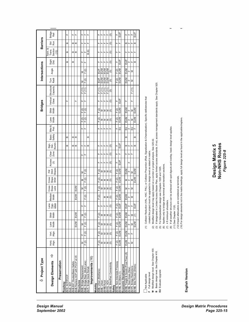
P
roje
ct
Ty
pe
B
rid
ges
Inte
rsecti
on
sB
arr
iers
De
sig
n E
lem
en
tsH
oriz.
Alig
n.
Ve
rt.
Alig
n.
La
ne
Wid
th
Sh
ldr
Wid
th
La
ne
Tra
n-
sitio
n
Me
dia
n
Wid
th
Cro
ss
Slo
pe
La
ne
Cro
ss
Slo
pe
Sh
ldr
Fill
/
Ditch
Slo
pe
s
Acce
ss
(3)
Cle
ar
Zo
ne
Sig
n,
De
l.,
Illu
min
.
Ba
sic
Sa
fety
Bik
e &
Pe
d.
La
ne
Wid
th
Sh
ldr
Wid
th
Ve
rtic
al
Cle
ar.
Str
uctu
ral
Ca
pa
city
Tu
rn
Ra
dii
An
gle
Sig
ht
Dis
t.
Te
rm.
&
Tra
ns.
Se
ctio
n
(12
)
Std
Ru
n
Brid
ge
Ra
il
Pre
se
rva
tio
nR
oa
dw
ay
(5-1
) A
CP
/PC
CP
BB
F
BB
BF
(5-2
) B
ST
(5-3
) B
ST
Ro
ute
s/B
asic
Sa
fety
BB
B
BB
F
(5-4
) R
ep
lace
AC
P w
ith
PC
CP
at
I/S
EU
/ME
U/M
EU
/ME
U/M
BB
FB
BF
Str
uc
ture
s
(5-5
) B
rid
ge
Re
pla
ce
me
nt
M
F
M
M
FM
M
M
F
F
FF
(2
)
F
(2
)F
F (
11
)M
M
F
FF
F
(5-6
) B
rid
ge
Re
pl. (
Mu
lti-L
an
e)
F (
2)
F (
2)
F (
2)
F (
2)
FF
(2
)F
(2
)F
(2
)F
(2
)F
F
FF
(2
)F
(2
)F
F (
11
)F
(2
) F
(2
)F
F
FF
(5-7
) B
rid
ge
De
ck R
eh
ab
BB
B (
6)
FF
Imp
rov
em
en
ts (
16
)
Mo
bil
ity
(5-8
) U
rba
n (
Mu
ltila
ne
)F
(2
)F
(2
)F
(2
)F
(2
)F
F (
2)
F (
2)
F (
2)
F (
2)
FF
FF
F (
2)
F (
2)
FF
(1
1)
EU
/FE
U/F
FF
FF
(5-9
) U
rba
nM
MM
MF
MM
MF
FF
FM
MF
F (
11
)E
U/M
EU
/MF
FF
F
(5-1
0)
Ru
ral
MM
MM
FM
MM
MF
FF
FM
MF
F (
11
)E
U/M
EU
/MF
FF
F
(5-1
1)
HO
VM
MM
MF
MM
MM
FF
FF
MM
FF
(1
1)
EU
/ME
U/M
FF
FF
(5-1
2)
Bik
e/P
ed
. C
on
ne
ctivity
(5)
(5)
(5)
(5)
(5)
(5)
(5)
(5)
(5)
(5)
(5)
(5)
F(5
)(5
)(5
)(5
)(5
)(5
)(5
)(5
)(5
)(5
)
Sa
fety
(5-1
3)
No
n-I
nte
rsta
te F
ree
wa
yF
(2
)F
(2
)F
(2
)F
(2
)F
(2
)F
(2
)F
(2
)F
(2
)F
(2
)F
FF
FF
(2
)F
(2
)F
F (
2)
F (
2)
FF
FF
(5-1
4)
All
Oth
ers
(1
) E
U/M
EU
/ME
U/M
EU
/ME
U/F
EU
/ME
U/M
EU
/ME
U/M
EU
/FF
EU
/FE
UE
U/M
EU
/ME
U/F
EU
/ME
U/M
EU
/FF
FE
U/F
Ec
on
om
ic D
ev
elo
pm
en
t
(5-1
5)
Fre
igh
t &
Go
od
s (
Fro
st
Fre
e)
(8)
EU
/ME
U/M
EU
/ME
U/M
EU
/FE
U/M
MM
EU
/MF
BB
EU
EU
/M E
U/M
FE
U/M
EU
/ME
U/F
FB
F
(5-1
6)
Re
st
Are
as (
Ne
w)
FF
FF
FF
FF
FF
FF
FF
FF
FF
FF
F
(5-1
7)
Brid
ge
Re
str
ictio
ns
M
F
M
M
FM
M
M
M
F
FE
UM
M
F
F (
11
)M
M
FF
FF
(5-1
8)
Bik
e R
ou
tes (
Sh
ldrs
)E
U/M
(7)
EU
/FE
U/M
EU
/MB
BF
EU
/ME
U/M
BF
BE
U/F
N
ot
Ap
plic
ab
le(1
)
Co
llisio
n R
ed
uctio
n (
HA
L,
HA
C,
PA
L),
or
Co
llisio
n P
reve
ntio
n (
Ris
k,
Sig
na
liza
tio
n &
Ch
an
ne
liza
tio
n).
Sp
ecific
de
ficie
ncie
s t
ha
t
F
F
ull
de
sig
n le
ve
l
cre
ate
d t
he
pro
ject
mu
st
be
up
gra
de
d t
o d
esig
n le
ve
l a
s s
tate
d in
ma
trix
.
M
Mo
difie
d d
esig
n le
ve
l. S
ee
Ch
ap
ter
43
0.
(2)
M
od
ifie
d d
esig
n le
ve
l m
ay a
pp
ly b
ase
d o
n a
co
rrid
or
or
pro
ject
an
aly
sis
. S
ee
32
5.0
2.
B
B
asic
de
sig
n le
ve
l. S
ee
Ch
ap
ter
41
0.
(3)
If
de
sig
na
ted
in
Lim
ite
d A
cce
ss M
aste
r P
lan
, a
pp
ly lim
ite
d a
cce
ss s
tan
da
rds.
If n
ot,
acce
ss m
an
ag
em
en
t sta
nd
ard
s a
pp
ly.
Se
e C
ha
pte
r 9
20
.
EU
E
va
lua
te U
pg
rad
e
(5)
F
or
bik
e/p
ed
estr
ian
de
sig
n s
ee
Ch
ap
ters
10
20
an
d 1
02
5.
(6)
A
pp
lies o
nly
to
brid
ge
en
ds t
erm
ina
l a
nd
tra
nsitio
n s
ectio
ns.
(7)
4
ft
min
imu
m s
ho
uld
ers
.
(8)
If
all
we
ath
er
str
uctu
re c
an
be
ach
ieve
d w
ith
sp
ot
dig
ou
ts a
nd
ove
rla
y,
ba
sic
de
sig
n le
ve
l a
pp
lies.
l
(11
) S
ee
Ch
ap
ter
11
20
.
(12
) Im
pa
ct
att
en
ua
tors
are
co
nsid
ere
d a
s t
erm
ina
ls.
(16
) F
or
de
sig
n e
lem
en
ts n
ot
in t
he
ma
trix
he
ad
ing
s,
ap
ply
fu
ll d
esig
n le
ve
l a
s f
ou
nd
in
th
e a
pp
lica
ble
ch
ap
ters
. l
En
gli
sh
Ve
rsio
n
Des
ign
Mat
rix 5
Non
-NH
S R
oute
sFi
gure
325
-8
Design Manual Design Matrix ProceduresSeptember 2002 Page 325-15


Design Manual Minor Operational Enhancement ProjectsSeptember 2002 Page 340-1
Minor Operational340 Enhancement Projects
340.01 General340.02 References340.03 Definitions340.04 Minor Operational Enhancement
Matrix Procedures340.05 Selecting a Minor Operational
Enhancement Matrix340.06 Project Type340.07 Using a Minor Operational
Enhancement Matrix340.08 Project Approval340.09 Documentation
340.01 GeneralThis chapter complements Chapter 325 byproviding guidance for development of minoroperational enhancement projects. Refer toChapter 325 for guidance in development ofpreservation and improvement projects. Theminor operational enhancement matricescontained in this chapter identify the designlevel(s) for a project, the associated approvallevel, and the documentation requirements forthe various project elements. These matricesaddress the most common minor operationalenhancement projects and focus on the elementsof greatest concern during project development.
Minor enhancement projects are often categorizedas low-cost, quick-fixes to improve the operationof the highway system. These enhancements aremost often installed by state forces through workorders, but may be accomplished through: achange order to an existing state contract,agreements with local agencies, a Q Programfunded bid item within a larger improvementproject, or a stand-alone state contract fundedentirely through the Q Program. An importantcharacteristic of these projects is the ability toquickly develop and implement them withouta cumbersome approval process. Balanced withthat is a need to apply consistency in designpolicies and guidelines in the development andapproval processes. Therefore, the intent of thischapter is to clarify the design guidelines anddocumentation requirements for minor
operational enhancement projects without undulyimpeding the process.
The objective of the Q Program is to maximizehighway transportation system safety andefficiency through a statewide program focusedon the WSDOT business function for “TrafficOperations.” It is the smallest of the four majorhighway programs that comprise the HighwaySystem Plan (i.e. Improvement, Maintenance,Preservation, and Traffic Operations). Elementswithin the Q Program include: Q1 - ManagementSupport, Q2 - Operations and Low CostEnhancements, and Q3 - Special AdvancedTechnology Projects. Large capital improvementprojects developed for the Q3 subprogram arebeyond the scope of this chapter. Normally, theseprojects are developed using Design Manualguidelines for Preservation and ImprovementProgram projects. Consult the HeadquartersTraffic Office for guidance when designing Q3subprogram projects.
The minor operational enhancement matricesconsisting of three tables are identified by routetype. One of the matrices applies to Interstate andNHS freeways, one applies to NHS Nonfreewayroutes, and the third matrix applies to Non-NHSroutes.
340.02 ReferencesRevised Code of Washington (RCW) 47.28.030,Contracts —State forces —Monetary limits —Small businesses, minority, and womencontractors —Rules.Chart of Accounts, M 13-02, WSDOT
340.03 DefinitionsThe National Highway System (NHS) routes areidentified in Chapter 325.
The term freeway applies to multilane, dividedhighways with full access control.
The minor operational enhancement projectsusually originate from the Q2 component of theQ Program and are quick responses to implementlow cost improvements.

Minor Operational Enhancement Projects Design ManualPage 340-2 September 2002
Projects are typically narrow in scope, and focuson improvements to traffic operations, andmodifications to traffic control devices. Guidanceon the type of work included in the Q subprogramsis in the Chart of Accounts (M 13-02).
(1) Project TypesRegulatory projects include actions undertakento manage or regulate traffic conflict, movements,and use of the roadway. Potential project types inthis category include revisions to speed limits,parking restrictions, turn restrictions, truckrestrictions, signal operations, unsignalizedintersection control, intersection lane use control,ramp meters, no passing zones, crosswalks,special traffic control schemes, and lane userestrictions.
Driver guidance projects are actions to improvedriver guidance, clarify options, or reduce hazardin the roadway setting. Potential project typesinclude revisions to, informational signs, warningsigns, lighting and supplemental illumination,supplemental delineation, glare screen, signals,roadside guidance, and intelligent transportationsystems (ITS).
Pavement widening projects are expansion ofthe roadway surface for vehicular use and mayinvolve earthwork, drainage, and pavingelements. Potential project types are:
• Turn lane — Addition of a new channelizedturn bay at an intersection.
• Pullout — Pavement widening to provideauxiliary highway uses including transitstops, Washington State Patrol (WSP)enforcement pullouts, snow chain-up areas,and maintenance vehicle turnouts.
• Expansion — Widen at intersection corners,lengthen existing channelized turn bay,widening shoulders, and flattening approachtaper. This type of work is not anticipated formain line sections on Interstate freeways.
• Median crossover — Restricted-use mediancrossover on separated highways foremergency or maintenance use.
Rechannelize existing pavement projects alterthe use of the roadway without additionalwidening. These projects may add, delete, or
modify channelization features, and may includereduction of existing shoulder or lane widths.Potential project types are:
• Pavement markings — Develop addedstorage, additional lanes, or altered lanealignment. This work may modify tapersor radii, modify painted islands, channelizebicycle lanes, or preferential-use lanes orshoulders.
• Raised channelization — New or alteredraised curbing to channelization islands toenhance guidance, curtail violation or misuse,or introduce access control.
Nonmotorized facilities projects add adjacentroadside features for bicycle or pedestrian use.Potential project types are:
• Sidewalk — Installation of sidewalks, whichmight involve preserving existing shoulder,or converting some portion of existingshoulder for use as a new sidewalk.
• Walkway — Adds to the existing roadway’soverall width to provide a wider walkableshoulder.
• Separated Trails — Class 1 separated bikelane or pedestrian paths on independentalignment or parallel to the highway.
• Spot Improvement — Installation of ADAsidewalk curb cuts, new pedestrian landings,sidewalk bulbs at intersections, or new orrevised trailhead features.
Roadside projects are modifications to roadsidefeatures for safety purposes. Potential projecttypes are:
• Cross section — Altering roadway crosssections to address clear zone hazard or sightdistance concern such as slope flattening,recontour a ditch, closing a ditch withculvert, or removal of hazard.
• Protection — Installation of hazard protectionfor clear zone mitigation including guardrail,barrier, earth berm, and impact attenuator.
• New object — Placement of new hardware orfixed object within clear zone unable to meetbreakaway criteria.

Design Manual Minor Operational Enhancement ProjectsSeptember 2002 Page 340-3
(2) Design ElementsThe following elements are shown on the minoroperational enhancement matrices. If full designlevel applies see the chapters listed below. Ifmodified design level applies, see Chapter 430.
Sight Distance Refers to any combination ofstopping sight distance, decision sight distance,passing sight distance, and intersection sightdistance. See Chapters 650 and 910 fordefinitions and guidance.
Lane Width See Chapter 325 for definition.
Lane Transition See Chapter 325for definition.
Shoulder Width See Chapter 325 for definition.
Fill/Ditch Slope See Chapter 325 for definition.
Clear Zone See Chapter 325 for definition.
Ramp Sight Distance Refers to anycombination of stopping sight distance, decisionsight distance, and intersection sight distance.See Chapters 650 and 910 for definitions andguidance.
Ramp Lane Width is the lane width for rampalignments. See Lane Width definition.
Ramp Lane and Shoulder Taper is the laneand shoulder taper applied to a ramp alignment.See definition for Lane and Shoulder Taper.Also see Chapter 940.
Ramp Shoulder Width is the shoulder width fora ramp alignment. See Shoulder Width definition.
Ramp Fill/Ditch Slopes is the fill/ditch slopealong a ramp alignment. See Fill/Ditch Slopedefinition in Chapter 325.
Ramp Clear Zone is the clear zone along aramp alignment. See Clear Zone definition inChapter 325.
Ramp Terminals or Intersections TurningRadii See Chapter 910 for definition.
Ramp Terminals or Intersections AngleSee Chapter 910 for definition.
Ramp Terminals or Intersections SightDistance See Chapter 910 for definition.
Pedestrian and Bike refers to the facilitiesalong a route for accommodation of pedestriansand/or bicycles. See Chapter 1020 for bicyclesand Chapter 1025 for pedestrians.
Crossroads at Ramps Lane Width is the lanewidth on a crossing alignment intersected by aramp. See Lane Width definition.
Crossroads at Ramps Shoulder Width isthe shoulder width on a crossing alignmentintersected by a ramp. See Lane Width definition.
Crossroads at Ramps Pedestrian andBike refers to the facilities on a crossing align-ment intersected by a ramp, for accommodationof pedestrians and/or bicycles. See Pedestrianand Bike definition.
Crossroads at Ramps Fill/Ditch Slopesis the fill/ditch slope along a crossroad intersectedby a ramp. See Fill/Ditch Slope definition.
Crossroads at Ramps Clear Zone is the clearzone along a crossroad intersected by a ramp.See Clear Zone definition.
Barriers Terminal and Transition SectionSee Chapter 325 for definition.
Barriers Standard Run See Chapter 325 fordefinition.
340.04 Minor OperationalEnhancement Matrix ProceduresDuring project definition and design, thefollowing steps are used to select and applythe appropriate minor operational enhancementmatrix. Each step is further explained in thischapter.
• Select a minor operational enhancementmatrix by identifying the route: Interstate/NHS Freeway, NHS nonfreeway, or non-NHS.
• Within the minor operational enhancementmatrix, select the row by the type of work.
• Use the minor operational enhancementmatrix to determine the documentation andapproval levels for the various designelements in the project. Apply theappropriate design levels and documentthe design decisions as required by thischapter and Chapter 330.
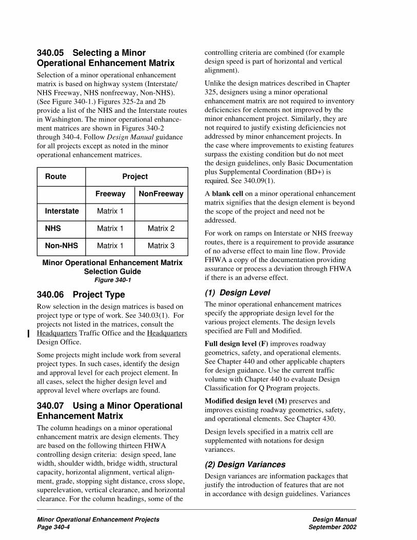
340.05 Selecting a MinorOperational Enhancement MatrixSelection of a minor operational enhancementmatrix is based on highway system (Interstate/NHS Freeway, NHS nonfreeway, Non-NHS).(See Figure 340-1.) Figures 325-2a and 2bprovide a list of the NHS and the Interstate routesin Washington. The minor operational enhance-ment matrices are shown in Figures 340-2through 340-4. Follow Design Manual guidancefor all projects except as noted in the minoroperational enhancement matrices.
Route Project
Freeway NonFreeway
Interstate Matrix 1
NHS Matrix 1 Matrix 2
Non-NHS Matrix 1 Matrix 3
Minor Operational Enhancement MatrixSelection Guide
Figure 340-1
340.06 Project TypeRow selection in the design matrices is based onproject type or type of work. See 340.03(1). Forprojects not listed in the matrices, consult theHeadquarters Traffic Office and the HeadquartersDesign Office.
Some projects might include work from severalproject types. In such cases, identify the designand approval level for each project element. Inall cases, select the higher design level andapproval level where overlaps are found.
340.07 Using a Minor OperationalEnhancement MatrixThe column headings on a minor operationalenhancement matrix are design elements. Theyare based on the following thirteen FHWAcontrolling design criteria: design speed, lanewidth, shoulder width, bridge width, structuralcapacity, horizontal alignment, vertical align-ment, grade, stopping sight distance, cross slope,superelevation, vertical clearance, and horizontalclearance. For the column headings, some of the
controlling criteria are combined (for exampledesign speed is part of horizontal and verticalalignment).
Unlike the design matrices described in Chapter325, designers using a minor operationalenhancement matrix are not required to inventorydeficiencies for elements not improved by theminor enhancement project. Similarly, they arenot required to justify existing deficiencies notaddressed by minor enhancement projects. Inthe case where improvements to existing featuressurpass the existing condition but do not meetthe design guidelines, only Basic Documentationplus Supplemental Coordination (BD+) isrequired. See 340.09(1).
A blank cell on a minor operational enhancementmatrix signifies that the design element is beyondthe scope of the project and need not beaddressed.
For work on ramps on Interstate or NHS freewayroutes, there is a requirement to provide assuranceof no adverse effect to main line flow. ProvideFHWA a copy of the documentation providingassurance or process a deviation through FHWAif there is an adverse effect.
(1) Design LevelThe minor operational enhancement matricesspecify the appropriate design level for thevarious project elements. The design levelsspecified are Full and Modified.
Full design level (F) improves roadwaygeometrics, safety, and operational elements.See Chapter 440 and other applicable chaptersfor design guidance. Use the current trafficvolume with Chapter 440 to evaluate DesignClassification for Q Program projects.
Modified design level (M) preserves andimproves existing roadway geometrics, safety,and operational elements. See Chapter 430.
Design levels specified in a matrix cell aresupplemented with notations for designvariances.
(2) Design VariancesDesign variances are information packages thatjustify the introduction of features that are notin accordance with design guidelines. Variances
Minor Operational Enhancement Projects Design ManualPage 340-4 September 2002

Design Manual Minor Operational Enhancement ProjectsSeptember 2002 Page 340-5
specified in minor operational enhancementproject cells include: Design Justification,Level 2, Level 3, or Level 4. See 340.09 fordetail on documentation requirements.
340.08 Project ApprovalProject approval for minor operationalenhancement projects authorizes expendituresfor the project. The state and/or region TrafficEngineer have the responsibility and authorityto authorize all expenditures for Q2 Low CostEnhancements. Delegation of design and/orexpenditure approval authority for Q Programfunded projects must be identified in writing fromthe appropriate Traffic Engineer to the personreceiving the delegated authority. Such writtendelegation must identify the specific conditionsfor which approval authority has been delegated.Design approval authority for PS&E contractscannot be delegated.
Mechanisms for project expenditure approvalvary with the types of projects and the costsinvolved.
• Minor-cost projects are projects normallyimplemented by state forces directed throughmaintenance task orders, within the monetarylimits established in RCW 47.28.030.Expenditure authority is granted by initialingthe work order.
• Mid-range projects include: all contractchange orders, local agency agreements,or Q Program bid items included in anImprovement or Preservation project,regardless of cost. Maintenance task ordersexceeding the monetary limits established inRCW 47.28.030 are included in this category.Expenditure authority is granted by initialingthe task order, change order, or agreementmemo.
• PS&E contracts are stand-alone contractsfunded through the Q Program for minoroperational enhancement projects. A DesignSummary/Approval memorandum must beprepared and signed by the region’s TrafficEngineer to approve a project in thiscategory. Figures 340-5a and 340-5b providea template for the approval memo.
Project development decisions and approvals for“Regulatory” and for “Driver Guidance” projectsreside within region or Headquarters TrafficOffices. Projects impacting roadway geometricfeatures in the “Pavement Widening,”“Rechannelizing Existing Pavement,”“Nonmotorized Facilities” or “Roadside”categories are developed jointly by the region’sTraffic Office and the region’s projectDevelopment Office. Depending on the routetype, the approval authority may involve theAssistant State Design Engineer and the FHWA.
340.09 DocumentationThe minor operational enhancementmatrices include a column that specifies thedocumentation levels for each project typelisted. The documentation levels are categorizedas Basic Documentation (BD) and BasicDocumentation plus Supplemental Coordination(BD+).
In all cases, the documentation must outlinethe rationale for the project and include backupinformation sufficient to support the designdecisions. Document the roadway configurationprior to implementation of a minor operationalenhancement project. Documentation is to beretained in a permanent retrievable file ata central location in each region.
(1) ProjectsBasic Documentation (BD) level appliesto regulatory or driver guidance projects.Documentation consists of an unstructuredcompilation of materials sufficient to validatethe designer’s decisions. Materials may include:meeting notes, printed e-mails, record of phoneconversations, copies of memos, correspondence,and backup data such as level of servicemodeling, accident data, and design drawings.A single narrative outlining the decision-makingprocess from start to finish is not required,provided that the materials retained in the filecan be traced to a decision consistent with theproject design. This level of documentationincludes a requirement for inputting the projectinformation into the TRaffic ACtion TrackingSystem (TRACTS) database at the conclusionof the project.

Minor Operational Enhancement Projects Design ManualPage 340-6 September 2002
Basic Documentation plus SupplementalCoordination (BD+) level applies to all projectsexcept regulatory or driver guidance projects.A more comprehensive evaluation of optionsand constraints is required for this documentationlevel. Documentation includes basicdocumentation with additional informationdescribing coordination efforts with otherWSDOT groups having a stake in the project.Document the coordination efforts with thefollowing disciplines: The Public, Environmental,Hydraulics, Local Programs, Maintenance,Materials, Program Management, Real EstateServices, Urban Mobility, and Utilities. This levelof documentation also includes a requirement forinputting the project information into theTRACTS database at the conclusion of theproject.
(2) Design DeviationsDesign Justification (DJ) is a written narrativesummarizing the rationale for introduction of afeature that varies from the applicable DesignManual guidelines. Include in the narrativesufficient information to describe the problem,the constraints, and the trade-offs at a level ofdetail that provides a defendable professionaljudgment. DJs are not intended to have the samelevel of formality as the Level 2, 3, and 4deviations. DJs may use written memos, e-mails,or documented discussions with the approvingtraffic authority. The region’s Traffic Engineerhas responsibility for approving DesignJustifications. The DJ documentation mustinclude the name and date of the approvingauthority. At the time the work order is approved,the region’s Project Development Engineer andthe Assistant State Design Engineer are to be sentinformational copies of the Design Justification,to provide them an opportunity to communicatetheir concerns. Comment on the informationalcopy is not mandatory and progress towardproject implementation does not wait on aresponse.
Level 2 documentation serves to justify adeviation to the specified design guidance.Within the document, summarize the project,the design guidelines, the proposed elementsthat vary from design guidelines, alternatives
analyzed, constraints and impacts of eachalternative, and the recommended alternative.Level 2 documentation requires joint approvalof the region’s Traffic Engineer and region’sProject Development Engineer. At the time thework order is approved, the Assistant StateDesign engineer is to be sent an informationalcopy of the Level 2 documentation to provide anopportunity to communicate concerns. Commenton the informational copy is not mandatory, andprogress toward project implementation does notwait on a response.
Level 3 documentation requirements includethe level 2 requirements, however the approvalprocess is through the region’s Traffic Engineer,and region’s Project Development Engineer withfinal approval from the Assistant State DesignEngineer.
Level 4 documentation requirements includethe level 3 requirements, however the approvalprocess is through region’s Traffic Engineer,region’s Project Development Engineer, andthe Assistant State Design Engineer with finalapproval from the Federal HighwayAdministration on Interstate routes.
Level 2, 3, and 4 design deviation requests areintended to be stand-alone documentationdescribing the project, design criteria, proposedelement(s), why the desired standard was not orcan not be used, alternatives evaluated, anda request for approval. Include funding source(s),type of route, project limits, design classification,posted speed, current ADT, and percent trucktraffic in the project description. Justification forthe design deviation can include project costs,but must be supported by at least two of thefollowing:
• Accident history or potential.
• Engineering judgment.
• Environmental issues.
• Route continuity (consistency with adjoiningroute sections).
• The project is an interim solution (covering a4 to 6 year time horizon).

Design Manual Minor Operational Enhancement ProjectsSeptember 2002 Page 340-7
P
roje
ct
Ty
pe
MA
IN L
INE
RA
MP
S *
RA
MP
TE
RM
INA
LS
CR
OS
SR
OA
DS
AT
RA
MP
SB
AR
RIE
RS
Do
c.
OR
IN
TE
RS
EC
TIO
NS
AL
LL
ev
el
De
sig
n E
lem
en
ts
S
igh
t
Dis
t.
Lan
e
Wid
th
Lan
e
Tra
n-
siti
on
Sh
ldr
Wid
th
Fil
l/
Dit
ch
Slo
pes
Cle
ar
Zo
ne
Sig
ht
Dis
t.
Lan
e
Wid
th
Lan
e
Tra
ns-
itio
ns
Sh
ldr
Wid
th
Fil
l/
Dit
ch
Slo
pes
Cle
ar
Zo
ne
Tu
rn
Rad
iiA
ngle
Sig
ht
Dis
t.
Lan
e
Wid
th
Sh
ldr
Wid
th
Ped
&
Bik
e
Fil
l/
Dit
ch
Slo
pes
Cle
ar
Zo
ne
Ter
m.
&
Tra
ns.
Sec
tio
n
**
Std
Ru
n
Re
gu
lato
ry -
(T
raff
ic O
ffic
e A
uth
ori
ty)
BD
Dri
ve
r G
uid
an
ce
- (
Tra
ffic
Off
ice
Au
tho
rity
)
BD
Pa
ve
me
nt
Wid
en
ing
Tu
rn L
an
eF
/DJ
F/D
JF
/DJ
M/D
JM
/DJ
F/D
JM
/DJ
M/D
JF
/DJ
M/D
JF
/DJ
F/3
F/3
BD
+
Pu
llou
tF
/DJ
F/D
JF
/DJ
F/D
JF
/DJ
F/D
JM
/DJ
F/D
JM
/DJ
M/D
JF
/DJ
M/D
JF
/DJ
F/3
F/3
BD
+
Exp
an
sio
nF
/3F
/4F
/3F
/4F
/3F
/3F
/DJ
F/D
JF
/DJ
F/D
JF
/DJ
M/D
JF
/DJ
M/D
JM
/DJ
F/D
JM
/DJ
F/D
JF
/3F
/3B
D+
Me
dia
n C
rosso
ve
rF
/3F
/4F
/3F
/4F
/3F
/3F
/3F
/3B
D+
Re
ch
an
ne
lize
Ex
isti
ng
Pa
ve
me
nt
Pa
ve
me
nt
Ma
rkin
gs
F/3
F/4
F/3
F/4
F/3
F/D
JF
/DJ
F/D
JF
/DJ
F/D
JM
/DJ
M/D
JF
/DJ
M/D
JM
/DJ
F/D
JF
/DJ
F/3
F/3
BD
+
Ra
ise
d C
ha
nn
eliz
atio
nF
/DJ
F/D
JF
/DJ
F/D
JF
/DJ
M/D
JM
/DJ
F/D
JM
/DJ
M/D
JF
/DJ
F/D
JF
/3F
/3B
D+
No
nm
oto
rize
d F
ac
ilit
ies
Sid
ew
alk
/Wa
lkw
ay
M/D
JM
/DJ
F/D
JM
/DJ
M/D
JF
/DJ
M/D
JF
/DJ
F/3
F/3
BD
+
Se
pa
rate
d T
rails
F/D
JF
/3F
/3B
D+
Sp
ot
Imp
rove
me
nt
M/D
JM
/DJ
F/D
JM
/DJ
M/D
JF
/DJ
F/D
JB
D+
Ro
ad
sid
e
Cro
ss S
ectio
nF
/3F
/3F
/3F
/DJ
F/D
JF
/DJ
F/D
JM
/DJ
F/D
JF
/3F
/3B
D+
Pro
tectio
nF
/3F
/4F
/3F
/3F
/DJ
F/D
JF
/DJ
F/D
JF
/DJ
M/D
JM
/DJ
F/D
JF
/3F
/3B
D+
Ne
w O
bje
ct
F/3
F/3
F/D
JF
/DJ
F/D
JF
/DJ
F/3
F/3
BD
+
N
ot
Ap
plic
ab
leIf
a p
roje
ct
imp
acts
an
y d
esig
n e
lem
en
t, t
he
im
pa
cte
d e
lem
en
ts a
re
F
Fu
ll d
esig
n le
ve
l a
dd
resse
d.
Ele
me
nts
no
t im
pa
cte
d,
are
no
t a
dd
resse
d.
M
Mo
difie
d
de
sig
n le
ve
l. S
ee
Ch
ap
ter
43
0.
DJ
D
esig
n J
ustifica
tio
n r
eq
uire
d a
nd
Pro
ject
Ap
pro
va
l b
y r
eg
ion
Tra
ffic
,F
or
ite
ms n
ot
me
etin
g t
he
sta
nd
ard
pro
vid
ed
in
th
e m
atr
ix,
justifica
tio
n o
r d
evia
tio
n
with
no
tifica
tio
n t
o H
ea
dq
ua
rte
rs D
esig
n.
lis
re
qu
ire
d a
nd
is p
roce
sse
d t
hro
ug
h t
he
de
sig
na
ted
ap
pro
va
l le
ve
l, D
J,
2,
3,
or
4
2
De
via
tio
n a
pp
rova
l th
rou
gh
th
e r
eg
ion
Tra
ffic
an
d P
roje
ct
De
ve
lop
me
nt
En
gin
ee
r, w
ith
no
tifica
tio
n t
o H
ea
dq
ua
rte
rs D
esig
n.
lF
or
at-
gra
de
in
ters
ectio
ns o
n N
HS
ro
ute
s,
ap
ply
Ma
trix
2.
3
De
via
tio
n a
pp
rova
l th
rou
gh
le
ve
l 2 a
nd
th
e A
ssis
tan
t S
tate
De
sig
n E
ng
ine
er.
4
De
via
tio
n a
pp
rova
l th
rou
gh
le
ve
l 3,
an
d F
HW
A o
n I
nte
rsta
te r
ou
tes.
*
Do
cu
me
nta
tio
n m
ust
pro
vid
e a
ssu
ran
ce
of
no
ad
ve
rse
eff
ect
to m
ain
lin
e f
low
.
BD
Ba
sic
Do
cu
me
nta
tio
n r
eq
uire
d.
Oth
erw
ise
pro
ce
ss a
de
via
tio
n t
hro
ug
h le
ve
l 4
BD
+
Ba
sic
Do
cu
me
nta
tio
n p
lus s
up
ple
me
nta
l co
ord
ina
tio
n r
eq
uire
d.
**
If
exis
tin
g s
ho
uld
er
wid
th is d
ecre
ase
d b
elo
w m
inim
um
va
lue
s , w
he
n p
lacin
g n
ew
gu
ard
rail
or
l
co
ncre
te b
arr
ier,
a d
evia
tio
n r
eq
ue
st
justify
ing
th
e p
rop
osa
l is
re
qu
ire
d.
Min
or
Op
erat
ion
al E
nh
ance
men
t M
atri
x 1
Inte
rsta
te &
NH
S F
reew
ay R
ou
tes
Fig
ure
340
-2
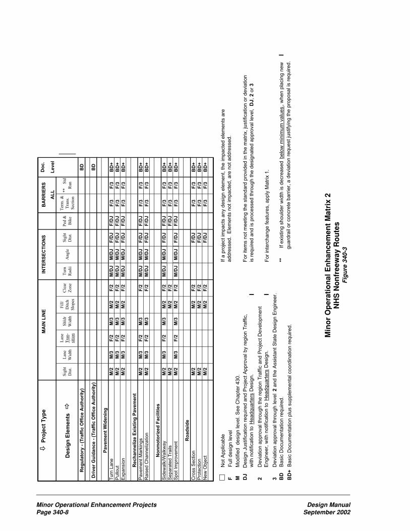
Minor Operational Enhancement Projects Design ManualPage 340-8 September 2002
P
roje
ct
Typ
eM
AIN
LIN
EIN
TE
RS
EC
TIO
NS
BA
RR
IER
SD
oc
.
AL
LL
ev
el
Desig
n E
lem
en
ts
S
igh
t
Dis
t.
Lan
e
Wid
th
Lan
e
Tra
n-
siti
on
Shld
r
Wid
th
Fil
l/
Dit
ch
Slo
pes
Cle
ar
Zone
Turn
Rad
iiA
ngle
Sig
ht
Dis
t.
Ped
&
Bik
e
Ter
m. &
Tra
ns.
Sec
tion
** S
td
Run
Re
gu
lato
ry -
(T
raff
ic O
ffic
e A
uth
ori
ty)
BD
Dri
ve
r G
uid
an
ce
- (
Tra
ffic
Off
ice
Au
tho
rity
)
BD
Pa
ve
me
nt
Wid
en
ing
Tu
rn L
an
eM
/2M
/3F
/2M
/3M
/2F
/2M
/DJ
M/D
JF
/DJ
F/D
JF
/3F
/3B
D+
Pu
llou
tM
/2M
/3F
/2M
/3M
/2F
/2M
/DJ
M/D
JF
/DJ
F/D
JF
/3F
/3B
D+
Exp
an
sio
nM
/2M
/3F
/2M
/3M
/2F
/2M
/DJ
M/D
JF
/DJ
F/D
JF
/3F
/3B
D+
Re
ch
an
ne
lize
Ex
isti
ng
Pa
ve
me
nt
Pa
ve
me
nt
Ma
rkin
gs
M/2
M/3
F/2
M/3
F/2
M/D
JM
/DJ
F/D
JF
/DJ
F/3
F/3
BD
+
Ra
ise
d C
ha
nn
eliz
atio
nM
/2M
/3F
/2M
/3F
/2M
/DJ
M/D
JF
/DJ
F/D
JF
/3F
/3B
D+
No
nm
oto
rize
d F
ac
ilit
ies
Sid
ew
alk
/Wa
lkw
ay
M/2
M/3
F/2
M/3
M/2
F/2
M/D
JM
/DJ
F/D
JF
/DJ
F/3
F/3
BD
+
Se
pa
rate
d T
rails
M/2
M/2
F/2
F/D
JF
/3F
/3B
D+
Sp
ot
Imp
rove
me
nt
M/2
M/3
F/2
M/3
M/2
F/2
M/D
JM
/DJ
F/D
JF
/DJ
F/3
F/3
BD
+
Ro
ad
sid
e
Cro
ss S
ectio
nM
/2M
/2F
/2F
/DJ
F/3
F/3
BD
+
Pro
tectio
nM
/2M
/2F
/2F
/DJ
F/3
F/3
BD
+
Ne
w O
bje
ct
M/2
M/2
F/2
F/D
JF
/3F
/3B
D+
No
t A
pp
lica
ble
If a
pro
ject
imp
acts
an
y d
esig
n e
lem
en
t, t
he
im
pa
cte
d e
lem
en
ts a
re
F
Fu
ll d
esig
n le
ve
l a
dd
resse
d.
Ele
me
nts
no
t im
pa
cte
d,
are
no
t a
dd
resse
d.
M
Mo
difie
d
de
sig
n le
ve
l. S
ee
Ch
ap
ter
43
0.
DJ
De
sig
n J
ustifica
tio
n r
eq
uire
d a
nd
Pro
ject
Ap
pro
va
l b
y r
eg
ion
Tra
ffic
,F
or
ite
ms n
ot
me
etin
g t
he
sta
nd
ard
pro
vid
ed
in
th
e m
atr
ix,
justifica
tio
n o
r d
evia
tio
n
with
no
tifica
tio
n t
o H
ea
dq
ua
rte
rs D
esig
n.
lis
re
qu
ire
d a
nd
is p
roce
sse
d t
hro
ug
h t
he
de
sig
na
ted
ap
pro
va
l le
ve
l, D
J,
2 o
r 3
2
De
via
tio
n a
pp
rova
l th
rou
gh
th
e r
eg
ion
Tra
ffic
an
d P
roje
ct
De
ve
lop
me
nt
En
gin
ee
r, w
ith
no
tifica
tio
n t
o H
ea
dq
ua
rte
rs D
esig
n.
lF
or
inte
rch
an
ge
fe
atu
res,
ap
ply
Ma
trix
1.
3
De
via
tio
n a
pp
rova
l th
rou
gh
le
ve
l 2
an
d t
he
Assis
tan
t S
tate
De
sig
n E
ng
ine
er.
BD
Ba
sic
Do
cu
me
nta
tio
n r
eq
uire
d.
**
If
exis
tin
g s
ho
uld
er
wid
th is d
ecre
ase
d b
elo
w m
inim
um
va
lue
s,
wh
en
pla
cin
g n
ew
l
BD
+
Ba
sic
Do
cu
me
nta
tio
n p
lus s
up
ple
me
nta
l co
ord
ina
tio
n r
eq
uire
d.
gu
ard
rail
or
co
ncre
te b
arr
ier,
a d
evia
tio
n r
eq
ue
st
justify
ing
th
e p
rop
osa
l is
re
qu
ire
d.
Min
or
Op
erat
ion
al E
nh
ance
men
t M
atri
x 2
NH
S N
on
free
way
Ro
ute
sF
igu
re 3
40-3

Design Manual Minor Operational Enhancement ProjectsSeptember 2002 Page 340-9
P
roje
ct
Typ
eM
AIN
LIN
EIN
TE
RS
EC
TIO
NS
BA
RR
IER
SD
oc.
AL
LL
evel
Desig
n E
lem
en
ts
Sig
ht
Dis
t.
Lan
e
Wid
th
Lan
e
Tra
n-
siti
on
Shld
r
Wid
th
Fil
l/
Dit
ch
Slo
pes
Cle
ar
Zone
Turn
Rad
iiA
ngle
Sig
ht
Dis
t.
Ped
&
Bik
e
Ter
m. &
Tra
ns.
Sec
tion
** S
td
Run
Reg
ula
tory
- (
Tra
ffic
Off
ice A
uth
ori
ty)
BD
Dri
ver
Gu
idan
ce -
(T
raff
ic O
ffic
e A
uth
ori
ty)
B
D
Pavem
en
t W
iden
ing
Turn
Lane
M/D
JM
/2F
/DJ
M/2
M/D
JF
/DJ
M/D
JM
/DJ
F/D
JF
/DJ
F/2
F/2
BD
+P
ullo
ut
M/D
JM
/2F
/DJ
M/2
M/D
JF
/DJ
M/D
JM
/DJ
F/D
JF
/DJ
F/2
F/2
BD
+E
xpansio
nM
/DJ
M/2
F/D
JM
/2M
/DJ
F/D
JM
/DJ
M/D
JF
/DJ
F/D
JF
/2F
/2B
D+
Rech
an
nelize E
xis
tin
g P
avem
en
t
Pavem
ent M
ark
ings
M/D
JM
/2F
/DJ
M/2
F/D
JM
/DJ
M/D
JF
/DJ
F/D
JF
/2F
/2B
D+
Rais
ed C
hanneliz
ation
M/D
JM
/2F
/DJ
M/2
F/D
JM
/DJ
M/D
JF
/DJ
F/D
JF
/2F
/2B
D+
No
nm
oto
rized
Facilit
ies
Sid
ew
alk
/Walk
wa
yM
/DJ
M/2
F/D
JM
/2M
/DJ
F/D
JM
/DJ
M/D
JF
/DJ
F/D
JF
/2F
/2B
D+
Separa
ted T
rails
M/D
JM
/DJ
F/D
JF
/DJ
F/2
F/2
BD
+S
pot Im
pro
vem
en
tM
/DJ
M/2
F/D
JM
/2M
/DJ
F/D
JM
/DJ
M/D
JF
/DJ
F/D
JF
/2F
/2B
D+
Ro
ad
sid
e
Cro
ss S
ection
M/D
JM
/DJ
F/D
JF
/DJ
F/2
F/2
BD
+P
rote
ction
M/D
JM
/DJ
F/D
JF
/DJ
F/2
F/2
BD
+N
ew
Ob
ject
M/D
JM
/DJ
F/D
JF
/DJ
F/2
F/2
BD
+
N
ot A
pplic
able
If a
pro
ject im
pacts
any d
esig
n e
lem
ent, the im
pacte
d e
lem
ents
are
F F
ull
desig
n level
addre
ssed. E
lem
ents
not im
pacte
d, are
not addre
ssed.
M M
odifie
d desig
n level. S
ee C
hapte
r 430.
DJ D
esig
n J
ustification r
equired a
nd P
roje
ct A
ppro
val by r
egio
n T
raffic
,F
or
item
s n
ot m
eeting the s
tandard
pro
vid
ed in the m
atr
ix, ju
stification o
r devia
tion
w
ith n
otification to H
eadquart
ers
Desig
n.
lis
required a
nd is p
rocessed thro
ugh the d
esig
nate
d a
ppro
val le
vel, D
J, 2 o
r 3
2 D
evia
tion a
ppro
val th
rough the r
egio
n T
raffic
and P
roje
ct D
evelo
pm
ent
E
ngin
eer,
with n
otification to H
eadquart
ers
Desig
n.
lF
or
inte
rchange featu
res, apply
Matr
ix 1
.
3 D
evia
tion a
ppro
val th
rough level 2
and the A
ssis
tant S
tate
Desig
n E
ngin
eer.
BD
B
asic
Docum
enta
tion r
equired.
** If exis
ting s
hould
er
wid
th is d
ecre
ased b
elo
w m
inim
um
valu
es,
when p
lacin
g n
ew
l
BD
+ B
asic
Docum
enta
tion p
lus s
upple
menta
l coord
ination r
equired.
g
uard
rail
or
concre
te b
arr
ier,
a d
evia
tion r
equest ju
stify
ing the p
roposal is
required.
Min
or
Op
erat
ion
al E
nh
ance
men
t M
atri
x 3
No
n-N
HS
Ro
ute
sF
igu
re 3
40-4

Minor Operational Enhancement Projects Design ManualPage 340-10 September 2002
DatePlaceholder
TO: Region Traffic Engineer
THRU:
FROM:
SUBJECT:
Design Approved By:
Region Traffic Engineer
Date
General Information
SR is a (NHS or Non-NHS) route, and classified as a (Urban or Rural) (Interstate,
Principle Arterial, Minor Arterial, or Collector) in County. The posted speed limit
is mph. The ADT is, with percent trucks. The project is within a (full,
partial, or modified limited access control, or Class 1 - 5 managed access controlled) area.
Project Initiation
How did the project get started? Accident history, constituent call, or letter?
Existing Geometrics
What is out there today? Lane, shoulder, sidewalk widths? Turn pockets, etc.?
Project Description
How did you come to the design decision being proposed? What does it resolve for the
situation at hand? What options have you looked at? Why were other options not selected?
Proposed Geometrics
What will be out there when you are through? Lane, shoulder, sidewalk widths? Turn
pockets, etc.?
Q Project Design Summary/Approval TemplateFigure 340-5a

Design Manual Minor Operational Enhancement ProjectsSeptember 2002 Page 340-11
Resurfacing
If pavement is involved what does the resurfacing report say to use?
Pavement Marking/Traffic Control Devices
What happens with the pavement markings? Signing? Illumination? Signals? Etc.?
Environmental Approval
Did you check with the Environmental Affairs Office? Are there any issues or permits that
need to be addressed? Hydraulics?
Deviations
Are there any deviations? Describe briefly what features are deviated and the date
of approval.
Permits
Are there any permits or easements needed? Construction permits? Noise variances?
Utility relocations? Detours? Others?
Project Cost and Schedule
How much do you anticipate spending? When is the project scheduled for advertisement?
When do you anticipate the project will be completed?
Sole Source Justification
Some traffic items are sole source and require justification. Have you completed the process?
Work Zone Traffic Control
What happens to traffic, pedestrians, and bicyclists during construction? Is a lane taken or
reduced in width? Night work? Shoulder work? Duration? Does Washington State Patrol
(WSP) need to be involved?
Local Agency Coordination
Do we need to coordinate with, or notify the city or county? WSP?
We are requesting approval for the Subject project. This project was designed in accordance
with Q Program guidelines for Minor Operational Enhancements, Matrix note
matrix title and project type line.
Typist’s Initials Placeholder
Attachments: Channelization Plan?
Permits?
Deviations?
cc: Headquarters Design 47329
Q Project Design Summary/Approval TemplateFigure 340-5b


Design Manual Impact Attenuator SystemsSeptember 2002 Page 720-1
720 Impact Attenuator Systems720.01 Impact Attenuator Systems720.02 Design Criteria720.03 Selection720.04 Documentation
720.01 Impact Attenuator SystemsImpact attenuator systems are protective systemsthat prevent an errant vehicle from impactinga hazard by either gradually decelerating thevehicle to a stop when hit head-on or byredirecting it away from the hazard when struckon the side. These barriers are used for rigidobjects or hazardous conditions that cannot beremoved, relocated, or made breakaway.
Approved systems are shown on Figures 720-2athrough 4b and on the Design Office web page at:
http://www.wsdot.wa.gov/EESC/Design/Policy/RoadsideSafety/Chapter720/Chapter720B.htm
(1) Permanent InstallationsA description of each permanent installationsystem’s purpose, parts, and function as well asrequirements for; transition, foundation, and slopeare provided as follows and in Figure 720-5:
(a) Crash Cushion Attenuating Terminal(CAT)
1. Purpose: The CAT is an end treatmentfor W-beam guardrail. It can also be used forconcrete barrier if a transition is provided.
2. Description: The system consists ofslotted W-beam guardrail mountedon both sides of breakaway timber posts.Steel sleeves with soil plates hold the timberposts in place. See Figure 720-2a.
3. Function: When hit head-on, the slottedguardrail is forced over a pin that shearsthe steel between the slots. This shearingdissipates the energy of the impact.
4. Foundation: Concrete footings orfoundations are not required.
5. Slope: 10H:1V or flatter slope betweenthe edge of the traveled way and the near faceof the unit.
6. Manufacturer/Supplier: TrinityIndustries, Inc.
(b) Brakemaster
1. Purpose: The Brakemaster system is anend treatment for W-beam guardrail. It canalso be used for concrete barrier if a transitionis provided.
2. Description: The system contains anembedded anchor assembly, W-beam fenderpanels, transition strap, and diaphragm. SeeFigure 720-2a.
3. Function: The system uses a brakeand cable device for head-on impacts andfor redirection. The cable is embedded ina concrete anchor at the end of the system.
4. Foundation: A concrete foundationis not required for this system but a pavedsurface is recommended.
5. Slope: 10H:1V or flatter slope betweenthe edge of the traveled way and the near faceof the unit.
6. Manufacturer/Supplier: EnergyAbsorption Systems
(c) QuadTrend 350
1. Purpose: The QuadTrend 350 is anend treatment for 32 in high concrete barriers.The system’s short length allows it to be usedat the ends of bridges where the installationof a beam guardrail transition and terminal isnot feasible.
2. Description: This system consistsof telescoping quadruple corrugated fenderpanels mounted on steel breakaway posts.See Figure 720-2a.

Impact Attenuator Systems Design ManualPage 720-2 September 2002
3. Function: Sand-filled boxes attachedto the posts dissipate a portion of the energyof an impact. An anchored cable installedbehind the fender panels directs the vehicleaway from the barrier end.
4. Foundation: The system is installedon a concrete foundation to support the steelposts.
5. Slope: A 6H:1V or flatter slope isrequired behind the barrier to allowfor vehicle recovery.
6. Manufacturer/Supplier: EnergyAbsorption Systems
(d) TAU-II1. Purpose: The TAU-II crash cushionsystem is an end treatment for concretebarrier and beam guardrail and is also usedfor narrow fixed objects.
2. Description: The system is made upof independent collapsible bays containingenergy absorbing cartridges that are guidedand supported during a head-on hit by highstrength galvanized steel cables and thriebeam rail panels. Each bay is composed ofoverlapping thrie beam panels on the sidesand structural support diaphragms on theends. Structural support diaphragms areattached to two cables running longitudinallythrough the system and attached tofoundations at each end of the system. SeeFigure 720-2c.
3. Function: Overlapping panels,structural support diaphragms, cablesupports, cables, and foundation anchorsallow the system to resist angled impactsand mitigate head-on impacts.
4. Foundation: The system is installedon a concrete foundation.
5. Slope: 10H:1V or flatter slope betweenthe edge of the traveled way and the near faceof the unit.
6. Manufacturer/Supplier: BarrierSystems, Inc.
(e) QuadGuard, Wide QuadGuard
1. Purpose: The QuadGuard is an endtreatment for concrete barrier and beamguardrail and is also used to mitigate fixedobjects up to 7.5 ft wide.
2. Description: The system consists ofa series of Hex-Foam cartridges surroundedby a framework of steel diaphragms andquadruple corrugated fender panels. SeeFigure 720-2b.
3. Function: The internal shearing ofthe cartridges and the crushing of the energyabsorption material absorb impact energyfrom end-on hits. The fender panels redirectvehicles impacting the attenuator on the side.
4. Foundation: The system is installedon a concrete foundation.
5. Slope: If the site has excessive gradeor cross slope, additional site preparation ormodification to the units in accordance withthe manufacturer’s literature is required.Excessive is defined as steeper than 8% forthe QuadGuard.
6. Manufacturer/Supplier: EnergyAbsorption Systems
(f) QuadGuard Elite
1. Purpose: The QuadGuard Elite is anend treatment for concrete barrier and beamguardrail and is also used forfixed objects up to 7.5 ft wide.
2. Description: The system consists oftelescoping quadruple corrugated fenderpanels mounted on both sides of a series ofpolyethylene cylinders. See Figure 720-2b.
3. Function: The cylinders arecompressed during a head-on impactand will return to their original shape whenthe system is reset. The advantage of thissystem is that it can withstand numerousimpacts without requiring extensive repair.
4. Foundation: The system is installed ona concrete foundation.

Design Manual Impact Attenuator SystemsSeptember 2002 Page 720-3
5. Slope: If the site has excessive gradeor cross slope, additional site preparation ormodification to the units in accordance withthe manufacturer’s literature is required.Excessive is defined as steeper than 8% forthe QuadGuard Elite.
6. Manufacturer/Supplier: EnergyAbsorption Systems
(g) Reusable Energy Absorbing CrashTerminal (REACT 350), Wide REACT 350
1. Purpose: The REACT 350 is an endtreatment for concrete barriers and is alsoused for fixed objects up to 9 ft wide.
2. Description: The system consists ofpolyethylene cylinders with varyingwall thickness, redirecting cables, a steelframe base, and a backup structure. SeeFigure 720-2d.
3. Function: The redirecting cables areanchored in the concrete foundation atthe front of the system and in the backupstructure at the rear of the system. When hithead-on, the cylinders compress and absorbthe impact energy, but the system returnsto approximately 80% of its original lengthimmediately. For side impacts, the cablesrestrain the system enough to preventpenetration and redirect the vehicle. It isanticipated that this system will require veryfew replacement parts or extensive repair.
4. Foundation: The system is installedon a concrete foundation.
5. Slope: If the site has excessive gradeor cross slope, additional site preparation ormodification to the units in accordance withthe manufacturer’s literature is required.Excessive is defined as steeper than 8% forthe REACT 350.
6. Manufacturer/Supplier: EnergyAbsorption Systems
(h) Inertial Barrier
Inertial barrier configurations are shownin the Standard Plans. If a situation is encounteredwhere configurations in the Standard Plans arenot appropriate, contact the Headquarters DesignOffice for further information.
1. Purpose: Inertial barrier is an endtreatment for concrete barrier and to mitigatefixed objects. This system does not provideredirection from a side impact.
2. Description: This system consists ofan array of plastic containers filled withvarying weights of sand. See Figure720-2d.
3. Function: The inertial barriers slowan impacting vehicle by the transfer of themomentum of the vehicle to the mass of thebarrier. This system is not suitable wherespace is limited to less than the widths shownin the Standard Plans. Whenever possible,align inertial barriers so that an errant vehicledeviating from the roadway by 10 degreeswould be on a parallel path with theattenuator alignment (See the StandardPlans). In addition, inertial barriers donot provide any redirection and are notappropriate where high angle impacts arelikely.
4. Foundation: A paved surface is notrequired.
5. Slope: If the site has excessive gradeor cross slope, additional site preparation ormodification to the units in accordance withthe manufacturer’s literature is required.Excessive is defined as steeper than 5% forinertial barriers.
(2) Work Zone (Temporary)InstallationA description of each work zone (or othertemporary) system’s purpose, parts andfunctionality as well as requirements for;transition, foundation, and slope are providedas follows and in Figure 720-5:
(a) ABSORB 350
1. Purpose: The ABSORB 350 isan end treatment limited to temporaryinstallations for both concrete barrier andthe Quickchange Moveable Barrier (QMB).
2. Description: The system contains waterfilled Energy Absorbing Elements. Eachelement is 24 inches wide, 32 inches high,and 39 ½ inches long. See Figure 720-3.

Impact Attenuator Systems Design ManualPage 720-4 September 2002
3. Function: The low speed (below 45mph) system uses 5 Energy AbsorbingElements and the high-speed (45 mph andabove) system uses 8. The energy of animpact is dissipated as the elements arecrushed.
4. Foundation: The system does notrequire a paved foundation.
5. Slope: 10H:1V or flatter slope betweenthe edge of the traveled way and the near faceof the unit.
6. Manufacturer/Supplier: BarrierSystems, Inc.
(b) Advanced Dynamic Impact ExtensionModule 350 (ADIEM 350)
1. Purpose: The ADIEM 350 is an endtreatment for concrete barrier. At this time, itis limited to temporary installations. Existingpermanent installations are experimentaland are being used to evaluate long-termdurability. Existing permanent unitsmay be reset.
2. Description: The system is 30 ftlong and consists of 10 lightweight concretemodules on an inclined base. See Figure720-3.
3. Functionality: An inclined baseprovides a track for placement of the modulesand provides redirection for side impacts forroughly half the length. The energy of animpact is dissipated as the concrete modulesare crushed.
4. Foundation: The system does notrequire a paved foundation.
5. Slope: If the site has excessive gradeor cross slope, additional site preparation ormodification to the units in accordance withthe manufacturer’s literature is required.Excessive is defined as steeper than 8% forthe ADIEM 350.
6. Manufacturer/Supplier: TrinityIndustries, Inc.
(c) QuadGuard cz
This system is like the permanent QuadGuardlisted for permanent systems above except that itcan be installed on a 6 in minimum depth asphaltconcrete surface that has a 6 in minimum depthcompacted base. See Figure 720-2b.
(d) Reusable Energy Absorbing CrashTerminal (REACT 350)
This is the same system listed for permanentsystems above except that it can be installed on a4 in minimum depth asphalt concrete surface thathas a 6 in minimum depth compacted base. SeeFigure 720-2d.
(e) Non-Redirecting Energy AbsorbingTerminal (N-E-A-T)
1. Purpose: The N-E-A-T system is anend treatment for temporary concrete barrierwhere vehicle speeds are 45 mph or less.
2. Description: The N-E-A-T System’scartridge weighs about 300 pounds andmeasures 9.7 ft in length. The system consistsof aluminum cells encased in an aluminumshell with steel backup, attachment hardware,and transition panels. It can be attached to theends of New Jersey shaped portable concretebarrier and the moveable QuickChangeBarrier. See Figure 720-3.
3. Functionality: The energy of an impactis dissipated as the aluminum cells arecrushed.
4. Foundation: The system does notrequire a paved foundation.
5. Slope: 10H:1V or flatter slope betweenthe edge of the traveled way and the near faceof the unit.
6. Manufacturer/Supplier: EnergyAbsorption Systems
(f) Trinity Attenuating Crash Cushion(TRACC)
1. Purpose: The TRACC is an end treat-ment for concrete barriers. It is limited to usein construction or other work zones on atemporary basis.

Design Manual Impact Attenuator SystemsSeptember 2002 Page 720-5
2. Description: The 21 foot longTRACC includes four major components:a pair of guidance tracks, an impact sled,intermediate steel frames, and 10 gaugeW-beam fender panels. See Figure 720-3.
3. Functionality: The sled (impact face) ispositioned over the upstream end of theguidance tracks and contains a hardened steelblade that cuts the metal plates on the sides ofthe guidance tracks as it is forced backwardswhen hit head-on.
4. Foundation: The system requires aconcrete foundation.
5. Slope: 10H:1V or flatter slope betweenthe edge of the traveled way and the near faceof the unit.
6. Manufacturer/Supplier: TrinityIndustries, Inc.
(g) Inertial Barrier
This is the same system listed for permanentsystems above. It is not suitable where spaceis limited to less than the widths shown in theStandard Plans. See Figure 720-2d.
(h) Truck Mounted Attenuator (TMA)
TMAs are portable systems mounted on trucks.They are intended for use in work zones and fortemporary hazards.
(3) Older SystemsThe following systems are in use on WashingtonState highways and may be left in place or reset.New installations of these systems requireapproval from the Headquarters (HQ) DesignOffice.
(a) Sentre
The Sentre is a guardrail end treatment. Its overalllength of 17 ft allowed it to be used where spacewas not available for a guardrail transition andterminal. The system is very similar to theQuadTrend-350 in both appearance and functionexcept that it uses thrie beam fender panelsinstead of the quadruple corrugated panels.This system requires a transition when usedto terminate rigid barriers. See Figure 720-4a.
(b) TREND
The TREND is an end treatment with a built-intransition and was used at the end of rigid barriersincluding bridge rails. The system is similar to theQuadTrend-350 except that it uses thrie beamfender panels. See Figure 720-4a.
(c) G-R-E-A-T (Guard Rail EnergyAbsorption Terminal)
This system was primarily used as an endtreatment for concrete barrier. It is similar tothe QuadGuard except that it uses thrie beamfender panels. See Figure 720-4a.
(d) Low Maintenance Attenuator System(LMA)
The LMA is an end treatment for concrete barrierand beam guardrail and was used for fixedobjects up to 3 ft wide. The system is similar tothe QuadGuard Elite except that it uses thriebeam fender panels and rubber cylinders. SeeFigure 720-4b.
(e) Hex-Foam Sandwich
The Hex-Foam Sandwich system is an endtreatment for beam guardrail and concrete barrierand was also used for fixed objects 3 ft or morein width. This system consists of a number ofHex-Foam cartridges containing an energyabsorption material separated by a series ofdiaphragms and restrained by anchor cables. Itis installed on a concrete slab. Impact energy isabsorbed by the internal shearing of the cartridgesand crushing of the energy absorption material.The lapped panels on the perimeter serve toredirect vehicles for side impacts. If the site hasgrade or cross slope in excess of 5%, additionalsite preparation or modification to the units inaccordance with the manufacturer’s literature isrequired. See Figure 720-4b.
720.02 Design CriteriaThe following design criteria applies to all newor reset permanent and temporary impactattenuators. The design criteria also applies toexisting systems to be left in place when theBarrier Terminals and Transition Sectionscolumns on a design matrix applies to the project.(See Chapter 325.)

Impact Attenuator Systems Design ManualPage 720-6 September 2002
If it is anticipated that a large volume of trafficwill be traveling at speeds greater than the postedspeed limit, then the next larger unit may bespecified.
See Figure 720-5 for a summary of space andinitial cost information related to the impactattenuator systems.
When considering maintenance costs, anticipatethe average annual impact rate. If few impactsare anticipated, lower cost devices such asinertial barriers might meet the need. Inertialbarriers have the lowest initial cost and initialsite preparation. However, maintenance will becostly and necessary after every impact. Laborand equipment are necessary to clean up thedebris and install new containers (barrels). Also,inertial barriers must not be used where flyingdebris might be a danger to pedestrians.
The REACT 350 and the QuadGuard Elite havea higher initial cost, requiring substantial sitepreparation, including a backup or anchor wallin some cases and cable anchorage at the frontof the installation. However, repair costs arecomparatively low, with labor being the mainexpense. Maintenance might not be requiredafter minor side impacts with these systems.
For new installations where at least one impactis anticipated per year, limit the selection ofimpact attenuators to the low maintenancedevices (QuadGuard Elite and REACT 350).Consider upgrading existing ADIEM,G-R-E-A-T, and Hex-Foam impact attenuatorswith these low maintenance devices when therepair history shows one to two impacts per yearover a three to five year period.
In selecting a system, one consideration that mustnot be overlooked is how dangerous it will be forthe workers making repairs. In areas with a highexposure to danger, a system that can be repairedquickly is most desirable. Some systems requirenearly total replacement or replacement of criticalcomponents (such as cartridges or brakingmechanisms) after a head-on impact, while othersonly require resetting.
Impact attenuators must be placed so that they donot present a hazard to opposing traffic. Formedian and reversible lane locations, the backupstructure or attenuator-to-object connection mustbe designed to prevent opposing traffic frombeing snagged. It is desirable that all existingcurbing be removed and the surface smoothedwith asphalt or cement concrete pavement beforean impact attenuator is installed. However, curbs4 in or less in height, may be retained dependingon the practicality of their removal.
In general, attenuators are aligned parallel to theroadway except the inertial barriers.
720.03 SelectionWhen selecting an impact attenuator system,consider the following:
• Posted speed
• Available space (length and width)
• Maintenance costs
• Initial cost
• Duration (permanent or temporary use)
The posted speed is a consideration for theQuadGuard, REACT 350 (narrow model only),TAU II and the inertial barrier systems. UseFigure 720-1 to select permanent system sizesrequired for the various posted speeds.
Posted Quad TAU-II REACT InertialSpeed Guard (Bays) 350 Barrier(mph) (Bays) (Cylinders) (Type)
40 3 4 4 1or less
45 4 8 6 2
50 5 8 6 3
55 6 8 9 4
60 6 8 9 5
65 8 8 9 6
70 9 8 11 6
Impact Attenuator SizesFigure 720-1

Design Manual Impact Attenuator SystemsSeptember 2002 Page 720-7
When specifying the system or systems thatcan be used at a specific location, the list shownin Figure 720-5 is to be used as a starting point.As the considerations discussed previously areanalyzed, inappropriate systems may be identifiedand eliminated from further consideration.Systems that are not eliminated may beappropriate for the project. When the siteconditions vary, it might be necessary to havemore than one list of acceptable systems withina contract. Systems are not to be eliminatedwithout documented reasons. Also, wording suchas or equivalent is not to be used when specifyingthese systems. If only one system is found to beappropriate, then approval from the AssistantState Design Engineer of a public interestfinding for the use of a sole source proprietaryitem is required.
When a transition to connect with a concretebarrier (see Figure 720-5) is required, thetransition type and connection must be specifiedand are included in the cost of the impactattenuator. See Chapter 710 for informationon the transitions and connections to be used.
Contractors can be given more flexibility in theselection of work zone (temporary) systems, sincelong-term maintenance and repair are nota consideration.
720.04 DocumentationThe following documents are to be preserved inthe project’s design documentation file. SeeChapter 330.
Approvals for use of older systems.
Documentation of reasons for eliminatingattenuator options.
Approvals of public interest findingsregarding sole source proprietary systems.

Impact Attenuator Systems Design ManualPage 720-8 September 2002
Impact Attenuator Systems — Permanent InstallationsFigure 720-2a
CAT
Brakemaster
QuadTrend 350

Design Manual Impact Attenuator SystemsSeptember 2002 Page 720-9
QuadGuard
Wide QuadGuard
Wide QuadGuard Elite
Impact Attenuator Systems — Permanent InstallationsFigure 720-2b
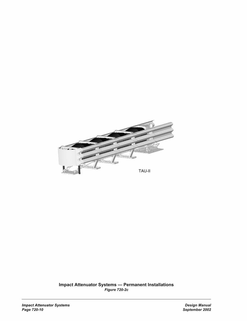
Impact Attenuator Systems Design ManualPage 720-10 September 2002
Impact Attenuator Systems — Permanent InstallationsFigure 720-2c
Wide Quad Guard impact attenuator
TAU-II
Wide Quad Guard impact attenuator

Design Manual Impact Attenuator SystemsSeptember 2002 Page 720-11
Impact Attenuator Systems — Permanent InstallationsFigure 720-2d
Inertial Barrier
Wide REACT 350
REACT 350
Wide Quad Guard impact attenuator

Impact Attenuator Systems Design ManualPage 720-12 September 2002
Impact Attenuator Systems — Work Zone InstallationsFigure 720-3
ADIEM 350
ABSORB 350
TRACC
N-E-A-T

Design Manual Impact Attenuator SystemsSeptember 2002 Page 720-13
Impact Attenuator Systems — Older SystemsFigure 720-4a
Sentre
TREND
G-R-E-A-T

Impact Attenuator Systems Design ManualPage 720-14 September 2002
Impact Attenuator Systems — Older SystemsFigure 720-4b
L.M.A
Hex-Foam Sandwich
TREND impact attenuator

Design Manual Impact Attenuator SystemsSeptember 2002 Page 720-15
Impact Attenuator ComparisonFigure 720-5
1) A ($5,000 to $10,000); B ($10,000 to $15,000); C ($15,000 to $25,000); D ($25,000 to $40,000).These are rough initial cost estimates - verify actual costs through manufacturers/suppliers.Some products are priced very close to the margin between cost categories.
2) Generally for use with double-sided beam guardrail. Use as an end treatment for concrete barrierrequires a transition.
3) The N-E-A-T, inertial barriers, and ABSORB 350 may only be used beyond the required lengthof need.
4) See Figure 720-1 for sizes or configuration type.5) The length of the QuadGuard, REACT 350, TAU-II, ABSORB 350, and inertial barriers varies since
their designs are dependent upon speed. For a typical 60 mph design: the QuadGuard = 21 ft,the REACT 350 = 31 ft, the ABSORB 350 = 27 ft, the TAU II = 26 ft, and the inertial barrier = 30 ft.Costs indicated are for a typical 60 mph design. (except N-E-A-T)
6) Generally for use at the ends of bridges where installation of a beam guardrail transition andterminal is not feasible.
7) Generally for use with concrete barrier. Other uses may require a special transition design.8) Use limited to highways with posted speeds of 45 mph or less.9) The ABSORB 350 was primarily intended for the Quickchange Moveable Barrier (QMB) but may be
used with other temporary barrier if beyond the length of need.
Impact Attenuator Systems(All dimensions are in feet)
System (P) p
erm
anen
t,
(T) t
empo
rary
,
(B) b
oth
Wid
th
Leng
th
Tran
sitio
n to
Rig
id S
yste
m
Req
uire
dDis
tanc
e
Bey
ond
Leng
th
of N
eed
Initi
al C
ost
Cat
egor
y(1
)
CAT(2) P 2 31.25 Y 18.8 A
Brakemaster(2) P 2 31.5 Y 15.8 A
QuadTrend - 350(6) P 2 20.7 N 10.5 A
TAU-II P 2.9 14 -26(4) N 3 B
(5)
QuadGuard B2, 2.5, 3,
5.75, 7.512 - 30
(4) N 3.3 C(5)
QuadGuard Elite B2, 2.5, 3,
5.75, 7.5 35.5 N 3.3 D
REACT 350 B 3 15.25 - 36.25(4) N 4.3 C
(5)
Wide REACT 350 B 6-9 23.25 N 4.3 D(5)
Inertial Barriers B 7 17 - 30(4) N (3)
A(5)
ABSORB 350(9) T 2 17.7/27 Y 17.7/27(3) A(5)
ADIEM 350(7) T 2 30 N 14.1 B
QuadGuard cz T2, 2.5, 3,
5.75, 7.522 N 3.3 C
(5)
N-E-A-T(8) T 1.9 9.7 N (3)
C(5)
TRACC T 2.6 21 N 8 B


Design Manual Traffic InterchangesSeptember 2002 Page 940-1
940 Traffic Interchanges
A Policy on Geometric Design of Highways andStreets (Green Book), 2001, AASHTO
A Policy on Design Standards - Interstate System,1991, AASHTO
Highway Capacity Manual (Special Report 209),Transportation Research Board
Procedure for Analysis and Design of WeavingSections, A User’s Guide, October 1985,Jack E. Leisch.
940.03 Definitionsauxiliary lane The portion of the roadwayadjoining the traveled way for parking, speedchange, turning, storage for turning, weaving,truck climbing, passing, and other purposessupplementary to through traffic movement
basic number of lanes The minimum numberof general purpose lanes designated andmaintained over a significant length of highway.
collector distributor road (C-D road) A parallelroadway designed to remove weaving from themain line and to reduce the number of main lineentrances and exits.
decision sight distance The sight distancerequired for a driver to detect an unexpectedor difficult-to-perceive information source orhazard, interpret the information, recognize thehazard, select an appropriate maneuver, andcomplete it safely and efficiently.
frontage road An auxiliary road that is a localroad or street located on the side of a highway forservice to abutting properties and adjacent areas,and for control of access.
gore The area downstream from the intersectionof the shoulders of the main line and exit ramp.Although generally the area between a main lineand an exit ramp, the term may also be used torefer to the area between a main line and anentrance ramp.
intersection at grade The general area where astate highway or ramp terminal is met or crossedat a common grade or elevation by another statehighway, a county road, or a city street.
940.01 General940.02 References940.03 Definitions940.04 Interchange Design940.05 Ramps940.06 Interchange Connections940.07 Ramp Terminal Intersections at
Crossroads940.08 Interchanges on Two-Lane Highways940.09 Interchange Plans940.10 Documentation
940.01 GeneralThe primary purpose of an interchange is toeliminate conflicts caused by vehicle crossingsand to minimize conflicting left-turn movements.Interchanges are provided on all Interstatehighways, freeways, other routes on which fullaccess control is required, and at other locationswhere traffic cannot be controlled safely andefficiently by intersections at grade.
See the following chapters for additionalinformation:
Chapter Subject
640 Superelevation640 Turning Widths640 Ramp Sections910 Intersections1050 HOV Lanes1420 Access Control1425 Access Point Decision Report
940.02 ReferencesStandard Plans for Road, Bridge, and MunicipalConstruction (Standard Plans), M 21-01,WSDOT
Plans Preparation Manual, M 22-31, WSDOT
HOV Direct Access Design Guide, DraftM 22-98, WSDOT
Standard Specifications for Road, Bridge,and Municipal Construction (StandardSpecifications), M 41-10, WSDOT.

Traffic Interchanges Design ManualPage 940-2 September 2002
Interstate System A network of routes selectedby the state and the FHWA under terms of thefederal aid acts as being the most important to thedevelopment of a national transportation system.The Interstate System is part of the principalarterial system.
lane A strip of roadway used for a single lineof vehicles.
median The portion of a divided highwayseparating the traveled ways for traffic inopposite directions.
outer separation The area between the outsideedge of traveled way for through traffic and thenearest edge of traveled way of a frontage road.
painted nose The point where the main line andramp lanes separate.
physical nose The point, upstream of the gore,with a separation between the roadways of 16 to22 ft. See Figures 940-11a and 11b.
ramp A short roadway connecting a main laneof a freeway with another facility for vehicularuse such as a local road or another freeway.
ramp connection The pavement at the end ofa ramp, connecting it to a main lane of a freeway.
ramp meter A traffic signal at a freeway entranceramp that allows a measured or regulated amountof traffic to enter the freeway.
ramp terminal The end of a ramp at a localroad.
roadway The portion of a highway, includingshoulders, for vehicular use. A divided highwayhas two or more roadways.
sight distance The length of highway visibleto the driver.
shoulder The portion of the roadwaycontiguous with the traveled way, primarily foraccommodation of stopped vehicles, emergencyuse, lateral support of the traveled way, and(where permitted) use by bicyclists andpedestrians.
stopping sight distance The sight distancerequired to detect a hazard and safely stop avehicle traveling at design speed.
traffic interchange A system ofinterconnecting roadways, in conjunction withone or more grade separations, providing forthe exchange of traffic between two or moreintersecting highways or roadways.
traveled way The portion of the roadwayintended for the movement of vehicles, exclusiveof shoulders and lanes for parking, turning, andstorage for turning.
940.04 Interchange Design(1) GeneralAll freeway exits and entrances, except HOVdirect access connections, are to connect on theright of through traffic. Deviations from thisrequirement will be considered only for specialconditions.
HOV direct access connections may beconstructed on the left of through traffic whenthey are designed in accordance with the HOVDirect Access Design Guide.
Provide complete ramp facilities for all directionsof travel wherever possible. However, giveprimary consideration to the basic trafficmovement function that the interchange isto fulfill.
Few complications will be encountered in thedesign and location of rural interchanges thatsimply provide a means of exchanging trafficbetween a limited access freeway and a localcrossroad. The economic and operational effectsof locating traffic interchanges along a freewaythrough a community requires more carefulconsideration, particularly with respect to localaccess, to provide the best local service possiblewithout reducing the capacity of the major routeor routes.
Where freeway to freeway interchanges areinvolved, do not provide ramps for local accessunless they can be added conveniently andwithout detriment to safety or reduction of rampand through-roadway capacity. When exchangeof traffic between freeways is the basic functionand local access is prohibited by access controlrestrictions or traffic volume, it may be necessaryto provide separate interchanges for local service.

Design Manual Traffic InterchangesSeptember 2002 Page 940-3
(2) Interchange PatternsBasic interchange patterns have been establishedthat can be used under certain general conditionsand modified or combined to apply to manymore. Alternatives must be considered in thedesign of a specific facility, but the conditionsin the area and on the highway involved mustgovern and rigid patterns must not beindiscriminately imposed.
Selection of the final design must be basedon a study of projected traffic volumes, siteconditions, geometric controls, criteria forintersecting legs and turning roadways, driverexpectancy, consistent ramp patterns, continuity,and cost.
The patterns most frequently used for interchangedesign are those commonly described asdirectional, semidirectional, cloverleaf, partialcloverleaf, diamond, and single point (urban)interchange. (See Figure 940-4.)
(a) Directional A directional interchangeis the most effective design for connection ofintersecting freeways. The directional patternhas the advantage of reduced travel distance,increased speed of operation, and higher capacity.These designs eliminate weaving and have afurther advantage over cloverleaf designs inavoiding the loss of sense of direction driversexperience in traveling a loop. This type ofinterchange is costly to construct, commonlyusing a four-level structure.
(b) Semidirectional A semidirectionalinterchange has ramps that loop around theintersection of the highways. This requiresmultiple single-level structures and more areathan the directional interchange.
(c) Cloverleaf The full cloverleaf interchangehas four loop ramps that eliminate all the left-turnconflicts. Outer ramps provide for the right turns.A full cloverleaf is the minimum type interchangethat will suffice for a freeway-to-freewayinterchange. Cloverleaf designs often incorporatea C-D road to minimize signing difficulties andto remove weaving conflicts from the mainroadway.
The principal advantage of this design is theelimination of all left-turn conflicts with onesingle-level structure. Because all movementsare merging movements, it is adaptable to anygrade line arrangement.
The cloverleaf has some major disadvantages.The left-turn movement has a circuitous routeon the loop ramp, the speeds are low on the loopramp, and there are weaving conflicts betweenthe loop ramps. The cloverleaf also requires alarge area. The weaving and the radius of theloop ramps are a capacity constraint on theleft-turn movements.
(d) Partial Cloverleaf (PARCLO) A partialcloverleaf has loop ramps in one, two, or threequadrants that are used to eliminate the majorleft-turn conflicts. These loops may also serveright turns for interchanges that have one or twoquadrants that must remain undeveloped. Outerramps are provided for the remaining turns.Design the grades to provide sight distancebetween vehicles approaching these ramps.
(e) Diamond A diamond interchange hasfour ramps that are essentially parallel to themajor arterial. Each ramp provides for one rightand one left-turn movement. Because left-turnsare made at grade across conflicting traffic on thecrossroad, intersection sight distance is a primaryconsideration.
The diamond design is the most generallyapplicable and serviceable interchangeconfiguration and usually requires less spacethan any other type. Consider this design firstwhen a semidirectional interchange is requiredunless another design is clearly dictated bytraffic, topography, or special conditions.
(f) Single Point (Urban) A single point urbaninterchange is a modified diamond with all of itsramp terminals on the crossroad combined intoone signalized at-grade intersection. This singleintersection accommodates all interchange andthrough movements.
A single point urban interchange can improve thetraffic operation on the crossroad with less rightof way than a typical diamond interchange;however, a larger structure is required.

Traffic Interchanges Design ManualPage 940-4 September 2002
(3) SpacingTo avoid excessive interruption of main linetraffic, consider each proposed facility inconjunction with adjacent interchanges,intersections, and other points of access alongthe route as a whole.
The minimum spacing between adjacentinterchanges is 1 mi in urban areas and 2 miin rural areas. In urban areas, spacing less than1 mi may be used with C-D roads or gradeseparated (braided) ramps. Generally, the averageinterchange spacing is not less than 2 mi inurban areas and not less than 4 mi in suburbanareas. Interchange spacing is measured alongthe freeway center line between the center linesof the crossroads.
The spacing between interchanges may alsobe dependent on the spacing between ramps.The minimum spacing between the noses ofadjacent ramps is given on Figure 940-5.
Consider either frontage roads or C-D roadswhen it is necessary to facilitate the operationof near-capacity volumes between closely spacedinterchanges or ramp terminals. C-D roads maybe required where cloverleaf loop ramps areinvolved or where a series of interchange rampsrequires overlapping of the speed change lanes.Base the distance between successive rampterminals on capacity requirements and checkthe intervening sections by weaving analysisto determine whether adequate capacity and sightdistance and effective signing can be ensuredwithout the use of auxiliary lanes or C-D roads.
(4) Route ContinuityRoute continuity refers to the providing ofa directional path along the length of a routedesignated by state route number. Provide thedriver of a through route a path on which lanechanges are minimized and other trafficoperations occur to the right.
In maintaining route continuity, interchangeconfiguration may not always favor the heavytraffic movement, but rather the through route.In this case, design the heavy traffic movementswith multilane ramps, flat curves, and reasonablydirect alignment.
(5) DrainageAvoid interchanges located in proximity tonatural drainage courses. These locations oftenresult in complex and unnecessarily costlyhydraulic structures.
The open areas within an interchange can be usedfor storm water detention facilities when thesefacilities are required.
(6) Uniformity of Exit PatternWhile interchanges are of necessity customdesigned to fit specific conditions, it is desirablethat the pattern of exits along a freeway havesome degree of uniformity. From the standpointof driver expectancy, it is desirable that eachinterchange have only one point of exit, locatedin advance of the crossroad.
940.05 Ramps(1) Ramp Design SpeedThe design speed for a ramp is based on thedesign speed for the freeway main line.
It is desirable for the ramp design speed at theconnection to the freeway be equal to the free-flow speed of the freeway. Meet or exceed theupper range values from Figure 940-1 for thedesign speed at the ramp connection to thefreeway. Transition the ramp design speed toprovide a smooth acceleration or decelerationbetween the speeds at the ends of the ramp.However, do not reduce the ramp design speedbelow the lower range speed of 25 mph. For loopramps, use a design speed as high as practical, butnot less than 25 mph.
These design speed guidelines do not apply to theramp in the area of the ramp terminal at-gradeintersection. In the area of the intersection, adesign speed of 15 mph for turning traffic or0 mph for a stop condition is adequate. Use theallowed skew at the ramp terminal at-gradeintersection to minimize ramp curvature.
For freeway-to-freeway ramps and C-D roads, thedesign speed at the connections to both freewaysis the upper range values from Figure 940-1;however, with justification, the midrange valuesfrom Figure 940-1 may be used for the remainderof the ramp. When the design speed for the twofreeways is different, use the higher design speed.

Design Manual Traffic InterchangesSeptember 2002 Page 940-5
Existing ramps meet design speed requirementsif acceleration or deceleration requirements aremet (figure 940-8 or 940-10) and superelevationmeets or will be corrected to meet therequirements in Chapter 640.
Main Line Design 50 55 60 65 70 80Speed mph
Upper Range 45 50 50 55 60 70
Midrange 35 40 45 45 50 60
Lower 25 25 25 25 25 25Range
Ramp Design SpeedFigure 940-1
(2) Sight DistanceDesign ramps in accordance with provisions inChapter 650 for stopping sight distances.
(3) GradeThe maximum grade for ramps for various designspeeds is given in Figure 940-2.
Ramp Design 45 andSpeed (mph) 25-30 35-40 above
Desirable Grade (%) 5 4 3
Maximum Grade (%) 7 6 5
On one-way ramps down grades may be 2%greater.
Maximum Ramp GradeFigure 940-2
(4) Cross SectionProvide the minimum ramp widths given inFigure 940-3. Ramp traveled ways may requireadditional width to these minimums as one-wayturning roadways. See Chapter 640 for additionalinformation and roadway sections.
Number of Lanes 1 2
Traveled Way(1) 15(2) 25(3)
Shoulders Right 8 8Left 2 4
Medians(4) 6 8
(1) See Chapter 640 for turning roadwaywidths. See Chapter 1050 for additionalwidth when an HOV lane is present.
(2) May be reduced to 12 ft on tangents.(3) Add 12 ft for each additional lane.(4) The minimum median width is not less
than that required for traffic controldevices and their respective clearances.
Ramp Widths (ft)Figure 940-3
Cross slope and superelevation requirements forramp traveled way and shoulders are as given inChapter 640 for roadways.
Whenever feasible, make the ramp cross slope atthe ramp beginning or ending station equal to thecross slope of the through lane pavement. Wherespace is limited and superelevation runoff is longor when parallel connections are used, thesuperelevation transition may be ended beyond(for on-ramps) or begun in advance of (foroff-ramps) the ramp beginning or ending station,provided that the algebraic difference in crossslope at the edge of the through lane and the crossslope of the ramp does not exceed 4%. In suchcases, ensure smooth transitions for the edge oftraveled way.
(5) Ramp Lane IncreasesWhen off-ramp traffic and left-turn movementvolumes at the ramp terminal at-gradeintersection cause congestion, it may bedesirable to add lanes to the ramp to reduce thequeue length caused by turning conflicts. Makeprovision for the addition of ramp lanes wheneverramp exit or entrance volumes, after the designyear, are expected to result in poor service. SeeChapter 620 for width transition design.
Ram
p D
esig
nS
pee
d (
mp
h)

Traffic Interchanges Design ManualPage 940-6 September 2002
(6) Ramp MetersRamp meters are used to allow a measured orregulated amount of traffic to enter the freeway.When operating in the “measured” mode, theyrelease traffic at a measured rate to keepdownstream demand below capacity and improvesystem travel times. In the “regulated” mode,they break up platoons of vehicles that occurnaturally or result from nearby traffic signals.Even when operating at near capacity, a freewaymain line can accommodate merging vehiclesone or two at a time, while groups of vehicleswill cause main line flow to break down.
The location of the ramp meter is a balancebetween the storage and accelerationrequirements. Locate the ramp meter to maximizethe available storage and so that the accelerationlane length, from a stop to the freeway main linedesign speed, is available from the stop bar tothe merging point. With justification, the averagemain line running speed during the hours ofmeter operation may be used for the highwaydesign speed to determine the minimumacceleration lane length from the ramp meter.See 940.06(4) for information on the designof on-connection acceleration lanes. See Chapter860 for additional information on the design oframp meters.
Driver compliance with the signal is requiredfor the ramp meter to have the desired results.Consider enforcement areas with ramp meters.
Consider HOV bypass lanes with ramp meters.See Chapter 1050 for design data for ramp meterbypass lanes.
940.06 Interchange ConnectionsProvide uniform geometric design and uniformsigning for exits and entrances, to the extentpossible, in the design of a continuous freeway.Do not design an exit ramp as an extension of amain line tangent at the beginning of a main linehorizontal curve.
Provide spacing between interchange connectionsas given by Figure 940-5.
Avoid on-connections on the inside of a main linecurve, particularly when the ramp approach angleis accentuated by the main line curve, the ramp
approach requires a reverse curve to connect tothe main line, or the elevation difference willcause the cross slope to be steep at the nose.
Keep the use of mountable curb at interchangeconnections to a minimum. Justification isrequired when it is used adjacent to trafficexpected to exceed 40 mph.
(1) Lane BalanceDesign interchanges to the following principlesof lane balance:
(a) At entrances, make the number of lanesbeyond the merging of two traffic streams notless than the sum of all the lanes on the mergingroadways less one. (See Figure 940-6a.)
(b) At exits, make the number of approachlanes equal the number of highway lanes beyondthe exit plus the number of exit lanes less one.(See Figure 940-6a.) Exceptions to this are at acloverleaf or at closely spaced interchanges witha continuous auxiliary lane between the entranceand exit. In these cases the auxiliary lane maybe dropped at a single-lane, one lane reduction,off-connection with the number of approachlanes being equal to the sum of the highwaylanes beyond the exit and the number of exitlanes. Closely spaced interchanges have adistance of less than 2,100 ft between the endof the acceleration lane and the beginning ofthe deceleration lane.
Maintain the basic number of lanes, as describedin Chapter 620, through interchanges. When atwo-lane exit or entrance is used, maintain lanebalance with an auxiliary lane. (See Figure940-6b.) The only exception to this is whenthe basic number of lanes is changed at aninterchange.
(2) Main Line Lane ReductionThe reduction of a basic lane or an auxiliary lanemay be made at a two-lane exit or may be madebetween interchanges. When a two-lane exit isused, provide a recovery area with a normalacceleration taper. When a lane is droppedbetween interchanges, drop it 1,500 to 3,000 ftfrom the end of the acceleration taper of theprevious interchange. This will allow foradequate signing but not be so far that the driver

Design Manual Traffic InterchangesSeptember 2002 Page 940-7
will become accustomed to the number of lanesand be surprised by the reduction. (See Figure940-7.)
Reduce the traveled way width of the freewayby only one lane at a time.
(3) Sight DistanceLocate off-connections and on-connections onthe main line to provide decision sight distancefor a speed/path/direction change as describedin Chapter 650.
(4) On-ConnectionsOn-connections are the pavement at the end ofon-ramps, connecting them to the main lane ofa freeway. They have two parts, an accelerationlane and a taper. The acceleration lane allowsentering traffic to accelerate to the freeway speedand evaluate gaps in the freeway traffic. Thetaper is for the entering vehicle to maneuver intothe through lane.
On-connections are either taper type or paralleltype. The tapered on-connection provides directentry at a flat angle, reducing the steering controlneeded. The parallel on-connection adds a laneadjacent to the through lane for acceleration witha taper at the end. Vehicles merge with thethrough traffic with a reverse curve maneuversimilar to a lane change. While the taper requiresless steering control, the parallel is narrower atthe end of the ramp and has a shorter taper at theend of the acceleration lane.
(a) Provide the minimum acceleration lanelength, given on Figure 940-8, for each rampdesign speed on all on-ramps. When the averagegrade of the acceleration lane is 3% or greater,multiply the distance from the MinimumAcceleration Lane Length table by the factorfrom the Adjustment Factor for Grades table.
For existing ramps that do not have significantaccidents in the area of the connection with thefreeway, the freeway posted speed may be usedto calculate the acceleration lane length forpreservation projects. If corrective action isindicated, use the freeway design speed todetermine the length of the acceleration lane.
Document existing ramps to remain in placewith an acceleration lane length less than to thedesign speed as a design exception. Also,include the following documentation in theproject file: the ramp location, the accelerationlength available, and the accident analysis thatshows that there are not significant accidents inthe area of the connection.
The acceleration lane is measured from the lastpoint designed at each ramp design speed(usually the PT of the last curve for each designspeed) to the last point with a ramp width of 12ft. Curves designed at higher design speeds maybe included as part of the acceleration lanelength.
(b) For parallel type on-connections, providethe minimum gap acceptance length (Lg) to allowentering traffic to evaluate gaps in the freewaytraffic and position the vehicle to use the gap.The length is measured beginning at the pointthat the left edge of traveled way for the rampintersects the right edge of traveled way of themain line to the ending of the acceleration lane.(See Figures 940-9b and 9c.) The gap acceptancelength and the acceleration length overlap withthe ending point controlled by the longer of thetwo.
(c) Single-lane on-connections may be eithertaper type or parallel type. The taper type ispreferred; however, the parallel may be usedwith justification. Design single-lane taper typeon-connections as shown on Figure 940-9a andsingle lane parallel type on-connections as shownon Figure 940-9b.
(d) For two-lane on-connections, the paralleltype is preferred. Design two-lane parallelon-connections as shown on Figure 940-9c.A capacity analysis will normally be the basisfor determining whether a freeway lane or anauxiliary lane is to be provided.
When justification is documented, a two-lanetapered on-connection may be used. Designtwo-lane tapered on-connections in accordancewith Figure 940-9d.

Traffic Interchanges Design ManualPage 940-8 September 2002
(5) Off-ConnectionsOff-connections are the pavement at thebeginning of an off-ramp, connecting it to amain lane of a freeway. They have two parts,a taper for maneuvering out of the through trafficand a deceleration lane to slow to the speed ofthe first curve on the ramp. Deceleration is notassumed to take place in the taper.
Off-connections are either taper type or paralleltype. The taper type is preferred because it fitsthe path preferred by most drivers. When aparallel type connection is used, drivers tendto drive directly for the ramp and not use theparallel lane. However, when a ramp is requiredon the outside of a curve, the paralleloff-connection is preferred. An advantage of theparallel connection is that it is narrower at thebeginning of the ramp.
(a) Provide the minimum deceleration lanelength given on Figure 940-10 for each designspeed for all off-ramps. Also, providedeceleration lane length to the end of theanticipated queue at the ramp terminal. When theaverage grade of the deceleration lane is 3% orgreater, multiply the distance from the MinimumDeceleration Lane Length table by the factorfrom the Adjustment Factor for Grades table.
For existing ramps that do not have significantaccidents in the area of the connection with thefreeway, the freeway posted speed may be usedto calculate the deceleration lane length forpreservation projects. If corrective action isindicated, use the freeway design speed todetermine the length of the deceleration lane.
Document existing ramps to remain in placewith a deceleration lane length less than to thedesign speed as a design exception. Also, includethe following documentation in the project file:the ramp location, the deceleration length avail-able, and the accident analysis that shows thatthere are not significant accidents in the area ofthe connection.
The deceleration lane is measured from the pointwhere the taper reaches a width of 12 ft to thefirst point designed at each ramp design speed(usually the PC of the first curve for each design
speed). Curves designed at higher design speedsmay be included as part of the deceleration lanelength.
(b) Gores, Figures 940-11a and 11b, aredecision points that must be clearly seen andunderstood by approaching drivers. In a seriesof interchanges along a freeway, it is desirablethat the gores be uniform in size, shape, andappearance.
The paved area between the physical nose andthe gore nose is the reserve area. It is reservedfor the installation of an impact attenuator. Theminimum length of the reserve area is controlledby the design speed of the main line. (See Figures940-11a and 11b.)
In addition to striping, raised pavement markerrumble strips may be placed for additionalwarning and delineation at gores. See theStandard Plans for striping and rumble stripdetails.
The accident rate in the gore area is greater thanat other locations. Keep the unpaved area beyondthe gore nose as free of obstructions as possibleto provide a clear recovery area. Grade thisunpaved area as nearly level with the roadwaysas possible. Avoid placing obstructions suchas heavy sign supports, luminaire poles, andstructure supports in the gore area.
When an obstruction must be placed in a gorearea, provide an impact attenuator (Chapter 720)and barrier (Chapter 710). Place the beginning ofthe attenuator as far back in the reserve area aspossible, preferably after the gore nose.
(c) For single-lane off-connections, thetaper type is preferred. Use the design shownon Figure 940-12a for tapered single-lane off-connections. When justification is documented,a parallel single-lane off-connection, as shownon Figure 940-12b, may be used.
(d) The single-lane off-connection with onelane reduction, Figure 940-12c, is only usedwhen the conditions from lane balance for asingle lane exit, one lane reduction, are met.
(e) The tapered two-lane off-connection designshown on Figure 940-12d is preferred where thenumber of freeway lanes is to be reduced, or

Design Manual Traffic InterchangesSeptember 2002 Page 940-9
where high volume traffic operations will beimproved by the provision of a parallel auxiliarylane and the number of freeway lanes is to beunchanged.
The parallel two-lane off-connection, Figure940-12e, allows less operational flexibility thanthe taper, requiring more lane changes. Use aparallel two-lane off-connection only withjustification.
(6) Collector Distributor RoadsA C-D road can be within a single interchange,through two closely spaced interchanges, orcontinuous through several interchanges.Design C-D roads that connect three or moreinterchanges to be two lanes wide. All othersmay be one or two lanes in width, dependingon capacity requirements. Consider intermediateconnections to the main line for long C-D roads.See Figure 940-13a for designs of collectordistributor outer separations. Use Design A, withconcrete barrier, when adjacent traffic in eitherroadway is expected to exceed 40 mph. Design B,with mountable curb, may be used only whenadjacent traffic will not exceed 40 mph.
(a) The details shown in Figure 940-13b applyto all single-lane C-D road off-connections.Where conditions require two-lane C-D roadoff-connections, a reduction in the number offreeway lanes, the use of an auxiliary lane, or acombination of these, design it as a normaloff-connection per 940.06(5).
(b) Design C-D road on-connections as requiredby Figure 940-13c.
(7) Loop Ramp ConnectionsLoop ramp connections at cloverleaf interchangesare distinguished from other ramp connections bya low speed ramp on-connection followed closelyby an off-connection for another low speed ramp.The loop ramp connection design is shown onFigure 940-14. The minimum distance betweenthe ramp connections is dependent on a weavinganalysis. When the connections are spaced farenough apart that weaving is not a consideration,design the on-connection per 940.06(4) andoff-connection per 940.06(5).
(8) Weaving SectionsWeaving sections are highway segments whereone-way traffic streams cross by merging anddiverging. Weaving sections may occur withinan interchange, between closely spacedinterchanges, or on segments of overlappingroutes. Figure 940-15 gives the length of theweaving section for preliminary design. Thetotal weaving traffic is the sum of the trafficentering from the ramp to the main line and thetraffic leaving the main line to the exit ramp inequivalent passenger cars. For trucks, a passengercar equivalent of two may be estimated. Use theHighway Capacity Manual for the final designof weaving sections.
Because weaving sections cause considerableturbulence, interchange designs that eliminateweaving or remove it from the main roadway aredesirable. Use C-D roads for weaving betweenclosely spaced ramps when adjacent to highspeed highways. C-D roads are not required forweaving on low speed roads.
940.07 Ramp TerminalIntersections at CrossroadsDesign ramp terminal intersections at grade withcrossroads as intersections at grade. (See Chapter910.) Whenever possible, design ramp terminalsto discourage wrong way movements. Reviewthe location of ramp intersections at grade withcrossroads to ensure signal progression if theintersection becomes signalized in the future.Provide intersection sight distance as describedin Chapter 910.
In urban and suburban areas, match design speedat the ramp terminal to the speed of the crossroad.Provide steeper intersection angles betweenthe ramp terminal and crossroad to slow motorvehicle traffic speeds and reduce crossingdistances for bicyclists and pedestrians.
The intersection configuration requirements forramp terminals is normally the same as for otherintersections. One exception to this is an anglepoint is allowed between an off ramp and an onramp. This is because the through movement oftraffic getting off the freeway, going through theintersection, and back on the freeway is minor.

Traffic Interchanges Design ManualPage 940-10 September 2002
Another exception is at ramp terminals wherethe through movement is eliminated (for exampleat a Single Point interchange). For ramp terminalsthat have two wye connections, one for rightturns and the other for left turns and no throughmovement, the intersection angle has littlemeaning and does not need to be considered.
940.08 Interchanges on Two-LaneHighwaysOccasionally, the first stage of a conventionalinterchange will be built with only one directionof the main roadway and operated as a two-lanetwo-way roadway until the ultimate roadway isconstructed.
The design of interchanges on two-lane two-wayhighways may vary considerably from traditionalconcepts due to the following conditions:
• The potential for center-line-crossing relatedaccidents due to merge conflicts or motoristconfusion.
• The potential for wrong way or U-turnmovements.
• Future construction considerations.
• Traffic type and volume.
• The proximity to multilane highway sectionsthat might influence the driver’s impressionthat these roads are also multilane.
The deceleration taper is required for all exitconditions. Design the entering connection witheither the normal acceleration taper or a “buttonhook” type configuration with a stop conditionbefore entering the main line. Consider thefollowing items:
• Design the stop condition connection inaccordance with the requirements for a Teeintersection in Chapter 910. Use this type ofconnection only when an acceleration lane isnot possible. Provide decision sight distanceas described in Chapter 650.
• Since each design will probably vary fromproject to project, analyze each project formost efficient signing placement such asone way, two way, no passing, do not enter,directional arrows, guide posts, and trafficbuttons.
• Prohibit passing through the interchangearea on two lane highways by means ofsigning, pavement marking, or a combinationof both. A 4 ft median island highlighted withraised pavement markers and diagonal stripesis the preferred treatment. When using a 4 ftmedian system, extend the island 500 ftbeyond any merging ramp traffic accelerationtaper. The width for the median can beprovided by reducing each shoulder 2 ftthrough the interchange. (See Figure 940-16.)
• Inform both the entering and throughmotorists of the two-lane two-waycharacteristic of the main line. Includesigning and pavement markings.
• Use as much of the ultimate roadway aspossible. Where this is not possible, leave thearea for future lanes and roadway ungraded.
• Design and construct temporary ramps as ifthey were permanent unless second stageconstruction is planned to rapidly follow thefirst. In all cases, design the connection tomeet the safety needs of the traffic. (SeeFigure 940-16.)
940.09 Interchange PlansFigure 940-17 is a sample showing the generalformat and data required for interchange designplans.
Compass directions (W-S Ramp) or crossroadnames (E-C Street) may be used for rampdesignation to realize the most clarity foreach particular interchange configurationand circumstance.
Include the following as applicable:
• Classes of highway and design speeds formain line and crossroads (Chapter 440).
• Curve data on main line, ramps, andcrossroads.
• Numbers of lanes and widths of lanes andshoulders on main line, crossroads, andramps.

Design Manual Traffic InterchangesSeptember 2002 Page 940-11
• Superelevation diagrams for the main line,the crossroad, and all ramps (may besubmitted on separate sheets).
• Channelization (Chapter 910).
• Stationing of ramp connections andchannelization.
• Proposed right of way and access controltreatment (Chapter 1420).
• Delineation of all crossroads, existing andrealigned (Chapter 910).
• Traffic data necessary to justify the proposeddesign. Include all movements.
• For HOV direct access connections on theleft, include the statement that the connectionwill be used solely by HOVs or will beclosed.
Prepare a preliminary contour grading plan foreach completed interchange. Show the desiredcontours of the completed interchange includingdetails of basic land formation, slopes, gradedareas, or other special features. Coordinate thecontour grading with the drainage design andthe roadside development plan.
Alternative designs considered, studied, andrejected may be shown as reduced scale diagramswith a brief explanation of the advantages anddisadvantages of the alternative designs,including the recommended design.
940.10 DocumentationThe following documents are to be preservedin the project design documentation file. SeeChapter 330.
� Interchange plan
� Access Point Decision Report(Chapter 1425)
� On-connection type justification
� Off-connection type justification
� Justification for ramp metering mainline speed reduction
� Weaving analysis and design
� Alternative discussion and analysis
� Documentation for acceleration/deceleration lane length based on aspeed less than design speed.

Traffic Interchanges Design ManualPage 940-12 September 2002
Basic Interchange PatternsFigure 940-4

Design Manual Traffic InterchangesSeptember 2002 Page 940-13
L = Minimum distance in feet from nose to nose. The nose is the beginning of the unpaved area withinthe gore for an exit and the ending of the unpaved area for an entrance.
A Between two interchanges connected to a freeway, a system interchange2 and a serviceinterchange3.
B Between two interchanges connected to a C-D road, a system interchange2 and a serviceinterchange3.
C Between two interchanges connected to a freeway, both service interchanges3.
D Between two interchanges connected to a C-D road, both service interchanges3.
Notes:
These recommendations are based on operational experience, need for flexibility, and adequatesigning. Check them in accordance with Figure 940-15 and the procedures outlined in theHighway Capacity Manual and use the larger value.
(1) With justification, these values may be reduced for cloverleaf ramps.
(2) A system interchange is a freeway to freeway interchange.
(3) A service interchange is a freeway to local road interchange.
Minimum Ramp Connection SpacingFigure 940-5

Traffic Interchanges Design ManualPage 940-14 September 2002
Lane BalanceFigure 940-6a

Design Manual Traffic InterchangesSeptember 2002 Page 940-15
Lane BalanceFigure 940-6b

Traffic Interchanges Design ManualPage 940-16 September 2002
Main Line Lane Reduction AlternativesFigure 940-7

Design Manual Traffic InterchangesSeptember 2002 Page 940-17
Acceleration Lane LengthFigure 940-8
Ramp Design Speed (mph) Highway Design
Speed (mph) 0 15 20 25 30 35 40 45 50 60 70
30 180 140 35 280 220 160 40 360 300 270 210 120 45 560 490 440 380 280 160 50 720 660 610 550 450 350 130 55 960 900 810 780 670 550 320 150 60 1200 1140 1100 1020 910 800 550 420 180 65 1410 1350 1310 1220 1120 1000 770 600 370 70 1620 1560 1520 1420 1350 1230 1000 820 580 210 80 2000 1950 1890 1830 1730 1610 1380 1200 970 590 210
Minimum Acceleration Lane Length (ft)
Up Grade Down Grade
Ramp Design Speed
Highway Design
Speed (mph) Grade
20 30 40 50
All Ramp Design Speeds
40 1.3 1.3 0.70 45 1.3 1.35 0.675 50 1.3 1.4 1.4 0.65 55 1.35 1.45 1.45 0.625 60 1.4 1.5 1.5 1.6 0.60 70
3% to less than 5%
1.5 1.6 1.7 1.8 0.60
40 1.5 1.5 0.60 45 1.5 1.6 0.575 50 1.5 1.7 1.9 0.55 55 1.6 1.8 2.05 0.525 60 1.7 1.9 2.2 2.5 0.50 70
5% or more
2.0 2.2 2.6 3.0 0.50
Adjustment Factors for Grades Greater than 3%

Traffic Interchanges Design ManualPage 940-18 September 2002
On
-Co
nn
ecti
on
(S
ing
le-L
ane,
Tap
er T
ype)
Fig
ure
940
-9a
Not
es:
(1)
See
Fig
ure
940-
8 fo
r ac
cele
ratio
nla
ne le
ngth
LA
.
(2)
Poi
nt A
is
the
poi
nt c
ontr
ollin
g th
era
mp
des
ign
spee
d.
(3)
A tr
ansi
tion
curv
e w
ith a
min
imum
rad
ius
of 3
,000
ft is
des
irab
le. T
hed
esira
ble
leng
th is
300
ft. W
hen
the
mai
n lin
e is
on
a cu
rve
to th
e le
ft, th
etr
ansi
tion
may
var
y fr
om a
3,0
00 ft
rad
ius
to ta
ngen
t to
the
mai
n lin
e.
(4)
Rad
ius
may
be
red
uced
whe
nco
ncre
te b
arrie
r is
pla
ced
bet
wee
nth
e ra
mp
and
mai
n lin
e.
(5)
For
ram
p la
ne a
nd s
houl
der
wid
ths,
see
Fig
ure
940-
3.
(6)
Ap
pro
xim
ate
ang
le to
est
ablis
h ra
mp
alig
nmen
t.
(7)
For
Str
ipin
g, s
ee th
e S
tand
ard
Pla
ns.

Design Manual Traffic InterchangesSeptember 2002 Page 940-19
Not
es:
(1)
See
Fig
ure
940-
8 fo
r ac
cele
ratio
n la
ne le
ngth
LA
.
(2)
Poi
nt A
is
the
poi
nt c
ontr
ollin
g th
e ra
mp
des
ign
spee
d.
(3)
A tr
ansi
tion
curv
e w
ith a
min
imum
rad
ius
of 3
,000
ft is
des
irab
le. T
he d
esira
ble
leng
th is
300
ft. W
hen
the
mai
n lin
e is
on a
cur
ve to
the
left,
the
tran
sitio
n m
ay v
ary
from
a 3
,000
ftra
diu
s to
tang
ent t
o th
e m
ain
line.
The
tran
sitio
n cu
rve
may
be
rep
lace
d b
y a
50:1
tap
er w
ith a
min
imum
leng
th o
f 300
ft.
On
-Co
nn
ecti
on
(S
ing
le-L
ane,
Par
alle
l Typ
e)F
igu
re 9
40-9
b
(4)
Rad
ius
may
be
red
uced
whe
n co
ncre
te b
arrie
r is
pla
ced
bet
wee
n th
e ra
mp
and
mai
n lin
e.
(5)
For
ram
p la
ne a
nd s
houl
der
wid
ths,
see
Fig
ure
940-
3.
(6)
Ram
p s
tatio
ning
may
be
exte
nded
to a
ccom
mod
ate
sup
erel
evat
ion
tran
sitio
n.
(7)
For
strip
ing
, see
the
Sta
ndar
d P
lans
.
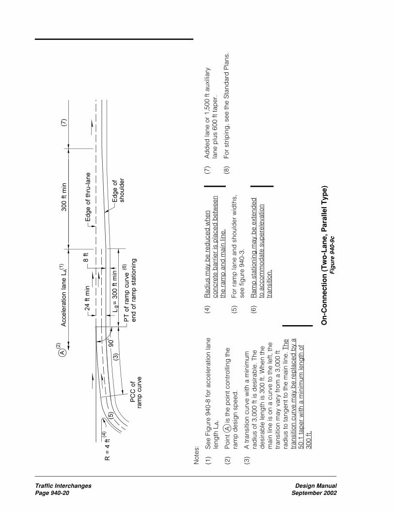
Traffic Interchanges Design ManualPage 940-20 September 2002
Not
es:
(1)
See
Fig
ure
940-
8 fo
r ac
cele
ratio
n la
nele
ngth
LA
.
(2)
Poi
nt A
is
the
poi
nt c
ontr
ollin
g th
era
mp
des
ign
spee
d.
(3)
A tr
ansi
tion
curv
e w
ith a
min
imum
rad
ius
of 3
,000
ft is
des
irab
le. T
hed
esira
ble
leng
th is
300
ft. W
hen
the
mai
n lin
e is
on
a cu
rve
to th
e le
ft, th
etr
ansi
tion
may
var
y fr
om a
3,0
00 ft
rad
ius
to ta
ngen
t to
the
mai
n lin
e. T
hetr
ansi
tion
curv
e m
ay b
e re
pla
ced
by
a50
:1 ta
per
with
a m
inim
um le
ngth
of
300
ft.
On
-Co
nn
ecti
on
(T
wo
-Lan
e, P
aral
lel T
ype)
Fig
ure
940
-9c
(4)
Rad
ius
may
be
red
uced
whe
nco
ncre
te b
arrie
r is
pla
ced
bet
wee
nth
e ra
mp
and
mai
n lin
e.
(5)
For
ram
p la
ne a
nd s
houl
der
wid
ths,
see
figur
e 94
0-3.
(6)
Ram
p s
tatio
ning
may
be
exte
nded
to a
ccom
mod
ate
sup
erel
evat
ion
tran
sitio
n.
(7)
Ad
ded
lane
or
1,50
0 ft
auxi
liary
lane
plu
s 60
0 ft
tap
er.
(8)
For
strip
ing
, see
the
Sta
ndar
d P
lans
.

Design Manual Traffic InterchangesSeptember 2002 Page 940-21
On
-Co
nn
ecti
on
(T
wo
-Lan
e, T
aper
Typ
e)F
igu
re 9
40-9
d
Not
es:
(1)
See
Fig
ure
940-
8 fo
r ac
cele
ratio
nla
ne le
ngth
LA
.
(2)
Poi
nt A
is
the
poi
nt c
ontr
ollin
g th
era
mp
des
ign
spee
d.
(3)
A tr
ansi
tion
curv
e w
ith a
min
imum
rad
ius
of 3
,000
ft is
des
irab
le. T
hed
esira
ble
leng
th is
300
ft. W
hen
the
mai
n lin
e is
on
a cu
rve
to th
ele
ft, th
e tr
ansi
tion
may
var
y fr
om a
3,00
0 ft
rad
ius
to ta
ngen
t to
the
mai
n lin
e.
(4)
Rad
ius
may
be
red
uced
whe
nco
ncre
te b
arrie
r is
pla
ced
bet
wee
nth
e ra
mp
and
mai
n lin
e.
(5)
For
ram
p la
ne a
nd s
houl
der
wid
ths,
see
figur
e 94
0-3.
(6)
Ap
pro
xim
ate
ang
le to
est
ablis
h ra
mp
alig
nmen
t.
(7)
Ad
ded
lane
or
1,50
0 ft
auxi
liary
lane
plu
s 60
0 ft
tap
er.
(8)
For
strip
ing
, see
the
Sta
ndar
d P
lans
.

Traffic Interchanges Design ManualPage 940-22 September 2002
Deceleration Lane lengthFigure 940-10
Highway Design
Ramp Design Speed (mph)
Speed (mph) 0 15 20 25 30 35 40 45 50 60 70
30 235 200 170 140 35 280 250 210 185 150 40 320 295 265 235 185 155 45 385 350 325 295 250 220 155 50 435 405 385 355 315 285 225 175 55 480 455 440 410 380 350 285 235 180 60 530 500 480 460 430 405 350 300 240 65 570 540 520 500 470 440 390 340 280 185 70 615 590 570 550 520 490 440 390 340 240
80 735 710 690 670 640 610 555 510 465 360 265
Minimum Deceleration Length (ft)
Grade Up Grade Down Grade
3% to less than 5%
0.9 1.2
5% or more 0.8 1.35
Adjustment Factors for Grades Greater than 3%

Design Manual Traffic InterchangesSeptember 2002 Page 940-23
Notes:(1) The reserve area length (L) is not less than:
Main Line Design Speed (mph) 40 45 50 55 60 65 70 80
L (ft) 25 30 35 40 45 50 55 70
(2) Z= , Design speed is for the main line.
(3) R may be reduced, when protected by an impact attenuator.
Gore Area CharacteristicsFigure 940-11a
Design Speed2
Edge of shoulder
Ramp
Edge of traveled way
Painted nose
Physical nose
Reserve area(1)
Gore nose
Edge of traveled way
Edge of shoulder
Z(2)
1
Z(2)
1R = 4 ft min(3)
Edge of thru-lane Edge of shoulder
Shoulder plus 2 ft
4 ft min
Shoulder width
12 ftL(1)
Edge of shoulderEdge of traveled way
Single-Lane Off-Connections No Lane Reduction

Traffic Interchanges Design ManualPage 940-24 September 2002
Notes:(1) The reserve area length (L) is not less than:
Main Line Design Speed (mph) 40 45 50 55 60 65 70 80
L (ft) 25 30 35 40 45 50 55 70
(2) Z= , Design speed is for the main line.
(3) R may be reduced, when protected by an impact attenuator.
Gore Area CharacteristicsFigure 940-11b
Design Speed2
Edge of shoulder
Ramp
Edge of traveled way
Painted nose
Physical nose
Reserve area(1)
Gore nose
Edge of traveled way
Edge of shoulder
Single-Lane, One-Lane Reduction Off-Connections
and All Two-Lane Off-Connections
Shoulder plus 2 ft
4 ftZ(2)
1
Edge of thru-lane
Edge of shoulderEdge of traveled way
12 ft
L(1)
Edge of shoulder
Shoulder width
R = 4 ft min(3)
4 ft min
50
1
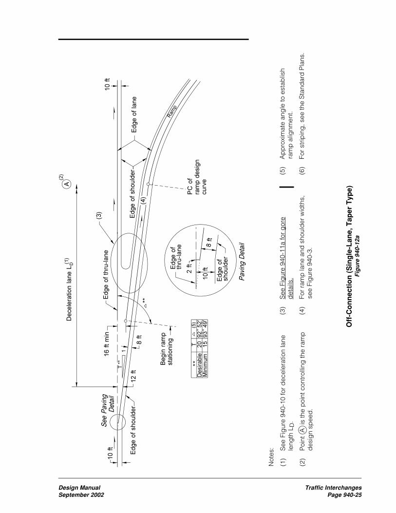
Design Manual Traffic InterchangesSeptember 2002 Page 940-25
Off
-Co
nn
ecti
on
(S
ing
le-L
ane,
Tap
er T
ype)
Fig
ure
940
-12a
Not
es:
(1)
See
Fig
ure
940-
10 fo
r d
ecel
erat
ion
lane
leng
th L
D.
(2)
Poi
nt A
is
the
poi
nt c
ontr
ollin
g th
e ra
mp
des
ign
spee
d.
(3)
See
Fig
ure
940-
11a
for
gor
ed
etai
ls.
(4)
For
ram
p la
ne a
nd s
houl
der
wid
ths,
see
Fig
ure
940-
3.
(5)
Ap
pro
xim
ate
ang
le to
est
ablis
hra
mp
alig
nmen
t.
(6)
For
strip
ing
, see
the
Sta
ndar
d P
lans
.
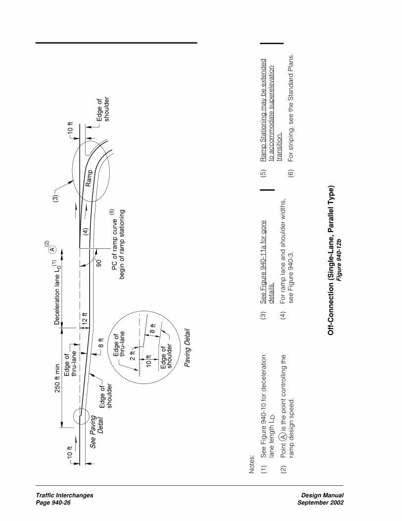
Traffic Interchanges Design ManualPage 940-26 September 2002
Not
es:
(1)
See
Fig
ure
940-
10 fo
r d
ecel
erat
ion
lane
leng
th L
D.
(2)
Poi
nt A
is
the
poi
nt c
ontr
ollin
g th
era
mp
des
ign
spee
d.
Off
-Co
nn
ecti
on
(S
ing
le-L
ane,
Par
alle
l Typ
e)F
igu
re 9
40-1
2b
(3)
See
Fig
ure
940-
11a
for
gor
ed
etai
ls.
(4)
For
ram
p la
ne a
nd s
houl
der
wid
ths,
see
Fig
ure
940-
3.
(5)
Ram
p S
tatio
ning
may
be
exte
nded
to a
ccom
mod
ate
sup
erel
evat
ion
tran
sitio
n.
(6)
For
strip
ing
, see
the
Sta
ndar
d P
lans
.

Design Manual Traffic InterchangesSeptember 2002 Page 940-27
Not
es:
(1)
See
Fig
ure
940-
10 fo
r d
ecel
erat
ion
lane
leng
th L
D.
(2)
Poi
nt A
is
the
poi
nt c
ontr
ollin
g th
e ra
mp
des
ign
spee
d.
(3)
See
Fig
ure
940-
11b
for
gor
e d
etai
ls.
(4)
For
ram
p la
ne a
nd s
houl
der
wid
ths,
see
Fig
ure
940-
3.
Off
-Co
nn
ecti
on
(S
ing
le-L
ane,
On
e-L
ane
Red
uct
ion
)F
igu
re 9
40-1
2c(5)
Ap
pro
xim
ate
ang
le to
est
ablis
hra
mp
alig
nmen
t.
(6)
Aux
iliar
y la
ne b
etw
een
clos
ely
spac
ed in
terc
hang
es to
be
dro
pp
ed.
(7)
For
strip
ing
, see
the
Sta
ndar
d P
lans
.

Traffic Interchanges Design ManualPage 940-28 September 2002
Not
es:
(1)
See
Fig
ure
940-
10 fo
r d
ecel
erat
ion
lane
leng
th L
D.
(2)
Poi
nt A
is
the
poi
nt c
ontr
ollin
g th
era
mp
des
ign
spee
d.
(3)
See
Fig
ure
940-
11b
for
gor
e d
etai
ls.
Off
-Co
nn
ecti
on
(T
wo
-Lan
e, T
aper
Typ
e)F
igu
re 9
40-1
2d
(4)
For
ram
p la
ne a
nd s
houl
der
wid
ths,
see
Fig
ure
940-
3.
(5)
Ap
pro
xim
ate
ang
le to
est
ablis
h ra
mp
alig
nmen
t.
(6)
Lane
to b
e d
rop
ped
or
auxi
liary
lane
with
a m
inim
um le
ngth
of
1,50
0 ft
with
a 3
00 ft
tap
er.
(7)
For
strip
ing
, see
the
Sta
ndar
dP
lans
.

Design Manual Traffic InterchangesSeptember 2002 Page 940-29
Not
es:
(1)
See
Fig
ure
940-
10 fo
r d
ecel
erat
ion
lane
leng
th L
D.
(2)
Poi
nt A
is
the
poi
nt c
ontr
ollin
g th
e ra
mp
des
ign
spee
d.
(3)
See
Fig
ure
940-
11b
for
gor
e d
etai
ls.
Off
-Co
nn
ecti
on
(T
wo
-Lan
e, P
aral
lel T
ype)
Fig
ure
940
-12e
(4)
For
ram
p la
ne a
nd s
houl
der
wid
ths,
see
Fig
ure
940-
3.
(5)
Ram
p s
tatio
ning
may
be
exte
nded
to a
ccom
mod
ate
sup
erel
evat
ion
tran
sitio
n.
(6)
Lane
to b
e d
rop
ped
or
auxi
liary
lane
with
a m
inim
um le
ngth
of 1
,500
ft w
itha
300
ft ta
per
.
(7)
For
strip
ing
, see
the
Sta
ndar
d P
lans
.

Traffic Interchanges Design ManualPage 940-30 September 2002
Co
llect
or
Dis
trib
uto
r (O
ute
r S
epar
atio
ns)
Fig
ure
940
-13a
Not
es:
(1)
With
just
ifica
tion,
the
conc
rete
bar
rier
may
be
pla
ced
with
2 ft
bet
wee
n th
e ed
ge
of e
ither
sho
uld
er a
nd th
e fa
ce o
f bar
rier.
The
min
imum
wid
th b
etw
een
the
edg
e of
thro
ugh-
shou
lder
and
the
edg
e of
C-D
roa
d s
houl
der
will
be
red
uced
to 6
ft,
and
the
rad
ius
at th
e no
se w
ill b
e re
duc
ed to
3ft.
(2)
For
colle
ctor
dis
trib
utor
roa
d la
ne a
nd s
houl
der
wid
ths,
see
ram
p la
ne a
nd s
houl
der
wid
ths,
Fig
ure
940-
3.
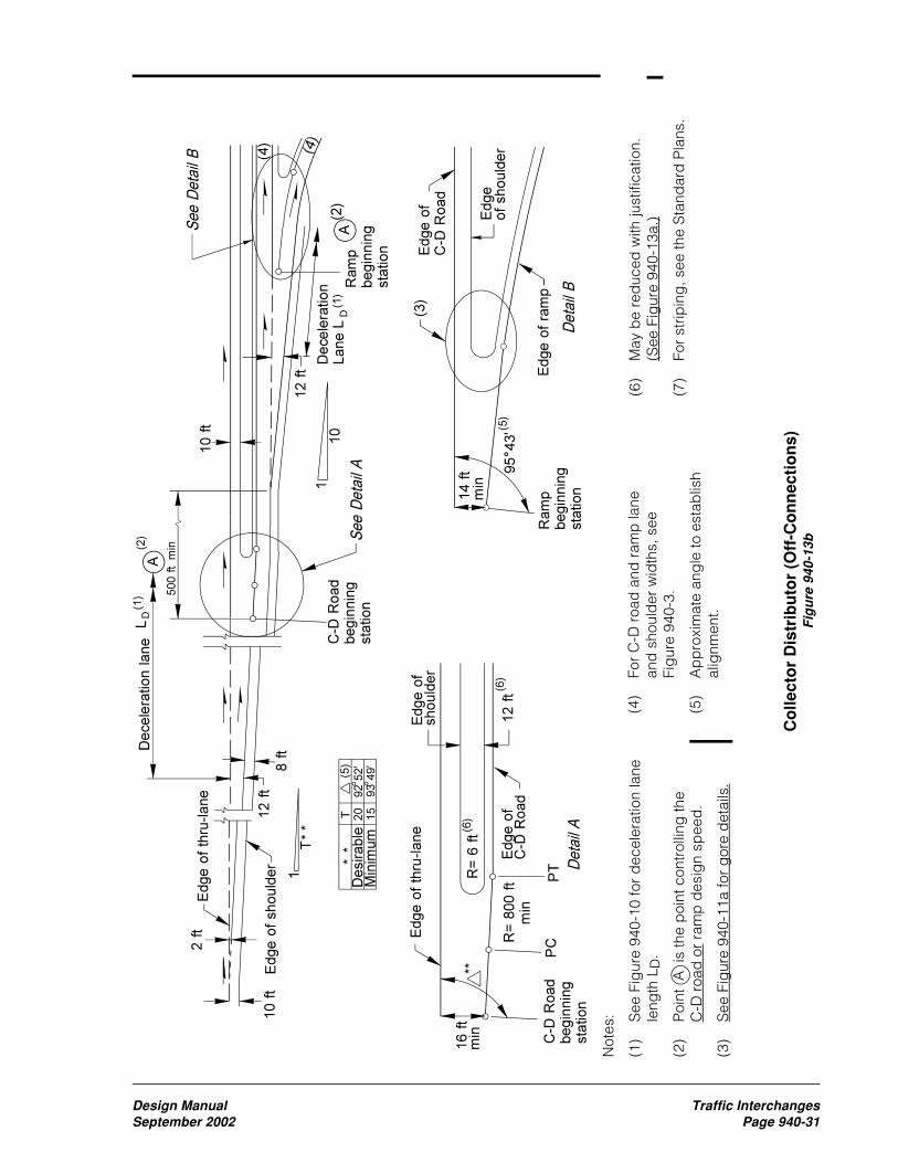
Design Manual Traffic InterchangesSeptember 2002 Page 940-31
Co
llect
or
Dis
trib
uto
r (O
ff-C
on
nec
tio
ns)
Fig
ure
940
-13b
(4)
For
C-D
roa
d a
nd r
amp
lane
and
sho
uld
er w
idth
s, s
eeFi
gur
e 94
0-3.
(5)
Ap
pro
xim
ate
ang
le to
est
ablis
hal
ignm
ent.
Not
es:
(1)
See
Fig
ure
940-
10 fo
r d
ecel
erat
ion
lane
leng
th L
D.
(2)
Poi
nt A
is
the
poi
nt c
ontr
ollin
g th
eC
-D r
oad
or
ram
p d
esig
n sp
eed
.
(3)
See
Fig
ure
940-
11a
for
gor
e d
etai
ls.
(6)
May
be
red
uced
with
just
ifica
tion.
(See
Fig
ure
940-
13a.
)
(7)
For
strip
ing
, see
the
Sta
ndar
d P
lans
.

Traffic Interchanges Design ManualPage 940-32 September 2002
Co
llect
or
Dis
trib
uto
r (O
n-C
on
nec
tio
ns)
Fig
ure
940
-13c
Not
es:
(1)
See
Fig
ure
940-
8 fo
r ac
cele
ratio
n la
nele
ngth
LA
.
(2)
Poi
nt A
is
the
poi
nt c
ontr
ollin
g th
e ra
mp
des
ign
spee
d.
(3)
A tr
ansi
tion
curv
e w
ith a
min
imum
rad
ius
of 3
,000
ft is
des
irab
le. T
hed
esira
ble
leng
th is
300
ft. W
hen
the
C-D
roa
d is
on
a cu
rve
to th
e le
ft,th
e tr
ansi
tion
may
var
y fr
om a
3,0
00ft
rad
ius
to ta
ngen
t to
the
C-D
roa
d.
(4)
For
C-D
roa
d a
nd r
amp
lane
and
shou
lder
wid
ths,
see
Fig
ure
940-
3.
(5)
Ap
pro
xim
ate
ang
le to
est
ablis
hal
ignm
ent.
(6)
May
be
red
uced
with
just
ifica
tion.
(See
Fig
ure
940-
13a.
)
(7)
For
strip
ing
, see
the
Sta
ndar
d P
lans
.

Design Manual Traffic InterchangesSeptember 2002 Page 940-33
Lo
op
Ram
ps
Co
nn
ecti
on
sF
igu
re 9
40-1
4
Not
es:
(1)
See
Fig
ure
940-
15 fo
r re
qui
red
min
imum
wea
ving
leng
th.
(2)
For
min
imum
ram
p la
ne a
nd s
houl
der
wid
ths,
see
Fig
ure
940-
3.
(3)
See
Fig
ure
940-
11b
for
gor
e d
etai
ls.

Traffic Interchanges Design ManualPage 940-34 September 2002
Length of Weaving SectionsFigure 940-15

Design Manual Traffic InterchangesSeptember 2002 Page 940-35
Tem
po
rary
Ram
ps
Fig
ure
940
-16

Traffic Interchanges Design ManualPage 940-36 September 2002
Inte
rch
ang
e P
lan
Fig
ure
940
-17

A
(%) 40 60 80 100 120 140 160 180 200 220 240 260 280 300
2 3 3 3 3 3 3 3 3 3 3 30 70 110 150
3 3 3 3 3 3 3 20 60 100 140 180 220 260 300
4 3 3 3 3 15 55 95 135 175 215 256 300 348 400
5 3 3 3 20 60 100 140 180 222 269 320 376 436 500
6 3 3 10 50 90 130 171 216 267 323 384 451 523 600
7 3 3 31 71 111 152 199 252 311 376 448 526 610 700
8 3 8 48 88 128 174 228 288 356 430 512 601 697 800
9 3 20 60 100 144 196 256 324 400 484 576 676 784 900
10 3 30 70 111 160 218 284 360 444 538 640 751 871 1000
11 3 38 78 122 176 240 313 396 489 592 704 826 958 1100
12 5 45 85 133 192 261 341 432 533 645 768 901 1045 1200
13 11 51 92 144 208 283 370 468 578 699 832 976 1132 1300
14 16 56 100 156 224 305 398 504 622 753 896 1052 1220 1400
15 20 60 107 167 240 327 427 540 667 807 960 1127 1307 1500
16 24 64 114 178 256 348 455 576 711 860 1024 1202 1394 1600
17 27 68 121 189 272 370 484 612 756 914 1088 1277 1481 1700
18 30 72 128 200 288 392 512 648 800 968 1152 1352 1568 1800
19 33 76 135 211 304 414 540 684 844 1022 1216 1427 1655 1900
20 35 80 142 222 320 436 569 720 889 1076 1280 1502 1742 2000
21 37 84 149 233 336 457 597 756 933 1129 1344 1577 1829 2100
22 39 88 156 244 352 479 626 792 978 1183 1408 1652 1916 2200
23 41 92 164 256 368 501 654 828 1022 1237 1472 1728 2004 2300
24 43 96 171 267 384 523 683 864 1067 1291 1536 1803 2091 2400
25 44 100 178 278 400 544 711 900 1111 1344 1600 1878 2178 2500
Stopping Sight Distance, S (ft)
Minimum Length of Vertical Curve, L (ft)
Sight Distances for Crest Vertical CurvesFigure 1020-20
900ASL
2
=
A900-2SL =
when S <L
when S <L
Where:S = Stopping sight distance.A = Algebraic difference in grade.L = Minimum vertical curve length
Based on an eye height of 4.5 ft and anobject height of 0 ft.
Design Manual Bicycle FacilitiesSeptember 2002 Page 1020-25

Where:S = Sight distance in feetR = Radius of center line inside lane in feetM = Distance from center line inside lane in feet
R
(ft) 40 60 80 100 120 140 160 180 200 220 240 260 280 300
25 7.6 15.9
50 3.9 8.7 15.2 23.0 31.9 41.5
75 2.7 5.9 10.4 16.1 22.7 30.4 38.8 47.8 57.4 67.2
95 2.1 4.7 8.3 12.9 18.3 24.6 31.7 39.5 47.9 56.9 66.2 75.9 85.8
125 1.6 3.6 6.3 9.9 14.1 19.1 24.7 31.0 37.9 45.4 53.3 61.7 70.5 79.7
150 1.3 3.0 5.3 8.3 11.8 16.0 20.8 26.2 32.1 38.6 45.5 52.9 60.7 69.0
175 1.1 2.6 4.6 7.1 10.2 13.8 18.0 22.6 27.8 33.4 39.6 46.1 53.1 60.4
200 1.0 2.2 4.0 6.2 8.9 12.1 15.8 19.9 24.5 29.5 34.9 40.8 47.0 53.7
225 0.9 2.0 3.5 5.5 8.0 10.8 14.1 17.8 21.9 26.4 31.2 36.5 42.2 48.2
250 0.8 1.8 3.2 5.0 7.2 9.7 12.7 16.0 19.7 23.8 28.3 33.0 38.2 43.7
275 0.7 1.6 2.9 4.5 6.5 8.9 11.6 14.6 18.0 21.7 25.8 30.2 34.9 39.9
300 0.7 1.5 2.7 4.2 6.0 8.1 10.6 13.4 16.5 19.9 23.7 27.7 32.1 36.7
350 0.6 1.3 2.3 3.6 5.1 7.0 9.1 11.5 14.2 17.1 20.4 23.9 27.6 31.7
400 0.5 1.1 2.0 3.1 4.5 6.1 8.0 10.1 12.4 15.0 17.9 20.9 24.3 27.8
500 0.4 0.9 1.6 2.5 3.6 4.9 6.4 8.1 10.0 12.1 14.3 16.8 19.5 22.3
600 0.3 0.7 1.3 2.1 3.0 4.1 5.3 6.7 8.3 10.1 12.0 14.0 16.3 18.7
700 0.3 0.6 1.1 1.8 2.6 3.5 4.6 5.8 7.1 8.6 10.3 12.0 14.0 16.0
800 0.2 0.6 1.0 1.6 2.2 3.1 4.0 5.1 6.2 7.6 9.0 10.5 12.2 14.0
900 0.2 0.5 0.9 1.4 2.0 2.7 3.6 4.5 5.5 6.7 8.0 9.4 10.9 12.5
1000 0.2 0.4 0.8 1.2 1.8 2.4 3.2 4.0 5.0 6.0 7.2 8.4 9.8 11.2
Stopping Sight Distance, S (ft)
Minimum Lateral Clearance, M (ft)
Lateral Clearance on Horizontal CurvesFigure 1020-21
Bicycle Facilities Design ManualPage 1020-26 September 2002
Height of eye: 4.50 ftHeight of object: 0.0 ftLine of sight is normally 2.25 ft abovecenter line of inside lane at point ofobstruction provided no vertical curveis present in horizontal curve.
Center of lane
Obstruction or
back slope
Line of
sight
Sight distance (S)
Radius
M
S ≤ Length of curveAngle is expressed in degrees
M R 1 COS28.65 S
R= −
SR
28.65COS
1 R M
R=
− −

Design Manual BridgesSeptember 2002 Page 1120-1
1120 Bridges
• A constant bridge width (without taperedsections)
• A tangential approach alignment of sufficientlength to not require superelevation on thebridge
• A crest vertical curve profile that willfacilitate drainage
• An adequate construction staging area
1120.04 Bridge Site DesignElements(1) Structural CapacityThe structural capacity of a bridge is a measureof the structure’s ability to carry vehicle loads.For new bridges, the bridge designer choosesthe design load that determines the structuralcapacity. For existing bridges, the structuralcapacity is calculated to determine the “loadrating” of the bridge. The load rating is usedto determine whether or not a bridge is “posted”for legal weight vehicles or if the bridge is“restricted” for overweight permit vehicles.
(a) New Structures. All new structures thatcarry vehicular loads are designed to HL-93notional live load in accordance with AASHTOLRFD Bridge Design Specifications or HS-25live loading in accordance with the AASHTOStandard Specifications for Highway Bridges.
(b) Existing Structures. When the StructuralCapacity column of a design matrix applies to theproject, request a Structural Capacity Report fromthe Risk Reduction Engineer in the Bridge andStructures Office at mail stop 47341. The reportwill state:
• The structural capacity status of the structureswithin the project limits.
• What action, if any, is appropriate.
• Whether a deficient bridge is included in thesix-year or 20 year plans for replacement orrehabilitation under the P2 program and, ifso, in which biennium the P2 project is likelyto be funded.
1120.01 General1120.02 References1120.03 Bridge Location1120.04 Bridge Site Design Elements1120.05 Documentation
1120.01 GeneralA bridge is a structure having a clear span of20 ft or more. Bridge design is the responsibilityof the Bridge and Structures Office in Olympia.A project file is required for all bridgeconstruction projects. The Bridge Officedevelops a preliminary bridge plan for a newor modified structure in collaboration with theregion. This chapter provides basic designconsiderations for the development of this plan.Unique staging requirements, constructibilityissues, and other considerations are addressedduring the development of this plan. Contact theBridge Office early in the planning stage onissues that might affect the planned project.
1120.02 ReferencesBridge Design Manual, M 23-50, WSDOT
Local Agency Guidelines, M 36-63, WSDOT
Manual on Uniform Traffic Control Devices forStreets and Highways (MUTCD), USDOT,Washington DC, 1988, including the WashingtonState Modifications to the MUTCD, M 24-01,WSDOT, 1996
A Policy on Geometric Design of Highways andStreets, 2001, AASHTO
Traffic Manual, M 51-02, WSDOT
1120.03 Bridge LocationBridges are located to conform to the alignmentof the highway. Providing the followingconditions can simplify design efforts, minimizeconstruction activities, and reduce structure costs:
• A perpendicular crossing
• The minimum required horizontal andvertical clearances

Bridges Design ManualPage 1120-2 September 2002
Include the Structural Capacity Report in thedesign documentation file.
The considerations used to evaluate the structuralcapacity of a bridge are as follows:
1. On National Highway System (NHS) routes(including Interstate routes):
• Operating load rating is at least 36 tons(which is equal to HS-20).
• The bridge is not permanently posted forlegal weight vehicles.
• The bridge is not permanently restricted forvehicles requiring overweight permits.
2. On non-NHS routes:
• The bridge is not permanently posted forlegal weight vehicles.
• The bridge is not permanently restricted forvehicles requiring overweight permits.
(2) Bridge Widths for Structures(a) New Structures. Full design level widthsare provided on all new structures. See Chapter440. All structures on city or county routescrossing over a state highway must conform tothe Local Agency Guidelines. Use local city orcounty adopted and applied criteria when theirminimums exceed state criteria.
(b) Existing Structures. See the designmatrices in Chapter 325 for guidance.
(3) Horizontal ClearanceHorizontal clearance for structures is the distancefrom the edge of the traveled way to bridge piersand abutments, bridge rail ends, or bridge endembankment slopes. Minimum distances for thisclearance vary depending on the type of structure.The Bridge Design Manual provides guidance onhorizontal clearance.
(4) MediansFor multilane highways, the minimum medianwidths for new bridges are as shown in Chapters430 and 440. An open area between two bridgesis undesirable when the two roadways areseparated by a median width of 26 ft or less.The preferred treatment is to provide a new,single structure that spans the area between the
roadways. When this is impractical, considerwidening the two bridges on the median sidesto reduce the open area to 6 in. When neitheroption is practical, consider installing nettingor other elements to enclose the area betweenthe bridges. Consideration and analysis of allsite factors are necessary if installation of nettingor other elements is proposed. Document thisevaluation in the design documentation file andobtain the approval of the State Design Engineer.
(5) Vertical ClearanceVertical clearance is the critical height under astructure that will safely accommodate vehicularand rail traffic based on its design characteristics.This height is the least height available from thelower roadway surface (including usableshoulders), or the plane of the top of the rails,to the bottom of the bridge. Usable shouldersare the design shoulders for the roadway anddo not include paved widened areas that mayexist under the structure.
(a) Minimum Clearance for New Structures.For new structures, the minimum verticalclearances are as follows:
1. A bridge over a roadway. The minimumvertical clearance is 16.5 ft.
2. A bridge over a railroad track. Theminimum vertical clearance is 23.5 ft.Vertical clearance is provided for the widthof the railroad freight car. (See Figure1120-2a.) Coordinate railroad clearanceissues with the WSDOT Railroad LiaisonEngineer.
3. A pedestrian bridge over a roadway.The minimum vertical clearance is 17.5 ft.
(b) Minimum Clearance for ExistingStructures. The criteria used to evaluate thevertical clearance of existing structures dependson the work that is being done on or under thatstructure. When evaluating an existing structureon the Interstate system, see 1120.04(5)(d)“Coordination.” This guidance applies to bridgeclearances over state highways and under statehighways at interchanges. For state highwaysover local roads and streets, city or countyvertical clearance requirements may be used asminimum design criteria. See Figure 1120-1 fora table of bridge vertical clearances.

Design Manual BridgesSeptember 2002 Page 1120-3
1. For a project that will widen an existingstructure over a highway or where thehighway will be widened under an existingstructure, the vertical clearance can be aslittle as 16.0 ft on the Interstate System orother freeways, or 15.5 ft on nonfreewayroutes. An approved deviation is required forclearance less than 16.0 ft on Interstate routesor other freeways, and 15.5 ft on nonfreewayroutes.
2. For a planned resurfacing of the highwayunder an existing bridge, if the clearance willbe less than 16.0 ft on the Interstate Systemor other freeways and 15.5 ft on nonfreewayroutes, evaluate the following options andinclude in a deviation request:
• Pavement removal and replacement.
• Roadway excavation and reconstructionto lower the profile of the roadway.
• Providing a new bridge with the requiredvertical clearance.
Reducing roadway paving and surfacingthickness under the bridge to achieve theminimum vertical clearance can causeaccelerated deterioration of the highwayand is not recommended. Elimination of theplanned resurfacing in the immediate areaof the bridge might be a short term solutionif recommended by the region’s MaterialsEngineer. Solutions that include milling theexisting surface followed by overlay or inlaymust be approved by the region’s MaterialsEngineer to ensure that adequate pavementstructure is provided.
3. For other projects that include an existingbridge where no widening is proposed on orunder the bridge, and the project does notaffect vertical clearance, the clearance canbe as little as 14.5 ft. For these projects,document the clearance to the designdocumentation file.
4. For an existing structure over a railroadtrack, the vertical clearance can be as littleas 22.5 ft. (See Figure 1120-2b.) A lesserclearance can be used with the agreement ofthe railroad company and the WashingtonState Utilities and TransportationCommission. Coordinate railroad clearanceissues with the WSDOT Railroad LiaisonEngineer.
(c) Signing. Low clearance warning signsare necessary when the vertical clearance ofan existing bridge is less than 15 ft 3 in. Otherrequirements for low clearance signing arecontained in the Manual on Uniform TrafficControl Devices and the Traffic Manual.
(d) Coordination. The Interstate system isused by the Department of Defense (DOD) forthe conveyance of military traffic. The MilitaryTraffic Management Command TransportationEngineering Agency (MTMCTEA) representsthe DOD in public highway matters. TheMTMCTEA has an inventory of verticalclearance deficiencies over the Interstate systemin Washington State. Contact the MTMCTEA,through FHWA, if any of the following changesare proposed to these bridges:
• A project would create a new deficiency ofless than 16.0 ft vertical clearance over anInterstate highway.
• The vertical clearance over the Interstateis already deficient (less than 16.0 ft) anda change (increase or decrease) to verticalclearance is proposed.
Coordination with MTMCTEA is required forthese changes on all rural Interstate highways andfor one Interstate route through each urban area.

Bridges Design ManualPage 1120-4 September 2002
Interstate and Other Freeways 1
New Bridge > 16.5 ft 2
Widening Over or > 16 ft 2
Under Existing Bridge < 16 ft 4
Resurfacing Under > 16 ft 2
Existing Bridge < 16 ft 4
Other with No Change >14.5 3
to Vertical Clearance <14.5 4
Nonfreeway Routes
New Bridge >16.5 ft 2
Widening Over or >15.5 ft 2
Under Existing Bridge <15.5 ft 4
Resurfacing Under >15.5 ft 2
Existing Bridge <15.5 ft 4
Other with No Change > 14.5 ft 3
to Vertical Clearance < 14.5 ft 4
Bridge Over Railroad Tracks7
New Bridge > 23.5 ft 2
Existing Bridge > 22.5 ft 2< 22.5 ft 4, 5
Pedestrian Bridge Over Roadway
New Bridge > 17.5 ft 2
Existing Bridge 6Notes:1. Applies to all bridge vertical clearancesover highways and under highways atinterchanges2. No documentation required3. Document to design documentation file4. Approved deviation required5. Requires written agreement betweenrailroad company and Washington State Utilitiesand Transportation Commission6. Use the same criteria as other existingbridges previously listed in the figure7. See Figure 1120-2a and 2b
Bridge Vertical ClearancesFigure 1120-1
(6) Bridge Approach SlabBridge approach slabs are reinforced concretepavement installed across the full width of thebridge ends. They provide a stable transition fromnormal roadway cross section to the bridge endsand compensate for differential expansion andcontraction of the bridge and the roadway. Bridgeapproach slabs are provided on all new bridges.If an existing bridge is being widened and ithas an approach slab, slabs are required on thewidenings. The region, with the concurrence ofthe State Geotechnical Engineer and the StateBridge Engineer, may decide to omit bridgeapproach slabs.
(7) Pedestrian and Bicycle FacilitiesWhen pedestrians or bicyclists are anticipatedon bridges, provide facilities consistent withguidance in Chapters 1020 and 1025.
(8) Bridge Rail End TreatmentPlans for new bridge construction and bridge railmodifications include provisions for theconnection of traffic barriers to the bridge rail.Indicate the preferred traffic barrier type andconnection during the review of the bridgepreliminary plan.
(9) Bridge Slope ProtectionSlope protection provides a protective andaesthetic surface for exposed slopes underbridges. Slope protection is normally providedunder:
• Structures over state highways
• Structures within an interchange
• Structures over other public roads unlessrequested otherwise by the public agency
• Railroad overcrossings, if requested by therailroad
Slope protection is usually not provided underpedestrian structures. The type of slope protectionis selected at the bridge preliminary plan stage.Typical slope protection types are concrete slopeprotection, semi-open concrete masonry, andrubble stone.
Pro
ject
Typ
e
Doc
umen
tati
onR
equi
rem
ent
(see
not
es)
Ver
tica
lC
lear
ance

Design Manual BridgesSeptember 2002 Page 1120-5
(10) Slope Protection atWatercrossingsThe WSDOT Headquarters (HQ) HydraulicsBranch determines the slope protectionrequirements for structures that cross waterways.The type, limits, and quantity of the slopeprotection are shown on the bridge preliminaryplan.
(11) Protective Screening forHighway StructuresThe Washington State Patrol classifies thethrowing of an object from a highway structureas an assault, not an accident. Therefore, recordsof these assaults are not contained in the Patrol’saccident databases. Contact the region’sMaintenance Engineer’s office and theWashington State Patrol for the history ofreported incidents.
Protective screening might reduce the numberof incidents but will not stop a determinedindividual. Enforcement provides the mosteffective deterrent.
Installation of protective screening is analyzed ona case-by-case basis at the following locations:
• On existing structures where there is ahistory of multiple incidents of objects beingdropped or thrown and enforcement has notchanged the situation.
• On a new structure near a school, aplayground, or where frequently used bychildren not accompanied by adults.
• In urban areas, on a new structure used bypedestrians where surveillance by local lawenforcement personnel is not likely.
• On new structures with walkways whereexperience on similar structures within a1 mile radius indicates a need.
• On structures over private property that issubject to damage, such as buildings orpower stations.
In most cases, the installation of a protectivescreen on a new structure can be postponed untilthere are indications of need.
Submit all proposals to install protectivescreening on structures to the State DesignEngineer for approval. Contact the Bridge andStructures Office for approval to attach screeningto structures and for specific design and mountingdetails.
1120.05 DocumentationInclude the following items in the designdocumentation file. See Chapter 330.
� Structural Capacity Report
� Evaluation of need and approval forenclosing the area between bridges
� Correspondence involving the MTMCTEA
� Justification for eliminating an overlay inthe vicinity of a bridge
� Final Foundation Report
� Justification and HQ concurrence foromitting approach slabs
� Analysis of need and approval forprotective screening on highway structures
� Railroad agreement allowing less than22.5 ft vertical clearance
� Approval of proposal to mill and existingservice
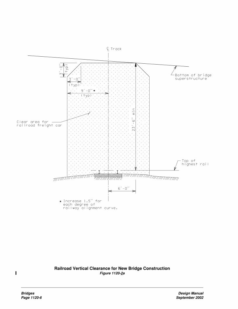
Bridges Design ManualPage 1120-6 September 2002
Railroad Vertical Clearance for New Bridge ConstructionFigure 1120-2a

Design Manual BridgesSeptember 2002 Page 1120-7
Railroad Vertical Clearance for Existing Bridge ModificationsFigure 1120-2b


Design Manual Hydraulic DesignSeptember 2002 Page 1210-1
1210 Hydraulic Design
1210.01 General1210.02 References1210.03 Hydraulic Considerations1210.04 Safety Considerations1210.05 Design Responsibility
1210.01 GeneralHydraulic design factors can significantlyinfluence the corridor, horizontal alignment,grade, location of interchanges, and the necessaryappurtenances required to convey water across,along, away from, or to a highway or highwayfacility. An effective hydraulic design conveyswater in the most economical, efficient, andpractical manner to ensure the public safetywithout incurring excessive maintenance costsor appreciably damaging the highway orhighway facility, adjacent property, or thetotal environment.
This chapter is intended to serve as a guide tohighway designers so they can identify andconsider hydraulic related factors that impactthe design. Detailed criteria and methods thatgovern highway hydraulic design are inWSDOT’s Hydraulics Manual and HighwayRunoff Manual.
Some drainage, flood, and water qualityproblems can be easily recognized and resolved;others might require extensive investigationbefore a solution can be developed. Specialistsexperienced in hydrology and hydraulics cancontribute substantially to the planning andproject definition phases of a highway projectby recognizing potentially troublesome locations,making investigations and recommendingpractical solutions. Regions may request thatthe HQ Hydraulics Branch provide assistanceregarding hydraulic problems.
Since hydraulic factors can affect the design ofa proposed highway or highway facility from itsinception, consider these factors at the earliestpossible time during the planning phase.
In the project definition phase, begin coordinationwith all state and local governments and Indiantribes that issue or approve permits for theproject.
1210.02 References(1) Existing Criteria and ReferencesExisting criteria and additional information forhydraulic design requirements, analyses, andprocedures are contained in the followingreferences:
Hydraulics Manual, M 23-03, WSDOT
Highway Runoff Manual, M 31-16, WSDOT
Standard Plans for Road, Bridge and MunicipalConstruction, (Standard Plans) M 21-01,WSDOT
Standard Specifications for Road, Bridgeand Municipal Construction, (StandardSpecifications) M 41-10, Amendments,and General Special Provisions, WSDOT
Utilities Manual, M 22-87, Section 1-19, “StormDrainage,” WSDOT
(2) Special CriteriaSpecial criteria for unique projects are availableon request from the HQ Hydraulics Branch.
1210.03 Hydraulic Considerations(1) The Flood PlainEncroachment of a highway or highway facilityinto a flood plain might present significantproblems. A thorough investigation considersthe following:
(a) The effect of the design flood on thehighway or highway facility and the requiredprotective measures.
(b) The effect of the highway or highwayfacility on the upstream and downstream reachesof the stream and the adjacent property.

Hydraulic Design Design ManualPage 1210-2 September 2002
(c) Compliance with hydraulic relatedenvironmental concerns and hydraulic aspectsof permits from other governmental agencies perChapters 220 and 240.
Studies and reports published by the FederalEmergency Management Agency (FEMA) andthe Corps of Engineers are very useful for floodplain analysis. The HQ Hydraulics Branch hasaccess to all available reports and can provideany necessary information to the region.
(2) Stream CrossingsWhen rivers, streams, or surface waters (wetland)are crossed with bridges or culverts (includingopen bottom arches and three-sided box culverts),consider the following:
• Locating the crossing where the stream ismost stable.
• Effectively conveying the design flow(s) atthe crossing.
• Providing for passage of material transportedby the stream.
• The effects of backwater on adjacentproperty.
• Avoiding large skews at the crossing.
• The effects on the channel and embankmentstability upstream and downstream fromthe crossing.
• Location of confluences with other streamsor rivers.
• Fish and wildlife migration.
• Minimizing disturbance to the originalstreambed.
• Minimizing wetland impact.
Also see the Hydraulics Manual Chapter 8 forfurther design details.
(3) Channel ChangesIt is generally desirable to minimize the use ofchannel changes because ongoing liability andnegative environmental impacts might result.Channel changes are permissible when thedesigner determines that a reasonable, practicalalternative does not exist. When used, consider:
(a) Restoration of the original stream character-istics as nearly as practical. This includes:
• Meandering the channel change to retainits sinuosity.
• Maintaining existing stream slope andgeometry (including meanders) so streamvelocity and aesthetics do not change inundisturbed areas.
• Excavation, selection, and placement of bedmaterial to promote formation of a naturalpattern and prevent bed erosion.
• Retention of stream bank slopes.
• Retention or replacement of streamsidevegetation.
(b) The ability to pass the design flood.
(c) The effects on adjacent property.
(d) The effects on the channel and embankmentupstream and downstream from the channelchange.
(e) Erosion protection for the channel change.
(f) Environmental requirements such aswetlands, fish migration, and vegetationre-establishment.
Do not redirect flow from one drainage basin toanother. (Follow the historical drainage pattern.)
Consult the HQ Hydraulics Branch for the bestguidance when channel changes are considered.
(4) Roadway DrainageEffective collection and conveyance of stormwater is critical. Incorporate the most efficientcollection and conveyance system consideringinitial highway costs, maintenance costs, andlegal and environmental considerations. Ofparticular concern are:
(a) Combinations of vertical grade and trans-verse roadway slopes that might inhibit drainage.
(b) Plugging of drains on bridges as theresult of construction projects. This createsmaintenance problems and might cause pondingon the structure. The use of drains on structurescan be minimized by placing sag vertical curvesand crossovers in superelevation outside thelimits of the structure.

Design Manual Hydraulic DesignSeptember 2002 Page 1210-3
(c) See Chapter 630 for discussion of therelationship of roadway profiles to drainageprofiles.
(5) Subsurface DrainageSubsurface drainage installations control groundwater encountered at highway locations. Groundwater, as distinguished from capillary water, isfree water occurring in a zone of saturation belowthe ground surface. The subsurface dischargedepends on the effective hydraulic head and onthe permeability, depth, slope, thickness, andextent of the aquifer.
The solution of subsurface drainage problemsoften calls for specialized knowledge ofgeology and the application of soil mechanics.The region Materials Engineer evaluates thesubsurface conditions and includes findings andrecommendations for design in the geotechnicalreport.
Typical subdrain installations control seepagein cuts or hillsides, control base and shallowsubgrade drainage, or lower the ground watertable (in swampy areas, for example).
Design a system that will keep the stormwaterout of the subsurface system when stormwaterand subsurface drainage systems are combined.
(6) Subsurface Discharge of HighwayDrainageConsider subsurface discharge of highwaydrainage when it is a requirement of the localgovernment or when existing ground conditionsare favorable for this type of discharge system.Criteria for the design of drywells or subsurfacedrainage pipe for this type of application aredescribed in Chapter 6 of the Hydraulics Manual.The criteria for the design of infiltration pondsare described in the Highway Runoff Manual.
(7) Treatment of RunoffOn certain projects, effective quantity controlof runoff rates and removal of pollutants frompavement are intended to address flooding andwater quality impacts downstream. See theHighway Runoff Manual for specific criteriaon quantity and quality control of runoff.
1210.04 Safety ConsiderationsLocate culvert ends outside the Design ClearZone when practical. See Chapter 700 for culvertend treatments when this is impractical.
See Chapter 1460 regarding fencing for detentionponds and wetland mitigation sites.
1210.05 Design ResponsibilityChapter 1 of the Hydraulics Manual describesthe responsibilities of the regions and theHQ Hydraulics Branch relative to hydraulicdesign issues.

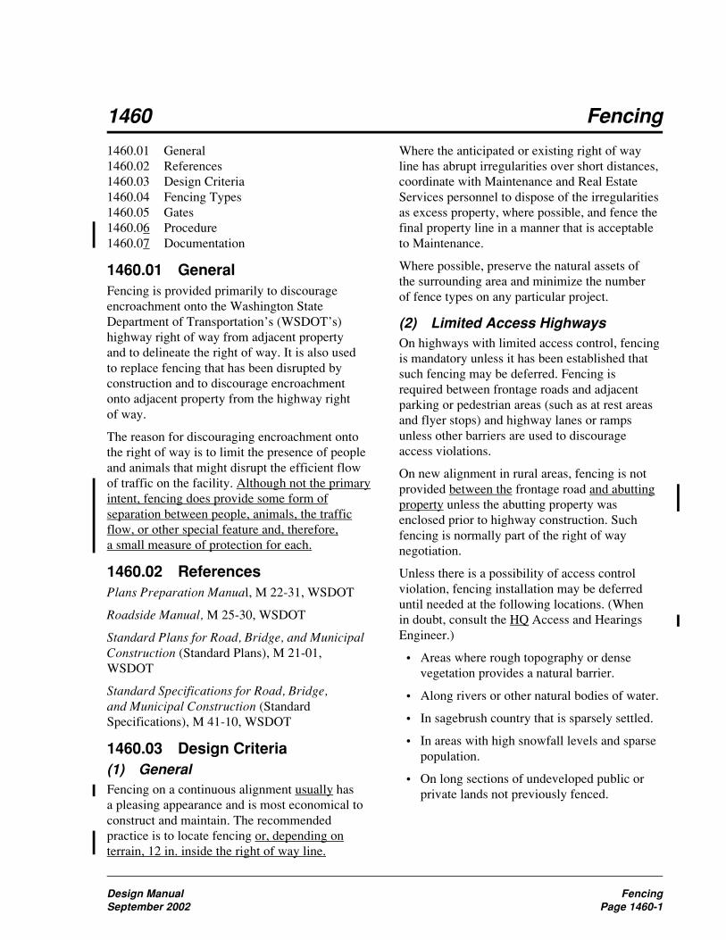
Design Manual FencingSeptember 2002 Page 1460-1
1460 Fencing
Where the anticipated or existing right of wayline has abrupt irregularities over short distances,coordinate with Maintenance and Real EstateServices personnel to dispose of the irregularitiesas excess property, where possible, and fence thefinal property line in a manner that is acceptableto Maintenance.
Where possible, preserve the natural assets ofthe surrounding area and minimize the numberof fence types on any particular project.
(2) Limited Access HighwaysOn highways with limited access control, fencingis mandatory unless it has been established thatsuch fencing may be deferred. Fencing isrequired between frontage roads and adjacentparking or pedestrian areas (such as at rest areasand flyer stops) and highway lanes or rampsunless other barriers are used to discourageaccess violations.
On new alignment in rural areas, fencing is notprovided between the frontage road and abuttingproperty unless the abutting property wasenclosed prior to highway construction. Suchfencing is normally part of the right of waynegotiation.
Unless there is a possibility of access controlviolation, fencing installation may be deferreduntil needed at the following locations. (Whenin doubt, consult the HQ Access and HearingsEngineer.)
• Areas where rough topography or densevegetation provides a natural barrier.
• Along rivers or other natural bodies of water.
• In sagebrush country that is sparsely settled.
• In areas with high snowfall levels and sparsepopulation.
• On long sections of undeveloped public orprivate lands not previously fenced.
1460.01 General1460.02 References1460.03 Design Criteria1460.04 Fencing Types1460.05 Gates1460.06 Procedure1460.07 Documentation
1460.01 GeneralFencing is provided primarily to discourageencroachment onto the Washington StateDepartment of Transportation’s (WSDOT’s)highway right of way from adjacent propertyand to delineate the right of way. It is also usedto replace fencing that has been disrupted byconstruction and to discourage encroachmentonto adjacent property from the highway rightof way.
The reason for discouraging encroachment ontothe right of way is to limit the presence of peopleand animals that might disrupt the efficient flowof traffic on the facility. Although not the primaryintent, fencing does provide some form ofseparation between people, animals, the trafficflow, or other special feature and, therefore,a small measure of protection for each.
1460.02 ReferencesPlans Preparation Manual, M 22-31, WSDOT
Roadside Manual, M 25-30, WSDOT
Standard Plans for Road, Bridge, and MunicipalConstruction (Standard Plans), M 21-01,WSDOT
Standard Specifications for Road, Bridge,and Municipal Construction (StandardSpecifications), M 41-10, WSDOT
1460.03 Design Criteria(1) GeneralFencing on a continuous alignment usually hasa pleasing appearance and is most economical toconstruct and maintain. The recommendedpractice is to locate fencing or, depending onterrain, 12 in. inside the right of way line.

Fencing Design ManualPage 1460-2 September 2002
(3) Managed Access HighwaysFencing is not required for managed accesshighways. When highway construction willdestroy the fence of an abutting property owner,originally constructed on private property, thecost of such replacement fencing may be includedin the right of way payment. When the fences ofseveral property owners will be impacted, it maybe cost-effective to replace the fences as part ofthe project.
If fencing is essential to safe operation of thehighway, it will be constructed and maintainedby the state. Examples of this are the separationof traveled highway lanes and adjacent facilitieswith parking or pedestrian areas such as restareas and flyer stops.
(4) Special SitesFencing is often needed at special sites such aspitsites, stockpiles, borrow areas, and storm waterdetention facilities.
It is recommended that storm water detentionfacilities and wetland mitigation sites be fenced ifall of the following conditions exist:
• The storm water detention facility or wetlandmitigation site is outside highway right ofway fencing.
• The slopes into the storm water detentionfacility or wetland mitigation site are 3H:1Vor steeper.
• The storm water detention facility or wetlandmitigation site is located near a school, park,trail, or other facility frequented by childrennot accompanied by an adult.
Fencing proposed at sites that will be outsideWSDOT right of way requires that localordinances be followed if they are more stringentthan WSDOT’s.
Fencing is not installed around storm waterdetention ponds within right of way fencing.
Other special sites where fencing may be requiredare addressed in the following chapters:
• 1020 Bicycle Facilities
• 1025 Pedestrian Design Considerations
• 1120 Bridges
The type and configuration of the fence isdetermined by the requirements of each situation.
1460.04 Fencing Types(1) Chain LinkInstallation of chain link fence is appropriatefor maximum protection against right of wayencroachment on sections of high volumehighways under the following conditions:
• Along an existing business district adjacentto a freeway.
• Between a freeway and an adjacent parallelcity street.
• At locations where existing streets have beencut off by freeway construction.
• At industrial areas.
• At large residential developments.
• At military reservations.
• At schools and colleges.
• At recreational and athletic areas.
• At developed areas at the intersection of twolimited access highways.
• At any other location where a barrier isneeded to protect against pedestrian,bicyclist, or livestock encroachment inlimited access areas.
• See Chapter 640 for roadway sections inrock cuts.
The Standard Plans contains details for thefour approved types of chain link fence. Therecommended uses for each type of fence areas follows:
(a) Type 1. A high fence for areas ofintensified use, such as industrial areas orschool playgrounds. It is not to be used withinthe Design Clear Zone because the top rail of thefence is considered a hazard. (See Chapter 700.)
(b) Type 3. A high fence for use in suburbanareas with limited existing development. It maybe used within the Design Clear Zone.
(c) Type 4. A lower fence for special use, suchas between the traveled highway lanes and a restarea or flyer stop, or as a rest area boundary fence

Design Manual FencingSeptember 2002 Page 1460-3
if required by the development of the surroundingarea. This fence may be used along a bike pathor hiking trail to separate it from an adjacentroadway.
(d) Type 6. A lower fence used instead ofType 1 where it is deemed important not toobstruct the view toward or from areas adjacentto the highway. This fence is not to be usedwithin the Design Clear Zone because the top railof the fence is considered a hazard. (See Chapter700.)
Coated galvanized chain link fence is availablein various colors and may be considered in areaswhere aesthetic considerations are important.Coated ungalvanized chain link fence is notrecommended.
(2) Wire FencingThe Standard Plans and Specifications containdetails for the two approved types of wire fence.The recommended uses for each type of fenceare as follows:
(a) Type 1. This fence is used in urban andsuburban areas where improvements alongthe right of way are infrequent and futuredevelopment is not anticipated. It may also beused adjacent to livestock grazing areas. Thelower portion of this fence is wire mesh andprovides a barrier to children and small animals.
(b) Type 2. This fence is used in farming areasto limit highway crossings by farm vehicles todesignated approaches: in irrigation districts toprevent ditch riders, maintenance personnel, andfarmers from making unauthorized highwaycrossings; and where new alignment crossesparcels previously enclosed by barbed wire.
(3) Other ConsiderationsExtremely tall fences (7 to 10 ft high) may beused in areas where there are exceptional hazardssuch as large concentrations of deer or elk. Seethe region’s Environmental Office and theRoadside Manual concerning wildlifemanagement.
Metal fencing can interfere with airport trafficcontrol radar. When locating fencing in thevicinity of an airport, contact the FederalAviation Administration to determine if metalfence will create radar interference at the airport.If so, use nonmetallic fencing.
Do not straddle or obstruct surveyingmonuments.
1460.05 GatesKeep the number of fence gates along limitedaccess highways to a minimum. On limitedaccess highways, all new gates must be approvedas described Chapter 1425, “Access PointDecision Report.”
Usually such gates are necessary only to allowhighway maintenance personnel and operatingequipment to reach the freeway border areaswithout using the through-traffic roadway.Gates may be needed to provide access to utilitysupports, manholes, and the like, located withinthe right of way.
Use gates of the same type as the particular fence,and provide locks to deter unauthorized use.
In highly developed and landscaped areas wheremaintenance equipment is parked outside thefence, provide the double gate indicated in theStandard Plans.
Where continuous fencing is not provided onlimited access highways, Type C approaches arenormally gated and locked, with a short sectionof fence on both sides of the gate.
1460.06 Procedure
Fencing is included in the access report, inaccordance with Chapter 1430, and the PS&E, inaccordance with the Plans Preparation Manual.

Fencing Design ManualPage 1460-4 September 2002
1460.07 DocumentationThe following documents are to be preserved inthe project’s design documentation file. SeeChapter 330.
� Reasons for providing fencing and for thetype and configuration selected.
� Justification for using a nonstandard fencedesign.
� Justification for deferring or not providingfencing on a highway with limited accesscontrol or as otherwise recommended inthis chapter.
� Access Point Decision Report for gates onlimited access highways.

Design Manual IndexSeptember 2002 Page 1
Index
AABSORB 350, 720-3ABSORB 350 impact attenuator, 720-12Acceleration lane, 910-8, 940-7Access, 1420-1
approach criteria, 1420-3, 1420-5approach types, 1420-6bicycle facilities, 1420-2, 1420-4, 1420-6bus stops, 1420-2, 1420-4, 1420-5control design policy, 1420-1control development, 1430-1crossroads at interchange ramps, 1420-1frontage roads, 1420-7full control, 1420-1hearing, 210-12, 1430-2hearing plan, 1430-2interchanges and intersections, 1420-3,
1420-5mailboxes, 1420-2, 1420-4, 1420-5modifications to limited access plans,
1420-8modified control, 1420-4multiple use of right of way, 1420-7partial control, 1420-2pedestrian facilities, 1420-2, 1420-4,
1420-5, 1420-6railroad approaches, 1420-6report, 1430-1report plan, 1430-1road approaches, 1420-1roundabouts, 915-13utilities, 1420-2, 1420-4, 1420-5
Access control, 120-7full, 1420-1modified, 1420-4partial, 1420-2
Access Point Decision Report (APD Report),1425-1
definitions, 1425-2documentation, 1425-10eight policy topics, 1425-3finding of engineering & operational
acceptability, 1425-4flow chart, 1425-14, 1425-15procedures, 1425-2references, 1425-1
report and supporting analysis, 1425-4review levels, 1425-11, 1425-12
Accessible route, pedestrian, 1025-1ADA, definition, 1025-1ADIEM 350 impact attenuator, 720-4, 720-12Administrative appeal hearing, 210-15Agency Request Budget (ARB), 120-15Agreements, 240-10
airspace, highway, utility, 1420-7Air quality, 240-6Airport System Plan, 120-13Airport-highway clearance, 240-4, 240-13, 630-3Airspace agreement, 1420-7Alignment
horizontal, 620-1monuments, 1450-2vertical, 630-1
Americans with Disabilities Act (ADA), 1025-1Approaches
full access control, 1420-1modified access control, 1420-4partial access control, 1420-2railroad, 1420-6road, 920-1, 1420-1
Approvalaccess hearing plan, 1430-2access report, 1430-1corridor, FHWA, 220-9DEIS, 220-6design, level of, 330-7design reviews and, 330-9, 330-10Environmental Classification Summary,
220-2FEIS, 220-8findings and order, 210-14governmental agencies, 240-1materials source, 510-2PS&E process, 330-11, 330-12Study Plan and a Public Involvement Plan
(EIS), 220-3Work Order Authorization, CE, 220-9Work Order Authorization, EA, 220-10Work Order Authorization, EIS, 220-3
Archaeological sites, 220-5, 220-10, 220-11Army Corps of Engineers, 240-1Arterial HOV, 1050-1, 1050-10

Index Design ManualPage 2 September 2002
Asphalt pavementestimating, 520-3
Audible warning signals, 1025-3Authorized road approach, 920-1Auxiliary lanes, 620-4, 1010-1
chain-up area, 1010-5climbing lanes, 1010-2emergency escape ramps, 1010-4left-turn, 910-6one-way left-turn, 910-6passing lanes, 1010-2railroad grade crossings, 930-2right-turn, 910-8shoulder driving for slow vehicles, 1010-3slow moving vehicle turnouts, 1010-3speed change, 910-8two-way left-turn, 910-7
Average weekday vehicle trip ends (AWDVTE),920-1
BBarricades, 810-11Barrier curbs, 440-6Barrier delineation, 830-5Barrier terminal
buried terminals, 710-6definition, 710-1flared terminal, 710-7, 710-23nonflared terminal, 710-7, 710-23other anchor, 710-8project requirements, 710-2
Barrier transitionbeam guardrail transitions, 710-10connections, 710-9definition, 710-1project requirements, 710-2transitions and connections, 710-10
Barriers, traffic, 710-1barrier deflections, 710-4barrier design, 710-3beam guardrail, 710-5bridge rails, 710-15cable barrier, 710-11concrete barrier, 710-12definition, 710-1delineation, 830-5documentation, 710-17dragnet, 710-16flare rate, 710-4length of need, 710-5, 710-19
moveable, 810-10project requirements, 710-1redirectional land forms, 710-15shared use path (bicycle), 1020-13shy distance, 710-4steel backed timber guardrail, 710-14stone guardwalls, 710-15water filled barriers, 710-16, 810-9
Basic design level, 410-1minor safety and minor preservation work,
410-1required safety items of work, 410-1
Basic safety, 410-1Beam guardrail. See GuardrailBerms, earth
noise barriers, 1140-2traffic barrier, 710-15
Bicycle Advisory Committee, 1020-4Bicycle coordinator, 1020-1, 1020-3, 1020-7,
1020-17Bicycle facilities, 1020-1, 1020-7
access, 1020-6alignment, horizontal, 1020-13barriers, traffic, 1020-13bicycle parking, 1020-7bicycle route, 1020-1bike lane, 1020-1, 1020-4, 1020-16bike lanes cross freeway off and on-ramps,
1020-16bike route, 1020-17bikeway, 1020-1bollards, 1020-15bridges, 1120-4clearance, 1020-8, 1020-14, 1020-15crossings, 1020-9design clear zone, 1020-13design speed, 1020-13drainage, 1020-15drainage grates, 1020-17intersections, 1020-8lighting, 1020-7, 1020-15maintenance, 1020-6parking, 1020-16pavement markings, 1020-15 through 17planning, 1020-2railroad crossing, 1020-12roundabouts, 915-12Rules of the Road (RCW 46.61), 1020-3,
1020-16rural bicycle touring routes, 1020-2shared roadway, 1020-2, 1020-4, 1020-17

Design Manual IndexSeptember 2002 Page 3
shared use path, 1020-2, 1020-3, 1020-7 through 12
sidewalks, 1020-4sight distance, 1020-14signed shared roadway, 1020-2signing, 1020-15State Highway System Plan, 1020-2storage facilities, 1020-7structures, 1020-7, 1020-14superelevation, 1020-13traffic signals, 1020-11, 1020-17tunnels, 1020-15undercrossings, 1020-15widths, 1020-8, 1020-15
Bicycle Policy Plan, 120-10Bituminous surface treatment, 520-5
estimating, 520-5Bollards, 1020-15Borrow site. See Sundry sitesBoundaries, international, 1410-2Brakemaster impact attenuator, 720-1, 720-8Bridge rails, 710-15
concrete safety shape, 710-15pedestrian, 1025-8project requirements, 710-2thrie beam bridge rail retrofit criteria,
710-24thrie beam retrofit, 710-16
Bridge site data, 1110-1check list, 1110-5stream crossings, 1110-2
Bridges, 1120-1approach slab, 1120-4design, 1120-1end slopes, 640-9existing structures, 1120-1geotechnical investigation, 510-11horizontal clearance, 1120-2location, 1120-1medians, 1120-2new structures, 1120-1pedestrian and bicycle facilities, 1120-4protective screening for highway structures,
1120-5rail end treatment, 1120-4railroad, 1120-2rails, 710-15site design elements, 1120-1slope protection, 1120-4slope protection at watercrossings, 1120-5
structural capacity, 1120-1vertical clearance, 1120-2widths for structures, 1120-2
Bridle trail, 1020-1Budgets, 120-15Buffer strip, pedestrian, 1025-5Buffer-separated HOV facility, 1050-1, 1050-3Bulb out, 1025-1Bus facilities, 1060-1
berths, 1060-7disabled accessibility, 1060-12grades, 1060-11intersection, 1060-11lane widths, 1060-11passenger amenities, 1060-10paving sections, 1060-10transfer/transit centers, 1060-6turning path template, 1060-23, 1060-24,
1060-35, 1060-36vehicle characteristics, 1060-11
Bus stops and pullouts, 1060-7designation and location, 1060-7far-side, 1060-8mid-block, 1060-9near-side, 1060-8placement, 1060-8pullouts, 1060-9
CCable barrier, 710-11
locations on slopes, 710-23Caissons, 1130-2Cantilever sign supports, 820-3Capacity
highway, 610-1roundabouts, 915-7
Capacity analysis, 915-7CAT impact attenuator, 720-1, 720-8Categories, 915-1Cattle passes, R/W, 1410-2CE, definition, 220-1Central Island, 915-11Certification of documents, 330-4Chain link
fencing, 1460-2gates, 1460-3
Chain-off areas, 1010-5Chain-up areas, 1010-5Channelization, 910-6
curbing, 910-9
Index Design ManualPage 4 September 2002
devices, 810-11islands, 910-9left-turn lanes, 910-6right-turn lanes, 910-8speed change lanes, 910-8
Checklist, environmentalClass II and III, 220-3, 220-10definition, 220-1
Circulating roadway, 915-9City streets, 440-3Classification
functional, 440-2terrain, 440-3
Clear zone, 700-2,definition, 700-1Design Clear Zone, 700-2distance table, 700-8ditch section examples, 700-12ditch sections, 700-2inventory form, 700-9recovery area, 700-2recovery area example, 700-11roundabouts, 915-12
Clearance. See also Vertical clearance andHorizontal clearance
airport-highway, 240-4, 630-3bikeway, 1020-8
Climbing lanes, 1010-2Closed circuit television cameras (CCTV), 860-1Cloverleaf, 940-3Coast Guard, U.S. (USCG), 240-3, 1110-3
permit, 1110-3Collector, 440-1, 440-14Collector distributor roads, 940-9Combined hearings, 210-15Commercial approaches, 920-3Communication towers
geotechnical investigation, 510-7Comprehensive plans, 120-4, 120-5Concrete barrier, 710-12
concrete barrier terminals, 710-14shapes, 710-12
Concurrent flow HOV lane, 1050-1, 1050-3,1050-7
Condemnations, 1410-5Cones, 810-11Conflict, 910-1Conforming road approach, 920-1Connections, 940-6 through 9Construction permits, 1410-3
Contour grading, 1310-1Contraflow HOV lane, 1050-1Control monuments, 1450-2Controllers, signal, 850-8Corner clearance, 920-1, 920-3Corridor hearing, 210-11Corridor Management Plan (CMP), 120-11Corridor or project analysis, 325-1, 330-3
sample, 330-12, 330-15County roads, 440-3Crash cushion. See Impact attenuatorCritical slope, 700-1Cross sections
encroachment (RR), 930-3interchange ramp, 940-5roadways, 640-2rock cuts, 640-7side slopes, 640-7stepped slopes, 640-8
Cross slope, 430-2, 640-4roadways, 640-2shoulders, 640-4traveled way, 640-2
Crossingrailroad grade, 930-1
Crossovers, median, 960-1Crossroads, 910-1, 910-3
ramp terminal intersections, 940-9Crosswalks, 850-8, 1025-1
marked, 1025-6unmarked, 1025-6
Crown slope for divided roadways, 640-10Cul-de-sacs, 1420-7Culvert ends, 700-4Curb cuts, 1020-12
shared use path, 1020-12Curbs, 440-6, 910-9Current Law Budget (CLB), 120-15Curves
horizontal, 620-2superelevation, 640-4vertical, 630-2
Cut slopes, 640-10, 640-11, 640-12, 640-14, 700-3
DDatums, surveying, 1440-2DDS. See Design Decision SummaryDE. See Design ExceptionDeceleration lane, 910-8, 940-8Decision sight distance, 650-4

Design Manual IndexSeptember 2002 Page 5
DEIS, definition, 220-2Delineation, 830-1
guide posts, 830-4pavement markings, 830-1traffic barriers, 830-5wildlife warning reflectors, 830-5
Department of Defense (DOD), 1120-3Design
approval level, 330-7hearing, 210-12level, 325-4speed, 430-1, 440-1, 440-3, 940-4variance, 325-4variance inventory, 330-3vehicle, 430-3, 910-4
Design Clear Zone, 700-2definition, 700-1distance table, 700-8ditch section examples, 700-12ditch sections, 700-2roundabouts, 915-12
Design considerations for intersections at grade,910-3
configurations, 910-3crossroads, 910-3spacing, 910-4supplement September 16, 2002traffic analysis, 910-3
Design Decisions Summary (DDS), 330-2Design documentation, approval, and process
review, 330-1design approval, 330-5design documentation, 330-3process review, 330-5project definition phase, 330-2project development, 330-2purpose, 330-1
Design Exception (DE), 325-4Design matrix procedures, 325-1
procedures, 325-3project type, 325-4selecting a design matrix, 325-3terminology, 325-1using a design matrix, 325-4
Designated state highways map, 120-11Developer initiated intersections, 910-13Deviation, 325-5, 330-4, 340-6
documentation, 330-4documentation content list, 330-15
Diamond interchange, 940-3
Direct access HOV ramp, 1050-1, 1050-5. SeeHOV Direct Access Design Guide, DraftM 22-98
Directional interchange, 940-3Disabled access, transit, 1060-12Discipline Report, 220-1Distribution facilities, 620-2Ditch inslopes, 430-3DMS, definition, 860-4DNS, definition, 220-1Documentation. See the last heading of most
chaptersdesign, 330-1environmental, 220-1
Drainage, 1210-1, 940-4Drainage ditches in embankment areas, 640-9Drilled shafts, 1130-2Drop lanes, 910-8Drums, 810-11Dynamic message signs (DMS), 860-4
EEA, definition, 220-1Easements, 1420-7
perpetual, 1410-3right of way, 1410-2temporary, 1410-3
Ecology, Department of, 240-6ECS, definition, 220-1EIS, definition, 220-2Elevators, 1025-9Emergency escape ramps, 1010-4Emergency vehicle preemption, 850-11Encroachment, railroad, 930-3Endangered species, 210-7, 220-7, 220-8, 220-10,
240-2, 240-11Enhanced enforcement, 810-8Environmental documents
APD report, 1425-9geotechnical report, 510-5project, 220-1
Environmental hearing, 210-11Environmental Protection Agency, 240-5Environmental Review Summary (ERS), 330-2Erosion prevention, 1350-2ERS. See Environmental Review SummaryEscape ramps, 1010-4Evaluate Upgrade (EU), 325-5, 330-4
documentation, 330-4documentation content list, 330-15

Index Design ManualPage 6 September 2002
Exit patternuniformity, 940-4
FFarmlands, 210-7, 220-5, 220-10, 220-11, 240-11Federal agencies, 240-1Federal aid
environmental categories, 220-2landscape projects, 1320-4R/W documents, 1410-6
Federal Aviation Administration (FAA), 240-4Federal Energy Regulatory Commission (FERC),
240-5Federal lands
R/W transactions, 1410-4FEIS, definition, 220-2Fencing, 1460-1
chain link, 1460-2design criteria, 1460-1documentation, 1460-4fencing types, 1460-2gates, 1460-3limited access highways, 1460-1managed access highways, 1460-2procedure, 1460-3special sites, 1460-2wire fencing, 1460-3
Ferry System Plan, 120-13FHWA - WFLHD, 240-4Filing requirements, monuments, 1450-3Fill slopes, 430-3, 640-10, 640-11, 640-12,
640-14, 700-3Findings
engineering and operational acceptability,1425-4
Findings and order, 210-14plan, 220-13, 1430-2
Fish and Wildlife, Department of, 240-6Fixed objects, 700-3Flood plains, 210-7, 220-5, 220-7, 220-8, 220-10,
220-11, 1210-1Flyer stops, 1050-5FONSI, definition, 220-2Forest Service, U.S. (USFS), 240-3Freeway lighting applications, 840-11Freight and Goods Transportation System
(FGTS), 120-7Freight Rail Plan, 120-9Frontage roads, 620-3, 1420-7Full design level, 440-1
city streets and county roads, 440-3curbs, 440-6design speed, 440-3functional classification, 440-2geometric design data, 440-3grades, 440-7medians, 440-5parking, 440-6pavement type, 440-7shoulders, 440-4state highway system, 440-3state highways as city streets, 440-3structure width, 440-7terrain classification, 440-3traffic lanes, 440-4
Functional classification, 120-6, 440-1, 440-2Funding. See Programming
GG-R-E-A-T impact attenuator, 720-5, 720-13Gabion walls, 1130-10Gates, 1460-3Geographic Information System (GIS), 1440-3Geometric
design data, 440-3Geometric cross section, 640-1
medians, 640-6minimum radius for normal crown section,
640-5outer separations, 640-6roadsides, 640-7roadways, 640-2shoulders, 640-4superelevation, 640-4traveled way cross slope, 640-2turning roadway widths, 640-2
Geometric plan elements, 620-1arrangement of lanes, 620-3distribution facilities, 620-2frontage roads, 620-3horizontal alignment, 620-1horizontal curve radii, 620-2lane transitions, 620-4median width transitions, 620-4number of lanes and arrangement, 620-3pavement transitions, 620-4
Geometric profile elements, 630-1airport clearance, 630-3alignment on structures, 630-2coordination of vertical and horizontal
alignments, 630-2

Design Manual IndexSeptember 2002 Page 7
design controls, 630-1grade length, 630-2length of grade, 630-2maximum grades, 630-2minimum grades, 630-2minimum length of vertical curves, 630-2railroad crossings, 630-3vertical alignment, 630-1
Geometricshorizontal alignment, 620-1vertical alignment, 630-1
Geosynthetic soil reinforcement, 1130-9Geosynthetics, 530-1
applications, 530-2, 530-16definition, 530-2design approach, 530-3design process, 530-12design responsibility, 530-11ditch lining, 530-6documentation, 530-11erosion control, 530-5function, 530-2separation, 530-4site-specific designs, 530-10soil stabilization, 530-5standard specification, 530-9temporary silt, 530-20temporary silt fence, 530-6types, 530-14types and characteristics, 530-1underground drainage, 530-3
Geotechnical investigation, design, and reporting,510-2
bridge foundations, 510-11buildings, 510-7cantilever signs, 510-7communication towers, 510-7consultants, 510-14documentation, 510-14earthwork, 510-4ferries projects, 510-13hydraulic structures, 510-5key contacts, 510-2luminaire, 510-7noise walls, 510-8park and ride lots, 510-7permits, 510-3reinforced slopes, 510-8rest areas, 510-7retaining walls, 510-8
rockslope, 510-10sign bridges, 510-7signals, 510-7site data, 510-3surfacing report, 510-14unstable slopes, 510-9
Geotextilesdescriptions, 530-1standard specification, 530-9types, 530-15
Glare screens, 700-6, 700-16Global Positioning System (GPS), 1440-2Gore, 940-1, 940-8Governmental agencies, 240-1Grade crossing, railroad, 930-1Grade intersections, 910-1Grades, 430-2, 440-7, 915-11
bikeway, 1020-6change/city and town/adoption, 240-9maximum, 440-9, 440-10, 440-12, 440-14,
630-2minimum, 630-2ramp, 940-5roundabouts, 915-11shared use path, 1020-14vertical alignment, 630-2
Grading, contour, 1310-1Gravity walls, 1130-1Guardrail
beam guardrail, 710-5locations on slopes, 710-6placement cases, 710-9post installation, 710-20steel backed timber guardrail, 710-14terminals and anchors, 710-6thrie beam, 710-5, 710-24W-beam, 710-5
Guide posts, 830-4placement, 830-7
Guide sign plan, 820-4
HHAR, definition, 860-4Hazard, 700-1, 700-2
definition, 700-1fixed objects, 700-3median considerations, 700-5side slopes, 700-3water, 700-5
Headlight glare, 700-6Hearings, 210-6

Index Design ManualPage 8 September 2002
access, 210-12, 1430-2administrative appeal, 210-15advertising, 210-7combined, 210-15corridor, 210-11design, 210-12environmental, 210-11, 220-7, 220-12examiner, 210-13findings and order, 210-14formal, 210-4informal, 210-4notice, 210-7open format, 210-4preparation, 210-8requirements, 210-6sequence, 210-16study plan, 210-3, 210-11
Heritage tour routebarrier, 710-4designations, 120-11
Hex-Foam Sandwich impact attenuator, 720-5,720-14
High accident corridor (HAC), 1025-2High accident locations (HAL), 1025-2High occupancy vehicle (HOV) facilities, 915-1,
1050-1arterial HOV, 1050-10design criteria, 1050-7direct access. See HOV Direct Access
Design Guide, Draft M 22-98enforcement, 1050-6enforcement areas, 1050-9hours of operation, 1050-6lane termination, 1050-8operational alternatives, 1050-3planning elements, 1050-2ramp meter bypass, 1050-8SC&DI, 1050-6signs and pavement markings, 1050-9type, 1050-3vehicle occupancy designation, 1050-5
Highwayairport clearance, 240-4as city streets, 440-3
Highway Access Management ClassificationReports, 120-7
Highway advisory radio (HAR), 860-4Highway-highway separation, 1110-3Highway-railroad separation, 1110-3Highways and Local Programs Service Center,
120-10
Horizontal alignment, 620-1Horizontal clearance, bridge, 1120-2Horizontal curve radii, 620-2HOV facilities. See High occupancy vehicle
facilitiesHydraulic considerations, 1210-1
channel changes, 1210-2flood plain, 1210-1roadway drainage, 1210-2runoff, 1210-3stream crossings, 1210-2subsurface discharge, 1210-3subsurface drainage, 1210-3
Hydraulic design, 1210-1design responsibility, 1210-3geotechnical investigation, 510-5hydraulic considerations, 1210-1safety considerations, 1210-3
IIDT, 220-3Illumination, 840-1, 915-13
additional illumination, 840-3bridges, 840-5construction zones and detours, 840-4design criteria, 840-5illumination calculation example, 840-21required illumination, 840-2roundabouts, 915-13
Impact attenuator systems, 720-1design criteria, 720-5object markers, 830-5older systems, 720-5permanent installations, 720-1selection, 720-6work zone installation, 720-3
Inertial barrier, 720-3, 720-5, 720-12Inscribed diameter, 915-9Intelligent transportation systems (ITS), 860-1
closed circuit television cameras, 860-1dynamic message signs, 860-4highway advisory radio, 860-4HOV bypass, 860-4motorist information, 860-4National ITS Architecture, 860-1public information components, 860-4surveillance, control, and driver
information, 860-1traffic data collection, 860-2traffic flow control, 860-3

Design Manual IndexSeptember 2002 Page 9
traffic operations center (TOC), 860-2Traffic Systems Management Center
(TSMC), 860-2Venture Washington, 860-1
Interchanges. See Traffic interchangesInternational boundaries, R/W, 1410-2Intersections at grade, 430-3, 910-1, 910-2
angle, 430-3channelization, 910-6configurations, 910-3design considerations, 910-3design vehicle, 430-3documentation, 910-13four leg intersection, 910-2interchange ramp terminals, 910-12island, 910-2, 910-9leg, 910-2median crossover, 910-2plans, 910-13right-turn corners, 910-5roundabouts, 910-2, 910-10, 915-1sight distance, 910-11spacing, 910-4tee (T) intersection, 910-2traffic control, 910-12transit, 1060-11U-turns, 910-10wye (Y) intersection, 910-2
Interstate, 440-2, 440-9Irrigation, 1330-1Islands, 910-2, 910-9
compound right-turn lane, 910-9location, 910-9roundabouts, 915-11size and shape, 910-9
ITS, definition, 860-1
JJoint use approach, 920-2
LLabor and Industries, Department of (L&I),
240-9Land corner record (form), 1450-7Landscaping, 1300-2, 1320-1, 1330-1, 1350-1Lane, 940-6
balance, 940-6bike, 1020-1, 1020-4drop, 910-8number and arrangement, 620-3
reduction, 940-6transitions, 620-4width, 430-1, 440-4
Lane lines. See Pavement markingsLeft-turn lanes, 910-6
one-way, 910-6storage, 910-6two-way, 910-7
Length of need, traffic barrier, 710-5calculation, 710-19definition, 710-1on curves, 710-20
Level of Development Plan, 330-2Licensed professionals, certification by, 330-4,
1450-2, 1450-3Light standards, 840-7
geotechnical investigation, 510-7LMA impact attenuator, 720-5, 720-14Load rating, bridges, 1120-1Local agency
bridge design, 1120-2initiated intersections, 910-13
Longitudinal barrier. See Traffic barrierLongitudinal easements, railroad, 930-3Loop ramp connections, 940-9Low clearance warning signs, 1120-3Luminaire. See Light standards
MMailboxes, 700-4
location and turnout design, 700-14Maintenance site. See Sundry sitesManual on Uniform Traffic Control Devices
(MUTCD), 820-1, 830-1, 850-1, 860-2,1025-1, 1120-3
Maps. See also Plansmonumentation, 1450-3
Marked crosswalks, 1025-6Masonry concrete blocks, 1130-7Mast arm signal standards, 850-14Master Plan for Limited Access Highways,
120-7, 330-2Materials sources, 510-1, 510-16Matrix. See Design matrix proceduresMedian, 440-5, 640-6
design, 640-6safety considerations, 700-5transitions, 620-4warrants for median barrier, 700-15width, 440-5

Index Design ManualPage 10 September 2002
Median barrier, 700-5supplement August 1, 2001
Median crossovers, 960-1analysis, 960-1approval, 960-2design, 960-1supplement August 1, 2001
Memorandum of AgreementAdvisory Council, SHPO, and FHWA,
220-7Historic Preservation, 220-9
Memorandum of UnderstandingConservation Commission, 220-6Fish and Wildlife, 240-6Highways Over National Forest Lands,
240-3USCG and FHWA, 240-3WSP, 1040-2
Metal bin walls, 1130-11Metropolitan Planning Organizations (MPO),
120-3Metropolitan Transportation Improvement
Program (MTIP), 120-4, 120-14Midblock pedestrian crossing, 1025-1Mileposts
markers, 820-4sign, 820-4
Military Traffic Management CommandTransportation Engineering Agency
(MTMCTEA), 1120-3Minor arterial, 440-2, 440-12Minor operational enhancement projects, 340-1
matrix procedures, 340-3project approval, 340-5project types, 340-2selecting a matrix, 340-4using a matrix, 340-4
Minor safety and minor preservation work, 410-1Modified design level, 430-1
bridges, 430-3cross slope, 430-2design speed, 430-1fill slopes and ditch inslopes, 430-3intersections, 430-3profile grades, 430-2ramp lane widths, 430-1roadway widths, 430-1stopping sight distance, 430-2
Monotube cantilever sign supports, 820-3Monotube sign bridges, 820-3
Monument Database, WSDOT, 1440-2Monumentation, 1450-1
alignment monuments, 1450-2control monuments, 1450-2DNR permit, 1450-3filing requirements, 1450-3land corner record, 1450-3monumentation map, 1450-3other monuments, 1450-3property corners, 1450-3
Mopeds, 1020-1Motorist information, 860-4
additional public information components,860-4
dynamic message signs, 860-4highway advisory radio, 860-4
Mountable curbs, 440-6Moveable barriers, 810-10MTMCTEA, 1120-3MUTCD, 820-1, 830-1, 850-1, 860-2, 1025-1
NN-E-A-T impact attenuator, 720-4, 720-12National Highway System (NHS), 325-6, 325-7,
330-4, 330-5, 440-2National ITS Architecture, 860-1Natural Resources, Department of, 240-8Navigable waters, 240-3NEPA, definition, 220-1New Jersey shape barrier, 710-13Noise barriers, 1140-1
design, 1140-1documentation, 1140-4earth berm, 1140-2geotechnical investigation, 510-8noise wall, 1140-2procedures, 1140-3wall types, 1140-3
Noncommercial approaches, 920-3Nonconforming road approach, 920-2Nonrecoverable slope, 700-1Notional live load, 1120-1
OObject markers, 830-5Occupancy designation for HOV facilities,
1050-2, 1050-5Off connections, 940-8Office of Urban Mobility, 120-12On connections, 940-7

Design Manual IndexSeptember 2002 Page 11
One-way left-turn geometrics, 910-7Open house meetings, 210-4Outer separations, 640-2, 640-6Overhead sign installations, 820-3
PPAL, 1025-2Park and ride lots, 1060-1
access, 1060-3bicycle facilities, 1060-5design, 1060-2drainage, 1060-5fencing, 1060-6geotechnical investigation, 510-7illumination, 1060-5internal circulation, 1060-3landscape, 1060-6maintenance, 1060-6motorcycle facilities, 1060-5pavement design, 1060-5pedestrian movement, 1060-4shelters, 1060-5site selection, 1060-2stall size, 1060-4traffic control, 1060-5
Parking, 440-6roundabouts, 915-13
Partial cloverleaf, 940-3Passing lanes, 1010-2Passing sight distance, 650-1
horizontal curves, 650-2no passing zone markings, 650-2vertical curves, 650-2
Path, bicycle. See Shared use pathPavement
transitions, 620-4widening, 620-4
Pavement markingslongitudinal, 830-1materials, 830-6roundabouts, 915-12transverse, 830-2
Pavement structure, 520-1asphalt concrete pavement, 520-3base and surfacing quantities, 520-7bituminous surface treatment, 520-5estimating tables, 520-1typical section, 520-6
PCMS, 810-10PD. See Project definition
Pedestrian accident locations (PAL), 1025-2Pedestrian bridge, 1120-2Pedestrian connectivity, 1025-3Pedestrian crossings at-grade, 1025-6Pedestrian design considerations, 1025-1
activity generators, 1025-4bridges, 1120-4bulb out, 1025-1cross slope, 1025-6crosswalk, 1025-1diagonal ramps, 1025-7facilities, 1025-1, 1025-4funding programs, 1025-2grade, 1025-6grade separations, 1025-8human factors, 1025-3illumination and signing, 1025-9landing, 1025-1midblock pedestrian crossing, 1025-1policy, 1025-2raised median, 1025-2refuge island, 1025-2roundabouts, 915-12shared use paths, 1025-5shoulders, 1025-5sidewalk ramps, 1025-7sidewalks, 1025-5transit stops, 1025-9walking and hiking trails, 1025-5walking rates, 1025-3
Pedestrian Policy Plan, 120-10Pedestrian risk projects, 1025-2Pedestrian-friendly, 1025-1Permits
construction, 1410-3geotechnical permits, 510-3governmental agencies, 240-1remove/destroy monument, 1450-5right of way, 1410-2traffic signal, 850-2
Photogrammetry, 1440-3Physical barriers, 810-9Pit sites, R/W, 1410-2Planning, 120-1
definitions, 120-2legislation and policy development, 120-2linking transportation plans, 120-13planning and programming, 120-16planning at WSDOT, 120-7planning to programming, 120-15references, 120-1

Index Design ManualPage 12 September 2002
Plansaccess hearing, 210-13, 1410-6, 1430-2access report, 1430-1environmental study, 210-3, 220-2, 220-3,
220-4findings and order, 220-13, 1430-2guide sign, 820-4interchange, 940-10intersection, 910-13limited access, 1410-2limited access, modifications to, 1420-8PS&E, R/W, 1410-4public involvement, 210-3, 220-2right of way, 1410-1, 1410-3, 1410-4Water Pollution Control (WPCP), 240-7
Pollution control, 240-6Portable changeable message signs, 810-10Portable traffic signals, 810-12Preliminary signal plan, 850-14Principal arterial, 440-2, 440-10Private land
R/W transactions, 1410-4Profile grades, 440-7Program Management Office, 120-15Programming
R/W appraisal and acquisition, 1410-6R/W funding, 1410-4
Project analysis, 325-1, 330-3sample, 330-12, 330-15
Project definition phase, 330-2Design Decisions Summary (DDS), 330-2Environmental Review Summary (ERS),
330-2Project Definition (PD), 330-3project summary, 330-2
Property corners, 1450-3Proprietary items, 720-7
impact attenuator, 720-7irrigation, 1330-1noise walls, 1140-4PS&E process approval, 330-11retaining wall design process, 1130-28,
1130-29retaining walls, design, 1130-9retaining walls options, 1130-18roadside devices, 1300-3traffic barrier terminals, 710-7traffic barriers, special, 710-14
Protective screening for highway structures,1025-8, 1120-5
Public information, 810-1Public Involvement Plan, 220-2Public Transportation and Intercity Rail
Passenger Plan for Washington State, 120-8Public Transportation and Rail Division, 120-8
QQ Program, 340-1QuadGuard cz impact attenuator, 720-4QuadGuard Elite impact attenuator, 720-2QuadGuard impact attenuator, 720-2, 720-9QuadTrend-350 impact attenuator, 720-1, 720-8Quarry site. See Sundry sites
RRailroad
approaches, access control, 1420-6crossings, 630-3, 930-1easements, 930-3encroachments, 930-3grade crossing orders, 930-3grade crossings, 930-1longitudinal easements, 930-3preemption, 850-11R/W transactions, 1410-4stopping lanes, 930-2traffic control systems, 930-1
Ramp, 940-4cross section, 940-5design speed, 940-4grade, 940-5HOV ramp meter bypass, 1050-8lane increases, 940-5lane widths, 430-1, 940-5meters, 940-6sight distance, 940-5terminal intersections at crossroads, 940-9terminals, 910-12
REACT 350 impact attenuator, 720-3, 720-4,720-11
Recoverable slope, 700-1Recovery area, 700-2Redirectional land forms, 710-15Regional Transportation Improvement Program
(RTIP), 120-14Regional Transportation Planning Organizations
(RTPO), 120-4, 120-6Regulatory traffic control strategies, 810-8Reinforced slopes, 1130-1
geotechnical investigation, 510-8

Design Manual IndexSeptember 2002 Page 13
Reportsaccess, 1430-1discipline, 220-5
Required safety items of work, 410-1Rest areas, 1030-1
geotechnical investigation, 510-7Retaining walls, 1130-1
aesthetics, 1130-4anchored walls, 1130-2classifications, 1130-1constructibility, 1130-4coordination with other design elements,
1130-4cut and fill considerations, 1130-5data submission for design, 1130-13design principles, 1130-2design requirements, 1130-2drainage design, 1130-3gabion walls, 1130-10geotechnical and structural design, 1130-3geotechnical investigation, 510-8investigation of soils, 1130-3metal bin walls, 1130-11MSE gravity walls, 1130-2nongravity cantilever walls, 1130-2nonpreapproved proprietary walls, 1130-12nonstandard nonproprietary walls, 1130-12nonstandard walls, 1130-9preapproved proprietary walls, 1130-11prefabricated modular gravity walls, 1130-2proprietary wall systems, 1130-9rigid gravity walls, 1130-1rockeries, 1130-2semigravity walls, 1130-2settlement and deep foundation support
considerations, 1130-6standard walls, 1130-9, 1130-10traffic barrier shape, 1130-3wall and slope heights, 1130-7
Revegetation, 1300-2, 1320-1Reviews and approvals
design, 330-9, 330-10PS&E process, 330-11, 330-12
Right of way, 1410-1appraisal and acquisition, 1410-4easements and permits, 1410-2multiple use, 1420-7plans, 1410-1programming for funds, 1410-4special features, 1410-2transactions, 1410-4
Right-turn at intersections, 910-5corners, 910-5lanes, 910-8pocket and taper, 910-8
Road approaches, 920-1, 1420-1commercial, 920-3connection category, 920-2corner clearance, 920-3design considerations, 920-2design template, 920-2drainage requirements, 920-4noncommercial, 920-3right of way, 1410-2sight distance, 920-3spacing, 920-3type, 920-3
Road closures, 810-5Roadside Classification Plan, 1300-2Roadside development, 1300-1
documentation, 1300-2recommendations, 1300-3requirements, 1300-2Roadside Classification Plan, 1300-2Roadside Manual, 1300-2
Roadside safety, 700-1clear zone, 700-2definitions, 700-1documentation, 700-7fixed objects, 700-3guidelines for embankment barrier, 700-13hazard, 700-2headlight glare, 700-6median considerations, 700-5rumble strips, 700-5side slopes, 700-3warrants for median barrier, 700-15water, 700-5
Roadsides, 640-7bridge end slopes, 640-9drainage ditches in embankment areas,
640-9roadway sections in rock cuts, 640-7side slopes, 640-7stepped slopes, 640-8
Roadway lighting applications, 840-13Roadways, 640-2
shoulders, 640-4traveled way cross slope, 640-2turning roadway widths, 640-2widths, HOV facilities, 1050-7

Index Design ManualPage 14 September 2002
Rock anchors, 1130-2Rock cuts, 640-7
geotechnical investigation, 510-10Rock, investigation, 510-1Rock walls, 1130-2ROD, definition, 220-2Roundabouts, 910-2, 910-10, 915-1. See also IL
4019.01access, 915-13bicycles, 915-12capacity analysis, 915-7categories, 915-5circulating roadway, 915-9deflection, 915-8design clear zone, 915-12design speed, 915-8elements, 915-3entry, 915-9exit, 915-10geometric design, 915-7grades, 915-11illumination, 915-13inscribed diameter, 915-9islands, 915-11locations not normally recommended, 915-1locations not recommended, 915-2parking, 915-13pavement marking, 915-12pedestrians, 915-12recommended locations, 915-1sight distance, 915-10signing, 915-12superelevation, 915-11transit facilities, 915-13
Route, bicycle, 1020-1, 1020-17Route continuity, 940-4Route Development Plans, 120-11, 330-2Rumble strips, 700-5Runoff, 1210-3
SSafety, basic, 410-1Safety rest areas, 1030-1Safety, roadside. See Roadside safetySC&DI, 860-1Scale sites, 1040-1Scenic byway, 120-11
barrier, 710-4School walk route, 1025-7Scoping, 220-3Screening, 810-12
Section 4(f), 220-6, 220-9, 220-10, 220-11definition, 220-2lands, 210-7, 220-7, 220-8, 240-4
Semidirectional interchange, 940-3Sentre impact attenuator, 720-5, 720-13SEPA, definition, 220-1Separated HOV facilities, 1050-2, 1050-7Shared roadway, 1020-4, 1020-17Shared use paths, 1020-2, 1025-5Sheet piles, 1130-2Shoreline Development Permit, 240-9Shotcrete facing, 1130-7Shoulders
cross slope, 640-4driving for slow vehicles, 1010-3functions, 440-4islands, 910-9slope, 640-4turnouts, 1010-3width, 430-1, 440-4width for curb, 440-6
Shy distance, 710-4definition, 710-1structure, 440-7
Side slopes, 700-3Sidewalk ramps, 1025-7Sidewalks, 1020-4, 1025-5Sight distance, 650-1, 940-5, 940-7
bicycle, 1020-14decision, 650-4intersections, 910-11passing, 650-1road approaches, 920-3roundabouts, 915-10stopping, 650-2
Sight triangle, 910-11Signal
geotechnical investigation, 510-7intersection warning sign, 850-13phasing, 850-4supports, 850-13warrants, 850-4
Signed shared roadway. See Bicycle facilitiesSigning, 820-1
bikeways, 1020-15, 1020-17bridges, 820-3, 1120-3cantilever sign structures, 820-3design components, 820-2foundations, 820-3geotechnical investigation, 510-7ground mounted signs, 820-3

Design Manual IndexSeptember 2002 Page 15
guide sign plan, 820-4heights, 820-2horizontal placement, 820-4illumination, 820-3lateral clearance, 820-2lighting fixtures, 820-3location, 820-2longitudinal placement, 820-2mileposts, 820-4overhead installation, 820-3posts, 820-3roundabouts, 915-12service walkways, 820-4structure mounted sign mountings, 820-3vertical clearance, 820-4
Silt fence, 530-6Single point (urban) interchange, 940-3Single slope barrier, 710-13Site data for structures, 1110-1
additional data for grade separations, 1110-3
additional data for waterway crossings,1110-2
additional data for widenings, 1110-4CAD files and supplemental drawings,
1110-1highway-highway separation, 1110-3highway-railroad separation, 1110-3required data for all structures, 1110-1
Slopebridge end, 640-9geotechnical investigation, 510-8protection, 1120-4protection at watercrossings, 1120-5reinforced, 1130-1roadways, 640-2rock cuts, 640-7shoulders, 640-4side slopes, 640-7stabilization, 1350-2stepped, 640-8traveled way, 640-2
Slow moving vehicleturnouts, 1010-3
Soil bioengineering, 1350-1design responsibilities and considerations,
1350-3streambank stabilization, 1350-2upland slope stabilization, 1350-2
Soil nail walls, 1130-8
Soils, 510-1investigation, 510-1
Soldier piles, 1130-2Spacing
interchanges, 940-4intersections, 910-4road approaches, 920-3
Span wire, 850-14Special permits and approvals, 240-1Speed change lanes, 910-8, 940-7, 940-8Speed, design, 440-3, 940-4Splitter island, 915-11Stairways, 1025-9State Commute Trip Reduction Program, 120-8State Highway System Plan, 120-5, 120-10,
120-11, 330-2rural bicycle touring routes, 1020-2urban bicycle projects, 1020-2
State highways as city streets, 440-3Statewide Transportation Improvement Program
(STIP), 120-5, 120-14Steel backed timber guardrail, 710-14Stepped slopes, 640-8Stockpiles, R/W, 1410-2Stone guardwalls, 710-15Stopping sight distance, 430-2, 650-2
crest vertical curves, 650-3effects of grade, 650-3existing, 650-3horizontal curves, 430-2, 650-4sag vertical curves, 650-4vertical curves, 430-2
Storage length, left-turn lane, 910-6Strain poles
steel, 850-14timber, 850-14
Streambank stabilization, 1350-2Striping. See Pavement markingsStructural capacity, 1120-1Structure width, 440-7Structures. See BridgesStudy plan
environmental, 220-2, 220-3, 220-4value engineering, 315-2
Sundry sitespublic lands, 240-8right of way, 1410-2source of materials, 510-1
Superelevation, 640-4existing curves, 640-5

Index Design ManualPage 16 September 2002
intersections, 640-5, 640-27rates, 640-4, 640-24, 640-25, 640-26roundabouts, 915-11runoff for highway curves, 640-5runoff for ramp curves, 640-6shared use path, 1020-13
Surface Transportation Program, 120-7Surfacing materials, 510-1
base and surfacing quantities, 520-7investigation, 510-1pavement structure, 520-1surfacing report, 510-14
Surveying and mapping, 1440-1after construction is completed, 1440-2datums, 1440-2during design and development of the
PS&E, 1440-1during the project definition phase, 1440-1geographic information system (GIS),
1440-3global positioning system (GPS), 1440-2photogrammetric surveys, 1440-3procedures, 1440-1WSDOT monument database, 1440-2
TTaper, 910-8. See also Lane transitionsTAU-II impact attenuator, 720-2, 720-10TDM Strategic Plan, 120-9Temporary concrete barriers, 810-10Temporary pavement markings, 810-12Temporary road approach, 920-2Terrain classification, 440-3Textured crosswalks, 1025-6Thrie beam. See GuardrailTMA, 810-10TRACC impact attenuator, 720-4, 720-12Traffic
data collection, 860-2islands, 910-9lanes, 440-4operations center (TOC), 860-2signal design, 850-4signal permit, 850-2
Traffic analysisintersections, 910-3
Traffic barrier. See Barrier, trafficTraffic control, 810-1
channelization, 910-6intersections, 910-12
Traffic control plans, 810-9Traffic control signals, 850-1
control equipment, 850-8crosswalks and pedestrians, 850-8detection systems, 850-10electrical design, 850-15foundation design, 850-14funding, construction, maintenance, &
operation, 850-3intersection design considerations, 850-7preemption systems, 850-11preliminary signal plan, 850-14signal displays, 850-12signal phasing, 850-4signal supports, 850-13signal warrants, 850-4strain poles, 850-14third party agreement signals, 850-3
Traffic flow control, 860-3HOV bypass, 860-4ramp meters, 860-3
Traffic interchanges, 940-1collector distributor roads, 940-9connections, 940-6 through 940-9design, 940-2lane balance, 940-6on two-lane highways, 940-10patterns, 940-3plans, 940-10ramp design speed, 940-4ramp grade, 940-5ramp terminal intersections, 940-9ramp terminals, 910-12ramp widths, 940-5ramps, 940-4sight distance, 940-1 through 5spacing, 940-4weaving sections, 940-9
Traffic Systems Management Center (TSMC),860-2
Transit benefit facilities, 1060-1bus stops and pullouts, 1060-7disabled accessibility, 1060-12flyer stops, 1050-5grades, 1060-11intersection, 1060-11lane widths, 1060-11park and ride lots, 1060-1passenger amenities, 1060-10paving sections, 1060-10

Design Manual IndexSeptember 2002 Page 17
priority preemption, 850-11roundabouts, 915-13transfer/transit centers, 1060-6vehicle characteristics, 1060-11
Transitions and connections, traffic barrier, 710-8Transitions, pavement, 620-4Transportation Demand Management Office,
120-9Transportation Facilities and Services of
Statewide Significance, 120-6Travel Demand Management Program (TDM),
120-12Traveled way, 440-2, 640-2Traveled way cross slope, 640-2Traveler services, 1030-1Trees, 700-4TREND impact attenuator, 720-5, 720-13Truck
climbing lanes, 1010-2escape ramps, 1010-4weigh sites, 1040-1
Truck mounted attenuator, 720-5, 810-10Tubular markers, 810-11Turnbacks, 1420-7Turning path template, 910-14, 910-15, 910-16,
1060-23, 1060-24, 1060-35, 1060-36Turning roadway widths, 640-2
HOV facilities, 1050-7Turnouts, 1010-3Two-way left-turn lanes, 910-7
UU-turns, 910-10U.S. Coast Guard, 240-3, 1110-3Uniformity of exit pattern, 940-4Unmarked crosswalk, 1025-6Utilities
agreements, 240-10R/W transactions, 1410-4
VValue Engineering (VE), 315-1
implementation phase, 315-3job plan, 315-5procedure, 315-1selection phase, 315-1team tools, 315-7
Vegetation, 1320-1Vehicle turning path template, 910-14, 910-15,
910-16, 1060-23, 1060-24, 1060-35, 1060-36
Venture Washington, 860-1Vertical alignment, 630-1
design controls, 630-1length of grade, 630-2maximum grades, 630-2minimum grades, 630-2minimum length of vertical curves, 630-2structures, 630-2
Vertical clearancenew bridge, railroad, 1120-2new bridge, roadway, 1120-2pedestrian bridge, 1120-2signing, bridge, 1120-3structures, 1120-2
WW-beam guardrail. See GuardrailWalking and hiking trails, 1025-5Walls, 1130-1
geotechnical investigation, 510-8noise, 1140-2retaining, 1130-1
Warrants, 850-4, 1010-2Washington State Patrol
median crossovers, 960-2weigh sites, 1040-1
Washington’s Transportation Plan (WTP), 120-4,120-8
Waste Sites, R/W, 1410-2Watchable Wildlife Program, 120-12Water, hazard, 700-5Water quality, 240-6Water-filled barriers, 810-9Weaving sections, 940-9Weigh sites, 1040-1
federal participation, 1040-4permanent facilities, 1040-2planning, development, and responsibilities,
1040-1portable facilities, 1040-3shoulder sites, 1040-4
Wetlands, 210-7, 220-5, 220-7, 220-8, 220-10,220-11, 240-1, 1210-2
Wheelchair, 1025-4Wide QuadGuard impact attenuator, 720-9Wide REACT 350 impact attenuator, 720-11Widening
pavement, 620-4

Index Design ManualPage 18 September 2002
Widthbridge, 440-7HOV facilities, 1050-7lane, 430-1, 440-4shoulder, 430-1, 440-4
Wildlife, Department of, 240-6Wildlife warning reflectors, 830-5Wire fencing, 1460-3Work zone classification, 810-2
intermediate-term stationary work zones,810-2
long-term stationary work zones, 810-2mobile work zones, 810-2short-duration work zones, 810-2short-term stationary work zones, 810-2
Work zone safety, 810-6flaggers, 810-7road users, 810-7workers, 810-6
Work zone traffic control, 810-1documentation, 330-4
Work zone types, 810-3crossover, 810-3detour, 810-3intermittent closure, 810-3lane closure, 810-3lane constriction, 810-3median use, 810-3multiple lane separation, 810-3shared right of way, 810-3shoulder use, 810-3temporary bypass, 810-3
ZZones, transition
shared use path, 1020-12