design manual for structural stainless steel · design manual for structural stainless steel, ......
TRANSCRIPT
The Steel Construction Institute
Design Manual For
Structural Stainless Steel(Third Edition) 18 April 2006
Stainless Steel

National Contacts
Centre Technique Industriel de la Construction Métallique (CTICM) F-78471 Saint Rémy Lès Chevreuse Cedex France Tel: +33 1 30 852500 Fax: +33 1 30 527538 Web: http://www.cticm.com
Forschungsvereinigung Stahlanwendung e. V. Postfach 10 48 42 D-40039 Düsseldorf Germany Tel: +49 211 6707 856 Fax: +49 211 6707 840 Web: http://www.stahlforschung.de
Centro Sviluppo Materiali (CSM) Via di Castel Romano, 100 00128 Rome Italy Tel: +39 06 5055829 Fax: +39 06 5055202 Email: [email protected] Web: http://www.c-s-m.it
The Steel Construction Institute (SCI) Silwood Park Ascot Berks SL5 7QN United Kingdom Tel: +44 1344 623345 Fax: +44 1344 622944 Email: [email protected] Web: http://www.steel-sci.org
Euro Inox 241 route d’Arlon L-1150 Luxembourg Tel: +352 261 03 050 Fax: +352 261 03 051 Email [email protected] Web: http://www.euro-inox.org
The Swedish Institute of Steel Construction (SBI) PO Box 27751 SE-115 92 Stockholm, Sweden Tel: +46 8 661 02 80 Fax: +46 8 661 03 05 Email: [email protected] Web: http://www.sbi.se
CUST - Blaise Pascal University Civil Engineering Department Rue des Meuniers, BP 206 63174 Aubiere cedex France Tel: +33 4 73 40 75 00 Fax: +33 4 73 40 75 10 Web: http://cust.univ-bpclermont.fr
Universitat Politècnica de Catalunya (UPC) Dept. Ingeniería de la Construcción Módulo C1 Campus Norte C/Jordi Girona, 1-3 08034, Barcelona, Spain Tel: +34 93 401 6516 Fax: +34 93 405 4135 Web: http://www.upc.es
RWTH Aachen Institute of Steel Construction Mies-van-der-Rohe-Str. 1 D-52074 Aachen Germany Tel: +49 241 80 25177 Fax +49 241 80 22140 Web: http://www.rwth-aachen.de
VTT Technical Research Centre of Finland Building materials and products PO Box 1000 FI-02044 VTT Finland Tel: +358 20 722 111 Fax: +358 20 722 7001 Web: http://www.vtt.fi
Front cover photograph: Extension of Finnish Parliament Building, Helsinki, Finland, 2004
The glass façade is supported by stainless steel square hollow sections (70 x 70 x 4 mm) in grade 1.4571 which were supplied in the cold worked condition CP350.
Architectural design: Pekka Helin & Co Architects, Helsinki
Photographer: Michael Perlmutter, Stockholm
Design Manual For Structural
Stainless Steel (Third Edition)
ii
2006 Euro Inox and The Steel Construction Institute
ISBN 2-87997-204-3 (Second edition 2002: ISBN 2-87997-037-7)
Euro Inox and The Steel Construction Institute have made every effort to ensure that the information presented here istechnically correct. However, the reader is advised that the material contained therein is for general information purposes only. Euro Inox, The Steel Construction Institute and any other contributor specifically disclaim any liability orresponsibility for loss, damage or injury, resulting from the use of the information contained in this publication.
CD-ROM, 7 languages ISBN 2-87997-187-X
Finnish version ISBN 2-87997-208-6
French version ISBN 2-87997-205-1
German version ISBN 2-87997-210-8
Italian version ISBN 2-87997-206-X
Spanish version ISBN 2-87997-207-8
Swedish version ISBN 2-87997-209-4
iii
PREFACE
Third Edition This Third Edition of the Design Manual has been prepared by The Steel Construction Institute as a deliverable of the RFCS Project - Valorisation Project – Structural design of cold worked austenitic stainless steel (contract RFS2-CT-2005-00036). It is a complete revision of the Second Edition, extending the scope to include cold worked austenitic stainless steels and updating all the references to draft Eurocodes. The Third Edition refers to the relevant parts of EN 1990, EN 1991 and EN 1993. The structural fire design approach in Section 7 has been updated and new sections on the durability of stainless steel in soil and life cycle costing have been added.
Three new design examples have been included to demonstrate the appropriate use of cold worked stainless steel. They were completed by the following partners:
Universitat Politècnica de Catalunya (UPC)
The Swedish Institute of Steel Construction (SBI)
Technical Research Centre of Finland (VTT)
A project steering committee, including representatives from each partner and sponsoring organisation, oversaw the work and contributed to the development of the Design Manual. The following organizations participated in the preparation of the Third Edition:
The Steel Construction Institute (SCI) (Project co-ordinator)
Centro Sviluppo Materiali (CSM)
CUST, Blaise Pascal University
Euro Inox
RWTH Aachen, Institute of Steel Construction
VTT Technical Research Centre of Finland
The Swedish Institute of Steel Construction (SBI)
Universitat Politècnica de Catalunya (UPC)
Preface to the Second Edition
This Design Manual has been prepared by The Steel Construction Institute as a deliverable of the ECSC funded project, Valorisation Project – Development of the use of stainless steel in construction (contract 7215-PP-056). It is a complete revision of the Design manual for structural stainless steel, which was prepared by The Steel Construction Institute between 1989 and 1992 and published by Euro Inox in 1994.
This new edition takes into account advances in understanding in the structural behaviour of stainless steel over the last 10 years. In particular, it includes the new design recommendations from the recently completed ECSC funded project, Development of the use of stainless steel in construction (contract 7210-SA/842), which has led to the scope of the Manual being extended to cover circular hollow sections and fire resistant design. Over the last ten years a great many new European standards have been issued covering
iv
stainless steel material, fasteners, fabrication, erection, welding etc. The Manual has been updated to make reference to current standards and data in these standards.
A project steering committee, including representatives from each partner, sub-contractor and sponsoring organisation, oversaw the work and contributed to the development of the Manual.
The worked examples were completed by the following partners:
Centre Technique Industriel de la Construction Métallique (CTICM)
Luleå Institute of Technology
RWTH Aachen
VTT Technical Research Centre of Finland
The Steel Construction Institute (SCI)
The following people were members of the steering committee and/or completed the design examples:
Nancy Baddoo The Steel Construction Institute
Massimo Barteri Centro Sviluppo Materiali (CSM)
Bassam Burgan The Steel Construction Institute
Helena Burstrand Knutsson The Swedish Institute of Steel Construction (SBI)
Lars Hamrebjörk The Swedish Institute of Steel Construction (SBI)
Jouko Kouhi VTT Technical Research Centre of Finland
Roland Martland Health and Safety Executive (UK)
Enrique Mirambell Universitat Politècnica de Catalunya (UPC)
Anders Olsson AvestaPolarit AB (formerly, Luleå Inst. of Technology)
Thomas Pauly Euro Inox
Esther Real Universitat Politècnica de Catalunya (UPC)
Ivor Ryan Centre Technique Industriel de la Construction Métallique
Heiko Stangenberg RWTH Aachen Institute of Steel Construction
Asko Talja VTT Technical Research Centre of Finland
ACKNOWLEDGEMENTS
The following organisations provided financial support for this edition of the Design Manual and their assistance is gratefully acknowledged:
Research Fund for Coal and Steel (RFCS) (formerly, European Coal and Steel Community (ECSC))
Euro Inox
The contribution made to this and the previous two editions by the European stainless steel producers and other organisations is also gratefully acknowledged.
v
FOREWORD
This Design Manual has been prepared for the guidance of engineers experienced in the design of carbon steel structural steelwork though not necessarily in stainless steel structures. It is not in any way intended to have a legal status or absolve the engineer of responsibility to ensure that a safe and functional structure results.
The Manual is divided into two parts:
Part I - Recommendations
Part II - Design Examples
The Recommendations in Part I are formulated in terms of limit state philosophy and, where appropriate, are in compliance with the following Parts of Eurocode 3 Design of steel structures:
EN 1993-1-1 Design of steel structures: General rules and rules for buildings
EN 1993-1-2 Design of steel structures: Structural fire design
EN 1993-1-3 Design of steel structures: General rules: Supplementary rules for cold-formed members and sheeting
EN 1993-1-4 Design of steel structures: General rules: Supplementary rules for stainless steels
EN 1993-1-5 Design of steel structures: Plated structural elements
EN 1993-1-8 Design of steel structures: Design of joints
EN 1993-1-9 Design of steel structures: Fatigue
EN 1993-1-10 Design of steel structures: Material toughness and through-thickness properties
This Design Manual gives recommended values for certain factors. These values may be subject to modification at a national level by the National Annexes.
The Design Examples contained in Part II demonstrate the use of the recommendations. A cross-reference system locates that section of the examples corresponding to a particular recommendation.
The Recommendations and Design Examples are available online at Steelbiz, an SCI technical information system (www.steelbiz.org), and from the Euro Inox web site (www.euro-inox.org). A Commentary to the Recommendations, which includes a full set of references, is also available online at these web sites. The purpose of the Commentary is to allow the designer to assess the basis of the recommendations and to facilitate the development of revisions as and when new data become available. Opportunity is taken to present the results of various test programmes conducted specifically to provide background data for the Design Manual. The Recommendations, Design Examples and Commentary are also available on CD from Euro Inox.

vi
An online design facility is available at www.steel-stainless.org/software for designing cold-formed stainless steel members subject to axial tension, bending or axial compression. The design facility calculates section properties and member resistances in accordance with the Recommendations in this Design Manual.
The design recommendations presented in this document are based upon the best knowledge available at the time of publication. However, no responsibility of any kind for injury, death, loss, damage or delay, however caused, resulting from the use of the recommendations can be accepted by the project partners or others associated with its preparation.
vii
Contents
Page No.
PREFACE iii
ACKNOWLEDGEMENTS iii
FOREWORD v
PART I – RECOMMENDATIONS
1 INTRODUCTION 1 1.1 Scope 1 1.2 Symbols 1 1.3 Conventions for member axes 3 1.4 Units 4
2 BASIS OF DESIGN 5 2.1 General requirements 5 2.2 Limit state design 5 2.3 Loading 7
3 MATERIALS: PROPERTIES, SELECTION AND DURABILITY 11 3.1 Material grades 11 3.2 Mechanical behaviour and design values of properties 16 3.3 Physical properties 21 3.4 Effects of temperature 21 3.5 Life cycle costing 22 3.6 Selection of materials 23 3.7 Durability 25
4 PROPERTIES OF SECTIONS 34 4.1 General 34 4.2 Maximum width-to-thickness ratios 34 4.3 Classification of cross-sections 34 4.4 Effective widths 38 4.5 Stiffened elements 43 4.6 Calculation of section properties 46 4.7 Resistances of cross-sections 49
5 MEMBER DESIGN 54 5.1 Introduction 54 5.2 Tension members 54 5.3 Compression members 54 5.4 Flexural members 58 5.5 Members subject to combinations of axial load and bending
moments 68
6 JOINT DESIGN 71 6.1 General recommendations 71 6.2 Bolted connections 73
viii
6.3 Mechanical fasteners for thin gauge material 78 6.4 Welded connections 78
7 DESIGN FOR FIRE RESISTANCE 82 7.1 General 82 7.2 Mechanical properties at elevated temperatures 82 7.3 Thermal properties at elevated temperatures 85 7.4 Determination of structural fire resistance 86
8 FATIGUE 94
9 TESTING 95 9.1 General 95 9.2 Stress-strain curve determination 95 9.3 Tests on members 95
10 FABRICATION ASPECTS 97 10.1 Introduction 97 10.2 Storage and handling 98 10.3 Shaping operations 98 10.4 Welding 100 10.5 Galling and seizure 104 10.6 Finishing 105
APPENDIX A Correlation between stainless steel designations 107
APPENDIX B Lateral-torsional buckling 109
APPENDIX C Material data for deflection calculations 113
PART II – DESIGN EXAMPLES
Design example 1 117
Design example 2 119
Design example 3 123
Design example 4 131
Design example 5 135
Design example 6 143
Design example 7 149
Design example 8 155
Design example 9 161
Design example 10 169
Design example 11 177
Design example 12 183
Design example 13 191
1
PART 1 - RECOMMENDATIONS
1 INTRODUCTION
1.1 Scope The recommendations given in this part of the Design Manual apply to the grades of stainless steel that are typically used in structural applications. The recommendations are intended primarily for the design of elements and secondary structural components of buildings, offshore installations and similar structures. They should not be applied to special structures such as those in nuclear installations or pressure vessels for which specific standards for stainless steel application already exist.
The recommendations concern aspects of material behaviour, the design of cold formed and welded members, and their connections. They are applicable to the austenitic and duplex grades of stainless steel that are typically used in structural or architectural applications. The recommendations have been formulated using limit state philosophy.
1.2 Symbols
In general, the symbols used in this Design Manual are the same as used in EN 1993-1-1: Eurocode 3, Design of steel structures: General rules and rules for buildings. Extensive use is made of subscripts, e.g. Nb,z,Rd is the design resistance (subscript Rd) of a column under axial load (N) to buckling (subscript b) about the minor axis (subscript z).
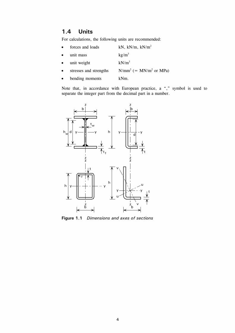
Dimensions and axes of sections are illustrated in Figure 1.1. Note that contrary to normal practice in many countries, the major axis of a section is normally y-y and the minor axis z-z, see Section 1.3.
Latin upper case letters
A Accidental action; Area C Fixed value; Factor E Modulus of elasticity; Effect of actions F Action; Force G Permanent action; Shear modulus I Second moment of area L Length; Span; System length M Bending moment N Axial force Q Variable action R Resistance V Shear force W Section modulus
2
Greek upper case letters
Difference in ........ (precedes main symbol)
Latin lower case letters
a Distance between stiffeners; Throat thickness of a weld b Width; Breadth c Distance; Outstand d Diameter; Depth e Eccentricity; Shift of neutral axis; Edge distance; End distance f Strength (of a material) g Gap h Height i Radius of gyration; Integer k Coefficient; Factor l Buckling length m Constant n Number of ... p Pitch; Spacing q Distributed force r Radius; Root radius s Staggered pitch t Thickness uu Major axis vv Minor axis w Curling deformation xx, yy, zz Rectangular axes
Greek lower case letters
(alpha) Ratio; Factor (beta) Ratio; Factor (gamma) Partial factor
(epsilon) Strain; Coefficient
5,0
210000
235
yf
E
(lambda) Slenderness ratio (a bar above indicates non dimensional)
(rho) Reduction factor (sigma) Normal stress (tau) Shear stress (phi) Ratio (chi) Reduction factor (for buckling) (psi) Stress ratio; Reduction factor
Subscripts
a Average b Bearing; Buckling; Bolt c Cross section cr Critical
3
d Design E Euler; Internal force; Internal moment eff Effective e Effective (with further subscript) el Elastic f Flange g Gross i,j,k Indices (replace by numeral) k Characteristic LT Lateral-torsional M (Allowing for) bending moment N (Allowing for) axial force net Net o Initial pl Plastic R Resistance r Reduced value S Secant s Tensile stress (area); Stiffener t Tension; Tensile; Torsion u Major axis of cross-section; Ultimate V (Allowing for) shear force v Shear; Minor axis of cross-section w Web; Weld; Warping x Axis along member y Yield (proof value); Axis of cross-section (major axis except for
unsymmetric sections) z Axis of cross-section (minor axis except for unsymmetric sections) Normal stress Shear stress.
1.3 Conventions for member axes In general, the convention for member axes is:
xx along the length of the member.
yy cross-section axis perpendicular to web, or the larger leg in the case of angle sections.
zz cross-section axis parallel to web, or the larger leg in the case of angle sections.
The yy axis will normally be the major axis of the section and the zz axis will normally be the minor axis. For angle sections, the major and minor axes (uu and vv) are inclined to the yy and zz axes, see Figure 1.1.
The convention used for subscripts which indicate axes for moments is: “Use the axis about which the moment acts”.
For example, for an I-section a bending moment acting in the plane of the web is denoted My because it acts about the cross-section axis perpendicular to the web.
4
1.4 Units For calculations, the following units are recommended:
forces and loads kN, kN/m, kN/m2
unit mass kg/m3
unit weight kN/m3
stresses and strengths N/mm2 (= MN/m2 or MPa)
bending moments kNm.
Note that, in accordance with European practice, a “,” symbol is used to separate the integer part from the decimal part in a number.
w y y y
tw
d
t f
h
t
dy
z z
zzb b
zz
y
r
yh y
bz z
t
h
y
v
u
u
vb
h
t
Figure 1.1 Dimensions and axes of sections
5
2 BASIS OF DESIGN
2.1 General requirements A structure should be designed and fabricated so that it can:
remain fit for use during its intended life
sustain the loads which may occur during construction, installation and usage
localise damage due to accidental overloads
have adequate durability in relation to maintenance costs.
The above requirements can be satisfied by using suitable materials, by appropriate design and detailing and by specifying quality control procedures for construction and maintenance.
Structures should be designed by considering all relevant limit states.
2.2 Limit state design Limit states are limiting conditions which, when exceeded, make the structure unable to meet design performance criteria. Three classes of limit states are recognised: ultimate limit states, serviceability limit states and durability limit states. Ultimate limit states are those which, if exceeded, can lead to collapse of part or the whole of the structure, endangering the safety of people. Serviceability limit states correspond to states beyond which specified service criteria are no longer met. Durability limit states can be regarded as subsets of the ultimate and serviceability limit states depending on whether, for example, the corrosion affects the strength of the structure or its aesthetic appearance. Examples of these limit states are given below:
Ultimate Limit State
Strength (including general yielding, rupture, buckling and transformation into a mechanism)
Stability against over-turning and sway
Fracture due to fatigue
Serviceability Limit State
Deflection
Vibration (e.g. wind induced)
Repairable damage due to fatigue
Creep
Durability Limit State
Corrosion
Metallurgical stability
6
Ultimate limit states
For ultimate limit states, relationships of the following form have to be satisfied:
Ed Rd (2.1)
where:
Ed is the design value of the effect of actions such as an internal moment or vector in the member or element under consideration due to the factored applied loading (see Section 2.3) acting on the structure, and
Rd is the corresponding design resistance, as given in the appropriate clause in these recommendations.
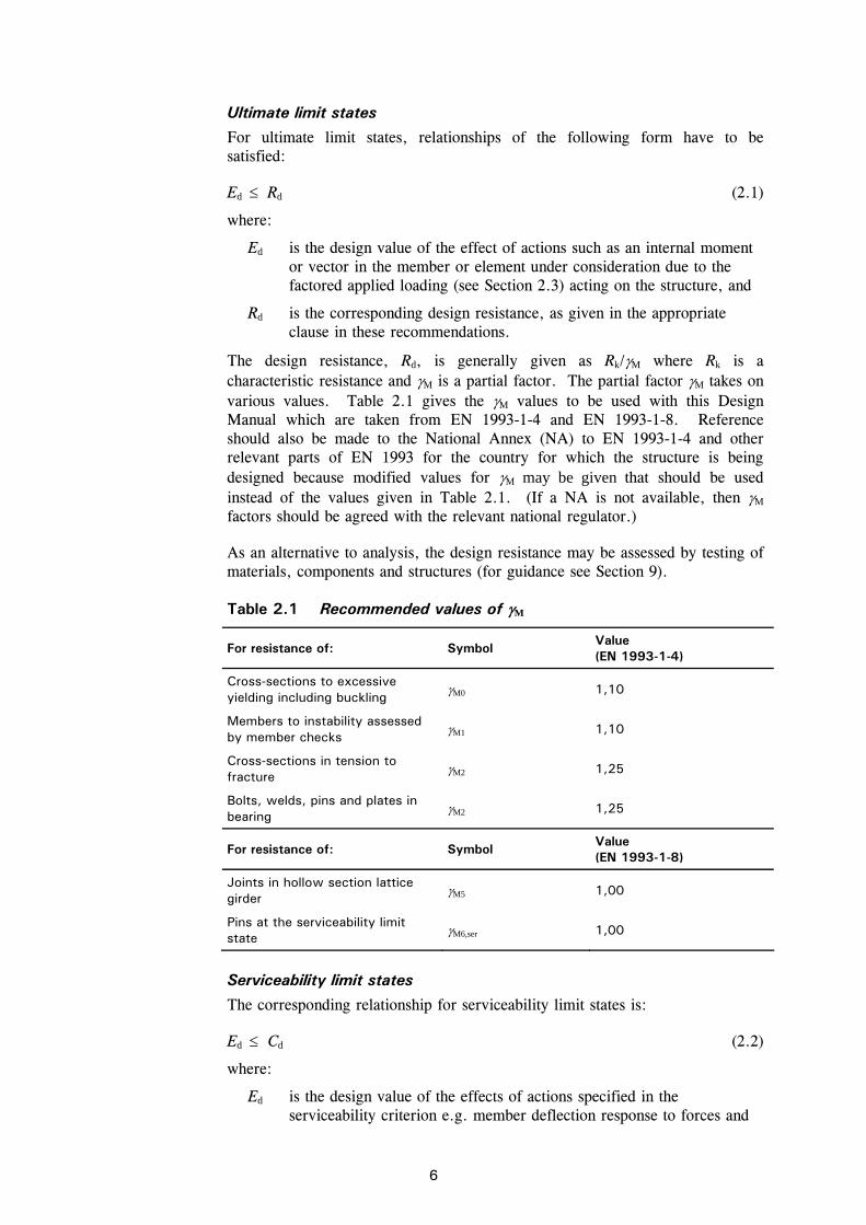
The design resistance, Rd, is generally given as Rk/M where Rk is a characteristic resistance and M is a partial factor. The partial factor M takes on various values. Table 2.1 gives the M values to be used with this Design Manual which are taken from EN 1993-1-4 and EN 1993-1-8. Reference should also be made to the National Annex (NA) to EN 1993-1-4 and other relevant parts of EN 1993 for the country for which the structure is being designed because modified values for M may be given that should be used instead of the values given in Table 2.1. (If a NA is not available, then M factors should be agreed with the relevant national regulator.)
As an alternative to analysis, the design resistance may be assessed by testing of materials, components and structures (for guidance see Section 9).
Table 2.1 Recommended values of M
For resistance of: Symbol Value (EN 1993-1-4)
Cross-sections to excessive yielding including buckling
M0 1,10
Members to instability assessed by member checks
M1 1,10
Cross-sections in tension to fracture
M2 1,25
Bolts, welds, pins and plates in bearing
M2 1,25
For resistance of: Symbol Value (EN 1993-1-8)
Joints in hollow section lattice girder
M5 1,00
Pins at the serviceability limit state
M6,ser 1,00
Serviceability limit states
The corresponding relationship for serviceability limit states is:
Ed Cd (2.2)
where:
Ed is the design value of the effects of actions specified in the serviceability criterion e.g. member deflection response to forces and
7
moments in the member due to the unfactored applied loading (Fk, see Section 2.3.4), and
Cd is the limiting design value of the relevant serviceability criterion.
Durability limit states
These states require consideration of the corrosion phenomena addressed in Section 3.7.
2.3 Loading 2.3.1 General In the Eurocodes, loading is expressed terms of ‘actions’. An ‘action’ is defined as:
A set of forces (loads) applied to the structure (direct action)
A set of imposed deformations or accelerations caused by, for example temperature changes, moisture variation, uneven settlement or earthquakes (indirect action).
Characteristic values (Fk) of individual actions are specified:
in EN 1991 Actions on structures (taking into account possible additions and/or changes in the relevant National Annex) or other relevant loading code, or
by the client, or the designer in consultation with the client, provided that the minimum provisions specified in the relevant loading codes or by a competent authority are observed.
The design values of individual actions (Fd) are given by multiplying characteristic actions by partial factors for actions (
F).
The design case is established by considering all realistic combinations of actions and identifying the critical case.
2.3.2 Ultimate limit state - Onshore factored loads The following types of action are recognised:
“Permanent” actions (G) - e.g. self-weight of structures, fittings, ancillaries and fixed equipment.
“Variable” actions (Q) - e.g. imposed loads, wind loads, snow loads, and thermal loads.
“Accidental” actions (A) - e.g. explosions, fire and vehicle impact.
EN 1990 Basis of Structural Design gives combinations of actions for use in design of buildings and recommended values for partial factors for actions (
F).
Reference should also be made to the National Annex to EN 1990 for the country for which the structure is being designed because it may give modified values for
F that should be used instead of the recommended values. The NA
also gives recommended values for the combination factors ( factors) and the unfavourable permanent actions (ξ factors). (If a NA is not available, then
F,
and ξ factors should be agreed with the relevant national regulator.)
8
Reference should be made to the National Annex of EN 1991 regarding numerical values for loads.
As given in EN 1990, for normal usage, i.e. in situations not involving accidents, the combination of actions may be expressed as:
1
jk,jG,j
G + k,1Q,1 Q + 1
ik,,0iQ,i
iQ (2.3)
or alternatively, the less favourable of the following expressions
1
jk,jG,j
G + Q,1 0,1 k,1Q + 1
ik,i,0iQ,i
Q (2.4a)
1
jk,jG,jj
G + k,1Q,1 Q + 1
ik,i,0iQ,i
Q (2.4b)
where:
Gk,j is the characteristic value of the permanent action
Qk,1 is the characteristic value of leading variable action 1 (i.e. the most unfavourable variable action)
Qk,i are the characteristic values of the accompanying variable actions i
j is the index for permanent action
i is the index for variable action
G,j is the partial factor for the permanent action Gk,j
Q,1 is the partial factor for the leading variable action 1
ξj is a reduction factor for unfavourable permanent actions G
ψ0,i is a reduction factor for combination value of a variable action Q.
However, reference again should be made to the NA for the particular country for which the structure is being designed.
The following recommended values are given in EN 1990:
G,j = 1,35 (for unfavourable effects)
Q,1 = 1,5 Q,i = 1,5
ξ = 0,85
The value of ψ 0 depends on the type of loading (see EN 1990).
Equations 2.4a and 2.4b were introduced because Equation 2.3 was unduly pessimistic for heavyweight structures. For steel structures, Equations 2.4a and 2.4b generally result in lighter loads than Equation 2.3.
2.3.3 Ultimate limit state - Offshore factored loads Reference may be made to API RP2A - LRFD Recommended Practice for Planning, Designing and Constructing Fixed Offshore Platforms - Load and Resistance Factor Design, First Edition, 1993.
The following factored load combinations from AP1 RP2A for the in-place condition are suggested for use in this Design Manual in conjunction with the
9
loads specified in API RP2A for the design of topside stainless steel components. Note that the notation is as used in API RP2A.
Operating conditions:
1,3D1 + 1,3D2 + 1,5L1 + 1,5L2 + 1,2(Wo + 1,25Dn) (2.5)
Extreme storm conditions:
1,1D1 + 1,1D2 + 1,1L1 + 1,35(We + 1,25Dn) (2.6)
When internal forces due to gravity loads oppose the internal forces due to wind, wave and current loads, the gravity loads should be reduced such that:
0,9D1 + 0,9D2 + 0,8L1 + 1,35(We + 1,25Dn) (2.7)
where:
D1 is the dead load, including self-weight of structures, fittings, ancillaries and permanent equipment
D2 is the dead load, including weight of equipment and other objects which may change from one mode of operation to another
L1 is Live load 1 (includes weight of consumable supplies in pipes and tanks)
L2 is Live load 2 (short duration forces arising from operations such as lifting of drill string, lifting by cranes, machine operations, vessel mooring and helicopter loadings)
Wo is the operator defined operating wind, wave and current load or effects
We are the extreme wind, wave and current load or effects (100 year return period)
Dn are the inertial forces.
2.3.4 Serviceability limit state loads Serviceability limit states should be checked for the following combinations:
characteristic
frequent
quasi-permanent load combinations.
EN 1990 gives combinations of actions for use in design of buildings. (Reference should also be made to the NA for the particular country for which the structure is being designed.) EN 1990 also requires that the acceptable deflection should be agreed with the client.
For the characteristic combination, normally used for irreversible limit states, the following load combination should be used:
1
ik,i,01k,1
jk,ij
QQG (2.8)
where all terms are defined in Section 2.3.2.
10
Note that EN 1990 gives the appropriate combinations of actions to use in the following situations:
for calculating deflections under normal combinations of actions (Clause A.1.4.3(1))
when long term deformations due to shrinkage, relaxation or creep need to be considered (Clause A.1.4.3(6))
if the appearance of the structure or the comfort of the user or functioning of machinery are being considered (Clauses A.1.4.3(4) and (5)).
11
3 MATERIALS: PROPERTIES, SELECTION AND DURABILITY
3.1 Material grades 3.1.1 Introduction There are many different types of stainless steel. Not all of these are suitable for structural applications, particularly where welding is contemplated. There are five basic groups of stainless steel, classified according to their metallurgical structure: these are the austenitic, ferritic, martensitic, duplex and precipitation-hardening groups. The austenitic stainless steels and the duplex stainless steels are generally the more useful groups for structural applications.
Austenitic stainless steels provide a good combination of corrosion resistance, forming and fabrication properties. Duplex stainless steels have high strength and wear resistance with very good resistance to stress corrosion cracking.
The most commonly used grades, typically referred to as the standard austenitic grades, are 1.4301 (widely known as 304) and 1.4401 (widely known as 316). They contain about 17-18% chromium and 8-11% nickel. Grade 1.4301 is suitable for rural, urban and light industrial sites whilst grade 1.4401 is a more highly alloyed grade and will perform well in marine and industrial sites.
The low carbon versions of these grades are 1.4307 (304L) and 1.4404 (316L). Grades 1.4301 and 1.4401 were formerly made with significantly higher carbon levels with implications for corrosion behaviour1. Either the ‘L’ grade, or a stabilised steel such as 1.4541 and 1.4571 would have been used where there was concern about corrosion performance in the as-welded condition.
Grade 1.4318 is a low carbon, high nitrogen stainless steel which work hardens very rapidly when cold worked. It has a long track record of satisfactory performance in the railcar industry and is equally suitable for automotive, aircraft and architectural applications. Grade 1.4318 has similar corrosion resistance to 1.4301 and is most suitable for applications requiring higher strength than 1.4301 where large volumes are required. It is procured directly from the mill; specifiers interested in using 1.4318 should check availability directly with the mill. Its price is likely to be slightly higher than 1.4301, depending on the amount required.
An increasing use of stainless steels for load bearing applications has led to a demand for ‘lean’ duplex grades in which the mechanical and corrosion properties of duplex grades are combined with a leanly alloyed chemical composition. In the forthcoming Parts 4 and 5 of EN 10088 (see Section 3.1.2), the newly developed duplex grade 1.4162 is included. Grade 1.4162 is suitable for many applications in the construction sector with a proof strength in
1 Carbon present in the steel reacts with chromium and precipitates chromium carbides on grain boundaries under certain thermal cycles, e.g. in the weld heat affected zones (HAZ). The local loss of chromium from the boundary region into the carbide particles allows preferential intercrystalline corrosion attack and the steel is said to be sensitized, or to suffer from weld decay (see Section 3.7.2).

12
the range of 450 – 530 N/mm2, a corrosion resistance between the austenitic grades 1.4301 and 1.4404 and a lean chemical composition.
Only the rolled versions, as opposed to the cast versions, are considered. Guidance on grade selection for particular applications is given in Section 3.6.
3.1.2 Relevant standards Flat and long products
The relevant standard is EN 10088, Stainless steels. It comprises three parts:
Part 1, Lists of stainless steels, gives the chemical compositions and reference data on some physical properties such as modulus of elasticity, E.
Part 2, Technical delivery conditions for sheet, plate and strip of corrosion resisting steels for general purposes, gives the technical properties and chemical compositions for the materials used in forming structural sections.
Part 3, Technical delivery conditions for semi-finished products, bars, rods, wire, sections and bright products of corrosion resisting steels for general purposes, gives the technical properties and chemical compositions for the materials used in long products.
Parts 4 (flat products) and 5 (long products) of EN 10088 are now in preparation to cover material for construction purposes. They are likely to be published in 2007.
The designation systems adopted in EN 10088 are the European steel number and a steel name.
For example, grade 304L has a steel number 1.4307, where:
1. 43 07 Denotes steel Denotes one group of
stainless steels Individual grade identification
The steel name system provides some understanding of the steel composition. The name of the steel number 1.4307 is X2CrNi18-9, where:
X 2 CrNi 18-9 Denotes high alloy steel
100 x % of carbon
Chemical symbols of main alloying elements
% of main alloying elements
Each stainless steel name has a unique corresponding steel number. Appendix A gives a table showing the designations for equivalent grades of stainless steel in various national and European standards.
Table 3.1 gives minimum specified mechanical properties of common stainless steels to EN 10088-2. The chemical compositions of these grades are given in Table 3.2.
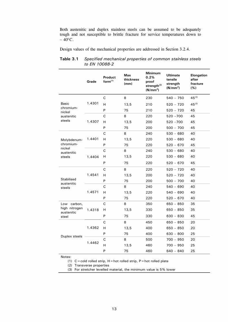
13
Both austenitic and duplex stainless steels can be assumed to be adequately tough and not susceptible to brittle fracture for service temperatures down to 40C.
Design values of the mechanical properties are addressed in Section 3.2.4.
Table 3.1 Specified mechanical properties of common stainless steels to EN 10088-2
Grade Product form(1)
Max thickness (mm)
Minimum 0.2% proof strength(2)
(N/mm2)
Ultimate tensile strength (N/mm2)
Elongation after fracture (%)
C 8 230 540 – 750 45(3)
H 13,5 210 520 – 720 45(3) 1.4301
P 75 210 520 – 720 45
C 8 220 520 –700 45
H 13,5 200 520 –700 45
Basic chromium-nickel austenitic steels 1.4307
P 75 200 500 – 700 45
C 8 240 530 – 680 40
H 13,5 220 530 – 680 40 1.4401
P 75 220 520 – 670 45
C 8 240 530 – 680 40
H 13,5 220 530 – 680 40
Molybdenum-chromium- nickel austenitic steels 1.4404
P 75 220 520 – 670 45
C 8 220 520 – 720 40
H 13,5 200 520 – 720 40 1.4541
P 75 200 500 – 700 40
C 8 240 540 – 690 40
H 13,5 220 540 – 690 40
Stabilised austenitic steels
1.4571
P 75 220 520 – 670 40
C 8 350 650 – 850 35
H 13,5 330 650 – 850 35
Low carbon, high nitrogen austenitic steel
1.4318
P 75 330 630 – 830 45
C 8 450 650 – 850 20
H 13,5 400 650 – 850 20 1.4362
P 75 400 630 – 800 25
C 8 500 700 – 950 20
H 13,5 460 700 – 950 25
Duplex steels
1.4462
P 75 460 640 – 840 25
Notes: (1) C=cold rolled strip, H=hot rolled strip, P=hot rolled plate (2) Transverse properties (3) For stretcher levelled material, the minimum value is 5% lower
14
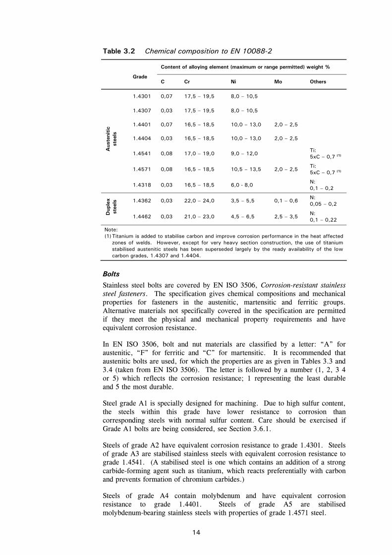
Table 3.2 Chemical composition to EN 10088-2
Content of alloying element (maximum or range permitted) weight %
Grade
C Cr Ni Mo Others
1.4301 0,07 17,5 – 19,5 8,0 – 10,5
1.4307 0,03 17,5 – 19,5 8,0 – 10,5
1.4401 0,07 16,5 – 18,5 10,0 – 13,0 2,0 – 2,5
1.4404 0,03 16,5 – 18,5 10,0 – 13,0 2,0 – 2,5
1.4541 0,08 17,0 – 19,0 9,0 – 12,0 Ti: 5xC – 0,7 (1)
1.4571 0,08 16,5 – 18,5 10,5 – 13,5 2,0 – 2,5 Ti: 5xC – 0,7 (1)
Aus
teni
tic
stee
ls
1.4318 0,03 16,5 – 18,5 6,0 - 8,0 N: 0,1 – 0,2
1.4362 0,03 22,0 – 24,0 3,5 – 5,5 0,1 – 0,6 N: 0,05 – 0,2
Dup
lex
stee
ls
1.4462 0,03 21,0 – 23,0 4,5 – 6,5 2,5 – 3,5 N: 0,1 – 0,22
Note: (1) Titanium is added to stabilise carbon and improve corrosion performance in the heat affected
zones of welds. However, except for very heavy section construction, the use of titanium stabilised austenitic steels has been superseded largely by the ready availability of the low carbon grades, 1.4307 and 1.4404.
Bolts
Stainless steel bolts are covered by EN ISO 3506, Corrosion-resistant stainless steel fasteners. The specification gives chemical compositions and mechanical properties for fasteners in the austenitic, martensitic and ferritic groups. Alternative materials not specifically covered in the specification are permitted if they meet the physical and mechanical property requirements and have equivalent corrosion resistance.
In EN ISO 3506, bolt and nut materials are classified by a letter: “A” for austenitic, “F” for ferritic and “C” for martensitic. It is recommended that austenitic bolts are used, for which the properties are as given in Tables 3.3 and 3.4 (taken from EN ISO 3506). The letter is followed by a number (1, 2, 3 4 or 5) which reflects the corrosion resistance; 1 representing the least durable and 5 the most durable.
Steel grade A1 is specially designed for machining. Due to high sulfur content, the steels within this grade have lower resistance to corrosion than corresponding steels with normal sulfur content. Care should be exercised if Grade A1 bolts are being considered, see Section 3.6.1.
Steels of grade A2 have equivalent corrosion resistance to grade 1.4301. Steels of grade A3 are stabilised stainless steels with equivalent corrosion resistance to grade 1.4541. (A stabilised steel is one which contains an addition of a strong carbide-forming agent such as titanium, which reacts preferentially with carbon and prevents formation of chromium carbides.)
Steels of grade A4 contain molybdenum and have equivalent corrosion resistance to grade 1.4401. Steels of grade A5 are stabilised molybdenum-bearing stainless steels with properties of grade 1.4571 steel.
15
Austenitic bolts can be obtained in three ultimate strength levels (known as property classes), see Table 3.3. Note that values must be agreed for bolts larger than M39 for property class 50 and M24 for property classes 70 and 80 as the values depend on the alloy and manufacturing method.
Bolts manufactured to property class 50 will be non-magnetic, but those to property classes 70 and 80 may demonstrate some magnetic properties.
The condition of the alloy in property class 50 bolts is soft, resulting in the highest corrosion resistance. Property classes 70 and 80 are cold worked and this can affect corrosion resistance slightly. Property class 50 bolts having machined threads may be more prone to thread galling, see Section 10.5.
Consideration should be given to matching the strength and corrosion resistance of the bolts and parent material.
EN 14399 gives rules for the CE marking of bolts.
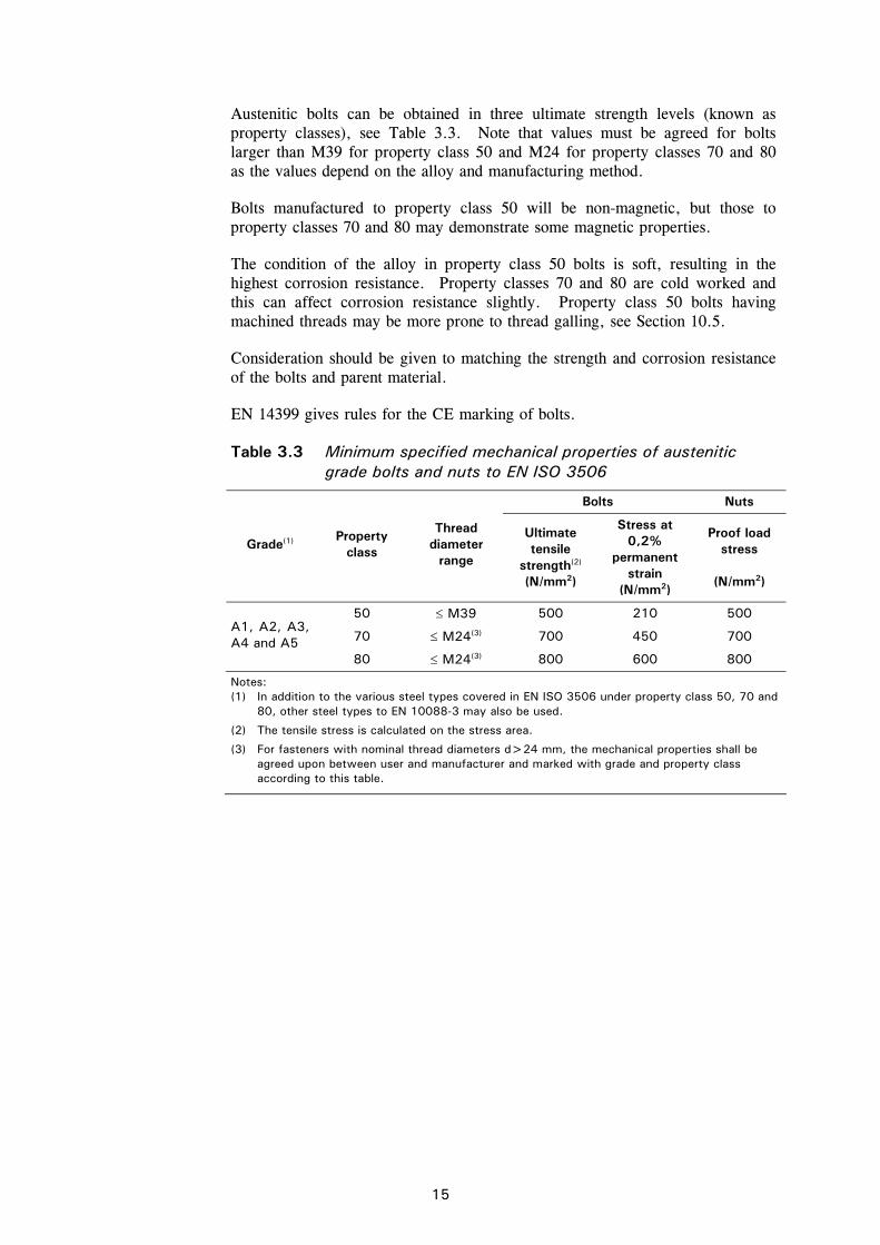
Table 3.3 Minimum specified mechanical properties of austenitic grade bolts and nuts to EN ISO 3506
Bolts Nuts
Grade(1) Property
class
Thread diameter
range
Ultimate tensile
strength(2) (N/mm2)
Stress at 0,2%
permanent strain
(N/mm2)
Proof load stress
(N/mm2)
50 M39 500 210 500
70 M24(3) 700 450 700 A1, A2, A3, A4 and A5
80 M24(3) 800 600 800
Notes: (1) In addition to the various steel types covered in EN ISO 3506 under property class 50, 70 and
80, other steel types to EN 10088-3 may also be used.
(2) The tensile stress is calculated on the stress area.
(3) For fasteners with nominal thread diameters d>24 mm, the mechanical properties shall be agreed upon between user and manufacturer and marked with grade and property class according to this table.
16
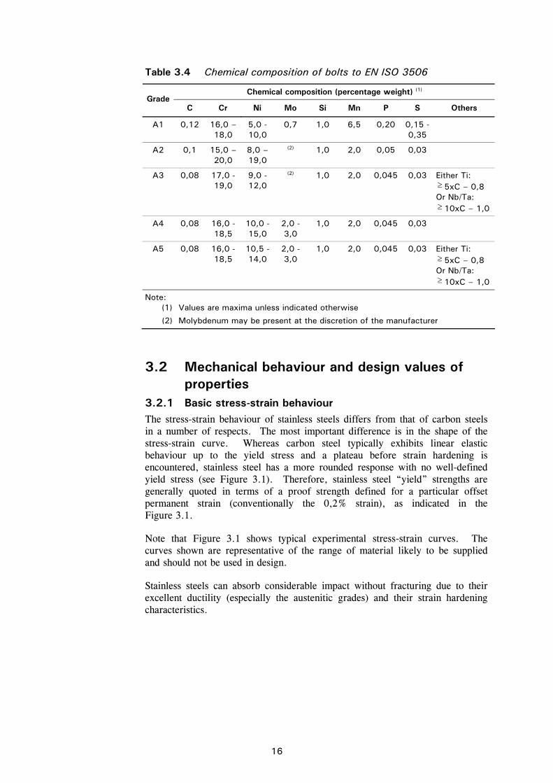
Table 3.4 Chemical composition of bolts to EN ISO 3506
Chemical composition (percentage weight) (1) Grade
C Cr Ni Mo Si Mn P S Others
A1 0,12 16,0 – 18,0
5,0 - 10,0
0,7 1,0 6,5 0,20 0,15 - 0,35
A2 0,1 15,0 – 20,0
8,0 – 19,0
(2) 1,0 2,0 0,05 0,03
A3 0,08 17,0 - 19,0
9,0 - 12,0
(2) 1,0 2,0 0,045 0,03 Either Ti: 5xC – 0,8 Or Nb/Ta: 10xC – 1,0
A4 0,08 16,0 - 18,5
10,0 - 15,0
2,0 - 3,0
1,0 2,0 0,045 0,03
A5 0,08 16,0 - 18,5
10,5 - 14,0
2,0 - 3,0
1,0 2,0 0,045 0,03 Either Ti: 5xC – 0,8 Or Nb/Ta: 10xC – 1,0
Note: (1) Values are maxima unless indicated otherwise
(2) Molybdenum may be present at the discretion of the manufacturer
3.2 Mechanical behaviour and design values of properties
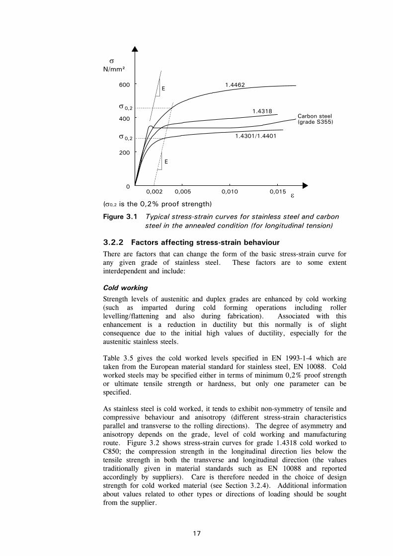
3.2.1 Basic stress-strain behaviour The stress-strain behaviour of stainless steels differs from that of carbon steels in a number of respects. The most important difference is in the shape of the stress-strain curve. Whereas carbon steel typically exhibits linear elastic behaviour up to the yield stress and a plateau before strain hardening is encountered, stainless steel has a more rounded response with no well-defined yield stress (see Figure 3.1). Therefore, stainless steel “yield” strengths are generally quoted in terms of a proof strength defined for a particular offset permanent strain (conventionally the 0,2% strain), as indicated in the Figure 3.1.
Note that Figure 3.1 shows typical experimental stress-strain curves. The curves shown are representative of the range of material likely to be supplied and should not be used in design.
Stainless steels can absorb considerable impact without fracturing due to their excellent ductility (especially the austenitic grades) and their strain hardening characteristics.
17
3.2.2 Factors affecting stress-strain behaviour There are factors that can change the form of the basic stress-strain curve for any given grade of stainless steel. These factors are to some extent interdependent and include:
Cold working
Strength levels of austenitic and duplex grades are enhanced by cold working (such as imparted during cold forming operations including roller levelling/flattening and also during fabrication). Associated with this enhancement is a reduction in ductility but this normally is of slight consequence due to the initial high values of ductility, especially for the austenitic stainless steels.
Table 3.5 gives the cold worked levels specified in EN 1993-1-4 which are taken from the European material standard for stainless steel, EN 10088. Cold worked steels may be specified either in terms of minimum 0,2% proof strength or ultimate tensile strength or hardness, but only one parameter can be specified.
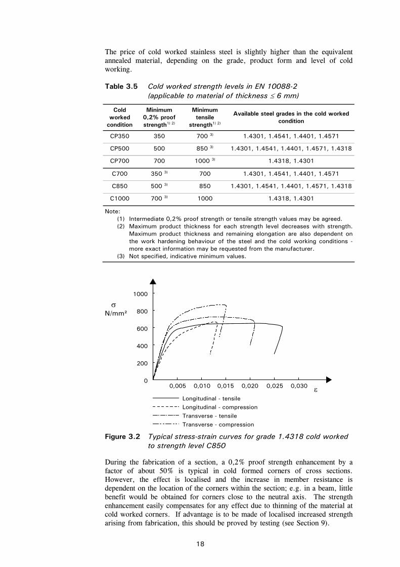
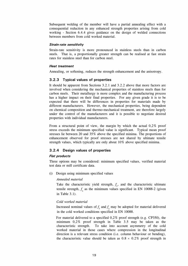
As stainless steel is cold worked, it tends to exhibit non-symmetry of tensile and compressive behaviour and anisotropy (different stress-strain characteristics parallel and transverse to the rolling directions). The degree of asymmetry and anisotropy depends on the grade, level of cold working and manufacturing route. Figure 3.2 shows stress-strain curves for grade 1.4318 cold worked to C850; the compression strength in the longitudinal direction lies below the tensile strength in both the transverse and longitudinal direction (the values traditionally given in material standards such as EN 10088 and reported accordingly by suppliers). Care is therefore needed in the choice of design strength for cold worked material (see Section 3.2.4). Additional information about values related to other types or directions of loading should be sought from the supplier.
600
200
0
0,2
0,2
0,005 0,010 0,015
E
E
0,002
N/mm²
4001.4318
1.4462
Carbon steel (grade S355)
1.4301/1.4401
(0,2 is the 0,2% proof strength)
Figure 3.1 Typical stress-strain curves for stainless steel and carbon steel in the annealed condition (for longitudinal tension)
18
The price of cold worked stainless steel is slightly higher than the equivalent annealed material, depending on the grade, product form and level of cold working.
Table 3.5 Cold worked strength levels in EN 10088-2 (applicable to material of thickness 6 mm)
Cold worked
condition
Minimum 0,2% proof strength1) 2)
Minimum tensile
strength1) 2)
Available steel grades in the cold worked condition
CP350 350 700 3) 1.4301, 1.4541, 1.4401, 1.4571
CP500 500 850 3) 1.4301, 1.4541, 1.4401, 1.4571, 1.4318
CP700 700 1000 3) 1.4318, 1.4301
C700 350 3) 700 1.4301, 1.4541, 1.4401, 1.4571
C850 500 3) 850 1.4301, 1.4541, 1.4401, 1.4571, 1.4318
C1000 700 3) 1000 1.4318, 1.4301
Note: (1) Intermediate 0,2% proof strength or tensile strength values may be agreed. (2) Maximum product thickness for each strength level decreases with strength.
Maximum product thickness and remaining elongation are also dependent on the work hardening behaviour of the steel and the cold working conditions - more exact information may be requested from the manufacturer.
(3) Not specified, indicative minimum values.
During the fabrication of a section, a 0,2% proof strength enhancement by a factor of about 50% is typical in cold formed corners of cross sections. However, the effect is localised and the increase in member resistance is dependent on the location of the corners within the section; e.g. in a beam, little benefit would be obtained for corners close to the neutral axis. The strength enhancement easily compensates for any effect due to thinning of the material at cold worked corners. If advantage is to be made of localised increased strength arising from fabrication, this should be proved by testing (see Section 9).
400
200
00,005
600
800
1000
0,010 0,015 0,020 0,025 0,030
Longitudinal - tensile
N/mm²
Longitudinal - compressionTransverse - tensileTransverse - compression
Figure 3.2 Typical stress-strain curves for grade 1.4318 cold worked to strength level C850
19
Subsequent welding of the member will have a partial annealing effect with a consequential reduction in any enhanced strength properties arising from cold working - Section 6.4.4 gives guidance on the design of welded connections between members from cold worked material.
Strain-rate sensitivity
Strain-rate sensitivity is more pronounced in stainless steels than in carbon steels. That is, a proportionally greater strength can be realised at fast strain rates for stainless steel than for carbon steel.
Heat treatment
Annealing, or softening, reduces the strength enhancement and the anisotropy.
3.2.3 Typical values of properties It should be apparent from Sections 3.2.1 and 3.2.2 above that more factors are involved when considering the mechanical properties of stainless steels than for carbon steels. Their metallurgy is more complex and the manufacturing process has a higher impact on their final properties. For any given grade it is to be expected that there will be differences in properties for materials made by different manufacturers. However, the mechanical properties, being dependent on chemical composition and thermo-mechanical treatment, are therefore largely under the control of the manufacturers and it is possible to negotiate desired properties with individual manufacturers.
From a structural point of view, the margin by which the actual 0,2% proof stress exceeds the minimum specified value is significant. Typical mean proof stresses lie between 20 and 35% above the specified minima. The proportions of enhancement observed for proof stresses are not shared by ultimate tensile strength values, which typically are only about 10% above specified minima.
3.2.4 Design values of properties Flat products
Three options may be considered: minimum specified values, verified material test data or mill certificate data.
(i) Design using minimum specified values
Annealed material Take the characteristic yield strength, fy, and the characteristic ultimate tensile strength, f
u as the minimum values specified in EN 10088-2 (given
in Table 3.1).
Cold worked material Increased nominal values of fy and f
u may be adopted for material delivered
in the cold worked conditions specified in EN 10088.
For material delivered to a specified 0,2% proof strength (e.g. CP350), the minimum 0,2% proof strength in Table 3.5 may be taken as the characteristic strength. To take into account asymmetry of the cold worked material in those cases where compression in the longitudinal direction is a relevant stress condition (i.e. column behaviour or bending), the characteristic value should be taken as 0.8 0.2% proof strength in
20
Table 3.5. A higher value may be used if supported by appropriate experimental data.
For material delivered to a specified tensile strength (e.g. C700), the minimum tensile strength in Table 3.5 may be taken as the characteristic strength; the minimum 0,2% proof strength should be obtained from the supplier.
Note 1: Rectangular hollow sections are available in material cold worked to intermediate strengths between CP350 and CP500 with the yield and ultimate tensile strength guaranteed by the producer (the yield strength being valid in tension and compression).
Note 2: The design rules in this Design Manual are applicable for material up to grade CP500 and C850. For higher cold worked strength levels, design should be by testing according to Section 9. An exception is members with Class 1, 2 and 3 cross-sections which are not subject to local or global instability, for which the cross-section resistance may be calculated according to Section 4.
(ii) Design using test data
This should only be considered as an option where tensile testing has been carried out on coupons cut from the plate or sheet from which the members are to be formed or fabricated. The designer should also be satisfied that the tests have been carried out to a recognised standard, e.g. EN 10002-1, and that the procedures adopted by the fabricator are such that the member will be actually made from the tested material and positioned correctly within the structure.
A value for the design strength can be derived from a statistical approach carried out in accordance with the recommendations in Annex D of EN 1990.
It is recommended that the characteristic ultimate tensile strength, fu, should still be based on the specified minimum value given in EN 10088-2.
(iii) Design using mill certificate data
Measured values of the 0,2% proof stress are given on the mill (or release) certificate. A value for the design strength can be derived from a statistical approach carried out in accordance with the recommendations in Annex D of EN 1990.
It is recommended that the characteristic ultimate tensile strength, fu, should still be based on the specified minimum value given in EN 10088-2.
A value of 200 000 N/mm2 is given by EN 10088-1 for Young’s modulus for all the standard austenitic and duplex grades typically used in structural applications. For estimating deflections, the secant modulus is more appropriate, see Section 5.4.6. For these grades, a value of 0,3 can be taken for Poisson’s ratio and 76 900 N/mm2 for the shear modulus, G.
Bolts
For calculating the resistance of a bolt under tension or shear or combined tension and shear, take the basic strength fub as:
21
fub = ub
where ub is the specified minimum ultimate tensile strength given in Table 3.3 for the appropriate property class.
When it is necessary to consider the long term resistance of a bolt, reference should be made to EN 1990 for the appropriate combination of actions at the Ultimate Limit State.
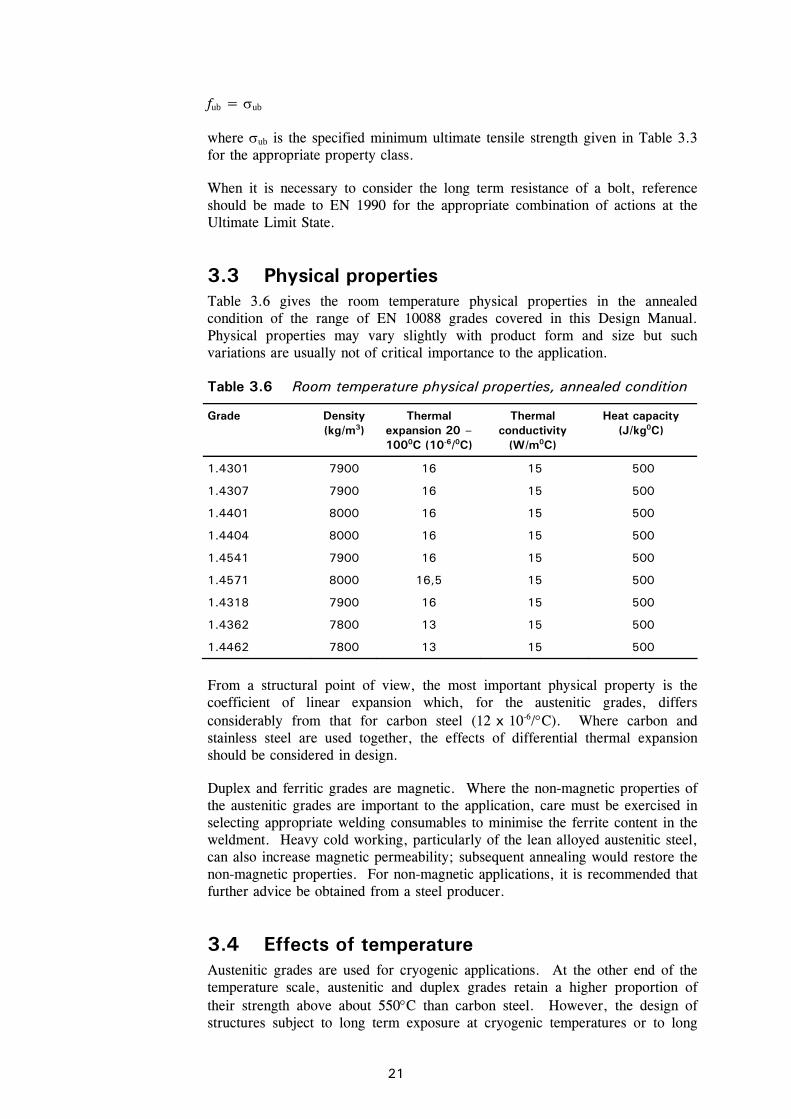
3.3 Physical properties Table 3.6 gives the room temperature physical properties in the annealed condition of the range of EN 10088 grades covered in this Design Manual. Physical properties may vary slightly with product form and size but such variations are usually not of critical importance to the application.
Table 3.6 Room temperature physical properties, annealed condition
Grade Density (kg/m3)
Thermal expansion 20 – 1000C (10-6/0C)
Thermal conductivity
(W/m0C)
Heat capacity (J/kg0C)
1.4301 7900 16 15 500
1.4307 7900 16 15 500
1.4401 8000 16 15 500
1.4404 8000 16 15 500
1.4541 7900 16 15 500
1.4571 8000 16,5 15 500
1.4318 7900 16 15 500
1.4362 7800 13 15 500
1.4462 7800 13 15 500
From a structural point of view, the most important physical property is the coefficient of linear expansion which, for the austenitic grades, differs considerably from that for carbon steel (12 x 10-6/C). Where carbon and stainless steel are used together, the effects of differential thermal expansion should be considered in design.
Duplex and ferritic grades are magnetic. Where the non-magnetic properties of the austenitic grades are important to the application, care must be exercised in selecting appropriate welding consumables to minimise the ferrite content in the weldment. Heavy cold working, particularly of the lean alloyed austenitic steel, can also increase magnetic permeability; subsequent annealing would restore the non-magnetic properties. For non-magnetic applications, it is recommended that further advice be obtained from a steel producer.
3.4 Effects of temperature Austenitic grades are used for cryogenic applications. At the other end of the temperature scale, austenitic and duplex grades retain a higher proportion of their strength above about 550C than carbon steel. However, the design of structures subject to long term exposure at cryogenic temperatures or to long
22
term exposure at high temperatures is outside the scope of this Design Manual. Suffice it to say that other mechanical properties and types of corrosion than those considered in this Section 3 take on a greater significance. Other stainless steels than those selected here are in most cases better suited for high temperature applications and further advice should be sought.
Duplex steels should not be used for long periods at temperatures above about 300C, due to the possibility of embrittlement.
Section 7 covers fire resistant design and gives mechanical and physical properties at high temperatures.
3.5 Life cycle costing There is increasing awareness that life cycle (or whole life) costs, not just initial costs, should be considered when selecting materials. Life cycle costs take account of:
initial costs,
operating costs,
residual value.
Stainless steel is sometimes considered to be an expensive material. However, experience has shown that using a corrosion resistant material in order to avoid future maintenance, downtime and replacement costs can save costs which far outweigh higher initial material costs.
The initial cost of a structural stainless steel product is considerably higher than that of an equivalent carbon steel product, depending on the grade of stainless steel. However, savings will arise from the omission of surface coatings at regular (repeated) intervals in time.
The excellent corrosion resistance of stainless steel can offer many benefits including:
reduced inspection frequency and costs,
reduced maintenance costs,
long service life.
Stainless steel has a high residual value (i.e. value at the end of a structure's life), though this is rarely a deciding factor for a structure with a long projected life (for instance over 50 years).
Life cycle costing uses the standard accountancy principle of discounted cash flow to reduce all those costs to present day values. The discount rate encompasses inflation, bank interest rates, taxes and, possibly, a risk factor. This allows a realistic comparison to be made of the options available and the potential long term benefits of using stainless steel to be assessed against other material selections.
23
3.6 Selection of materials 3.6.1 Grades In the great majority of structural applications utilising stainless steel, it is the metal's corrosion resistance, which is being exploited, whether this be for reasons of aesthetics, minimal maintenance or long-term durability. Corrosion resistance must therefore be the primary factor in choosing a suitable grade.
Stainless steels derive their corrosion resistance from the presence of a passive surface film which, given adequate access to oxygen or suitable oxidising agents, tends to be self-healing when damaged. This oxide film is primarily a consequence of the chromium content of the steel, though the addition of nickel and other alloying elements can substantially enhance the protection offered by the film. In particular, a small percentage of molybdenum is used to improve the pitting resistance of the steel (see Section 3.7.2).
It is when the surface oxide film is damaged, possibly by electro-chemical attack or by mechanical damage, that corrosion might initiate.
Careful design should ensure trouble-free performance, but designers should be aware that even stainless steels may be subject to various forms of corrosion under certain circumstances. Notwithstanding the existence of these degradation effects, it is perfectly possible to employ stainless steels extremely effectively, provided that a few elementary principles are kept in mind. It is only when these materials are used without consideration for the principles behind their corrosion properties that problems might be encountered.
The selection of the correct grade of stainless steel must take into account the environment of the application, the fabrication route, surface finish and the maintenance of the structure. It might be noted that the maintenance requirement is minimal: merely washing down the stainless steel, even naturally by rain, will markedly assist in extending the service life.
The first step is to characterise the service environment, including reasonably anticipated deviations from the design conditions. In categorising atmospheric environments, special attention should be given to highly localised conditions such as proximity to chimneys venting corrosive fumes. Possible future developments or change of use should also be considered. The surface condition and the temperature of the steel, and the anticipated stress, could also be important parameters (see Section 3.7.2).
Candidate grades can then be chosen to give overall satisfactory corrosion resistance in the environment. The selection of a candidate steel should consider which possible forms of corrosion might be significant in the operating environment. To do this requires some appreciation of the nature of corrosion found in stainless steels. Section 3.7 outlines the broad principles underlying the corrosion of stainless steels, and indicates conditions where use of stainless steels should be free of undue risk and complication. It is also intended to illustrate general points of good practice, as well as the circumstances where stainless steels might have to be used with caution. In these latter conditions specialist advice should be sought, for in many cases the steels can still be successfully used.
Consideration should then be given to mechanical properties, ease of fabrication, availability of product forms, surface finish and costs.
24
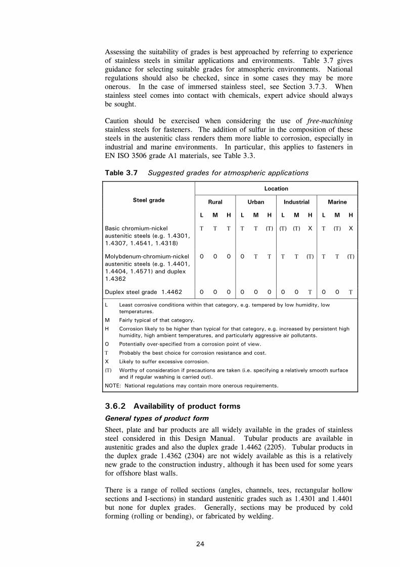
Assessing the suitability of grades is best approached by referring to experience of stainless steels in similar applications and environments. Table 3.7 gives guidance for selecting suitable grades for atmospheric environments. National regulations should also be checked, since in some cases they may be more onerous. In the case of immersed stainless steel, see Section 3.7.3. When stainless steel comes into contact with chemicals, expert advice should always be sought.
Caution should be exercised when considering the use of free-machining stainless steels for fasteners. The addition of sulfur in the composition of these steels in the austenitic class renders them more liable to corrosion, especially in industrial and marine environments. In particular, this applies to fasteners in EN ISO 3506 grade A1 materials, see Table 3.3.
Table 3.7 Suggested grades for atmospheric applications
Location
Rural Urban Industrial Marine Steel grade
L M H L M H L M H L M H
Basic chromium-nickel austenitic steels (e.g. 1.4301, 1.4307, 1.4541, 1.4318)
() () () X () X
Molybdenum-chromium-nickel austenitic steels (e.g. 1.4401, 1.4404, 1.4571) and duplex 1.4362
0 0 0 0 () ()
Duplex steel grade 1.4462 0 0 0 0 0 0 0 0 0 0
L Least corrosive conditions within that category, e.g. tempered by low humidity, low temperatures.
M Fairly typical of that category.
H Corrosion likely to be higher than typical for that category, e.g. increased by persistent high humidity, high ambient temperatures, and particularly aggressive air pollutants.
O Potentially over-specified from a corrosion point of view.
Probably the best choice for corrosion resistance and cost.
X Likely to suffer excessive corrosion.
() Worthy of consideration if precautions are taken (i.e. specifying a relatively smooth surface and if regular washing is carried out).
NOTE: National regulations may contain more onerous requirements.
3.6.2 Availability of product forms General types of product form
Sheet, plate and bar products are all widely available in the grades of stainless steel considered in this Design Manual. Tubular products are available in austenitic grades and also the duplex grade 1.4462 (2205). Tubular products in the duplex grade 1.4362 (2304) are not widely available as this is a relatively new grade to the construction industry, although it has been used for some years for offshore blast walls.
There is a range of rolled sections (angles, channels, tees, rectangular hollow sections and I-sections) in standard austenitic grades such as 1.4301 and 1.4401 but none for duplex grades. Generally, sections may be produced by cold forming (rolling or bending), or fabricated by welding.
25
Material in the cold worked condition is available in various product forms including plate, sheet, coil, strip, bars and hollow sections:
plate, sheet, coil, strip (in thicknesses typically 6.0 mm)
round bar (diameters from 5 mm to 60 mm)
square and rectangular hollow sections (cross-section dimensions up to 400 mm, thicknesses from 1.2 to 6 mm).
The grades of stainless steel which are commercially available in the cold worked condition are given in Table 3.5.
Cold forming
It is important that early discussion with potential fabricators takes place to ascertain cold forming limits as stainless steels require higher forming loads than carbon steels. The length of brake-pressed cold formed sections is necessarily limited by the size of machine or by power capability in the case of thicker or stronger materials. Duplex grades require approximately twice the forming loads used for the austenitic materials and consequently the possible range of duplex sections is more limited. Furthermore, because of the lower ductility in the duplex material, more generous bending radii should be used. Further information may be found in Section 10.3.2.
Surface finish
In certain applications, surface finish and appearance are important. Manufacturers offer a range of standard finishes, from mill finish through dull finishes to bright polish. They may also offer proprietary textured finishes. It should be noted that although the various finishes are standardised, variability in processing introduces differences in appearance between manufacturers and even from a single producer. Bright finishes are frequently used in architectural applications and it should be noted that bright finishes will exaggerate any out-of-flatness of the material, particularly on panel surfaces. Rigidised, embossed, textured, patterned or profiled sheets with a rigid supporting frame will alleviate this tendency.
Bolts
Bolts to EN ISO 3506 property class 70 are the most widely available. Certain size and length restrictions apply to bolts in property classes 70 and 80, see Table 3.3. It is possible to have “specials” made to order and indeed, this sometimes produces an economical solution.
Bolts can be produced by a number of techniques, e.g. machining, cold forming and forging. Machined threads should not be used in very aggressive environments (e.g. marine), due to potential problems with crevice corrosion. Rolled threads are also to be preferred because they are generally stronger than machined threads and provide greater resistance to thread galling.
3.7 Durability 3.7.1 Introduction Stainless steels are generally very corrosion resistant and will perform satisfactorily in most environments. The limit of corrosion resistance of a given stainless steel depends on its constituent elements, which means that each grade has a slightly different response when exposed to a corrosive environment.
26
Care is therefore needed to select the most appropriate grade of stainless steel for a given application. Generally, the higher the level of corrosion resistance required, the greater the cost of the material. For example, grade 1.4401 steel costs more than grade 1.4301 because of the addition of molybdenum.
Material in the cold worked condition has a similar corrosion resistance to that in the annealed condition.
The most common reasons for a metal to fail to live up to expectations regarding corrosion resistance are:
(a) incorrect assessment of the environment or exposure to unexpected conditions, e.g. unsuspected contamination by chloride ions
(b) the way in which the stainless steel has been worked or treated may introduce a state not envisaged in the initial assessment.
Although stainless steel may be subject to discolouration and staining (often due to carbon steel contamination), it is extremely durable in buildings. In aggressive industrial and marine environments, tests have shown no indication of reduction in component capacity even where a small amount of weight loss occurred. However, the user may still regard unsightly rust staining on external surfaces as a failure. As well as careful material grade selection, good detailing and workmanship can significantly reduce the likelihood of staining and corrosion; practical guidance is given in Section 10. Experience indicates that any serious corrosion problem is most likely to show up in the first two or three years of service.
In certain aggressive environments, some grades of stainless steel will be susceptible to localised attack. Six mechanisms are described below although the last three are very rarely encountered in buildings onshore.
It should be emphasised that the presence of moisture (including that due to condensation) is necessary for corrosion to occur.
3.7.2 Types of corrosion and performance of steel grades Pitting corrosion
As the name implies, pitting takes the form of localised pits. It occurs as a result of local breakdown of the passive layer, normally by chloride ions although the other halides and other anions can have a similar effect. In a developing pit, corrosion products may create a very corrosive solution, often leading to high corrosion rates. In most structural applications, the extent of pitting is likely to be superficial and the reduction in section of a component is negligible. However, corrosion products can stain architectural features. A less tolerant view of pitting should be adopted for services such as ducts, piping and containment structures.
Since the chloride ion is by far the most common cause of pitting, coastal and marine environments are rather aggressive. The probability of a certain medium causing pitting depends on, besides the chloride content, factors such as the temperature, acidity or alkalinity and the content of oxidising agents. The pitting resistance of a stainless steel is dependent on its chemical composition. Chromium, molybdenum and nitrogen all enhance the resistance to pitting.
An approximate measure of pitting resistance is given by the Pitting Index or Pitting Resistance Equivalent (PRE) defined as:

27
PRE = % wt Cr + 3,3(% wt Mo) + 30(% wt N) for austenitic grades
PRE = % wt Cr + 3,3(% wt Mo) + 16(% wt N) for duplex grades
The PRE of a stainless steel is a useful guide to its ranking with other stainless steels, but has no absolute significance.
Grade 1.4301 has the lowest PRE of the grades covered in this Design Manual and hence is the most unsuitable grade for architectural applications in marine environments except, perhaps, for internal structural components effectively shielded from sea spray and mist. Grade 1.4301 may also show unacceptable levels of pitting in severe industrial atmospheres and therefore grade 1.4401 or a duplex grade is to be preferred.
Crevice corrosion
Crevice corrosion occurs in the same environments as pitting corrosion. Corrosion initiates more easily in a crevice than on a free surface because the diffusion of oxidants necessary for maintaining the passive film is restricted. The severity of a crevice is very dependent on its geometry: the narrower and deeper the crevice, the more severe the corrosion conditions. It is only likely to be a problem in stagnant solutions where a build up of chlorides can occur.
Crevices may result from a metal to metal joint, a gasket, biofouling, deposits and surface damage such as deep scratches. Every effort should be made to eliminate crevices, but it is often not possible to eliminate them entirely.
As in pitting corrosion, the alloying elements chromium, molybdenum and nitrogen enhance the resistance to attack and thus the resistance to crevice corrosion increases from grade 1.4301 through 1.4401 to 1.4462.
Bimetallic (galvanic) corrosion
When two dissimilar metals are in electrical contact and are also bridged by an electrolyte (i.e. an electrically conducting liquid such as sea water or impure fresh water), a current flows from the anodic metal to the cathodic or nobler metal through the electrolyte. As a result the less noble metal corrodes.
This form of corrosion is particularly relevant when considering joining stainless steel and carbon or low alloy steels. It is important to select welding consumables that are at least as noble as the parent material. In corrosive environments where water may be present such as heavy industrial environments, marine atmospheres, and where immersion in brackish or sea water may occur, martensitic and ferritic bolts (see Section 3.1.2) should be avoided for joining austenitic stainless steels.
Bimetallic corrosion need not be a problem with stainless steels, though sometimes its prevention can require precautions which at first sight might seem surprising. The prevention of bimetallic corrosion, in principle, is to prevent current flow by:
insulating dissimilar metals, i.e. breaking the metallic path (see Section 6.1.1).
preventing electrolyte bridging, i.e. breaking the electrolytic path by paint or other coating. Where protection is sought by this means and it is impracticable to coat both metals, then it is preferable to coat the more
28
noble one (i.e. stainless steel in the case of a stainless/carbon steel connection).
The risk of a deep corrosion attack is greatest if the area of the more noble metal (i.e. stainless steel) is large compared with the area of the less noble metal (i.e. carbon steel). Special attention should be paid to the use of paints or other coatings on the carbon steel. If there are any small pores or pinholes in the coating, the small area of bare carbon steel will provide a very large cathode/anode area ratio, and severe pitting of the carbon steel may occur. This is, of course, likely to be most severe under immersed conditions. For this reason it is preferable to paint the stainless steel; any pores will lead to small area ratios.
Adverse area ratios are likely to occur with fasteners and at joints. Carbon steel bolts in stainless steel members should be avoided because the ratio of the area of the stainless steel to the carbon steel is large and the bolts will be subject to aggressive attack. Conversely, the rate of attack of a carbon steel member by a stainless steel bolt is much slower. It is usually helpful to draw on previous experience in similar sites because dissimilar metals can often be safely coupled under conditions of occasional condensation or dampness with no adverse effects, especially when the conductivity of the electrolyte is low.
The prediction of these effects is difficult because the corrosion rate is determined by a number of complex issues. The use of electrical potential tables ignores the presence of surface oxide films and the effects of area ratios and different solution (electrolyte) chemistry. Therefore, uninformed use of these tables may produce erroneous results. They should be used with care and only for initial assessment.
Stainless steels usually form the cathode in a bimetallic couple and therefore do not suffer corrosion. Contact between austenitic stainless steels and zinc or aluminium may result in some additional corrosion of the latter two metals. This is unlikely to be significant structurally, but the resulting white/grey powder may be deemed unsightly. The couple with copper should generally be avoided except under benign conditions.
The general behaviour of metals in bimetallic contact in rural, urban, industrial and coastal environments is fully documented in BS PD 6484 Commentary on corrosion at bimetallic contacts and its alleviation.
Stress corrosion cracking
The development of stress corrosion cracking (SCC) requires the simultaneous presence of tensile stresses and specific environmental factors unlikely to be encountered in normal building atmospheres. The stresses do not need to be very high in relation to the proof stress of the material and may be due to loading, residual effects from manufacturing processes such as welding or bending. Duplex stainless steels usually have superior resistance to stress corrosion cracking than the austenitic stainless steels covered in this Design Manual. Higher alloy austenitic stainless steels such as grades 1.4539, 1.4529, 1.4547 and 1.4565 (not covered in this Design Manual) have been developed for applications where SCC is a corrosion hazard.
Caution should be exercised when stainless steel members containing high residual stresses (e.g. due to cold working) are used in chloride rich environments (e.g. indoor swimming pools, marine, offshore). EN 1993-1-4
29
advises that for load-bearing members in atmospheres containing chlorides that cannot be cleaned regularly (e.g. in suspended ceilings above swimming pools), only grades 1.4529, 1.4547, 1.4565 should be used, unless the concentration of chloride ions in the pool water is (unusually) 250 mg/l, in which case grade 1.4539 is also suitable. Alternative grades which have been shown to have equivalent resistance to stress corrosion cracking in these atmospheres may also be used.
General (uniform) corrosion
Under normal conditions typically encountered in structural applications, stainless steels do not suffer from the general loss of section that is characteristic of rusting in non-alloyed irons and steels.
Stainless steel is resistant to many chemicals; indeed it is sometimes used for their containment. However, reference should be made to tables in manufacturers' literature, or the advice of a competent corrosion engineer should be sought, if the stainless steel is to come into contact with chemicals.
Intergranular corrosion (sensitisation) and weld decay
When austenitic stainless steels are subject to prolonged heating in the range 450C to 850C, the carbon in the steel diffuses to the grain boundaries and precipitates chromium carbide. This removes chromium from the solid solution and leaves a lower chromium content adjacent to the grain boundaries. Steel in this condition is termed sensitized. The grain boundaries become prone to preferential attack on subsequent exposure to a corrosive environment. This phenomenon is known as weld decay when it occurs in the heat affected zone of a weldment.
There are three ways to avoid intergranular corrosion:
use steel having a low carbon content
use steel stabilised with titanium or niobium, because these elements combine preferentially with carbon to form stable particles, thereby reducing the risk of forming chromium carbide
use heat treatment, however this method is rarely used in practice.
Grades of stainless steel with a low carbon content (0,03% maximum) up to 20 mm thick should not suffer from intergranular corrosion after arc welding.
3.7.3 Corrosion in selected environments Air
Atmospheric environments vary, as do their effect on stainless steels. Rural atmospheres, uncontaminated by industrial fumes or coastal salt, are very mild in terms of corrosivity, even in areas of high humidity. Industrial and marine atmospheres are considerably more severe. Table 3.7 should be referred to for guidance on selecting suitable types of stainless steel.
The most common causes of atmospheric corrosion are metallic iron particles, arising from fabrication operations either in the workshop or at site, and chlorides originating from the sea, industrial processes or from calcium chloride used to make cement. Some deposited particles, although inert, are able to absorb weak acid solutions of sulfur dioxide from the atmosphere which may locally break down the passive film.
30
General appearance of exposed stainless steel is affected by surface finish (the smoother the better) and whether or not regular washing down is carried out (either intentionally or by rain).
Sea water
Sea water, including brackish water, contains high levels of chloride and hence is very corrosive, particularly when the water current is low (under about 1.5 m/s). At low current flows, severe pitting of grades 1.4301 and 1.4401 can occur. Also, these grades can suffer attack at crevices, whether these result from design details or from fouling organisms such as barnacles.
Salt spray may cause as much attack as complete immersion because the chloride concentration is raised by the evaporation of water or because of salt crystal deposits.
The possibility of severe bimetallic corrosion must be considered if stainless steel is used with other metals in the presence of sea water.
Other waters
Austenitic stainless steels usually perform satisfactorily in distilled, tap and boiler waters. Where acidity is high, grade 1.4401 is to be preferred, otherwise 1.4301 will usually suffice. Grade 1.4401 is also suggested as being more suitable where there are minor amounts of chloride present to avoid possible pitting and crevice corrosion problems. River water needs special consideration; biological and microbiological activity can cause pitting in austenitic stainless steels within a comparatively short time.
The possibility of erosion-corrosion should be considered for waters containing abrasive particles.
Chemical environments
The range of application of stainless steel in chemical environments is wide and it is not appropriate here to cover this subject in detail. It should be noted, however, that in many applications steels other than those considered in this Design Manual may be more suitable. The advice of a specialist corrosion engineer should be sought.
Charts published by manufacturers showing results of corrosion tests in various chemicals require careful interpretation. Although giving a guide to the resistance of a particular grade, service conditions (temperatures, pressures, concentrations, etc.) vary and will generally differ from the test conditions. Also, the effect of impurities and the degree of aeration can have a marked effect on results.
Soils
External corrosion of buried stainless steel is dependent on soil chemistry and resistivity. Soils differ in their corrosiveness depending on moisture level, pH, aeration, presence of chemical contamination, microbiological activity and surface drainage. Stainless steels generally perform well in a variety of soils and especially well in soils with high resistivity, although some pitting has occurred in low resistivity, moist soils. The presence of aggressive chemical species such as chloride ions as well as types of bacteria and stray current (caused by local direct current electric transportation systems such as railways or tram systems) can cause localized corrosion. The development of stray

31
current can be suppressed with a proper electrical insulation of the pipe (coatings or wrappings) and/or cathodic protection.
For grade selection purposes, it is recommended to consider the corrosion resistance of buried stainless steel firstly in relation to the presence of chloride ions and secondly according to the soil resistivity and pH, assuming poorly drained soils in all cases. Table 3.8 recommends suitable grades for different soil conditions.
Table 3.8 Stainless steel grades for use in different soil conditions
Typical location Soil condition Grade of stainless steel
Cl < 500 ppm
Resistivity >1000 ohm.cm
Inland
pH > 4.5
1.4301 1.4404
Cl < 1500 ppm
Resistivity >1000 ohm.cm
Marine – non-tidal zone
pH > 4.5
1.4404
Cl < 6000 ppm
Resistivity >500 ohm.cm
Marine – tidal zone
pH > 4.5
1.4410 1.4547
Note: 1.4410 is a duplex grade and 1.4547 is a super-austenitic grade. These grades are not generally used in construction applications and fall outside the scope of this Design Manual.
Design for corrosion control
The most important step in preventing corrosion problems is selecting an appropriate grade of stainless steel with suitable fabrication procedures for the given environment. However, after specifying a particular steel, much can be achieved in realising the full potential of the steel's resistance by careful attention to detailing. Anti-corrosion actions should ideally be considered at the planning stage and during detailed design.
Table 3.9 gives a check list for consideration. Not all points would give the best detail from a structural strength point of view and neither are the points intended to be applied to all environments. In particular, in environments of low corrosivity or where regular maintenance is carried out, many would not be required. Figure 3.3 illustrates poor and good design features for durability.
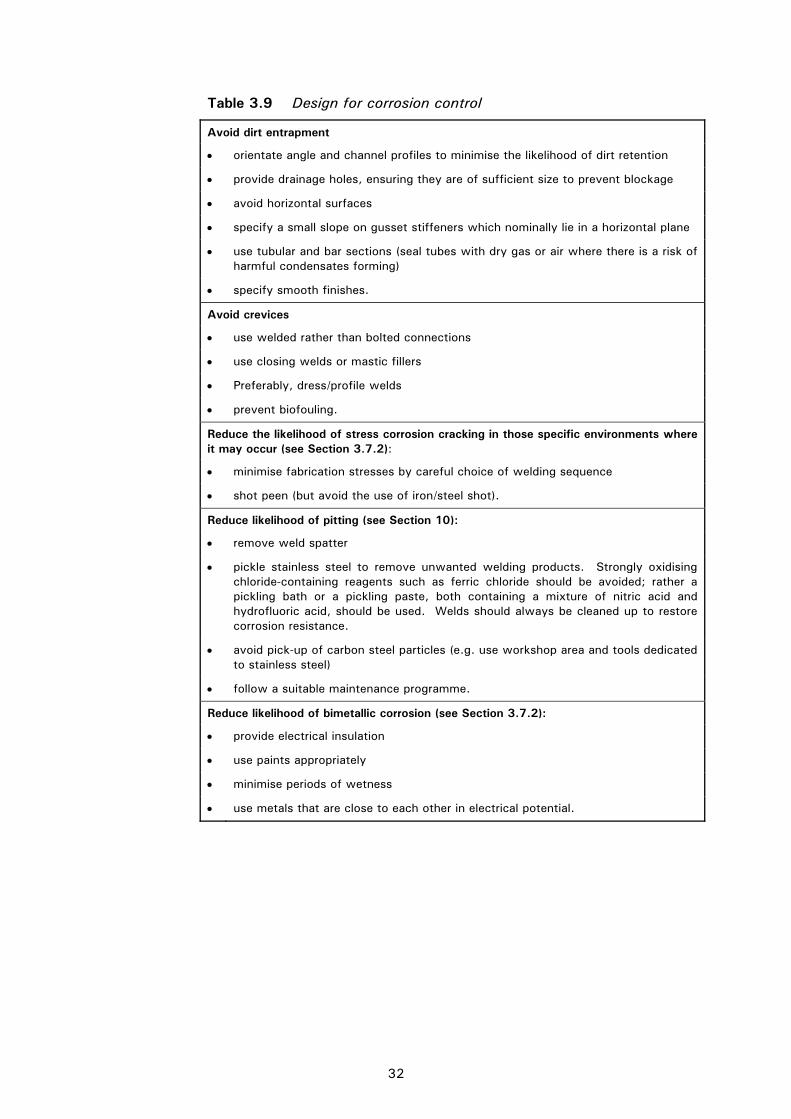
32
Table 3.9 Design for corrosion control
Avoid dirt entrapment
orientate angle and channel profiles to minimise the likelihood of dirt retention
provide drainage holes, ensuring they are of sufficient size to prevent blockage
avoid horizontal surfaces
specify a small slope on gusset stiffeners which nominally lie in a horizontal plane
use tubular and bar sections (seal tubes with dry gas or air where there is a risk of harmful condensates forming)
specify smooth finishes.
Avoid crevices
use welded rather than bolted connections
use closing welds or mastic fillers
Preferably, dress/profile welds
prevent biofouling.
Reduce the likelihood of stress corrosion cracking in those specific environments where it may occur (see Section 3.7.2):
minimise fabrication stresses by careful choice of welding sequence
shot peen (but avoid the use of iron/steel shot).
Reduce likelihood of pitting (see Section 10):
remove weld spatter
pickle stainless steel to remove unwanted welding products. Strongly oxidising chloride-containing reagents such as ferric chloride should be avoided; rather a pickling bath or a pickling paste, both containing a mixture of nitric acid and hydrofluoric acid, should be used. Welds should always be cleaned up to restore corrosion resistance.
avoid pick-up of carbon steel particles (e.g. use workshop area and tools dedicated to stainless steel)
follow a suitable maintenance programme.
Reduce likelihood of bimetallic corrosion (see Section 3.7.2):
provide electrical insulation
use paints appropriately
minimise periods of wetness
use metals that are close to each other in electrical potential.
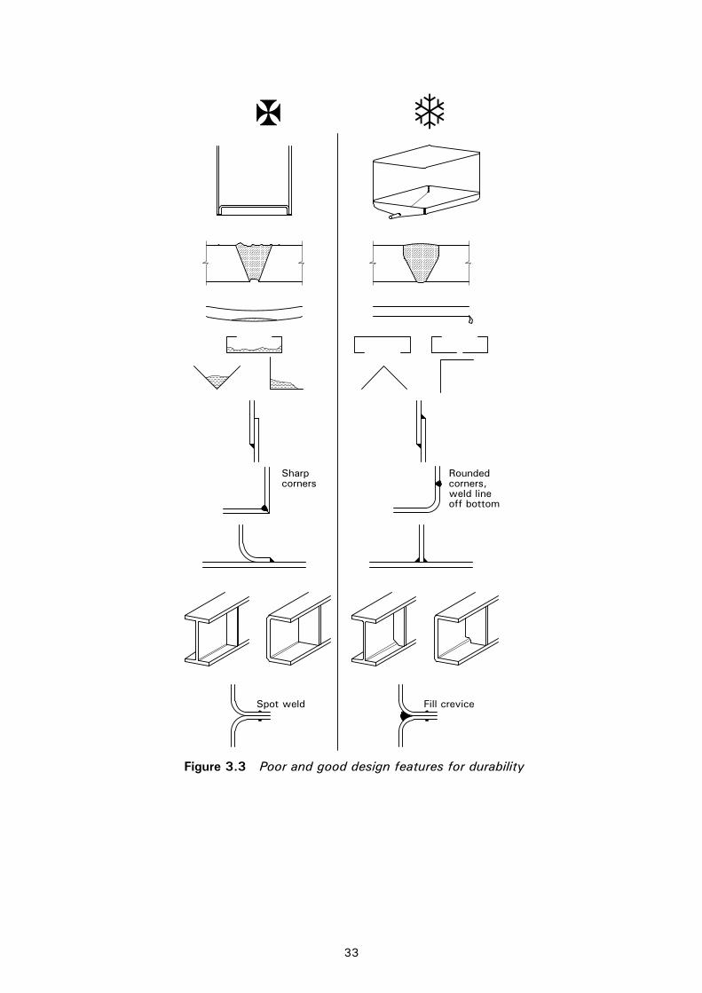
33
Spot weld Fill crevice
Sharpcorners
Roundedcorners,weld lineoff bottom
Figure 3.3 Poor and good design features for durability
34
4 PROPERTIES OF SECTIONS
4.1 General The recommendations in Sections 4 and 5 apply to cross-sections with elements complying with the dimensional limits of Section 4.2.
The width-to-thickness ratios of elements that are partly or wholly in compression determine whether they are subject to local buckling, with a consequential reduction in the resistance of the cross-section. Elements and cross-sections are classified as Class 1, 2, 3 or 4 depending on the susceptibility to local buckling and their rotation capacity (Class 1 and 2), see Section 4.3.
The reduced resistance of Class 4 cross-sections may be allowed for in design by the use of effective widths of elements, see Section 4.4.1.
Mid-line dimensions may only be used for calculating section properties of cold-formed members and sheeting. For other sections, the overall dimensions should be used. EN 1993-1-3 and EN 1993-1-5 permit mid-line dimensions to be used in calculating resistances. EN 1993-1-1 also allows the use of mid-line dimensions in calculating resistances in certain cases (see 6.2.1(9) but also 6.2.5(2) of EN 1993-1-1).
4.2 Maximum width-to-thickness ratios Table 4.1 gives maximum width-to-thickness ratios for stainless steel elements.
4.3 Classification of cross-sections 4.3.1 General In principle, stainless steel cross-sections may be classified in the same way as those of carbon steel. Four classes of cross-section are defined as follows:
Class 1 cross-sections are those which can form a plastic hinge with the rotation capacity required from plastic analysis.
Class 2 cross-sections are those which can develop their plastic moment resistance, but have limited rotation capacity.
Class 3 cross-sections are those in which the calculated stress in the extreme compression fibre of the steel member can reach its yield strength, but local buckling is liable to prevent development of the plastic moment resistance.
Class 4 cross-sections are those in which local buckling will occur before the attainment of yield stress in one or more parts of the cross-section.
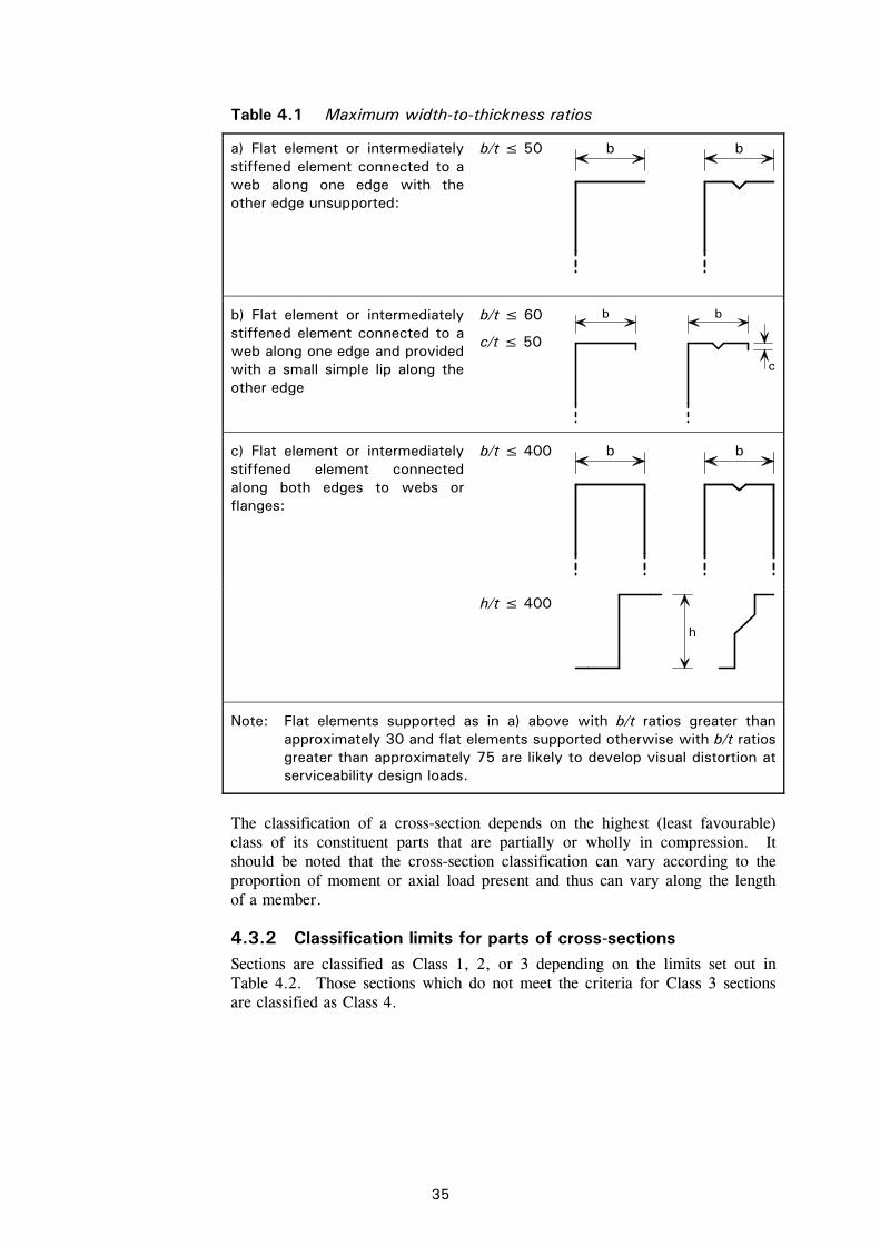
35
Table 4.1 Maximum width-to-thickness ratios
a) Flat element or intermediately stiffened element connected to a web along one edge with the other edge unsupported:
b/t ≤ 50
b b
b) Flat element or intermediately stiffened element connected to a web along one edge and provided with a small simple lip along the other edge
b/t ≤ 60
c/t ≤ 50
b b
c
c) Flat element or intermediately stiffened element connected along both edges to webs or flanges:
b/t ≤ 400
b b
h/t ≤ 400
h
Note: Flat elements supported as in a) above with b/t ratios greater than approximately 30 and flat elements supported otherwise with b/t ratios greater than approximately 75 are likely to develop visual distortion at serviceability design loads.
The classification of a cross-section depends on the highest (least favourable) class of its constituent parts that are partially or wholly in compression. It should be noted that the cross-section classification can vary according to the proportion of moment or axial load present and thus can vary along the length of a member.
4.3.2 Classification limits for parts of cross-sections Sections are classified as Class 1, 2, or 3 depending on the limits set out in Table 4.2. Those sections which do not meet the criteria for Class 3 sections are classified as Class 4.
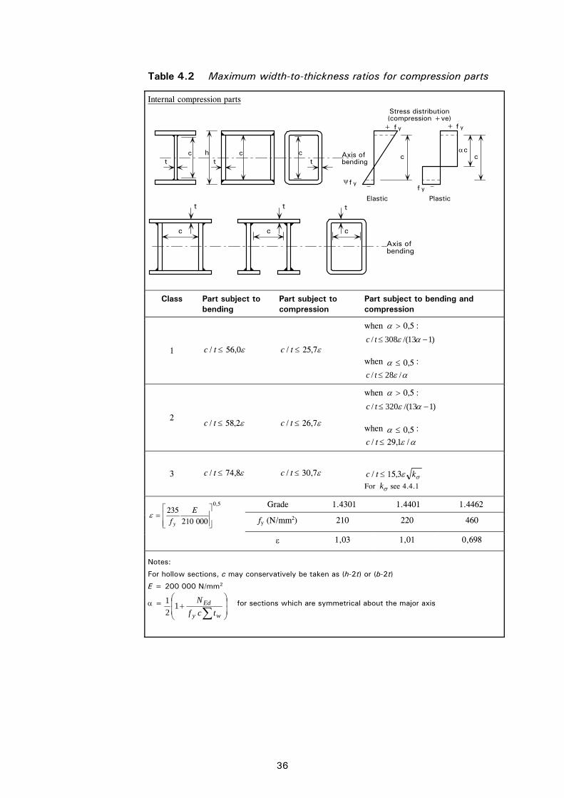
36
Table 4.2 Maximum width-to-thickness ratios for compression parts
Internal compression parts
Axis ofbending
+
––
Elastic Plastic
+
yf
yfyf
yf
Stress distribution(compression +ve)
h ct t t
c c ccc
Axis ofbending
t t
c c
t
c
Class Part subject to bending
Part subject to compression
Part subject to bending and compression
1 0,56/ tc 7,25/ tc
when 5,0 :
)113/(308/ tc
when 5,0 :
/28/ tc
2
2,58/ tc
7,26/ tc
when 5,0 :
)113/(320/ tc
when 5,0 :
/1,29/ tc
3 8,74/ tc 7,30/ tc
ktc 3,15/ For k see 4.4.1
Grade 1.4301 1.4401 1.4462
fy (N/mm2) 210 220 460
5,0
000210235
Ef y
1,03 1,01 0,698
Notes:
For hollow sections, c may conservatively be taken as (h-2t) or (b-2t)
E = 200 000 N/mm2
=
wy
Ed
tcf
N1
2
1 for sections which are symmetrical about the major axis
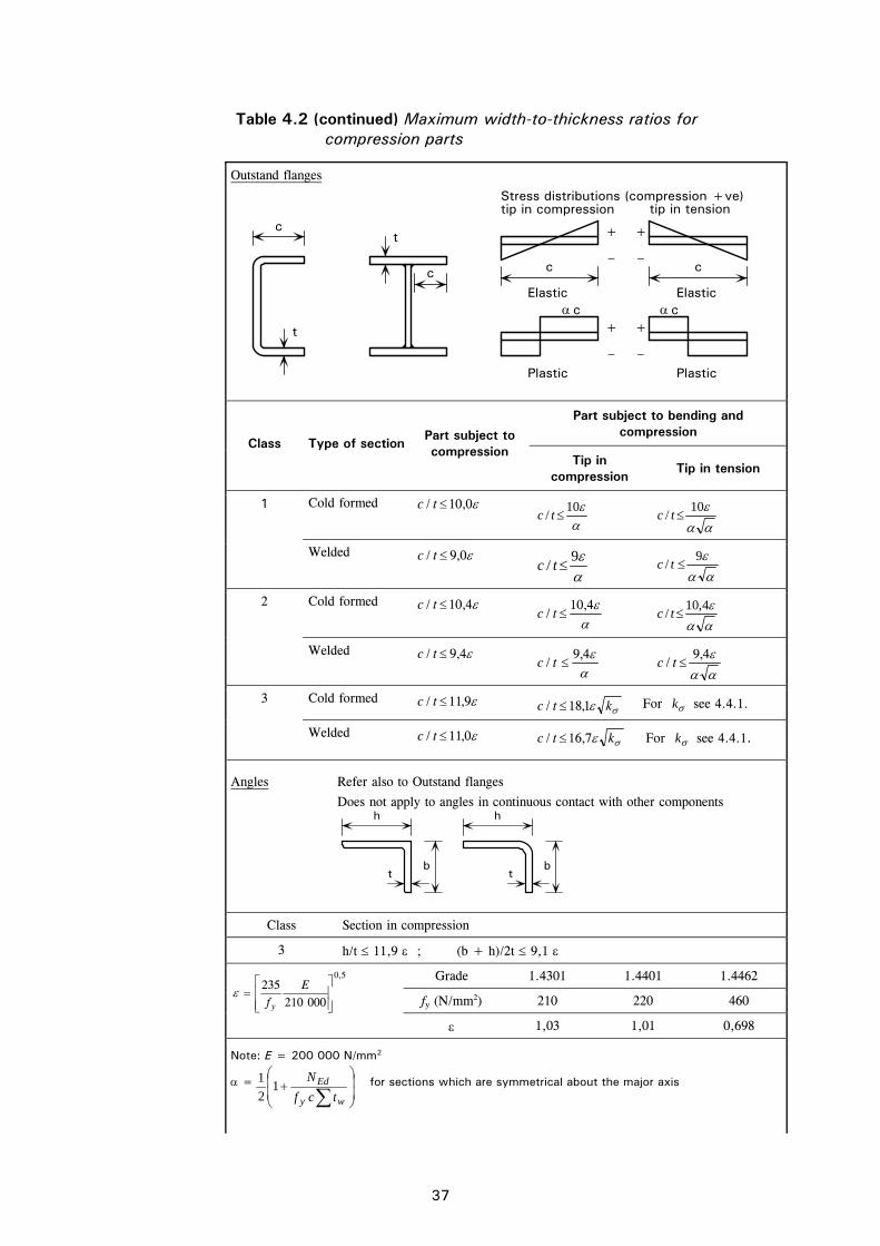
37
Table 4.2 (continued) Maximum width-to-thickness ratios for compression parts
Outstand flanges
+
–
+
–
cElastic
Plastic
+
–
+
–
cElastic
Plastic
tip in tensionStress distributions (compression +ve)tip in compression
c
c cc
t
t
Part subject to bending and compression
Class Type of section Part subject to compression
Tip in compression
Tip in tension
Cold formed 0,10/ tc
10
/ tc 10
/ tc 1
Welded 0,9/ tc
9
/ tc 9
/ tc
Cold formed 4,10/ tc
4,10
/ tc 4,10
/ tc 2
Welded 4,9/ tc
4,9
/ tc 4,9
/ tc
Cold formed 9,11/ tc ktc 1,18/ For k see 4.4.1. 3
Welded 0,11/ tc ktc 7,16/ For k see 4.4.1.
Angles Refer also to Outstand flanges
Does not apply to angles in continuous contact with other components
h
b
h
bt t
Class Section in compression
3 h/t 11,9 ; (b + h)/2t 9,1
Grade 1.4301 1.4401 1.4462
fy (N/mm2) 210 220 460
5,0
000210235
Ef y
1,03 1,01 0,698
Note: E = 200 000 N/mm2
=
wy
Ed
tcf
N1
2
1 for sections which are symmetrical about the major axis
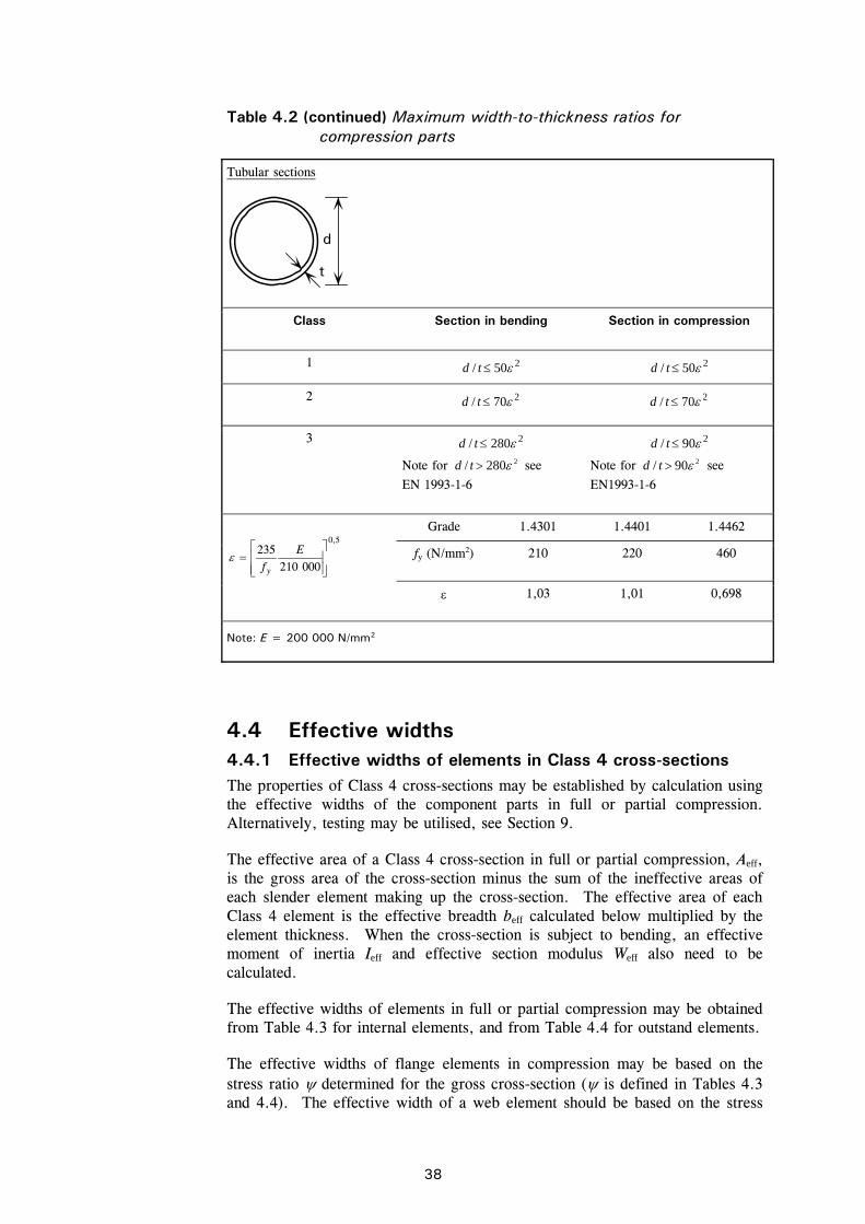
38
Table 4.2 (continued) Maximum width-to-thickness ratios for compression parts
Tubular sections
d
t
Class Section in bending Section in compression
1 250/ td 250/ td
2 270/ td 270/ td
3 2280/ td
Note for 2280/ td see
EN 1993-1-6
290/ td
Note for 290/ td see
EN1993-1-6
Grade 1.4301 1.4401 1.4462
fy (N/mm2) 210 220 460 5,0
000210235
Ef y
1,03 1,01 0,698
Note: E = 200 000 N/mm2
4.4 Effective widths 4.4.1 Effective widths of elements in Class 4 cross-sections The properties of Class 4 cross-sections may be established by calculation using the effective widths of the component parts in full or partial compression. Alternatively, testing may be utilised, see Section 9.
The effective area of a Class 4 cross-section in full or partial compression, Aeff, is the gross area of the cross-section minus the sum of the ineffective areas of each slender element making up the cross-section. The effective area of each Class 4 element is the effective breadth beff calculated below multiplied by the element thickness. When the cross-section is subject to bending, an effective moment of inertia Ieff and effective section modulus Weff also need to be calculated.
The effective widths of elements in full or partial compression may be obtained from Table 4.3 for internal elements, and from Table 4.4 for outstand elements.
The effective widths of flange elements in compression may be based on the stress ratio determined for the gross cross-section ( is defined in Tables 4.3 and 4.4). The effective width of a web element should be based on the stress
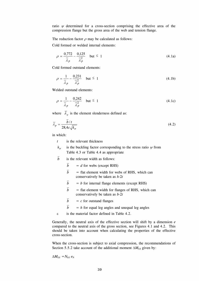
39
ratio determined for a cross-section comprising the effective area of the compression flange but the gross area of the web and tension flange.
The reduction factor may be calculated as follows:
Cold formed or welded internal elements:
2125,0772,0
pp but 1 (4.1a)
Cold formed outstand elements:
2231,01
pp but 1 (4.1b)
Welded outstand elements:
2242,01
pp but 1 (4.1c)
where p is the element slenderness defined as:
k
tbp
4,28
/ (4.2)
in which:
t is the relevant thickness
k is the buckling factor corresponding to the stress ratio from Table 4.3 or Table 4.4 as appropriate
b is the relevant width as follows:
b = d for webs (except RHS)
b = flat element width for webs of RHS, which can conservatively be taken as h-2t
b = b for internal flange elements (except RHS)
b = flat element width for flanges of RHS, which can conservatively be taken as b-2t
b = c for outstand flanges
b = h for equal leg angles and unequal leg angles
is the material factor defined in Table 4.2.
Generally, the neutral axis of the effective section will shift by a dimension e compared to the neutral axis of the gross section, see Figures 4.1 and 4.2. This should be taken into account when calculating the properties of the effective cross-section.
When the cross-section is subject to axial compression, the recommendations of Section 5.5.2 take account of the additional moment MEd given by:
MEd =NEd eN
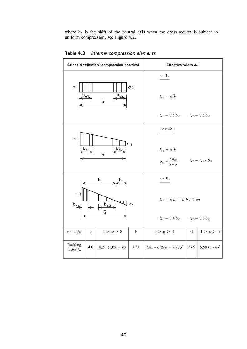
40
where eN is the shift of the neutral axis when the cross-section is subject to uniform compression, see Figure 4.2.
Table 4.3 Internal compression elements
Stress distribution (compression positive) Effective width beff
b e1
1 2
b e2b
:1
beff = b
be1 = 0,5 beff be2 = 0,5 beff
b e1 b e2
2
1
b
:01
beff = b
5
2 eff1
bbe
be2 = beff - be1
2
1
b b e1 e2
b b c t
b
:0
beff = bc = b / (1-)
be1 = 0,4 beff be2 = 0,6 beff
= 2/1 1 1 > > 0 0 0 > > -1 -1 -1 > > -3
Buckling factor k
4,0 8,2 / (1,05 + ) 7,81 7,81 – 6,29 + 9,782 23,9 5,98 (1 - )2

41
Table 4.4 Outstand compression elements
Stress distribution (compression positive) Effective width beff
21
c
b eff
:01
beff = c
1
b t
2 b eff
cb
:0
beff = bc = c / (1-)
= 2/1 1 0 -1 31
Buckling factor k 0,43 0,57 0,85 0,57 – 0,21 + 0,072
b eff
1
2
c
:01
beff = c
b eff
1
b b c t2
:0
beff = bc = c / (1-)
= 2/1 1 1 > > 0 0 0 > > -1 -1
Buckling factor k
0,43 0,578 / ( + 0,34) 1,70 1,7 - 5 + 17,12 23,8

42
Neutral axisof effective area
Non-effectivearea
Non-effectivearea
Neutralaxis
Neutralaxis
e
e
Neutralaxis ofeffectivearea
Effective cross-sectionGross cross-section
M
M
Figure 4.1 Class 4 cross-section subject to bending moment
Neutral axis ofgross cross-section
Neutral axisof effectivecross-sectione
Non-effective zones
Non-effectivezone
Gross cross-section Effective cross-section
N
Figure 4.2 Class 4 cross-section subject to compression
4.4.2 Effects of shear lag Shear lag in flanges may be neglected if b0 < Le /50, where b0 is taken as the flange outstand or half the width of an internal element and Le is the length between points of zero bending moment. Where this limit for b0 is exceeded, the effects of shear lag in flanges should be considered; the guidance for carbon steel in EN 1993-1-5 is applicable. Note that EN 1993-1-5 requires that shear lag be taken into account at both the ultimate and the serviceability limit states.
4.4.3 Flange curling The effect on the load bearing resistance of curling (i.e. inward curvature towards the neutral plane) of a very wide flange in a profile subjected to flexure, or of a flange in an arched profile subjected to flexure in which the concave side is in compression, should be taken into account unless such curling is less than 5% of the depth of the profile cross-section. If the curling is larger,
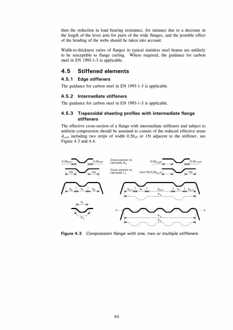
43
then the reduction in load bearing resistance, for instance due to a decrease in the length of the lever arm for parts of the wide flanges, and the possible effect of the bending of the webs should be taken into account.
Width-to-thickness ratios of flanges in typical stainless steel beams are unlikely to be susceptible to flange curling. Where required, the guidance for carbon steel in EN 1993-1-3 is applicable.
4.5 Stiffened elements 4.5.1 Edge stiffeners The guidance for carbon steel in EN 1993-1-3 is applicable.
4.5.2 Intermediate stiffeners The guidance for carbon steel in EN 1993-1-3 is applicable.
4.5.3 Trapezoidal sheeting profiles with intermediate flange stiffeners
The effective cross-section of a flange with intermediate stiffeners and subject to uniform compression should be assumed to consist of the reduced effective areas As,red including two strips of width 0,5beff or 15t adjacent to the stiffener, see Figure 4.3 and 4.4.
eff eff0,5b 0,5b 0,5b
15t
b b b b
15t 15t
b b b p p
b
p,1 p,1b p,2
b
e
e
b
b
b
min(15t;0,5b )p,2
a a
2,eff0,5b 1,effs
s
Cross section to calculate A
Cross section to calculate I
r
r
so
r r
Figure 4.3 Compression flange with one, two or multiple stiffeners
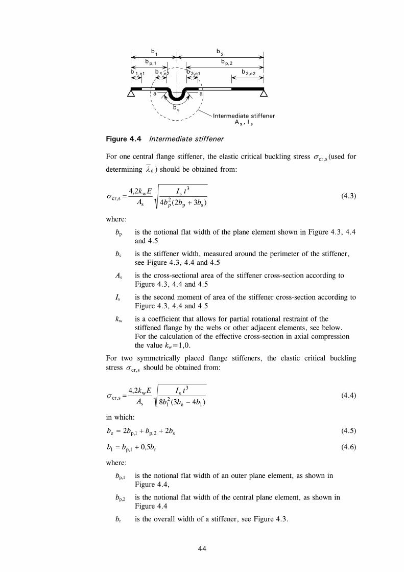
44
a a
bs
b b 1 2
p,1 p,2
b b
1,e1 1,e2 2,e1 2,e2b b b b
s
Intermediate stiffenerA , I s
Figure 4.4 Intermediate stiffener
For one central flange stiffener, the elastic critical buckling stress scr, (used for
determining d ) should be obtained from:
)32(4
2,4
sp2
3s
s
wscr,
bbb
tIA
Ek
p (4.3)
where:
bp is the notional flat width of the plane element shown in Figure 4.3, 4.4 and 4.5
bs is the stiffener width, measured around the perimeter of the stiffener, see Figure 4.3, 4.4 and 4.5
As is the cross-sectional area of the stiffener cross-section according to Figure 4.3, 4.4 and 4.5
Is is the second moment of area of the stiffener cross-section according to Figure 4.3, 4.4 and 4.5
kw is a coefficient that allows for partial rotational restraint of the stiffened flange by the webs or other adjacent elements, see below. For the calculation of the effective cross-section in axial compression the value kw=1,0.
For two symmetrically placed flange stiffeners, the elastic critical buckling stress scr, should be obtained from:
)43(8
2,4
1e21
3s
s
wscr,
bbb
tIA
Ek
(4.4)
in which:
s2,p1,pe 22 bbbb (4.5)
r1,p1 5,0 bbb (4.6)
where:
bp,1 is the notional flat width of an outer plane element, as shown in Figure 4.4,
bp,2 is the notional flat width of the central plane element, as shown in Figure 4.4
br is the overall width of a stiffener, see Figure 4.3.

45
The value of kw may be calculated from the compression flange buckling wavelength lb as follows:
if woww
b ,2 kksl
(4.7)
if
2
w
b
w
bwowow
w
b 2)1(,2
sl
sl
kkksl
(4.8)
where:
sw is the slant height of the web, see Figure 4.5.
r
m
m
a) Midpoint of corner or bend
X is intersection of midlinesP is midpoint of cornerr = r + t/2g = r [tan( /2) - sin( /2)]
/2
/2r
r p
pb
b
b
t
g
X
P
w
b swpw
c) Notional flat width b for a web(b slant height s )p
pw
s
hh
p
p,c
b) Notional flat width bof plane elements b, c and d
bb
b c
p pd) Notional flat width b of plane elementsadjacent to stiffeners
p pb
p,c
p,d
b c
b
d
b
pb
pb
Figure 4.5 Notional widths of plane elements bp allowing for corner radii
Alternatively, the rotational restraint coefficient kw may conservatively be taken as equal to 1,0 corresponding to a pin-jointed condition.
The values of lb and kwo may be determined from:
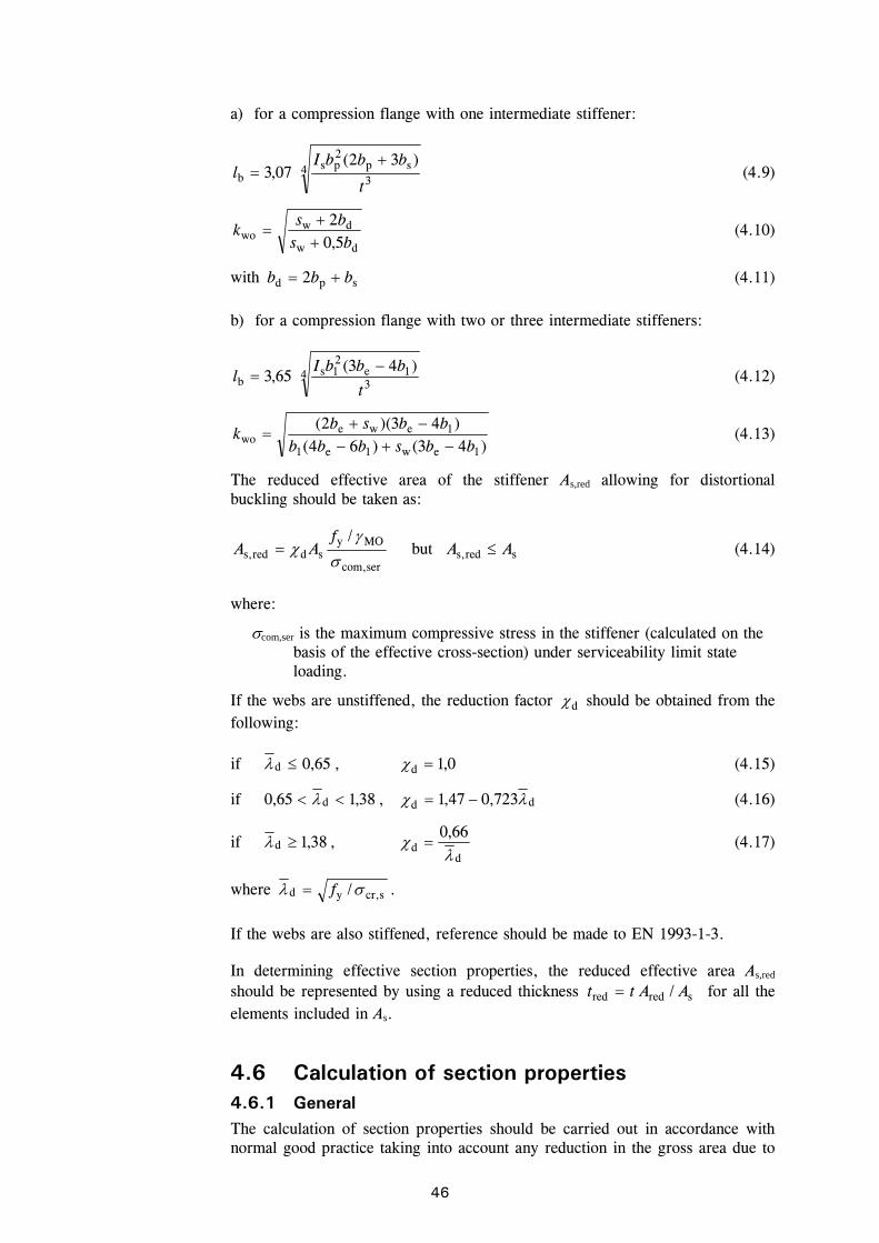
46
a) for a compression flange with one intermediate stiffener:
43
sp2ps
b)32(
07,3t
bbbIl
(4.9)
dw
dwwo 5,0
2bs
bsk
(4.10)
with spd 2 bbb (4.11)
b) for a compression flange with two or three intermediate stiffeners:
43
1e21s
b)43(
65,3t
bbbIl
(4.12)
)43()64()43)(2(
1ew1e1
1ewewo bbsbbb
bbsbk
(4.13)
The reduced effective area of the stiffener As,red allowing for distortional buckling should be taken as:
sercom,
MOysdreds,
/
f
AA but sreds, AA (4.14)
where:
com,ser is the maximum compressive stress in the stiffener (calculated on the basis of the effective cross-section) under serviceability limit state loading.
If the webs are unstiffened, the reduction factor d should be obtained from the following:
if 65,0d , 0,1d (4.15)
if 38,165,0 d , dd 723,047,1 (4.16)
if 38,1d , d
d66,0
(4.17)
where scr,yd / f .
If the webs are also stiffened, reference should be made to EN 1993-1-3.
In determining effective section properties, the reduced effective area As,red should be represented by using a reduced thickness sredred / AAtt for all the elements included in As.
4.6 Calculation of section properties 4.6.1 General The calculation of section properties should be carried out in accordance with normal good practice taking into account any reduction in the gross area due to
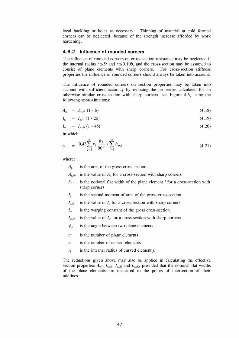
47
local buckling or holes as necessary. Thinning of material at cold formed corners can be neglected, because of the strength increase afforded by work hardening.
4.6.2 Influence of rounded corners The influence of rounded corners on cross-section resistance may be neglected if the internal radius r≤5t and r≤0.10bp and the cross-section may be assumed to consist of plane elements with sharp corners. For cross-section stiffness properties the influence of rounded corners should always be taken into account.
The influence of rounded corners on section properties may be taken into account with sufficient accuracy by reducing the properties calculated for an otherwise similar cross-section with sharp corners, see Figure 4.6, using the following approximations:
Ag = Ag,sh (1 - ) (4.18)
Ig = Ig,sh (1 - 2) (4.19)
Iw = Iw,sh (1 - 4) (4.20)
in which:
=
m
iipo
jn
jj br
1,
1
/90
43,0
(4.21)
where:
Ag is the area of the gross cross-section
Ag,sh is the value of Ag for a cross-section with sharp corners
bp,i is the notional flat width of the plane element i for a cross-section with sharp corners
Ig is the second moment of area of the gross cross-section
Ig,sh is the value of Ig for a cross-section with sharp corners
Iw is the warping constant of the gross cross-section
Iw,sh is the value of Iw for a cross-section with sharp corners
j is the angle between two plane elements
m is the number of plane elements
n is the number of curved elements
rj is the internal radius of curved element j.
The reductions given above may also be applied in calculating the effective section properties Aeff, Iy,eff, Iz,eff and Iw,eff, provided that the notional flat widths of the plane elements are measured to the points of intersection of their midlines.

48
Real cross-section
=
Idealised cross-section
b p,i
Figure 4.6 Real and idealised cross-section 4.6.3 Gross cross section When calculating gross cross section properties, holes for fasteners need not be deducted but allowance should be made for larger openings.
4.6.4 Net section The net area of a section or element of a section should be taken as its gross area less appropriate deductions for all openings, including holes for fasteners. In the deductions for fasteners, the nominal hole diameter should be used.
Provided that the fastener holes are not staggered, the total area to be deducted for fastener holes should be the maximum sum of the sectional areas of the holes in any cross-section perpendicular to the member axis (see failure plane (2) in Figure 4.7).
When the fastener holes are staggered, the total area to be deducted should be the greater of:
the deduction for non-staggered holes
p
sndt
4
2
0
where:
s is the staggered pitch, the spacing of the centres of two consecutive holes in the chain measured parallel to the member axis
p is the spacing of the centres of the same two holes measured perpendicular to the member axis
t is the thickness
n is the number of holes extending in any diagonal or zig-zag line progressively across the member or part of the member, see Figure 4.7
d0 is the diameter of the hole.
For sections such as angles with holes in both legs, the gauge should be measured along the centre of the thickness of the material, see Figure 4.8.
For angles connected by one leg, see Section 6.2.
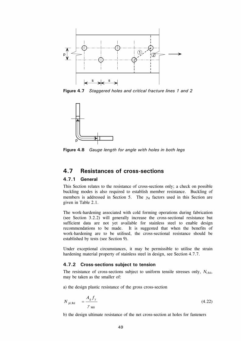
49
4.7 Resistances of cross-sections 4.7.1 General This Section relates to the resistance of cross-sections only; a check on possible buckling modes is also required to establish member resistance. Buckling of members is addressed in Section 5. The M factors used in this Section are given in Table 2.1.
The work-hardening associated with cold forming operations during fabrication (see Section 3.2.2) will generally increase the cross-sectional resistance but sufficient data are not yet available for stainless steel to enable design recommendations to be made. It is suggested that when the benefits of work-hardening are to be utilised, the cross-sectional resistance should be established by tests (see Section 9).
Under exceptional circumstances, it may be permissible to utilise the strain hardening material property of stainless steel in design, see Section 4.7.7.
4.7.2 Cross-sections subject to tension The resistance of cross-sections subject to uniform tensile stresses only, Nt.Rd, may be taken as the smaller of:
a) the design plastic resistance of the gross cross-section
M0
ygRdpl,
fAN (4.22)
b) the design ultimate resistance of the net cross-section at holes for fasteners
12
s s
p
Figure 4.7 Staggered holes and critical fracture lines 1 and 2
p
Figure 4.8 Gauge length for angle with holes in both legs
50
M2
unetrRdu,
fAkN (4.23)
where:
Ag is the gross area
Anet is the net cross-sectional area (see Section 4.6.4)
fy is the characteristic yield strength (generally taken as the minimum specified 0,2% proof strength, see Table 3.1)
fu is the characteristic ultimate tensile strength (generally taken as the minimum specified value, see Table 3.1)
kr = )]3,0/(31[ 0 udr but 0,1rk (4.24)
r = [number of bolts at the cross-section]/[total number of bolts in the connection]
d0 is the nominal bolt hole diameter
u = 2e2 but 2pu .
4.7.3 Cross-sections subject to compression The resistance of a cross-section subject to compression, Nc,Rd, with a resultant acting through the centroid of the gross section (for Class 1, 2 and 3 cross-sections) or the effective section (Class 4 cross-sections) may be taken as:
Nc.Rd = Ag fy/M0 for Class 1, 2 or 3 cross-sections (4.25)
Nc.Rd = Aeff fy/M0 for Class 4 cross-sections (4.26)
Note: Class 4 sections which are not doubly symmetric should be assessed in accordance with 4.7.6 to account for the additional bending moment MEd due to the eccentricity of the centroidal axial of the effective sections, see Section 4.4.1.
4.7.4 Cross-sections subject to bending moment In the absence of shear and axial forces, the design moment resistance of a cross-section subject to a uniaxial moment, Mc,Rd, should be taken as:
Mc,Rd = Wpl fy/M0 for Class 1 or 2 cross-sections (4.27)
Mc,Rd = Wel,min fy/M0 for Class 3 cross-sections (4.28)
Mc,Rd = Weff,min fy/M0 for Class 4 cross-sections (4.29)
where:
Wpl is the plastic section modulus
Wel,min is the elastic section modulus corresponding to the fibre with the maximum elastic stress (but see Section 4.1 for cold formed cross-sections)
Weff,min is the elastic modulus of effective section corresponding to the fibre with the maximum elastic stress (but see Section 4.1 for cold formed cross-sections).
51
For cross-sections where bending is applied about both axes, see Section 4.7.6.
4.7.5 Cross-sections subject to shear The plastic shear resistance of a cross-section, Vpl,Rd may generally be taken as:
pl,Rd v y M0( / 3) /V A f (4.30)
where:
Av is the shear area, which may be taken as follows:
a) rolled I and H sections, load parallel to web fwf trtbtA 22 but not less than wwth
b) rolled channel sections, load parallel to web fwf trtbtA 2
c) rolled T-section, load parallel to web f9,0 btA
d) welded I, H and box sections, load parallel to web ww th
e) welded I, H, channel and box section, load parallel to flanges ww thA
f) rolled rectangular hollow sections of uniform thickness
i. load parallel to depth )/( hbAh
ii. load parallel to width )/( hbAb
g) circular hollow sections and tubes of uniform thickness /2A
where:
A is the cross-sectional area
b is the overall breadth
h is the overall depth
hw is the depth of the web
r is the root radius
tf is the flange thickness
tw is the web thickness (if the web thickness is not constant, tw should be taken as the minimum thickness).
see EN 1993-1-5. (EN 1993-1-4 recommends = 1,20.)
Note: The same value of should be used for calculating the shear buckling resistance as is used for calculating the plastic shear resistance.
The resistance to shear buckling should be also checked, see Section 5.4.3.
4.7.6 Cross-sections subject to combination of loads When an axial force is present, allowance should be made for its effect on the plastic moment resistance. For Class 1 and 2 cross sections, the following criterion should be satisfied:
52
RdN,Ed MM (4.31)
where:
MN,Rd is the design plastic moment resistance reduced due to the axial force NEd.
For doubly symmetrical I- and H-sections or other flange sections, allowance need not be made for the effect of the axial force on the plastic resistance moment about the y-y axis when both the following criteria are satisfied:
Rdpl,Ed 25,0 NN and (4.32a)
M0ywwEd /5,0 fthN (4.32b)
In the absence of shear force, for Class 3 and Class 4 cross-sections the maximum longitudinal stress should satisfy the criterion:
x,Ed y M0/f (4.33)
where:
Edx, is the design value of the local longitudinal stress due to moment and
axial force, taking account of fastener holes where relevant.
For Class 4 cross-sections, the following criterion should also be met:
10min,,
NzEdEdz,
0min,,
NyEdEdy,
0
Ed
MyzeffMyyeffMyeff fW
eNM
fW
eNM
fA
N
(4.34)
where:
Aeff is the effective area of the cross-section when subjected to uniform compression
Weff,min is the effective section modulus of the cross-section when subjected only to moment about the relevant axis
eN is the shift of the relevant centroidal axis when the cross-section is subjected to compression only.
Note that for angles, the y and z axes in the above should be taken as the u and v axes respectively.
When VEd exceeds 50% of Vpl.Rd, the design resistance of the cross-section to combinations of moment and axial force should be calculated using a reduced yield strength (1 - ) fy for the shear area, where = (2VEd/ Vpl.Rd -1)2.
4.7.7 Utilisation of strain hardening behaviour In certain circumstances, such as beams under short term accidental loads, it is permissible to recognise the benefits of the strain hardening properties of stainless steel more fully in design.
This may be achieved by utilising an enhanced proof stress, 0, in place of the 0,2% proof stress fy in all calculations. It is recommended that in the absence of a more detailed appraisal, perhaps involving non-linear finite element analysis, the following restrictions should be observed:
53
The cross-section should be of Class 1 or Class 2 as calculated by using 0 in place of fy when calculating in Table 4.2.
The cross-section is subject to major axis bending only.
The member concerned is not subject to instability caused by any form of buckling (flexural, torsional, lateral-torsional or distortional - see Section 5), again using 0 in all calculations.
Connections to adjacent members and the members themselves are sufficiently strong to realise the enhanced resistance of the member.
Particular attention should be given to assessing connection strength requirements.
For Class 3 and 4 cross-sections, enhanced strengths may be used provided these values are verified by testing in accordance with Section 9.
54
5 MEMBER DESIGN
5.1 Introduction The design checks required for stainless steel members are similar to those required for carbon steel members. It is recommended that the forces and moments in the members are derived from an elastic global analysis.
In addition to the cross-sectional resistance, see Section 4, consideration should be given to overall buckling of members, as addressed in this section.
A possible design approach for checking against buckling in stainless steel members is to use the tangent modulus corresponding to the buckling stress instead of the initial modulus as used in carbon steel rules. Assuming similar levels of geometric and residual stress imperfections in carbon steel and stainless steel members, this generally leads to satisfactory results when it is based on validated carbon steel rules. This approach is therefore available to the designer. However, it requires iterative solution techniques and therefore has been avoided in this Design Manual except in some cases when it has been used to derive effective design curves for use with the initial modulus. Instead, emphasis has been given to calibrating against available experimental data.
The following subsections are intended for use with singly, doubly or point-symmetric uniform sections. The resistance of members not possessing any axis of symmetry should be verified by appropriate tests.
5.2 Tension members Members subject to tension only do not suffer any instability due to buckling. Their design may therefore be based only on the cross-section resistance, see Section 4.7.2, and the resistance of their connections, see Section 6.
For an angle connected by one leg or other unsymmetrically connected members:
Rdu,Rdpl,Rdt, NNN (5.1)
where the terms are defined in Section 4.7.2 and Nu,Rd is determined from Section 6.2.3, Equations 6.6, 6.7 or 6.8.
5.3 Compression members 5.3.1 General Members in compression are susceptible to a number of possible buckling modes including:
Plate buckling (Class 4 sections only)
Flexural buckling
Torsional buckling
Torsional-flexural buckling.
55
Doubly symmetric cross-sections (CHS, RHS, I sections etc.)
Doubly symmetric cross-sections need not be checked for torsional-flexural buckling, since the shear centre coincides with the centroid of the cross-section. However, torsional buckling may be critical.
Circular and square hollow sections will not fail by torsional buckling.
For the range of rectangular hollow section sizes typically used in construction, torsional buckling will not be critical. Torsional buckling in rectangular hollow sections need only be considered for rectangular hollow sections with unusually high h/b ratios.
Singly symmetric cross-sections (equal-leg angles, channels etc.) It is necessary to check sections such as single channels and equal-leg angles for torsional-flexural buckling as the shear centre does not coincide with the centroid of the cross-section.
Point symmetric cross-sections (Z-sections, cruciform sections etc.) Torsional buckling may be the critical buckling mode for these sections.
5.3.2 Plate buckling Plate buckling within Class 4 sections is taken into account by the use of an effective cross-section area. Note that the additional moment caused by the shift in neutral axis of the effective section from that of the gross section in asymmetric Class 4 cross-sections should be considered in accordance with Section 5.5.
5.3.3 Flexural buckling The resistance to flexural buckling should be determined from:
Nb,Rd = A fy / M1 for Class 1, 2 and 3 cross-sections (5.2a)
Nb,Rd = Aeff fy / M1 for Class 4 cross-sections (5.2b)
where:
Aeff is the effective area of Class 4 cross-section
A is the gross area
is the reduction factor accounting for buckling, given by:
11
5,022
(5.3)
in which:
2015,0 (5.4)
E
f
i
L
N
Af ycr
cr
y 1
for Class 1, 2 and 3 cross-sections (5.5a)
EA
Af
i
L
N
fA yeff
cr
cr
yeff 1
for Class 4 cross-sections (5.5b)
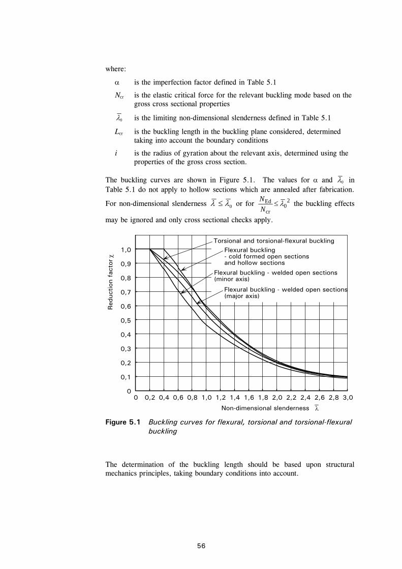
56
where:
is the imperfection factor defined in Table 5.1
Ncr is the elastic critical force for the relevant buckling mode based on the gross cross sectional properties
0 is the limiting non-dimensional slenderness defined in Table 5.1
Lcr is the buckling length in the buckling plane considered, determined taking into account the boundary conditions
i is the radius of gyration about the relevant axis, determined using the properties of the gross cross section.
The buckling curves are shown in Figure 5.1. The values for and 0 in Table 5.1 do not apply to hollow sections which are annealed after fabrication.
For non-dimensional slenderness 0 or for 20
cr
Ed N
N the buckling effects
may be ignored and only cross sectional checks apply.
The determination of the buckling length should be based upon structural mechanics principles, taking boundary conditions into account.
00
Red
uction
fac
tor
Non-dimensional slenderness
1,0
0,9
0,8
0,7
0,6
0,5
0,4
0,3
0,2
0,1
0,2 0,4 0,6 0,8 1,0 1,2 1,4 1,6 1,8 2,0 2,2 2,4 2,6 2,8 3,0
Flexural buckling - welded open sections(major axis)
Flexural buckling - welded open sections(minor axis)
Torsional and torsional-flexural bucklingFlexural buckling- cold formed open sectionsand hollow sections
Figure 5.1 Buckling curves for flexural, torsional and torsional-flexural
buckling
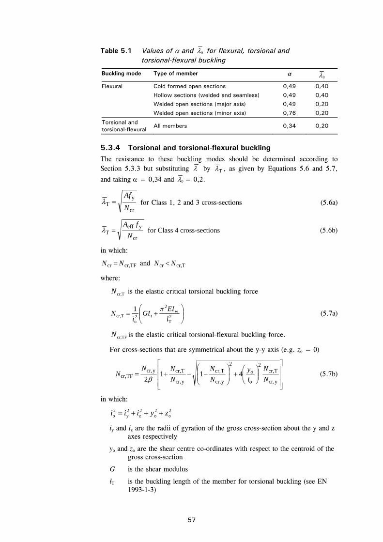
57
Table 5.1 Values of and 0 for flexural, torsional and torsional-flexural buckling
Buckling mode Type of member 0
Flexural Cold formed open sections 0,49 0,40
Hollow sections (welded and seamless) 0,49 0,40
Welded open sections (major axis) 0,49 0,20
Welded open sections (minor axis) 0,76 0,20
Torsional and torsional-flexural
All members 0,34 0,20
5.3.4 Torsional and torsional-flexural buckling The resistance to these buckling modes should be determined according to Section 5.3.3 but substituting by T , as given by Equations 5.6 and 5.7,
and taking = 0,34 and 0 = 0,2.
cr
yT N
Af for Class 1, 2 and 3 cross-sections (5.6a)
cr
yeffT N
fA for Class 4 cross-sections (5.6b)
in which:
TFcr,cr NN and Tcr,cr NN
where:
Tcr,N is the elastic critical torsional buckling force
2T
w2
t2o
Tcr,
1
l
EIGI
iN
(5.7a)
TFcr,N is the elastic critical torsional-flexural buckling force.
For cross-sections that are symmetrical about the y-y axis (e.g. zo = 0)
ycr,
Tcr,22
ycr,
Tcr,
ycr,
Tcr,ycr,TFcr, 411
2 N
N
i
y
N
N
N
NNN
o
o
(5.7b)
in which:
2o
2o
2z
2y
2o zyiii
iy and iz are the radii of gyration of the gross cross-section about the y and z axes respectively
yo and zo are the shear centre co-ordinates with respect to the centroid of the gross cross-section
G is the shear modulus
lT is the buckling length of the member for torsional buckling (see EN 1993-1-3)
58
IT is the torsional constant of the gross cross-section
IW is the warping constant of the gross cross-section
2
1
o
o
i
y
Ncr,y and Ncr,z are the elastic critical axial force for flexural buckling about the y-y and z-z axes respectively.
For a doubly symmetric cross-section, the shear centre coincides with the centroid, therefore yo = 0 and zo = 0 and
Tcr,TFcr, NN provided ycr,Tcr, NN and zcr,Tcr, NN .
Note that for angles, the y and z axes in the above should be taken as the u and v axes respectively.
5.4 Flexural members 5.4.1 General A member is in simple bending under loads acting normal to the longitudinal axis if it is connected in such a way as to eliminate twisting or tensile or compressive end loading.
The following criteria should be considered for establishing the moment resistance of a beam:
Yielding of the cross-section (see Section 4.7)
Plate buckling (Class 4 section only – see Section 4.7)
Lateral-torsional buckling (see Section 5.4.2)
Shear buckling (see Section 5.4.3)
Local strength at points of loading or reaction (see Section 5.4.4).
Note that for flexural members, the effects of shear lag and flange curling may have to be accounted for in design, see Sections 4.4.2 and 4.4.3.
Biaxial bending should be treated as described in Section 5.5.2.
5.4.2 Lateral-torsional buckling The possibility of lateral-torsional buckling may be discounted for the following classes of member:
beams subject to bending only about the minor axis
beams laterally restrained throughout their length by adequate bracing
beams where the lateral non-dimensional slenderness parameter LT (see
below) 0,4 or for 16,0cr
Ed M
M.
For all other classes of member, the resistance to lateral torsional buckling should be determined from:
59
Mb,Rd = LT Wy fy/M1 (5.8)
where:
Wy = Wpl,y for Class 1 or 2 cross-sections
Wy = Wel,y for Class 3 cross-sections
Wy = Weff,y for Class 4 cross-sections
LT is a reduction factor accounting for lateral torsional buckling, given by:
11
5.02LT
2LTLT
LT
(5.9)
in which:
2LTLTLTLT 4,015,0 (5.10)
cr
yyLT M
fW (5.11)
LT is the imperfection factor
= 0,34 for cold formed sections and hollow sections (welded and seamless)
= 0,76 for welded open sections and other sections for which no test data is available.
Mcr is the elastic critical moment for lateral torsional buckling (Appendix B).
Note that for angles, the y and z axes in the above should be taken as the u and v axes respectively.
The buckling curves for lateral torsional buckling are shown in Figure 5.2.
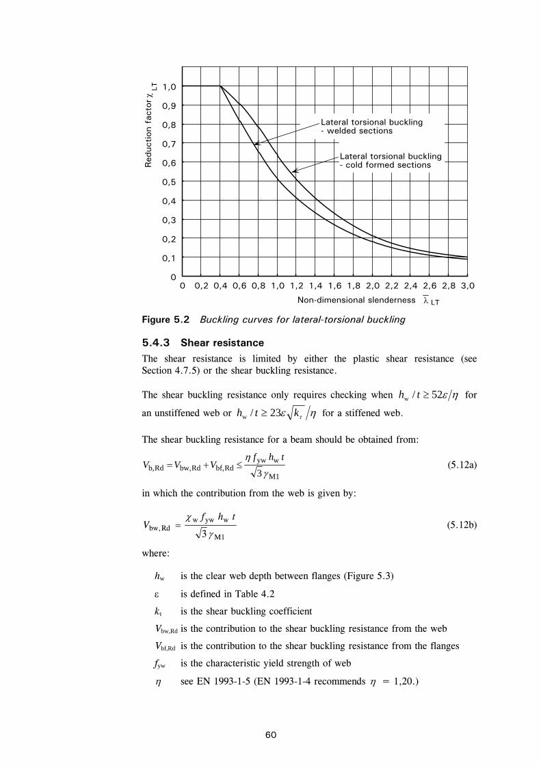
60
5.4.3 Shear resistance The shear resistance is limited by either the plastic shear resistance (see Section 4.7.5) or the shear buckling resistance.
The shear buckling resistance only requires checking when 52/w th for
an unstiffened web or kth 23/w for a stiffened web.
The shear buckling resistance for a beam should be obtained from:
M1
wywRdbf,Rdbw,Rdb,
3
thfVVV (5.12a)
in which the contribution from the web is given by:
M1
wywwRdbw,
3
thfV (5.12b)
where:
hw is the clear web depth between flanges (Figure 5.3)
is defined in Table 4.2
kτ is the shear buckling coefficient
Vbw,Rd is the contribution to the shear buckling resistance from the web
Vbf,Rd is the contribution to the shear buckling resistance from the flanges
fyw is the characteristic yield strength of web
see EN 1993-1-5 (EN 1993-1-4 recommends = 1,20.)
00
Red
uction
fac
tor
Non-dimensional slenderness LT
LTLateral torsional buckling- cold formed sections
Lateral torsional buckling- welded sections
1,0
0,9
0,8
0,7
0,6
0,5
0,4
0,3
0,2
0,1
0,2 0,4 0,6 0,8 1,0 1,2 1,4 1,81,6 2,0 2,2 2,4 2,6 2,8 3,0
Figure 5.2 Buckling curves for lateral-torsional buckling
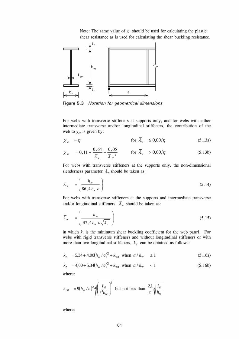
61
Note: The same value of should be used for calculating the plastic shear resistance as is used for calculating the shear buckling resistance.
For webs with transverse stiffeners at supports only, and for webs with either intermediate transverse and/or longitudinal stiffeners, the contribution of the web to w is given by:
w for 60,0w (5.13a)
2ww
w05,064,0
11,0
for 60,0w (5.13b)
For webs with transverse stiffeners at the supports only, the non-dimensional slenderness parameter w should be taken as:
w
ww
4,86 t
h (5.14)
For webs with transverse stiffeners at the supports and intermediate transverse and/or longitudinal stiffeners, w should be taken as:
kt
h
w
ww
4,37 (5.15)
in which k is the minimum shear buckling coefficient for the web panel. For webs with rigid transverse stiffeners and without longitudinal stiffeners or with more than two longitudinal stiffeners, k can be obtained as follows:
τst2
w /00,434,5 kahk when 1/ w ha (5.16a)
τst2
w /34,500,4 kahk when 1/ w ha (5.16b)
where:
4
3
w3
sl2w /9
ht
Iahk st but not less than 3
w
sl1,2
h
I
t
where:
ff
t
t
tf
hw
a
w
b
Figure 5.3 Notation for geometrical dimensions

62
a is the distance between centrelines of transverse stiffeners, see Figure 5.3.
slI is the second moment of area of the longitudinal stiffener about the z-axis.
Equation 5.16 also applies to plates with one or two longitudinal stiffeners, if the aspect ratio a/hw 3. For plates with one or two longitudinal stiffeners and an aspect ratio a/hw 3 , reference should be made to EN 1993-1-5 Annex A3.
For simplicity, the contribution from the flanges f may be neglected. However, if the flange resistance is not completely utilized in withstanding the bending moment (MEd < Mf,Rd) then the contribution from the flanges may be obtained as follows:
2
Rdf,
Ed
M1
yf2ff
Rdbf, 1M
M
c
ftbV
(5.17)
where:
fb and ft are taken for the flange which provides the least axial resistance,
fb being taken as not larger than 15tf on each side of the web
Rdf,M is the moment of resistance of the cross section consisting of the area
of the effective flanges only
M0
kf,Rdf,
MM
yw2
ww
yf2
ff5,317,0
fht
ftbac and 65,0
a
c
fyf is the characteristic yield strength of the flange.
If an axial force NEd is also applied, the value of Mf,Rd should be reduced by a factor:
M0
yff2f1
Ed1
fAA
N (5.18)
where Af1 and Af2 are the areas of the top and bottom flanges, respectively.
The verification should be performed as follows:
0,1Rdb,
Ed3
V
V (5.19)
where:
VEd is the design shear force including shear from torque.
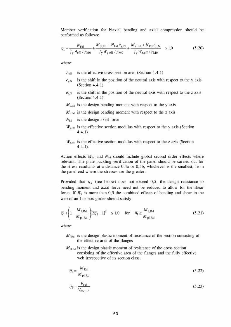
63
Member verification for biaxial bending and axial compression should be performed as follows:
0,1/// M0effz,y
Nz,EdEdz,
M0effy,y
Ny,EdEdy,
M0effy
Ed1
Wf
eNM
Wf
eNM
Af
N (5.20)
where:
Aeff is the effective cross-section area (Section 4.4.1)
ey,N is the shift in the position of the neutral axis with respect to the y axis (Section 4.4.1)
ez,N is the shift in the position of the neutral axis with respect to the z axis (Section 4.4.1)
My,Ed is the design bending moment with respect to the y axis
Mz,Ed is the design bending moment with respect to the z axis
NEd is the design axial force
Wy,eff is the effective section modulus with respect to the y axis (Section 4.4.1)
Wz,eff is the effective section modulus with respect to the z azis (Section 4.4.1).
Action effects MEd and NEd should include global second order effects where relevant. The plate buckling verification of the panel should be carried out for the stress resultants at a distance 0,4a or 0,5b, whichever is the smallest, from the panel end where the stresses are the greater.
Provided that 3 (see below) does not exceed 0,5, the design resistance to bending moment and axial force need not be reduced to allow for the shear force. If 3 is more than 0,5 the combined effects of bending and shear in the web of an I or box girder should satisfy:
0,1121 23
Rdpl,
Rdf,1
M
M for
Rdpl,
Rdf,1 M
M (5.21)
where:
Mf,Rd is the design plastic moment of resistance of the section consisting of the effective area of the flanges
Mpl,Rd is the design plastic moment of resistance of the cross section consisting of the effective area of the flanges and the fully effective web irrespective of its section class.
Rdpl,
Ed1 M
M (5.22)
Rdbw,
Ed3 V
V (5.23)

64
Stresses are taken as positive. MEd and VEd should include second order effects where relevant.
The criterion given in Equation 5.21 should be verified at all sections other than those located at a distance less than hw/2 from a support with vertical stiffeners.
If an axial force NEd is present, then Mpl,Rd should be replaced by the reduced plastic resistance moment MN,Rd according to 6.2.9 of EN 1993-1-1 and Mf,Rd should be reduced according to Equation 5.18. Reference should be made to EN 1993-1-5 if the axial force is so large that the whole web is in compression.
5.4.4 Web crushing, crippling and buckling Provided that the flanges are laterally restrained, the resistance of an unstiffened web to forces from concentrated loads or support reactions will be governed by one of three possible failure modes:
crushing of the web close to the flange, accompanied by plastic deformation of the flange
crippling of the web in the form of localised buckling and crushing of the web close to the flange, accompanied by plastic deformation of the flange
buckling of the web over most of the depth of the member.
For cold formed structural sections, the guidance in EN 1993-1-3 for carbon steel can be adopted.
For rolled beams and welded girders, the following approach should be adopted, based on the guidance in EN 1993-1-5.
For unstiffened or stiffened webs the design resistance to local buckling under transverse forces should be taken as:
1MweffywRd /tLfF (5.24)
where:
tw is the thickness of the web
fyw is the yield strength of the web
Leff is the effective length for resistance to transverse forces, which should be determined from
yF lL eff
where:
yl is the effective loaded length appropriate to the length of stiff bearing
ss
F is the reduction factor due to local buckling
In addition the effect of the transverse force on the moment resistance of the member should be considered.
To determine Leff, a distinction should be made between three types of force application, as follows:
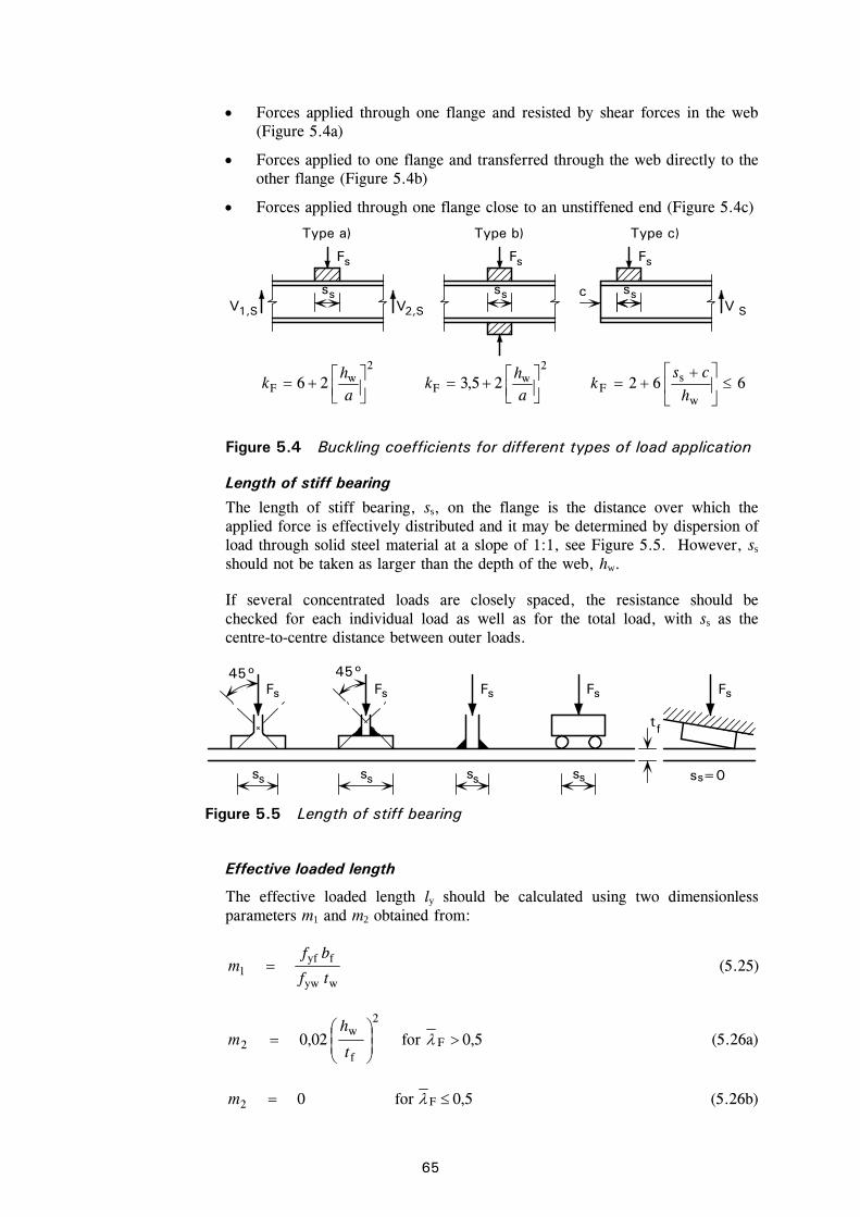
65
Forces applied through one flange and resisted by shear forces in the web (Figure 5.4a)
Forces applied to one flange and transferred through the web directly to the other flange (Figure 5.4b)
Forces applied through one flange close to an unstiffened end (Figure 5.4c)
Length of stiff bearing
The length of stiff bearing, ss, on the flange is the distance over which the applied force is effectively distributed and it may be determined by dispersion of load through solid steel material at a slope of 1:1, see Figure 5.5. However, ss should not be taken as larger than the depth of the web, hw.
If several concentrated loads are closely spaced, the resistance should be checked for each individual load as well as for the total load, with ss as the centre-to-centre distance between outer loads.
Effective loaded length
The effective loaded length ly should be calculated using two dimensionless parameters m1 and m2 obtained from:
wyw
fyf1 tf
bfm (5.25)
5,0for02,0 F
2
f
w2
t
hm (5.26a)
5,0for0 F2 m (5.26b)
ss VV
Fs
Type a)
V
Type c)
ss
Fs
ss
Fs
Type b)
cS1,S 2,S
2
wF 26
ah
k 2
wF 25,3
ah
k 662w
sF
h
csk
Figure 5.4 Buckling coefficients for different types of load application
ss
Fs Fs
s s
Fs
s s
45°
ss
Fs
tf
Fs
ss =0
45°
Figure 5.5 Length of stiff bearing

66
For cases a) and b) in Figure 5.4, ly should be obtained using
21fsy 12 mmtsl (5.27)
but ly should not exceed the distance between adjacent transverse stiffeners.
For case c) ly should be obtained as the smaller of the values given by Equations 5.28 and 5.29. In Equations 5.30, ss should be taken as zero if the structure that introduces the force does not follow the slope of the girder, see Figure 5.5.
2
2
f
e1fey
2m
t
lmtll (5.28)
21fey mmtll (5.29)
where le is given by:
cshf
Etkl s
wyw
2wF
e2
(5.30)
Effective length of resistance
The effective length of resistance should be obtained from:
yFeff lL (5.31)
with
0.15,0
FF
(5.32)
cr
ywwyF
F
ftl (5.33)
w
3w
Fcr 9,0ht
EkF (5.34)
where:
kF is the buckling coefficient for different types of force application (Figure 5.4).
It should be noted that in order to calculate m2, a value of F needs to be
assumed. Once the value of F has been calculated, the value of m2 may need to be recalculated.
5.4.5 Transverse stiffeners Transverse stiffeners at supports and at other positions where significant external forces are applied should preferably be double-sided and symmetric about the centreline of the web. These stiffeners should be checked for
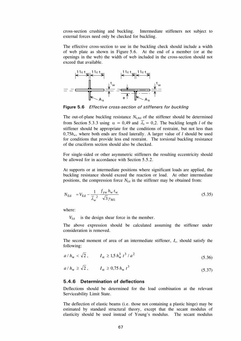
67
cross-section crushing and buckling. Intermediate stiffeners not subject to external forces need only be checked for buckling.
The effective cross-section to use in the buckling check should include a width of web plate as shown in Figure 5.6. At the end of a member (or at the openings in the web) the width of web included in the cross-section should not exceed that available.
The out-of-plane buckling resistance Nb,Rd of the stiffener should be determined from Section 5.3.3 using = 0,49 and 0 = 0,2. The buckling length l of the stiffener should be appropriate for the conditions of restraint, but not less than 0,75hw, where both ends are fixed laterally. A larger value of l should be used for conditions that provide less end restraint. The torsional buckling resistance of the cruciform section should also be checked.
For single-sided or other asymmetric stiffeners the resulting eccentricity should be allowed for in accordance with Section 5.5.2.
At supports or at intermediate positions where significant loads are applied, the buckling resistance should exceed the reaction or load. At other intermediate positions, the compression force NEd in the stiffener may be obtained from:
M1
wwyw2EdEd
3
1
thfVN
w
(5.35)
where:
VEd is the design shear force in the member.
The above expression should be calculated assuming the stiffener under consideration is removed.
The second moment of area of an intermediate stiffener, Is, should satisfy the following:
233wstw /5,1,2/ athIha (5.36)
3wstw 75,0,2/ thIha (5.37)
5.4.6 Determination of deflections Deflections should be determined for the load combination at the relevant Serviceability Limit State.
The deflection of elastic beams (i.e. those not containing a plastic hinge) may be estimated by standard structural theory, except that the secant modulus of elasticity should be used instead of Young's modulus. The secant modulus
w11 t w11 t w11 t w11 t
tw tw
As Ase
Figure 5.6 Effective cross-section of stiffeners for buckling

68
varies with the stress level in the beam and values may be found in Appendix C. This is a simplified method which is accurate for predicting deflections when the secant modulus is based on the maximum stress in the member and this maximum stress does not exceed 65% of the 0,2% proof strength. At higher levels of stress, the method becomes very conservative and a more accurate method (e.g. one which involves integrating along the length of the member) should be used.
In the case of Class 4 cross-sections and/or members subject to shear lag, an effective section should be used in the calculations. As a first estimate, it is appropriate to use the effective section based on the effective widths established in Sections 4.4.1 and/or 4.4.2. As a refinement, it is possible to use an effective section based on the effective buckling widths determined for the actual stress in the elements by taking in Section 4.4.1 (but not in Section 4.4.2) as:
2/1
000210
235
E
(5.38)
where:
is the actual stress in the element in the associated effective cross-section
E is Young’s modulus.
5.5 Members subject to combinations of axial load and bending moments
5.5.1 Axial tension and bending Tension members with moments should be checked for resistance to lateral torsional buckling in accordance with Section 5.4.2 under the moment alone. They should also be checked for capacity under the combined effects of axial load and moment at the points of maximum bending moment and axial load. The following relationship should be satisfied:
1Rdz,
Edz,
Rdy,
Edy,
Rd
Ed M
M
M
M
NN
(5.39)
where:
NEd is the design axial tensile load in the member at the critical location
NRd is the design resistance of the member in tension
My,Ed is the design moment about the major axis at the critical section
Mz,Ed is the design moment about the minor axis at the critical section
My,Rd is the design moment resistance about the major axis in the absence of axial load and include any reduction that may be cased by shear effects (Section 4.7.4)
Mz,Rd is the design moment about the minor axis in the absence of axial load and includes any reduction that may be cased by shear effects (Section 4.7.4).
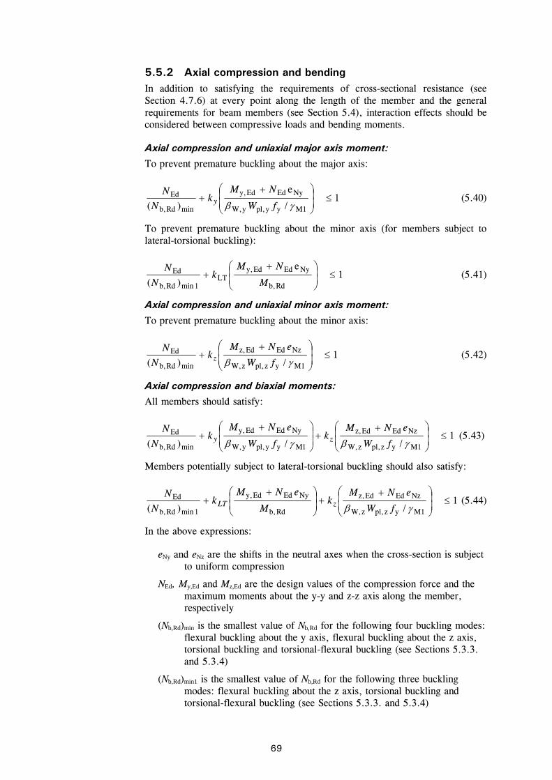
69
5.5.2 Axial compression and bending In addition to satisfying the requirements of cross-sectional resistance (see Section 4.7.6) at every point along the length of the member and the general requirements for beam members (see Section 5.4), interaction effects should be considered between compressive loads and bending moments.
Axial compression and uniaxial major axis moment:
To prevent premature buckling about the major axis:
1/
e
)( M1yypl,yW,
NyEdEdy,
minRdb,
Ed
fW
NMk
N
Ny (5.40)
To prevent premature buckling about the minor axis (for members subject to lateral-torsional buckling):
1e
)( Rdb,
NyEdEdy,LT
1minRdb,
Ed
M
NMk
N
N (5.41)
Axial compression and uniaxial minor axis moment:
To prevent premature buckling about the minor axis:
1/)( M1yzpl,zW,
NzEdEdz,
minRdb,
Ed
fW
eNMk
N
Nz (5.42)
Axial compression and biaxial moments:
All members should satisfy:
1//)( M1yzpl,zW,
NzEdEdz,
1Myypl,yW,
NyEdEdy,
minRdb,
Ed
fW
eNMk
fW
eNMk
N
Nzy (5.43)
Members potentially subject to lateral-torsional buckling should also satisfy:
1/)( M1yzpl,zW,
NzEdEdz,
Rdb,
NyEdEdy,
1minRdb,
Ed
fW
eNMk
M
eNMk
N
NzLT (5.44)
In the above expressions:
eNy and eNz are the shifts in the neutral axes when the cross-section is subject to uniform compression
NEd, My,Ed and Mz,Ed are the design values of the compression force and the maximum moments about the y-y and z-z axis along the member, respectively
(Nb,Rd)min is the smallest value of Nb,Rd for the following four buckling modes: flexural buckling about the y axis, flexural buckling about the z axis, torsional buckling and torsional-flexural buckling (see Sections 5.3.3. and 5.3.4)
(Nb,Rd)min1 is the smallest value of Nb,Rd for the following three buckling modes: flexural buckling about the z axis, torsional buckling and torsional-flexural buckling (see Sections 5.3.3. and 5.3.4)
70
W,y and W,z are the values of W determined for the y and z axes respectively in which
W = 1 for Class 1 or 2 cross-sections
= Wel/Wpl for Class 3 cross-sections
= Weff/Wpl for Class 4 cross-sections
Wpl,y and Wpl,z are the plastic moduli for the y and z axes respectively
Mb,Rd is the lateral-torsional buckling resistance (see Section 5.4.2)
ky, kz, kLT are the interaction factors
yRd,b,
Edyy 5,020,1
N
Nk but
yRd,b,
Edy 22,12,1
N
Nk
1minRdb,
Edzz 5,020,1
N
Nk but
1minRdb,
Edz 22,12,1
N
Nk
0,1LT k
Note that the National Annexes may give other interaction formulae as alternatives to the above equations.
Note that for angles, the y and z axes in the above should be taken as the u and v axes respectively.
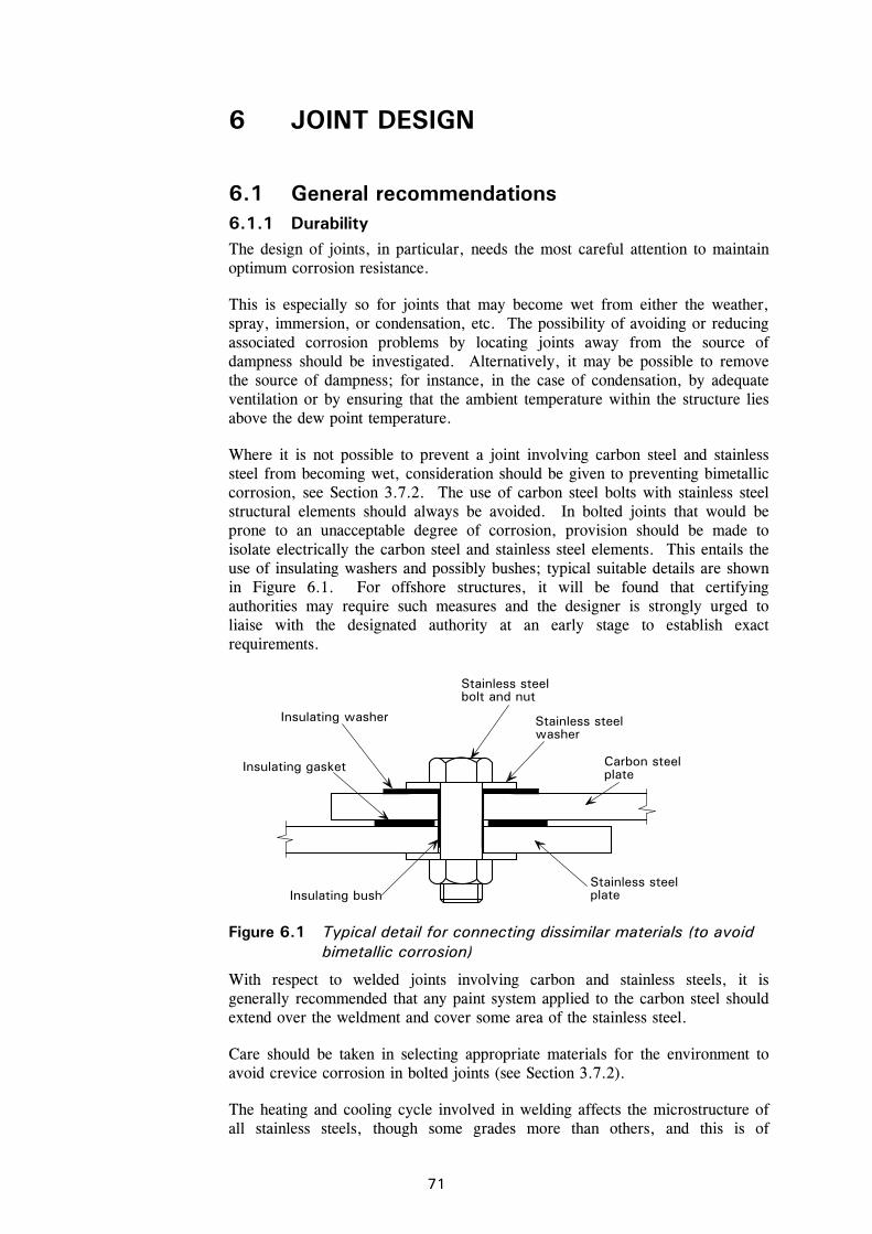
71
6 JOINT DESIGN
6.1 General recommendations 6.1.1 Durability The design of joints, in particular, needs the most careful attention to maintain optimum corrosion resistance.
This is especially so for joints that may become wet from either the weather, spray, immersion, or condensation, etc. The possibility of avoiding or reducing associated corrosion problems by locating joints away from the source of dampness should be investigated. Alternatively, it may be possible to remove the source of dampness; for instance, in the case of condensation, by adequate ventilation or by ensuring that the ambient temperature within the structure lies above the dew point temperature.
Where it is not possible to prevent a joint involving carbon steel and stainless steel from becoming wet, consideration should be given to preventing bimetallic corrosion, see Section 3.7.2. The use of carbon steel bolts with stainless steel structural elements should always be avoided. In bolted joints that would be prone to an unacceptable degree of corrosion, provision should be made to isolate electrically the carbon steel and stainless steel elements. This entails the use of insulating washers and possibly bushes; typical suitable details are shown in Figure 6.1. For offshore structures, it will be found that certifying authorities may require such measures and the designer is strongly urged to liaise with the designated authority at an early stage to establish exact requirements.
Insulating washer
Insulating gasket Carbon steelplate
Stainless steelbolt and nut
Stainless steelwasher
Insulating bushStainless steelplate
Figure 6.1 Typical detail for connecting dissimilar materials (to avoid bimetallic corrosion)
With respect to welded joints involving carbon and stainless steels, it is generally recommended that any paint system applied to the carbon steel should extend over the weldment and cover some area of the stainless steel.
Care should be taken in selecting appropriate materials for the environment to avoid crevice corrosion in bolted joints (see Section 3.7.2).
The heating and cooling cycle involved in welding affects the microstructure of all stainless steels, though some grades more than others, and this is of
72
particular importance for duplex materials. It is essential that suitable welding procedures and consumables are used and that qualified welders undertake the work. Guidance on this matter is given in Section 10.4.
6.1.2 Design assumptions Joints may be designed by distributing the internal forces and moments in a realistic manner, bearing in mind the relative stiffness of elements that make up the joint. The internal forces and moments must be in equilibrium with the applied forces and moments. Each element participating in the assumed load paths should be capable of resisting the forces assumed in the analysis and at the implied deformation within the element's deformation capacity.
6.1.3 Intersections and splices Members meeting at a joint should normally be arranged with their centroidal axes intersecting at a point. Where there is eccentricity at intersections, the members and connections should be designed to accommodate the resulting moments. In the case of joints with angles or tees connected by at least two bolts at each joint, the setting out lines for the bolts in the angles and tees may be substituted for the centroidal axes for the purpose of determining the intersection at the joints.
Splices in beams should preferably be located as near as possible to points of contraflexure (zero bending moment). In column splices, consideration should be given to moments caused by P- effects.
6.1.4 Other general considerations Where a joint is subject to impact, vibration, or frequent reversal of significant stress, welding is the preferred method of joining. These connections should be checked for the effects of fatigue (see Section 8).
Ease of fabrication and erection are factors to be considered in the design of all joints and splices. Attention should be paid to:
use of standardised details
the clearances necessary for safe erection
the clearances needed for tightening fasteners
the need for access for welding
the requirements of welding procedures
the effects of angular and length tolerances on fit-up.
It should be noted that greater welding distortions will be associated with the austenitic stainless steels than with carbon steels (see Section 10.4.4). Attention should also be paid to the requirements for subsequent inspection and maintenance.

73
6.2 Bolted connections 6.2.1 General The recommendations in this Section apply to connections with bolts in clearance holes where shear, tension or a combination of shear and tension is to be carried. It is good practice to provide washers under both the bolt head and the nut. Guidance on appropriate materials for bolts and nuts is given in Sections 3.1.2 and 10.5.
Shear forces are transferred by bearing between the bolts and the connected parts. No recommendations are given for connections in which shear is transferred by frictional resistance, but see Section 6.2.2.
The strength of a connection is to be taken as the lesser of the strength of the connected parts (see Section 6.2.3) and that of the fasteners (see Section 6.2.4).
To restrict irreversible deformation in bolted connections, the stresses in bolts and net cross-sections at bolt holes under the characteristic load combinations should be limited to the yield strength.
6.2.2 Preloaded bolts Stainless steel bolts may be used as preloaded bolts provided appropriate tensioning techniques are used. If stainless steel bolts are highly torqued, galling can be a problem. When preload is applied, consideration should be given to time-dependent stress relaxation. Connections should not be designed as slip resistant at either the serviceability or ultimate limit state unless acceptability in the particular application can be demonstrated by test.
6.2.3 Connected parts Holes
Holes can be formed by drilling or punching. However, the cold working associated with punching may increase the susceptibility to corrosion and therefore punched holes are less suitable in aggressive environments (e.g. heavy industrial and marine environments).
The maximum clearances in standard holes are:
1 mm for M12 and M14 bolts (M14 is non standard size) 2 mm for M16 to M24 bolts 3 mm for M27 and larger bolts Position of holes
Edge distance is defined as the distance from the centre of a hole to the adjacent edge of the connecting part at right angles to the direction of stress; end distance is similarly defined but in the direction in which the fastener bears.
The minimum value of the end distance, e1, or that of the edge distance, e2, (see Figure 6.2) should be taken as 1,2d0, where d0 is the diameter of the bolt hole. Note that the end distance may need to be larger than this to provide adequate bearing resistance, see below.
The maximum value of the end or edge distance should be restricted to 4t + 40 mm, where t is the thickness (in mm) of the thinner outer ply.
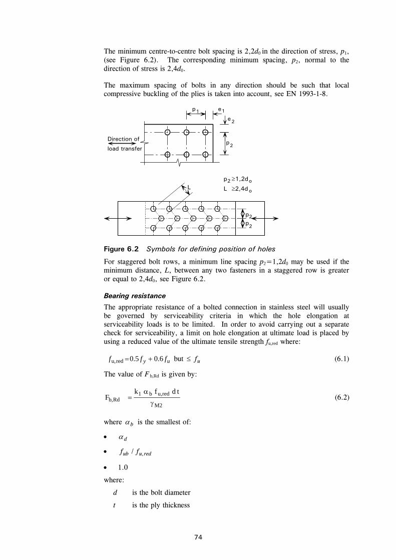
74
The minimum centre-to-centre bolt spacing is 2,2d0 in the direction of stress, p1, (see Figure 6.2). The corresponding minimum spacing, p2, normal to the direction of stress is 2,4d0.
The maximum spacing of bolts in any direction should be such that local compressive buckling of the plies is taken into account, see EN 1993-1-8.
p e
e
p
2
2Direction of
load transfer
11
2
2
2
p p
Lo
o
p 1,2d
L 2,4d
Figure 6.2 Symbols for defining position of holes
For staggered bolt rows, a minimum line spacing p2=1,2d0 may be used if the minimum distance, L, between any two fasteners in a staggered row is greater or equal to 2,4d0, see Figure 6.2.
Bearing resistance
The appropriate resistance of a bolted connection in stainless steel will usually be governed by serviceability criteria in which the hole elongation at serviceability loads is to be limited. In order to avoid carrying out a separate check for serviceability, a limit on hole elongation at ultimate load is placed by using a reduced value of the ultimate tensile strength fu,red where:
uy fff 6.05.0redu, but uf (6.1)
The value of F b,Rd is given by:
M2
redu,b1Rdb,
tdfkF
(6.2)
where b is the smallest of:
d
reduub ff ,/
1.0
where:
d is the bolt diameter
t is the ply thickness
75
fub is the characteristic ultimate tensile strength of the connected ply (taken as the minimum specified ultimate tensile strength, see Table 3.1).
01 3/ ded for end bolts in the direction of load transfer
4
1
3 0
1 d
pd for inner bolts in the direction of load transfer
1k is the smaller of 7,18,2 2 od
e or 2,5 for edge bolts perpendicular to the
direction of load transfer
1k is the smaller of 7,14,1 2 od
p or 2,5 for inner bolts perpendicular to the
direction of load transfer
In the case of single lap joints of flats with only one bolt row, the bolts should be provided with washers under both the head and the nut and the bearing resistance for each bolt should be further limited to:
M2
redu,Rdb,
5,1
tdf
F (6.3)
The resistance of a group of fasteners may be determined as the sum of the bearing resistances Fb,Rd of the individual fasteners provided that the design shear resistance Fv,Rd of each individual fastener is greater or equal to the design bearing resistance Fb,Rd. Otherwise the resistance of a group of fasteners should be determined by using the smallest resistance of the individual fasteners multiplied by the number of fasteners.
Tension resistance
The tensile resistance of the connected part should be based on the lesser of:
a) the plastic resistance of the gross cross-section
M0
yRdpl,
AfN (6.4)
b) the ultimate resistance of the net cross-section at holes for fasteners
M2
unetrRdu,
fAkN (6.5)
where the terms are defined in Section 4.7.2.
Note that the equation for the ultimate resistance of the net section should only be used for one shear plane when washers are present under both the head and nut of the bolt.
If ductile behaviour is required, then the plastic resistance of the gross section must be less than the net section ultimate resistance. Requirements for ductility

76
and rotation capacity are given in EN 1993-1-8. Requirements for seismic design are given in EN 1998.
Design for block tearing
The guidance in EN 1993-1-8 is applicable.
Angles connected by one leg and other unsymmetrically connected members in tension
The eccentricity of fasteners in end connections and the effects of the spacing and edge distances of the bolts should be taken into account in determining the design resistance of unsymmetrical members, as well as of symmetrical members that are connected unsymmetrically, such as angles connected by one leg.
Angles connected by a single row of bolts in one leg may be treated as concentrically loaded and the design ultimate resistance of the net section determined as follows:
With 1 bolt:
M2
u02Rdu,
5,00,2
ftdeN
(6.6)
With 2 bolts: M2
unet2Rdu,
fAN (6.7)
With three or more bolts: M2
unet3Rdu,
fAN (6.8)
where:
2 and 3 are reduction factors dependent on the pitch p1 as given in Table 6.1. For intermediate values of p1 the value of can be determined by linear interpolation.
Anet is the net area of the angle. For an unequal-leg angle connected by its smaller leg Anet should be taken as equal to the net section area of an equivalent equal-leg angle of leg size equal to that of the smaller leg.
Table 6.1 Reduction factors 2 and 3
Pitch, p1
Connection Factor 2,5d0 5,0d0
2 bolts 2 0,4 0,7
3 bolts or more 3 0,5 0,7
6.2.4 Fasteners Net areas
The area of the bolt to be used in calculations for bolts in tension should be taken as the tensile stress area, as defined in the appropriate product standard.
For bolts in shear, the greater shank area may be used if it can be guaranteed that the threaded portion will be excluded from the shear plane; consideration should be given to the possibility that bolts may be inserted from either
77
direction. If no such guarantee can be given, the tensile stress area should be used.
Shear resistance
The shear resistance of a bolted connection is dependent on the number of shear planes and their position along the bolt. For each shear plane, the shear resistance in the absence of tension may be determined as follows:
M2
ubRdv,
AfF (6.9)
where:
A is the gross cross-section area of the bolt (if the shear plane passes through unthreaded portion of the bolt); or the tensile stress area of the bolt (if the shear plane passes through the threaded portion of the bolt)
fub is the ultimate tensile strength of the bolt.
The value of may be defined in the National Annex. The recommended values are:
- if the shear plane passes through the unthreaded portion of the bolt, = 0,6
- if the shear plane passes through the threaded portion of the bolt, = 0,5.
Tensile resistance
The tension resistance of a bolt is given by Ft,Rd:
M2
sub2,
AfkF Rdt (6.10)
where:
k2 = 0,63 for countersunk bolts, otherwise k2 = 0,9.
Where fasteners are required to carry an applied tensile force, they should be proportioned to resist the additional force due to prying action, where this can occur. Guidance on accounting for prying forces is given in EN 1993-1-8.
Combined shear and tension
When a bolt is simultaneously subjected to a shear force, Fv,Ed, and a tensile force (including prying effects), Ft,Ed, interaction effects should be considered. This may be accounted for by satisfying the following interaction relationship:
0,14,1 Rdt,
Edt,
Rdv,
Edv, F
F
F
F (6.11)
where Fv,Rd and Ft,Rd are as given above. Note that the design tensile force (including any force due to prying action) must also be less than the tensile resistance.
78
Long joints and large grip lengths
For splices of unusual length (say 500 mm or 15 bolt diameters upwards) or when the grip length (i.e. the total thickness of the connected plies) exceeds 5 bolt diameters, the shear resistance should be reduced. In the absence of data for stainless steel, it is recommended to consult carbon steel rules for these situations in EN 1993-1-8.
6.3 Mechanical fasteners for thin gauge material The design of connections for stainless steel sheets using self-tapping screws can be calculated in accordance with EN 1993-1-3, except that the pull-out strength should be determined by testing. In order to avoid seizure of the screw or stripping its thread, the ability of the screw to drill and form threads in stainless steel should be demonstrated by tests unless sufficient experience is available. The reduced value for the tensile strength, fu,red, given in Equation 6.1, should be used in place of fu.
6.4 Welded connections 6.4.1 General It is essential that welds are made using correct procedures, including compatible consumables, with suitably qualified welders (see Section 10.4). This is important not only to ensure the strength of the weld and to achieve a defined weld profile but also to maintain corrosion resistance of the weld and surrounding material.
The following recommendations apply to full and partial penetration butt welds and to fillet welds made by an arc welding process such as:
Process Process number name
111 Metal-arc welding with covered electrode (manual metal arc welding)
121 Submerged arc welding with wire electrode
122 Submerged arc welding with strip electrode
131 Metal-arc inert gas welding (MIG welding)
135 Metal-arc active gas welding (MAG welding)
137 Flux-cored wire metal-arc welding with inert gas shield
141 Tungsten inert gas welding (TIG welding)
15 Plasma arc welding
(Process numbers are as defined in EN ISO 4063.)
Compatible consumables should be used, such that the weld yield strength and ultimate strengths exceed those of the parent material. (For undermatched consumables, see Section 6.4.4.) Table 6.2 gives suitable welding consumables for different grades and Table 6.3 gives the mechanical properties of these consumables.
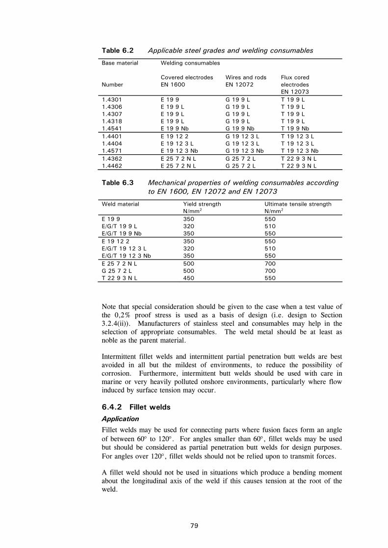
79
Table 6.2 Applicable steel grades and welding consumables
Base material Welding consumables
Number
Covered electrodes EN 1600
Wires and rods EN 12072
Flux cored electrodes EN 12073
1.4301 1.4306 1.4307 1.4318 1.4541
E 19 9 E 19 9 L E 19 9 L E 19 9 L E 19 9 Nb
G 19 9 L G 19 9 L G 19 9 L G 19 9 L G 19 9 Nb
T 19 9 L T 19 9 L T 19 9 L T 19 9 L T 19 9 Nb
1.4401 1.4404 1.4571
E 19 12 2 E 19 12 3 L E 19 12 3 Nb
G 19 12 3 L G 19 12 3 L G 19 12 3 Nb
T 19 12 3 L T 19 12 3 L T 19 12 3 Nb
1.4362 1.4462
E 25 7 2 N L E 25 7 2 N L
G 25 7 2 L G 25 7 2 L
T 22 9 3 N L T 22 9 3 N L
Table 6.3 Mechanical properties of welding consumables according
to EN 1600, EN 12072 and EN 12073
Weld material Yield strength N/mm2
Ultimate tensile strength N/mm2
E 19 9 E/G/T 19 9 L E/G/T 19 9 Nb
350 320 350
550 510 550
E 19 12 2 E/G/T 19 12 3 L E/G/T 19 12 3 Nb
350 320 350
550 510 550
E 25 7 2 N L G 25 7 2 L T 22 9 3 N L
500 500 450
700 700 550
Note that special consideration should be given to the case when a test value of the 0,2% proof stress is used as a basis of design (i.e. design to Section 3.2.4(ii)). Manufacturers of stainless steel and consumables may help in the selection of appropriate consumables. The weld metal should be at least as noble as the parent material.
Intermittent fillet welds and intermittent partial penetration butt welds are best avoided in all but the mildest of environments, to reduce the possibility of corrosion. Furthermore, intermittent butt welds should be used with care in marine or very heavily polluted onshore environments, particularly where flow induced by surface tension may occur.
6.4.2 Fillet welds Application
Fillet welds may be used for connecting parts where fusion faces form an angle of between 60 to 120. For angles smaller than 60, fillet welds may be used but should be considered as partial penetration butt welds for design purposes. For angles over 120, fillet welds should not be relied upon to transmit forces.
A fillet weld should not be used in situations which produce a bending moment about the longitudinal axis of the weld if this causes tension at the root of the weld.
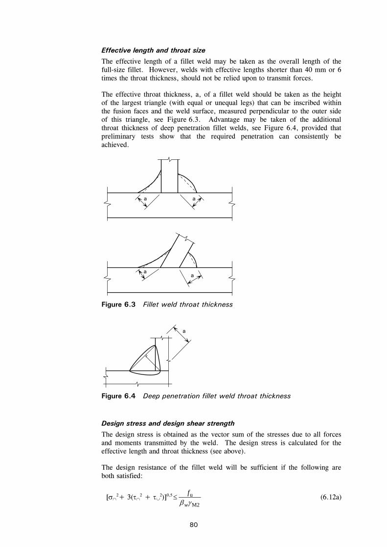
80
Effective length and throat size
The effective length of a fillet weld may be taken as the overall length of the full-size fillet. However, welds with effective lengths shorter than 40 mm or 6 times the throat thickness, should not be relied upon to transmit forces.
The effective throat thickness, a, of a fillet weld should be taken as the height of the largest triangle (with equal or unequal legs) that can be inscribed within the fusion faces and the weld surface, measured perpendicular to the outer side of this triangle, see Figure 6.3. Advantage may be taken of the additional throat thickness of deep penetration fillet welds, see Figure 6.4, provided that preliminary tests show that the required penetration can consistently be achieved.
Design stress and design shear strength
The design stress is obtained as the vector sum of the stresses due to all forces and moments transmitted by the weld. The design stress is calculated for the effective length and throat thickness (see above).
The design resistance of the fillet weld will be sufficient if the following are both satisfied:
[2+ 3(2 + 2)]0,5
M2
u
w
f (6.12a)
a
aa
a
Figure 6.3 Fillet weld throat thickness
a
Figure 6.4 Deep penetration fillet weld throat thickness
81
M2
u9,0
f (6.12b)
where:
is the normal stress perpendicular to the throat
is the shear stress (in the plane of the throat) perpendicular to the axis of the weld
is the shear stress (in the plane of the throat) parallel to the axis of the weld
fu is the nominal ultimate tensile strength of the weaker part joined
w is taken as 1,0 for all nominal strength classes of stainless steel, unless a lower value is justified by tests.
Alternatively, the Simplified method in 4.5.3.3 of EN 1993-1-8 can be used to calculate the design resistance of a fillet weld.
6.4.3 Butt welds Full penetration butt welds
The design resistance of a full penetration butt weld should be taken as equal to the design resistance of the weaker of the parts joined, provided that the weld satisfies the recommendations of Section 6.3.1.
Partial penetration butt welds
Partial penetration butt welds may be used to transmit shear forces. They are not recommended in situations where they would be subjected to tension.
The resistance of a partial penetration butt weld may be determined as for a deep penetration fillet weld. The throat thickness of a partial penetration butt weld may be taken as the depth of penetration that can be consistently achieved, as determined by procedure trials. In the absence of procedure trials, the throat thickness can be assumed to be the depth of preparation less 3 mm.
6.4.4 Welding cold worked stainless steel The same principles apply to welding cold worked stainless steel as to annealed stainless steel provided that:
The welded joint is subjected to axial load.
The cold worked strength level of the stainless steel does not exceed CP500 or C850.
Welding consumables are chosen according to Table 6.2.
The resistance of the base material in the heat affected zones is based on the tensile strength of the annealed base material.
The filler metal may have lower strength than the base material. For undermatched electrodes, the design resistance of fillet and butt welds should be based on the ultimate strength of the weld metal (see Table 6.3) with w taken as 1.0.
82
7 DESIGN FOR FIRE RESISTANCE
7.1 General This Section deals with the design of stainless steel structures that, for reasons of general fire safety, are required to fulfil certain functions, in terms of avoiding premature collapse of the structure (load bearing function), when exposed to fire. The recommendations are only concerned with passive methods of fire protection and are applicable to stainless steel grades and structures that are generally designed within the rules of Sections 1 to 6 of this document.
Austenitic stainless steels generally retain a higher proportion of their room temperature strength than carbon steels above temperatures of about 550 C, and a higher proportion of their stiffness at all temperatures.
EN 1991-1-2 gives the thermal and mechanical actions on structures exposed to fire. Fire is designated an accidental design situation in the Eurocodes. EN 1990 gives combinations of actions for accidental design situations, and recommends that the partial factors for actions are taken as 1,0. EN 1993-1-2 recommends that the partial material safety factor M,fi for the fire situation should be taken as 1,0.
The performance requirements of a stainless steel structure that may be subjected to accidental fire loading are no different to those of carbon steel, namely:
Where mechanical resistance in the case of fire is required, the structure should be designed and constructed in such a way that it maintains its load bearing function during the relevant fire exposure.
Deformation criteria should be applied where the means of fire protection, or the design criteria for separating elements, require the deformation of the load bearing structure to be considered. However, it is not necessary to consider the deformation of the load bearing structure if the fire resistance of the separating elements is based on the standard fire curve.
7.2 Mechanical properties at elevated temperatures
Table 7.1 gives strength and stiffness retention factors, relative to the appropriate value at 20 C, for the stress-strain relationship and the parameter g2, for grades of stainless steel at elevated temperatures. The factors are defined below:
k0,2proof, 0,2% proof strength at temperature relative to design strength at 20 C, i.e. yproof,0,2 ff
g2, a parameter used to calculate f2,, the strength at 2% total strain at temperature , using the following expression:
)( proof,2,0u,,2proof,2,02, ffgff (7.1)
ku, ultimate strength at temperature relative to ultimate strength at 20 C, i.e. uu, ff
83
kE, slope of linear elastic range at temperature relative to slope at 20C, i.e EE
where:
E is Young’s modulus at 20°C (= 200 000 N/mm2)
fy is the characteristic yield strength at 20°C, as defined in Section 3.2.4
fu is the characteristic ultimate tensile strength at 20°C, as defined in Section 3.2.4.
In determining the structural fire resistance of stainless steel members, the following characteristic material strength should be used:
Columns f0,2proof, (all cross-section Classes)
Restrained beams f2, (Class 1-3 cross-sections)
f0,2proof, (Class 4 cross-sections)
Unrestrained beams f0,2proof, (all cross-section Classes)
Tension members f2, (all cross-section Classes).
For Class 1-3 restrained beams and tension members, in situations which require consideration of the deformation criteria, the strength at a total strain of 1,0%, f1, is recommended as a basis for the calculations instead of f2,. The value of f1,should be calculated using the following relationship:
)(5,0 0,2proof,u,2,0,2proof,1, ffgff (7.2)
Values for f0,2proof, are given relative to the characteristic yield strength at 20 C by the factor k0,2proof, in Table 7.1.

84
Table 7.1 Retention factors for strength and stiffness and parameter g2, at elevated temperature
Temperature (°C)
Retention factor k0,2proof,
Parameter g2,
Retention factor ku,
Retention factor kE,
Grade 1.4301 20 1,00 0,26 1,00 1,00 100 0,82 0,24 0,87 0,96 200 0,68 0,19 0,77 0,92 300 0,64 0,19 0,73 0,88 400 0,60 0,19 0,72 0,84 500 0,54 0,19 0,67 0,80 600 0,49 0,22 0,58 0,76 700 0,40 0,26 0,43 0,71 800 0,27 0,35 0,27 0,63 900 0,14 0,38 0,15 0,45 1000 0,06 0,40 0,07 0,20 1100 0,03 0,40 0,03 0,10 1200 0,00 0,40 0,00 0,00
Grade 1.4401 20 1,00 0,24 1,00 1,00 100 0,88 0,24 0,93 0,96 200 0,76 0,24 0,87 0,92 300 0,71 0,24 0,84 0,88 400 0,66 0,21 0,83 0,84 500 0,63 0,20 0,79 0,80 600 0,61 0,19 0,72 0,76 700 0,51 0,24 0,55 0,71 800 0,40 0,35 0,34 0,63 900 0,19 0,38 0,18 0,45 1000 0,10 0,40 0,09 0,20 1100 0,05 0,40 0,04 0,10 1200 0,00 0,40 0,00 0,00
Grade 1.4571 20 1,00 0,25 1,00 1,00 100 0,89 0,25 0,88 0,96 200 0,83 0,25 0,81 0,92 300 0,77 0,24 0,80 0,88 400 0,72 0,22 0,80 0,84 500 0,69 0,21 0,77 0,80 600 0,66 0,21 0,71 0,76 700 0,59 0,25 0,57 0,71 800 0,50 0,35 0,38 0,63 900 0,28 0,38 0,22 0,45 1000 0,15 0,40 0,11 0,20 1100 0,075 0,40 0,055 0,10 1200 0,00 0,40 0,00 0,00
Grade 1.4462 20 1,00 0,35 1,00 1,00 100 0,91 0,35 0,93 0,96 200 0,80 0,32 0,85 0,92 300 0,75 0,30 0,83 0,88 400 0,72 0,28 0,82 0,84 500 0,65 0,30 0,71 0,80 600 0,56 0,33 0,57 0,76 700 0,37 0,40 0,38 0,71 800 0,26 0,41 0,29 0,63 900 0,10 0,45 0,12 0,45 1000 0,03 0,47 0,04 0,20 1100 0,015 0,47 0,02 0,10 1200 0,00 0,47 0,00 0,00
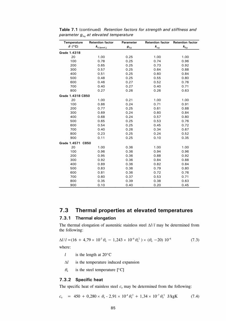
85
Table 7.1 (continued) Retention factors for strength and stiffness and parameter g2, at elevated temperature
Temperature (°C)
Retention factor k0,2proof,
Parameter g2,
Retention factor ku,
Retention factor kE,
Grade 1.4318 20 1.00 0.25 1.00 1.00 100 0.78 0.25 0.74 0.96 200 0.65 0.25 0.73 0.92 300 0.57 0.25 0.64 0.88 400 0.51 0.25 0.60 0.84 500 0.48 0.25 0.55 0.80 600 0.46 0.27 0.52 0.76 700 0.40 0.27 0.40 0.71 800 0.27 0.26 0.26 0.63
Grade 1.4318 C850 20 1.00 0.21 1.00 1.00 100 0.86 0.24 0.71 0.91 200 0.77 0.25 0.61 0.88 300 0.69 0.24 0.60 0.84 400 0.68 0.24 0.57 0.80 500 0.65 0.25 0.53 0.76 600 0.54 0.25 0.45 0.72 700 0.40 0.26 0.34 0.67 800 0.23 0.25 0.24 0.52 900 0.11 0.25 0.10 0.35
Grade 1.4571 C850 20 1.00 0.36 1.00 1.00 100 0.96 0.36 0.94 0.96 200 0.95 0.36 0.88 0.92 300 0.92 0.36 0.84 0.88 400 0.89 0.36 0.82 0.84 500 0.83 0.36 0.79 0.80 600 0.81 0.36 0.72 0.76 700 0.60 0.37 0.53 0.71 800 0.35 0.39 0.38 0.63 900 0.10 0.40 0.20 0.45
7.3 Thermal properties at elevated temperatures 7.3.1 Thermal elongation
The thermal elongation of austenitic stainless steel l / l may be determined from the following:
l / l =(16 + 4,79 10-3 a − 1,243 10–6 a2 ) (a −20) 10–6 (7.3)
where:
l is the length at 20 C
l is the temperature induced expansion
a is the steel temperature [C]
7.3.2 Specific heat The specific heat of stainless steel ca may be determined from the following:
ca = 450 + 0,280 a - 2,91 10-4 a2 + 1,34 10–7 a
3 J/kgK (7.4)

86
where:
a is defined in Section 7.3.1
7.3.3 Thermal conductivity
The thermal conductivity of stainless steel a may be determined from the following:
a = 14,6 + 1,27 10–2 a W/mK (7.5)
where:
a is defined in Section 7.3.1.
7.4 Determination of structural fire resistance Fire resistance may be determined by one or more of the following approaches:
simple calculation method applied to individual members
advanced calculation method
testing.
The simple calculation method is based on conservative assumptions. Advanced calculation methods are design methods in which engineering principles are applied in a realistic manner to specific applications. Where no simple calculation model is given, it is necessary to use either a design method based on an advanced calculation model or a method based on test results.
Advanced calculation methods are covered in the Commentary to these Recommendations (see Foreword).
7.4.1 Cross section classification In fire design, the method of classification of cross-sections described in Section 4 of this document should be adopted, using design properties at 20°C.
7.4.2 Tension members
The design resistance Nfi,,Rd of a tension member at a uniform temperature a should be determined from:
Nfi,,Rd = k2, NRd [M0 / M,fi ] (7.6)
where:
k2, yff /,2 i.e. the retention factor for the strength at 2% total strain at
temperature a
NRd is the design resistance of the cross-section Npl,Rd for normal temperature design, according to Section 4.7.2.
M0 and M,fi are partial factors, see Table 2.1
Where the temperature in the member is non-uniform, the design resistance is given by:
87
Nfi,t,Rd =
n
i
fkA1
fiM,yi,,2i / (7.7)
where:
Ai is an elemental area of the cross-section
i is the temperature in the elemental area Ai
k2,,i is the retention factor for the strength at 2% total strain at temperature i (see Section 7.2).
Alternatively, the design resistance Nfi,t,Rd at time t of a tension member with a non-uniform temperature distribution may conservatively be taken as equal to the design resistance Nfi,,Rd of a tension member with a uniform temperature a equal to the maximum temperature a,max reached at time t .
7.4.3 Compression members The following recommendations apply to columns with Class 1, 2 ,3 or 4 cross-sections that are:
cold formed, open cross-sections (not welded), e.g. channels or angles, or
cold formed hollow cross-sections (both seam welded or seamless), e.g. circular or rectangular hollow sections.
The design buckling resistance Nb,fi,t,Rd at time t of a compression member with a uniform temperature a is given by:
Nb,fi,t,Rd = fi A k0,2proof, fy / M,fi for Class 1, 2 or 3 sections (7.8)
Nb,fi,t,Rd = fi Aeff k0,2proof, fy / M,fi for Class 4 sections (7.9)
where:
k0,2proof, is the 0,2% proof strength retention factor at temperature a (see Section 7.2).
fi is the reduction factor for flexural buckling in fire, given by:
22fi
1
but 1fi (7.10)
where: 2015,0 (7.11)
in which and 0 are the room temperature buckling coefficients given in Table 5.1.
The modified non-dimensional slenderness θ at temperature is given by:
5,0
,E
,proof2,0
θ
θ
k
k for all Classes of cross-section (7.12)

88
where:
kE, is the retention factor for the slope of the linear elastic range at temperature a (see Section 7.2).
Where the temperature of the member is non-uniform, the compression resistance may conservatively be estimated by assuming a uniform temperature that is equal to the maximum temperature in the member.
The buckling length lfi of a column for fire design should generally be determined as for normal temperature design. However, in a braced frame, the buckling length lfi may be determined by considering the column as fixed in direction at continuous or semi-continuous connections to the column lengths in the fire compartments above and below. This assumption can only be made if the fire resistance of the building components that separate these fire compartments is not less than the fire resistance of the column.
In the case of a braced frame in which each storey comprises a separate fire compartment with sufficient fire resistance, the buckling length of a column in an intermediate storey is given by lfi = 0,5L and in the top storey the buckling length is given by lfi = 0,7L , where L is the system length in the relevant storey, see Figure 7.1.
4
Shear wall orother bracingsystem
Separate firecompartmentsin each storey
Buckling lengthof the columnexposed to fire
L 4
L
L
L
3
2
1
2
Deformationmode in fire
fi,4 = 0,7L
fi,2 = 0,5L
Buckling lengthof the columnexposed to fire
Figure 7.1 Buckling lengths lfi of columns in braced frames 7.4.4 Laterally restrained beams
The design moment resistance Mfi,,Rd of a cross-section at a uniform temperature a should be determined from:
Mfi,,Rd = k2, [M0 / M,fi ] MRd for Class 1, 2 or 3 cross-sections (7.13)
Mfi,,Rd = k0,2proof, [M0 / M,fi ] MRd for Class 4 cross-sections (7.14)
where:
MRd is the design plastic moment resistance of the gross cross-section Mpl,Rd
(Class 1 or 2 cross-sections), the elastic moment resistance of the gross cross-section Mel,Rd (Class 3 cross-sections) or effective moment resistance of the effective cross section Meff,Rd (Class 4 cross-sections) for normal temperature design
k2,and k0,2proof, are as defined in Section 7.4.3.
89
Where it is necessary to allow for the effects of shear, the reduced moment resistance for normal temperature design according to Section 4.7.6 should be used.
The design moment resistance Mfi,t,Rd at time t of a cross-section in a member with a non-uniform temperature distribution, may conservatively be determined from:
Mfi,t,Rd = Mfi,,Rd / 1 2 (7.15)
where:
Mfi,,Rd is the design moment resistance of the cross-section (or effective cross section for Class 4 cross-section) at a uniform temperature a equal to the maximum temperature in the cross-section
1 is an adaptation factor for non-uniform temperature across the cross-section, see Table 7.2
2 is an adaptation factor for non-uniform temperature along the beam, see Table 7.2.
Table 7.2 Adaptation factors
Exposure condition 1
for a beam exposed to fire on all four sides 1,0
for an unprotected beam exposed to fire on three sides, with a composite or concrete slab on its fourth side
0,70
for a protected beam exposed to fire on three sides, with a composite or concrete slab on its fourth side
0,85
2
at the supports of a statically indeterminate beam 0,85
in all other cases 1,0
The design shear resistance Vfi,t,Rd at time t of a cross-section with a non-uniform temperature distribution should be determined from:
Vfi,t,Rd= k2,web VRd [M0 / M,fi ] for Class 1, 2 or 3 cross-sections (7.16)
Vfi,t,Rd= k0,2proof,web VRd [M0 / M,fi ] for Class 4 cross-sections (7.17)
where:
VRd is the shear resistance of the gross cross-section for normal temperature design, according to Section 4.7.5 (for temperatures above 400C, should be taken as 1,0).
web is the temperature in the web of the section.
7.4.5 Laterally unrestrained beams The design buckling resistance moment Mb,fi,t,Rd at time t of a laterally unrestrained beam should be determined from:
Mb,fi,t,Rd = LT,fi Wpl,y k0,2proof, fy / M,fi for Class 1 and 2 sections (7.18)
Mb,fi,t,Rd = LT,fi Wel,y k0,2proof,fy / M,fi for Class 3 sections (7.19)
Mb,fi,t,Rd = LT,fi Weff,y k0,2proof, fy / M,fi for Class 4 sections (7.20)
90
where:
LT,fi is the reduction factor for lateral-torsional buckling in fire, given by:
2
LT,2
LT,LT,
fiLT,1
but 1fiLT, (7.21)
and 2,LT,LTLT,LT 4,015,0 (7.22)
in which LT is the room temperature imperfection factor given in Section 5.4.2.
k0,2proof, is the retention factor defined in Section 7.4.3 at the maximum temperature reached anywhere in the section.
The non-dimensional slenderness LT, at temperature is given by:
5,0
E,
proof,2,0LTLT
k
k, for all Classes of cross-section (7.23)
where:
kE, is the reduction factor defined in Section 7.4.3 at temperature .
7.4.6 Members subject to axial compression and bending The combined effects of compressive loads and bending moments should be checked in accordance with the following expressions to prevent premature major and minor axis buckling and lateral torsional buckling:
a) For Class 1, 2 or 3 cross-sections
1Rd,fi,z,
Edfi,z,z
Rd,fi,y,
Edfi,y,y
fiM,
y0,2proof,fimin,
Edfi,
M
Mk
M
Mk
fkA
N
(7.24)
1Rd,fi,z,
Edfi,z,z
Rd,fi,y,fiLT,
Edfi,y,LT
fiM,
y0,2proof,fimin1,
Edfi,
M
Mk
M
Mk
fkA
N
(7.25)
where:
Nfi,Ed, My,fi,Ed and Mz,fi,Ed are the axial design load and bending moments for the fire situation
My,fi,,Rd and Mz,fi,,Rd are as defined in Section 7.4.4
k0,2proof, is the reduction factor at temperature as defined in Section 7.4.3
min,fi is the smallest reduction factor for flexural, torsional and torsional-flexural buckling at temperature as defined in Section 7.4.3
min1,fi is the smallest reduction factor for flexural buckling about the z axis, torsional and torsional-flexural buckling at temperature as defined in Section 7.4.3
LT,fi is the reduction factor for lateral torsional buckling at temperature as defined in Section 7.4.5.
91
11
fiM,
yθ0,2proof,fiz,
Edfi,LT
f
kA
NkLT (7.26)
9,015,015,0 LTM,z,LT (7.27)
31
fiM,
yθ0,2proof,fiy,
Edfi,y
f
kA
Nky (7.28)
8,029,044,032,1 yM,y,yM,y (7.29)
31
fiM,
yθ0,2proof,fiz,
Edfi,z
f
kA
Nkz (7.30)
8,029,044,052 zM,z,zM, z and 1,1z, (7.31)
M is an equivalent uniform moment factor, given in Table 7.3.
b) For Class 4 cross-sections:
1Rd,fi,z,
Edfi,Edfi,z,z
Rd,fi,y,
Edfi,Edfi,y,y
fiM,
y0,2proof,efffimin,
Edfi,
M
eNMk
M
eNMk
fkA
N zy
(7.32)
1Rd,fi,z,
Edi,Edfi,z,z
Rd,fi,y,fiLT,
Edfi,Edfi,y,LT
fiM,
y0,2proof,efffimin1,
Edfi,
M
eNMk
M
eNMk
fkA
N zfy
(7.33)
where the terms are defined in (a) above except that in the calculation of ky, kz and kLT, A should be replaced by Aeff.
92
Table 7.3 Equivalent uniform moment factors, M
Moment diagram Equivalent uniform moment factor M
End moments
MM1
1 -1 1
M, = 1,8 – 0,7
Moments due to in-plane lateral loads
MQ
MQ
M,Q = 1,3 M,Q = 1,4
Moments due to in-plane lateral loads plus end moments
M1
MQ
M
,,, MQMQ
MM MM
M1 M
MQ
MQ = max M due to lateral load only
M1 M
MQ
M1 M
MQ
For moment diagram without change of sign: M =max M For moment diagram with change of sign: M = max M+ min M
7.4.7 Calculation of temperature rise in stainless steel The method for calculating the temperature rise in carbon steel can also be applied to stainless steel.
The incremental rise in temperature of a uniformly heated bare stainless steel section in time interval t is given by:
thc
VA
dnet,
aa
mta,
(7.34)
where:
ca is the specific heat of stainless steel, (J/kgK), as given in Section 7.3.2
a is the density of stainless steel (kg/m3), as given in Table 3.6 (usually considered as temperature independent)
Am/V is the section factor for unprotected steel members
93
Am is the surface area of the member per unit length
V is the volume of the member per unit length
dnet,h is the design value of the net heat flux per unit area
= rnet,cnet, hh (7.35)
in which:
cnet,h = agc (7.36)
rnet,h = 4a
4g
8res 2732731067,5 (7.37)
c is the coefficient of heat transfer by convection (usually taken as 25W/m2K)
g is the gas temperature of the environment of the member in fire exposure (C), given by the nominal temperature-time curve
a is the temperature of the steel section which is assumed to be uniform at time t (C)
is the configuration factor
res is the resultant emissivity.
The parameter res represents the radiation transmitted between the fire and the stainless steel surface and its magnitude depends on the degree of direct exposure of the element to the fire. Elements which are partially shielded from the radiant effects of the heat of the fire would have a lower value of res. For stainless steel, res can be taken as 0,2.
The above equation for the incremental temperature rise may be used to determine steel temperatures by incremental integration, if the variation of the fire temperature with time is known. The nominal temperature-time curve for a cellulosic fire is given in EN 1991-1-2 as:
g = 20+345log10(8t+1) (7.38)
where:
t is the elapsed time (minutes).
94
8 FATIGUE
Consideration should be given to metal fatigue in structures or parts of structures subjected to significant levels of repeated stress. No fatigue assessment is normally required for building structures, except for members supporting lifting appliances, rolling loads or vibrating machinery, and for members subject to wind-induced oscillation.
In common with carbon steel structures, the combination of stress concentrations and defects at welded joints leads to these locations being almost invariably more prone to fatigue failure than other parts of the structure. Guidance on estimating the fatigue strength of carbon steel structures is applicable to stainless steels (see EN 1993-1-9).
Much can be done to reduce the susceptibility of a structure to fatigue by adopting good design practice. This involves judiciously selecting the overall structural configuration and carefully choosing constructional details that are fatigue resistant. The key to fatigue resistant design is a rational consideration of fatigue early in the design process. A fatigue assessment performed only after other design criteria have been satisfied may result in an inadequate or costly structure. It is also important to consider the needs of the fabricator and erector. It is therefore recommended that early consultations be held with them to point out areas of the structure which are most sensitive to fatigue cracking, to discuss special precautions and to become aware of fabrication and erection problems. In particular, the use of holes or lifting attachments to ease fabrication or erection should be considered during the fatigue evaluation.
It may be possible to eliminate potential fatigue problems by giving due regard to constructional details and avoiding:
sharp changes in cross-section and stress concentrations in general
misalignments and eccentricities
small discontinuities such as scratches and grinding marks
unnecessary welding of secondary attachments, e.g. lifting lugs
partial penetration welds, fillet welds, intermittent welding, and backing strips
arc strikes.
Although weld improvement techniques such as weld profile control, weld toe grinding, and shot and hammer peening may improve the fatigue strength of a joint, there are insufficient data to quantify the possible benefits for stainless steel. It should also be noted that the techniques are all labour-intensive and require skill and experience of the operator to achieve maximum benefit. They should not, except in special cases, be seen as a design option.
95
9 TESTING
9.1 General Testing of stainless steel materials and members may be required for a number of reasons:
If the design is to be based on actual material data (see Section 3.2.4).
If advantage is to be taken of the strength enhancement of cold formed corners in members (see Sections 3.2.2 and 4.7.1).
If the geometry of a member is such that it lies outside applicable limits (such as those given in Section 4.2).
If a number of structures or components are to be based on prototype testing.
If confirmation of consistency of production is required.
The usual precautions and requirements for test procedures and results evaluation appertaining to carbon steel testing also apply to stainless steel testing. It is therefore generally recommended that such requirements are consulted, e.g. see Section 5.2 and Annex D of EN 1990 and Section 9 and Annex A of EN 1993-1-3. However, there are particular aspects of the behaviour of stainless steels which need to be given more thought in the design of the tests than perhaps would be the case for carbon steels. The following brief guidance is offered.
9.2 Stress-strain curve determination The applicable European Standard for material tests is EN 10002-1 Tensile testing of metallic materials. Method of test at ambient temperature. This standard does not give end details for the test coupons, although the diagrams suggest that the ends would be gripped. However, it is recommended that loading should be accomplished by pins passing through the ends of the coupon which are of sufficient area to sustain the shear. This is to ensure the coupon is axially loaded, thus enabling the actual shape of the stress-strain curve to be discerned without any spurious effect caused by premature yielding due to load eccentricity. Axiallity of loading may be confirmed by elastic tests with an extensometer placed at various orientations about the specimen.
Cognisance should be taken of strain-rate effects, see Section 3.2.2.
9.3 Tests on members It is recommended that member tests should be full scale or as near to full scale as possible, depending on test facilities, and that the specimens should be manufactured by the same fabrication processes to be used in the final structure. If the components are welded, the prototype should be welded in the same way.
Since stainless steel may exhibit anisotropy, it is recommended that the specimens are prepared from the plate or sheet in the same orientation (i.e. transverse or parallel to the rolling direction) as intended for the final structure.
96
If the final orientation is unknown or cannot be guaranteed, it may be necessary to conduct tests for both orientations and take the less favourable set of results.
Stainless steel displays higher ductility and greater strain hardening than carbon steel and therefore the test rig capabilities may need to be greater than those required for testing carbon steel members of equivalent material yield strength. This not only applies to rig loading capacity but also to the ability of the rig to allow greater deformation of the specimen.
It should be noted that at higher specimen loads, the effects of creep become more manifest and this may mean that strain or displacement readings do not stabilise within a reasonable time.
For work hardened materials, both the tensile and compressive strength should be determined in the direction in question. Evaluation of the test results should be carried out with the relevant strength as reference.

97
10 FABRICATION ASPECTS
10.1 Introduction The purpose of this Section is to highlight relevant aspects of stainless steel fabrication for the design engineer, including recommendations for good practice. It also allows a preliminary assessment to be made of the suitability of a fabricator to perform the work.
Stainless steel is not a difficult material to work with. However, in some respects it is different from carbon steel and should be treated accordingly. Many fabrication and joining processes are similar to those used for carbon steel, but the different characteristics of stainless steel require special attention in a number of areas. It is important that effective communication is established between the designer and fabricator early in the project to ensure that appropriate fabrication practices can and will be adopted.
An overriding objective is to maintain the steel's corrosion resistance. It is essential that precautions are taken at all stages of storing, handling and forming to minimise influences that jeopardise the formation of the self-repairing passive layer. Special care must be taken to restore the full corrosion resistance of the welded zone. Although essential, the precautions are simple and, in general, are matters of good engineering practice.
It is important to preserve the good surface appearance of stainless steel throughout fabrication. Not only are surface blemishes unsightly, but they are usually unacceptable and prove time-consuming and expensive to correct. Whereas surface blemishes will normally be hidden by paint in carbon steel structures, this will only rarely be the case for stainless steel structures.
The structural form may be dictated by the availability of materials. It should be recognised that the available range of hot rolled stainless steel sections is more limited than for carbon steel. This results in a greater use of cold formed and welded members than is normally encountered. Also, because of brake press length capabilities, only relatively short lengths can be formed, which leads to an increased use of splices. In detailing joints, consideration should be given to clearances for bolts near bend radii and to potential fit up problems arising from weld distortion.
The guidance on fabrication and erection is in accordance with ENV 1090-6 Execution of steel structures. Supplementary rules for stainless steel. This standard is currently being converted into EN 1090 Execution of steel structures and aluminium structures. EN 1090-1 will give rules for using CE marks on steel structures. EN 1090-2 will include execution classes dependent on the type of steel structure; specific fabrication and erection requirements will correspond to the different execution classes. It is expected that EN 1090-2 will be submitted for final vote at the beginning of 2007.
The relevant standard for welding stainless steels is EN 1011-3 Welding. Recommendations for welding of metallic materials. Arc welding of stainless steels.
98
10.2 Storage and handling Generally, greater care is required in storing and handling stainless steel than carbon steel to avoid damaging the surface finish (especially for bright annealed or polished finishes) and to avoid contamination by carbon steel and iron. Storage and handling procedures should be agreed between the relevant parties to the contract in advance of any fabrication and in sufficient detail to accommodate any special requirements. The procedures should cover, for instance, the following items:
The steel should be inspected immediately after delivery for any surface damage.
The steel may have a protective plastic or other coating. This should be left on as long as possible, removing it just before final fabrication. The protective covering should be called for in the procurement document if it is required (e.g. for bright annealed finishes).
Storage in salt-laden humid atmospheres should be avoided. Storage racks should not have carbon steel rubbing surfaces and should, therefore, be protected by wooden, rubber or plastic battens or sheaths. Sheets and plates should preferably be stacked vertically; horizontally stacked sheets may get walked on with a risk of iron contamination and surface damage.
Carbon steel lifting tackle, e.g. chains, hooks, and cleats should be avoided. Again, the use of isolating materials, or the use of suction cups, will prevent iron pick-up. The forks of fork lift trucks should also be protected.
Contact with chemicals including undue amounts of oils and greases (which may stain some finishes) should be avoided.
Ideally, segregated fabrication areas for carbon steel and stainless steel should be used. Only tools dedicated to stainless steel should be employed (this particularly applies to grinding wheels and wire brushes). Note that wire brushes and wire wool should be of stainless steel and generally in a grade that is equivalent in terms of corrosion resistance (e.g. do not use ferritic stainless steel brushes on austenitic stainless steel).
As a precaution during fabrication and erection, it is advisable to ensure that any sharp burrs formed during shearing operations are removed.
Consideration should be given to any requirements needed in protecting the finished fabrication during transportation.
10.3 Shaping operations Austenitic stainless steels work harden significantly during cold working. This can be both a useful property, enabling extensive forming during stretch forming without risk of premature fracture, and a disadvantage, especially during machining when special attention to cutting feeds and speeds is required. The rate of work hardening differs with different grades, for example grade 1.4318 work hardens at a greater rate than other grades used in construction applications.
10.3.1 Cutting Stainless steel is a relatively expensive material compared to some other metals and care is needed in marking out plates and sheets to avoid wastage in cutting.
99
Note that more wastage may result if the material has a polishing grain (or a unidirectional pattern) which has to be maintained in the fabrication. Some marking pens/crayons will prove difficult to remove, or cause staining, if used directly on the surface (rather than on any protective film); checks should be made that markers are satisfactory.
Stainless steel may be cut using usual methods, e.g. shearing and sawing, but power requirements will be greater than those for similar thicknesses of carbon steel, due to work hardening. If possible, cutting (and machining in general) should be carried out when the metal is in the annealed (softened) state, to limit work hardening and tool wear.
For cutting straight lines, guillotine shearing is widely used. By using open ended guillotines, a continuous cut greater in length than the shear blades can be achieved, although at the risk of introducing small steps in the cut edge.
Plasma arc techniques are also used and are particularly useful for cutting thick plates and profiles and where the cut edges are to be machined, e.g. for weld preparation. Oxyacetylene cutting is not satisfactory for cutting stainless steel, unless a powder fluxing technique is used.
10.3.2 Cold forming Stainless steel is readily shaped by commonly used cold forming techniques such as bending, spinning, pressing and deep drawing. For structural applications press brake bending is the most relevant technique though, for high volume thin gauge products, roll forming may be more economic.
Again, the power requirement for bending stainless steel will be higher than for bending carbon steel due to work hardening (by about 50% in the case of the austentic stainless steels or more in the case of duplex grades). Also, stainless steel has to be overbent to a slightly higher degree than carbon steel to counteract the effects of springback. For complex cross-sections, it is prudent to involve the fabricator as early as possible in the design.
Stainless steel's high ductility allows small radii to be formed, perhaps as low as half the thickness in annealed materials. However, it is generally recommended to adopt the following internal radii as minima:
2t for austenitic grades
2,5t for duplex grades
where t is the thickness of the material.
When bending tubulars, the following guidance may be given:
the outer tube diameter to wall thickness ratio should not exceed 15 (to avoid costly tooling).
the bend radius (to centreline of tube) should not be less than 2,5d where d is the outer diameter
any welding bead should be positioned close to the neutral axis to reduce the bending stresses at the weld.
10.3.3 Holes Holes may be drilled or punched. In drilling, positive cutting must be maintained to avoid work hardening and this requires sharp bits with correct
100
angles of rake and correct cutting speeds. The use of a round tipped centre punch is not recommended as this work hardens the surface. Either a centre drill should be used or if a centre punch has to be used, it should be of the triangular pointed type. Punched holes can be made in austenitic stainless steel up to about 20 mm in thickness; the higher strength of duplex grades leads to a smaller limiting thickness. The minimum diameter of hole that can be punched out is 2 mm greater than the sheet thickness. Punched holes should be avoided in corrosive environments, due to the presence of the work hardened edge.
10.4 Welding 10.4.1 Introduction The welding of austenitic and duplex stainless steels is widely and successfully carried out using normal processes, provided that suitable consumables are used. General cleanliness and the absence of contamination are important for attaining good weld quality. Oils or other hydrocarbons and wax crayon marks should be removed, to avoid their decomposition and the risk of carbon pick-up. The weld should be free from zinc, including that arising from galvanised products, and from copper and its alloys. (Care needs to be taken when copper backing bars are used; a groove should be provided in the bar immediately adjacent to the fusion area.)
It is more important in stainless steel than carbon steel to reduce sites at which crevice corrosion (see Section 3.7.2) may initiate. Welding deficiencies such as undercut, lack of penetration, weld spatter, slag and stray arc strikes are all potential sites and should thus be minimised. Stray arc strikes or arcing at loose earth connections also damage the passive layer, and possibly give rise to preferential corrosion, thereby ruining the appearance of a fabrication.
Where the weld appearance is important, the engineer should specify the as-welded profile and surface condition required. This may influence the welding process selected or the post weld treatment. Consideration should also be given to the location of the weld; is it possible to apply the appropriate post weld treatment?
Heat input and interpass temperatures need to be controlled to minimise distortion (see Section 10.4.4) and to avoid potential metallurgical problems (see Section 10.4.5).
Welding should be carried out to an approved welding procedure according to a standard such as EN ISO 15609-1 Specification and qualification of welding procedures for metallic materials. Welding procedure specification. Arc welding. Welders should be approved in accordance with EN 287-1 Qualification test of welders. Fusion welding. Steels. Welding procedures contain the following elements:
verification of the welding method by detailing the derivation and testing requirements of weld procedures
the qualifications of welders
the control of welding operations during preparation, actual welding and post-weld treatment
the level of inspection and non-destructive testing techniques to be applied
101
the acceptance criteria for the permitted level of weld defects.
Provided that suitable procedures are followed, welding problems should not occur. However, the engineer should be aware that welding distortion is generally greater in stainless steel than in carbon steel, see Section 10.4.4.
Lock welding of the nut to the bolt should never be allowed, as the materials are formulated for strength and not for fusion welding.
10.4.2 Processes As mentioned above, the common fusion methods of welding can be used on stainless steel. Table 10.1 shows the suitability of various processes for thickness ranges, etc. In MIG or TIG welding, the shielding gas should not contain carbon dioxide due to the possibility of decomposition leading to carbon pick-up and, in the case of duplex grades, nitrogen should be also avoided.
Table 10.1 Welding processes and their suitability
Weld process (EN ISO 4063)
Suitable product forms
Types of welded joint
Material thickness range
Weld positions
Suitable shop/site conditions
111 Metal arc welding with covered electrode (Manual metal arc)
All but not sheet
All 3 mm(1) or greater
All All
131 Metal arc inert gas (MIG)
All All 2 mm(1) or greater
All All(2)
141 Tungsten inert gas (TIG)
All All Up to 10 mm maximum
All All(2)
121/122 Submerged arc welding
All but not sheet
All 3 mm(1) or greater
Downhand positions only
All
2 Resistance welding Sheet only
All 3 mm maximum approximate
All All
Notes:
1) Depends upon type of weld joint used.
2) More sensitive to weather than other processes and better environmental protection is required.
10.4.3 Consumables Commercial consumables have been formulated to give weld deposits of equivalent strength and corrosion resistance to the parent metal and to minimise the risk of solidification cracking. For specialist applications, such as unusually aggressive environments or where non-magnetic properties are required, the advice of steel producers and manufacturers of consumables should be sought. All consumables should be kept free from contaminants and stored according to the manufacturer's instructions.
All welding consumables should conform to the requirements specified in ENV 1090 (to be superseded by EN 1090-2). It is important that consumables are kept free from contaminants and stored according to the manufacturer’s instructions.
102
10.4.4 Welding distortion In common with other metals, stainless steel suffers from distortion due to welding. The types of distortion (angular, bowing, shrinkage etc.) are similar in nature to those found in carbon steel structures. However, the distortion of stainless steel, particularly of austenitic grades, is greater than that of carbon steel because of higher coefficients of thermal expansion and lower thermal conductivities (which lead to steeper temperature gradients), see Section 3.3.
Welding distortion can only be controlled, not eliminated. The following actions may be taken by the designer and the fabricator:
Designer actions Remove the necessity to weld.
Reduce the extent of welding.
Reduce the area of welds. For instance in thick sections, specify double V, U or double U preparations in preference to single V.
Use symmetrical joints.
Design to accommodate wider dimensional tolerances.
Fabricator actions Use efficient clamping jigs. If possible the jig should incorporate copper or
aluminium bars to help conduct heat away from the weld area.
When efficient jigging is not possible, use closely spaced tack welds laid in a balanced sequence.
Ensure that good fit up and alignment is obtained prior to welding.
Use the lowest heat input commensurate with the selected weld process.
Use balanced welding and appropriate sequences (e.g. backstepping and block sequences).
10.4.5 Metallurgical considerations It is not possible to cover here the metallurgy of stainless steels except for some of the more significant factors.
Formation of precipitates in the austenitic grades
In the austenitic steels, the heat affected zone is relatively tolerant to grain growth and to the precipitation of brittle and intermetallic phases. Welding procedures are usually designed to control the time spent in the critical temperature range for precipitation effects (450 - 900°C). Excessive weld repair naturally increases the time spent and is thus usually restricted to three major repairs.
The formation of chromium carbide precipitates, and the ensuing loss of corrosion resistance, is discussed in Section 3.7.2 Intergranular corrosion where it is noted that this is not normally a problem with the low carbon grades of austenitic stainless steel (i.e. 1.4307 and 1.4404). However, weld decay effects may be manifested in the standard carbon grades in welded construction involving plate thickness greater than about 10 mm.
103
Solidification cracking in the austenitic grades
Solidification cracking of welds is avoided when the weld structure contains approximately 5% ferrite. Steelmakers balance the composition and heat treatment of the common grades of austentitic steel to ensure that they contain virtually no ferrite when delivered but will form sufficient ferrite in an autogenous weld (i.e. a weld with no filler added). Even so, to reduce any likelihood of cracking, it is prudent to minimise heat inputs, interpass temperatures and restraint when making autogenous welds. In thicker materials filler metal is added and the use of good quality consumables will again ensure the appropriate amount of ferrite is formed. It is not normally necessary to measure the precise amount of ferrite formed; appropriate weld procedures and consumables will ensure that solidification cracking will not occur.
Embrittlement of duplex grades
Duplex steels are sensitive to 475°C and -phase embrittlement. The former occurs when the steel is held within or cooled slowly through the approximate temperature range 550°C to 400°C and this produces an increase in tensile strength and hardness with a decrease in tensile ductility and impact strength. The latter might occur after a long exposure at a temperature in the range 565°C to 900°C but can occur in as short as half an hour under appropriate conditions (depending on the composition and the thermo-mechanical state of the steel). The effects of -phase embrittlement are greatest at room temperature. Both forms of embrittlement have an adverse effect on corrosion resistance and toughness.
Both 475°C and -phase embrittlement can be adequately controlled by adopting correct welding procedures; a maximum interpass temperature of 200°C is suggested. Particular care must be exercised when welding heavy sections.
To avoid embrittlement, long term exposure at temperatures above 300°C should be avoided.
10.4.6 Post weld treatment It is best, both technically and commercially, to produce structures by welding. Post weld treatment is generally necessary, as discussed in the following paragraphs, especially if arc welding processes are involved. It is important to define the required post weld treatment for avoiding cost overruns and possible poor service performance. Finishing techniques common to all fabrications are covered in Section 10.6
The processes usually employed for weld dressing are wire brushing, and grinding. The amount of dressing should be minimised by the fabricator and if possible limited to wire brushing. This is because the heat produced in grinding can affect the corrosion resistance. Note that wire brushes should be made of stainless steel (see Section 10.2).
It is good practice to remove all traces of heat tint. However, yellow heat tint may prove satisfactory when the stainless steel offers a good margin of resistance for the particular environment. Where this is not so, or where the tint is not acceptable on aesthetic grounds, it may be removed by pickling or glass bead blasting. Pickling may be carried out by immersion in a bath (see Section 10.6) or by using pastes in accordance with the manufacturer's instructions.
104
Peening the surface of a weld is a beneficial post weld treatment. It introduces compressive stresses into the surface which improves fatigue and stress corrosion cracking resistance and aesthetic appearances. However, peening cannot be used to justify a change in fatigue assessment.
The action of removing metal during substantial machining will give rise to stress relieving and hence distortion of the as-welded product. In those cases where the distortion is such that dimensional tolerances cannot be achieved, a thermal stress treatment will be required. Generally, this will only be an option for small sized components and only for grades which resist sensitisation (see Section 3.7.2) such as the low carbon grades 1.4307 and 1.4404 or the stabilised grades 1.4541 and 1.4571.
10.4.7 Inspection of welds Table 10.2 shows the inspection methods commonly used on stainless steel welds and on carbon steel welds.
The methods are used as necessary depending on the degree of structural and corrosion integrity required for the environment under consideration. However, visual inspection should be carried out during all stages of welding as it can prevent many problems becoming troublesome as fabrication continues. Surface examination of stainless steel is more important than that of carbon steel, since stainless steel is primarily used to combat corrosion and even a small surface flaw can render the material liable to corrosion attack.
Table 10.2 Inspection methods for welds
NDT type Austenitic
stainless steel Duplex
stainless steel Carbon steel
Surface Visual DPI
Visual DPI MPI
Visual DPI MPI
Volumetric X-ray Gamma
X-ray Gamma
X-ray Gamma
Ultrasonics
DPI – Dye penetrant inspection MPI – Magnetic particle inspection
Magnetic particle inspection is not an option for the austenitic steels since these are non-magnetic. Ultrasonic methods are of limited use on welds because of difficulties in interpretation; however, they can be used on parent material. Gamma radiography is not suitable for detecting cracking or lack of fusion in stainless steel materials less than 10 mm thick.
10.5 Galling and seizure If surfaces are under load and in relative motion, galling may result from local adhesion and rupture of the surfaces. In some cases weld bonding and seizure may result. The following methods may be used to avoid galling problems:
Use dissimilar standard grades of stainless steel (grades which differ in composition, work hardening rate and hardness) For example use grade A2-C2, A4-C4 or A2-A4 bolt-nut combinations from EN ISO 3506
105
In severe cases, use a proprietary high work-hardening stainless steel alloy for one component or apply a hard surface coating
Use anti-galling agents.
Note that if dissimilar steels or coatings are used, it is necessary to ensure that the required corrosion resistance is obtained. Greasing bolts is beneficial but may result in contamination by dirt and can present problems for storage.
It is recommended that bolting material should be in the cold worked condition, property class 70 minimum (see Table 3.3). Bolting materials should not be used in the softened condition because of the propensity for galling. Using rolled as opposed to machined threads and avoiding the use of fine threads and tight fitting thread forms reduces the likelihood of galling.
10.6 Finishing The surface finish of stainless steel is an important design criterion and should be clearly specified according to architectural or functional requirements. The finer the finish, the greater the cost. This is where precautions taken earlier in handling and welding will pay off. Initial planning is important in reducing costs. For instance, if a tube to tube weld in a handrail or balustrade is hidden inside an upright, there will be a reduced finishing cost and a significant improvement in the final appearance of the handrail.
The surface of the steel should be restored to its corrosion resisting condition by removing all scale and contamination. Pickling in an acid bath will loosen any scale, enabling it to be brushed off with a bristle brush, and also dissolve any embedded iron or carbon steel particles.
Abrasive treatments, such as grinding, linishing, polishing and buffing, produce unidirectional finishes and thus the blending of welds may not be easy on plates/sheets with normal rolled surfaces. A degree of experimentation may be required to determine detailed procedures to obtain a suitable finish.
Electrolytic polishing removes a thin surface layer. A range of finishes from dull to a bright lustre can be produced, depending largely on the initial surface of the material.
There are other finishing processes (electroplating, tumbling, etching, colouring, and surface blackening) but these would only rarely be used for structural stainless steel and so are not described here.
It is worth noting again that the surface should be free of contaminants in the assembled structure. Particular consideration should be given to the possibility of contamination arising from work on adjacent carbon steelwork, especially from grinding dust. Either the stainless steel should be protected by removable plastic film, or final cleaning after completion of the structure should be specified in the contract documents.

106
107
APPENDIX A Correlation between stainless steel designations
Table A.1. gives the correlations between EN 10088, German, UK, French, Italian, Swedish, Spanish and US designations.

Table A.1 Stainless steel designations - correlation between European and previous national standards
Steel grade to EN 10088 Germany (DIN) UK France Italy Sweden Spain USA
Name No. Name No. BSI AFNOR UNI SIS UNE AISI UNS
X5CrNi18-10 1.4301 X5 CrNi 18 10 1.4301 304 S 15 304 S 16 304 S 31
Z 6 CN 18-09
X5 CrNi 18 10 2332 2333
3504 304 S 30400
X2CrNi19-11 1.4306 X2 CrNi 19 11 1.4306 304 S 11 Z 2 CN 18-10 X2 CrNi 18 11 2352 3503 304 L S 30403
X2CrNi18-9 1.4307 - - - - - - - -
X6CrNiTi18-10 1.4541 X6 CrNiTi 18 10 1.4541 321 S 31 Z 6 CNT 18-10 X6 CrNiTi 18 11 2337 3523 321 S 32100
X5CrNi Mo17-12-2 1.4401 X5CrNiMo 17 12 2 1.4401 316 S 31 Z 6 CND 17-11 X5 CrNiMo 17 12 2347 3534 316 S 31600
X2CrNiMo17-12-2 1.4404 X2CrNiMo 17 13 2 1.4404 316 S 11 Z 2 CND 17-12 X2 CrNiMo 17 12 2348 3533 316L S 31603
X2CrNiMo17-12-3 1.4432 - - - - - - -
X2CrNiMo18-14-3 1.4435 X2 CrNiMo 18 14 3 1.4435 316 S 13 Z 2 CND 17-13 X2 CrNiMo 17 13 2353 3533 316 L S 31603
X1NiCrMoCu25-20-5 1.4539 X1 NiCrMoCuN 25 20 5 1.4539 - Z 1 CNDU 25-20 2562 - 904 L N 08904
X6CrNiMoTi17-12-2 1.4571 X6 CrNiMoTi 17 12 2 1.4571 320 S 31 Z 6 CNDT 17-12 X6 CrNiMoTi 17 12 2350 3535 316 Ti S 31635
X2CrNin18-10 1.4311 X2 CrNiN 18 10 1.4311 304 S 61 Z 2 CN 18-10 Az - 2371 - 304 LN S 30453
X2CrNiMoN17-11-2 1.4406 X2 CrNiMoN 17 12 2 1.4406 316 S 62 Z 2 CND 17-12 Az - - - 316 LN S 31653
X2CrNiMoN17-13-5 1.4439 X2 CrNiMoN 17 13 5 1.4439 - - - - - 317 LMN S 31726
X1NiCrMoCuN25-20-7 1.4529 X1 NiCrMoCuN 25 20 6 1.4529 - - - - - - -
X2CrNiN18-7 1.4318 X2 CrNiN 18 7 1.4318 - - - - - 301 LN (302 LN)
-
108
X2CrNiMoN22-5-3 1.4462 X2 CrNiMoN 22 5 3 1.4462 Duplex 2205
Z 2 CND 22-5 Az - 2377 - - S 31803
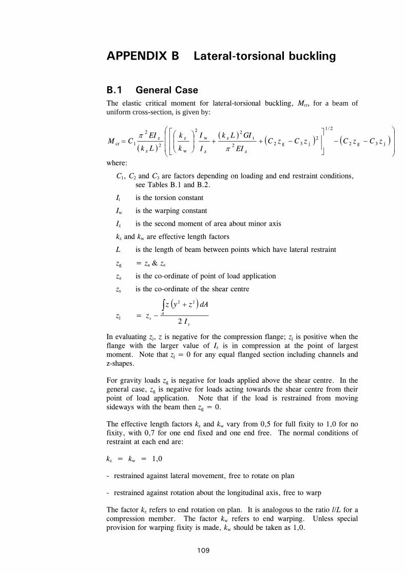
109
APPENDIX B Lateral-torsional buckling
B.1 General Case The elastic critical moment for lateral-torsional buckling, Mcr, for a beam of uniform cross-section, is given by:
j3g2
2/1
2j3g2
z2
t2
z
z
w
2
w
z
2z
z2
1cr zCzCzCzCEI
GILk
I
I
k
k
Lk
EICM
where:
C1, C2 and C3 are factors depending on loading and end restraint conditions, see Tables B.1 and B.2.
It is the torsion constant
Iw is the warping constant
Iz is the second moment of area about minor axis
kz and kw are effective length factors
L is the length of beam between points which have lateral restraint
zg = za zs
za is the co-ordinate of point of load application
zs is the co-ordinate of the shear centre
zj =
y
As I
dAzyz
z2
22
In evaluating zj, z is negative for the compression flange; zj is positive when the flange with the larger value of Iz is in compression at the point of largest moment. Note that zj = 0 for any equal flanged section including channels and z-shapes.
For gravity loads zg is negative for loads applied above the shear centre. In the general case, zg is negative for loads acting towards the shear centre from their point of load application. Note that if the load is restrained from moving sideways with the beam then zg = 0.
The effective length factors kz and kw vary from 0,5 for full fixity to 1,0 for no fixity, with 0,7 for one end fixed and one end free. The normal conditions of restraint at each end are:
kz = kw = 1,0
- restrained against lateral movement, free to rotate on plan
- restrained against rotation about the longitudinal axis, free to warp
The factor kz refers to end rotation on plan. It is analogous to the ratio l/L for a compression member. The factor kw refers to end warping. Unless special provision for warping fixity is made, kw should be taken as 1,0.

110
Table B.1 Values of factors C1 and C3 corresponding to values of effective length factor kz : End moment loading
Values of factors
C3
End moments and support conditions
Bending moment diagram
Value of kz
C1 0f 0f
1,0 1,00 1,000 = +1
0,5 1,05 1,019
1,0 1,14 1,000 = +¾
0,5 1,19 1,017
1,0 1,31 1,000 = +½
0,5 1,37 1,000
1,0 1,52 1,000 = +¼
0,5 1,60 1,000
1,0 1,77 1,000 = 0
0,5 1,86 1,000
1,0 2,06 1,000 0,850 = - ¼
0,5 2,15 1,000 0,650
1,0 2,35 1,000 f2,13,1 = - ½
0,5 2,42 0,950 f77,0
1,0 2,60 1,000 f55,0
= - ¾
0,5 2,57 0,850 f35,0
1,0 2,60 f f
MM
= - 1
0,5 2,45 f7,0125,0 f7,0125,0
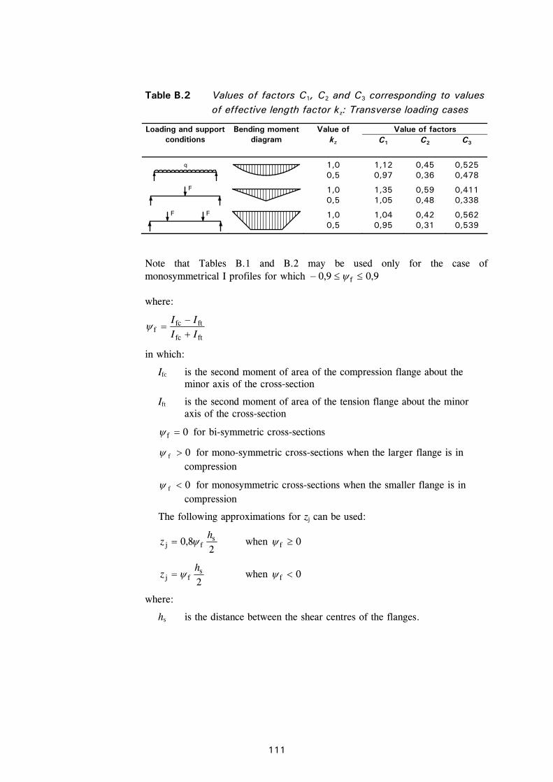
111
Table B.2 Values of factors C1, C2 and C3 corresponding to values of effective length factor kz: Transverse loading cases
Value of factors Loading and support conditions
Bending moment diagram
Value of kz C1 C2 C3
q
1,0 0,5
1,12 0,97
0,45 0,36
0,525 0,478
F
1,0 0,5
1,35 1,05
0,59 0,48
0,411 0,338
F F
1,0 0,5
1,04 0,95
0,42 0,31
0,562 0,539
Note that Tables B.1 and B.2 may be used only for the case of monosymmetrical I profiles for which 9,09,0 f
where:
ftfc
ftfcf II
II
in which:
Ifc is the second moment of area of the compression flange about the minor axis of the cross-section
Ift is the second moment of area of the tension flange about the minor axis of the cross-section
0f for bi-symmetric cross-sections
0f for mono-symmetric cross-sections when the larger flange is in compression
0f for monosymmetric cross-sections when the smaller flange is in compression
The following approximations for zj can be used:
28,0 s
fjh
z when 0f
2s
fjh
z when 0f
where:
hs is the distance between the shear centres of the flanges.
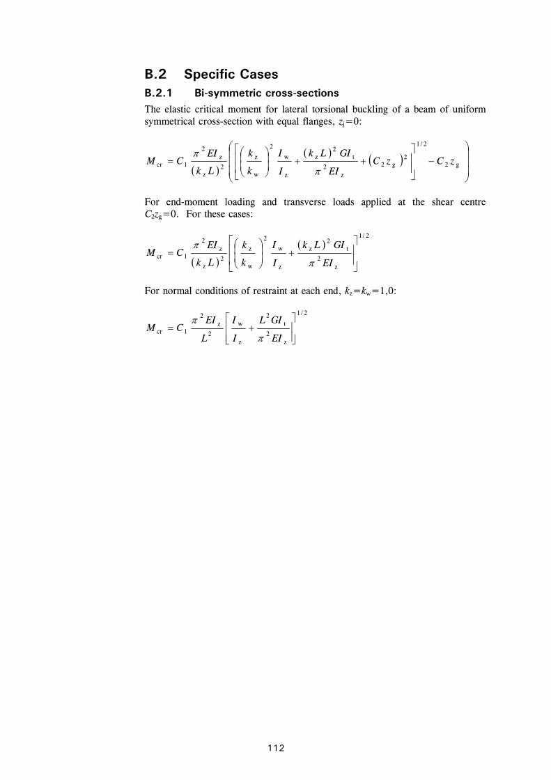
112
B.2 Specific Cases B.2.1 Bi-symmetric cross-sections The elastic critical moment for lateral torsional buckling of a beam of uniform symmetrical cross-section with equal flanges, zj=0:
g2
2/1
2g2
z2
t2
z
z
w
2
w
z
2z
z2
1cr zCzCEI
GILk
I
I
k
k
Lk
EICM
For end-moment loading and transverse loads applied at the shear centre C2zg=0. For these cases:
2/1
z2
t2
z
z
w
2
w
z
2z
z2
1cr
EI
GILk
I
I
k
k
Lk
EICM
For normal conditions of restraint at each end, kz=kw=1,0:
2/1
z2
t2
z
w
2
z2
1cr
EI
GIL
I
I
L
EICM
113
APPENDIX C Material data for deflection calculations
The secant modulus, ES, to be used in deflection calculations (see Section 5.4.6) should be ascertained for the member with respect to the rolling direction. If the orientation is not known, or cannot be ensured, then the value for the longitudinal directions should be used.
The value of the secant modulus may be obtained as follows:
ES = (ES1 + ES2)/2
where:
ES1 is the secant modulus corresponding to the stress in the tension flange
ES2 is the secant modulus corresponding to the stress in the compression flange.
Values of the secant moduli ES1 and ES2 for the appropriate orientation and serviceability design stress can be estimated from the following equation using the constants given in Table C.1. Alternatively, values for grades 1.4301, 1.4401 and 1.4462 may be taken from Table C.2 using linear interpolation as necessary.
f 00201
y
serEd, i,n
serEd, ,
,
i
is
E , +
EE and i = 1,2
where:
i,Ed,ser is the serviceability design stress in the tension or compression flange
E = 200 000 N/mm2.
As a simplification, the variation of ES along the length of the member may be neglected and the minimum value of ES for that member (corresponding to the maximum values of the stresses 1 and 2 in the member) may be used throughout its length.
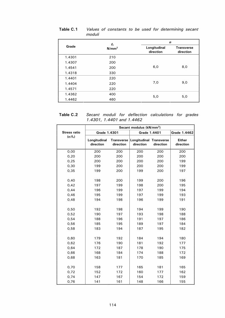
114
Table C.1 Values of constants to be used for determining secant moduli
n Grade
fy
N/mm2 Longitudinal direction
Transverse direction
1.4301 210
1.4307 200
1.4541 200
1.4318 330
6,0
8,0
1.4401 220
1.4404 220
1.4571 220
7,0
9,0
1.4362 400
1.4462 460 5,0 5,0
Table C.2 Secant moduli for deflection calculations for grades 1.4301, 1.4401 and 1.4462
Secant modulus (kN/mm2)
Grade 1.4301 Grade 1.4401 Grade 1.4462 Stress ratio (/fy)
Longitudinal direction
Transverse direction
Longitudinal direction
Transverse direction
Either direction
0,00 200 200 200 200 200 0,20 200 200 200 200 200 0,25 200 200 200 200 199 0,30 199 200 200 200 199 0,35 199 200 199 200 197
0,40 198 200 199 200 196 0,42 197 199 198 200 195 0,44 196 199 197 199 194 0,46 195 199 197 199 193 0,48 194 198 196 199 191
0,50 192 198 194 199 190 0,52 190 197 193 198 188 0,54 188 196 191 197 186 0,56 185 195 189 197 184 0,58 183 194 187 195 182
0,60 179 192 184 194 180 0,62 176 190 181 192 177 0,64 172 187 178 190 175 0,66 168 184 174 188 172 0,68 163 181 170 185 169
0,70 158 177 165 181 165 0,72 152 172 160 177 162 0,74 147 167 154 172 159 0,76 141 161 148 166 155
115
PART II – DESIGN EXAMPLES
This section gives thirteen design examples that illustrate the application of the design rules. The examples are:
Design example 1
A circular hollow section subject to axial compression.
Design example 2
A welded I-beam with a Class 4 cross-section subject to combined axial compression and bending.
Design example 3
Trapeziodal roof sheeting with a Class 4 cross-section subject to bending.
Design example 4
A welded hollow section joint subject to fatigue loading.
Design example 5
A welded joint.
Design example 6
A bolted joint.
Design example 7
A plate girder with a Class 4 cross-section subject to bending. Shear buckling is critical.
Design example 8
A plate girder with a Class 4 cross-section subject to bending. Resistance to transverse loads is critical.
Design example 9
A cold formed channel subject to bending with intermediate lateral restraints to the compression flange. Lateral torsional buckling between intermediate lateral restraints is critical.
Design example 10
A rectangular hollow section subject to combined axial compression and bending with 30 minutes fire resistance.
Design example 11
Trapeziodal roof sheeting with a Class 4 cross-section subject to bending – a comparison of designs with cold worked material and annealed material.
Design example 12
A lipped channel from cold worked material in an exposed floor subject to bending.
116
Design example 13
A stainless steel lattice girder from cold worked material subject to combined axial compression and bending with 30 minutes fire resistance.
The plate girders in examples 7 and 8 are from duplex grade 1.4462. The members in the other examples are from austenitic grades 1.4301 or 1.4401.
The references in the margin of the design examples are to text sections and expressions/equations in this publication, unless specifically noted otherwise.

117

117
Design example 1
A circular hollow section subject to axial compression.

119
Design example 2
A welded I-beam with a Class 4 cross-section subject to combined axial compression and bending.

123
Design example 3
Trapeziodal roof sheeting with a Class 4 cross-section subject to bending.

131
Design example 4
A welded hollow section joint subject to fatigue loading.

135
Design example 5
A welded joint.

143
Design example 6
A bolted joint.

149
Design example 7
A plate girder with a Class 4 cross-section subject to bending. Shear buckling is critical.

155
Design example 8
A plate girder with a Class 4 cross-section subject to bending. Resistance to transverse loads is critical.

161
Design example 9
A cold formed channel subject to bending with intermediate lateral restraints to the compression flange. Lateral torsional buckling between intermediate lateral restraints is critical.

169
Design example 10

177
Design example 11

183
Design example 12

191
Design example 13
192
List of sections, figures and tables
1 INTRODUCTION 1 1.1 Scope 1 1.2 Symbols 1 1.3 Conventions for member axes 3 1.4 Units 4 Figure 1.1 Dimensions and axes of sections 4
2 BASIS OF DESIGN 5 2.1 General requirements 5 2.2 Limit state design 5
Table 2.1 Recommended values of M 6
2.3 Loading 7 2.3.1 General 7 2.3.2 Ultimate limit state - Onshore factored loads 7 2.3.3 Ultimate limit state - Offshore factored loads 8 2.3.4 Serviceability limit state loads 9
3 MATERIALS: PROPERTIES, SELECTION AND DURABILITY 11 3.1 Material grades 11
3.1.1 Introduction 11 3.1.2 Relevant standards 12
Table 3.1 Specified mechanical properties of common stainless steels to EN 10088-2 13
Table 3.2 Chemical composition to EN 10088-2 14
Table 3.3 Minimum specified mechanical properties of austenitic grade fasteners to EN ISO 3506 15
Table 3.4 Chemical composition of fasteners to EN ISO 3506 16
3.2 Mechanical behaviour and design values of properties 16 3.2.1 Basic stress-strain behaviour 16
Figure 3.1 Typical stress-strain curves for stainless steel and carbon steel (for longitudinal tension) 17
3.2.2 Factors affecting stress-strain behaviour 17 Table 3.5 Cold worked strength levels in EN 10088-2 18
3.2.3 Typical values of properties 19 3.2.4 Design values of properties 19
3.3 Physical properties 21 Table 3.6 Room temperature physical properties, annealed condition 21
3.4 Effects of temperature 21 3.5 Selection of materials 22
3.5.1 Grades 23 Table 3.7 Suggested grades for atmospheric applications 24
3.5.2 Availability of product forms 24 3.6 Durability 25
3.6.1 Introduction 25 3.6.2 Types of corrosion and performance of steel
grades 26 3.6.3 Corrosion in selected environments 29
193
Table 3.8 Stainless steel grades for use in different soil conditions 31
Table 3.9 Design for corrosion control 32
Figure 3.2 Poor and good design features for durability 33
4 PROPERTIES OF SECTIONS 34 4.1 General 34 4.2 Maximum width-to-thickness ratios 34 4.3 Classification of cross-sections 34
4.3.1 General 34 Table 4.1 Maximum width-to-thickness ratios 35
4.3.2 Classification limits for parts of cross-sections 35
Table 4.2 Maximum width-to-thickness ratios for compression parts 36
4.4 Effective widths 38 4.4.1 Effective widths of elements in Class 4
cross-sections 38 Table 4.3 Internal compression elements 40
Table 4.4 Outstand compression elements 41
Figure 4.1 Class 4 cross-section subject to bending moment 42
Figure 4.2 Class 4 cross-section subject to compression 42
4.4.2 Effects of shear lag 42 4.4.3 Flange curling 42
4.5 Stiffened elements 43 4.5.1 Edge stiffeners 43 4.5.2 Intermediate stiffeners 43 4.5.3 Trapezoidal sheeting profiles with intermediate
flange stiffeners 43 Figure 4.3 Compression flange with one, two or multiple stiffeners 43
Figure 4.4 Intermediate stiffener 44
Figure 4.5 Notional widths of plane elements bp allowing for corner radii 45
4.6 Calculation of section properties 46 4.6.1 General 46 4.6.2 Influence of rounded corners 47
Figure 4.6 Real and idealised cross-section 48
4.6.3 Gross cross section 48 4.6.4 Net section 48
Figure 4.7 Staggered holes and critical fracture lines 1 and 2 49
Figure 4.8 Gauge length for angle with holes in both legs 49
4.7 Resistances of cross-sections 49 4.7.1 General 49 4.7.2 Cross-sections subject to tension 49 4.7.3 Cross-sections subject to compression 50 4.7.4 Cross-sections subject to bending moment
50 4.7.5 Cross-sections subject to shear 51
194
4.7.6 Cross-sections subject to combination of loads 51
4.7.7 Utilisation of strain hardening behaviour 52
5 MEMBER DESIGN 54 5.1 Introduction 54 5.2 Tension members 54 5.3 Compression members 54
5.3.1 General 54 5.3.2 Plate buckling 55 5.3.3 Flexural buckling 55
Figure 5.1 Buckling curves for flexural, torsional and torsional-flexural buckling 56
Table 5.1 Values of and 0 for flexural, torsional and torsional-flexural buckling 57
5.3.4 Torsional and torsional-flexural buckling 57 5.4 Flexural members 58
5.4.1 General 58 5.4.2 Lateral-torsional buckling 58
Figure 5.2 Buckling curves for lateral-torsional buckling 60
5.4.3 Shear resistance 60 Figure 5.3 Notation for geometrical dimensions 61
5.4.4 Web crushing, crippling and buckling 64 Figure 5.4 Buckling coefficients for different types of load application
65
Figure 5.5 Length of stiff bearing 65
5.4.5 Transverse stiffeners 66 Figure 5.6 Effective cross-section of stiffeners for buckling 67
5.4.6 Determination of deflections 67 5.5 Members subject to combinations of axial loads and
bending moments 68 5.5.1 Axial tension and bending 68 5.5.2 Axial compression and bending 69
6 JOINT DESIGN 71 6.1 General recommendations 71
6.1.1 Durability 71 Figure 6.1 Typical detail for connecting dissimilar materials (to avoid
bimetallic corrosion) 71
6.1.2 Design assumptions 72 6.1.3 Intersections and splices 72 6.1.4 Other general considerations 72
6.2 Bolted connections 73 6.2.1 General 73 6.2.2 Preloaded bolts 73 6.2.3 Connected parts 73
Figure 6.2 Symbols for defining position of holes 74
Table 6.1 Reduction factors 2 and 3 76
6.2.4 Fasteners 76
195
6.3 Welded connections 78 6.3.1 General 78
Table 6.2 Applicable steel grades and welding consumables 79
Table 6.3 Mechanical properties of all-weld metal according to EN 1600, EN 12072 and EN 12073 79
6.3.2 Fillet welds 79 Figure 6.3 Fillet weld throat thickness 80
Figure 6.4 Deep penetration fillet weld throat thickness 80
6.3.3 Butt welds 81 6.3.4 Welding cold worked stainless steel 81
7 FIRE RESISTANT DESIGN 82 7.1 General 82 7.2 Mechanical properties at elevated temperatures 82
Table 7.1 Retention factors for strength and stiffness and parameter g2, at elevated temperature 84
Table 7.2 Retention factors for strength and stiffness and parameter g2, at elevated temperature for cold worked material 85
7.3 Thermal properties at elevated temperatures 85 7.3.1 Thermal elongation 85 7.3.2 Specific heat 85 7.3.3 Thermal conductivity 86
7.4 Determination of structural fire resistance 86 7.4.1 Cross section classification 86 7.4.2 Tension members 86 7.4.3 Compression members 87
Figure 7.1 Buckling lengths lfi of columns in braced frames 88
7.4.4 Laterally restrained beams 88 Table 7.3 Adaptation factors 89
7.4.5 Laterally unrestrained beams 89 7.4.6 Members subject to axial compression and
bending 90 Table 7.4 Equivalent uniform moment factors, M 92
7.4.7 Calculation of temperature rise in stainless steel 92
8 FATIGUE 94
9 TESTING 95 9.1 General 95 9.2 Stress-strain curve determination 95 9.3 Tests on members 95
10 FABRICATION ASPECTS 97 10.1 Introduction 97 10.2 Storage and handling 98 10.3 Shaping operations 98
10.3.1 Cutting 98 10.3.2 Cold forming 99 10.3.3 Holes 99

196
10.4 Welding 100 10.4.1 Introduction 100 10.4.2 Processes 101
Table 10.1 Welding processes and their suitability 101
10.4.3 Consumables 101 10.4.4 Welding distortion 102 10.4.5 Metallurgical considerations 102 10.4.6 Post weld treatment 103 10.4.7 Inspection of welds 104
Table 10.2 Inspection methods for welds 104
10.5 Galling and seizure 104 10.6 Finishing 105
APPENDIX A Correlation between stainless steel designations 107
APPENDIX B Lateral-torsional buckling slenderness, lt 109 B.1 General Case 109
Table B.1 Values of factors C1 and C3 corresponding to values of effective length factor kz : End moment loading 110
B.2 Specific Cases 112
APPENDIX C Material data for deflection calculations 113

163
Typeset and page make-up by The Steel Construction Institute, Ascot, Berks. SL5 7QN Printed in Europe by the Alden Group, Oxford. 05-06 2000 (OSM503)