design - steelconstruction.info · in all the steel designs, except for the slim floor or slimdek...
TRANSCRIPT

SCI PUBLICATION 166
DESIGN OF STEEL FRAMED BUILDINGS FOR SERVICE INTEGRATION
P D McKenna BSc
R M Lawson BSc(Eng), PhD, CEng, MIStructE, MICE
Published by:
The Steel Construction Institute Silwood Park Ascot Berkshire SL5 7QN
Telephone: 01 344 623345 Fax: 01 344 622944
P166: Design of Steel Framed Buildings for Service Integration
Discuss me ...C
reat
ed o
n 22
Jul
y 20
09T
his
mat
eria
l is
copy
right
- a
ll rig
hts
rese
rved
. Use
of t
his
docu
men
t is
subj
ect t
o th
e te
rms
and
cond
ition
s of
the
Ste
elbi
z Li
cenc
e A
gree
men
t

INTERFACES
0 1997 The Steel Construction Institute
Apart from any fair dealing for the purposes of research or private study or criticism or review, as permitted under the Copyright Designs and Patents Act, 1988, this publication may not be reproduced, stored, or transmitted, in any form or by any means, without the prior permission in writing of the publishers, or in the case of reprographic reproduction only in accordance with the terms of the licences issued by the UK Copyright Licensing Agency, or in accordance with the terms of licences issued by the appropriate Reproduction Rights Organisation outside the UK.
Enquiries concerning reproduction outside the terms stated here should be sent to the publishers, The Steel Construction Institute, at the address given on the title page.
Although care has been taken to ensure, to the best of our knowledge, that all data and information contained herein are accurate to the extent that they relate to either matters of fact or accepted practice or matters of opinion at the time of publication, The Steel Construction Institute, the authors and the reviewers assume no responsibility for any errors in or misinterpretations of such data and/or information or any loss or damage arising from or related to their use.
Publications supplied to the Members of the Institute at a discount are not for resale by them.
Publication Number: SCI-P-166
ISBN 1 85942 047 8
British Library Cataloguing-in-Publication Data. A catalogue record for this book is available from the British Library.
.. I I
P166: Design of Steel Framed Buildings for Service Integration
Discuss me ...C
reat
ed o
n 22
Jul
y 20
09T
his
mat
eria
l is
copy
righ
t -
all r
ight
s re
serv
ed.
Use
of
this
doc
umen
t is
sub
ject
to
the
term
s an
d co
nditi
ons
of t
he S
teel
biz
Lice
nce
Agr
eem
ent

This publication concentrates on the design of long span composite beams with facility for service integration. It is prefaced by a review of modern building services and a brief statement as to the main factors influencing the design of the building structure and services throughout Europe. The European context is introduced in order to reflect the wide range of application of this information.
The publication was prepared by The Steel Construction Institute, UK. Its authors were Dr R M Lawson of SCI and M r P D McKenna, consultant to SCI, with major contributions from the following individuals and organisations:
Dr B Davidson YRM Anthony Hunt Associates (now at University of Sheffield)
Mr J Berry and M r P Sloman Ove Arup & Partners
Mr P Trebilcock SCI Consultant Architect M r R Smith and Mr J Blasby Davis Langdon & Everest
The illustrations of service layouts in Appendix B were prepared by YRM Engineers.
Support was received for the dissemination phase of this project from the European Commission (ECSC Agreements 721 O/SA/833 and PHlN 001 0). British Steel Sections, Plates & Commercial Steels have supported SCI in the research and development of composite construction systems, and more recently in the development of Slimdek.
The Department of the
and the Regions sponsored D E T R Environment, Transport TRANSPORT ENVIRONMENT
REQIONS the development phase of the project.
iii
P166: Design of Steel Framed Buildings for Service Integration
Discuss me ...C
reat
ed o
n 22
Jul
y 20
09T
his
mat
eria
l is
copy
right
- a
ll rig
hts
rese
rved
. Use
of t
his
docu
men
t is
subj
ect t
o th
e te
rms
and
cond
ition
s of
the
Ste
elbi
z Li
cenc
e A
gree
men
t

CONTENTS
SUMMARY Page No
... V l l l
1 MODERN OFFICE BUILDINGS 1
1 . l European Context 3
1.2 Climatic Factors 4
1.3 Steel Framed Buildings 5
1.4 Services Integration 7
1.5 Scope of the Publication 9
2 INTRODUCTION TO BUILDING SERVICES 1 1
2.1 The Need for Building Services 11
2.2 Types of Building Services 12
2.3 Air or Water Systems 12
3 FACTORS INFLUENCING SERVICES REQUIREMENTS 15
3.1 Building Location 16
3.2 Building Use 16
3.3 Building Form and Construction 16
4 TYPE OF AIR-CONDITIONING SYSTEMS 19
4.1 Ventilation and Cooling 19
4.2 Types of Air-conditioning System 21
4.3 All-Air Systems 23
4.4 Air and Water Systems 27
4.5 All-Water Systems 27
4.6 Packaged Refrigeration Unit Cooling Systems 30
4.7 Under-floor Distribution 31
V
P166: Design of Steel Framed Buildings for Service Integration
Discuss me ...C
reat
ed o
n 22
Jul
y 20
09T
his
mat
eria
l is
copy
right
- a
ll rig
hts
rese
rved
. Use
of t
his
docu
men
t is
subj
ect t
o th
e te
rms
and
cond
ition
s of
the
Ste
elbi
z Li
cenc
e A
gree
men
t

4.8 Laminar Flow System 34 INTERFACES
4.9 Chilled Ceilings 34
4.1 0 Comparison of Systems 37
5 INTERNAL DISTRIBUTIONS OF SERVICES 43
5.1 General Recommendations 44
5.2 Vertical Distribution of Services 44
5.3 Ceiling Grids 46
5.4 Horizontal Distribution of Services 47
6 STRUCTURAL OPTIONS FOR SERVICES INTEGRATION 49
6.1 Composite Construction 49
6.2 Slim Floors and Slimdek 50
6.3 Medium Span Systems 52
6.4 Long Span Construction 53
6.5 Composite Beams with Web Openings 55
6.6 Cellular and Castellated Beams 57
6.7 Haunched Beams 60
6.8 Tapered Beams 61
6.9 Composite Trusses 62
6.10 Stub Girders 64
6.1 1 Parallel Beam Systems 65
6.1 2 Summary of Service Zones Provided by the Various Structural Systems 67
6.1 3 Vertical Cores 67
vi
P166: Design of Steel Framed Buildings for Service Integration
Discuss me ...C
reat
ed o
n 22
Jul
y 20
09T
his
mat
eria
l is
copy
righ
t -
all r
ight
s re
serv
ed.
Use
of
this
doc
umen
t is
sub
ject
to
the
term
s an
d co
nditi
ons
of t
he S
teel
biz
Lice
nce
Agr
eem
ent

7
8
9
10
11
CASE STUDY: COMPARISON OF STRUCTURAL OPTIONS
7.1 Typical Steel Framed Building
7.2 Services Considerations
7.3 Structural Considerations
7.4 Structural Beam Details and Building Framing Plans
CASE STUDY: SERVICE DISTRIBUTION
CASE STUDY: COST IMPLICATIONS OF STRUCTURAL SYSTEM
9.1 General Aspects
9.2 Structure Cost
9.3 Cladding Costs
9.4 Services Distribution
9.5 Foundation Costs
9.6 Speed of Construction
9.7 Overall Cost Estimates
CONCLUSIONS
REFERENCES
APPENDIX A: Suggested Best Practice Criteria For Building Design
APPENDIX B: Service Distribution Drawings
69
69
72
74
77
83
85
85
86
88
88
90
91
92
95
97
103
107
vii
P166: Design of Steel Framed Buildings for Service Integration
Discuss me ...C
reat
ed o
n 22
Jul
y 20
09T
his
mat
eria
l is
copy
right
- a
ll rig
hts
rese
rved
. Use
of t
his
docu
men
t is
subj
ect t
o th
e te
rms
and
cond
ition
s of
the
Ste
elbi
z Li
cenc
e A
gree
men
t

INTERFACES SUMMARY
This publication summarises an investigation of the design of structural systems in modern commercial buildings which offer the facility for integration of the structure and building services within the same floor zone. Firstly, the publication reviews the general requirements for building services, particularly air-conditioning systems. Secondly, structural systems, utilising the principles of composite construction, are designed for spans of 15 m. Thirdly, the distribution of air-conditioning ducts throughout these buildings is established with respect to the structural systems considered in the investigation. Finally, general estimates of construction costs are made which take into account the influence of the costs of service distribution and other variable aspects of the construction.
The publication contains information on the structural design of the long span systems and includes examples of service drawings showing the distribution of the major services with respect to the structure and building frames considered. It concludes that the additional costs in choosing long span systems offering integration of structure and services may only be 0.1 to 2% of the total building cost in comparison to structures based on traditional span of 6 to 7.5 m.
Integration des services dans les ossatures en acier des immeubles
Resume Cette publication resume une etude concemart la conception de systemes structuraux dans des bdtiments commerciaux modernes qui offrent la possibilite d'une integration de la structure et des services du bstiment sur le mGme itage sol. En premier lieu, la publication examine les exigences generales des services du bdtiment, particulierement les systemes de conditionnement de /'air. En second lieu, les systemes structuraux employant les principes de construction mixte sont conGus pour des portees de 15 m. En troisieme lieu, la distribution des conduites de climatisation de I'air a travers ces bdtiments est etablie en tenant compte des systemes structuraux consideres dans I'etude. Enfin, des estimations generales des coiits de construction sont r6alis6es en tenant compte des
v111 ...
P166: Design of Steel Framed Buildings for Service Integration
Discuss me ...C
reat
ed o
n 22
Jul
y 20
09T
his
mat
eria
l is
copy
right
- a
ll rig
hts
rese
rved
. Use
of t
his
docu
men
t is
subj
ect t
o th
e te
rms
and
cond
ition
s of
the
Ste
elbi
z Li
cenc
e A
gree
men
t

coljts de la distribution des services et d'autres aspects variables de la construction.
f a publication comporte des informations sur la conception structurale des systPmes A longue port6e et comprend des exemples de plans des services indiquant la distribution des plus importants services concernant la structure et les bit is des constructions consid6r6ses. f 'etude conclut que les coljts supplementaires, lorsque I'on choisit les systemes de longue port6e offrant /'integration de la structure et des services, peuvent uniquement atteindre de 0. l A 2 % du coljt total du bitiment par rapport aux structures bas6es sur des portees traditionnelles de 6 A 7,5 m.
integration der Installationen in Stah I bauten
Zusammenfassung Das Buch faRt eine Untersuchung der Konstruktion von Bausystemen in modernen Gewerbebauten zusammen, die die Moglichkeit der lntegration von Konstruktion und Gebaudeversorgungssystemen innerhalb desselben Stockwerksbereichs bieten. Zunachst untersucht der Bericht die allgemeinen Anforderungen fur Gebaudeversorgungssysteme, insbesondere Klimaanlagen. Dann werden Konstruktionssysteme nach dem Verbundbauprinzip auf Spannweiten von 7 5 m ausgelegt. Danach wird die Fuhrung der Klimaanlagenleitungen durch die Gebaude hinsichtlich der untersuchten Bausysteme festgestellt. AbschlieBend fuhrt der Bericht allgemeine Baukostenschatzungen a u t die den €influR der Kosten fur die Verteilungssysteme und weitere variable Aspekte des Baus berucksichtigen.
Das Buch enthalt lnformationen zu den konstruktiven Gegebenheiten der Bausysteme fur groBe Spannweiten und enthalt Beispiele von Versorgungseinrichtungszeichnungen, die die Verteilung der Hauptversorgungssysteme hinsichtlich der aufgefuhrten Konstruktions- und Gebauderahmen darstellen. Die Untersuchung kommt zu dem SchluR, daR die zusatzlichen Kosten, die bei der Wahl von Systemen fur groBe Spannweiten, die die lntegration von Konstruktion und Versorgungssystemen bieten, entstehen, bei nur 0.1 bis 2 % der Gesamtbaukosten im Vergleich zu Standardkonstruktionen mit traditionellen Spannweiten von 6 bis 7,5 m liegen.
ix
P166: Design of Steel Framed Buildings for Service Integration
Discuss me ...C
reat
ed o
n 22
Jul
y 20
09T
his
mat
eria
l is
copy
righ
t -
all r
ight
s re
serv
ed.
Use
of
this
doc
umen
t is
sub
ject
to
the
term
s an
d co
nditi
ons
of t
he S
teel
biz
Lice
nce
Agr
eem
ent

INTERFACES Integracion de servicios en edificios aporticados de acero
Resumen Esta publicacidn resume un estudio sobre el proyecto de sistemas estructurales en edificios comerciales modernos que ofrecen la posibilidad de integracidn de la estructura y /as instalaciones del edificio dentro de la misma zona de 10s forjados.
En primer lugar se pasa revista a /os requisitos generales que deben cumplir /as instalaciones en /os edificios, en especial /os sistemas de aire acondicionado. A continuacidn se proyectan, para luces de 15 m, sistemas estructurales seglin 10s principios de /as estructuras mixtas. En tercer lugar se establece la distribucidn de conductos de aire acondicionado ajustindose a 10s sistemas estructurales considerados en el estudio. Finalmente se hacen estimaciones globales de /os costes de construccidn que tienen en cuenta la influencia de /os costes de la distribucidn de instalaciones y otros aspectos variables de la construccidn.
La publicacidn contiene datos sobre el proyecto de sistemas estructurales de vanos grandes e incluye como ejemplos dibujos de instalaciones mostrando la distribucidn de /as m is importantes en relacidn con /os pdrticos de la estructura del edificio considerado. E l resultado de la investigaci6n indica que /os costes adicionales resultantes al escoger sistemas de luces grandes con posibilidad de integracidn de la estructura y /os servicios puede ilegar a ser solo del 0. 1 a/ 2 % del coste total del edificio en comparacidn a proyectos tipicos con /os tradicionales vanos de 6 a 7.5 m.
X
P166: Design of Steel Framed Buildings for Service Integration
Discuss me ...C
reat
ed o
n 22
Jul
y 20
09T
his
mat
eria
l is
copy
right
- a
ll rig
hts
rese
rved
. Use
of t
his
docu
men
t is
subj
ect t
o th
e te
rms
and
cond
ition
s of
the
Ste
elbi
z Li
cenc
e A
gree
men
t

lntegrazione degli impianti in edifici a struttura intelaiata
Sommario Questa pubblicazione presenta in sintesi uno studio condotto sulla progettazione strutturale di moderni edifici ad us0 commerciale per i quali si vogliano integrare, all'interno del solaio di piano, i sistemi impiantistici dell 'edificio. Nella pubblicazione sono dapprima analizzatri i requisiti generali relativi ai servizi dell'edificio, con particolare riferimento ai sistemi per /'aria condizionata. In secondo luogo, e' affrontato i l tema della progettazione strutturale per interassi fino a 15 metri, sulla base delle regole di dimensionamento delle struttura composte. I / terzo punto affronta invece il problema della distribuzione dei condotti dell'aria condizionata all'interno dell'edificio, con riferimento a diverse tipologie strutturali. Infine viene presenta una valutazione globale dei costi di costruzione tenendo in conto l'incidenza economica degli impianti e dei loro sistemi distributivi oltre che di aspetti di altra natura legati alla fase costruttiva.
Questa pubblicazione riporta dettagli sulla progettazione strutturale di sistemi con travi di grande luce e presenta esempi di disegni impiantistici mostrando la distribuzione dei principali servizi per strutture e edifici a ossatura portante intelaiati. A conclusione di questo studio viene infine sottolineato ohe i costi aggiuntivi legati alla scelta di sistemi portanti con trave di grande luce per i quali sia possibile una concreta integrazione tra struttura e impianti possono essere sensibilmente limitati, variando tra 0.1 % e il 2% del costo totale dell'edificio, se paragonati con quelli associati invece a una progrettazione tradizionale riferita agli usuali interassi di 6 o 7.5 metri.
lntegrering av installationer i byggnader med stilstomme Sammanfattning Denna publikation sammanfattar en studie av utformningen av de stomsystem ti l l moderna kommersiella byggnader som mojliggor en integrering av installationerna i byggnadens bj8'lkagskonstruktion. forst ger publikationen en oversikt over generella krav p i byggnadens installationer, speciellt ventilationssystemet.
xi
P166: Design of Steel Framed Buildings for Service Integration
Discuss me ...C
reat
ed o
n 22
Jul
y 20
09T
his
mat
eria
l is
copy
right
- a
ll rig
hts
rese
rved
. Use
of t
his
docu
men
t is
subj
ect t
o th
e te
rms
and
cond
ition
s of
the
Ste
elbi
z Li
cenc
e A
gree
men
t

INTERFACES Darefter ges en oversikt over stomsystem, baserade p i samverkansteknik, och som ar dimensionerade for spannvidder p i upp t i l l 15 m. Kanaldragning av ventilationskanaler anpassade t i l l de stomsystem som redovisats i studien. Slutligen ges en uppskattning av bygglostnaden med hansyn ti l l inverkan av installationsdragningarna.
Publikationen innehiller information om dimensionering av stomsystem med stora spannvidder samt ol ika exempel p i hur installationernas dragning kan utfcjras si att man anpassar dessa t i l l den barande stommens fcjrutsdttningar. Studien fastslir att tilldggskostnaden f6.r att vdlja stomsystem med stora spdnnvidder och ell integreral installationssystem bara uppgir t i l l 0.1 t i l l 2% av den totala byggkostnaden i jdmfcjrelse med tradionella stommsystem med spdnnvidder p i 6 t i l l 7.5 m.
xi i
P166: Design of Steel Framed Buildings for Service Integration
Discuss me ...C
reat
ed o
n 22
Jul
y 20
09T
his
mat
eria
l is
copy
right
- a
ll rig
hts
rese
rved
. Use
of t
his
docu
men
t is
subj
ect t
o th
e te
rms
and
cond
ition
s of
the
Ste
elbi
z Li
cenc
e A
gree
men
t

1 MODERN OFFICE BUILDINGS
Office space is an increasingly international commodity, and the days of separate national cultures in workplace design and lifestyle may well be nearing an end. ‘Global’ companies seek office space in all key countries and compare national standards and products. Developers move from country to country, following demand. Investors buy property in any market that offers good growth prospects. Office staff are increasingly mobile and aware of opportunities afforded in other countries. Interchange is increasing.
The UK office market is dominated by commercial developers, for whom investment value is paramount, and a smaller owner-occupier market. North America is looked to as the most efficient r61e model for commercial development, and whilst
1
P166: Design of Steel Framed Buildings for Service Integration
Discuss me ...C
reat
ed o
n 22
Jul
y 20
09T
his
mat
eria
l is
copy
right
- a
ll rig
hts
rese
rved
. Use
of t
his
docu
men
t is
subj
ect t
o th
e te
rms
and
cond
ition
s of
the
Ste
elbi
z Li
cenc
e A
gree
men
t

INTERFACES British cultural and economic norms are still very different, convergence is occurring.
In Continental Europe, however, office development is currently dominated by ‘owner-occupation’. Companies build for themselves, or buy ’developer buildings’. Some cities have strong developer markets but the style is set by corporate buildings. This produces a radically different set of priorities in office design from the UWUS model. Buildings, especially corporate headquarters, tend to be more idiosyncratic, often free-standing, high quality and staff-oriented, compared to the standardised, relatively modest specification and investor-oriented space in the UK and US. In all countries, concern for health and comfort in offices is encouraging a move away from sealed, buildings towards more environmental friendly developments.
These commercial trends and attitudes exert a strong influence on all aspects of the building, such as choice of space planning modules, structural grid, services installations, as well as exterior and interior finishes. Despite the apparent ‘international’ consistency in building design, some countries have developed their own particular structural and environmental systems, reflecting the local climate, culture, national resources, as well as technological skills.
Steel framed buildings have become increasingly popular in Europe because they bring together the facility for speed of construction, column-free space, flexibility in planning, and adaptability to suit future needs. The market for steel frames in the commercial building sector is over 50% in the UK and Scandanvia, although it is less than 20% in France and Germany. This aspect suggests that the perceived advantages of steel in some countries have not extended throughout Europe.
The economic constraints on building construction have led to greater awareness of the cost of services and the potential for reducing costs without adversely affecting the use of the building. Recently, the British Council for Office$’) addressed the important issues in the design and specific form of modern commercial buildings, and a precis of their requirements is presented in Appendix A.
2
P166: Design of Steel Framed Buildings for Service Integration
Discuss me ...C
reat
ed o
n 22
Jul
y 20
09T
his
mat
eria
l is
copy
right
- a
ll rig
hts
rese
rved
. Use
of t
his
docu
men
t is
subj
ect t
o th
e te
rms
and
cond
ition
s of
the
Ste
elbi
z Li
cenc
e A
gree
men
t

1 . l European Context
The structure of the construction industry within each of the European countries dictates how buildings are procured. The client has a major influence on the building quality, but social attitudes and regulations also influence the building design. Therefore, the building stock within each country varies considerably. The following table defines, in general terms, the main factors influencing the commercial building market in the major countries of the European Union.
Table 1 Summary of the European market for building
Country Clients Social Concerns Resulting Quality
UK
Scandinavia
Germany and Netherlands
Property development companies with funds from banks, pension funds, and insurance companies.
Developers, Banks, insurance companies, contractor Syndicates.
Banks and insurance companies for owner- occupiers.
France and Property developers, Belgium owner-occupiers,
banks and insurance companies.
Regulations permit flexibility and innovation. Increased move to low energy solutions.
High level of awareness of thermal performance and hygiene, supported by strict National regulations.
High awareness of green issues and hygiene, supported by National Regulations.
Well regulated with bias to French products.
~~
Spain and Italy Funding by banks and Complex regulations insurance companies. and relatively poor Buildings often for building standards, sale, not rent. improving in line
with European Standards.
Construction standards suitable for rented occupation. Quality could be improved.
High quality solutions with innovative manufacturer-led solutions.
High cost, but low energy buildings of good quality.
Simple tried and tested solutions that are economic and functional.
Initial costs are low. Specifications have little consideration for cost in use.
The general factors that influence the choice of structure, major services, and building form are as follows:
National building regulations, and the building approval process.
3
P166: Design of Steel Framed Buildings for Service Integration
Discuss me ...C
reat
ed o
n 22
Jul
y 20
09T
his
mat
eria
l is
copy
right
- a
ll rig
hts
rese
rved
. Use
of t
his
docu
men
t is
subj
ect t
o th
e te
rms
and
cond
ition
s of
the
Ste
elbi
z Li
cenc
e A
gree
men
t

INTERFACES Form of construction contract, for example, the influence of ‘design and build’, or traditional ’client-consultant-contractor’ relationships.
Scope for innovation within the design and construction process. This may also be influenced by the fees to architect and other designers.
Activity within the building, including space requirements, occupancy patterns, and circulation areas.
Climatic factors (see below).
Economic arguments, as influenced by material and construction costs, and speed of construction.
Other factors such as architectural style, and local planning requirements, have an important effect on the form and appearance of the building.
1.2 Climatic Factors
Any discussion of building services in modern buildings in Europe should take into account the external environmental conditions, which can change dramatically from winter to summer. Five distinctive climatic regions may be identified in Europe, namely:
North west maritime countries; UK, Ireland, and Benelux and Northern France.
Western maritime regions; Western France and Northern Spain.
Northern European countries; Scandinavia.
Central European or continental countries; Germany, Eastern France, Austria, Switzerland.
Southern European countries; Spain, Portugal, Italy and Greece.
The general climatic zones are shown diagrammatically in Figure 1 . The temperatures shown relate to ‘design’ maximum and minimum temperatures which may be experienced over a number of days.
Table 2 presents the environmental factors, and the relevant features of the building design that differ among these regions. This information should be taken into account when assessing the application of the design guidance contained in this publication.
4
P166: Design of Steel Framed Buildings for Service Integration
Discuss me ...C
reat
ed o
n 22
Jul
y 20
09T
his
mat
eria
l is
copy
right
- a
ll rig
hts
rese
rved
. Use
of t
his
docu
men
t is
subj
ect t
o th
e te
rms
and
cond
ition
s of
the
Ste
elbi
z Li
cenc
e A
gree
men
t

Key Summer Winter
Figure 1 European climatic variations
1.3 Steel Framed Buildings
Steel frames are increasingly used in commercial buildings, and most steel frames are designed to achieve composite action with the concrete floor slab. The advantages of 'composite construction' are now well understood in terms of structural economy, good performance in service, and ease of construction. Design of composite structures i s covered by ENV 1994: Eurocode 4(*) and by national codes.
Coupled with this increase in the use of steel frames has been a demand for higher quality in the building fabric and services. It is recognised that the cost of the frame may only be 10 to 15% of the overall building cost, and therefore decisions on the choice of the structural form are more influenced by the usability and adaptability of the building to changing requirements.
5
P166: Design of Steel Framed Buildings for Service Integration
Discuss me ...C
reat
ed o
n 22
Jul
y 20
09T
his
mat
eria
l is
copy
right
- a
ll rig
hts
rese
rved
. Use
of t
his
docu
men
t is
subj
ect t
o th
e te
rms
and
cond
ition
s of
the
Ste
elbi
z Li
cenc
e A
gree
men
t

Table 2 Summary o f climatic conditions and building features INTERFACES
Country Climatic Features of building design
SummerNinter Air-conditioning Structure
UK +27"C/ - 4 °C Most high quality 3.5 to 4.5 m high humidity and buildings have floor-floor. High potentially high VAV/Fan Coil a/c. market share for winds. Mild Trend to passive steel. Long span winters. cooling. systems used in
prestige buildings.
Scandinavia +28"C/- 15°C Sealed, well 3.3 to 3.6 m cold winters insulated buildings floor-floor. High and short hot of high quality. Air market share for summers. change 8-1 0 steel using shallow
I/s/person. VAV floor construction. and over-floor systems commonly used.
~ ~~
Germany +31 "C/- 1 1 "C Often sealed 3.5 m floor-floor cold winters and buildings. VAV/Fan typical. Low hot summers, coil and chilled market share for typical of ceilings used. steel. Concrete is continental climate. Trend to passive dominant. Short
cooling. spans common.
France +33"C/- 5°C Infrequent use of 3 to 3.2 m floor- warm generally, a/c in all except floor. Low market high humidity in high quality share for steel. Pre- west. buildings. Fan coil cast concrete
systems are widely used. preferred.
Bene1 ux + 27"C/- 4°C Often air- 3.3 to 3.8 m floor- can be affected by conditioned. Trend floor. Low market continental climate. to passive cooling. share for steel.
._
Italy and Spain + 35"C/ + 1 "C Air-conditioning 3 to 3.2 m floor- long hot summers. often essential. Fan floor. Low market
coil systems share for steel, preferred. although increasing.
a/c =air-conditioning. VAV - Variable Air Volume. Vs - litres/second. These climatic observations apply to the typical conditions in each country.
6
P166: Design of Steel Framed Buildings for Service Integration
Discuss me ...C
reat
ed o
n 22
Jul
y 20
09T
his
mat
eria
l is
copy
right
- a
ll rig
hts
rese
rved
. Use
of t
his
docu
men
t is
subj
ect t
o th
e te
rms
and
cond
ition
s of
the
Ste
elbi
z Li
cenc
e A
gree
men
t
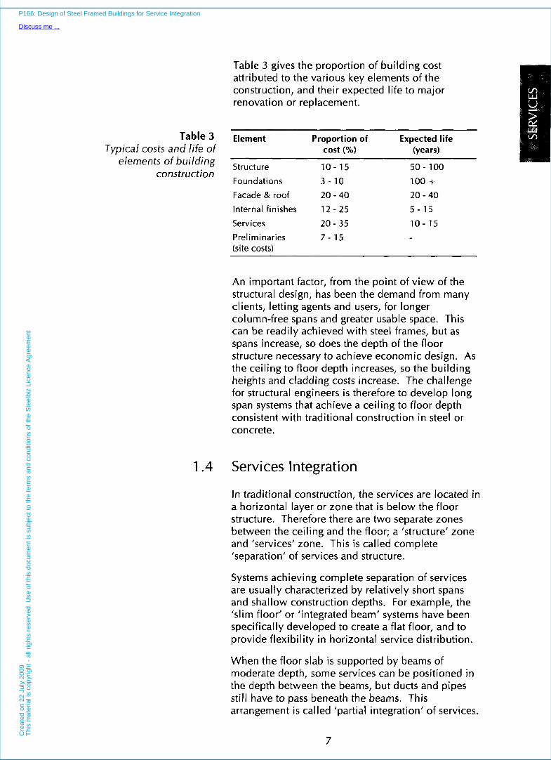
Table 3 gives the proportion of building cost attributed to the various key elements of the construction, and their expected life to major renovation or replacement.
Table 3 Element Proportion of Expected life Typical costs and life of cost (0%) (years)
elements of building Structure 1 0 - 15 50 - 100 construction
Foundations 3 - 1 0 100 + Facade & roof 20 - 40
Internal finishes 12 - 25
Services 20 - 35 Preliminaries 7 - 15 (site costs)
20 - 40 5 - 15
10 - 15
An important factor, from the point of view of the structural design, has been the demand from many clients, letting agents and users, for longer column-free spans and greater usable space. This can be readily achieved with steel frames, but as spans increase, so does the depth of the floor structure necessary to achieve economic design. As the ceiling to floor depth increases, so the building heights and cladding costs increase. The challenge for structural engineers is therefore to develop long span systems that achieve a ceiling to floor depth consistent with traditional construction in steel or concrete.
1.4 Services Integration
In traditional construction, the services are located in a horizontal layer or zone that is below the floor structure. Therefore there are two separate zones between the ceiling and the floor; a ‘structure’ zone and ‘services’ zone. This is called complete ‘separation’ of services and structure.
Systems achieving complete separation of services are usually characterized by relatively short spans and shallow construction depths. For example, the ‘slim floor’ or ‘integrated beam’ systems have been specifically developed to create a flat floor, and to provide flexibility in horizontal service distribution.
When the floor slab is supported by beams of moderate depth, some services can be positioned in the depth between the beams, but ducts and pipes still have to pass beneath the beams. This arrangement i s called ‘partial integration’ of services.
7
P166: Design of Steel Framed Buildings for Service Integration
Discuss me ...C
reat
ed o
n 22
Jul
y 20
09T
his
mat
eria
l is
copy
right
- a
ll rig
hts
rese
rved
. Use
of t
his
docu
men
t is
subj
ect t
o th
e te
rms
and
cond
ition
s of
the
Ste
elbi
z Li
cenc
e A
gree
men
t

INTERFACES If the beams are deep enough, it i s possible to pass the services through the beams at pre-determined locations so that the structure and services occupy the same horizontal zone. This is called 'full integration' of services. These forms of structure- service integration are illustrated in Figure 2.
I -L T I Raised floor - Floor slab
Secondary beam Primary beam Structure zone l - - - - - - - - - _ - _ ~
-
1 Service zone
1. Separation of structure and service zones (Medium span composite beams)
\ L - , , - _$.
\ Opening in web of primary beam 2. Partial integration of structure and service zones
(Long span composite beams)
T J I I . , . , : , , I . , ; , ;:
beam/ 0 \ \
\ ' Primary beam - 1 L -
T
1 service zone Structure and
3. Complete integration of structure and service zones (Parallel beam system)
Figure 2 Various forms o f structure-services integration
Long span beams with facility for service integration can be designed to achieve a ceiling - floor depth close to that of traditional construction. Often, careful layout of the structural elements can lead to flexibility in service distribution, as illustrated in Figure 3 where a 'corridor' zone for major ducts provides 'partial' integration of services in a conventional composite beam and slab arrangement.
8
P166: Design of Steel Framed Buildings for Service Integration
Discuss me ...C
reat
ed o
n 22
Jul
y 20
09T
his
mat
eria
l is
copy
right
- a
ll rig
hts
rese
rved
. Use
of t
his
docu
men
t is
subj
ect t
o th
e te
rms
and
cond
ition
s of
the
Ste
elbi
z Li
cenc
e A
gree
men
t

Much information on structural systems that achieve effective integration of services is available from North America(3) and the UK(4), where long span composite buildings have been in vogue for 10 to 15 years. There are now many examples of where these systems have been used in practice: guidance on their design features is covered in Section 6 and in other publications in the reference list.
Figure 3 Example of partial services integration
1.5 Scope of the Publication
The publication addresses the potential use of longer span beams offering facility for integration of services, and reviews the building services that may be used in modern commercial buildings throughout Europe. The benefits of different structural systems are assessed for one building form which is typical of a modern commercial building. The conclusions from this assessment may be readily extended to other building forms and spans.
The structural systems are based on a 15 m span between facades. This span was considered to be the most representative for the range of long span structural systems currently in use. Comparisons are made with shorter span systems which use a central line of columns.
9
P166: Design of Steel Framed Buildings for Service Integration
Discuss me ...C
reat
ed o
n 22
Jul
y 20
09T
his
mat
eria
l is
copy
right
- a
ll rig
hts
rese
rved
. Use
of t
his
docu
men
t is
subj
ect t
o th
e te
rms
and
cond
ition
s of
the
Ste
elbi
z Li
cenc
e A
gree
men
t
INTERFACES This publication will assist clients and designers in making decisions at the concept or scheme stage of a building project. It addresses the spatial and performance requirements of modern building services in air conditioned offices, and compares these spatial requirements to the service zones provided by the structural systems that have been developed for long span applications.
10
P166: Design of Steel Framed Buildings for Service Integration
Discuss me ...C
reat
ed o
n 22
Jul
y 20
09T
his
mat
eria
l is
copy
right
- a
ll rig
hts
rese
rved
. Use
of t
his
docu
men
t is
subj
ect t
o th
e te
rms
and
cond
ition
s of
the
Ste
elbi
z Li
cenc
e A
gree
men
t

2 INTRODUCTION TO BUILDING SERVICES
2.1 The Need for Building Services
Building services provide and maintain an artificial internal climate within the building when subject to a range of external climates. The building envelope is the barrier between the two climates. When carefully designed to interact with the service systems, the building envelope is not only the weatherproof barrier, but can also assist in creating the appropriate internal environment economically.
Building services have evolved and become more complex as the expectations of the quality of the environment within buildings has increased.
P166: Design of Steel Framed Buildings for Service Integration
Discuss me ...C
reat
ed o
n 22
Jul
y 20
09T
his
mat
eria
l is
copy
right
- a
ll rig
hts
rese
rved
. Use
of t
his
docu
men
t is
subj
ect t
o th
e te
rms
and
cond
ition
s of
the
Ste
elbi
z Li
cenc
e A
gree
men
t

INTERFACES The use of the building dictates the internal requirements, the degree of control to be exercised over the conditions, and the operational duration over which they must be maintained (8, 10 or 24 hours a day). The operation of the building will dictate specific requirements for such factors as:
temperature control
room acoustics
roodtask lighting levels and quality
air quality and space cleanliness
humidity control
smoke or other gas exhaust
odour control.
2.2 Types of Building Services
Building services are generally divided into three categories:
Mechanical Services
Electrical Services
Fire Safety Services
Mechanical services include the heating, ventilating and cooling systems. They generally occupy the largest volume, and emphasis is given here to fully explain the various mechanical systems that are most commonly installed in modern commercial buildings. Low capital cost, low running cost or accurate temperature and humidity control influence the type of system that is selected. The advantages and disadvantages of the more commonly used systems are discussed. General guidance on building services is given in References (5) and (6).
2.3 Air or Water Systems
The different types of heating, ventilating and cooling system wil l be discussed in Section 4.
Air or water is used in buildings as the medium by which energy is distributed. However, to transport energy by air takes up much more space than by water. This is because:
12
P166: Design of Steel Framed Buildings for Service Integration
Discuss me ...C
reat
ed o
n 22
Jul
y 20
09T
his
mat
eria
l is
copy
right
- a
ll rig
hts
rese
rved
. Use
of t
his
docu
men
t is
subj
ect t
o th
e te
rms
and
cond
ition
s of
the
Ste
elbi
z Li
cenc
e A
gree
men
t

Specific heat capacity of air = 1.02 kJ/kg"C
Specific heat capacity of water = 4.1 8 kJ/kg"C
These figures mean that water can carry approximately four times more energy per kg than air, and 4000 times more in terms of unit volume.
Although air systems take up more space than water systems, they are invariably used in modern office buildings, particularly those with 'sealed' windows. This is because most buildings require fresh air to be circulated to occupants in sufficient volume to achieve air quality, and therefore heating and cooling are most easily provided by enhancements to the air circulation system.
13
P166: Design of Steel Framed Buildings for Service Integration
Discuss me ...C
reat
ed o
n 22
Jul
y 20
09T
his
mat
eria
l is
copy
right
- a
ll rig
hts
rese
rved
. Use
of t
his
docu
men
t is
subj
ect t
o th
e te
rms
and
cond
ition
s of
the
Ste
elbi
z Li
cenc
e A
gree
men
t

INTERFACES
14
P166: Design of Steel Framed Buildings for Service Integration
Discuss me ...C
reat
ed o
n 22
Jul
y 20
09T
his
mat
eria
l is
copy
right
- a
ll rig
hts
rese
rved
. Use
of t
his
docu
men
t is
subj
ect t
o th
e te
rms
and
cond
ition
s of
the
Ste
elbi
z Li
cenc
e A
gree
men
t

3 FACTORS INFLUENCING SERVICES REQUIREMENTS
The air-conditioning or mechanical ventilation system selected to serve the needs of the building occupies considerable space, and is a considerable proportion of the total building cost. Hence, these requirements should be considered at the initial stages of the conceptual design of a building, including whether or not an air-conditioning system is needed.
The factors influencing the sizing and selection of the air-conditioning system are given'below.
15
P166: Design of Steel Framed Buildings for Service Integration
Discuss me ...C
reat
ed o
n 22
Jul
y 20
09T
his
mat
eria
l is
copy
right
- a
ll rig
hts
rese
rved
. Use
of t
his
docu
men
t is
subj
ect t
o th
e te
rms
and
cond
ition
s of
the
Ste
elbi
z Li
cenc
e A
gree
men
t

INTERFACES 3.1 Building Location
(a) Climate - Variations in solar radiation, air temperature and humidity all affect the energy requirements of a building [refer to Table 21.
(b) Exposure - The height of the building and the direction and strength of prevailing winds wil l also affect the energy usage in a building.
(c) Pollution - This is usually only a consideration in an urban environment, and can be in the form of noise and traffic fumes. The building may need to be ‘sealed’ thus requiring use of mechanical ventilation systems.
(d) Shape of Site - The shape of the site may dictate the size and shape of the building, which affects both system selection and energy usage.
(e) Surrounding Buildings - Other buildings may create problems by reducing daylight penetration and solar gains, and possibly unacceptable wind patterns around the building which affect the ventilation conditions.
(f) Planning Considerations - National and local regulations, and the restrictions imposed for fire protection purposes may combine to influence the building services used.
3.2 Building Use
The use of the building, or even parts of the building, dictates the desired internal temperatures, the required degree of control and the operational duration over which the temperatures must be maintained (see Section 2.1).
Capital and running costs should also be taken into consideration in the selection of the building services.
3.3 Building Form and Construction
(a) Shape - Ideally, the ratio of the envelope surface area to usable floor area should be minimized. Interpreting this general principle literally leads to the conclusion that large buildings, having a smaller ratio of surface area to floor area, are more economical in heating/cooling requirements than are small buildings.
16
P166: Design of Steel Framed Buildings for Service Integration
Discuss me ...C
reat
ed o
n 22
Jul
y 20
09T
his
mat
eria
l is
copy
right
- a
ll rig
hts
rese
rved
. Use
of t
his
docu
men
t is
subj
ect t
o th
e te
rms
and
cond
ition
s of
the
Ste
elbi
z Li
cenc
e A
gree
men
t

However, relatively narrow buildings may in fact use less energy than deep plan structures because they may not need air-conditioning and so much artificial lighting. Benefits from windows that provide natural light and ventilation can extend up to 6 m inwards from the windows.
(b) Mass - All major elements of a building; floors, external walls and roof contribute to determine the building mass.
The effect the building ’thermal capacity’ has on the selection of the air-conditioning system may be important in terms of acceptable internal conditions and running costs. In buildings of high thermal inertia, external climatic changes are slow to affect the internal environment, as these buildings heat up and cool down slowly.
In a lightweight building, with large amounts of glass and/or lightweight highly insulated cladding panels in the external envelope, speed of response is therefore important in the design of the services system if a constant internal temperature is to be maintained. Studies have shown that the concrete floors in a composite structure are able to regulate daily internal temperatures even in a lightweight structure. This is a subject of a recent SCI publicatiorf”.
(c) Orientation - Beneficial heating through south facing windows can occur. In air-conditioned buildings, the major axis of the building should ideally be in the EasWest direction for optimum performance, as it gives a lower cooling load, which becomes more significant as the amount of glass in the building envelope increases (see Figure 4).
(d) Insulation Levels - The walls and roof of a building should have an appropriate level of thermal insulation to reduce heat loss. The heat loss through the roof can be a major factor for low rise buildings of large plan.
(e) Glazing - The amount of glazing provided in the external envelope is the most influential factor on the sizing of the heating and cooling systems. A simple rule often used i s that 20-30% glazing of the outside facade provides the benefit of natural lighting and ventilation to a depth of about 6 m from the windows. If a greater amount of glazing is used, more solar protection
17
P166: Design of Steel Framed Buildings for Service Integration
Discuss me ...C
reat
ed o
n 22
Jul
y 20
09T
his
mat
eria
l is
copy
right
- a
ll rig
hts
rese
rved
. Use
of t
his
docu
men
t is
subj
ect t
o th
e te
rms
and
cond
ition
s of
the
Ste
elbi
z Li
cenc
e A
gree
men
t

INTERFACES A Increasing building cooling load
Glass area 75% of external wall
i \ I I
I Glass area 25% of external wall
I l I I I I Major building
axis alignment
N-S Alignment W-E Alignment N-S Alignment
The cooling load is increased with greater area of glass
Figure 4 Cooling load variation with building orientation
may be necessary to prevent excessive heat gains and to reduce coo1in.g loads.
The choice between openable or sealed windows is dependent upon a number of factors; building use, external noise levels, external pollution levels, site wind speeds, building height and the building's thermal inertia. To many occupants, the opportunity to open a window also gives great psychological benefit.
(f) Lighting - The level of lighting provided in the space is totally dependent upon the task being performed. Recommended task lighting levels are given in National Codes and are dependent on building shape, location and the percentage of glazing in the external facade. Deep plan buildings have a greater requirement for artificial lighting and for ventilation systems to remove the heat generated by the lights.
18
P166: Design of Steel Framed Buildings for Service Integration
Discuss me ...C
reat
ed o
n 22
Jul
y 20
09T
his
mat
eria
l is
copy
right
- a
ll rig
hts
rese
rved
. Use
of t
his
docu
men
t is
subj
ect t
o th
e te
rms
and
cond
ition
s of
the
Ste
elbi
z Li
cenc
e A
gree
men
t

4 TYPES OF AIR- CONDITIONING SYSTEMS
The term ‘air-conditioning’ defines the control of internal space temperature, via heating and cooling, and humidity to pre-determined levels. These settings are maintained within limits all year round. Air-conditioning systems which control only the air temperature are more correctly termed ’comfort cooling’ systems.
4.1 Ventilation and Cooling
Ventilation In a situation where natural ventilation through opening windows in the external walls is not possible, or where the internal environment
19
P166: Design of Steel Framed Buildings for Service Integration
Discuss me ...C
reat
ed o
n 22
Jul
y 20
09T
his
mat
eria
l is
copy
right
- a
ll rig
hts
rese
rved
. Use
of t
his
docu
men
t is
subj
ect t
o th
e te
rms
and
cond
ition
s of
the
Ste
elbi
z Li
cenc
e A
gree
men
t

INTERFACES necessitates a particular degree of control, fresh air wi l l have to be continually provided to the space via mechanical ventilation. Fresh air supply is normally expressed in terms of the ‘air change rate’, or air changes per hour. Typical recommended air change rates range from 6 per hour in offices, to 10 - 15 in restaurants and other special applications.
Alternatively, the air supply may be expressed in terms of the air required by each occupant. For high quality applications, an air supply rate of 8-10 litres/sec/person is required to maintain a fresh atmosphere.
The various components of an air-conditioning or comfort cooling system are shown diagrammatically in Figure 5.
In all cases, cooling is provided by refrigeration, and the low grade heat extracted from the building is ejected to the atmosphere. The refrigeration system is required to do more work in summer, both to cool the internal space, and also to ensure that the ejected air is at a higher temperature than the ambient air.
When included the system may then be said to be an air conditioning system
Frost l Intake protecting Filter Cooling Humidifier Heating Supply louvre heating coil coil * coil fan
I-- - /-‘ .l I I ; \ 10 0 I \ I-- -~-‘LT- Z‘I- - _ _ _ _ J
I ) ,
----- F-------
> I O Q ; ’ L- Combination of these units make air handling units
Exhaust air
TJ- R+ l
/ I CondGoned 1
Occupied space supply air
Exhaust Exhaust louvre fan
Figure 5 Components of an air-conditioning or comfort cooling system
Mechanical ventilation, with heating The air change rate has to be enhanced mechanically in areas which cannot be naturally ventilated by opening windows in the external wall.
20
P166: Design of Steel Framed Buildings for Service Integration
Discuss me ...C
reat
ed o
n 22
Jul
y 20
09T
his
mat
eria
l is
copy
right
- a
ll rig
hts
rese
rved
. Use
of t
his
docu
men
t is
subj
ect t
o th
e te
rms
and
cond
ition
s of
the
Ste
elbi
z Li
cenc
e A
gree
men
t

When both the cooling coil and humidifier are removed from the air-conditioning system in Figure 5, the remaining system is known simply as a ‘mechanical ventilation’ system.
The air is heated in winter, but in summer, air is supplied at the prevailing external temperature, which is often in excess of the desired internal space temperature. The internal temperatures in the summer are therefore dependent upon the outside temperature, which may be unacceptable to the occupants, or to the processes inside the building.
Comfort criteria The cooling effect on the occupants within a building is influenced by three factors: the ambient air temperature, the surface temperature (radiation), and air movement (convection). These three effects influence the design of the ventilation and cooling system.
Detailed research of occupant comfort in buildings has led to the establishment of an empirical comfort factor called the ‘resultant temperature’, which is defined as follows:
Resultant temperature = ’/2 x Air temperature
+ ?h x Room surface temperature.
Air speed is usually low in modern commercial buildings and its effect on the resultant temperature can be neglected. The total cooling effect is therefore a combination of supplying cool air, and/or cooling of the surfaces of the space thereby affecting radiant cooling. Consideration of this aspect has led to the development of chilled ceilings (see Section 4.9).
4.2 Types of Air-conditioning System
There are three main components to an air- conditioning system; the central heating/cooIing machinery, the distribution/control system and the terminal outlet devices. The central machinery varies little in function and size, or in plant room location from country to country. Fuel sources and machine design may vary but this has little overall effect on the building form and structural solution for a typical commercial development.
21
P166: Design of Steel Framed Buildings for Service Integration
Discuss me ...C
reat
ed o
n 22
Jul
y 20
09T
his
mat
eria
l is
copy
right
- a
ll rig
hts
rese
rved
. Use
of t
his
docu
men
t is
subj
ect t
o th
e te
rms
and
cond
ition
s of
the
Ste
elbi
z Li
cenc
e A
gree
men
t

INTERFACES However, the distribution system comprising terminal heating, cooling, ventilating and air- conditioning equipment can vary significantly in shape, size and function. It is this part of the system that is located within or adjacent to the occupied zone of the building, and as such can influence the shape or depth of the structure and that of the services zone.
The terminal equipment provides the link between the central items of machinery and the occupants of the building. Its function is to create the desired thermal environment by utilising the heating, cooling and air handling capabilities of the main plant.
The generic types of air-conditioning or ‘comfort cooling’ systems are:
Al l air systems: Constant Volume, or Variable Air Volume (VAV)
Air-water systems: Induction units, Fan Coil Units (FCU) and chilled ceilings with a primary air supply.
All water systems: Unitary Fan Coil Units and reversible heat pumps, Fan Coil Units without primary air supply.
Refrigerant Split and packaged refrigerant systems: systems, with or without
primary systems air supply.
The most commonly used ‘comfort cooling systems’ for office building applications are the Variable Air Volume system (VAV) and the Fan Coil system.
Often, VAV systems are used in buildings with single owner occupiers, because of their lower running costs. Fan Coil systems are more often used in speculative buildings because of the lower capital costs and greater degree of local control to the space being serviced.
There are also significant differences in the use of these systems throughout Europe, because of the climatic conditions that prevail (see Table 2).
22
P166: Design of Steel Framed Buildings for Service Integration
Discuss me ...C
reat
ed o
n 22
Jul
y 20
09T
his
mat
eria
l is
copy
right
- a
ll rig
hts
rese
rved
. Use
of t
his
docu
men
t is
subj
ect t
o th
e te
rms
and
cond
ition
s of
the
Ste
elbi
z Li
cenc
e A
gree
men
t

4.3 All-Air Systems
4.3.1 General features of all-air systems An All-Air system provides temperature and humidity control of the air supplied by the system. No additional cooling is required in the occupied space. The system supplies and extracts a constant volume of air and provides ventilation of the building spaces served. The air may be 100°/o fresh or, in order to save energy, may consist of a mixture of fresh and re-circulated air. Heating of the space may be provided by the same airstream or enhanced by local heating panels at the building perimeter.
Air is heated or cooled centrally, and where it is reheated in sub-distribution ducts it is termed a Constant Volume-Multi-zone system. These systems offer improved local control over single zone systems, but may increase energy use.
The cooling coil in All-Air systems makes use of chilled water provided by the refrigeration plant, and ’comfort cooling’ is provided. With the addition of a humidifier, ‘air-conditioning’ is also provided (see Figure 5).
‘Comfort cooling’ normally suffices in temperate climates because people can tolerate typically 20-60% relative humidity without severe discomfort. The acceptable degree of humidity may also depend on sensitive equipment or other uses within the controlled space, and this may be a more important consideration than the needs of the occupants.
The circulation of air around the building for heating and cooling also has other benefits. It provides the mechanism by which fresh air for ventilation and control of odours can be introduced into every space served by the system. Also, in case of fire, the ductwork system can be used to provide smoke clearance, most importantly in multi-storey buildings which have phased evacuation from the building. In an emergency, an All-Air ductwork system having an automatic fire emergency mode of operation can be used to maintain smoke-free escape routes.
The design of the ductwork system for the distribution of air throughout the building is based on either low or high velocity air movement. Low velocities are suitable for simple systems, but would result in loss of useable space because of the use of large ducts in complex or large buildings. Most large cooling and ventilation systems therefore utilise high velocity air movement.
23
P166: Design of Steel Framed Buildings for Service Integration
Discuss me ...C
reat
ed o
n 22
Jul
y 20
09T
his
mat
eria
l is
copy
right
- a
ll rig
hts
rese
rved
. Use
of t
his
docu
men
t is
subj
ect t
o th
e te
rms
and
cond
ition
s of
the
Ste
elbi
z Li
cenc
e A
gree
men
t

INTERFACES Although high velocity systems reduce duct sizes and save space, they usually have high system resistances, increasing the fan motor size and the running costs. High velocity air movements are also noisy and therefore, in most buildings, the velocity of the air introduced into the occupied space has to be reduced and the noise generated has to be attenuated (dampened).
All-Air systems of all types have the following features and advantages:
The central location of major equipment means that operational maintenance is confined to plant room areas.
Heat recovery systems may be readily incorporated.
Free cooling using outside air alone can be maximised. This reduces the use of the mechanical refrigeration equipment, hence saving on running costs.
They allow good design flexibility for optimum air distribution, draught control and local requirements.
They are well suited to applications requiring unusual exhaust air rates.
Drain pipes and filters are not needed in occupied space.
Air can be delivered through floor, ceiling and displacement diffusers.
The disadvantages of All-Air systems are:
Large ducts for air distribution take up space. This can potentially increase the floor to ceiling depth, and thus increase the building height.
In locations with low outside temperatures, and where the air system (not radiation) is used to heat perimeter areas, fans must operate longer during unoccupied periods to maintain the desired temperatures.
Air balancing of the completed system can be difficult especially in cases without built-in self balancing devices.
Access to air terminals demands particular attention to ensure that the system can be fully maintained after completion of other room finishes and features.
24
P166: Design of Steel Framed Buildings for Service Integration
Discuss me ...C
reat
ed o
n 22
Jul
y 20
09T
his
mat
eria
l is
copy
right
- a
ll rig
hts
rese
rved
. Use
of t
his
docu
men
t is
subj
ect t
o th
e te
rms
and
cond
ition
s of
the
Ste
elbi
z Li
cenc
e A
gree
men
t
4.3.2 VAV systems One type of All-Air system keeps the supply air temperatures constant and varies the volume of air supplied. This is known as a Variable Air Volume (VAV) system.
All-Air VAV systems can be further divided into two classes; single duct systems and dual duct systems. A single duct system has a common duct for distribution of air, usually at a preset temperature, and this feeds all terminal devices. A dual duct system has separate hot and cold air distribution ductwork and each terminal unit blends the air to achieve the required supply temperature.
All-Air VAV systems are generally used in buildings that require individual control and have multiple zones, such as cellular offices. These systems are also used in special applications for close control of temperature and humidity, including ‘clean rooms’ and computer rooms.
The Variable Air Volume (VAV) system has the same advantages as those for other All-Air systems, but has the following additional advantages:
Higher air velocities can be used in the main distribution ductwork, consequently reducing duct sizes and saving space and costs.
The high velocity distribution of air to terminal devices which house their own volume regulators make the system virtually self balancing, reducing on site commissioning time.
The size of a typical VAV terminal box is 900 mm long by 400 mm square or diameter (Figure 6). The VAV boxes can be located between beams so that they occupy less apparent space.
Full advantage can be taken of the changing heat loads in the building. The air quantities may be reduced from the designed peak load to match the actual load and can operate between 65% and 100% of the maximum load.
Varying the total air volume that is delivered, according to the required use, reduces running costs.
Local control of the supplied air is available to suit individual needs.
VAV systems are relatively quiet, particularly when operating at reduced volumes.
Separate perimeter heating can be provided.
25
P166: Design of Steel Framed Buildings for Service Integration
Discuss me ...C
reat
ed o
n 22
Jul
y 20
09T
his
mat
eria
l is
copy
right
- a
ll rig
hts
rese
rved
. Use
of t
his
docu
men
t is
subj
ect t
o th
e te
rms
and
cond
ition
s of
the
Ste
elbi
z Li
cenc
e A
gree
men
t

INTERFACES Some VAV systems are fan assisted in order to reduce the volume of primary air by mixing it with the room air for low cooling loads.
VAV systems have the following disadvantages:
Equipment selection is more critical (to avoid discomfort and poor control at low cooling loads).
Some systems require additional power wiring to the terminal devices (e.g. fan-assisted VAV).
The disperse equipment increases running costs.
Perimeter zones often require separate heating provisions by radiators or heaters on the VAV box to offset fabric heat loss.
Figure 6 Typical Variable Air Volume (VAV) terminal unit
4.3.3 Diffusers In All-Air systems, the conditioned air is passed into the room space via diffusers. These diffusers are incorporated into the ceiling and may be in the form of circular, square or linear units.
Diffusers are usually positioned one every 6 m x 6 m area internally, and at greater frequency at the edges of the building where heat gains are likely to be greater. Additional heating may also be provided by radiators around the perimeter of the building, or by additional heating facilities within the VAV system, such as re-heat coil or fan-assisted VAV boxes.
26
P166: Design of Steel Framed Buildings for Service Integration
Discuss me ...C
reat
ed o
n 22
Jul
y 20
09T
his
mat
eria
l is
copy
right
- a
ll rig
hts
rese
rved
. Use
of t
his
docu
men
t is
subj
ect t
o th
e te
rms
and
cond
ition
s of
the
Ste
elbi
z Li
cenc
e A
gree
men
t

4.4 Air and Water Systems
In this type of system, air and water are cooled or heated in central plant rooms. Air is supplied to a unit, which mixes the supply air with the room air, before being further heated or cooled, if required, by the water coil served from the central plant room.
These units, which are generally located around the perimeter of a building, are called Air-Water Induction Units. They provide temperature control in perimeter areas with high solar heat gains, but close control of relative humidity is not possible with this system. A separate system may therefore be required for other building areas and rooms requiring a greater degree of control. Because of these additional requirements, and hence costs, this type of system is not commonly installed in modern buildings in the UK.
4.5 All-Water Systems
All-Water systems heat and/or cool a space by direct heat transfer between the water and the circulating air in the rooms. This room air must be moved by force, i.e. a fan, in order for it to be distributed into the room space. The terminal units which are designed for this are called Fan Coil Units (FCU). The size of a typical Fan Coil Unit is 1000 mm wide by 300 mm deep (see Figure 7).
The basic elements of a Fan Coil Unit are: finned tube coils, one for heating and one for cooling; a filter; a fan; and a condensate tray and drain for the cooling coil. The fan recirculates air from the room across the coils, where the air is heated or cooled, as necessary, before being discharged back into the space.
A cleanable or replaceable filter is incorporated ahead of the fan to stop dirt in the recirculated air clogging up the coils. This also protects the fan and its motor, and reduces the level of dust within the space served by the Fan Coil system.
27
P166: Design of Steel Framed Buildings for Service Integration
Discuss me ...C
reat
ed o
n 22
Jul
y 20
09T
his
mat
eria
l is
copy
right
- a
ll rig
hts
rese
rved
. Use
of t
his
docu
men
t is
subj
ect t
o th
e te
rms
and
cond
ition
s of
the
Ste
elbi
z Li
cenc
e A
gree
men
t

INTERFACES
Figure 7 Typical Fan Coil Unit
Fan Coil Units are available in a variety of configurations to fit horizontally above suspended ceilings, or under floors, or vertically in separate recesses behind walls, or under window sills. Horizontal overhead units may be fitted with discharge ductwork to allow the supply of a number of outlets. However, the addition of ductwork increases the fan static pressure and the motor size of the unit.
Fan Coil systems are commonly used in buildings requiring individual temperature control, because the space served by the Fan Coil is effectively one zone, which can be controlled by the temperature setting on the Fan Coil Unit.
A further variant of the Fan Coil System provides variable air volume supply which has improved local control.
The advantages of All-Water air-conditioning and comfort cooling systems are:
Water distribution systems (piping) require less space. Hence, smaller central air handling plant rooms and duct space are required than for All-Air systems.
Terminal units can easily be located in ceiling voids or small compartments.
Individual room temperature control is provided economically without any cross-contamination of re-circulated air from one space to another.
20
P166: Design of Steel Framed Buildings for Service Integration
Discuss me ...C
reat
ed o
n 22
Jul
y 20
09T
his
mat
eria
l is
copy
right
- a
ll rig
hts
rese
rved
. Use
of t
his
docu
men
t is
subj
ect t
o th
e te
rms
and
cond
ition
s of
the
Ste
elbi
z Li
cenc
e A
gree
men
t
Fan Coil Units can be slightly oversized to allow for rapid control of temperatures.
The system can utilise low temperature water for heating and hence is compatible with the heat recovery side of refrigeration equipment.
Routes for pipework and wiring can be more easily located through existing buildings than the large openings for ducts needed for All-Air systems. This makes the Fan Coil system ideal for refurbishment projects.
Fan Coil systems are slightly cheaper to install than All-Air systems.
The disadvantages of All-Water systems are:
Maintenance requirements for All-Water systems are greater than for All-Air systems and this work must be carried out in the occupied spaces. (Although this can be organised on an ‘out of hours’ basis).
Fan Coil Units operating with low chilled water temperatures require condensate trays and drains which must be cleaned and flushed periodically. Obtaining a suitable fall on pipe drains in ceiling voids can be difficult.
Fan Coil Unit filters are small and low in efficiency, and require frequent changing to maintain unit performance and air quality.
Effective and constant ventilation rates are not always achieved throughout the space. Ventilation can be provided by opening windows or external wall apertures, but both are affected by wind and vertical air movement. Alternatively, a constant volume of air movement via a mechanical ventilation system may be used.
Fan Coil Units may be noisy in operation.
Fan Coil Units require increased electrical distribution.
A variant of the Fan Coil system is the use of a reverse-cycle heat pump in place of the Fan Coil. The heat pump supplies or extracts heat from the single pipe water distribution system. A common application is use of heat pumps at the perimeter of the building.
29
P166: Design of Steel Framed Buildings for Service Integration
Discuss me ...C
reat
ed o
n 22
Jul
y 20
09T
his
mat
eria
l is
copy
right
- a
ll rig
hts
rese
rved
. U
se o
f th
is d
ocum
ent
is s
ubje
ct t
o th
e te
rms
and
cond
ition
s of
the
Ste
elbi
z Li
cenc
e A
gree
men
t

INTERFACES 4.6 Packaged Refrigeration Unit Cooling
Systems
Packaged refrigeration units, as the name suggests, are air cooling units containing an integral refrigeration cycle. The components are factory-assembled into an integrated package which include fans, filters, heating coil, cooling coil, refrigerant compressor, and refrigerant and air controls. These factory assembled units can be manufactured in a variety of configurations to broaden the range of applications available. Typical types are: through-the-wall packaged units, window packaged units, and split systems (a room located conditioner inter-connected via refrigeration pipework to a remote external refrigeration unit). In a purely cooling mode, they reject heat to the outside air.
Packaged refrigeration units can be used in any building space where cooling is required for a low initial capital cost. They are less widely used in offices, but are more common in hotels and similar buildings. They can be installed as single stand- alone units or a number of units can be combined to form a complete air-conditioning system for a building. Roof-mounted units, which provide cooling to a large zone are often of substantial size and incorporate distribution ductwork to connect to the zone served.
A basic packaged refrigeration unit wi l l provide cooling only. Heating can be provided to the room air by the use of an electric resistance heater in the airstream. Other systems use a heat pump to provide both heating and cooling. This is achieved by the use of a reversing valve in the refrigerant pipework which maintains the same flow direction through the compressor but changes the flow to the coils effectively reversing their function. Electric heating to the space is only needed when outside temperatures fall below 3 ° C . The heat pump can achieve savings in energy consumption of 10% to 60% over conventional electric heating, depending upon the external climate.
Packaged refrigeration units may also be combined with heat recovery. Water source heat pumps may be made up of a number of water to air heat pumps connected to a common closed loop water circulating system. This water circuit is maintained at a temperature between 16 and 33"C, and this allows each heat pump connected to it to provide
30
P166: Design of Steel Framed Buildings for Service Integration
Discuss me ...C
reat
ed o
n 22
Jul
y 20
09T
his
mat
eria
l is
copy
righ
t -
all r
ight
s re
serv
ed.
Use
of
this
doc
umen
t is
sub
ject
to
the
term
s an
d co
nditi
ons
of t
he S
teel
biz
Lice
nce
Agr
eem
ent

the necessary heating or cooling. On heating mode, the units extract heat from the water, while on cooling reject heat to the water. Hence, the water circuit redistributes building energy to where required. Each heat pump is controlled by a local room thermostat.
The latest development in refrigerant-based systems allows a number of units within individual rooms to be connected to one external condensing unit (cooling only), or heat pump (heating and cooling) via one refrigeration pipework circuit. These Variable Refrigerant Volume (VRV) systems are independently controlled by a temperature sensor in the area served by each unit. The refrigerant pipework is relatively small. These systems still require supply and extract air viaducts to provide comfort cooling with further control over humidity and air filtration. These VRV systems comprise multiple cassette units which may be located horizontally in the ceiling void, or attached to the ceiling, or vertically on the walls.
4.7 Under-floor Distribution
It is a common assumption that all air-conditioning system distribution and terminal equipment is located overhead in the ceiling void with the cool supply air entering the room from ceiling or high level wall mounted diffusers. However, there are certain systems which provide the supply of conditioned air from under the floor which can offer certain positive features (see Figure 8).
In under-floor systems, the air or water distribution and terminal devices are located in the floor void, hence minimising the overhead services to perhaps lighting and fire detectors only. By making the floor void deep enough, the power, telecommunications and computer wire-ways may be incorporated into the one void, all being easily accessible by merely opening up the floor plenum.
Under-floor cooling is particularly beneficial for computer rooms, as here the comfort of the occupants is of secondary importance. Air velocities from floor grilles and resultant room noise levels are both very much higher for cooling of equipment than those which would be acceptable for people.
The advantages of under-floor systems are:
The need for overhead services and consequent service access is reduced, if not avoided
31
P166: Design of Steel Framed Buildings for Service Integration
Discuss me ...C
reat
ed o
n 22
Jul
y 20
09T
his
mat
eria
l is
copy
right
- a
ll rig
hts
rese
rved
. Use
of t
his
docu
men
t is
subj
ect t
o th
e te
rms
and
cond
ition
s of
the
Ste
elbi
z Li
cenc
e A
gree
men
t

INTERFACES
1 5 0 T
150 5 t -
400 1
i- 425 1
150
completely, by providing all or most of the services under-floor.
9 Suspended ceilings may not be necessary, and even if provided, there is little chance of maintenance damage to ceiling tiles, because there is almost no need for access to services above. Hence maintenance access is easier i.e. at floor level.
Powerlcomsldata outlet I t
Floor void . . . . . . . . . . . . . . . . . . . . . . . . . . . . . . . . . . . . . . . . . . . . . . . . . . . . . . . . . . . . . . . . . . . . . . . . . . . . . . . . . . . . . . . . . . . . . . . . . . . . . . . . . . . . . . . . . . . . . . . . . . . . . . . . . . . . . . . . . .
Ceiling void
D Supply duct
Air conditioning overhead
, Air outlet through plenum flool A
~~~~~~~~ . . . . . . . . . . . , I _ . . . . . . . . . . . . . . . . . . . . . . . . . . . , . F , ~ ~ , . , . , . . , , . , ,
. . . . . . . . . . . . . . . . . . . . . . . . . . . . . . . . . . . . . . . . . . . . . . . . . . . . . . . . . . . . . . . . . . . . . . . . . . , . . .
n
With uplighters the depth of the ceiling void may be reduced
Air conditioning underfloor
Figure 8 Overhead and under-floor air conditioning
a
12501
.~
1250
Y~
The architect and interior designer have more scope for selections a variety of ceiling finishes and expression of the structure.
32
P166: Design of Steel Framed Buildings for Service Integration
Discuss me ...C
reat
ed o
n 22
Jul
y 20
09T
his
mat
eria
l is
copy
right
- a
ll rig
hts
rese
rved
. Use
of t
his
docu
men
t is
subj
ect t
o th
e te
rms
and
cond
ition
s of
the
Ste
elbi
z Li
cenc
e A
gree
men
t

Conditioned air is supplied where it is required, at the level of the occupants. By displacement ventilation, a layer of cooler clean air is created, and the stale air rises and is extracted above.
A floor extract system prevents soiling to ceiling tiles adjacent to grilles for the return air. (Although a ceiling extract system would provide an opportunity to recover the heat emitted by any ceiling mounted light fittings).
Floor grilles may be designed to be an integral part of the raised floor, and can be repositioned to suit modifications in the furniture and equipment layouts.
By using the floor void as a plenum, ductwork is reduced and more space is available for data and communications cabling.
The use of higher supply air temperatures, means that external air can provide 'free cooling' for longer periods.
Under-floor systems may be used with VAV or Fan Coil systems located on the floor slab. Air is supplied at floor level and may be extracted either at floor, or ceiling level (see Section 4.8).
The operational disadvantages of an under-floor system, when used in occupied spaces such as offices, are as follows:
The ankles and the back of the neck are the most temperature sensitive parts of the body. Hence, introducing cold air at low level to avoid creating a chill to the ankles becomes difficult. Particular types of floor diffusers have to be used that swirl and mix the cold air quickly with the room air without creating low level cold air streams.
To avoid draughts at low level, the temperature of the supply air is raised. A 5°C temperature differential between the cooler supply air and the room air is commonly used, which compares with differentials of up to 10°C with an overhead system. Hence, the amount of air which has to be introduced into the occupied space for the same cooling load can double, which increases equipment and running costs for the system.
Dirt and gravity can combine to make the cleaning requirements for an under-floor air-conditioning system more difficult than for a similar overhead system.
33
P166: Design of Steel Framed Buildings for Service Integration
Discuss me ...C
reat
ed o
n 22
Jul
y 20
09T
his
mat
eria
l is
copy
righ
t -
all r
ight
s re
serv
ed.
Use
of
this
doc
umen
t is
sub
ject
to
the
term
s an
d co
nditi
ons
of t
he S
teel
biz
Lice
nce
Agr
eem
ent

INTERFACES The floor grilles can become blocked accidentally by inappropriate positioning of furniture or equipment.
In highly serviced under-floor applications, the air flow through the void can become restricted in certain areas due to the density of cables.
In a Fan Coil system, there may be a reluctance to combine data and electrical cabling with water pipes within the same floor void.
Architecturally, a large array of floor grilles, however neatly arranged, may be unacceptable in certain situations.
The floor grilles may be relocated by the usedclient, which although providing greater flexibility, often removes any form of order to the pattern of floor grilles.
4.8 Laminar Flow System
This is a hybrid system, which combines both under-floor and overhead distribution and return air flows. Essentially this is an All-Air system where the supply air is fed into the occupied space via floor grilles. The raised floor acts as a supply plenum, and requires a clear depth of about 500 mm, depending on the volume of the space to be supplied. The return air is extracted through the suspended ceilings and directed back to the plant room for retreatment.
Laminar flow systems have not been widely used to date, but they can provide a ’clean’ environment. The advantages of laminar flow systems are similar to those for under-floor systems, although the floor- ceiling zone may be deeper than in conventional systems.
4.9 Chilled Ceilings
Chilled ceilings provide radiant cooling to a space. By reducing the surface temperature of the chilled ceiling, higher room air temperatures can be accepted for a given comfort level, and the cooling load is reduced (see explanation under ‘Comfort Criteria’ in Section 4.1).
In chilled ceilings, cool water (at 15 to 18°C) passes through a series of pipes which are connected to metal panels that act as radiator panels to
34
P166: Design of Steel Framed Buildings for Service Integration
Discuss me ...C
reat
ed o
n 22
Jul
y 20
09T
his
mat
eria
l is
copy
right
- a
ll rig
hts
rese
rved
. Use
of t
his
docu
men
t is
subj
ect t
o th
e te
rms
and
cond
ition
s of
the
Ste
elbi
z Li
cenc
e A
gree
men
t
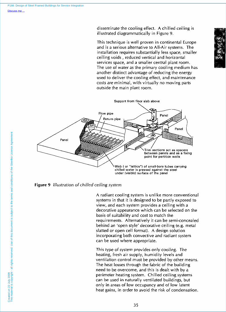
disseminate the cooling effect. A chilled ceiling is illustrated diagrammatically in Figure 9.
This technique is well proven in continental Europe and is a serious alternative to All-Air systems. The installation requires substantially less space, smaller ceiling voids , reduced vertical and horizontal services space, and a smaller central plant room. The use of water as the primary cooling medium has another distinct advantage of reducing the energy used to deliver the cooling effect, and maintenance costs are minimal, with virtually no moving parts outside the main plant room.
Support from floor slab above
tions act as spacers panels and as a fixing
Web ( or ''lattice") of small-bore tubes carrying chilled water is pressed against the steel under (visible) surface of the panel
Figure 9 Illustration of chilled ceiling system
A radiant cooling system is unlike more conventional systems in that it is designed to be partly exposed to view, and each system provides a ceiling with a decorative appearance which can be selected on the basis of suitability and cost to match the requirements. Alternatively it can be semi-concealed behind an 'open style' decorative ceiling (e.g. metal slatted or open cell format). A design solution incorporating both convective and radiant system can be used where appropriate.
This type of system provides only cooling. The heating, fresh air supply, humidity levels and ventilation control must be provided by other means. The heat losses through the fabric of the building need to be overcome, and this is dealt with by a perimeter heating system. Chilled ceiling systems can be used in naturally ventilated buildings, but only in areas of low occupancy and of low latent heat gains, in order to avoid the risk of condensation.
35
P166: Design of Steel Framed Buildings for Service Integration
Discuss me ...C
reat
ed o
n 22
Jul
y 20
09T
his
mat
eria
l is
copy
right
- a
ll rig
hts
rese
rved
. Use
of t
his
docu
men
t is
subj
ect t
o th
e te
rms
and
cond
ition
s of
the
Ste
elbi
z Li
cenc
e A
gree
men
t

INTERFACES Chilled ceilings can lead to a reduced ceiling void, but spatial allowance must also be made for separate fresh air ventilation ducts, which reduces the benefits of this system. An extract ventilation system should also be provided. The ventilation system is an integral part of chilled ceiling systems so that humidity levels are controlled, and condensation on the chilled ceiling is avoided.
Chilled beams are a variant of this system which also introduce recirculated cooled air to the space. An example of a chilled beam unit i s shown in Figure 10. As its name suggests, it is a linear rather than flat element. The cooling capacity obtainable from a chilled beam is increased when used in combination with the supply air. In this case, a separate air extract system is required.
Air supply
$>
Return air
Figure 10 Illustration of a chilled beam
36
P166: Design of Steel Framed Buildings for Service Integration
Discuss me ...C
reat
ed o
n 22
Jul
y 20
09T
his
mat
eria
l is
copy
right
- a
ll rig
hts
rese
rved
. Use
of t
his
docu
men
t is
subj
ect t
o th
e te
rms
and
cond
ition
s of
the
Ste
elbi
z Li
cenc
e A
gree
men
t

The advantages of chilled ceilings and chilled beams are:
Reduced ceiling voids.
Ceiling panels can provide a decorative finish.
Reduced energy use due to the use of high air temperatures whilst achieving the required comfort level.
Low maintenance costs.
Chilled beams may fit between the ribs of concrete slabs.
Chilled beams may incorporate fresh air-supply through ductwork.
The disadvantages of chilled ceilings or chilled beams are:
Possibility of condensation on the cooling elements and pipework, particularly in naturally ventilated spaces.
Additional fresh air supply is required in a sealed building, which leads to further ductwork.
Risks of water leaks in the occupied space.
4.1 0 Comparison of Systems
The relative merits of all the above systems are best presented in a tabular form. Table 4 describes the main design criteria, and Table 5 addresses the features of their installation and maintenance.
The different types of VAV and Fan Coil Systems and their distribution system and terminal units are illustrated in Figures 11 and 12.
37
P166: Design of Steel Framed Buildings for Service Integration
Discuss me ...C
reat
ed o
n 22
Jul
y 20
09T
his
mat
eria
l is
copy
right
- a
ll rig
hts
rese
rved
. Use
of t
his
docu
men
t is
subj
ect t
o th
e te
rms
and
cond
ition
s of
the
Ste
elbi
z Li
cenc
e A
gree
men
t

Table 4 Relative merits of heatinglventilationlcooling systems - design aspects
The following tables demonstrates some of the key factors in the design of the main 'air-conditioning' systems
System Provision Maximum Maximum lowest Comfortable Equipment Impact on Air Quality Localised of Useable/ lnspace Operating Working Life and Aesthetics Provided Control Heating, Lettable Flexibility Costs Environment Replace- of Room Options Cooling, Floor /User Control ment Costs Humidity Space
ALL AIR
Constant Volume/ Single Zone
Constant Volume/ Multi-Zone
VAV with Perimeter Heating
VAV Under-floor
VAV with Fan Assisted Boxes
AIWATER
Airmater Induction
ALL WATER
Fan Coil - Horizontal
Fan Coil - Vertical
Fan Coil - Variable Air
___.___
Supply
Chilled Ceiling
Heat Pump - Vertical Units at Perimeter
REFRIGERANT
Multiple Cassette (VRV)
Wall Mounted Package
Roof Mounted Packaae
1 2 3 2 1 2 1 3 1
1
1
1
1 ~
1 -
l
1
2
3
1
3
3
2
2 1 2
l 3
2 1
2 2 . -.
2 -
3 2 3 2 -
2 3 -
3 2
2 3 2
3 1 2
-
2 3
3 3
2 3
3 1
3 1
3 3
1 - very good
3 - average Notes: All VAV systems require some perimeter heating to offset fabric heat losses.
2 - good
38
P166: Design of Steel Framed Buildings for Service Integration
Discuss me ...C
reat
ed o
n 22
Jul
y 20
09T
his
mat
eria
l is
copy
right
- a
ll rig
hts
rese
rved
. Use
of t
his
docu
men
t is
subj
ect t
o th
e te
rms
and
cond
ition
s of
the
Ste
elbi
z Li
cenc
e A
gree
men
t

Table 5 Relative merits of heatinglventilatinglcooling systems - installation aspects
The following table demonstrates some of the key factors in the installation and maintenance of each of the main ‘air-conditioning’ systems (refer also to Table 4).
System Minimum Plant Extent of Vertical Window System Water Ease of Ease of Ceiling Room Ductwork Service Sill Electrical Pipework Extension Maintenance depth Space Shaft Heights Distribution Distribution and of Equipment
Adaption
ALL AIR
Constant Volume/ 3 3 3 3 1 1 1 3 1 Single Zone
Constant Volume/ 3 3 3 3 1 1 2 3 1 Multi-Zone
VAV with Perimeter 2 3 2 2 2 1 2 3 2 Heating
VAV Under-floor l 3 2 2 1 1 1 2 1
VAV with Fan Assisted Boxes 3 2 2 2 1 3 2 2 3
A I M A T E R
Airmater Induction 1 2 1 1 3 3 3 1 3
ALL WATER
Fan Coil - Horizontal 2 1 1 1 1 3 3 1 3
Fan Coil - Vertical 1 1 2 2 3 2 2 1 2
Fan Coil - Variable Air 2 l 1 1 1 2 2 1 3 Supply
Chilled Ceiling 1 2 1 1 1 1 3 2 2
Heat Pump - Vertical Units at 1 1 1 1 3 3 3 1 2 Perimeter
REFRIGERANT
Multiple Cassette (VRV) 2 1 1 l 1 3 1 1 3
Wall Mounted Package 1 1 1 1 3 3 1 1 3
Roof Mounted Package 2 3 3 1 1 1 1 1 1
1 - very good
3 - average Notes: All VAV systems require some perimeter heating to offset fabric heat losses. The refrigerant systems use minimal
2 - good
local ventilation.
39
P166: Design of Steel Framed Buildings for Service Integration
Discuss me ...C
reat
ed o
n 22
Jul
y 20
09T
his
mat
eria
l is
copy
right
- a
ll rig
hts
rese
rved
. Use
of t
his
docu
men
t is
subj
ect t
o th
e te
rms
and
cond
ition
s of
the
Ste
elbi
z Li
cenc
e A
gree
men
t

INTERFACES
HIGH VELOCITY SUPPLY AIR DUCTWORK
DAMPER CONTROL TO
-
VARY THE VOLUME OF COOL AIR DELIVERED TO THE SPACE
COLUMN I/ ' G FLEXIBLE DUCTWORK CONNECTION
l A
L
l 1
l
l
EXTRACT AIR THROUGH LIGHT FITTINGS, EXTRACT CEILING PLENUM & INTO EXTRACT STUB DUCTWORK
LOW VELOCITY EXTRACT DUCTWORK
PERIMETER SUPPLY DUCT HEADER
Variable Air Volume boxes with perimeter heating Units are installed in the ceiling void and chilled air is ducted to them. Air is extracted by a separate duct back to the central plant. The perimeter heating system can take the form of radiators, convectors or sill-line heating grilles. The central plant comprises boilers and refrigeration equipment, which provides heating and cooling respectively to the central air handling units.
l
Figure 11 Variable Air Volume system
showing the distribution system and terminal units
40
P166: Design of Steel Framed Buildings for Service Integration
Discuss me ...C
reat
ed o
n 22
Jul
y 20
09T
his
mat
eria
l is
copy
right
- a
ll rig
hts
rese
rved
. Use
of t
his
docu
men
t is
subj
ect t
o th
e te
rms
and
cond
ition
s of
the
Ste
elbi
z Li
cenc
e A
gree
men
t

EXTRACT OUCTWORK
FRESH AIR SUPPLY OUCTWORK
4 PIPE FAN COIL UNIT PROVIDING HEATING & L 1 COOLING I\
FLEXIBLE OUCTWORK \ .
CONNECTION
I
I ~
I
l
150mm RAISED FLOOR
130mm COMPOSITE SLAB
406mm BEAM
314mm VOID
200mm LIGHTING ZONE AN0 TOLERANCE
PERIMETER SUPPLY AIR SLOT DIFFUSER & PLENUM BOX LIGHT FITTINGS CEILING PLENUM & INTO
ROOM AIR RETURNS TO FAN COIL VIA
EXTRACT AIR THROUGH LIGHT FITTINGS, EXTRACT
EXTRACT STUB OUCTWORK
COLUMN 4
CONDENSATE DRAIN TO F A L L S
Horizontal Fan Coil Unit Fan Coil Units are installed in the ceiling void where they are supplied with hot and chilled water from centrally located boilers and refrigeration plant. A separate air handling unit introduces external air directly into the Fan Coil Unit for ventilation. Air is extracted by a separate duct back to the central plant. Locally mounted controls sequence the heating and cooling delivered by the Fan Coil Unit to maintain the desired room conditions.
F&R
Figure 12 Fan Coil Unit system
showing the distribution system and terminal units
41
P166: Design of Steel Framed Buildings for Service Integration
Discuss me ...C
reat
ed o
n 22
Jul
y 20
09T
his
mat
eria
l is
copy
right
- a
ll rig
hts
rese
rved
. Use
of t
his
docu
men
t is
subj
ect t
o th
e te
rms
and
cond
ition
s of
the
Ste
elbi
z Li
cenc
e A
gree
men
t

INTERFACES
42
P166: Design of Steel Framed Buildings for Service Integration
Discuss me ...C
reat
ed o
n 22
Jul
y 20
09T
his
mat
eria
l is
copy
right
- a
ll rig
hts
rese
rved
. Use
of t
his
docu
men
t is
subj
ect t
o th
e te
rms
and
cond
ition
s of
the
Ste
elbi
z Li
cenc
e A
gree
men
t

5 INTERNAL DISTRIBUTION OF SERVICES
For many reasons, ranging from planning height restrictions to maximising the net lettable area of commercial office building, there is pressure to minimise the space allocated to the building services. Therefore, it is necessary to ensure an efficient use of space for the service distribution system and in the plant rooms.
The following Sections review the spatial aspects of the vertical and horizontal service distribution.
43
P166: Design of Steel Framed Buildings for Service Integration
Discuss me ...C
reat
ed o
n 22
Jul
y 20
09T
his
mat
eria
l is
copy
right
- a
ll rig
hts
rese
rved
. Use
of t
his
docu
men
t is
subj
ect t
o th
e te
rms
and
cond
ition
s of
the
Ste
elbi
z Li
cenc
e A
gree
men
t

INTERFACES 5.1 General Recommendations
General recommendations@) on the location of central plant rooms are as follows:
Ensure that plant rooms are not separated from vertical service routes (risers) by difficult or restrictive distribution routes. Passing major services through a narrow corridor is not recommended.
Position vertical routes for services at the boundary of the plant room. A riser that passes through the middle of the plant room effectively renders large areas of the plant room unusable.
Avoid services crossing a major fire barrier.
Take account of the building form (Sections 5.2 to 5.4).
5.2 Vertical Distribution of Services
The following recommendations apply to the vertical distribution of services:
Provide continuous and uninterrupted vertical service routes.
Maintain a constant cross-section of the service route. Lift shafts are always designed as constant dimension elements - apply the same principle to service routes.
Position the plant room so that it is as close as possible to the centre of the plan area it serves.
Consider the connection between horizontal services and vertical services routes.
Provide separate routes for different services. The minimum is two; one for electrics and one for water pipes etc., although most buildings require more service routes.
Horizontal distribution should ideally not extend more than 25 m from a vertical service route. Longer distances wi l l impose penalties on the system design and increase the depth of horizontal service ducts.
Position plant rooms at no more than 10 storeys apart vertically.
44
P166: Design of Steel Framed Buildings for Service Integration
Discuss me ...C
reat
ed o
n 22
Jul
y 20
09T
his
mat
eria
l is
copy
right
- a
ll rig
hts
rese
rved
. Use
of t
his
docu
men
t is
subj
ect t
o th
e te
rms
and
cond
ition
s of
the
Ste
elbi
z Li
cenc
e A
gree
men
t

l
Small building (up to four storeys and up to 2 5 0 0 m’ total f loor area)
I I
I Large plan building (4000 m2 total f loor area)
Large, tall building (over 15 storeys)
L-shaped building (1000 m 2 t o 3000 m2 per floor) (3 -10 storeys)
Building with atr ium (typically 2000 m’ per floor)
Examples of these recommendations applied to typical building forms are shown in Figures 13 and 14.
Plan
61 I Plant room
E 150 m
E l K-- 60 m
i( 4 60 m
Notes
One plant room, one riser Location of riser not important, due to small size of building (central location preferred). Plant room must be adjacent to the riser.
~~
Several plant rooms adjacent to areas served. Some central plant, for example for gas intake and boilers, may be required.
Plant room floors at basement and roof level. Intermediate plant rooms may be required. Vertical distribution within central core.
Several plant ro’oms, several risers. Risers and air plant rooms adjacent t o cores. Separate room located at ground/basement level for new electric supply.
Four roof air plant rooms, one basement plant room. Four risers related to cores. Basement plant below atrium gives best connection to risers.
Figure 13 Typical arrangements of plant rooms and vertical service routes (taken from Reference (S))
45
P166: Design of Steel Framed Buildings for Service Integration
Discuss me ...C
reat
ed o
n 22
Jul
y 20
09T
his
mat
eria
l is
copy
right
- a
ll rig
hts
rese
rved
. Use
of t
his
docu
men
t is
subj
ect t
o th
e te
rms
and
cond
ition
s of
the
Ste
elbi
z Li
cenc
e A
gree
men
t

INTERFACES
L
Location
Effects of riser location on duct depth.
Example building, 40 m x 40 m, with air duct riser located (a) centrally, (b) a t a corner.
The longer the duct, the deeper it is where it joins the riser (and hence increased depth of ceiling/floor zone) The examples show that with a central riser, ducts can be shorter and so shallower.
Typical ductwork layout in ceiling void
V I V
\ /
Duct
I /
maximum duct depth 400 maximum duct depth 600
V V
Relationship of vertical riser location to duct size and distribution
Figure 14 Key aspects o f efficient duct distribution (taken from Reference (8))
5.3 Ceiling Grids
In heavily serviced buildings, it is often the case that air griIIes/diffusers, sprinklers, luminaries and smoke detectors can all be usefully placed in the same location on the ceiling. A modular layout of the ceiling area is required in order to provide a defined space for each element on plan. This involves the sub-division of the ceiling into a regular grid pattern.
The dimension of this ceiling grid has, with experience, been regulated to 1200 mm, 1500 mm or 1800 mm. Multiples of these grid dimensions are suitable office space and structural grid dimensions. Typically 1200 mm or 1500 mm have become common structural grid dimensions.
The grid dimensions allow an economic selection and distribution of light fittings and linear air diffusers. Sub-division of the grid dimension by 600 mm or 300 mm leads to sensible ceiling tile
46
P166: Design of Steel Framed Buildings for Service Integration
Discuss me ...C
reat
ed o
n 22
Jul
y 20
09T
his
mat
eria
l is
copy
right
- a
ll rig
hts
rese
rved
. Use
of t
his
docu
men
t is
subj
ect t
o th
e te
rms
and
cond
ition
s of
the
Ste
elbi
z Li
cenc
e A
gree
men
t

dimensions and the possible use of square lights and diffusers. Figure 15 shows tvpical linear air diffusers and lighting units located within a modular ceiling panel.
Figure 15 Example of air diffusers located in lighting units
5.4 Horizontal Distribution of Services
Conventionally, the horizontal distribution of services is arranged within a horizontal layer which is generally located below the structure. This layer accommodates both the distribution system (ducts, pipes etc), the terminal units and lighting units. The raised floor is placed on the floor slab and accommodates the electrical and communication cabling. The lighting units are often located within the ceiling depth.
To determine the spatial allowance for these elements, three dejign cases may be envisaged corresponding to different structural configurations: 1. A flat slab with flexibility of service routing.
2. A slab and downstand beam arrangement.
3. A long,span beam system with facility for service integration.
47
P166: Design of Steel Framed Buildings for Service Integration
Discuss me ...C
reat
ed o
n 22
Jul
y 20
09T
his
mat
eria
l is
copy
right
- a
ll rig
hts
rese
rved
. Use
of t
his
docu
men
t is
subj
ect t
o th
e te
rms
and
cond
ition
s of
the
Ste
elbi
z Li
cenc
e A
gree
men
t

INTERFACES In case 1, the ducts pass within the depth allowed for the terminal units. However, cross-overs of ducts must be avoided in order to minimize this depth. In cases 2 and 3, the terminal units may be located between the beams, which means that additional space below the beams is required only for the major ducts, ceiling and l ightkg units. In case 3, the ducts are located entirely within the structural zone.
Typical dimensional allowances for service zones in typical modern air-conditioned buildings are presented in Table 6 for these three cases. It can be seen that the dimensions allowed for the various components lead to ceiling-floor depths of 1100 mm to 1250 mm. The differences between the flat soffit and the long span systems with integrated services are relatively small in terms of overall ceiling-floor depths. The comparable ceiling-floor depths for a non-air-conditioned building would be 650 mm, 875 mm and 1250 mm respectively for the three cases, and the differences between the systems are obviously much greater.
Tab'e Vertical Dimension for the Flat Downstand Long Span Typical VeftiCaI Following Components: Soffit Beams Beams
dimensions between (mm) (mm) (mm) Ceiling and floor 1. Allowance for deflection 25 50 75
2. Lighting units and ceiling 175 125 125
and fire protection
(units located between the beams)
3. VAV box and attachments 450 nil nil (boxes between beams)
4. Ducts and insulation < 4 5 0 2 5 0 ( + 75 nil insulation)
TOTAL (below structure) 650 500 200
5. Raised floor 150 150 150
6. Structural depth (typical) 300 550 900 TOTAL (ceiling-floor) 1100 1200 1250
___
Note: These approximate dimensions may be used for planning purposes.
It i s possible to reduce these ceiling-floor depths, but the cost of the structure, and services (due to inefficient duct shapes, or number of separate ducts) may increase. For example, some of the structural systems investigated in Section 7 achieve depths varying by 100 mm from these approximate dimensions.
48
P166: Design of Steel Framed Buildings for Service Integration
Discuss me ...C
reat
ed o
n 22
Jul
y 20
09T
his
mat
eria
l is
copy
right
- a
ll rig
hts
rese
rved
. Use
of t
his
docu
men
t is
subj
ect t
o th
e te
rms
and
cond
ition
s of
the
Ste
elbi
z Li
cenc
e A
gree
men
t

6 STRUCTURAL OPTIONS FOR SERVICES INTEGRATION
The following sections describe the main structural systems that may be used in steel framed commercial buildings, concentrating on the long span systems that have been developed. All the systems described use composite floor slabs.
6.1 Composite Construction
In composite construction, steel beams act structurally with an in situ and lightly reinforced concrete slab on steel decking, which is used as permanent f o r m w ~ r k ( ~ , ~ ) . Shear connectors are used
49
P166: Design of Steel Framed Buildings for Service Integration
Discuss me ...C
reat
ed o
n 22
Jul
y 20
09T
his
mat
eria
l is
copy
right
- a
ll rig
hts
rese
rved
. Use
of t
his
docu
men
t is
subj
ect t
o th
e te
rms
and
cond
ition
s of
the
Ste
elbi
z Li
cenc
e A
gree
men
t

INTERFACES to develop composite action between the concrete slab and the steel beams. All materials act together 'compositely', after the concrete has gained sufficient strength, to provide a strong, efficient method of floor construction.
The main reasons for using composite construction are economic, i n most instances. Faster erection of the steel frame, and the elimination of temporary propping of the slab, facilitates earlier completion of the building, which in turn reduces interest charges and advances rental income. There are also significant savings in use of steel, as a composite beam may be twice the strength of the equivalent non-composite beam in conventional steelwork, and up to four times stiffer. This means that shallower structural depths can be achieved which permits use of lower storey heights and leads to savings in cladding costs, or alternatively, provides more space or flexibility for services within the same overall floor-to-floor height.
6.2 Slim Floors and Slimdek
Slim floors (also called integrated beams in some countries) have been specifically developed to achieve minimum structural depth and therefore provide maximum flexibility for distribution of services beneath the f l ~ o r ' ~ , ' ~ ) . The beam consists of an H section (usually UC) with a welded bottom plate. The registered British Steel trademark is Slimflor in the UK. Two alternative floor systems may be used: either precast concrete (pc) units, or a deep deck composite slab. Both elements are supported by the plate in order to form a flat soffit. The Slimflor beam using deep decking is illustrated in Figure 16. Small openings may be formed in the web of the section for pipes and small ducts. The space between the ribs may also be utilized for fitments and cross-overs of ducts.
Recently, British Steel has launched the Slimdek system("!'*' which comprises a rolled asymmetric beam (ASB) used with a deep deck composite slab. This new form of construction is illustrated in Figure 17. The ASB can be up to 25% lighter than the equivalent Slimflor beam, and requires much less fabrication. The Slimdek system is considered as a variant of the slim floor system in this study, and it increases the economy of this form of construction.
50
P166: Design of Steel Framed Buildings for Service Integration
Discuss me ...C
reat
ed o
n 22
Jul
y 20
09T
his
mat
eria
l is
copy
right
- a
ll rig
hts
rese
rved
. Use
of t
his
docu
men
t is
subj
ect t
o th
e te
rms
and
cond
ition
s of
the
Ste
elbi
z Li
cenc
e A
gree
men
t
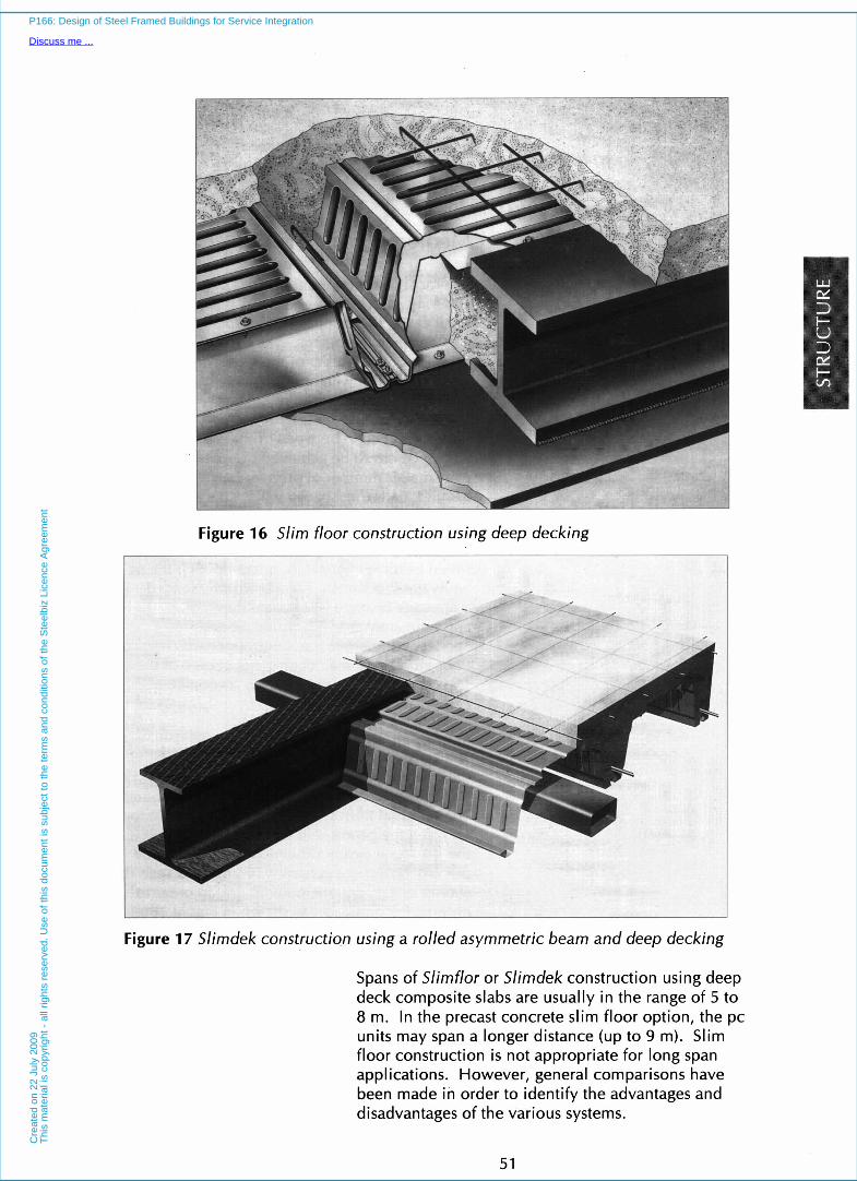
Figure 16 Slim floor construction using deep decking
Figure 17 Slimdek construction using a rolled asymmetric beam and deep decking
Spans of Slimflor or Slimdek construction using deep deck composite slabs are usually in the range of 5 to 8 m. In the precast concrete slim floor option, the pc units may span a longer distance (up to 9 m). Slim floor construction is not appropriate for long span applications. However, general comparisons have been made in order to identify the advantages and disadvantages of the various systems.
51
P166: Design of Steel Framed Buildings for Service Integration
Discuss me ...C
reat
ed o
n 22
Jul
y 20
09T
his
mat
eria
l is
copy
right
- a
ll rig
hts
rese
rved
. Use
of t
his
docu
men
t is
subj
ect t
o th
e te
rms
and
cond
ition
s of
the
Ste
elbi
z Li
cenc
e A
gree
men
t

INTERFACES Slim floor and Slirndek construction wi l l be beneficial either in highly serviced buildings, where maximum flexibility of service distribution is required, or in buildings without air-conditioning, in which the floor depth is minimised.
6.3 Medium Span systems
The most common framing plans used in medium and long span buildings are illustrated in Figure 18. In all cases, the composite slab spans typically 3 to 4 m between the beams. The upper limit often depends on the ability of the steel decking to safely support the wet weight of concrete during the construction stage without temporary propping. Secondary beams are used to support the slab and these beams span between primary beams. Clearly, a balance has to be achieved between the provision of a smaller number of primary beams supporting heavier loads (i.e. spaced wider apart), and a greater number of more lightly loaded beams.
Medium span systems generally use standard hot rolled beam sections (UB, or continental IPE or equivalent sections). For a uniformly loaded composite beam, a steel beam depth of approximately span/25 would be required. Serviceability limits (i.e. control of deflections or floor vibrations) may control the choice of the steel section rather than the bending resistance of the composite section.
In medium span systems, no attempt is usually made to achieve full services integration, and the depths of the primary and secondary beams are selected so that the services distribution systems pass beneath. The terminal units in the services system are located between the beams, either partly or wholly within the structural depth. The more heavily loaded primary beams are generally arranged to span the shorter distance in the column grid in order to minimize their depth, as shown in Figure 18(a).
52
P166: Design of Steel Framed Buildings for Service Integration
Discuss me ...C
reat
ed o
n 22
Jul
y 20
09T
his
mat
eria
l is
copy
right
- a
ll rig
hts
rese
rved
. Use
of t
his
docu
men
t is
subj
ect t
o th
e te
rms
and
cond
ition
s of
the
Ste
elbi
z Li
cenc
e A
gree
men
t

H 6
l Primary beam (span 5 - 8 m)
2.5 - 4 m
'H H Secondary beam (span 6 - 12 m)
(a) Typical framing plan for medium span beams
Primary beam (man 12 - 18 m)
(b) Typical framing plan for long span beams
Figure 18 Typical framing plans for medium and long span beams
6.4 Long Span Construction
Building users and developers are increasingly demanding more column-free space, and 12 to 18 m column spacings have become more popular. Agents find that column-free spaces easier to let and may well command a rent premium. A variety of structural solutions for long spans, (i.e. above 9 m) wil l be considered in the following Sections. A typical framing plan is shown in Figure 18(b).
One of the principal advantages of steel over concrete construction is i ts ability to span further with less use and weight of materials. However, costs per square metre increases as the column spacing increases, although these additional costs may be small in comparison to the economic and functional benefits realised from greater areas of uninterrupted usable floor space. Internal columns are often unwelcome, particularly when they become large in cross-section due to their high loading in tall buildings.
53
P166: Design of Steel Framed Buildings for Service Integration
Discuss me ...C
reat
ed o
n 22
Jul
y 20
09T
his
mat
eria
l is
copy
right
- a
ll rig
hts
rese
rved
. U
se o
f th
is d
ocum
ent
is s
ubje
ct t
o th
e te
rms
and
cond
ition
s of
the
Ste
elbi
z Li
cenc
e A
gree
men
t

INTERFACES Fabricated tapered girders, haunched beams, parallel beam systems, composite trusses, stub girders and cellular beams are examples of modern long span structural systems, which are described in detail in the following Sections.
The optimum structural solution depends on the:
spans of the primary and secondary beams. Often the long span beam is used as the primary beam, as shown in Figure 18(b)
span/depth ratio of the members
necessity to contribute to the resistance to lateral loads applied to the building
location and cross-sectional area of major ducts across the span (including consideration of general distribution routes and crossover positions) ‘looseness of fit’ between services and structure, (especially important for ‘shell and core’ developments, where particular tenants may require additional provisions)
structure cost (including the savings on cladding and other costs).
Since it is now almost inevitable that building services wi l l change significantly during the life of a commercial building, the designer should take future adaptability into account when selecting the structural system to be used.
The different long span alternatives that may be considered and their span capabilities are presented in Table 7. These data are for guidance only, as many of the systems can be used over a much greater range of application. Also shown in Table 7 are the comparable medium span systems in steel and concrete construction.
54
P166: Design of Steel Framed Buildings for Service Integration
Discuss me ...C
reat
ed o
n 22
Jul
y 20
09T
his
mat
eria
l is
copy
right
- a
ll rig
hts
rese
rved
. Use
of t
his
docu
men
t is
subj
ect t
o th
e te
rms
and
cond
ition
s of
the
Ste
elbi
z Li
cenc
e A
gree
men
t

Table 7 Summary of typical spans of different structural systems in steel and concrete construction
Span (m) 20 16 13 10 a 6
Reinforced concrete (r.c.1 flat slab
Slirndek with deep composite slab
R.C. waffle slab 1 I
I
Shelf angle beam with precast slabs
Slirnflor with precast slabs I I
I R.C. beam and slab I I I I I I Post-tensioned concrete flat slab
Composite beam and slab I
l
Parallel beam approach
Composite beam with web openings I
I Cellular composite beam
I Tapered girder
I I
Haunched composite beam
Composite truss
Note: Minimum and maximum spans are given for general guidance of the capabilities of each system.
6.5 Composite Beams with Web Openings
Reserve capacity exists over much of the length of a standard beam section and this wi l l permit rectangular or circular openings to be cut in the web, provided these openings are located away from the supports. Relatively large openings can usually be provided without the need for strengthening by horizontal stiffeners, provided that there is adequate shear resistance in the remaining web. A typical web opening suitable for a large rectangular duct is shown in Figure 19. The high degree of composite action around the openings means that the loss of bending resistance of the beam due to the web openings i s often not as significant as in a steel beam.
55
P166: Design of Steel Framed Buildings for Service Integration
Discuss me ...C
reat
ed o
n 22
Jul
y 20
09T
his
mat
eria
l is
copy
right
- a
ll rig
hts
rese
rved
. Use
of t
his
docu
men
t is
subj
ect t
o th
e te
rms
and
cond
ition
s of
the
Ste
elbi
z Li
cenc
e A
gree
men
t

INTERFACES
Figure 19 Openings in the webs of composite beams
If larger service zones are necessary, more costly ‘stiffened’ openings are required. Circular openings are more efficient structurally than rectangular openings, but are usually less practical- as they are generally smaller in area. By deepening the primary beams, and forming larger openings, the flexibility of service distribution can be increased.
However, a major disadvantage of this simple option is the relative inflexibility of the system. Openings ‘tailored’ to meet the requirements of a particular service installation provide little scope for future changes in service layout. Furthermore, after a beam size has been selected, it may be impossible to accommodate even a slight increase in duct size without increasing the beam depth.
When locating rectangular openings in the webs of composite beams, the following g~idelined’~) should be considered:
Openings should not be located closer than two times the beam depth D from the support, or 1Ooh of the span, whichever is the greater.
The best location for any opening is between 1/5 and 113 of the span from a support in uniformly loaded beams.
For beams subject to point loads, the location of the openings depends on the relative importance of moment and shear along the beam.
5 6
P166: Design of Steel Framed Buildings for Service Integration
Discuss me ...C
reat
ed o
n 22
Jul
y 20
09T
his
mat
eria
l is
copy
righ
t -
all r
ight
s re
serv
ed.
Use
of
this
doc
umen
t is
sub
ject
to
the
term
s an
d co
nditi
ons
of t
he S
teel
biz
Lice
nce
Agr
eem
ent

Openings should not be less than the beam depth, D, apart.
Unstiffened openings should not generally be deeper than 0.6 D, nor longer than 1.5 D. The shear resistance and instability of the web should be checked.
Stiffened openings should not generally be deeper than 0.7 D, nor longer than 2 D. Stiffeners should be in the form of horizontal plates welded above and below the opening.
Point loads should not be applied at less than D from the side of the adjacent opening.
As an alternative near supports, beams may be notched by cutting away the lower part of the beam web and flange. As much as half of the beam depth, D, can be removed extending up to distance D into the span. This permits the use of modest service zones adjacent to the supports of long span beams.
6.6 Cellular and Caste1 lated Beams
For long spans, a deep beam is often required in order to provide adequate stiffness. In the standard range of rolled sections, flange and web thicknesses increase with beam depth. These sections are adapted to non-composite applications, but are often heavier than needed when acting as composite beams.
Lighter deeper sections can be fabricated from structural sections in the form of castellated or ‘cellular’ beams(14). These sections are produced by cutting standard sections and re-welding in a particular pattern to create deeper beams with a series of hexagonal or circular holes. A castellated beam is shown in Figure 20.
The sections are structurally efficient, and relatively large openings can be created through which services can be passed. The numerous openings through the web provide good flexibility for future re-servicing, although the finite size of the openings may restrict the duct sizes that can be used.
57
P166: Design of Steel Framed Buildings for Service Integration
Discuss me ...C
reat
ed o
n 22
Jul
y 20
09T
his
mat
eria
l is
copy
right
- a
ll rig
hts
rese
rved
. Use
of t
his
docu
men
t is
subj
ect t
o th
e te
rms
and
cond
ition
s of
the
Ste
elbi
z Li
cenc
e A
gree
men
t

INTERFACES
l!
Figure 20 Castellated beam
Castellated and ‘cellular beams’ are more suitable for use as long span secondary beams than for primary beams with point loads, as the shear capacity of the web is considerably weakened by the openings. However, they can be designed for use as primary members by strengthening the openings where shear forces are very high, either by infilling the openings or by using horizontal stiffeners, although this adds considerably to the fabrication costs.
Castellated beams formed from structural sections have an overall depth, D, 50% greater than the parent beam. Standard castellations comprise hexagonal holes of maximum depth 0.67 D at 0.72 D centres which would allow the passage of circular ducts of up to 0.4 D diameter. The loss of the beam web reduces i ts bending and shear strength. Typical span/depth ratios are approximately 20.
For ’cellular beams’, a wide range of opening sizes and beam sizes is possible, although the diameter and spacing of openings must be constant along the length of a beam. Circular openings can be created with diameters of 0.6 to 0.8 times the final beam depth and at spacings of 1 .l to 1.5 times the opening diameter. Furthermore, in some cases, the openings may be enlarged by removing the ‘web post’ separating two adjacent openings. This can be
58
P166: Design of Steel Framed Buildings for Service Integration
Discuss me ...C
reat
ed o
n 22
Jul
y 20
09T
his
mat
eria
l is
copy
right
- a
ll rig
hts
rese
rved
. Use
of t
his
docu
men
t is
subj
ect t
o th
e te
rms
and
cond
ition
s of
the
Ste
elbi
z Li
cenc
e A
gree
men
t

achieved in the middle third of the span, though additional stiffening is generally required.
A cellular beam may also be formed by welding two different sections together. For composite beam design, where the concrete slab acts in compression, the top flange may be significantly reduced in size. A combination of different UB and UC sections (or continental IPE and HE sections) can reduce the weight of a beam by up to 30°/0, whilst providing the same composite stiffness as a solid beam of the same depth. The production process for cellular beams also allows the sections to be pre-cambered during production, effectively overcoming deflection problems due to self weight.
The ability of cellular beam to accommodate a large number of circular ducts is illustrated in Figure 21.
. Cellular beams are often used where a high degree of flexibility in service routing is required. The structural properties of cellular beams lend themselves to use as both secondary and primary beams. These alternative configurations are considered in the later sections of this publication. There are a growing number of buildings where this form of construction has been used to provide a highly serviced and visually attractive floor system.
Figure 21 Cellular beam showing distribution of circular ducts
59
P166: Design of Steel Framed Buildings for Service Integration
Discuss me ...C
reat
ed o
n 22
Jul
y 20
09T
his
mat
eria
l is
copy
right
- a
ll rig
hts
rese
rved
. Use
of t
his
docu
men
t is
subj
ect t
o th
e te
rms
and
cond
ition
s of
the
Ste
elbi
z Li
cenc
e A
gree
men
t

INTERFACES 6.7 Haunched Beams
Haunching of beams to reduce the rafter depth is standard practice in portal frame structures. Haunches, or local deepening of the beam adjacent to the beam to column connection, can also be used to reduce beam depths for long span By providing a rigid connection at the beam ends, the bending moment at mid-span can be considerably reduced and a smaller steel section used. The beam may also be designed to act compositely with the floor slab in the mid-span zone. This system is illustrated in Figure 22.
Large moments are transferred into the columns, resulting in more expensive connections and heavier columns. In long span, low rise buildings this may result in reduced frame costs, as the total beam length and weight are significantly greater than the column length and weight. Haunched beams can also be designed to provide the sway stability of the building without requiring vertical bracing.
Figure 22 Haunched composite beam
The rigid connections at the ends of haunched beams also considerably stiffen the beam and reduce deflections. Therefore, span/beam depth ratios can be increased to around 35, corresponding to about 30% reduction in beam depth relative to simply
60
P166: Design of Steel Framed Buildings for Service Integration
Discuss me ...C
reat
ed o
n 22
Jul
y 20
09T
his
mat
eria
l is
copy
right
- a
ll rig
hts
rese
rved
. Use
of t
his
docu
men
t is
subj
ect t
o th
e te
rms
and
cond
ition
s of
the
Ste
elbi
z Li
cenc
e A
gree
men
t

supported beams. The critical section for design is the beam at the tip of the haunch. The length of the haunch is selected to achieve an efficient moment connection to the column. A haunch cut from the same section (of depth D) i s usually used, resulting in an overall depth at the supports of approximately 2 D. Consequently, a clear zone of depth D i s produced across approximately 85% of the beam span.
A shallow beam depth therefore permits the services to be passed beneath both the primary and secondary beams within the depth of the haunches. Apart from zones adjacent to column lines, the haunched beam solution offers almost total flexibility for service layout. This gives greater freedom in design of the service layout and easier installation on site.
Despite these advantages, the haunched beam solution requires careful structural design because the beams must frame into the major axis of columns in order to transfer moments to the columns. The haunched beam system is ideally suited to buildings with rectangular plan form and approximately equal adjacent spans. The system is not generally appropriate for irregular building plan shapes.
6.8 Tapered Beams
As an alternative to rolled sections, fabricated steel sections produced from flat plate can be used. Additional fabrication costs can be offset against reduced material costs, resulting in a structurally efficient and economic design. Fabricated sections may be of uniform depth, but tapered beams offer advantages in highly serviced bui ld ingP. By tapering the beam along its length, the bending resistance of the section can be made to closely follows the shape of the bending moment diagram. A typical example of a tapered beam is illustrated in Figure 23.
At the ends of the beam, the depth may be reduced, depending on the required shear resistance. This saves weight of steel, but more importantly, releases space below the beam for service distributions. Thus a reasonably sized zone is created in which large services may be accommodated adjacent to the columns. Service distribution in the other direction can usually be provided in the zone beneath the secondary beams.
61
P166: Design of Steel Framed Buildings for Service Integration
Discuss me ...C
reat
ed o
n 22
Jul
y 20
09T
his
mat
eria
l is
copy
right
- a
ll rig
hts
rese
rved
. Use
of t
his
docu
men
t is
subj
ect t
o th
e te
rms
and
cond
ition
s of
the
Ste
elbi
z Li
cenc
e A
gree
men
t

INTERFACES
Figure 23 Tapered fabricated beam
In the case of fabricated steel sections, the structural engineer has the greatest freedom in the selection of section size. These beams may have straight tapers, or alternatively be semi-tapered, i.e. the beam is of uniform depth in the mid-span region. A straight taper is simpler to fabricate and, in many cases, is the most economic shape. Typical tapered girders reduce to approximately half depth at the supports with a maximum taper angle of about 6". A vertical stiffener may be required at mid-span for deeper sections. A practical range of span/depth ratios is from 15 to 25, but as the ratio increases (i.e. beam depth reduces), the material costs increase, although the variation in depth still permits more ready accommodation of services.
6.9 Composite Trusses
The use of trusses (or lattice girders) for long spans is well established in non-composite construction, but they can also be used in composite construction, where the concrete slab becomes an effective compression membeP. During construction, the truss must be capable of supporting the wet concrete and other construction loads, but after the concrete has gained strength, the top chord is no longer required to resist compressive forces.
In terms of steel weight, trusses can .be efficient, but increased fabrication costs erode much of this economy. In order to provide service zones of
62
P166: Design of Steel Framed Buildings for Service Integration
Discuss me ...C
reat
ed o
n 22
Jul
y 20
09T
his
mat
eria
l is
copy
right
- a
ll rig
hts
rese
rved
. Use
of t
his
docu
men
t is
subj
ect t
o th
e te
rms
and
cond
ition
s of
the
Ste
elbi
z Li
cenc
e A
gree
men
t

usable size, the trusses need to relatively deep. Fire protection to the diagonal members may be quite thick, and may considerably reduce the space available for services. Furthermore, fire protection can be significantly more complex and costly than for conventional beams, as illustrated in Figure 24.
L
Figure 24 Composite truss showing fire protection
Trusses can be manufactured from ‘tee’ and angle sections, or alternatively from tubular (CHS or SHS) sections. They are generally welded together to avoid the effect of cumulative bolt slip on deflections. The standard form of truss is of the Warren (W) form, which gives the greatest space between the bracing members. Cylindrical ducts are often preferred for use in trusses.
Structural hollow section (SHS) members are usually more efficient for use in long span trusses.
Composite trusses are suitable for use as secondary and primary members with spans of 12 to 20 m. Trusses placed at relatively close centres can support the slab directly. In this case local bending of the top chord must be considered. Furthermore, as web members are invariably welded to the top chord, local moments may develop in the members.
Where trusses are used as primary members, the top chord does not support the floor directly, but must support a series of point loads from secondary
63
P166: Design of Steel Framed Buildings for Service Integration
Discuss me ...C
reat
ed o
n 22
Jul
y 20
09T
his
mat
eria
l is
copy
right
- a
ll rig
hts
rese
rved
. Use
of t
his
docu
men
t is
subj
ect t
o th
e te
rms
and
cond
ition
s of
the
Ste
elbi
z Li
cenc
e A
gree
men
t

INTERFACES members. Connection of the secondary beams to the trusses wil l often require use of vertical posts at these beam locations, thus reducing the size* of openings available for services.
Shallower trusses can be achieved by confining large services to a single ’Vierendeel’ panel (a rectangular opening with no diagonals) at the centre of the span. The shear resistance across such an opening derives mainly from local composite action with the slab. Alternatively, the bracing members within a regular truss may be offset slightly to accommodate larger services zones. This can be achieved most easily at mid-span where shear forces are small. Trusses generally offer a high degree of flexibility for servicing and future adaption.
6.10 Stub Girders
Stub girders are ’Vierendeel assemblies’ consisting of a UC or HE steel section as a bottom chord and a concrete slab as a top chord18). Intermittent short lengths of a standard steel section, connected by shear studs to the concrete slab and welded to the bottom chord, act as ‘vertical web members’ to transfer longitudinal forces between the two elements. One form of stub girder construction is illustrated in Figure 25.
Figure 25. Stub girder, not requiring propping during construction (photo by Grant Smith, NCE)
64
P166: Design of Steel Framed Buildings for Service Integration
Discuss me ...C
reat
ed o
n 22
Jul
y 20
09T
his
mat
eria
l is
copy
right
- a
ll rig
hts
rese
rved
. Use
of t
his
docu
men
t is
subj
ect t
o th
e te
rms
and
cond
ition
s of
the
Ste
elbi
z Li
cenc
e A
gree
men
t

6.1 1
When the stub girders are placed wide apart, secondary beams, usually of the same depth as the stub lengths, span between the girders and may be continuous over a number of bottom chords, which improves their spanning capabilities.
The main advantage of this form of construction is that large spaces between the secondary beams and the stubs provide natural openings for the passage of services. The main disadvantage is often the need for propping during construction, as the bottom chord alone may not have sufficient strength and stiffness to support the construction loads.
To avoid this problem, a stub girder has been developed which does not require propping (see Figure 25). A Tee section top chord is provided (with i ts leg uppermost) which achieves adequate bending strength for the construction condition when combined with the bottom chord. Bar reinforcement is passed through holes in the Tee and this section is embedded in the slab. No shear connectors are required in this case.
With conventional stub girder construction, the depth of openings is generally determined by the depth of the secondary beams, and as these secondary beams may be continuous, the depth of openings may be quite small. If larger openings are required, the stubs can be cut from deeper sections and the secondary beams framed into them rather than being seated on the bottom chord.
Although widely used in North America and Canada, experience of stub girders in European practice is limited to a small number of projects in the UK. They offer good flexibility of service layout across the span, and by virtue of the number of openings, they offer scope for future re-servicing. In conventional stub girders, opening widths of approximately three times the opening depth can be used in low shear regions, reducing to twice the opening depth in high shear regions.
Para1 le1 Beam Systems
In the structural forms discussed previously, the primary members usually span the greater distance between the columns. They are therefore ideally suited to single bay buildings without internal columns. In multi-bay construction, it may be preferable to design the secondary members to span the greater distance.
65
P166: Design of Steel Framed Buildings for Service Integration
Discuss me ...C
reat
ed o
n 22
Jul
y 20
09T
his
mat
eria
l is
copy
right
- a
ll rig
hts
rese
rved
. Use
of t
his
docu
men
t is
subj
ect t
o th
e te
rms
and
cond
ition
s of
the
Ste
elbi
z Li
cenc
e A
gree
men
t
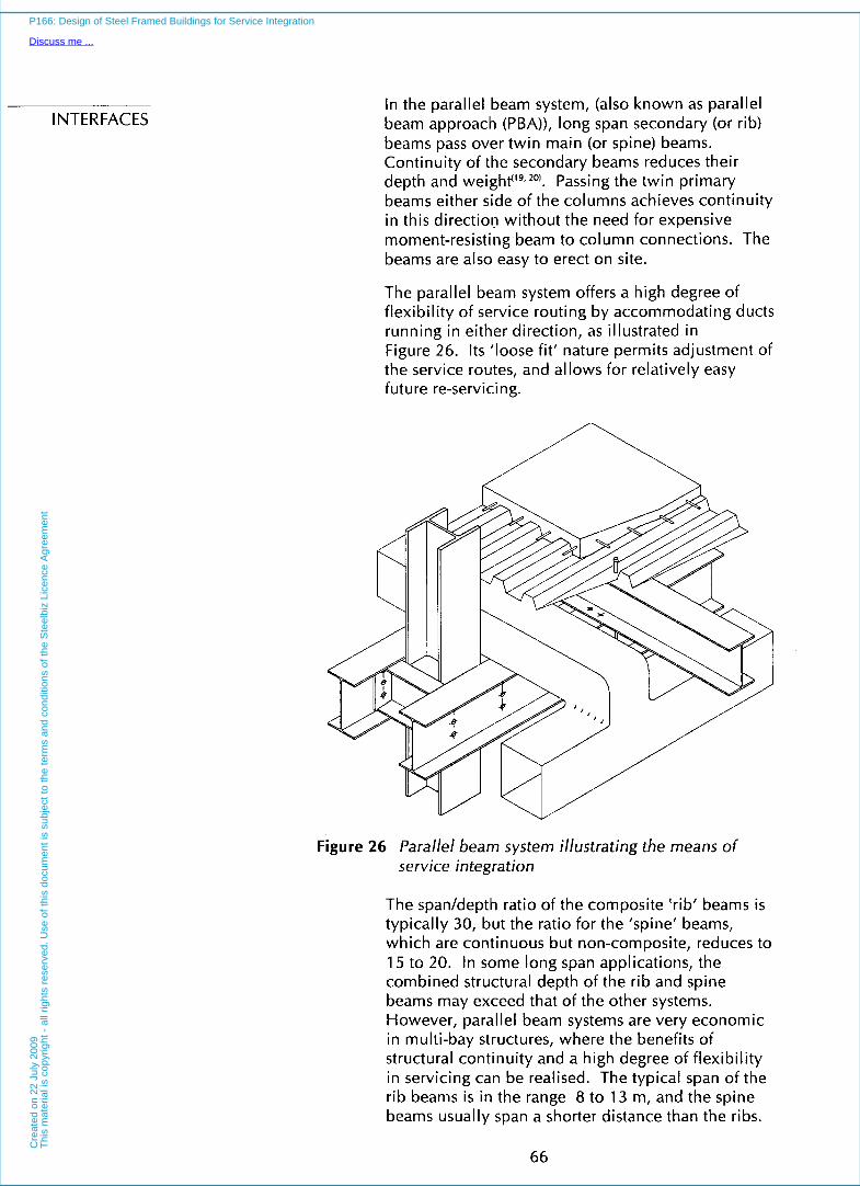
INTERFACES In the parallel beam system, (also known as parallel beam approach (PBA)), long span secondary (or rib) beams pass over twin main (or spine) beams. Continuity of the secondary beams reduces their depth and eight''^,^^). Passing the twin primary beams either side of the columns achieves continuity in this direction without the need for expensive moment-resisting beam to column connections. The beams are also easy to erect on site.
The parallel beam system offers a high degree of flexibility of service routing by accommodating ducts running in either direction, as illustrated in Figure 26. Its ’loose fit’ nature permits adjustment of the service routes, and allows for relatively easy future re-servicing.
Figure 26 Parallel beam system illustrating the means of service integration
The span/depth ratio of the composite ‘rib’ beams is typically 30, but the ratio for the ‘spine’ beams, which are continuous but non-composite, reduces to 15 to 20. In some long span applications, the combined structural depth of the rib and spine beams may exceed that of the other systems. However, parallel beam systems are very economic in multi-bay structures, where the benefits of structural continuity and a high degree of flexibility in servicing can be realised. The typical span of the rib beams is in the range 8 to 13 m, and the spine beams usually span a shorter distance than the ribs.
66
P166: Design of Steel Framed Buildings for Service Integration
Discuss me ...C
reat
ed o
n 22
Jul
y 20
09T
his
mat
eria
l is
copy
right
- a
ll rig
hts
rese
rved
. Use
of t
his
docu
men
t is
subj
ect t
o th
e te
rms
and
cond
ition
s of
the
Ste
elbi
z Li
cenc
e A
gree
men
t

The later assessments use 7.5 m span rib beams in order to achieve continuity in a 15 m wide building.
6.1 2 Summary of Service Zones Provided by the Various Structural Systems
Each structural option outlined above can accommodate openings for services but to varying degrees. Some are particularly well adapted to the provision of a large number of small openings, whereas others provide a small number of larger openings in certain prescribed locations. In the selection of a particular structural system, it is therefore necessary to consider the requirements of the services system. As a broad guide, Table 8 presents typical opening sizes for the range of structural system types covered in Sections 6.6 to 6.12. The table is based on the guidelines presented earlier for efficient structural design. Larger openings may be possible, if the structure is over- designed.
6.1 3 Vertical Cores
Vertical cores provide vertical zones for stairs, lift shafts, service ducts, toilet accommodation etc. They usually act as a key structural element offering lateral stability to the main structural frame. Reinforced concrete cores are widely used, but can be slower to construct, and openings for doorways and service penetrations must be carefully pre-determined, as later alterations may be expensive and difficult. The number and size of the openings may be limited by structural requirements.
Alternatively, vertical steel bracing in steel frames is easier and quicker to erect, and is lightweight. Bracing may be in ‘X’ or ‘K’ form and may use angle, tube or 1 sections depending on the horizontal forces to be resisted. X bracing in the form of cross-flats may be used, particularly in cavity wall applications. Dimensionally exact zones for services and door openings are not required until the later stages of design, and the location of the bracing members should permit some flexibility in planning.
Steel plate cores may be used in tall buildings where more stiffness is required than with bracing. The stiffened plates are more similar to bridge construction than to buildings, and are more efficient when designed for heavy shear loads.
67
P166: Design of Steel Framed Buildings for Service Integration
Discuss me ...C
reat
ed o
n 22
Jul
y 20
09T
his
mat
eria
l is
copy
right
- a
ll rig
hts
rese
rved
. U
se o
f th
is d
ocum
ent
is s
ubje
ct t
o th
e te
rms
and
cond
ition
s of
the
Ste
elbi
z Li
cenc
e A
gree
men
t

INTERFACES Plated steel cores can be built simultaneously with the main frame, whereas concrete cores must generally be built in advance. It is not unusual for a building to have more than one type of core depending upon the structural requirements and relative positions of the cores on plan.
Table 8 Summary of typical gross opening sizes for efficiently designed long span composite beams incorporating service zones
Spanldepth Opening Size for Beam Span of: Structural Option of Primary Beam’
12 m 15 m
Composite beam with 25 2 Q 300 x 600 1 Q 400 x 1000 stiffened openings in + 2 Q 350 x 700 low shear regions 20 2 Q 400 x 800 1 Q 500 x 1200
+ 2 Q 450 x 900
Composite beam with 25 2 Q 250 x 450 4 @ 300 x 600 stiffened openings in high shear region 20 2 Q 300 x 500 4 Q 375 x 750
Composite beam with 25 2 Q 250 x 450 2 @ 300 x 600 notches at ends of beam
20 2 Q 300 .x 600 2 Q 375 x 600
Castellated Beam’ 20 20 Q 240 20 Q 300 diameter diameter
Cellular Beam 20 20 Q 350 diameter
22 Q 400 diameter
Haunched Beam 30 250 x 9000 300 x 12000
Tapered Beam 20 2 Q 200 to 400 2 Q 250 to 500 x 3000 x 3000
Composite Truss 17 for 12 m span 4 Q 400 diameter 4 Q 400 diameter or 20 for 15 m span + 6 Q 250 diameter + 6 Q 250 diameter
+ 1 Q450 x 1000
Stub Girder 20 4 Q 300 x 900 2 Q400 x 1000 + + 4 Q 300 x 600 4 @ 400 x 700
4 Q 400 x 500
Parallel Beam 30 - secondary 400 deep 400 deep3 System 15 - primary continuous continuous
Assumptions: Ceiling - floor zone = 1250 mm Structural zone (beams and slab) = 900 mm Beam spacing = 6 m 1 Depth is steel section depth. Slab depth (about 130 mm) to be added
Structural zone deeper than 900 mm ’ May be restricted to applications as long span secondary beams
68
P166: Design of Steel Framed Buildings for Service Integration
Discuss me ...C
reat
ed o
n 22
Jul
y 20
09T
his
mat
eria
l is
copy
right
- a
ll rig
hts
rese
rved
. Use
of t
his
docu
men
t is
subj
ect t
o th
e te
rms
and
cond
ition
s of
the
Ste
elbi
z Li
cenc
e A
gree
men
t

7 CASE STUDY: COMPARISON OF STRUCTURAL OPTIONS
7.1 Typical Steel Framed Building
Steel framed buildings require a design approach which encompasses not only the structure but also the services, cladding and finishes. The design process should involve continual liaison and close co-ordination between architect, structural engineer and services engineer. The structural grid selected must be compatible with other grids, such as services layouts for air handling, power, lighting etc.
By way of a Case Study, a hypothetical but representative building is considered in this Section
69
P166: Design of Steel Framed Buildings for Service Integration
Discuss me ...C
reat
ed o
n 22
Jul
y 20
09T
his
mat
eria
l is
copy
right
- a
ll rig
hts
rese
rved
. Use
of t
his
docu
men
t is
subj
ect t
o th
e te
rms
and
cond
ition
s of
the
Ste
elbi
z Li
cenc
e A
gree
men
t

INTERFACES in order to draw out the important structure-service interactions for a range of structural systems that may be employed. The building is illustrated in Figures 27 and 28.
a*U
Figure 27 Illustration of the typical office building used in this study
The building in this Case Study has the following features:
Single 15 m beam span between facades. The floor space can be divided by a central column to give spans comparable short span systems.
Columns are spaced at 6 m centres along the facade.
Length of 60 m long with a central core and vertical service zone, and two smaller stairways
70
P166: Design of Steel Framed Buildings for Service Integration
Discuss me ...C
reat
ed o
n 22
Jul
y 20
09T
his
mat
eria
l is
copy
right
- a
ll rig
hts
rese
rved
. Use
of t
his
docu
men
t is
subj
ect t
o th
e te
rms
and
cond
ition
s of
the
Ste
elbi
z Li
cenc
e A
gree
men
t

with vertical service zones at each end of the building.
Height of 6 storeys, with a central plant room on the roof.
A floor-floor depth of 4.25 m, and a floor-ceiling depth of 3 m. A 150 mm deep raised access floor is also provided. In some cases, a slightly deeper floor-floor depth is required (and this depth is noted in reviewing the particular structural system).
A typical cross-section through the floor zone is shown in Figure 29.
i - 130
Figure 29 Vertical section through a typical floor
In order to determine the member sizes, the floor loading was assumed to be 5 kN/m2 (imposed load and partitions) and 1 kN/m2 (finishes), which i s typical for modern commercial buildings. The primary beams are designed to span the longer distance, and the secondary beams span 6 m.
This Case Study building may be considered representative for other configurations, for example the atrium-shape building shown in Figure 30. In this building, the linear form is repeated around the atrium (refer later to Figure B 1 0 in Appendix B).
71
P166: Design of Steel Framed Buildings for Service Integration
Discuss me ...C
reat
ed o
n 22
Jul
y 20
09T
his
mat
eria
l is
copy
right
- a
ll rig
hts
rese
rved
. Use
of t
his
docu
men
t is
subj
ect t
o th
e te
rms
and
cond
ition
s of
the
Ste
elbi
z Li
cenc
e A
gree
men
t
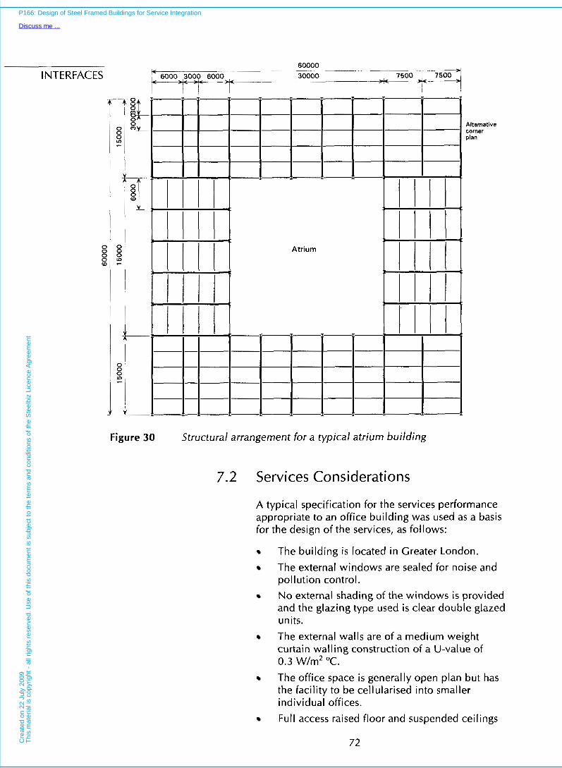
INTERFACES
x-
> > 3
Alternative corner plan
Atrium
Figure 30 Structural arrangement for a typical atrium building
7.2 Services Considerations
A typical specification for the services performance appropriate to an office building was used as a basis for the design of the services, as follows:
The building is located in Greater London.
The external windows are sealed for noise and pollution control. No external shading of the windows is provided and the glazing type used is clear double glazed units. The external walls are of a medium weight curtain walling construction of a U-value of 0.3 W/m2 "C. The office space is generally open plan but has the facility to be cellularised into smaller individual offices. Full access raised floor and suspended ceilings
72
P166: Design of Steel Framed Buildings for Service Integration
Discuss me ...C
reat
ed o
n 22
Jul
y 20
09T
his
mat
eria
l is
copy
right
- a
ll rig
hts
rese
rved
. Use
of t
his
docu
men
t is
subj
ect t
o th
e te
rms
and
cond
ition
s of
the
Ste
elbi
z Li
cenc
e A
gree
men
t

are to be installed. The depth of the raised floor is 150 mm for power, telecommunication and computer cable trays. The ceiling grid is 1500 mm square to match the planning grid and to relate to the structural module. The floor to ceiling height is 3 m.
Windows occur all around the building perimeter. The height is 1500 mm and the window sill level is 1000 mm above the raised floor level.
The major services plant is located at roof.
The building operating times are 8.00am to 6.00pm. The office population density is 1 person for every 1 o m2 of floor area.
The building design temperatures are:
Internal External
Winter 20°C -3°C dry bulb -3°C wet bulb
Summer 20°C 28°C dry bulb 20°C wet bulb
The acoustic criteria for the office space is NR 40.
The building internal heat gains are:
Specification Specification for in this study: Urban Offices:
Lights 1 5 W/m2 12 W/m2 Equipment 45 Wfm2 15 to 25 Wfm2 People 10 W/m2 10 WJm2
Total internal heat gains: 70 W/m2 4 7 W/m2
___
Recent research indicates that it is possible to reduce internal heat gains by 30 to 45%. However, the specification of 70 W/& i s typical of many modern offices and is used in this study. Lower heat gains may well lead to more effective use of chilled ceilingdbeams, and mixed-mode ventilation systems.
Only comfort cooling is provided to the occupied space. Since people can tolerate changes in relative humidity between 20 and 60% without great discomfort, the provision of a humidifier in the system is omitted in most commercial office applications. Hence, year
73
P166: Design of Steel Framed Buildings for Service Integration
Discuss me ...C
reat
ed o
n 22
Jul
y 20
09T
his
mat
eria
l is
copy
right
- a
ll rig
hts
rese
rved
. Use
of t
his
docu
men
t is
subj
ect t
o th
e te
rms
and
cond
ition
s of
the
Ste
elbi
z Li
cenc
e A
gree
men
t

INTERFACES
7.3
round temperature control without humidity control is provided. The implication of adopting a full air-conditioning system is to introduce further plant equipment, requiring larger plant rooms and further space within the overall building volume for ducts and/or pipework.
The building is designed with a sprinkler fire protection. An automatic fire detection system is also installed throughout the building.
Lifts are required for passenger transport and for fire fighting.
Fire "means of escape" assumptions:
(a) In assessing the population density per unit floor area, it is assumed that the nett floor area is 80% of the gross area, with the remaining 20% for lift/stairs/ toilets/plant.
(b) Buildings of three storeys or more require at least two means of escape for fire evacuation.
(c) The numbers of stairs required for means of escape is based on a direct distance to any protected stairway not exceeding 30 m radius. A total travel distance of 45 m is allowed once the internal layout is known.
(d) A fire fighting lift is required in all the examples. Each lift requires a plan area of approximately 2.5 m x 2.2 m. Fire fighting shafts are required for each 900 r d of floor area. Stairs in fire fighting shafts should be a minimum of 1100 mm width. Staircases may be pressurized, but this requires an additional vertical riser to provide this pressurisation.
Structural Considerations
The structural framing configuration comprises primary beams spanning 15 m spaced at 6 m centres, and supporting secondary beams at 3 m centres. A composite slab with lightweight concrete acting compositely with the primary and secondary members is adopted in all the composite beam designs. Structural designs have been made for the long span structural systems described in Section 6. These designs follow the principles of Eurocode 4(*), and are based on published design m e t h ~ d s " ~
All designs are based on the use of S355 steel and C25/30 concrete. Welded shear connectors are used
74
P166: Design of Steel Framed Buildings for Service Integration
Discuss me ...C
reat
ed o
n 22
Jul
y 20
09T
his
mat
eria
l is
copy
right
- a
ll rig
hts
rese
rved
. Use
of t
his
docu
men
t is
subj
ect t
o th
e te
rms
and
cond
ition
s of
the
Ste
elbi
z Li
cenc
e A
gree
men
t
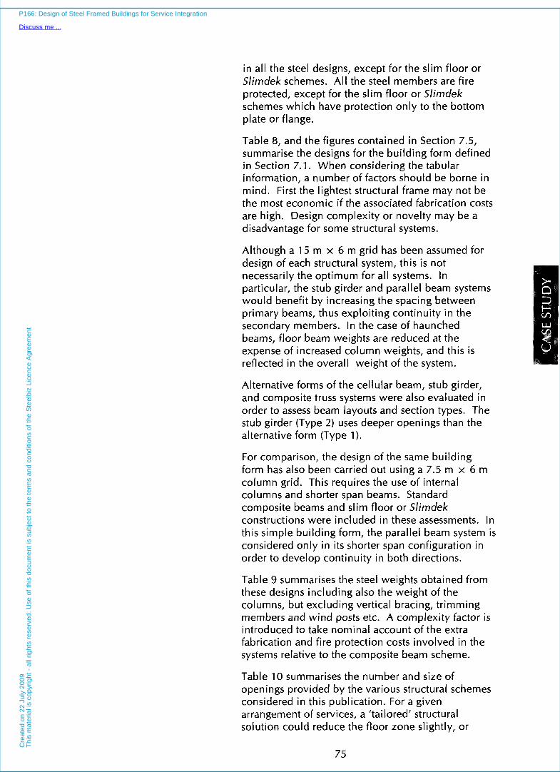
in all the steel designs, except for the slim floor or Slimdek schemes. All the steel members are fire protected, except for the slim floor or Slimdek schemes which have protection only to the bottom plate or flange.
Table 8, and the figures contained in Section 7.5, summarise the designs for the building form defined in Section 7.1. When considering the tabular information, a number of factors should be borne in mind. First the lightest structural frame may not be the most economic if the associated fabrication costs are high. Design complexity or novelty may be a disadvantage for some structural systems.
Although a 15 m x 6 m grid has been assumed for design of each structural system, this is not necessarily the optimum for all systems. In particular, the stub girder and parallel beam systems would benefit by increasing the spacing between primary beams, thus exploiting continuity in the secondary members. In the case of haunched beams, floor beam weights are reduced at the expense of increased column weights, and this is reflected in the overall weight of the system.
Alternative forms of the cellular beam, stub girder, and composite truss systems were also evaluated in order to assess beam layouts and section types. The stub girder (Type 2) uses deeper openings than the alternative form (Type 1).
For comparison, the design of the same building form has also been carried out using a 7.5 m x 6 m column grid. This requires the use of internal columns and shorter span beams. Standard composite beams and slim floor or Slimdek constructions were included in these assessments. In this simple building form, the parallel beam system is considered only in its shorter span configuration in order to develop continuity in both directions.
Table 9 summarises the steel weights obtained from these designs including also the weight of the columns, but excluding vertical bracing, trimming members and wind posts etc. A complexity factor is introduced to take nominal account of the extra fabrication and fire protection costs involved in the systems relative to the composite beam scheme.
Table 10 summarises the number and size of openings provided by the various structural schemes considered in this publication. For a given arrangement of services, a 'tailored' structural solution could reduce the floor zone slightly, or
75
P166: Design of Steel Framed Buildings for Service Integration
Discuss me ...C
reat
ed o
n 22
Jul
y 20
09T
his
mat
eria
l is
copy
right
- a
ll rig
hts
rese
rved
. Use
of t
his
docu
men
t is
subj
ect t
o th
e te
rms
and
cond
ition
s of
the
Ste
elbi
z Li
cenc
e A
gree
men
t

INTERFACES permit improvements in structural efficiency. However, this would be at the expense of flexibility of service routing and requirement for future re- servicing. The opening sizes stated are gross sizes. The available space for services may be reduced by fire protection to the structural members, and the insulation around the service ducts.
Table 9 Summary of steel weights for the long span and medium span structural systems
Weight of steel (expressed as kglm' floor area)
Structural System Primary Including Total, Including Beams Secondary including Complexity
Beams Columns Factor'
15 m span beams
Beam with Web Openings
Cellular Beam as Primary Beam
Cellular Beam as Secondary Beam
Haunched Beam
Tapered Beam
Composite Truss (SHSl2
Composite Truss (T and L)2
Stub Girder (Type 1 )
Stub Girder (TvDe 2)
26 23
9
16
22
23
26
23
30
36
33
33
26
32
33
36
37
40
47
44
4 4
44
43
44
47
48
51
49 46
46
48 46
48
52
51
54
7.5 m span beams
Parallel Beam System 13 24 37 39
Composite Beam 9 22 35 35
Slim Floor with Deep Deck3 23 28 41 43
Slimdek3 22 27 40 40
Note: 1 . The complexity factor is a multiple on the weight of the beams reflecting the increased fabrication and fire protection cost in some forms of construction.
2. Alternative truss configurations using hollow sections (SHS) or T and L members.
3. Reduced costs of fire protection in the slim floor and Slimdek schemes are considered later.
76
P166: Design of Steel Framed Buildings for Service Integration
Discuss me ...C
reat
ed o
n 22
Jul
y 20
09T
his
mat
eria
l is
copy
right
- a
ll rig
hts
rese
rved
. Use
of t
his
docu
men
t is
subj
ect t
o th
e te
rms
and
cond
ition
s of
the
Ste
elbi
z Li
cenc
e A
gree
men
t

Table 10 Summary of gross opening sizes for long span structural systems considered in this study
Structural Option Floor Beam Size Gross Opening Size Depth (15 m span) x Width Opening (mm) Area t
Composite Beam with 1200 686 x 254116 152 3 Q450 x 1100 11 Stiffened Openings or
686 x 254 U B 170 3 G3485 x 1000
Cellular Beam as 1300 835 x 229 cut from 550 dia Q 750 ctrs 30 Primary Beam 610 x 229UB 140 ( = 18 openings)
Cellular Beam as 11 50 457 x 152 x 30T 400 dia Q 600 ctrs 23 Secondary Beam + 533 x 210 x 41T ( = 23 openings)
Haunched Beam 1250 457 x 191UB 82 1 Q 310 x 12500 29 _._______ ~-
Tapered Beam 1300 750 deep max. 2 Q 450 to 200 x 23 5000
Truss - Type 1 (SHS) 1350 870 overall depth 1 550 x 1500 17
Truss -Type 2 (T and L) 1350 870 overall depth + 2oo x loo0 or 15 + 8 Q 300 dia
or 4 Q 400 dia
Stub Girder - Type 1 1200 305 x 305 UC 1 1 8 10 Q 400 x 750 22 plus406 x 140UB39 stubs
Stub Girder - Type 2 1350 254 x 254UC89 1 Q 600 x 1200 31 (deeper openings) plus 610 x 2 Q 600 x 1000
229UB101 stubs 2 @ 600 x 750
Parallel Beam System 1 100 305 x 165UB46 2 Q 300 x 7200 32 (7.5 m span) + 254 x 146UB31 cross-over to
250 x 5700
Composite Beam 1200 406 x 178UB54 2 x 310 x 7200 35 (7.5 m span)
Slim Floor/S/imdek 1000 254 x 254UC89 2 x 350 x 7200 52 (7.5 m span) + 450 x 15 plate
or 280 AS6 136
t expressed as percentage of beam span x floor to ceiling zone (less raised floor and lighting)
7.4 Structural Beam Details and Building Framing Plans
The elevations of the various beam designs considered in this report are shown in Figures 31 to 38, together with the framing plans for the building shape considered. For comparison, alternative 7.5 m span designs are presented in Figures 39 and 40. The 7.5 m span composite beam scheme is not illustrated, as it is conventional technology.
The elevations show the dimensions for the beams based on the design criteria stated earlier. Some of the beams could have been shallower, but the need
77
P166: Design of Steel Framed Buildings for Service Integration
Discuss me ...C
reat
ed o
n 22
Jul
y 20
09T
his
mat
eria
l is
copy
right
- a
ll rig
hts
rese
rved
. Use
of t
his
docu
men
t is
subj
ect t
o th
e te
rms
and
cond
ition
s of
the
Ste
elbi
z Li
cenc
e A
gree
men
t

INTERFACES to provide sensible openings for services has led to the dimensions as shown. The figures show the details of the form of construction for each structural system. Also given is the equivalent weight of each primary beam and the weight of each secondary beam expressed in kg of steel per m2 plan area. Heavier edge beams may be required to support the cladding. Shear connectors are not shown in Figures 31 to 38, but are required in all the composite schemes.
254x1 02x25 UB
Notes: 485 deep, openinqs : 6 8 6 x 2 5 4 ~ 1 7 0 UB, + stiffeners Beam welght = 650 kg = 29.4 kglm
450 deep, openin S . 6 8 6 x 2 5 4 ~ 1 5 2 UB + stiffeners Beam welght = 9 3 8 0 k 8 = 26.4kg/m2 Secondary beams = IO. kg/mz
Figure 31 Structural design of composite beam with web openings
r- 2 5 4 ~ 1 0 2 ~ 3 1 UB /- 2 5 4 x 1 0 2 ~ 2 5 UB /- 130 composite slab
l-- l l l C I1 ! l !
\i-500mm diameter holes ' L C e l l u l a r beam fabricated from at 750mm centres 61 0x229~140 UB
Beam weight = 2100 kg =23.3 kg/m2 Secondary beams = 10.8 kg/m2
Figure 32 Structural design of cellular beam as primary beam
78
P166: Design of Steel Framed Buildings for Service Integration
Discuss me ...C
reat
ed o
n 22
Jul
y 20
09T
his
mat
eria
l is
copy
right
- a
ll rig
hts
rese
rved
. Use
of t
his
docu
men
t is
subj
ect t
o th
e te
rms
and
cond
ition
s of
the
Ste
elbi
z Li
cenc
e A
gree
men
t

, 130 composite slab
Lo (D (D
4 5 7 x 1 9 1 ~ 6 7 U
-4
7 457x1 52x60 UB 'T' Section through beam I 5 3 3 x 2 1 0 ~ 8 2 UB 'T'
Weight = 2x1 070 kg per 6m along Beams at 3 m spacing
the building = 23.7 kglml
Edge beams = 8.9 kglm'
Figure 33 Alternative structural design of cellular beam as secondary beam
3 m
254x102~25 UB 130 composite slab
3000 & 3000 & 3000
7= ImL1 r 1 1
457x191~82 UB
Haunch cut from 457x191~82 UB
15000 I - ---A r
Additional weight of column not included
T I
Secondary beams = 10 kglm' Beam weight = 1450 kg = 16.1 kg/mz
Figure 34 Structural design of haunched composite beams
/ 2 5 4 x 1 0 2 ~ 3 1 UB 2 5 4 x 1 0 2 ~ 2 5 UB / / 130 composite slab
3000 \J 3000 3000 .L 3000 <
4-4 t 7
7. >< F.
1500 4 - h r l l
k In PI
PI
m -L - Tapered beam (fabricated from plate) ----$-- Flanges - 250 wide x 25 thick Web - 9 mm thick
L- 15000 - _ _ ~ _ _ _ . _ _ 4 Weight = 2015 kg =22.3 kglm2 Secondary beams = 10 kg/mz
Figure 35 Structural design of tapered beam
79
P166: Design of Steel Framed Buildings for Service Integration
Discuss me ...C
reat
ed o
n 22
Jul
y 20
09T
his
mat
eria
l is
copy
right
- a
ll rig
hts
rese
rved
. Use
of t
his
docu
men
t is
subj
ect t
o th
e te
rms
and
cond
ition
s of
the
Ste
elbi
z Li
cenc
e A
gree
men
t

254x102~25 UB 130 composite slab 150x1 50x8 SHS top chord
~ 3000 =i: ,/3000 ~ - / 3000 ~ ~~ 3000/=+ 3000 ~
I
~ _ _ _ 1,400 dia. rnax
INTERFACES
300 dia. m a d / ' 1000x200 max \l 50x1 50x16 SHS bottom 'chord
100x1 00x6.3 SHS / Vierendeel / 11 20x1 20x8 SHS (Typical verticals) 1500~570(approx.) (Typical diagonals) l
l I 15000 1 - , Alternative T and Angle sections: Truss weight S.H.S. sections = 2100 kg = 23.3 kglrn' Top chord = 305x1 52x49 kg/m T Secondary beams = 10 kglm' Bottom Chord = 305x1 52x69 kg/m T
Truss weight = 2325 kg = 25.8 kglm' Diagonals = 2 No 120x1 20x1 2kglm Angle
Figure 36 Structural design of composite truss using hollow sections
Requires propping during construction Beam weight = 2060 kg = 22.9 kglm' Secondary beams = 13.7 kglm'
Figure 37 Structural design of stub girder (Type 7)
122x1 52x24 T 254x1 02x25 UB 0x229~101 UB stubs
- _ _ _ - . _ ~ ~ ~ _ . _ _ _ _ _ _ _ . ~ 15000 4
Beam weight = 2700 kg = 30 kglm' Secondary beams = 10 kg/m*
Figure 38 Structural design of stub girder (Type 2)
80
P166: Design of Steel Framed Buildings for Service Integration
Discuss me ...C
reat
ed o
n 22
Jul
y 20
09T
his
mat
eria
l is
copy
right
- a
ll rig
hts
rese
rved
. Use
of t
his
docu
men
t is
subj
ect t
o th
e te
rms
and
cond
ition
s of
the
Ste
elbi
z Li
cenc
e A
gree
men
t
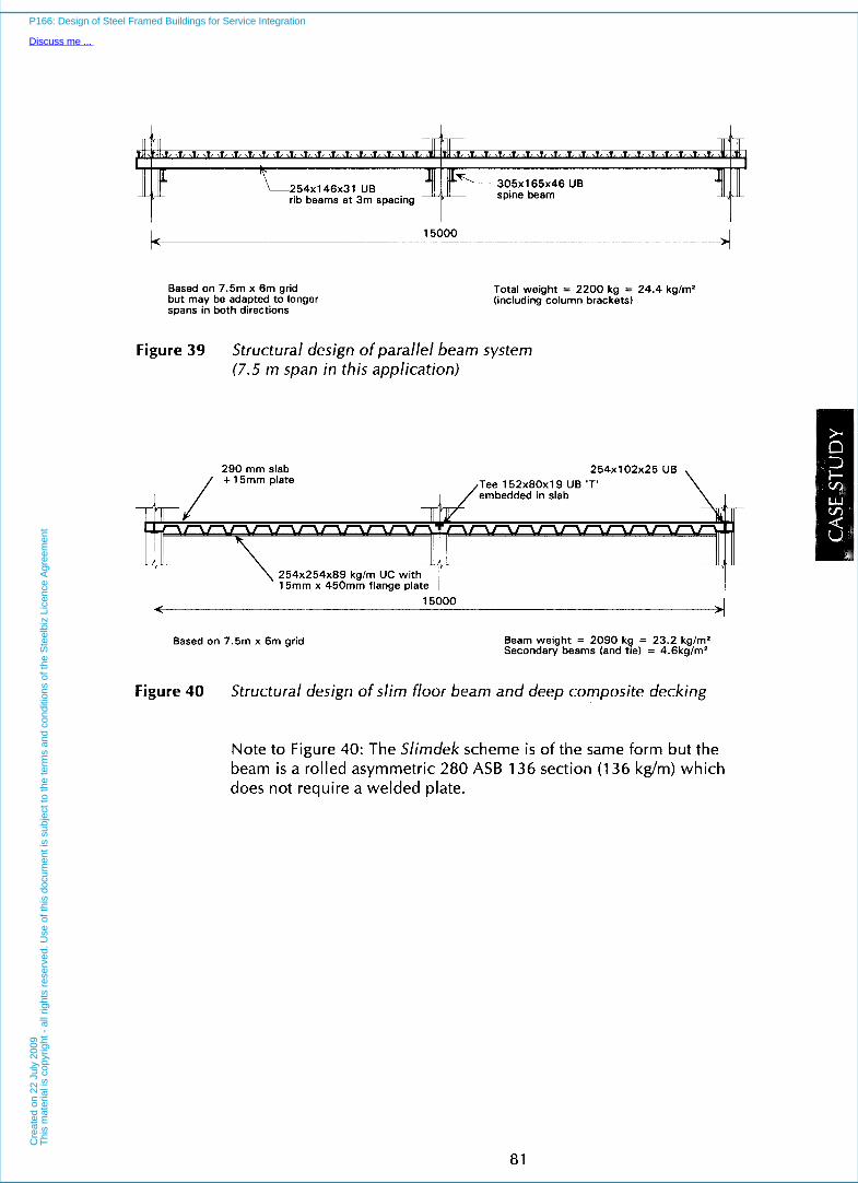
I I
254x146~31 UB 1 ip'- 305x1 65x46 UB rib beams at 3m spacing ''r spine beam
' 15000 4 Based on 7.5117 x 6m grid
wans in both directions but may be adapted to longer
Total weight = 2200 kg = 24.4 kglm' (including column brackets)
Figure 39 Structural design of parallel beam system (7.5 m span in this application)
290 mm slab 254x102~25 UB Tee 152x80~19 UB 'T' embedded in slab
254x254~89 kglm UC wit 15mm x 450mm flange plate
L 15000 . 1 -
Based on 7.5m x 6m grid Beam weight = 2090 kg = 23.2 kglm' Secondary beams (and tie) = 4.6kg/mz
Figure 40 Structural design of slim floor beam and deep composite decking
Note to Figure 40: The Slimdek scheme is of the same form but the beam is a rolled asymmetric 280 ASB 136 section (1 36 kg/m) which does not require a welded plate.
81
P166: Design of Steel Framed Buildings for Service Integration
Discuss me ...C
reat
ed o
n 22
Jul
y 20
09T
his
mat
eria
l is
copy
right
- a
ll rig
hts
rese
rved
. Use
of t
his
docu
men
t is
subj
ect t
o th
e te
rms
and
cond
ition
s of
the
Ste
elbi
z Li
cenc
e A
gree
men
t

INTERFACES
a2
P166: Design of Steel Framed Buildings for Service Integration
Discuss me ...C
reat
ed o
n 22
Jul
y 20
09T
his
mat
eria
l is
copy
right
- a
ll rig
hts
rese
rved
. Use
of t
his
docu
men
t is
subj
ect t
o th
e te
rms
and
cond
ition
s of
the
Ste
elbi
z Li
cenc
e A
gree
men
t

8 CASE STUDY: SERVICE DISTRIBUTION
This Section reviews the service distribution for the various structural systems described in Section 6, for the building form in the Case Study described in Section 7.
To meet building and fire regulations, a building of this shape would require three vertical service zones. It is considered that escape stairways would be placed at each end of the building, and that a core area for lifts and toilets would be provided in the centre. Thus, these vertical riser positions dictate where the vertical services distribution can be economically located.
Natural cross-flow ventilation in a long thin building is feasible, but it imposes limitations on the use of
83
P166: Design of Steel Framed Buildings for Service Integration
Discuss me ...C
reat
ed o
n 22
Jul
y 20
09T
his
mat
eria
l is
copy
right
- a
ll rig
hts
rese
rved
. Use
of t
his
docu
men
t is
subj
ect t
o th
e te
rms
and
cond
ition
s of
the
Ste
elbi
z Li
cenc
e A
gree
men
t

INTERFACES internal partitions. Internal offices, for example, would require mechanical ventilation. It has therefore been assumed that the windows are sealed and mechanical ventilation is provided throughout the whole floor area. Good daylight penetration is achieved with this building shape leaving only a central 7 m wide strip cequiring permanent artificial lighting. The simple shape of the building allows maximum use of linear air diffusers along the perimeter of the building.
It is considered that the major vertical services would be located in the central core in order to facilitate the use of a single plant room. Therefore, both outlet and inlet ducts or pipes would emanate from this area and would have to be designed to pass through or under the long span beam systems.
This simple building shape would be ideally suited to any of the structural forms used for long span buildings. A complete range of long span structural and service designs has therefore been studied for this building and the solutions are presented in Figures B1 to B 7 (Appendix B). Application of the scheme in Figure B1 to an alternative building form is shown in Figure B10.
The Variable Air Volume (VAV) air-conditioning system reviewed in Section 4.3 occupies the greater volume within the floor-ceiling zone and therefore is more problematical in terms of the structure-service integration. Nevertheless, the Fan Coil system is also considered, for comparison, in one case (see Figure 82). Additionally, the service distribution for the short (7.5 m) span composite beam, and slim floor systems are also considered in Figures B8 and B9.
The service arrangements are shown in the following sequence in Appendix B. All are Variable Air Volume (VAV) systems, except where noted. These figures are:
B1 Uniform depth composite beam with web openings
B2 Uniform depth composite beam with web openings - Fan Coi I system
B3 Cellular beam as primary beam B4 Haunched beam B5 Tapered beam B6 Composite truss using SHS B7 Stub girder (Type 2) B8 Composite beam (7.5 m x 6 m grid) B9 Slim floor with deep composite decking B10 Application to alternative building form
84
P166: Design of Steel Framed Buildings for Service Integration
Discuss me ...C
reat
ed o
n 22
Jul
y 20
09T
his
mat
eria
l is
copy
right
- a
ll rig
hts
rese
rved
. Use
of t
his
docu
men
t is
subj
ect t
o th
e te
rms
and
cond
ition
s of
the
Ste
elbi
z Li
cenc
e A
gree
men
t

9 CASE STUDY: COST IMPLICATIONS OF STRUCTURAL SYSTEMS
9.1 General Aspects
The choice of structural system is obviously influenced by the cost of materials and construction. Any broad economic assessment should take into account the whole cost of the building which-should include the:
Structure and floors
Cladding
85
P166: Design of Steel Framed Buildings for Service Integration
Discuss me ...C
reat
ed o
n 22
Jul
y 20
09T
his
mat
eria
l is
copy
right
- a
ll rig
hts
rese
rved
. Use
of t
his
docu
men
t is
subj
ect t
o th
e te
rms
and
cond
ition
s of
the
Ste
elbi
z Li
cenc
e A
gree
men
t
Services distribution Foundations
Finishes Speed of construction
Other aspects such as increased lettable area, and flexibility in use of internal column-free space represent value to the client, but are not considered in this Study.
INTERFACES
Clearly, the absolute level of costs of construction is strongly influenced by global and local economic factors. Since early 1990, prices for all construction materials have fallen significantly reaching a low point at late 1992 and then rising gradually since then. Therefore, it is important to address the cost differences in relative, rather than absolute terms in order to provide generic guidance on the economy of different forms of construction.
The form of the building considered in this publication is also simplified. It may be expected that structure costs, in particular, are lower than those of recently constructed buildings which may have variations on shape and often have substantial basements, or temporary works during construction.
The following sections describe how the cost differences among the various structural systems have been determined. All the systems are assessed on the basis of prices of tendered projects in the UK (mid 1995).
Cost estimates have only been made for the building considered in this publication, but it may be expected that the general conclusions are relevant to the other building forms. The costs are comparable to those presented in SCI Publication 1 3Y2’).
9.2 Structure Cost
The structural costs of the various systems comprise common and variable items. For example, common to all long span steel systems i s the use of composite slabs. Variable items are the:
Weight of steel used
Complexity of the steel fabrication Fire protection costs
The basic cost of fabricated steel used in beams and columns is taken as f 850honne (l 190 ecushonne) for grade S 235 or S 275 steel, and €900/tonne
86
P166: Design of Steel Framed Buildings for Service Integration
Discuss me ...C
reat
ed o
n 22
Jul
y 20
09T
his
mat
eria
l is
copy
right
- a
ll rig
hts
rese
rved
. Use
of t
his
docu
men
t is
subj
ect t
o th
e te
rms
and
cond
ition
s of
the
Ste
elbi
z Li
cenc
e A
gree
men
t

(1260 ecus/tonne) for grade S 355 steel. This rate includes delivery and erection, but excludes corrosion or fire protection costs. These rates wil l increase with increasing irregularity of the structural form. In Table 9, the additional fabrication cost in some structural systems is reflected in a complexity factor applied to the basic weight of steel in each scheme.
The weight of the vertical bracing and other secondary steelwork is taken as equivalent to 4 kg/m2 floor area. This is costed at f5/m2 (7 ecus/m2) in all the steel schemes due to the greater fabrication effort required for the bracing elements. Shear connectors are placed at one every 150 mm along the primary beams, and are costed at f3/m2 (4 ecus/m2) floor area in all the composite schemes (excluding slim floor and Slimdek).
Similarly, fire protection costs may be evaluated by taking account of the size of the steel beam and column sections to be protected. In this case, fire protection is assumed to be vermiculite spray of a thickness (20 to 25 mm) suitable for 90 minutes fire protection. Typically, fire protection costs are approximately 20% of the cost of the fabricated steelwork, and are taken as a global figure of f9/m2 (1 3 ecus/m2) floor area for all the composite schemes, reducing to f4/m2 (6 ecus/m2) for the slim floor and Slimdek schemes. The complexity factor in Table 9 also takes into account the reduced or increased complexity of fire protection, as required for each system.
The cost of the composite slabs, lightweight concrete, steel decking and reinforcement is taken as a common figure of f25/m2 (35 ecus/m2) floor area for all the composite structural systems. For comparison, cost estimates are also made of slim floor and reinforced concrete designs based on a 7.5 m x 6 m grid. The longer spanning deep deck composite slab is costed at €38/m2 (53 ecus/m2). The reinforced concrete design is based on a 300 mm deep flat slab with 600 mm square internal columns. It is costed at f 80/d (1 12 ecus/m2), as obtained from typical cost data-bases in the UK22). A further f8/m2 (1 1 ecus/m2) is allowed for the shear walls and cores etc., in this concrete scheme.
Various other common structural items, such as cladding supports, plant room, roof, stairs, lift supports etc., are taken as f 2 4 / d (34 ecus/m2) for a / / schemes, as obtained from other studied2'). The total
87
P166: Design of Steel Framed Buildings for Service Integration
Discuss me ...C
reat
ed o
n 22
Jul
y 20
09T
his
mat
eria
l is
copy
righ
t -
all r
ight
s re
serv
ed.
Use
of
this
doc
umen
t is
sub
ject
to
the
term
s an
d co
nditi
ons
of t
he S
teel
biz
Lice
nce
Agr
eem
ent

INTERFACES
9.3
structural cost is therefore in the range of f98 to 11 5/m2 floor area.
Cladding Costs
Cladding costs are assumed to vary in proportion to building height, which is itself dependent on the depth of the floor zone. In these estimates it is assumed that the building is clad in brickwork with double glazed windows. The brickwork is assumed to have various complex features and is costed at a rate of f 200/m2 (280 ecus/m2) wal I area.
The cost of modern building facades may vary between f 100 and 500/m2, depending on the materials used and, therefore, the influence of cladding cost may be estimated proportionately. The variable cost of the cladding is due to the difference in the depth of the structural system, and hence floor zone, that is used. The cost of.the cladding is presented as relative to the floor area, which is therefore dependent on the shape of the building.
9.4 Services Distribution
A major study was carried out of the influence of the various structural options on the cost of service distribution, using the designcriteria given in Section 7.3. Both VAV and Fan Coil systems were costed.
The cost estimates included the following common and variable items in a typical air-conditioning system, as follows:
Common Items Central plant machinery and controls
Vertical ducts Outlet air diffusers
Variable Items Rectangular air ducts
Circular air ducts
VAV or Fan Coil Units
Perimeter heating
Volume control dampers
In both air-conditioning systems, VAV and Fan Coil, it is assumed that the VAV or Fan Coil Units are
80
P166: Design of Steel Framed Buildings for Service Integration
Discuss me ...C
reat
ed o
n 22
Jul
y 20
09T
his
mat
eria
l is
copy
right
- a
ll rig
hts
rese
rved
. Use
of t
his
docu
men
t is
subj
ect t
o th
e te
rms
and
cond
ition
s of
the
Ste
elbi
z Li
cenc
e A
gree
men
t

positioned one every 36 m2 floor area internally, and one every 27 m2 around the edges of the building.
The main cost differences arise from the method of air distribution, circular ducts being generally more efficient and cheaper than rectangular ducts. The length, and number of ducts is also influenced by the choice of structural system.
The costs of the VAV and Fan Coil systems for this Case Study building are presented in Table 1 1 . The cost differences are only significant for the VAV system and, therefore, this system is used as a basis for comparison among the structural systems. Fan Coil systems are slightly cheaper (by 2 to 5%) but are not so widely used for this type of building.
The total cost of the air-conditioning system for the building in this study is estimated as approximately f 1 78/m2 (249 ecus/m2) floor area, and comprises three main parts as follows:
Air ducting f 77/m2 (1 08 ecus/m2) Perimeter heating f 1 O/m2 (1 4 ecus/m2)
Central plant f 88/m2 (1 23 ecus/m2) (averaged over the total floor area)
These costs depend on the particular building configuration and services specification, and may vary significantly in other projects. However they have been used to illustrate the principal factors that influence the service costs in this Case Study.
Table 11 Costs of VAV and Fan Coil Systems for the Case Study building expressed as €/m2 floor area (E 7 = 1.40 ecus)
(a) Cost of VAV Air-conditioning System
Structural System Ductwork Insulation Volume VAV Perimeter Total
Circular Rectangular/ - to Ducts Control Boxes Heating Cost
Dampers ff m* ~.
Other
Beam with Web Openings 12.5 13.1 3.2 11.0 33.3 10.0
Cellular Beam 15.8 8.0 3.2 1 1 . 1 33.3 10.0
Haunched Beam Parallel Beam 1 11.2 14.5 2.8 11.0 33.3 10.0
Tapered Beam 12.8 17.6 3.5 10.8 33.3 10.0
Composite Truss 14.6 10.9 3.1 11.3 33.3 10.0
Stub Girder 12.6 13.5 3.1 11.0 33.3 10.0
Composite Beam (7.5 m span) 12.3 17.9 3.1 10.9 33.3 10.0
Additional cost of central plant apportioned over this floor area = f88/m2
83.1
81.4
82.8
88.0
83.2
83.5
87.5
89
P166: Design of Steel Framed Buildings for Service Integration
Discuss me ...C
reat
ed o
n 22
Jul
y 20
09T
his
mat
eria
l is
copy
right
- a
ll rig
hts
rese
rved
. Use
of t
his
docu
men
t is
subj
ect t
o th
e te
rms
and
cond
ition
s of
the
Ste
elbi
z Li
cenc
e A
gree
men
t

INTERFACES Table 11 continued
(b) Cost of Fan Coil Air-conditioning System
Structural System Ductwork Insulation Volume Fan Coil Pipe Total to Ducts Control Units Work Cost
Circular Rectangular/ Dampers Elm2 Other
Beam with Web Openings 14.1 10.9 9.5 4.1 25.5 36.9 101.0
Cellular Beam 17.4 8.3 9.3 4.3 25.5 36.9 101.7
Haunched Beam Parallel Beam l 13.3 12.3 9.6 4.1 25.5 36.9 101.7
Tapered Beam 15.4 11.0 9.7 4.5 25.5 36.9 103.0
Composite Truss 16.3 9.6 9.5 3.9 25.5 36.9 101.7
Stub Girder 17.0 8.4 9.6 4.8 25.5 36.9 102.2
Composite Beam (7.5 m span) 15.4 11.3 9.6 4.0 25.5 36.9 102.7
Additional cost of central plant apportioned over this floor area - f66/m2
Notes: Costs in Table 11 are appropriate to the UK in 1995.
The approximate variation in cost of the service distribution, as influenced by the choice of the structural system, may be summarised as in Table 12. These variations are.rounded in terms of percentages relative to the cost of services in a standard composite beam system.
In comparison, it may be assumed that systems offering a flat or ribbed floor, such as slim floors, provide complete flexibility of service distribution and, therefore, are similar in service cost to the best of the long span systems.
Table 12 Structural system Variation in Total Cost of
Variable cost of Services
service distribution due Percentage Elm2 ecus/m2 to structural system Cellular Beam
-3.5% -f 6 (8)
Parallel Beam System -2.5% -f 5 ( 7)
Haunched Beam -2.5 "lo -f 5 ( 7)
Stub Girder -2.0% -f 4 (5) Composite Truss -2.0% -f 4 (5)
Beam with Web Openings -2.0% -f 4 (5)
Tapered Beam 0 0 0
Beam with Services Below 0 0 0 These percentage variations are approximate and arranged in decreasing order of cost saving.
9.5 Foundation Costs
The foundation costs depend on the number and size of the foundations and, therefore, on the vertical load to be resisted. These costs are likely to be similar for all the long span structural systems examined in this study.
90
P166: Design of Steel Framed Buildings for Service Integration
Discuss me ...C
reat
ed o
n 22
Jul
y 20
09T
his
mat
eria
l is
copy
right
- a
ll rig
hts
rese
rved
. Use
of t
his
docu
men
t is
subj
ect t
o th
e te
rms
and
cond
ition
s of
the
Ste
elbi
z Li
cenc
e A
gree
men
t

In comparison, the systems based on a 7.5 m x 6 m grid require more foundations, although they are smaller in size. A parallel study by the SCP) has shown that the overall foundation costs of the long span systems are approximately 10% lower than those of the short span systems. In this Case Study, foundation costs are assumed to be approximately 3% of the total building cost, although these costs may increase considerably in inner city sites.
The concrete scheme is heavier than the steel schemes and, therefore, requires larger foundations. It may be assumed that foundation costs are in proportion to the total load to be supported.
9.6 Speed of Construction
All steel systems have the inherent benefit of speed of construction. The long span systems may be assumed to be of similar complexity and may be slightly faster to construct than the short span systems due to the smaller number of steel elements that have to be lifted into place. However, this benefit is neglected conservatively in this Case Study.
Comparisons of speed of construction of steel construction with equivalent reinforced concrete designs have concluded that overall time savings may be of the order of 6 weeks in a construction period of 70 weeks for a steel framed building of the size considered in this publication. Therefore, time-related savings may be estimated on the basis of:
Reduced site preliminaries (cost of site accommodation, equipment and site management).
for the building construction. Reduced financial cost of borrowing the capital
Early rental income.
Site preliminaries are conservatively based on 7.5% of the project value, although traditionally 12 to 20% has been the case on large projects. For an assumed total building cost of f 8 5 0 / d (1 190 ecus/m2), a reduction of one week in a construction period of 70 weeks corresponds to f0.9/m2 (1.3 ecus/m2) equivalent saving per unit floor area. Furthermore, the financial cost of borrowing to the client over the construction period may be estimated using a representative interest rate of 8% applied to the payments for the building averaged over the period,
91
P166: Design of Steel Framed Buildings for Service Integration
Discuss me ...C
reat
ed o
n 22
Jul
y 20
09T
his
mat
eria
l is
copy
right
- a
ll rig
hts
rese
rved
. Use
of t
his
docu
men
t is
subj
ect t
o th
e te
rms
and
cond
ition
s of
the
Ste
elbi
z Li
cenc
e A
gree
men
t

INTERFACES
9.7
which is equivalent to f0.7/rd (1 .O ecus/m2) for each week of the construction. The total potential saving is therefore at least f 1.6/rd (2.2 ecus/m2) per week saving in construction time.
Overal I Cost Estimates
The structure costs can be determined reasonably accurately using the information presented in Section 9.2. The results are presented in Table 13, expressed in terms of cost per square metre of gross floor area. Also shown for comparison are the best estimates of the cost of the slim floor (and Slirndek) and the reinforced concrete (RC) flat slab schemes. Alternative cellular beam, stub girder and composite truss schemes are included for the long span options.
Account is taken of the variable costs, as covered in Sections 9.2 to 9.6. The true comparison of the cost of the construction should, therefore, be the sum of the structure cost and these variable costs.
The standard 7.5 m span composite beam and slab system is used as the ‘base’ cost, and all the other systems considered in this study are expressed as ’plus’ or ’minus‘ relative to the base value. These results are consistent with a recent cost study carried out by SCI on behalf of British Steef2’).
For this Case Study, it is apparent that the variable costs can be as significant as the variations in structure cost among all the schemes, and that the potential savings in cladding and services cost are as important. If the service distribution had been more complex, then the variation in these costs would have been greater. The long span systems also offer greater flexibility in internal planning which could be taken into account in terms of the rental of the space.
It is concluded that the cellular beam system is the cheapest of all the long span systems and adds a negligible 0.1 to the overall cost of the bljilding, relative to the shorter span ‘base’ scheme. The typical average cost increase of all the long span systems is less than 2% relative to the ‘base’ scheme. The Slirndek and parallel beam systems are the cheapest overall, but are only considered as a 7.5 m x 6 m grid. The reinforced concrete scheme is the most expensive of all the shorter span systems, due largely to the implications of speed of construction.
92
P166: Design of Steel Framed Buildings for Service Integration
Discuss me ...C
reat
ed o
n 22
Jul
y 20
09T
his
mat
eria
l is
copy
right
- a
ll rig
hts
rese
rved
. Use
of t
his
docu
men
t is
subj
ect t
o th
e te
rms
and
cond
ition
s of
the
Ste
elbi
z Li
cenc
e A
gree
men
t

Table 13 Summary of total building costs (relative to the composite beam and slab scheme) in the Case Study
Element of Non-Integrated Services Parallel Composite Cellular Haunched Tapered Stub Composite Construction Composite Slim Floor and Reinforced
Integrated Services
Beam and Deep Deck or Concrete Flat Beam Beam with Beam Beam Beam Girder Truss Slab Slirndek Slab System Web Openings
Foundations 20 0 + 5 + 4 + l 3 + 10 + l 2 + 10 +14/+17 +12/+15 Structure, roof, stairs 98 +9 /+12 + l4
0 -1 -1 -1 -1 -1 -1
Mechanical Services 178 -6 -6 -3 0 -2/+ 3 + 2 + 3 0/+ 5 + 5 Cladding 140 -7 -7 -5 -4 -6 -5 - -41-6 -4
Other Common 350 approx - - - - - -
costs Site Preliminaries 64 0 + 5 0 0 0 0 0 0 0 TOTAL COST (flm' 850 -41-1 +l 1 -4 +8 +11+6 +8 +l2 +g/+ 15 + 12/+ 15 floor area) Financing Cost 46 - + 4 ~ - - - - VARIATION Base -0.41-0.1 '10 + 1.7% 1 -0.4% +0.9% +0.1/+0.7% + 0.9% + 1 .3% + 1 .O/+ 1.7% + 1.3/+ 1.7%
Note: Costs are given as +/- relative to the 'base' 7.5 m composite beam and slab scheme.
- - -
- - -
Alternative cellular beam, stub girder and truss schemes are costed. The costs in this table have been derived for the Case Study in this publication. Absolute costs may vary considerably for other building forms and specifications. However, the cost variations are typical of other SCI cost studies. The building cost increase in the UK from mid-l 995 to late 1997 i s approximately 8%
P166: Design of Steel Framed Buildings for Service Integration
Discuss me ...C
reat
ed o
n 22
Jul
y 20
09T
his
mat
eria
l is
copy
right
- a
ll rig
hts
rese
rved
. Use
of t
his
docu
men
t is
subj
ect t
o th
e te
rms
and
cond
ition
s of
the
Ste
elbi
z Li
cenc
e A
gree
men
t

INTERFACES
94
P166: Design of Steel Framed Buildings for Service Integration
Discuss me ...C
reat
ed o
n 22
Jul
y 20
09T
his
mat
eria
l is
copy
right
- a
ll rig
hts
rese
rved
. Use
of t
his
docu
men
t is
subj
ect t
o th
e te
rms
and
cond
ition
s of
the
Ste
elbi
z Li
cenc
e A
gree
men
t

10 CONCLUSIONS
The integration of building services in the floor-ceiling zone of modern commercial buildings is addressed by first considering the different types of air-conditioning and comfort cooling systems, and then reviewing the various structural systems that may be used. The use of steel and composite construction is often associated with longer spans in which greater flexibility of internal planning is provided. Many long span structural systems have been developed in recent years which provide for various degrees of service integration. Conversely, the slim floor and other forms of shallow floor construction have been developed to achieve a medium span solution in which services are mainly located beneath the floor.
This publication reviews the benefits of long span beams utilising the principles of composite construction, which offer the facility for integration of structure and services within the same horizontal zone. Each of the structural systems has been fully
95
P166: Design of Steel Framed Buildings for Service Integration
Discuss me ...C
reat
ed o
n 22
Jul
y 20
09T
his
mat
eria
l is
copy
right
- a
ll rig
hts
rese
rved
. Use
of t
his
docu
men
t is
subj
ect t
o th
e te
rms
and
cond
ition
s of
the
Ste
elbi
z Li
cenc
e A
gree
men
t

INTERFACES designed for a 15 m span and compared to equivalent designs for a more traditional 7.5 m span. The building adopted in this Case Study was typical of modern commercial buildings of 2000 to 5000 m2 floor area.
Service distribution drawings for the building of this Case Study have been provided in order to examine the differences among all the systems. It was found that horizontal air conditioning ducts could be readily incorporated but that in some systems smaller sized ducts had to be used, or alternatively the ducts routed differently. In some cases, the depth of the beams or floor zone had to be increased to accommodate these ducts.
An economic comparison was made among all the systems on the basis of structure cost and variable costs which included the extra cost of cladding and service distribution, etc. It was found that the additional structural cost of long span beams with facility for service integration was typically 10 to 15% in comparison to the shorter span systems. However, this increase represents only 0.1 to 1.7% in terms of the total building cost, when al l the relevant cost savings are included. These variable costs include foundations, cladding, mechanical services and site preliminaries. Advantages not considered in this Study were the increased lettable area and freedom of use of the internal column-free space.
The most economic long span system was the cellular beam scheme, which was equivalent in cost to the shorter span composite scheme when other variable costs were included. The recent Slirndek and parallel beam systems were the cheapest overall, but they were designed only for a shorter span application. The slim floor and Slirndek systems have the minimum ceiling and floor zone.
Some systems were more economic for certain spans and plan configurations than others. All the systems had some advantages and should be considered to be of broadly equal merit. The Case Study concludes that the additional costs of long span systems are negligible when considering costs and value in a more holistic manner.
96
P166: Design of Steel Framed Buildings for Service Integration
Discuss me ...C
reat
ed o
n 22
Jul
y 20
09T
his
mat
eria
l is
copy
right
- a
ll rig
hts
rese
rved
. Use
of t
his
docu
men
t is
subj
ect t
o th
e te
rms
and
cond
ition
s of
the
Ste
elbi
z Li
cenc
e A
gree
men
t
1 l REFERENCES
1. Specification for urban offices British Council for Offices, July 1994
2. BRITISH STANDARDS INSTITUTION Eurocode 4: Part 1 .l : Design of composite steel and concrete structures ENV 1994-1 -1, 1993
3. CHIEN, E.V.L and RITCHIE, K. Design and construction of composite floor systems Canadian Institute of Steel Construction, 1984
4. LAWSON, R.M. Design of composite slabs and beams with steel decking The Steel Construction Institute, 1989
5. Charter Institute of Building Services CIBSE Design Guide, Volumes A, B and C (1 986)
97
P166: Design of Steel Framed Buildings for Service Integration
Discuss me ...C
reat
ed o
n 22
Jul
y 20
09T
his
mat
eria
l is
copy
right
- a
ll rig
hts
rese
rved
. Use
of t
his
docu
men
t is
subj
ect t
o th
e te
rms
and
cond
ition
s of
the
Ste
elbi
z Li
cenc
e A
gree
men
t

INTERFACES 6.
7.
8.
9.
10.
11.
12.
13.
14.
15.
16.
1 7.
JONES, W.P. Air-conditioning engineering, Third Edition 1985
AMATO, A., OGDEN, R. and PLANK, R. Environmental floor systems The Steel Construction Institute, 1997
A J guide to space for services (Reprint from Architects Journal, 12.2.86, 19.2.86, 26.2.86, 5.3.86, 12.3.86, 19.3.86 and 26.3.86)
MULLETT, D.L. Slim floor design and construction The Steel Construction Institute, 1991
LAWSON, R.M. and MULLETT, D.L. Slim floor construction using deep decking The Steel Construction Institute, 1993
LAWSON, R.M., MULLETT, D.L. and RACKHAM, J.W. Design of asymmetric slimflor beams using deep composite decking The Steel Construction Institute, 1997
MULLETT, D.L. Design of RHS slimflor edge beams The Steel Construction Institute, 1997
LAWSON, R.M. Design for openings in the webs of composite beams Construction Industry Research and Information Association (CIRIA) and The Steel Construction Institute, 1987
WARD, J.K. Design of composite and non-composite cellular beams The Steel Construction Institute, 1990
LAWSON, R.M. and RACKHAM, J.W. Design of haunched composite beams in buildings The Steel Construction institute, 1989
OWENS, G.W. Design of fabricated composite beams in buildings The Steel Construction Institute, 1989
NEAL, S. and JOHNSON, R. Design of composite trusses The Steel Construction Institute, 1992
98
P166: Design of Steel Framed Buildings for Service Integration
Discuss me ...C
reat
ed o
n 22
Jul
y 20
09T
his
mat
eria
l is
copy
right
- a
ll rig
hts
rese
rved
. Use
of t
his
docu
men
t is
subj
ect t
o th
e te
rms
and
cond
ition
s of
the
Ste
elbi
z Li
cenc
e A
gree
men
t

18.
19.
20.
21.
22.
LAWSON, R.M. and McCONNEL, R. Design of stub girders The Steel Construction Institute, 1993
BRETT, P. and RUSHTON, J. Parallel beam approach - A design guide The Steel Construction Institute, 1991
BRETT, P.R., NETHERCOT, D.A. and OWENS, G.W. Continuous construction in steel for roofs and composite floors, and Discussion The Structural Engineer, 1987 and 1988
LAWSON, R.M. Comparative structure costs of modern commercial building The Steel Construction Institute, 1993
Spon’s architects‘ and builders’ price book E & FN Spon, 1996
Bibliography
PARSLOE, C. Design for maintainability The Building Services Research and Information Association, 1992.
HAJEB, M. and PARSLOE, C. Space allowances for building services distribution systems The Building Services Research and Information Association, 1992.
Energy and environment in non-domestic buildings A Technical Design guide by Cambridge Architectural Research Limited for the RIBA.
Space and weight allowances for building services Plant - Inception Design Stage - TN9/92 The Building Services Research & Information Association, 1992.
Small Power Loads - TN 8/92 The Building Services Research & Information Association, 1992.
Over engineering in building services - TR21/95 The Building Services Research & Information Association, 1992.
99
P166: Design of Steel Framed Buildings for Service Integration
Discuss me ...C
reat
ed o
n 22
Jul
y 20
09T
his
mat
eria
l is
copy
right
- a
ll rig
hts
rese
rved
. Use
of t
his
docu
men
t is
subj
ect t
o th
e te
rms
and
cond
ition
s of
the
Ste
elbi
z Li
cenc
e A
gree
men
t

INTERFACES Indications of sustainable development for the United Kingdom Department of Environment, 1996.
JONES, W.P. Air conditioning applications and design, 1980
Fundamentals and HVAC systems and applications ASHRAE Handbooks.
l00
P166: Design of Steel Framed Buildings for Service Integration
Discuss me ...C
reat
ed o
n 22
Jul
y 20
09T
his
mat
eria
l is
copy
righ
t -
all r
ight
s re
serv
ed.
Use
of
this
doc
umen
t is
sub
ject
to
the
term
s an
d co
nditi
ons
of t
he S
teel
biz
Lice
nce
Agr
eem
ent

APPENDIX A: SUGGESTED BEST PRACTICE CRITERIA FOR BUILDING DESIGN
101
P166: Design of Steel Framed Buildings for Service Integration
Discuss me ...C
reat
ed o
n 22
Jul
y 20
09T
his
mat
eria
l is
copy
right
- a
ll rig
hts
rese
rved
. Use
of t
his
docu
men
t is
subj
ect t
o th
e te
rms
and
cond
ition
s of
the
Ste
elbi
z Li
cenc
e A
gree
men
t

P166: Design of Steel Framed Buildings for Service Integration
Discuss me ...
Cre
ated
on
22 J
uly
2009
Thi
s m
ater
ial i
s co
pyrig
ht -
all
right
s re
serv
ed. U
se o
f thi
s do
cum
ent i
s su
bjec
t to
the
term
s an
d co
nditi
ons
of th
e S
teel
biz
Lice
nce
Agr
eem
ent

APPENDIX A: SUGGESTED BEST PRACTICE CRITERIA FOR BUILDING DESIGN
This information is taken from the report by The British Council for Offices"), and concerns their suggested criteria for economic design of modern offices. It is paraphrased, where appropriate.
General Criteria
The general criteria regarding the building design and use are as follows:
External environment
Building orientation
External solar shading
Occupational density
Lighting and small power loads
Comfort conditions
Partitioning
Local noise and air pollution may dictate use of sealed external facades. If so, mechanical ventilation and/or cooling of the internal space wi l l be necessary.
Where possible, consider orientating the building to admit useful daylight, while reducing glare and solar heat gain.
Shading reduces solar heat gain and glare. It should be installed where it can be beneficial.
A density of one person per 14m2 net floor area gives acceptable utilization of space. This may be reduced to one per 1 Om2 in circumstances where the working environment is not adversely affected.
Make a realistic assessment of the heat gain within an office space. Set realistic power levels required for equipment.
Determine the expectations of occupants within the office space. If wider bands of tolerance can be set for temperature ranges within this space, it provides an opportunity to consider ventilation systems with reduced cooling capacity, or to avoid the need for additional cooling.
The need to provide substantial flexibility in partition positions has an important effect on the environmental control system that i s employed.
103
P166: Design of Steel Framed Buildings for Service Integration
Discuss me ...C
reat
ed o
n 22
Jul
y 20
09T
his
mat
eria
l is
copy
right
- a
ll rig
hts
rese
rved
. Use
of t
his
docu
men
t is
subj
ect t
o th
e te
rms
and
cond
ition
s of
the
Ste
elbi
z Li
cenc
e A
gree
men
t

Air Conditioning Systems
Many air conditioning systems are available, each of which has particular performance characteristics, and are therefore suitable for installation in differing locations and building forms.
1.
2 .
3.
4.
5.
The different air conditioning systems that are generally used in offices and similar buildings are:
Variable Air Volume (VAV)
Fan Coil Systems
Displacement ventilation
Chilled ceilingbeams
Energy consumption and life cycle cost of the system.
The system should be designed for separate operation of floors and part-floors.
Consideration should be given to ease of maintenance.
The system should be adaptable to meet occupiers’ future requirements
Fresh Air Best practice:
In general office areas, a rate of fresh air supply of between 8-12 litres per second per person should be supplied.
Within the total system, provision should be made for additional fresh air for meeting rooms or other higher occupancy uses.
The system should be designed to take maximum advantage of natural or low cost energy sources. This should include ‘free cooling’ principles.
Occupants should be able to run their air-conditioning systems in a simple but effective manner regardless of other occupants.
Consider access and removal of grilles to ducts.
Consider adaptability issues in the initial design of the structure.
Notes:
The system should be designed as a non-smoking environment. If occupiers want to provide smoking areas, the system should be enhanced to cater for increased ventilation rates.
Cooling or heating excessive quantities of fresh air can cause significant consumption of energy. Systems should be designed to provide the minimum supply of minimal fresh air in line with standards.
104
P166: Design of Steel Framed Buildings for Service Integration
Discuss me ...C
reat
ed o
n 22
Jul
y 20
09T
his
mat
eria
l is
copy
right
- a
ll rig
hts
rese
rved
. Use
of t
his
docu
men
t is
subj
ect t
o th
e te
rms
and
cond
ition
s of
the
Ste
elbi
z Li
cenc
e A
gree
men
t

Cooling Load Best practice:
Suggested cooling loads are as follows:
Small power: 15 W/m2
Notes:
Ability to adapt facility to 25 W/&
Heat gain from lighting: 12 W/&
Ensure that central plant can operate efficiently when only part cooling loads are applied.
Horizontal Zoning Best practice:
Zoning of air-conditioning supply to follow the perimeter and internal zones should take account of the likely partitioning, occupancy, and use of the space.
Perimeter: provide one air-conditioning terminal unit from not more than 6m of perimeter space, assuming perimeter offices depths of between 4.5 and 6m.
Internal: provide one air-conditioning terminal for a maximum size of internal zone of 50 to 80m2 floor area.
No humidity control is required within most office applications.
Allow space for the provision of steam humidification by the occupier, if required.
Cooling loads due to power consumption by office equipment rarely exceed 15 W/m2.
Higher cooling loads may be met by provision of space for additional cooling plant, larger risers and provision of increased electrical power.
Lighting should be designed to ensure no more than 12 W/m2 heat gain to the chilling plant.
An allowance of 10 W/m2 for heat gain from the occupants is applicable for offices of general use and occupational densities.
The size of these zones should be matched to the selected column grid.
VAV systems permit use of larger zones. However, excessively large zones limit local control.
The size of zone should be matched not only to the expected spatial planning of the user, but also to the choice of indoor climate control. Zoning of mechanical equipment should follow the 1.5m planning module.
Internal areas do not attract solar gains and have more stable conditions, which allows larger service zones to be accommodated in these areas.
Humidity control is rarely needed for general office use.
If installed, the humidification system should be designed to ensure there is no opportunity for in-duct condensation or bacterial growth.
105
P166: Design of Steel Framed Buildings for Service Integration
Discuss me ...C
reat
ed o
n 22
Jul
y 20
09T
his
mat
eria
l is
copy
right
- a
ll rig
hts
rese
rved
. Use
of t
his
docu
men
t is
subj
ect t
o th
e te
rms
and
cond
ition
s of
the
Ste
elbi
z Li
cenc
e A
gree
men
t

Controls Best practice: Notes:
The internal temperature should be A wider temperature range may be controlled to 22°C +/-2"C. accepted in extreme climatic
conditions.
Controls should be designed to operate The system should be capable of the mechanical system according to the operation on a part-floor basis. anticipated occupancy.
The central plant control system should Controls should enable occupants to be simple to operate with minor local make limited adjustment via local control for the occupant. controls to the heatingair conditioning
system.
NATURALLY OR MECHANICAL VENTILATED SYSTEMS
Ventilation, as opposed to air conditioning, does not rely on mechanical cooling to control the internal temperature closely. Fresh air i s circulated either naturally through windows or other openings, or mechanically within ducts.
Consider designing the building to permit mixed-mode systems, or future installation of an air conditioning system to whole or part of the building.
Design for good draught-free cross ventilation.
Use dynamic thermal modelling to predict performance.
Correct building orientation, external shading, thermal mass and fenestration can all help to minimise heat gains within the office space.
The internal temperatures in a ventilated building will be more dependent on the prevailing external temperatures, leading potentially to a greater internal temperature range.
The facility to accommodate a mechanical cooling system to cater for higher heat gains should be considered.
The depth of the office space may have to be limited to obtain sufficient cross ventilation within the space.
Consider using the thermal capacity of the structure combined with night-time purging to cool down the structure and provide radiant cooling ('coolth') during working hours.
The ability to provide natural ventilation in a building could have a limiting effect on the types and positions of partitions within the office space.
106
P166: Design of Steel Framed Buildings for Service Integration
Discuss me ...C
reat
ed o
n 22
Jul
y 20
09T
his
mat
eria
l is
copy
right
- a
ll rig
hts
rese
rved
. Use
of t
his
docu
men
t is
subj
ect t
o th
e te
rms
and
cond
ition
s of
the
Ste
elbi
z Li
cenc
e A
gree
men
t

APPENDIX B: SERVICE DISTRIBUTION DRAWINGS
107
P166: Design of Steel Framed Buildings for Service Integration
Discuss me ...C
reat
ed o
n 22
Jul
y 20
09T
his
mat
eria
l is
copy
right
- a
ll rig
hts
rese
rved
. Use
of t
his
docu
men
t is
subj
ect t
o th
e te
rms
and
cond
ition
s of
the
Ste
elbi
z Li
cenc
e A
gree
men
t

108
P166: Design of Steel Framed Buildings for Service Integration
Discuss me ...C
reat
ed o
n 22
Jul
y 20
09T
his
mat
eria
l is
copy
right
- a
ll rig
hts
rese
rved
. Use
of t
his
docu
men
t is
subj
ect t
o th
e te
rms
and
cond
ition
s of
the
Ste
elbi
z Li
cenc
e A
gree
men
t

Figure B1 Composite beam with rectangular web openings
Service layout of VAV system
Key to the colours:
Blue = Medium velocity supply ducts
Purple = Low velocity supply ducts
Red (lines) = Extract ducts
Red (box on plan) = Light fitments
G reen = Terminal units
Black = Building elements
P166: Design of Steel Framed Buildings for Service Integration
Discuss me ...C
reat
ed o
n 22
Jul
y 20
09T
his
mat
eria
l is
copy
right
- a
ll rig
hts
rese
rved
. Use
of t
his
docu
men
t is
subj
ect t
o th
e te
rms
and
cond
ition
s of
the
Ste
elbi
z Li
cenc
e A
gree
men
t

NOTE EXTRFlCT PkTH THROUGH LIGHT FITTINGS M D CEILING VOID INTO STUB EXTRACT OUCTWORK
-MEDIUM VELOCITY SUPPLY OUCTWORK
-LOW VELOCITY SWPLY OUCTWORK
ELECTRICAL RISERS
STAIRCFlSE M E A
888x308 EXTRACT 315 DIMETER PERIMETER SUPPLY DUCT HEAOER
X DUCT 200 DIAMETER
lzB0 OVERALL
315 DIAMETER P E R I M k T E R l SUPPLY DUCT HEADER 380r50mm ELECTRIC&
SB0x35B SUPPLY D U C T W O R K 1
TRUNKINC
30Bmm SaUClRE DIFFUSERS
L 5 i X 3 6 x Z 5 0 SUPPLY DUCTWORK
300x50mmm ELECTRICAL TRUNKIMG
NOTES
OXTWDRK OISTRIBUTIMJ LhYOUT8 GOO0
FUTURE FLEXIBILITY: POOR
OVERClLL SERYICES/STRUCTURE DEPTH 12BBmm CIDDITIOIML COMMENTS: ClCCOMMOMTION OF HEIXIMW DUCT SIZE DETERMINES BEhM SIZE AN0 OVERALL DEPTH HENCE ClCCURATE SERVICES INFORMFlTION REOUIREO AT FIN EWLY STAGE 1N THE DESIGN PRDCESS.
SECTION SHOWING UNIFORM DEPTH 8EAM. (WITH HOLES IN WEB1 SCALE 1~50,
Projac t SCI./E.C.S.C, SERVICES STUDY title SFRVICES I AYOUT FOR;
1. UNIFORM DEPTH BEAM WITH WEB OPENINGS
2 VAV BOX SYSTEM (all awl 3. BUILDING TYPE A
JOB DRAWING 201284
REV.
P166: Design of Steel Framed Buildings for Service Integration
Discuss me ...C
reat
ed o
n 22
Jul
y 20
09T
his
mat
eria
l is
copy
right
- a
ll rig
hts
rese
rved
. Use
of t
his
docu
men
t is
subj
ect t
o th
e te
rms
and
cond
ition
s of
the
Ste
elbi
z Li
cenc
e A
gree
men
t

Figure B2 Composite beam with rectangular web openings
Service layout for Fan Coil system
Key to the colours:
Blue = Medium velocity supply ducts
Purple = Low velocity supply ducts
Red (lines) - Extract ducts
Red (box on plan) = Light fitments
G reen = Terminal units
Black = Building elements
P166: Design of Steel Framed Buildings for Service Integration
Discuss me ...C
reat
ed o
n 22
Jul
y 20
09T
his
mat
eria
l is
copy
right
- a
ll rig
hts
rese
rved
. Use
of t
his
docu
men
t is
subj
ect t
o th
e te
rms
and
cond
ition
s of
the
Ste
elbi
z Li
cenc
e A
gree
men
t

SLOT DIFFUSERS WITH MhTCHING SUPPLY PLENUM
m EXTRACT PClTH THROUGH LlMT FITTINGS AW CEILING VOID INTO STUB EXTRClCT DUCTWORK
SECTION LINE
-1 LCENTRCIL CORE WEA INCLUDING LIFTS TOILETS SERVICES RISES e-.
OFFICE PLAN. SCALE h208
I
PIPEWDAK FLOW RN0 -F+EX DUCT
1280 OVERPlLL
CWDENSATE HA1 R€DUC€S TO 2&lx200 IWITHIPl ITS OWN r0 FALLS WITHIN ITS
OWN O P E N M OW AND RETURN
CHILLED WATER PIPEWORK FLOW hMD RETURN.
SECTION SHOWING UNIFORM DEPTH BEAM. (WITH HOLES WITHIN) SCALE 1~50.
RECTANGULClR DUCTWORK USEO: RATIO 2tl
FUTURE FLEXIBILITY8 POOR
OVERALL SERVICES/STFKICTURE DEPTH = l m m m ClWITIONllL MlHHENTSt HOLES ClRE TAILORED FOR THE INITICIL SERVICE INSTALLhTIDN WITH LITTLE SCOPE FOR FURTHER RE-SERVICING. ClOJUSTING HOLE SI= OURING OESlGN DEYELWHENT M Y M)T BE POSSISLE.
t 1 - h
1. UNIFORM DEPTH BEAM WITH WEB OPENINGS
2. FAN COIL UNIT SYSTEM (all uaterl 3. BUILDING TYPE A
I REV' I I I
P166: Design of Steel Framed Buildings for Service Integration
Discuss me ...C
reat
ed o
n 22
Jul
y 20
09T
his
mat
eria
l is
copy
right
- a
ll rig
hts
rese
rved
. Use
of t
his
docu
men
t is
subj
ect t
o th
e te
rms
and
cond
ition
s of
the
Ste
elbi
z Li
cenc
e A
gree
men
t

Figure B3 Cellular beam as primary beam
Service layout for VAV system
Note: The alternative structural arrangement with the cellular beams as long span secondary beams is more cost-effective in this Study.
Key to the colours:
Blue = Medium velocity supply ducts
Purple = Low velocity supply ducts
Red (I i nes) = Extract ducts
Red (box on plan) - Light fitments
Green = Terminal units
B lack - Building elements
P166: Design of Steel Framed Buildings for Service Integration
Discuss me ...C
reat
ed o
n 22
Jul
y 20
09T
his
mat
eria
l is
copy
right
- a
ll rig
hts
rese
rved
. Use
of t
his
docu
men
t is
subj
ect t
o th
e te
rms
and
cond
ition
s of
the
Ste
elbi
z Li
cenc
e A
gree
men
t

NOTE EXTRACT PClTH THROUGH LIGHT FITTINGS AND CEILING VOID INTO STUB EXTRACT DUCTWORK
315 OIClHETER SUPPLY DUCT
EXTRClCT DUCTS? 400 DIMETER
IEXTRRCT DUCTS 480 DMMETEA
-MEDIUM VELOCITY SUPPLY OUCTWQRK
SECT [ON LCENTROL CORE &REA
INCLUDIMG LIFTS TOILETS LINE
OFFICE PLAN. SCALE 1:280
ZSB DIFlHETER SUPPLY DUCT
r 308x50mm ELECTRICR TRUNKING 400 DIPlMETER EXTRAUT
.LOW VELOCITY SUPPLY DUCTWORK
, ELECTRIChL RISERS
,STAIRCASE &RE&
315 OIAMETER SUPPLY OUCl
150 DEEP RAISE
1300 OVERALL
ENUM & DIFFUSER MBINEO 280 LIGHTING
TDLERFlNCE
315 DIAMETER PERIMETER 2 SUPPLY DUCT HEADER tTYPICAL) VAY BOX i NOTES
DUCTWORK DISTRIBUTIUM LPIYOUTE GOOD
CIRCULClR DUCTWORK USED: 315 MAXIMUM OMMETER.
FUTURE FLEXIBILITY: M3OD
OVERALL SERVICEWSTRUCTURE DEPTH t300mm
AOOITIONhL COMMENTS: ClRCtlLFtR HOLE SIZES ARE DETERMINED BY THE BEAM DEPTH-OPTIMUM USE M CIRCULAR DUCTWORK OFFSETS THE INCREQSED COST RSSOCIPITED WITH SPLITTING THE: MAIN DUCTS.
UCT 200 DIAMETER
I I 300rnmSOUARE OIFFUSEds I
SECTION SHOWING CELLULAR BEAM. SCALE 1:50 (500mrn DIAMETER OPENINGS)
-315 OIFIMETER PERIMETER SUPPLY DUCT HEADER tTYPICAIJ VFlV BOX
ProJec t SCI./E.C.S.C. SERVICES STUDY
-.
title SFRVICFS I AYOUT FnR;
1. CELLULAR BEAM 2. VAV BOX SYSTEM (all err) 3. BUILDING 'TYPE A
JOB 20128A I DRAWING l I
P166: Design of Steel Framed Buildings for Service Integration
Discuss me ...C
reat
ed o
n 22
Jul
y 20
09T
his
mat
eria
l is
copy
right
- a
ll rig
hts
rese
rved
. Use
of t
his
docu
men
t is
subj
ect t
o th
e te
rms
and
cond
ition
s of
the
Ste
elbi
z Li
cenc
e A
gree
men
t

Figure B4 Haunched composite beam
Service layout for VAV system
Key to the colours:
Blue = Medium velocity supply ducts
Purple = Low velocity supply ducts
Red (lines) = Extract ducts
Red (box on plan) = Light fitments
G reen = Terminal units
B lack = Building elements
P166: Design of Steel Framed Buildings for Service Integration
Discuss me ...C
reat
ed o
n 22
Jul
y 20
09T
his
mat
eria
l is
copy
right
- a
ll rig
hts
rese
rved
. Use
of t
his
docu
men
t is
subj
ect t
o th
e te
rms
and
cond
ition
s of
the
Ste
elbi
z Li
cenc
e A
gree
men
t

EXTRACT DUCT -1 1B00x300 MAIM -EXTRACT DUCT
1000x300 NPIIN
NOTE EXTRACT PCITH THROUGH LiGHT FITTINGS AND CEILING VOID INTO STUB EXTRACT DUCTWORK
300x50mrn ELECTRICAL TRUNKING
608x250 SUPPLY DUCTWORK 1
SECTION L [NE
INCLUDING LIFTS TOILETS SERVICES RISERS etc.
OFFICE PLAN. SCALE 1:200 3Q0x50mm ELECTRlCPlL TRUNKING 508x250 SUPPLY DUCTWORK
VAV BOX 315 DIAMETER PERIMETER SUPPLY DUCT HEADER
150 OEEP RAISE UCT 200 DIAMETER
1250 OVERALL
20b LIGHTING ZONE AND
I ' l I I
315 OMMETER PERIMETER^ SUPPLY DUCT HERDER
VAV BOX I
NCITES
DUCTWORK DISTRIBUTION LAYOUT: GOOD
RECTRNGULFlR DUCTWORK USED: RATIO 4 1
FUTURE FLEXIBILITY: EXCELLENT
OVERClLL SERYICES/STRUCTURE DEPTH l250mm
ADDITIONAL COMMENTS: CEILING VOID DEPTH CAN BE INCREFISED EPISILY BY LOWERING SUSPENDED CEILING
I I DIFFUSERS
SECTION SHOWING HAUNCHED UNIVERSAL BEAM. SCALE k50.
I
Pro Jsc t SC1JE.C.S.C. SERVICES STUDY
SFRVKES I AYOUT FOR;
1. HAUNCHED UNIVERSAL BEAM 2. V.A.V. BOX SYSTEM (all awl 3. BUILDING TYPE A
P166: Design of Steel Framed Buildings for Service Integration
Discuss me ...C
reat
ed o
n 22
Jul
y 20
09T
his
mat
eria
l is
copy
right
- a
ll rig
hts
rese
rved
. Use
of t
his
docu
men
t is
subj
ect t
o th
e te
rms
and
cond
ition
s of
the
Ste
elbi
z Li
cenc
e A
gree
men
t

Figure B5 Tapered composite beam
Service layout for VAV system
Key to the colours:
Blue = Medium velocity supply ducts
Purple = Low velocity supply ducts
Red (lines) = Extract ducts
Red (box on plan) = Light fitments
G reen = Terminal units
B lack = Building elements
P166: Design of Steel Framed Buildings for Service Integration
Discuss me ...C
reat
ed o
n 22
Jul
y 20
09T
his
mat
eria
l is
copy
right
- a
ll rig
hts
rese
rved
. Use
of t
his
docu
men
t is
subj
ect t
o th
e te
rms
and
cond
ition
s of
the
Ste
elbi
z Li
cenc
e A
gree
men
t

600x250 MAIN SUPPLY DUCT 7
CLQLE EXTRClCT PATH THROUGH LIGHT FITTINGS AND CEILING VOID INTO STUB EXTRACT DUCTWORK.
300xSBmm ELECTRICAL TRUNKING 75Bx300 EXTRFlCT OUCTWORK I 680x258 SUP 150 DEEP RA
I 3 0 0 OVERALL
200 LIGHTING
300mmSDUtN3E DIFFUSERS
SECTION SHOWING TAPERED BEAM. (FABRICATED FROM PLATE.) SCALE 1:50.
NOTES
OUCTWUAK DISTAIBUTIDN LAYOUT: FAIR
RECTANGULPIR OUCTWORK USED: RATIO 2.5:l
FUTURE FLEXIBILITY: FNR
OVERALL SERVICES/STRUCTURE DEPTH: 1330mm
FlDDITIONAL COHMENTSI CEILING SPACE CAN BE INCREASED EASILY BY LOWERING SUSPENDED CEILING.
ProJec t SCI./E.C.S.C. SERVICES STUDY t r t l e SFRVICES 1 .AYOUT FOR;
1. TAPERED BEAM 2. VAV BOX SYSTEM (all awl 3. BUILDING TYPE A
JOB DRAWING 20128A
REV
P166: Design of Steel Framed Buildings for Service Integration
Discuss me ...C
reat
ed o
n 22
Jul
y 20
09T
his
mat
eria
l is
copy
right
- a
ll rig
hts
rese
rved
. Use
of t
his
docu
men
t is
subj
ect t
o th
e te
rms
and
cond
ition
s of
the
Ste
elbi
z Li
cenc
e A
gree
men
t

Figure B6 Composite truss (using SHS sections)
Service layout for VAV system
Key to the colours:
Blue = Medium velocity supply ducts
Purple = Low velocity supply ducts
Red (lines) = Extract ducts
Red (box on plan) = Light fitments
Green = Terminal units
Black = Building elements
P166: Design of Steel Framed Buildings for Service Integration
Discuss me ...C
reat
ed o
n 22
Jul
y 20
09T
his
mat
eria
l is
copy
right
- a
ll rig
hts
rese
rved
. Use
of t
his
docu
men
t is
subj
ect t
o th
e te
rms
and
cond
ition
s of
the
Ste
elbi
z Li
cenc
e A
gree
men
t

NOTE EXTRllCf PATH THROUGH LIGHT FITTINGS CEILING YQID INM STUB EXTRACT DUCTWORK
300x50mrn ELECTRICnl. TRUNKING 315 DIClHETER SUPPLY DUCTWORK 1
SECTION LINE
OFFICE PLAN. SCALE 2200
1
380x58mm ELECTRIC& TRUNK I N G
>355 OUCTWORK DIAMETER SUPPLY
-FLEX DUCT 200 DIclHETER
I ! I
HOTES
DWCTWOF~K OISTRMUTIOM LAYOUT: GDOD
1 9 DEEP RFlISE
1350 OVERALL
208 LIGHTING
SECTION SHOWING COMPOSITE TRUSS (TYPE 1 1 WITH VIERENDEEL PANEL A T MIDSPAN.
FUTURE FLEXIBILITY: EXCELLENT
ADQtTIOAIAL COHMEHTSr GOO0 CHOICE FOR SERVICES DISTRIBUTION REOUIREHENTS BUT HAY BE EXPEWSIVE IN B E N FABRIMTION CH83 FIRE PROTECTION COSTS.
SCI./E.C.S.C. SERVICES STUDY tltle?
1. COMPOSITE TRUSS -TYPE I ISOUARE HOLLOW SECTION1
2. VAV BOX SYSTEM (all air) 3. BUILDING TYPE A
P166: Design of Steel Framed Buildings for Service Integration
Discuss me ...C
reat
ed o
n 22
Jul
y 20
09T
his
mat
eria
l is
copy
right
- a
ll rig
hts
rese
rved
. Use
of t
his
docu
men
t is
subj
ect t
o th
e te
rms
and
cond
ition
s of
the
Ste
elbi
z Li
cenc
e A
gree
men
t

Figure B7 Stub girder (Type 2)
Service layout for VAV system
Note: An alternative stub girder configuration (Type 1) was also investigated in this Study.
Key to the colours:
Blue = Medium velocity supply ducts
Purple = Low velocity supply ducts
Red (I i nes) = Extract ducts
Red (box on plan) = Light fitments
Green = Terminal units
Black = Building elements
P166: Design of Steel Framed Buildings for Service Integration
Discuss me ...C
reat
ed o
n 22
Jul
y 20
09T
his
mat
eria
l is
copy
right
- a
ll rig
hts
rese
rved
. Use
of t
his
docu
men
t is
subj
ect t
o th
e te
rms
and
cond
ition
s of
the
Ste
elbi
z Li
cenc
e A
gree
men
t

IEXTR~~CT DUCT 10B0x300 MAIN
NOTE CEILING VOID INTO s w e EXTRACT DUCTWDRK EXTRACT PATH THROUGH LIGHT FITTINGS FlND
308n5Plmm ELECTRICAL TRUNKING I 600x250 SUPPLY DUCTWORK I
OFFICE PLAN, SCALE 1200 300w50rnm ELECTRICN TRUNK ING
I L 508x250 SUPPLY DUCTWORK
I I 150 DEEP RAISE
13P COMPOSITE
I350 OVERNL
SUPPLY DUCT HEADER SUPPLY WCT HEADER 1 5 OMMETER PERIMETER
VAY BOX
NOTES OUCTWORK DISTRIBUTION LAYOUTI EXCELLENT
RECThNGULAR DUCTWORK USED1 RATIO 411
FUTURE FLEXIBLITY: EXCELLENT
OVERALL SERVICES/STRUCTURE DEPTH : 135Bmm
ADDITIONAL COMMENTS: SERVICE OPENING
BEAMS. DEPTH NOT DICTE~TED ev DEPTH OF SECONDARY
SECTION SHOWING STUB GIRDER, (TYPE 2) SCALE 1:50
tlth Z R V I C F S LAYOUT FOR;
1. STUB GIRDER (TYPE 21 2. VAV BOX SYSTEM (all mr) 3. BUILDING TYPE A
JOB DRAWING 20128A
P166: Design of Steel Framed Buildings for Service Integration
Discuss me ...C
reat
ed o
n 22
Jul
y 20
09T
his
mat
eria
l is
copy
right
- a
ll rig
hts
rese
rved
. Use
of t
his
docu
men
t is
subj
ect t
o th
e te
rms
and
cond
ition
s of
the
Ste
elbi
z Li
cenc
e A
gree
men
t
Figure B8 Composite beam (for 7.5 m x 6 m grid)
Service layout for VAV system
Key to the colours:
Blue = Medium velocity supply ducts
Purple = Low velocity supply ducts
Red (I i nes) = Extract ducts Red (box on plan) = Light fitments
Green = Terminal units
Black = Building elements
P166: Design of Steel Framed Buildings for Service Integration
Discuss me ...C
reat
ed o
n 22
Jul
y 20
09T
his
mat
eria
l is
copy
right
- a
ll rig
hts
rese
rved
. Use
of t
his
docu
men
t is
subj
ect t
o th
e te
rms
and
cond
ition
s of
the
Ste
elbi
z Li
cenc
e A
gree
men
t

-EX TRACT OUCT 880x250 MhIN
SECTION -F] -CENTRAL CORE ~ R E F I INCLUOING LIFTS TOILETS
NOTE LIME SERVICES RISERS etc.
EXTRACT PATH THROUGH LIGHT FITTINGS AND CEILING VOID INTO STUB EXTRACT DUCTWORK
308x5hm ELECTRICCIL TRUFlKfNG
OFFICE PLAN. SCALE 1200 500x250 SUPPLY DUCTWORK
315 OMMETER PERIMETER SUPPLY DUCT HEAOER
150 DEEP RFlISE
1200 OVERFlLL
280 LIGHTING
315 DIMETER SUPPLY DUCT SECTION SHOWING UNIVERSAL BEAM ON 7.5m X 6171 STRUCTURAL GRID
SCALE 1:50
MOfES DUCTWORK OISTRIBUTION LAYOUT1 GUOO
RECTANGULClR DUCTWORK USED2 RATIO 511
FUTURE FLEXIBILITY: GOOD
OVERclLl SEAYICES/STRUCTURE DEPTH = 1200mm
ADDITIWhL COMHENTSz CEILING VOID DEPTH C M BE INCREASED EASILY BY LOWERING SUSPENDED CEILING
I PraJact SCI./E.C.S.C. SERVICES STUDY -~ltle SFRVICFS j AYOUT FOR;
1. 7.5m x 6rn STRUCTURAL GRID 2. V.A.V. BOX 5YSTEM (all awl 3. BUILDING TYPE A
JOB ORFlWING 20128A
REU
P166: Design of Steel Framed Buildings for Service Integration
Discuss me ...C
reat
ed o
n 22
Jul
y 20
09T
his
mat
eria
l is
copy
right
- a
ll rig
hts
rese
rved
. Use
of t
his
docu
men
t is
subj
ect t
o th
e te
rms
and
cond
ition
s of
the
Ste
elbi
z Li
cenc
e A
gree
men
t

Figure B9 Slim floor beam and deep composite decking
Service layout for VAV system
Note: The Slimdek arrangement is the same as this.
Key to the colours:
Blue = Medium velocity supply ducts
Purple = Low velocity supply ducts
Red (lines) = Extract ducts
Red (box on plan) = Light fitments
Green = Terminal units
Black = Building elements
P166: Design of Steel Framed Buildings for Service Integration
Discuss me ...C
reat
ed o
n 22
Jul
y 20
09T
his
mat
eria
l is
copy
right
- a
ll rig
hts
rese
rved
. Use
of t
his
docu
men
t is
subj
ect t
o th
e te
rms
and
cond
ition
s of
the
Ste
elbi
z Li
cenc
e A
gree
men
t

EXTRACT HEADER 700x30P
~ E X T R C ~ C T HEADER 7Wx380
L
SECT ION LINE
1-1 [NCLUDING LIFTS TOILETS SERVICES RISERS e-.
OFFICE PLAN. SCALE 1:200 NOTE EXTRFlCT PClTH THROUGH LIGHT FITTINGS FlND CEILING VOID INTO STUB EXTRACT OUCTWORK
fLECTRICAL TRUNK1 300x50mrn
600x250 SUPPLY DU 900 x 300 c RIBS USED a 150 RAISED FLO UCT 208 DMMETER
500x250 SWPLY DUCTWORK
EXTRACT WCTS
295 SLIM FLOOR BEAM
l000 OVERALL
ZB0 LIGHTING
DIFFUSERS 380mmSWARE
INTO EXTRACT V I A RIBS
SECTION SHOWING SLIMFLOOR. SCALE 1:50.
d!xEs DUCTWORK DISTRIBLlTION LFlYUUT: GUOO
RECTFlntGULAR DUCTWORK USE01 RflTIO .Zm5:l
FUTURE FLEXIBILITY: EXCELLENT
OVERRLL SERVICES/STRUCTURE DEPTH i000rnrn
ADDITIONAL COMMENTS; CEILING VOID DEPTH ChN BE INCRECISEO EClSIlY BY LOWERING SUSPENDED CEILING
ProJec t SCI./E.C,S.C. SERVICES STUDY
I
P166: Design of Steel Framed Buildings for Service Integration
Discuss me ...C
reat
ed o
n 22
Jul
y 20
09T
his
mat
eria
l is
copy
right
- a
ll rig
hts
rese
rved
. Use
of t
his
docu
men
t is
subj
ect t
o th
e te
rms
and
cond
ition
s of
the
Ste
elbi
z Li
cenc
e A
gree
men
t

Figure B10 Application to alternative building form (see Figure 30)
Service layout VAV system and composite beam with web opening
Note: This building form illustrates two possible core positions and demonstrates how the scheme considered in Figure B1 may be adapted to this building form.
Key to the colours:
Blue = Medium velocity supply ducts
Purple = Low velocity supply ducts
Red (lines) = Extract ducts
Red (box on plan) = Light fitments
Green = Terminal units
Black = Building elements
P166: Design of Steel Framed Buildings for Service Integration
Discuss me ...C
reat
ed o
n 22
Jul
y 20
09T
his
mat
eria
l is
copy
right
- a
ll rig
hts
rese
rved
. Use
of t
his
docu
men
t is
subj
ect t
o th
e te
rms
and
cond
ition
s of
the
Ste
elbi
z Li
cenc
e A
gree
men
t

TOILET! SWTS
ESCAPE
OPTION I RISERS IN h CENTRALISED
POSlTlOM
L P-
STAIRS
OFFICE PLAN, SCALE lt2m
FIRE COMPARTMENT ZONES
1S.C.I. /E.C,S.C.SERVICES STUD' Pro@e t
t%%h m F S 1 AYOUT
1. UNIFORM DEPTH BEMl WITH WEB OPENINGS 2. V.A.V. BOX SYSTEM (all nrr) 3. BUILDING TYPE B
P166: Design of Steel Framed Buildings for Service Integration
Discuss me ...C
reat
ed o
n 22
Jul
y 20
09T
his
mat
eria
l is
copy
right
- a
ll rig
hts
rese
rved
. Use
of t
his
docu
men
t is
subj
ect t
o th
e te
rms
and
cond
ition
s of
the
Ste
elbi
z Li
cenc
e A
gree
men
t