design improvements of a rotating spool compressor using a ... bradshaw... · design improvements...
TRANSCRIPT

2016 Winter Conference
Orlando, Florida
Craig Bradshaw, Ph.D.Torad Engineering
Design Improvements of a Rotating Spool Compressor using a
Comprehensive Model
Seminar 65 - Compression Challenges for Low-GWP Refrigerants

Learning Objectives
1. Provide an overview of the novelty compressor designs
2. Evaluate the utility of the comprehensive model as a tool used for compressor design
3. Apply the new modeling tools for compressors4. Describe the compression mechanism of a spool
compressor
ASHRAE is a Registered Provider with The American Institute of Architects Continuing Education Systems. Credit earned on completion of this program will be reported to ASHRAE Records for AIA members.
Certificates of Completion for non-AIA members are available on request.
This program is registered with the AIA/ASHRAE for continuing professional education. As such, it does not include content that may be deemed or construed to be an approval or endorsement by the AIA of any
material of construction or any method or manner of handling, using, distributing, or dealing in any material or product. Questions related to specific materials, methods, and services will be addressed at
the conclusion of this presentation.

Acknowledgments
• Greg Kemp, CEO, Torad Engineering• Joe Orosz, COO, Torad Engineering

Overview
4
•What is the spool compressor?• The spool compressor model
• General principals• Included sub-models• Performance predicting experimental results• Limitations• Utility (5th vs. 6th Generation prototype performance)
• Scaling study• Study motivation and givens• R134a device scaling• Seal analysis and design• Final basis for prototype design

What is the Spool Compressor?

Basic Model Flowchart
6

Advantages and Limiting Assumptions
•Advantages• Highly accurate prediction of performance metrics
• Captures unforeseen interactions between different components within the compressor
• Once validated, can be used to predict performance of future design iterations of the compressor (Optimization)
• Limiting Assumptions• Assumes each chamber has a uniform pressure and
temperature at each instant in rotation• Hinders ability to isolate extreme pressure and temperature
differences within the compressor
7

Rotating Spool Compressor Comprehensive Model
8Full model details presented in Bradshaw and Groll (2013)

(properties) (geometry)(leakage) (heat transfer)
Compression Process Solver
9
• Combined mass and energy balance can be solved in series for dρ/dθ and dT/dθ:
1
in in out out
dV uh uV V Q m h m h
ddT
udV
T
1 1
in out
d dVm m
d V d

Spool Geometry Definitions
10
• At any given instant there are three distinct working chambers separated by the vane/TDC
• Eccentricity is defined as the difference between the rotor and stator radii
• Since the mechanism is planar the approach first uses polar coordinates to calculate a surface area which is then multiplied by the depth
( ) ( ) sV A h Geometry Definitions from Bradshaw and Groll (2013)

Vane Geometry Correction
• Volume of chambers modified to account for the volume of the vane geometry
• Depending on location the vane can either add or subtract volume to the working chamber
• Special consideration for the vane geometry is taken as the vane crosses the TDC plane
11
Vane and tip seal geometry definitions from Bradshaw and Groll (2013)

Geometry Model Results, 5th
Generation Spool CompressorVolumes Change in volume
12
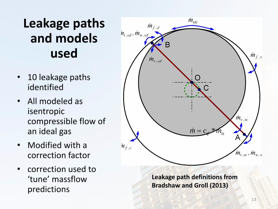
Leakage paths and models
used
• 10 leakage paths identified
• All modeled as isentropic compressible flow of an ideal gas
• Modified with a correction factor
• correction used to ‘tune’ massflowpredictions
13
*tf ism c m
Leakage path definitions from Bradshaw and Groll (2013)

Friction Sub-Models
• Spool Seals (Bradshaw et. al 2015)• Oil shear plus dry friction on rotating endplates
• Tip Seals (Bradshaw 2013)• Oil shear along cylinder bore
• TDC (Bradshaw and Groll 2013)• Oil shear between rotor and cylinder
• Vane (Bradshaw and Groll 2013)• Coulomb friction between vane and rotor slot
• Viscous Drag of Rotating Endplates (Bradshaw et. al 2015)• Drag generated by rotating endplates rotating in enclosed
space with lubricant

Model Predictive Capability, 2 Prototype Platforms
□, □ SEER B/A
□ Superheat
○ Baseline (40/100), 2500 rpm
○ Cond. Temp
○ Evap. Temp
+ Speed
Platform Vdisp (in3)
5th Gen. 2.40
6th Gen. 3.33
MAE = 1.91% MAE = 6.25%

Model Limitations
16
• Valve dynamics and porting• Valve dynamics are
computationally expensive and not used when exploring large spaces
• Port losses are not well captured
• Frictional losses and heat balance• Vane, tip seal, and TDC friction
sub-models difficult to experimentally validate
• More detailed heat flow paths should be added (most pertinent to hermetic and semi-hermetic designs)
Experimentally obtained indicator diagram of 5th generation spool compressor with R410A as the working fluid, from Bradshaw et al., 2015

Improvements Using Model
• Current generation spool (6th Gen.) compared with previous generation (5th
Gen.)
• 5th generation prototype was designed prior to development of modeling tool
• 6th generation utilized modeling tool (described in Bradshaw et al. (2014, 2015)
• Methodology described in 7th generation design study
Overall isentropic efficiency as a function of pressure ratio for the 5th and 6th generation spool compressors (data from Orosz et al. 2014)

Design Study
•Objective: Design a rotating spool compressor for light-commercial air-conditioning•Givens:
1. Design for 40F/100F evaporating and condensing temperatures, respectively
2. Working fluid shall be R134a3. Rotational speed shall be 1750 rpm
•Design Variables: 1. Compressor Displacement (Cooling Capacity)2. Intrinsic Compressor Geometric Variables

Scaling Study• For each displacement, the key geometry was
varied• Eccentricity ratio; Rotor radius/Stator Radius
• Length to diameter ratio; Stator axial length/Stator diameter
• 4 displacements on R134a• 5, 20, 40, 80 Tons
19

Scaling Study, cont’d• Water-cooled conditions (40/100)• 1750 rpm compressor speed • Manufacturing tolerances applied to length
of compressor at 0.0001 in/in• Design rules are incorporated that force
geometry constraints for manufacturing and reliability considerations.• Total eccentricity• Rotor diameter• Eccentric bearing size.
• Calculated displacements, assuming 90% volumetric efficiency
20
Tons 5 20 40 80
Vdisp (in3/rev) 15.48 61.90 123.8 247.6
Vdisp (cm3/rev) 254.7 1014 2029 4057

R134a Results – 5Ton

R134a Results – 20Ton

R134a Results – 40Ton
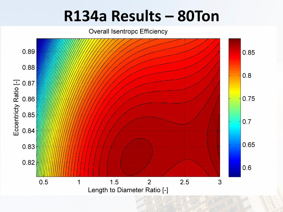
R134a Results – 80Ton

R134a Results – 40Ton
Final Design84.6%

Tip Seal Design
• Used modeling tool developed for tip seals, presented in Bradshaw (2013)
• Matched net tip seal force on cylinder bore per unit axial length relative to the 6th
generation compressor
• Symmetric radius tip
Avg. Force Force/Length Mass Tip Radius
N N/m g mm
6th Gen. 15.1 297 9.5 2.36
40 Ton 74.7 297 39.7 3.81
Free body diagram of tip seal used in design tool, from Bradshaw (2013)

Spool Seal Design• Design tool developed and
validated to evaluate bevel seal designs, presented in Bradshaw et al. (2015)
• Utilized side seal design tool to match a similar face load per unit volume as 6th generation compressor
Vdisp Model Torque
Ratio
cm3 N-cm N/cm2
6th Gen. 54.7 37 1.94
40 Ton 1024 1100 1.56

Results Summary – Best Efficiency Estimates
Cooling Fluid Shaft Eff.* Motor Eff. Total Eff.**
TonsR - % % %
5 134a 77.5% 90.0 67.8%
20 134a 83.9% 91.0 73.5%
40 134a 84.6% 92.0 75.8%
80 134a 87.2% 92.0 78.2%
*Model predicted values**Efficiency uncertainty estimated at roughly 5% points

40 Ton – R134a Design Details
Ecc. Ratio - 0.811
L/D - 1.82
Rotor Dia. in (cm) 4.411 (11.2)
Cylinder Dia. in (cm) 5.440 (13.8)
Cylinder Length in (cm) 9.890 (25.1)
Vane Width in (cm) 1.090 (2.77)
Isentropic Eff. % 84.6
Volumetric Eff. % 92.6
Discharge Temp F (C) 128 (53.3)
Massflow lbm/min (kg/min)
118 (53.5)
Shaft Power kW 23.5
% Carryover Vol. % 1.76
Final Design
• Final design from model requires detailed design work to account for• Strength and resilience• Manufacturability• Location of parts (i.e. ability to
assemble)

Conclusions
• A rotating spool compressor is described
• The spool compressor model and key sub-models are described
• A methodology for compressor design using modeling tools is presented
• The methodology has shown great success between the 5th and 6th generation and now been applied to a 7th generation

Works Cited
• Bradshaw, C.R., Groll, E.A., 2015. Development of a Loss Pareto for a Rotating Spool Compressor Using High-Speed Pressure Measurements and Friction Analysis. Applied Thermal Engineering.(accepted without revision).
• Bradshaw, C.R., Groll, E.A., 2013. A Comprehensive Model of a Novel Rotating Spool Compressor. International Journal of Refrigeration. 36(7), 2007 - 2013.
• Bradshaw, C.R., Orosz, J., Kemp, G., Groll, E.A., 2014. Influence of Volumetric Displacement and Aspect Ratio on the Performance Metrics of the Rotating Spool Compressor. In: Proceedings of the International Compressor Engineering Conference, Purdue University, West Lafayette, IN, USA. No. 1177.
• Bradshaw, C.R., 2013. Spool Compressor Tip Seal Design Considerations. In: 8th International Conference on Compressors and their Systems, City University, London, UK. 341 - 351.
• Orosz, J., Kemp, G., Bradshaw, C.R., Groll, E.A., 2014. An Update on the Performance and Operating Characteristics of a Novel Rotating Spool Compressor. In: Proceedings of the International Compressor Engineering Conference, Purdue University, West Lafayette, IN, USA. No. 1378.

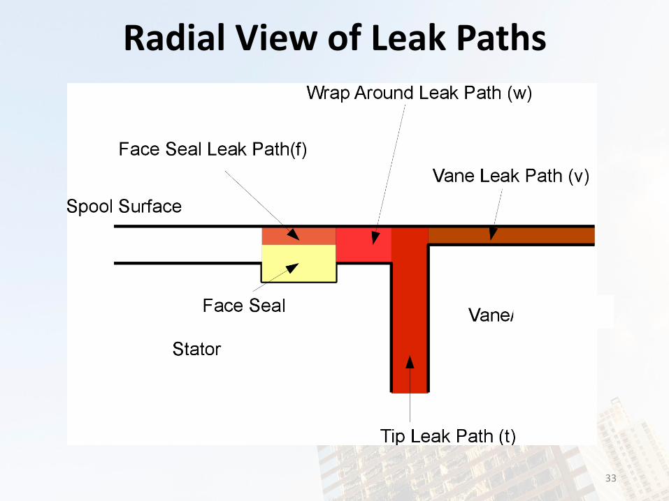
Radial View of Leak Paths
33

Tip Seal Modeling
A similar approach to modeling Wankel Apex seal
Oil film pressure generated by tip seal balanced by pressure and spring forces
Minimum oil film thickness will dictate leakage and torque
34

Spool Seal Modeling
A bevel seal model has been developed which includes oil shear and dry friction components
Model includes:
Static force balance on spool seal
Fluid film pressure reaction of the oil/refrigerant mixture on the sealing surfaces
35

Heat Transfer
• Modified Dittus-Boelter for use in spiral heat exchangers
• raver is rotor radii and hydraulic diameters are a function of crank angle for each chamber
• Reynolds and Prandtl number are a function of crank angle
36

Additional Frictional Losses
• Top Dead Center (TDC)
• Modeled as hydrodynamic oil shear between rotor and cylinder housing
• Vane
• Modeled as Coulomb friction
37

Manufacturing Tolerances in Model
• 0.0001”/” (1 micron/cm) on TDC and wrap-around gaps
• Minimum TDC clearance is 0.0005” (~1.25 micron), so formulation is as follows:
• Same minimum and relationship holds for the wrap-around
0.0005 0.0001*hTDC statorg

Valve Design
• Modified 6th Gen. valve design for improved mechanical reliability
• Modified valve not pictured
• Scaled design to appropriate port size for 40 Ton compressor
• Ran 1 pcs. in reliability test mechanism
Compressor poppet valves, 6th Gen (left) and
40 Ton (right)

Oil Considerations
• Oil properties accounted for in friction analysis in model
• Drag
• Solubility influence on viscosity
• Leakage influence is accounted for to a certain degree and continues to be an area of exploration

Viscous Drag
Drag of an Enclosed Disk from Daily and Nece, 1960

Bearing Loads
• Bearing loads calculated at various head pressures
• Calculated bearing loads used as input to SKF bearing design tool
40 Ton Compressor Simulated Bearing Loads at 38 F Evaporating and 110 F
Condensing
Tevap(C) Tcond(C) ARI Weight Max Load (kN)
Weighted Load(kN)
3.33 53 0.01 33.9 0.34
3.33 43.3 0.42 27.8 11.7
3.33 33.9 0.45 25.1 11.3
3.33 28.3 0.12 24.5 2.93