design, implementation and verification using uml-rt … · design, implementation and verification...
TRANSCRIPT

ISSN 0280-5316ISRN LUTFD2/TFRT--5641-SE
Design, Implementation andVerification using UML-RT in GSM
Radio Base Station 2000
Deb GhatekJohan Olofsson
Departmen of Automatic ControlLund Institute of Technology
May 2000


Document nameMASTER THESISDate of issueMay 2000
Department of Automatic ControlLund Institute of TechnologyBox 118SE-221 00 Lund Sweden Document Number
ISRN LUTFD/2TFRT—5641--SESupervisorMartin Addibpour Ericsson Radio SystemsKarl-Erik Årzén LTH
Author(s)
Deb Ghatek, Johan Olofsson
Sponsoring organization
Title and subtitleDesign, Implementation and Verification using UML-RT in GSM Radio Base Station 2000
Abstract
This work deals with the issue of implementing a UML-RT standard, one of the latestnotations for object oriented specification and design, in the developing-process of new real-timesoftware for Radio Base Stations in the 2000 series at Ericsson. UML-RT is the real-timeextension of the Unified Modeling Language (UML).The thesis investigates the design-, implementation- and verification-problems that exist whencombining the current RT functions, Multi Platform Support, with the UML-RT tool, ObjecTimeDeveloper.We describe UML, look at the advantages and disadvantages of using UML-RT tools andinvestigate current and future possibilities in ObjecTime Developer.
Keywords
Classification system and/or index terms (if any)
Supplementary bibliographical information
ISSN and key title0280-5316
ISBN
LanguageEnglish
Number of pages48
Security classification
Recipient’s notes
The report may be ordered from the Department of Automatic Control or borrowed through:University Library 2, Box 3, SE-221 00 Lund, SwedenFax +46 46 222 44 22 E-mail [email protected]


Preface ii
Preface
This report is a Master's Thesis in automatic control performed at Ericsson Radio Systems inKista. We would specially like to thank Mattin Addibpour and Leif Andersson among othersfor their support during this work.
Ericsson Radio Systems, Stockholm, February 2000
Deb Ghatak,Johan Olofsson
Abbreviations iii
Abbreviations
ERA Ericsson Radio SystemsFSM Finite State MachineGUI Graphical User InterfaceGSM Global System for Mobile communicationMPS Multiple Platform SupportMSC Master Sequence ChartOS Operating SystemPLS-Sim PLatform Subsystem SimulatorRBS Radio Base StationROOM Real-time Object Oriented ModelingRTS Run Time SystemSK Soft KernelSU Software UnitUML Unified Modeling LanguageUML-RT Unified Modeling Language for Real-TimeWCDMA Wideband Code Division Multiple Access

Contents iv
Contents
1. INTRODUCTION ............................................................................................................................................. 1
1.1 BACKGROUND ................................................................................................................................................ 11.2 PROBLEM SPECIFICATION............................................................................................................................... 21.3 OBJECTIVES.................................................................................................................................................... 21.4 LIMITATIONS .................................................................................................................................................. 2
2. UML FOR MODELING REAL-TIME SYSTEMS ....................................................................................... 3
2.1 INTRODUCTION............................................................................................................................................... 32.2 THE UNIFIED MODELING LANGUAGE............................................................................................................. 4
2.2.1 Introduction ............................................................................................................................................ 42.2.2 UML Diagrams....................................................................................................................................... 42.2.3 Use-Case Diagrams................................................................................................................................ 42.2.4 Class Diagrams ...................................................................................................................................... 42.2.5 State Transition Diagrams...................................................................................................................... 52.2.6 Interaction Diagrams ............................................................................................................................. 6
2.2.6.1 Sequence Diagrams ...........................................................................................................................................62.2.6.2 Collaboration Diagrams.....................................................................................................................................72.2.6.3 Activity Diagrams..............................................................................................................................................7
2.2.7 Package Diagram................................................................................................................................... 82.2.8 Deployment Diagrams............................................................................................................................ 9
2.3 HOW UML DIAGRAMS FIT TOGETHER........................................................................................................... 92.4 REAL-TIME OBJECT MODELING: ROOM ..................................................................................................... 10
2.4.1 Introduction .......................................................................................................................................... 102.4.2 The Method........................................................................................................................................... 112.4.3 Modeling Structure ............................................................................................................................... 112.4.4 Modeling Behaviour ............................................................................................................................. 12
2.5 DESIGNING UML SYSTEMS.......................................................................................................................... 132.5.1 Representing Physical Architecture in UML ........................................................................................ 14
2.5.1.1 Distribution of Control in Systems ..................................................................................................................152.5.1.2 Communication Infrastructure .........................................................................................................................16
2.5.2 Mechanistic design ............................................................................................................................... 162.5.3 Detailed Design .................................................................................................................................... 17
3. OBJECTIME- A BRIEF OVERVIEW (OF THE C-VERSION) ............................................................... 18
3.1 INTRODUCTION............................................................................................................................................. 183.2 WHY USE OBJECTIME?................................................................................................................................. 18
ObjecTime term...........................................................................................................................................................19Equivalent UML-RT term ...........................................................................................................................................19
3.3 HOW TO USE OBJECTIME?............................................................................................................................ 213.3.1 Run-Time Services (RTS)...................................................................................................................... 21
3.4 WHAT DOES OBJECTIME CONSIST OF?.......................................................................................................... 223.4.1 Software Components ........................................................................................................................... 223.4.2 Real-world and virtual models ............................................................................................................. 23
3.4.2.1 Actors ..............................................................................................................................................................233.4.2.2 Messages..........................................................................................................................................................243.4.2.3 Actor Classes ...................................................................................................................................................253.4.2.4 Inheritance .......................................................................................................................................................253.4.2.5 Actor Structure ................................................................................................................................................263.4.2.6 Actor Behavior ................................................................................................................................................273.4.2.7 Ports and Bindings...........................................................................................................................................283.4.2.8 Data Objects ....................................................................................................................................................29
4. EXTERNAL COMMUNICATION IN OBJECTIME................................................................................. 30
4.1 MAKING OBJECTIME COMMUNICATE WITH EXTERNAL SYSTEMS. ................................................................ 304.1.1 Communication..................................................................................................................................... 31
4.1.1.1 Compilation .....................................................................................................................................................314.1.1.2 Synchronization of ObjecTime and MPS processes ........................................................................................314.1.1.3 Addressing.......................................................................................................................................................324.1.1.4 Initiation ..........................................................................................................................................................32

Contents v
4.1.2 Function implementation...................................................................................................................... 324.1.2.1 Proxy................................................................................................................................................................324.1.2.2 SAP/SPP..........................................................................................................................................................334.1.2.3 Inline coding....................................................................................................................................................344.1.2.4 Port send (unbound).........................................................................................................................................344.1.2.5 Function call ....................................................................................................................................................34
4.2 TARGET OBSERVABILITY ............................................................................................................................. 354.3 RESULTS....................................................................................................................................................... 37
5. UML AND OBJECTIME AT ERICSSON RADIO SYSTEMS.................................................................. 39
6. SUMMARY...................................................................................................................................................... 41
REFERENCES .................................................................................................................................................... 43
APPENDIX A ...................................................................................................................................................... 44

List of Figures vi
List of FiguresFIGURE 2.1 UML DEVELOPMENT PROCESS .............................................................................................................. 3FIGURE 2.2 USE-CASE DIAGRAM; LIBRARY ............................................................................................................. 4FIGURE 2.3 CLASS DIAGRAM; LIBRARY ................................................................................................................... 5FIGURE 2.4 STATE TRANSITION DIAGRAM; WATCH................................................................................................. 5FIGURE 2.5 SEQUENCE DIAGRAM; LIBRARY............................................................................................................. 6FIGURE 2.6 COLLABORATION DIAGRAM; LIBRARY .................................................................................................. 7FIGURE 2.7 ACTIVITY DIAGRAM; STOCK TRADE...................................................................................................... 8FIGURE 2.8 PACKAGE DIAGRAM; STOCKS DATA BASE EXAMPLE............................................................................. 8FIGURE 2.9 DEPLOYMENT DIAGRAM; INTERNET ...................................................................................................... 9FIGURE 2.10 ITERATIVE DEVELOPMENT WITH UML MODELING TECHNIQUES........................................................ 10FIGURE 2.11 SERIAL DEVELOPMENT WITH UML MODELING TECHNIQUES............................................................. 10FIGURE 2.12 BASIC ENTITIES IN THE ROOM NOTATION......................................................................................... 12FIGURE 2.13 HIERARCHICAL DESIGN WITH ACTORS AND SUBACTORS.................................................................... 12FIGURE 2.14 FINITE STATE MACHINE..................................................................................................................... 13FIGURE 2.15 FINITE STATE MACHINE; SET TIME.................................................................................................... 13FIGURE 2.16 DESIGNING UML SYSTEMS ............................................................................................................... 14FIGURE 2.17 CENTRALIZED CONTROL .................................................................................................................... 15FIGURE 2.18 MESSAGE SEQUENCE CHART, CENTRALIZED CONTROL ..................................................................... 15FIGURE 2.19 DECENTRALIZED CONTROL ................................................................................................................ 16FIGURE 2.20 MESSAGE SEQUENCE CHART, DECENTRALIZED CONTROL................................................................. 16FIGURE 2.21 CLASS EXAMPLE ................................................................................................................................ 17FIGURE 3.1 COMPARISON OF OBJECTIME AND UML-RT NOTATION...................................................................... 19FIGURE 3.2 OBJECTIMES GUI ................................................................................................................................ 20FIGURE 3.3 OBJECTIMES GUI EXPLANATION......................................................................................................... 20FIGURE 3.4 WORKFLOW IN OBJECTIME ................................................................................................................. 22FIGURE 3.5 REUSABLE SOFTWARE COMPONENTS ................................................................................................... 22FIGURE 3.6 ACTORS ............................................................................................................................................... 23FIGURE 3.7 MESSAGES........................................................................................................................................... 24FIGURE 3.8 ACTOR CLASSES.................................................................................................................................. 25FIGURE 3.9 INHERITANCE....................................................................................................................................... 26FIGURE 3.10 ACTOR STRUCTURE ........................................................................................................................... 27FIGURE 3.11 ACTOR BEHAVIOR.............................................................................................................................. 28FIGURE 3.12 PORTS AND BINDINGS........................................................................................................................ 28FIGURE 3.13 DATA OBJECTS .................................................................................................................................. 29FIGURE 4.1 SYSTEM PARTS AND RELATIONS .......................................................................................................... 30FIGURE 4.2 PROXY SOLUTION................................................................................................................................ 33FIGURE 4.3 OBJECTIME VIEWS .............................................................................................................................. 36FIGURE A 1 TRU MODEL........................................................................................................................................ 44FIGURE A 2 EXAMPLE OF ACTORS AND THEIR BEHAVIUOR IN THE TRU MODEL.................................................... 44FIGURE A 3 MSC OF SELECTED ACTORS OF THE TRU MODEL................................................................................ 45
1. Introduction 1
1. Introduction
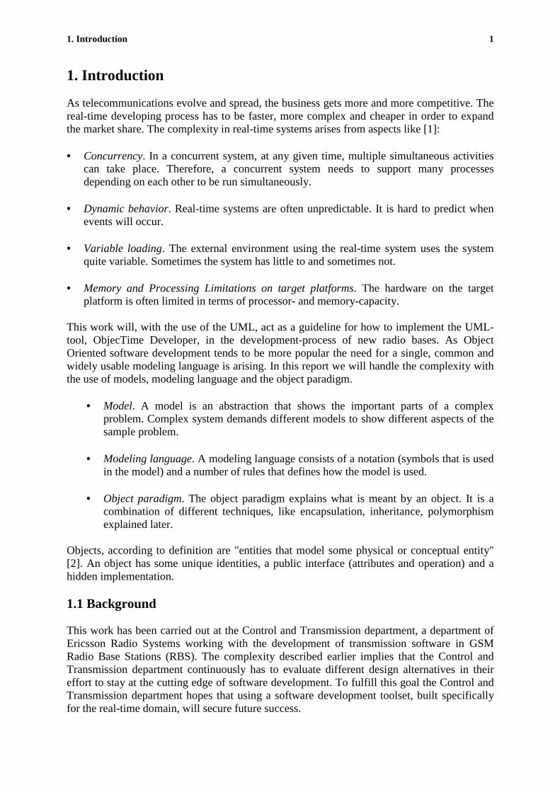
As telecommunications evolve and spread, the business gets more and more competitive. Thereal-time developing process has to be faster, more complex and cheaper in order to expandthe market share. The complexity in real-time systems arises from aspects like [1]:
• Concurrency. In a concurrent system, at any given time, multiple simultaneous activitiescan take place. Therefore, a concurrent system needs to support many processesdepending on each other to be run simultaneously.
• Dynamic behavior. Real-time systems are often unpredictable. It is hard to predict whenevents will occur.
• Variable loading. The external environment using the real-time system uses the systemquite variable. Sometimes the system has little to and sometimes not.
• Memory and Processing Limitations on target platforms. The hardware on the targetplatform is often limited in terms of processor- and memory-capacity.
This work will, with the use of the UML, act as a guideline for how to implement the UML-tool, ObjecTime Developer, in the development-process of new radio bases. As ObjectOriented software development tends to be more popular the need for a single, common andwidely usable modeling language is arising. In this report we will handle the complexity withthe use of models, modeling language and the object paradigm.
• Model. A model is an abstraction that shows the important parts of a complexproblem. Complex system demands different models to show different aspects of thesample problem.
• Modeling language. A modeling language consists of a notation (symbols that is usedin the model) and a number of rules that defines how the model is used.
• Object paradigm. The object paradigm explains what is meant by an object. It is acombination of different techniques, like encapsulation, inheritance, polymorphismexplained later.
Objects, according to definition are "entities that model some physical or conceptual entity"[2]. An object has some unique identities, a public interface (attributes and operation) and ahidden implementation.
1.1 Background
This work has been carried out at the Control and Transmission department, a department ofEricsson Radio Systems working with the development of transmission software in GSMRadio Base Stations (RBS). The complexity described earlier implies that the Control andTransmission department continuously has to evaluate different design alternatives in theireffort to stay at the cutting edge of software development. To fulfill this goal the Control andTransmission department hopes that using a software development toolset, built specificallyfor the real-time domain, will secure future success.

1. Introduction 2
Due to the rapid development of hardware platforms Ericsson Radio continuously investigatehow to use these for their new Radio Bases. In the RBS system software design changes areneeded because of these new hardware platforms, which implies new product configurationsand limitations in the current software design. In the RBS system there are a lot of softwarethat is hardware dependent and the software development has grown bigger and morecomplex. The goals are long term cost efficient solutions, possibilities to reuse software andsupporting many products.
1.2 Problem Specification
The core problem in this thesis was to implement a UML tool, ObjecTime Developer, in thedesign and implementation phases
1.3 Objectives
The main objective of this thesis, is to enable external execution of existing real-timefunctions within ObjecTime, so that future development can be done in Objectime. One partobjective was to create a communication link from ObjecTime to a simulator, PlsSim(HOST). The second part-objective was to implement the solution on an AMD targetprocessesor. Future developments of radio bases at Ericsson will be made on PowerPC’s, soafter developing this Ericsson wanted to implement the same solutions on a PowerPC.
1.4 Limitations
This thesis will not try to explain the ObjecTime Developer environment, as this is betterdone working through a tutorial.
Neither will it describe the TRU model, described in Appendix A, since it is of specificinterest only to those who works at Ericsson Radio, and of little interest to others.
The development environment on Power PC?s hasn?t been finalisedyet, sowe nevewrimplemented the solution on a Power PC, however itwould havebeen done in the samemanner as the AMD.

2. UML for Modeling Real-Time Systems 3
2. UML for Modeling Real-Time Systems
2.1 Introduction
“Developing a model for an industrial strength software system prior to its construction orrenovation is as essential as having a blueprint for a large building” [4]. In large and complexreal-time software systems it’s crucial to design the software with a sound architecture.
A good architecture simplifies the construction of the system and accommodates changesduring the development process. A good modeling language includes fundamental modelingconcepts/semantics and visual rendering of model elements. In figure 2.1 is UML used toform the requirements model and the design model. To translate the design model intoObjecTime code the ROOM notation is used. ObjecTime deploys an executable model thatcan be run in the Real-Time Services packages included in ObjecTime.
“.. UML is hot. People new to object and component development want an overview andthat’s exactly what UML provides. It provides diagrams that describe the basic perspectivesthat OO and component designers routinely create to capture the important elements of theapplication they create”[3]. The Unified Modeling Language (UML) is a language forspecifying, constructing, visualizing and documenting the artifacts of a software-intensivesystem. UML is appropriate for object-oriented software development because it providessupport for modeling classes, objects and the many relationships among them, includingassociation, aggregation, inheritance, dependency and instantiation.
Modeler
Figure 2.1 UML Development process
Node
Compilation
RequirementModel
DesignModel
DesignInterface
UML VirtualMachine
Run TimeInterface
Executable Model

2. UML for Modeling Real-Time Systems 4
2.2 The Unified Modeling Language
2.2.1 Introduction
The UML is recognized as a modeling language and not a methodology or method. Thedifference is that a methodology contains recommendations on object-oriented notation anddesign, while a modeling language is a vocabulary or notation on how to express the design.
2.2.2 UML Diagrams
When designing and developing software systems in UML nine different diagrams can beused. Different projects needs different diagrams. The diagrams form a skeleton of thecomplete design. They describe different aspects of the system as well as different steps in thedevelopment process. To get the full picture one must know what the diagrams shows andhow to combine them. In Chapter 2.2.3 to 2.2.8 the different types of diagrams will beexplained.
2.2.3 Use-Case Diagrams
A use case diagram provide a way of describing an external view of a system and itsinteraction with the outside world, it documents the behaviour of a system from the user’spoint of view. Figure 2.2 describes the outside world as actors, an user/actor can be a personor an another information system or a hardware device. A user/actor can have more than onerole, and there may be many roles playing in it. The use-case diagram describes theinteraction between the actor and the described system.
Figure 2.2 Use-Case Diagram; Library
Scenarios are instances of a use case, just as objects are instances of classes, In this way, usecase diagrams are like class-diagrams they show the logical static structure of scenarios .
2.2.4 Class Diagrams
The class diagram is a central modeling technique that is used in most object-orientedmethods. A class diagram shows the classes (sometimes objects) and relationships betweenclasses and between objects. It is easy to follow the relationship between a book at a libraryand a staff member in the class diagram illustrated in Figure 2.3.
Cash withdrawal
Transfer Funds
Deposit
System Starts
Customer
ATM Operator
Bank System(non-human
actor)
2. UML for Modeling Real-Time Systems 5
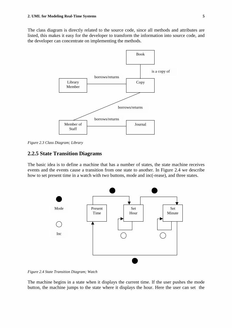
The class diagram is directly related to the source code, since all methods and attributes arelisted, this makes it easy for the developer to transform the information into source code, andthe developer can concentrate on implementing the methods.
Figure 2.3 Class Diagram; Library
2.2.5 State Transition Diagrams
The basic idea is to define a machine that has a number of states, the state machine receivesevents and the events cause a transition from one state to another. In Figure 2.4 we describehow to set present time in a watch with two buttons, mode and inc(-rease), and three states.
Figure 2.4 State Transition Diagram; Watch
The machine begins in a state when it displays the current time. If the user pushes the modebutton, the machine jumps to the state where it displays the hour. Here the user can set the
Book
Journal
Copy
Member ofStaff
LibraryMember
is a copy of
borrows/returns
borrows/returns
borrows/returns
Mode
Inc
PresentTime
SetMinute
SetHour

2. UML for Modeling Real-Time Systems 6
hour by pushing the inc button. Another push on the mode button makes it possible to set theminutes. A final push on the mode button and the machine jumps back to the initial state.
The big disadvantage with State Transition Diagrams, is that one has to define all the possiblestates of a system. In small systems this is not a problem, but in larger systems the StateTransition Diagrams become far too complex. Many object-oriented methods (e.g.ObjecTime) define separate state transitions for each class. State models are excellent fordescribing the behaviour of a single object, but not to describe whole systems.
2.2.6 Interaction Diagrams
Interaction Diagrams can be divided into three different forms of diagrams: sequencediagrams, collaboration diagrams, and activity diagrams.
A typical interaction diagram describes how a group of objects collaborate in some behavior.The diagram shows objects and the messages that are passed between them. Interactiondiagrams are best used when you want to look at the behaviour in a single use case, but not sogood in precise definition of the behaviour.
2.2.6.1 Sequence Diagrams
In this diagram the objects are shown as vertical lines (Figure 2.5) with the messages ashorizontal lines between them. The messages can be an operation, a signal, a procedure call,or anything that starts an activity at the reception.
Figure 2.5 Sequence Diagram; Library
Borrow Copy
Book borrower
LibraryMember
The Copy The Book
Borrow OK
Borrow
Borrowed

2. UML for Modeling Real-Time Systems 7
The sequence diagram is a description for a single use case scenario. This is helpful when wewant to understand the logic of the operations during the design phase. As in the libraryexample, the last transition registers that a copy of a certain book is borrowed.
2.2.6.2 Collaboration Diagrams
Figure 2.6 Collaboration Diagram; Library
The collaboration diagram shows the message flow between the classes and it numbers themessages in sequence.
A collaboration diagram, Figure 2.6, is often used as a complement to the class diagram, sincethey don’t show the message flow between the classes. The rectangles represent the variousobjects in your application, and the arrow represents the flow of the message. The numberingof the messages makes it easy for the viewer/developer to see the many different usecasescenarios of the system.
2.2.6.3 Activity Diagrams
The Activity Diagram focuses on activities and the coordination of those activities, it is quitesimilar to the state chart diagram. It is a form of flowchart, but the difference is that theactivity diagram supports parallel activities and their synchronization.
In the figure a stock-ordering procedure is illustrated. Parallelism is illustrated as a paymentprocess paralell to the stock assignment process. Both processes have to be completed in orderto settle an affair.
The Book
LibraryMember
The Copy
Book borrower
Borrow Copy
1: Borow OK
2: Borrow
2.1: Borrowed

2. UML for Modeling Real-Time Systems 8
Figure 2.7 Activity Diagram; Stock Trade
2.2.7 Package Diagram
The package diagram has to do with the implementation of the system. In this technique weput each class in a single package. If a class uses another class in a different package, we haveto draw a dependency line to that package. As seen in Figure 2.8 the ’Stock Pricer UI’ dependboth on the ’GUI Library’ and the ’Stock Pricer’.
Figure 2.8 Package Diagram; Stocks Data Base example
Stocks PricerUI
GUILibrary
Portfolio UI
PortfolioApplication
ScenarioManager
Positions
Stocks Pricer
StocksDataBase
Dependencies
Packages
ReceiveOrder
Assign Stocksto Portfolio
Cancel OrderAuthorizePayment
ReorderStocks
Dispatch Order
[failed]
[succeded]
[Need To Reorder]
[Pick Order]
[Stocks assigned and payment authorized]
2. UML for Modeling Real-Time Systems 9
UML does not treat package diagrams as a separate technique, it rather treats them as icons ina class diagram.
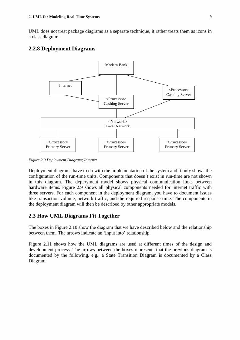
2.2.8 Deployment Diagrams
Figure 2.9 Deployment Diagram; Internet
Deployment diagrams have to do with the implementation of the system and it only shows theconfiguration of the run-time units. Components that doesn’t exist in run-time are not shownin this diagram. The deployment model shows physical communication links betweenhardware items. Figure 2.9 shows all physical components needed for internet traffic withthree servers. For each component in the deployment diagram, you have to document issueslike transaction volume, network traffic, and the required response time. The components inthe deployment diagram will then be described by other appropriate models.
2.3 How UML Diagrams Fit Together
The boxes in Figure 2.10 show the diagram that we have described below and the relationshipbetween them. The arrows indicate an ‘input into’ relationship.
Figure 2.11 shows how the UML diagrams are used at different times of the design anddevelopment process. The arrows between the boxes represents that the previous diagram isdocumented by the following, e.g., a State Transition Diagram is documented by a ClassDiagram.
Modem Bank
<Processor>Primary Server
<Processor>Primary Server
<Processor>Primary Server
Internet
<Processor>Cashing Server
<Processor>Cashing Server
<Network>Local Network

2. UML for Modeling Real-Time Systems 10
Figure 2.10 Iterative Development with UML modeling techniques
Figure 2.11 Serial Development with UML modeling techniques
2.4 Real-Time Object Modeling: ROOM
2.4.1 Introduction
In ROOM, there is a mix of advanced object oriented concepts and well-tested methods forreal-time development. In ROOM you work with models (UML diagrams described earlier)that are executable and used to transform the requirements to an implementation. Models aretranslated to programs that can be executed in simulators on workstations or on target
PackageDiagram
Use CaseDiagram
State TransitionDiagram
Use Cases
ClassDiagram
DeploymentDiagram
CollaborationDiagram
SequenceDiagram
Use CaseDiagram
DeploymentDiagram
CollaborationDiagram
Source CodeSequenceDiagram
Use Cases
State TransitionDiagram
ClassDiagram
PackageDiagram
User Requirements Analysis Design Code

2. UML for Modeling Real-Time Systems 11
machines with a real-time operating systems. ROOM is the base in UML-RT, the real-timeextension of UML. The development process is often done in an iterative manner. You workwith component-based models that are successively refined through a couple of iterations. Ineach step integration and verification of the models are done to ensure stability with thespecification validated in an earlier stage. In this manner the system is tested thoroughly ineach step of the development process
2.4.2 The Method
In ROOM you build a model with development tools like ObjecTime. ROOM has liketraditional programming languages a syntax to express domain specific knowledge and designideas. ROOM is object oriented with concepts chosen for event driven real time applications.As mentioned in 2.4.1 one can throughout the development process generate executablemodels.
The fundamental concepts of ROOM are objects, called actors that communicate with eachother sending messages solely through interface ports defined by some protocol. To managecomplexity, a structure can be hierarchically created, i.e. actors may contain other actors.Actors can also be created dynamically, i.e. actors are created and destroyed at run-time. Thisimplies a system structure in constant change. In addition to structure an actor has a state-machine expressing its behaviour, i.e. its reactions to events. In addition to this, ROOM usesinheritance to describe variations of objects. Variations can be changes on structure,behaviour, as well as different protocols and data. To these, all graphical, concepts, ROOMuses traditional programming languages to explain detailed structure and behaviour. Forexample, high-level languages such as C or C++ are used to describe actions taken on eventsin a state-machine. This is powerful due to the use of a combination of graphical concepts andtraditional high-level languages. Developers can use the same concepts for all activities, fromanalysis to implementation. The semantic gap common in traditional analysis implementationmethods is reduced. From analysis and design to implementation there are only iterativerefinements in contrast to the mappings between different representations used in traditionalanalysis-design-implementation methods.
2.4.3 Modeling Structure
A ROOM structure describes communication relationships between actors in a system. Anactor is the primary concept in a structure. Actors are parallel objects that can exist andexecute independently of other actors in the same environment. Actor implementations areencapsulated. Actors can be of two types: static or dynamic. In a static actor there is a one-to-one relationship between objects in the design and objects that actually execute at run-time.Dynamic actors are objects created and destroyed dynamically at run-time. Actorscommunicate with messages sent solely through ports. A port can be described as an openingin the encapsulation allowing the actor to communicate with other actors. A message containsa signal and a message body, i.e. an instance of a data class. A port is a specialized interfacefor an actor using a protocol. A protocol is a set of messages allowed to be sent through theport. Ports are instances of a protocol class allowing the reuse of interfaces or refinementthrough the inheritance mechanism.

2. UML for Modeling Real-Time Systems 12
Figure 2.12 Basic entities in the ROOM notation
To mediate communication among actors ports are connected to each other with aconstruction called binding. A binding is like a communication channel that mediates themessage sent by actors through its ports. A binding shows explicit communication pathsbetween actors. Note that two actors can only communicate with each other if there exists abinding between them. The fact that actors communicate solely through ports instead ofdirectly to eachother, makes it possible to view the actor as a black box independent of it’soutside environment. This leads to actors that are inherently distributable and highly reusablein different design situations. Actors also take part in the concept of aggregation. Aggregationmakes it possible to create arbitrary complex objects. In Figure 2.13, actor 4 and actor5 areleave actors, i.e. they do not contain any other actor. On the other hand instances of actor4 andactor5 are contained in the higher level actor3. This is displayed with a little symbol in thelower left of actor3. Actor3 and actor2 are contained in the even higher level actor actor1.ROOM allows the creation of arbitrary number of levels in the structure hierarchy. This isquite powerful when complex systems are to be modeled: it is easy to give an overall view ofthe system on a top-level structure, hiding the details in lower level hierarchies.
Figure 2.13 Hierarchical Design with actors and subactors
2.4.4 Modeling Behaviour
Behaviour expresses what actions an actor should take when messages arrive on its ports.ROOM uses extended hierarchical state machines, modified to manage object orientation andeffective real-time implementations. In Figure 2.14 the principle of a state machine isexplained. The state machine has three transitions: initialize, request and timeout, and twostates. Idle and Handle. The initialize transition is fired when the actor starts up and are usedto bring the actor to its operational state. The Watch example in Figure 2.4 would have beenimplemented in ROOM as seen in Figure 2.15.
Actors
Ports
Binding
Actor 2 Actor 5Actor 4Actor 3
Actor 1 Actor 3

2. UML for Modeling Real-Time Systems 13
Figure 2.14 Finite State Machine
In this manner arbitrary complex behaviors can easily be hierarchically decomposed making iteasy to express complexity and making state-machines easy to read and maintain.
Figure 2.15 Finite State Machine; Set Time
As mentioned earlier the detailed behavior are the actions to be taken in the transitionsbetween states. This is not expressed graphically.
Tools supporting the ROOM method, such as the ObjecTime toolset does combine thegraphical representation with the text-based code in a graphical environment. The developerjust click on a transition to bring up a text-editor where code easily can be written.
2.5 Designing UML Systems
“Designing a notation for use in object-oriented analysis and designs is not unlike designing aprogramming language”[8]. When designing with UML we divide the process into threedifferent categories: architectural, mechanistic, and detailed design (Figure 2.16). Thearchitectural design, designs software structures such as subsystems, packages and tasks,while the mechanistic design includes the design of mechanisms composed of classes workingtogether to achieve common goals. Detailed design specifies the internal primitive datastructures and algorithms within individual classes.
initialize
Idle Handle
request
timeout
mode
mode
Present Time Set Hour
mode
Set Minute
Inc Inc

2. UML for Modeling Real-Time Systems 14
Figure 2.16 Designing UML Systems
2.5.1 Representing Physical Architecture in UML
In UML we represent physical architectures with deployment diagrams. The most importantobject in deployment diagrams is the node. A node can represent processors, sensor, anddisplays as seen in the ObjecTime implementation in Figure 4.7. Interconnections in thediagram represent physical interconnections were information (signals) is sent. Processornodes may contain classes and objects, but can also be broken down into to subpackages andtasks. These subpackages ultimately contain objects and classes.
Architectural Design: Processes (Nodes), Packages, Tasks
Node Package Task
Mechanistic Design: Groups of collaborating classes
classclass
classclass
Detailed Design: Class
Class Name
Attributes
Operations
2. UML for Modeling Real-Time Systems 15
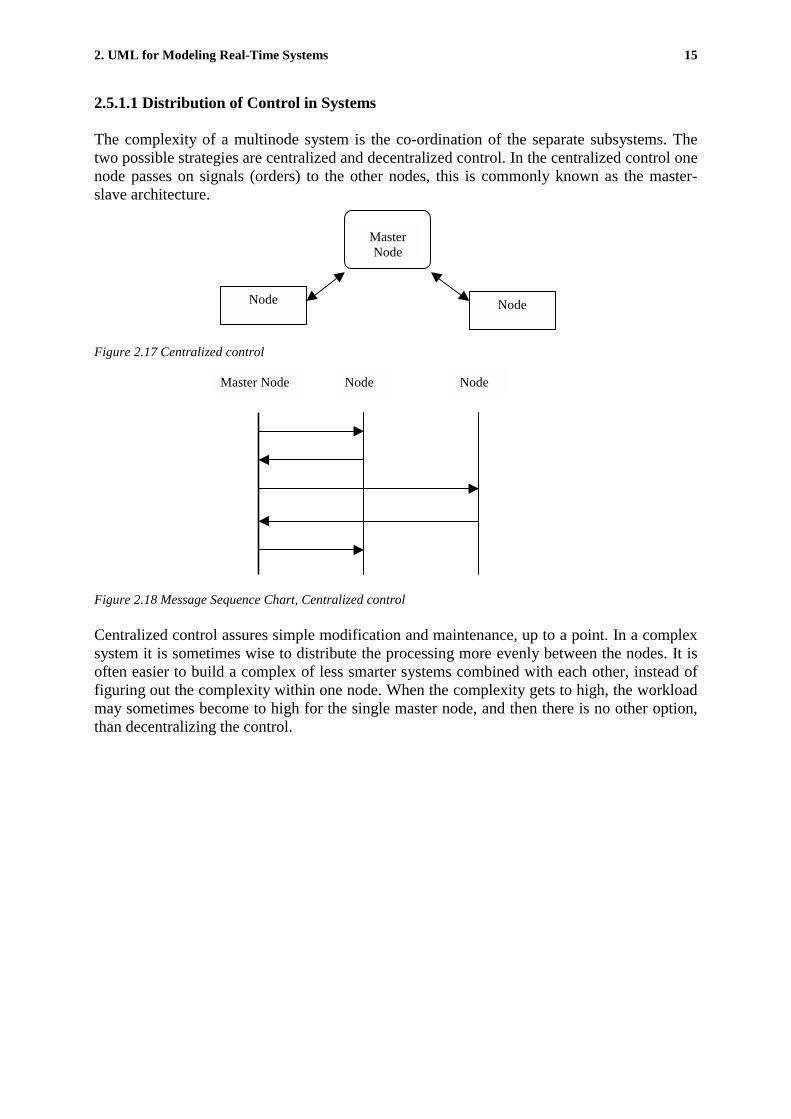
2.5.1.1 Distribution of Control in Systems
The complexity of a multinode system is the co-ordination of the separate subsystems. Thetwo possible strategies are centralized and decentralized control. In the centralized control onenode passes on signals (orders) to the other nodes, this is commonly known as the master-slave architecture.
Figure 2.17 Centralized control
Figure 2.18 Message Sequence Chart, Centralized control
Centralized control assures simple modification and maintenance, up to a point. In a complexsystem it is sometimes wise to distribute the processing more evenly between the nodes. It isoften easier to build a complex of less smarter systems combined with each other, instead offiguring out the complexity within one node. When the complexity gets to high, the workloadmay sometimes become to high for the single master node, and then there is no other option,than decentralizing the control.
Node Node
MasterNode
NodeNodeMaster Node

2. UML for Modeling Real-Time Systems 16
Figure 2.19 Decentralized control
Node Node Node
Figure 2.20 Message Sequence Chart, Decentralized control
2.5.1.2 Communication Infrastructure
When we use a multiprocessor (multinode) system, we require a communication path linkingthe processors to each other. Two separate but related issues are the bus topology and theprotocol operating over the bus. The protocol defines what rules, formats (of signals) andprocedures that the communicating objects have agreed on. There are different types ofprotocols, Data driven protocols are highly specialized and concentrate on the communicatedinformation, this makes it simple and efficient; Grammar driven protocols concentrate moreon what is said than the specific things themselves, the generality of the latter protocol makesthen flexible but not as efficient as the previous.
2.5.2 Mechanistic design
Mechanistic design deals with how small sets of classes and objects collaborate to achievecommon goals. A real-time system has multiple mechanisms operating concurrently. Whenthe models and classes of the system have been defined, we use mechanistic design to addobjects to facilitate their collaboration. An autopilot may use many sensors and actuators, ifwe have a common one-to-one association, the common solution is to have a pointer orreference in the client that sends a message to the server.
Node Node
Node

2. UML for Modeling Real-Time Systems 17
class Actuator { class Autopilot { int value; Actuator *s;public: public: int gimme(void) {return value; }; void AutoPilot(Server *YourActuator) : s (YourActuator) void set(int v) { value = v; }; }; {};
// send message to Server object s void setIt(int a) { s->set(a); }
void IncIt(void) { int a = s->gimme();
s->set(++a); };};
Figure 2.21 Class example
The class Autopilot uses pointers to locate its Actuator object and it sends the object messageslike s-> set(a) and s->gimme() as above. Here we use a simple pointer since this is a one-to-one association, but the situation changes when the association is one to several. It is fullypossible to collect the Actuator objects directly in the Autopilot class, with linked-lists orbinary trees. But the drawbacks of such a solution are that the Autopilot class has to handle atask that is totally unrelated to the Autopilot task. If the handling of the collection is complexwe will make the Autopilot class complex as well. [10] If the system has several classes withmultivalued roles, we have to rewrite the behavior for each class. However duringmechanistic design we can add a new class, a collection class. This solution enables us tochange the type of collection easily. Remember that the analysis model identified theassociation and it’s multiplicity, but the use of a separate collection class is a design decision.
2.5.3 Detailed Design
The fundamental unit of decomposition in object-oriented systems is the object. Some objectsare fairly simple, while other objects needs detailed design to be implemented correctly oroptimize the performance. The decisions in detailed design will concern, data structures,implementation of associations, algorithms, etc. This is nothing that is specific to an UMLReal-Time system, but appears in all sorts of software development, so we won’t go furtherinto this subject.

3. ObjecTime- A brief overview (of the C-version) 18
3. ObjecTime- A brief overview (of the C-version)
3.1 Introduction
ObjecTime, which is developed by Rational, and is a software development tool based onUML design and the ROOM notation. It is well suited for designing and implementing real-time systems. A defining property of real-time systems is that they require responding tocertain inputs within a predefined time interval. In a real-time system, one has to monitor andcontrol the time resources very closely. Given the criticality of time in such systems, it isunfortunate that there are very few facilities available to improve the predictability of timeutilization during software design and development. This situation is particularly problematicfor concurrent systems in witch it is very difficult to rely on intuition about temporalproperties.
There are two basic sets of techniques that address this issue:
• Analytical techniques are based on the construction of a formal mathematical model of thesystem and the use of mathematical algorithms to determine a system's performancecharacteristics.
• Simulation techniques are based on the construction of a computer-executable model of asystem from which the performance characteristics are extracted by measurement.
Analytical techniques tend to be more rigorous but are usually quite complex and requiremathematical expertise beyond the training of most software designers. Also, most of thesetechniques do not scale up to large systems so that they can only be applied either at a veryhigh level of abstraction or they are applied at subsets of the system.
At present, the use of ObjecTime for performance modeling is based purely on simulationtechniques. Several specialized features have been provided in ObjecTime especially for thispurpose.
It is important to notice that ObjecTime is not intended to be used as a primary performance-modeling tool. Its current capabilities in that regard is generally not as extensive as found inmost professional tools created expressly for that purpose. Instead, they provide a low-overhead facility for quick (but not necessarily extensive) insight into the performanceproperties of the system under construction. The overhead is low because, instead of buildinga separate model of the system, the ObjecTime design itself can be used for this purpose withlittle or no extra work required. This enables performance analysis to be tightly integratedwith the analysis and design activities.
3.2 Why use ObjecTime?
ObjecTime itself is a powerful graphical modeling environment for the object-oriented designand simulation of real-time systems. It is easy to get to know and has a smooth user-interfacethat makes it ideal for rapid prototyping of distributed, event-driven systems usingsynchronous or asynchronous communication, and the development of efficientimplementations for execution on the real-time platform. The Graphical User Interface, GUI,enables developers to work fast and with a good overhead of the system. "Good programmers

4. External communication in ObjecTime 19
that understand ObjecTime are able to work three or four times faster than they could in anysimilar environment,.." [6]. The implementation is generated directly from the toolset, so thatthe implementation always stays in sync with the model.
ObjecTime Developer's graphical models provide a high-level, easy- to-understandenvironment for communicating requirements and design among developers, managers andcustomers. New team members can become familiar with designs faster by examining them atthe higher levels then by dealing with details. [7]
Since ObjecTime is based on the UML/ROOM notation and thereby supports object orientedimplementation, designing, both structure and behavior, is done graphically in a fashion thatclosely corresponds to the implementation in ObjecTime. (The GUI, graphical user interface,can be seen in Figure 3.2). “.. a well-designed architecture is not only one that simplifiesconstruction of the initial system, but more importantly, one that easily accommodateschanges forced by new system requirements”[9]. A comparison of ObjecTime and UML-RTnotation is included in the table below. (Since there are no major differences between theUML and ROOM notations, and UML is the method that are to be used in forthcomingversions of ObjecTime/RationalRose the table shows the UML notations.)
ObjecTime term Equivalent UML-RT termActorActorOptional ActorImported ActorActor StructureActor BehaviorReplication FactorPortPort TypeUnconjugated ProtocolConjugated ProtocolBindingChoice PointJoin PointInitial PointData ClassExternal ClassMSC
CapsuleReference SubCapsuleOptional SubCapsulePlug-in SubCapsuleCapsule StructureCapsule BehaviorMultiplicityPort RoleProtocol RoleProtocol Base RoleProtocol Conjugated RoleConnectorBranch PointChain StateInitial StateClassClassSequence Diagram
Figure 3.1 Comparison of ObjecTime and UML-RT notation
The structure and behavior of a model in ObjecTime are described as a Finite State Machine(FSM) that shows in which order events are handled and what to do when different eventsoccur. The structure and behavior editors are illustrated in Figure 3.2 and 3.3. Unfortunately,since the function call implementation only needed one actor in the structure editor and oneFSM box in the behavior editor, there are no internal bindings between different actors orstates. A larger example is illustrated in Appendix A.
The behavior of the states in the FSM is coded in detail in for example C. Most often thisbehavior is reactions to events that occur in the real-time environment, such as time-outs, insignals or the completion of other events. Those are fired in the transition between two statesin the FSM. The three transition editors in Figure 3.2 shows some examples. To simplifycoding ObjecTime has included a macro template from which macros can be dragged and
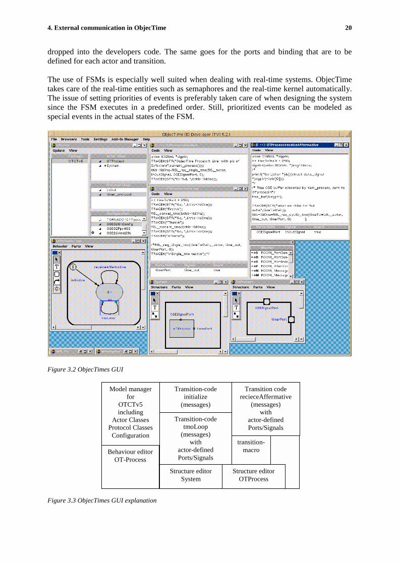
4. External communication in ObjecTime 20
dropped into the developers code. The same goes for the ports and binding that are to bedefined for each actor and transition.
The use of FSMs is especially well suited when dealing with real-time systems. ObjecTimetakes care of the real-time entities such as semaphores and the real-time kernel automatically.The issue of setting priorities of events is preferably taken care of when designing the systemsince the FSM executes in a predefined order. Still, prioritized events can be modeled asspecial events in the actual states of the FSM.
Figure 3.2 ObjecTimes GUI
Figure 3.3 ObjecTimes GUI explanation
Model managerfor
OTCTv5including
Actor ClassesProtocol Classes
Configuration
Transition-codeinitialize
(messages)
Transition-codetmoLoop
(messages)with
actor-definedPorts/Signals
Transition coderecieceAffermative
(messages)with
actor-definedPorts/Signals
transition-macroBehaviour editor
OT-Process
Structure editorSystem
Structure editorOTProcess
4. External communication in ObjecTime 21
ObjecTime is a set of tools that spans critical sections of the software development procedure.Currently, ObjecTime provides tools for capturing requirements as well as designing,executing, debugging, and documenting designs. The tools are all integrated within thedevelopment environment. The debugging tool is especially user-friendly. The possibility tocreate Message Sequence Charts (MSCs) in the Simulation Services Library makes debuggingeasy and convenient. (The debug environment is illustrated in Figure 4.3).
Besides what has been mentioned above Rational, the company that provides ObjecTime, alsosupplies aid for documenting the work done in a stylish way. Documenting changes anddevelopment is necessary when working in projects, if software units are to be reused orchanged by other team members. Rational also offers a version control tool, ClearCase. Thistool is used to label different progress steps, record and report actions, history and milestonesand assure integrity of software elements.
3.3 How to use ObjecTime?
When the design is done in UML, it is fairly simple to translate the design into an ObjecTimemodel. This is done via a ROOM translation as mentioned before. “Many, if not most, of thedesign errors in projects occur because the design was ambiguous or not properly translatedinto the software architecture and eventual code. ObjecTime eliminates these translation stepsby creating a methodology and a tool that let a team seamlessly move from high-level designall the way down to code, with no translation steps." [7] Until now ObjecTime has been basedmostly upon the ROOM notation, though in the coming version of ObjecTime (v 6.1) achange towards direct implementation of an UML (v 1.4) design will be carried out. This willnot result in any major changes in notation since the ROOM notation well corresponds to thedifferent components in an UML design.
To learn ObjecTime, working through a tutorial is recommended. This gives you a rapid, stillthorough, insight in the basic ObjecTime concepts.
A software unit in ObjecTime is composed of two main parts: [7]
• The generated files and directories that represent the ROOM/UML model. Thisincludes the structural components (actors, and so forth), as well as the behavioraldetail of the model (the C code for transition actions, choice points,...)
• The ObjecTime Run-Time Service (RTS), which provides an abstract interface to theunderlying OS services. The RTS provides the support for basic ROOM/UMLconcepts such as the message-based communication service. The generated codestructure of the user model includes the hooks into the underlying ROOM/UML RTS.
3.3.1 Run-Time Services (RTS)
The RTS is simply the simulation tool in ObjecTime Developer. It is possible to runObjecTime in two different versions of the RTS. The Simulation Services Library (SimulationRTS) and the C Target Services Library (C Target RTS) respectively. The Simulation RTScan be run on a variety of workstation-platforms while the C Target RTS runs on manyoperating systems and on workstations. It is also designed to be easily user-ported toadditional target environments. The Simulation RTS is inherently C++ based and uses a C++compiler to generate an executable, while the Target RTS is strictly C-based (in the C version

4. External communication in ObjecTime 22
of ObjecTime). C++ is used because of the close connection between the Service RTS and theObjecTime graphical toolset, which is C++, based.
The workflow that is recommended in taking a model from early prototyping to finalproduction is shown below. The first step enables a full use of the simulation tools anddebugging capabilities. The second step, which is reached after some necessary adjustments,is used to check the compilation. Here one can use C-source debuggers and C analysis tools tosecure that the model runs as wanted. The ObjecTime feature Target Observability is a well-suited tool for verification of the behavior of the model.
Figure 3.4 Workflow in ObjecTime
The final step is to compile the model for your platform and download and run the model onthe target. Of course there are no systems that can be verified without feedback, and thisprocess has to be run numerous of times with incremental improvements.
3.4 What does ObjecTime consist of?
3.4.1 Software Components
The software components in ObjecTime act as black boxes, similar to a Finite State Machine(FSM), against each other and have a protocol for interacting with other software components.This means that components can be reused in different models as long as the same interface isused.
Model X Model Y
Component A
Figure 3.5 Reusable software components
Changes in one component of a design can be localized, taken care of and fitted into theenvironment among other components as long as the same interface is preserved. Usingencapsulated components helps manage the complexity of a design, and increases the overallreliability of the software.
1.Start with C and
Simulation ServicesLibrary
2.Target Services
Library onWorkstation
3.Move to Target
Services Library onRTOS
A
A
AB
C D
MN

4. External communication in ObjecTime 23
3.4.2 Real-world and virtual models
When designing it is often convenient to model real-world entities as software components.They model concrete entities that exist in the application domain. ObjecTime allows designersto create components that correspond directly to things in the real-world application domainas well as virtual or abstract entities. Virtual or abstract entities might be such as an algorithmor data structure (for example a queue), or a piece of software that performs a special functionthat doesn't exist in real life. An example of a real-world entity is a telephone while a phone-call can be modeled as a virtual entity.
To simplify reuse and protection of software components are stored in libraries. This reducesthe overall effort required to develop new and maintain old software, and makes it easy towork in parallel in teams.
ObjecTime is made up of some corner stones. They define what can be done and how it isimplemented. Since the core in ObjecTime is UML/ROOM, which originally was developedas aids for object-oriented software development, the components are much similar to thedifferent parts of any object-oriented development language. (All entities named below,except data classes, are shown in Figure 3.2 as they appear in ObjecTime Developer.)
3.4.2.1 Actors
The basic structural components in ObjecTime are called actors and are the main units ofdesign. In UML/ROOM there are standards specified for how the definitions of actors aremade. This simplifies the reading of the generated code that ObjecTime evolves. A telephoneexample will be used to illustrate the different entities in ObjecTime. To start with an exampleof how actors form a model is shown.
Figure 3.6 Actors
Actors have some parts that are specific, and five points can be listed namely: [5]
• Actors are potentially concurrent.• Actors communicate by sending messages.• Actors are encapsulated.

4. External communication in ObjecTime 24
• Actors have a structure.• Actors can have a behavior.
In the telephone example the points above can be:
• When a phone is in use, one can not use it for other calls.• A handset actor communicates with the base unit actor.• The base unit does not see what states the handset actor contains and vice versa.• A telephone contains a handset, tone generator, keypad, hook-switch and base unit.• The actions that have to take place to process an outgoing call.
If ObjecTime is going to be used in an appropriate way, designing multi-layered systems ismandatory. With layers containing more than six states, where a state is an instance of anactor, it is fairly hard to get a clear overview of the system. The example in Appendix Acontains six actors in the first layer, with five of them containing subactors. This is indicatedby the small rectangles in the lower left corner of these actors.
3.4.2.2 Messages
The actors communicate and interact with each other by sending messages from ports viabindings to other ports on other actors or to subactors within it. Those bindings are edited inthe model manager and make the system easy to understand. For each actor you have todesignate a set of messages to which it will respond. A complete design represents an overallsystem, and each actor is a part of the system. The overall behavior of the system is the sumof the behavior of all its interacting components.
It is not possible for an actor in the system to look inside other actors. By encapsulation,actors are not directly aware of other actors in the design: they see only their own interfacethrough which they may communicate. Other actors send messages to request that an actorperform the functions for which it is responsible.
Message processing can be illustrated as the signaling between a keypad actor and a tonegenerator in the telephone example.
Figure 3.7 Messages
4. External communication in ObjecTime 25
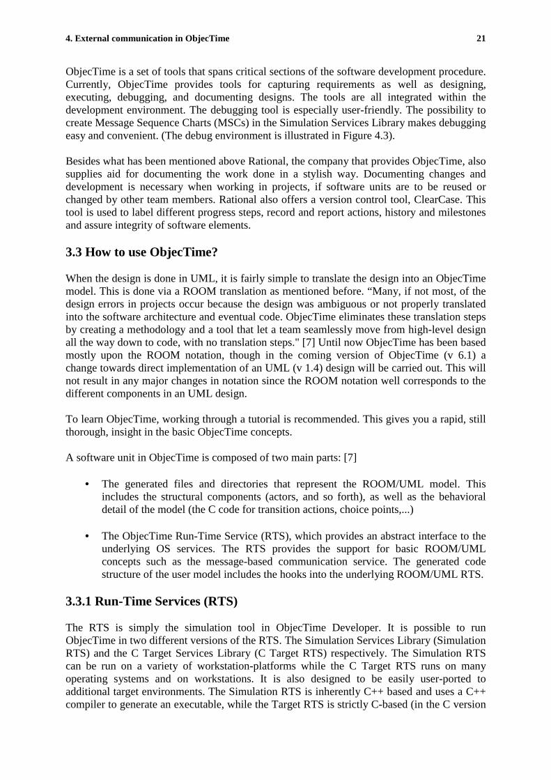
3.4.2.3 Actor Classes
Actor classes are the most basic component in an ObjecTime design. These specify thefundamentals for actors of a special type. All actors have a class specification witch serves asa skeleton for actors of the same type.
Two or more actors belonging to the same type used in a design are said to be references ofthe same actor class. Each actor class specifies the actor's structure and behavior, as well asthe messages it can send and receive. Classes can also be stored in a library where they can bereused in other designs.
To communicate in a telephone network one has to have at least two telephone references tothe telephone actor class.
Figure 3.8 Actor Classes
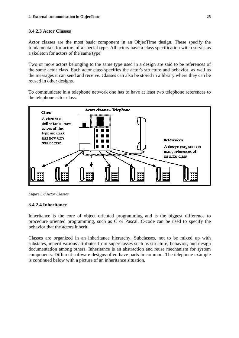
3.4.2.4 Inheritance
Inheritance is the core of object oriented programming and is the biggest difference toprocedure oriented programming, such as C or Pascal. C-code can be used to specify thebehavior that the actors inherit.
Classes are organized in an inheritance hierarchy. Subclasses, not to be mixed up withsubstates, inherit various attributes from superclasses such as structure, behavior, and designdocumentation among others. Inheritance is an abstraction and reuse mechanism for systemcomponents. Different software designs often have parts in common. The telephone exampleis continued below with a picture of an inheritance situation.

4. External communication in ObjecTime 26
Figure 3.9 Inheritance
Inheritance allows you to factor the common areas of a component into a superclass, and thensimply add specific behavior to subclasses that are specialized for the different designs.This has two benefits:
• A common design is reused, instead of being copied and modified, or even re-invented.
• When bugs are discovered in the design, a single change fixes all affected designs.This makes software more reliable in the long run.
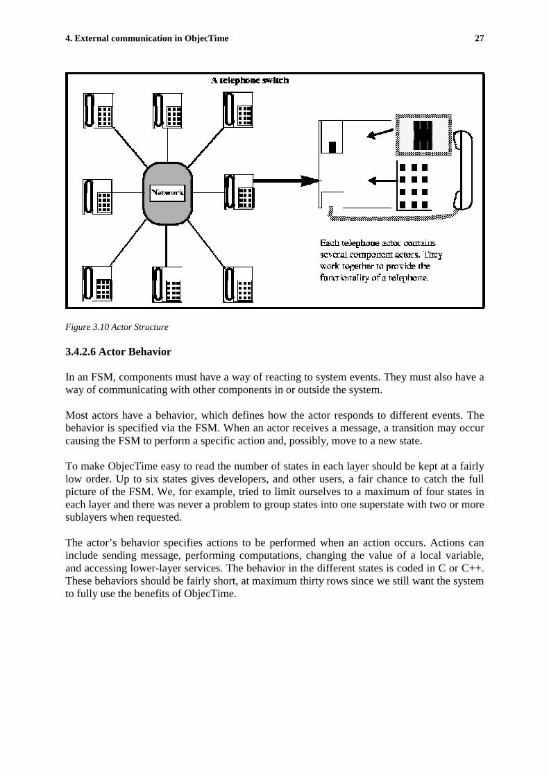
3.4.2.5 Actor Structure
To keep the complexity of software at an as low level as possible it is strongly recommendedthat you try to simplify your design. Actor structure is preferably organized in a mannerwhere actor classes contain references to other actor classes.
This is a way of simplifying designs by allowing complex actors to be decomposed intosimpler actors. Decomposition is an important principle in ObjecTime. It is a very useful wayof dealing with software complexity. The decomposition is described by an actor’s structure.Structure is defined in the actor's class specification. The structure captures thecommunication and containment relationship among system components.
The actor structure is illustrated and further explained in Figure 3.9.
4. External communication in ObjecTime 27
Figure 3.10 Actor Structure
3.4.2.6 Actor Behavior
In an FSM, components must have a way of reacting to system events. They must also have away of communicating with other components in or outside the system.
Most actors have a behavior, which defines how the actor responds to different events. Thebehavior is specified via the FSM. When an actor receives a message, a transition may occurcausing the FSM to perform a specific action and, possibly, move to a new state.
To make ObjecTime easy to read the number of states in each layer should be kept at a fairlylow order. Up to six states gives developers, and other users, a fair chance to catch the fullpicture of the FSM. We, for example, tried to limit ourselves to a maximum of four states ineach layer and there was never a problem to group states into one superstate with two or moresublayers when requested.
The actor’s behavior specifies actions to be performed when an action occurs. Actions caninclude sending message, performing computations, changing the value of a local variable,and accessing lower-layer services. The behavior in the different states is coded in C or C++.These behaviors should be fairly short, at maximum thirty rows since we still want the systemto fully use the benefits of ObjecTime.

4. External communication in ObjecTime 28
As described below an outgoing call demands, at a high level, at least a pickup of the handset,dialing a number, placing the call and a hang-up.
Figure 3.11 Actor behavior
3.4.2.7 Ports and Bindings
The interaction between actors is managed through ports and bindings. A port is a reference toa protocol class which defines the set of messages that a port is permitted to send and receive.The binding is a connection between the ports that channels the communication or interaction.Ports are attached externally to the interface of an actor or internally for communicationwithin the actor. A binding has to be placed between the keypad actor and the tone generator.The ports, in this example, are only permitted to send respectively receive digits.
Figure 3.12 Ports and Bindings
4. External communication in ObjecTime 29
3.4.2.8 Data Objects
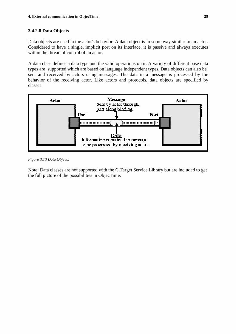
Data objects are used in the actor's behavior. A data object is in some way similar to an actor.Considered to have a single, implicit port on its interface, it is passive and always executeswithin the thread of control of an actor.
A data class defines a data type and the valid operations on it. A variety of different base datatypes are supported which are based on language independent types. Data objects can also besent and received by actors using messages. The data in a message is processed by thebehavior of the receiving actor. Like actors and protocols, data objects are specified byclasses.
Figure 3.13 Data Objects
Note: Data classes are not supported with the C Target Service Library but are included to getthe full picture of the possibilities in ObjecTime.

4. External communication in ObjecTime 30
4. External communication in ObjecTime
4.1 Making ObjecTime communicate with external systems.
To meet the main objective of these thesis which, i.e. to enable external execution of existingreal-time functions (a package called MPS at Ericsson Radio Systems, developed in theRTOS OSE-delta at ENEA) from within ObjecTime, part objectives were established. Thosewere first to manage the communication with test programs running on a simulator, PLS-Sim(HOST-testing), and then implement our solution, with code-generation, on a target processorAMD (TARGET-testing), as Figure 4.1 illustrates. As the next generation of radio-bases willbe developed on PowerPCs, there was a possibility to implement our solution on a newPowerPC as well. This would have been very similar to the AMD-case, but as we reached thispoint the department's progress in developing an environment for the PowerPC wasn'tcompletely finalized.
C was the main developing language at our department. This because C is a fairly low-levellanguage, close to assembler-code. The C version of ObjecTime doesn’t include all thefunctionality that the C++ version does. One drawback of using the C version is that atsimulation C-models are actually transformed into C++ executables running on top of aSimulation Services library. This is though, for most parts, invisible to users running modelsin the Simulation Services Library, but could be seen as a simulation of C++ code and not Cas intended. The different MPS-functions are written in C on an OSE-delta platform.
OSE-delta is a real-time operating platform developed at ENEA. Our aim was to develop aninterface in ObjecTime that managed the communication with HOST/TARGET so that theMPS-functions could be viewed as being actors within the ObjecTime model. ObjecTime waschosen because the UML-core and the possibility to evaluate the system through TargetObservability. To accomplish our task a number of obstacles had to be solved.
Figure 4.1 System parts and relations
Function callsObjecTime(C-version)
based on the UML-design.
MPSfunction-library.
based on theOSE-delta RT OS
Simulation RTS(Workstation)
ObjecTime testing.
Target RTS(AMD/PPC)
Target RTS(Workstation)
Pls-Sim testing.
321
4. External communication in ObjecTime 31
4.1.1 Communication
To choose, and choose wisely, how to manage the communication to and from ObjecTime welooked at some different aspects beside the sole RT-aspect. Four major areas were discussed.
1. Compilation2. Synchronization of processes (hunting)3. Addressing (linking) and4. Initiation.
4.1.1.1 Compilation
To be able to use the MPS functions, they had to be included in ObjecTime. Our aim was tounify the compilation and MPS function inclusion process. This was at first done inObjecTime through writing the full function path in the configuration manager (can be seen inFigures 3.2 and 3.3) as inclusions for each ObjecTime-system. Since there often are up totwenty different functions that needs to be included and those search paths contain manylayers we grouped all the functions needed in an archive including the MPS functions. Thisarchive was stored in the ClearCase environment and included into ObjecTime as one linkonly. Still we had to make an extra compilation of the archive.
The link-solution was improved as the thesis progressed and now we have entirely skippedthe archive for the MPS functions. Even the external compilation can now be skipped. Thiswas one objective for choosing the way of "function implementation" that we did. Thedifferent "function implementation" alternatives will be evaluated below.
We would also like to do just one compilation of the entire system (ObjecTime, theHOST/TARGET program(s) and the external functions). Since it takes some time to compileObjecTime as well as the external units we would like to see that parts of the compilation isoptional, so that time is not wasted on compilation of already compiled processes. Thecompilation can be implemented in the ObjecTime make file, by making a load pearl script,ld.pl, file that "overrides" the old linking.
4.1.1.2 Synchronization of ObjecTime and MPS processes
Problems can occur with the priority of the processes as well as the with the port addresses,i.e. ObjecTime doesn't know what address to send and receive signals on. This can be adilemma when we want the processes to automatically initiate the communication betweeneach other. We had to solve this problem, with the processes starting in a proper order. As afirst naive solution we wrote a macro in an init transition in ObjecTime that used a "while-loop" to wait for the external initialization-process to start. When started this process sent amessage with it's priority and address to ObjecTime indicating that it now was all right forObjecTime to start running. This solution was time-consuming and looked bad for a real-timesolution. Finally, with some assistance from Tom Moore at Rational, a compilation pearlscript was created that initiated the synchronization and set ObjecTime in it's first ready state,waiting for the external process or an event (internal or external) to occur firing a transition.Priority and address were stored in a linked list as mentioned below.

4. External communication in ObjecTime 32
4.1.1.3 Addressing
Since we were using processes running at different platforms, it happened to be that theaddresses for ObjecTime and MPS had different sizes. Incoming messages from MPS to werenot recognized in ObjecTime and vice versa. This problem was solved with two new queuesthat was created in ObjecTime, one for incoming messages and one for outgoing messages.The queues, two linked lists, inserted the function-calls in priority-order and modified theadresses to fit the recievers standard. Linked lists are by far the least time-consuming andflexible way of keeping track of those lists.
4.1.1.4 Initiation
OSE-delta's and ObjecTime's default installations, had to be examined. As we have seenabove, problems can occur if they have different default port-addresses, address-size etc. Thesolution was to write a batch-file for ObjecTime that initiated the receive-/send-queues,managed the compilation, and set the standards for those ports and address sizes. The filestarts the HOST/TEST compilation, executes it, when done starts ObjecTime, makes acompilation of ObjecTime from within and finally closes it down.
4.1.2 Function implementation
Run-Time service systems can be equated to the so-called "system" services of traditionaloperating systems. For example, inter-process communication, file system access, or runtimeexception handling are standard services provided by most operating systems. In ObjecTimesuch facilities are folded into the more general concepts of layering and services.
Layering handles the communication with other processes as well as internal communicationwhile services takes care of function calls and the different operations executed during run-time (internally) [5]. In the "function implementation" phase the major issue was to ensure asound real-time solution. The telecommunication area is an area that mostly runs under hardreal-time constraints. Therefore we chose to implement every function as if it had to meet thehardest time constraints. This made this to be the largest problem to be solved. We had toinvestigate, test, implement and verify the different ways of solving the communication andfunction implementation of MPS functions into ObjecTime. Several alternatives were foundpossible. Some of them were fairly rapidly rejected while others were found to be almost asappropriate as our final solution. The different alternatives were as follow.
4.1.2.1 Proxy
This is a simple communication method to implement. It is also a reasonably effectivesolution when there are no hard real-time restrictions to meet. Experts at Rational told us thatthis method was the most widely used way of dealing with the external communication. Thetime-aspect is difficult to fulfil because of the proxy, which acts as a bounce-point, thatreceives the signal, manages it and finally forwards it.

4. External communication in ObjecTime 33
Figure 4.2 Proxy Solution
Since telecommunication features extremely hard real-time objectives this solution couldn't beused but are recommended for applications with soft time-constraints.
To implement the proxy-solution one has to create a signal-processing actor class, proxy, andthen specify an instance of this class for each function call inside ObjecTime. In Figure 4.2the EventHandler uses six instances of function calls that can be sent and handeled via sixdifferent proxies. The proxy communicates, with its MPS function, in the OSE-deltaenvironment. The signals are sent to and from ObjecTime/OSE-delta via the proxy where theyare modified to fit the receivers signal structure. This solution can be seen as two black boxescommunicating with each other, with no possibility for Target Observability, that is, it is notpossible for ObjecTime to see what signals that are sent in the OSE-delta environment andvice versa. Target Observability will be described in detail below. The debugging ca not bedone in ObjecTime in any other way than with "printf". The Target Observability problemwill be solved in the new version of ObjecTime (6.1).
4.1.2.2 SAP/SPP
Service Access Point/ Service Provision Point can be seen as ports that send messagesthrough different layers instead of ordinary ports that send within specific layers. TheSAP's/SPP's are not graphically represented in the model as ordinary ports are. This solutionmight look as the natural communication alternative at a glance. ObjecTime appears as onelayer and the external layer as an other. It is also the method recommended in the ObjecTimemanual, but when evaluated it appears to be both complicated to implement, and fairly time-consuming to run. ObjecTime functions are used, but it is the adress string for these functionsthat has to be sent to OSE. In every call from ObjecTime through SAP/SPA, ObjecTime hasto search for an address string in a fairly huge address register. If we have many calls/secseeking for addresses, the solution becomes even more time consuming than the "proxy"solution.

4. External communication in ObjecTime 34
4.1.2.3 Inline coding
This is the straightforward "low-level" programming solution. One simply recodes all MPS-functions into replicas in ObjecTime. This is of course a very time-consuming method anddemands a great deal of work. Every function has to be exactly imitated and with a fairlysmall insight in the different functions besides the amount of functions to be rewritten this isan alternative that is hard to implement.
4.1.2.4 Port send (unbound)
This alternative looked almost similar to the SAP/SPP solution, with the drawback of findingthe function adresses The difference is that the developer defines what the signal shouldcontain, and that this solution is unbound. Unbound indicates that there are no threads drawnbetween ObjecTime and the external system. Instead port send uses a signal register whensending and receiving signals. Still ports are modeled in ObjecTime but there are no bindingsconnected to them. For example it might look as follows in a port that sends and recievesmessages (from an ObjecTime point of view):
Incoming Register (Signal, Port, OTSignal, Actor)Outgoing Register (OTSignal, Actor, SignalNo, Size, Address)
The hardest thing to manage is what size and address the outgoing register is supposed to use.The size of the signal might have different physical size in OSE-delta and ObjecTime and itappeared that OSE-delta and ObjecTime did not use the same format for similar definitions.(32 respectively 16 bytes for unsigned char). As this problem was harder to solve than firstexpected we did not continue on this track although it looked quite promising.
4.1.2.5 Function call
The most flexible solution, which this chapter will focus on is the function call solution. Allcommunication to OSE-delta is wrapped up as function calls. In these project the functionnames in MPS was used, since the developers at Ericsson are familiar with those. To ensurethat trere are no possibilities for mix up RSL was added before the MPS call, i.e.“req_single_tmo” in MPS is referenced to as “RSL_req_single_tmo” The signals are sent outand received on an unbound port in ObjecTime. In the “RSL_...” definitions the MPSfunctions has to be called and the recieving, or sending, actors as well as ports and signals inObjecTime has to be determined. At compilation ObjecTime will give an error messagebecause it can not find a recipient. As a first solution we simply specified the external target(HOST or TARGET) the first thing at run time and wrote a macro to initialize thecommunication in the initialization file in ObjecTime. The final solution was to modify themake-files in ObjecTime. Now the error messages are not showed anymore and thecommunication initialization is performed automatically at compilation. An other problemwith this solution is that one must know what actor and which port on that actual actor youwant to send your signals to. The only ways to manage this is either to always know whatactor and port adress you are sending to, which is most often solved with having one specificcommunication port, or to look for the address number in an Object database. Finally theaddressing problem is solved in an elegant way where one specifies the port with name andactor and then ObjecTime finds the address number in the Object database automatically. Ifthe signal is to be sent to the same port as it was sent from an &-pointer can be used forconvenience.
4. External communication in ObjecTime 35
This solution is more complicated to implement than the Proxy solution. Since the functionsare called from ObjecTime in the same manner as it would have been in any other process thefunctions do not need to be included in any archive. Function calling is far more effective thanmost of the other alternatives when the call is time dependent, as for timer-functions calls. Another necessity is that ObjecTime uses the same timer as OSE-delta does, and this wasachieved in this solution as well.
4.2 Target Observability
One of the major reasons for using ObjecTime as UML tool is that it features a Simulationtool that enables Target Observability. This tools enables debugging functions such as state-machine animation and break points, message tracing, message inclusions, single steppingand MSC plotting. [12] As to date PLS-Sim has been used for simulating the SW models.
During the progress of this thesis ENEA developed a new version if OSE-delta. This versionbetter supported Target Observability. The problem had been that a function had been usedwith the same name in OSE-delta as in ObjecTime. With this feature one are able to see whatsignals are sent, when they are sent and from and to what ports the signaling occurs.This is seen in the RTS control panel as in Figure 4.3.
As to date developers are able to plot Master Sequence Charts (MSC, exemplified in Figure4.3 below), when running the model on a HOST target, to get a clear view of the Finite StateMachine (FSM) signaling inside ObjecTime, but not for actors or procedures acting fromoutside ObjecTime. MSC’s are great to use when pinpointing race conditions that haveoccurred because of flaws in the design process or alternative execution scenarios.

4. External communication in ObjecTime 36
Figure 4.3 ObjecTime Views
In forthcoming versions of ObjecTime you should be able to automatically create FSMs fromyour MSC.
Problems can occur when porting ObjecTime to the target since one has to specify thephysical port number (master port) for the communication. To date you are only able to usethe Target Observability feature for simulated processes. Your system can be tested andverified, but still you can not use this nice feature on your target platform if you run the Cversion of ObjecTime. In the C++ version this is solved and in version 6.1 of ObjecTime thiswill be implemented in the C version as well.

4. External communication in ObjecTime 37
4.3 Results
This thesis resulted in a model, illustrated in Figure 3.2 and 3.3, which can be run on an AMDTarget. The model runs, is developed and can be evaluated in an ObjecTime environment.After the necessary start-up procedure a ”Request Single Time Out” is requested in theinitialize-transition from the MPS function library. MPS returns a call when the time-out hasrun out. This triggers the recieceAffermative transition and the ”Request Single Time Out” isfollowed by a ”Request Cyclic Time Out”. One time-out is executed and afterwards theObjecTime model triggers the tmoLoop. Here it signals ”Cancel Time Out” with simple callthat includes the time out identity. In this transition the multiple time out is restarted as well.The function calls are described in detail below. This banal model runs on the Targetprocessor and dumps a “printf” each time a signal is received from the OSE-deltaenvironment.
In ObjecTime we had to implement a function call interface to the MPS functions that was tobe used. This interface can be used as a template for further function implementations.
As the ObjecTime model runs smoothly on Target as well as in Simulation the probability fora full implementation of UML-design using ObjecTime (v 6.1, Rational Rose-RT) hashopefully increased.
As mentioned above four MPS time-out functions were implemented in ObjecTime, namely:RSL_req_single_tmo, RSL_req_cyclic_tmo, RSL_cancel_tmo and RSL_restart_tmo.
The function-calls looks like:
• RSL_req_single_tmo (int timeOutValue, RSLActorIndex _actor, RSLSignalIndex _signalRSLPortIndex _port, void* _data);
• RSL_req_cyclic_tmo (int timeOutvalue, RSLActorIndex _actor, RSLSignalIndex _signal,RSLPortIndex _port, void* _data);
• RSL_req_cyclic_tmo (mpsk_tmo_id *timeOutId);
• RSL_restart_tmo (mpsk_tmo_id *timeOutId);
Here ”timeOutValue” is the length of the time-out in milliseconds, ”_actor”, ”_signal” and”_port” are the adress, signal and port to witch the time_out call shall send it’s respond,”_data” is an extra void-pointer for future undefined purposes and ”*timeOutId” is a pointerto the actual timeout.
A header-file containing the definitions of the MPS-inclusions is stored in the ObjecTime-file: …/objectime/TargetRTS/include/ crsl_if.h. This header-file is target-independent, that isit goes for every instance of OSE-platform (HOST, AMD and PPC).
The function-calls are specified in a *.c file in ObjecTime. Here it is necessary to rewrite andstore the *.c files locally for every OSE-target. The name of this file is RTThrSig.c and it isstored in …/objectime/TargetRTS/src/target/OSEXX/CRSL/. XX is the OSE-target andequals: 32SK for HOST, 26 for AMD respectively 32 for PPC. (SK stands for Soft Kernal).

4. External communication in ObjecTime 38
Problems can occur when compiling ObjecTime if the pathes to the external root-libraries notare specified. It is recommended that at least the OSE, PLS and MPS root-pathes are definedin the …/objectime/TargetRTS/target/OSEXX/target.mk file specific for every OSE-target.
To verify the functionallity of the time-out function calls a small ObjecTime program wasdeveloped. It contained three transitions, as seen in Figure 3.2.
The first transition, initialize, calls a ”RSL_req_single_tmo” in 50 milliseconds. The pointer,”this->idOne”, stores the timeout id. Figure 3.2 shows that the ”RSL_req_single_tmo”responds to the same actor as from it was sent. It sends a ”InOutSignal” on port”OSESignalPort”. In the bottom of the transition code editor of the ”recieceAffermative” (!) itis indicated that this transition is triggered by a ”InOutSignal” on port ”OSESignalPort”. Asthis is received the ”recieveAffermative” transiton is fired. Now a ”RSL_req_cyclic_tmo” callis done in the same manner as described in the ”RSL_req_single_tmo” case. The respondfrom this call triggers the third transition, ”tmoLoop”. In this transition ”RSL_cancel_tmo”cancels the ”RSL_req_cyclic_tmo” and the ”RSL_restart_tmo” call restarts it again.
(The TRACEH calls are OSE calls aswell, and are used for debugging purposes.)
To think of, when developing in the ObjecTime/OSE environment, is that compiling has to bedone in two, or optionally three, steps. First the ObjecTime TargetRTS environment has to becompiled. This is done in …/objectime/TargetRTS/src> with:
clearmake CONFIG=OSE32SKT.sparc-gnu-2.8.1 (HOST)clearmake CONFIG=OSE26T.amd29k-gcc-2.5.2-921031 (AMD)clearmake CONFIG=OSE32T.ppc403-Diab-4.0b.3 (PPC)
Here gnu, gcc and Diab are the compilers used for each TargetRTS.
If a SU is developed and stored in ClearCase this can be compiled seperately or togheter withthe ObjecTime SU. If choosen to be compiled togheter one has to choose which SU to becompiled first. The easiest way is to make a patch in the mk.rules files for the ClearCase SUthat starts the ObjecTime compilation. To do the other way around one has to make the patchin the ObjecTime-generated ld.pl file (pearl-script).
Two library inclusions have to be made in ObjecTime Developer configuration is now thefollowing directories: …/pls2/pls_sw/ MPS/MPSK/EXPORT
and EXPORT
Besides the functions stdio.h, stdlib.h, string.h, mpsk_timeout.h, mpsk_traceh.h inclusionsthat includes MPS functionallity.
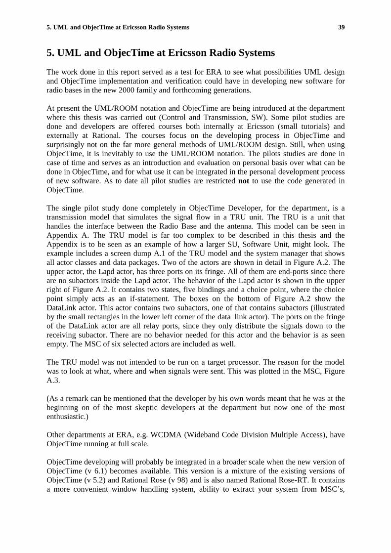
5. UML and ObjecTime at Ericsson Radio Systems 39
5. UML and ObjecTime at Ericsson Radio Systems
The work done in this report served as a test for ERA to see what possibilities UML designand ObjecTime implementation and verification could have in developing new software forradio bases in the new 2000 family and forthcoming generations.
At present the UML/ROOM notation and ObjecTime are being introduced at the departmentwhere this thesis was carried out (Control and Transmission, SW). Some pilot studies aredone and developers are offered courses both internally at Ericsson (small tutorials) andexternally at Rational. The courses focus on the developing process in ObjecTime andsurprisingly not on the far more general methods of UML/ROOM design. Still, when usingObjecTime, it is inevitably to use the UML/ROOM notation. The pilots studies are done incase of time and serves as an introduction and evaluation on personal basis over what can bedone in ObjecTime, and for what use it can be integrated in the personal development processof new software. As to date all pilot studies are restricted not to use the code generated inObjecTime.
The single pilot study done completely in ObjecTime Developer, for the department, is atransmission model that simulates the signal flow in a TRU unit. The TRU is a unit thathandles the interface between the Radio Base and the antenna. This model can be seen inAppendix A. The TRU model is far too complex to be described in this thesis and theAppendix is to be seen as an example of how a larger SU, Software Unit, might look. Theexample includes a screen dump A.1 of the TRU model and the system manager that showsall actor classes and data packages. Two of the actors are shown in detail in Figure A.2. Theupper actor, the Lapd actor, has three ports on its fringe. All of them are end-ports since thereare no subactors inside the Lapd actor. The behavior of the Lapd actor is shown in the upperright of Figure A.2. It contains two states, five bindings and a choice point, where the choicepoint simply acts as an if-statement. The boxes on the bottom of Figure A.2 show theDataLink actor. This actor contains two subactors, one of that contains subactors (illustratedby the small rectangles in the lower left corner of the data_link actor). The ports on the fringeof the DataLink actor are all relay ports, since they only distribute the signals down to thereceiving subactor. There are no behavior needed for this actor and the behavior is as seenempty. The MSC of six selected actors are included as well.
The TRU model was not intended to be run on a target processor. The reason for the modelwas to look at what, where and when signals were sent. This was plotted in the MSC, FigureA.3.
(As a remark can be mentioned that the developer by his own words meant that he was at thebeginning on of the most skeptic developers at the department but now one of the mostenthusiastic.)
Other departments at ERA, e.g. WCDMA (Wideband Code Division Multiple Access), haveObjecTime running at full scale.
ObjecTime developing will probably be integrated in a broader scale when the new version ofObjecTime (v 6.1) becomes available. This version is a mixture of the existing versions ofObjecTime (v 5.2) and Rational Rose (v 98) and is also named Rational Rose-RT. It containsa more convenient window handling system, ability to extract your system from MSC’s,

5. UML and ObjecTime at Ericsson Radio Systems 40
better documentation tools etc. Ericsson holds a license of Rational new products and freesupport can be used and received continuously.
6. Summary 41
6. Summary
The object of this thesis is to describe UML-RT and evaluate to what degree UML-RT baseddesign, verification and implementation (with ObjecTime) can be implemented into theexisting development process at Ericsson Radio System. ObjecTime was chosen because ofrecommendations from a previous thesis. Ericsson Radio has previously used non-graphicalmethods during the testing, implementing and verification of Radio Base Stations. The newgraphical programming languages has integrated the design and development process, makingit possible to develop the system more accurate from the initial design, Ericsson Radio isinterested in applying ObjecTime to the software development of Radio Bases. This thesiswill describe both UML-RT and how ObjecTime could be integrated with the development ofRadio Base systems.
We found that when integrating two different systems with each other, problems in the fringesbetween, in this example, ObjecTime and MPS were common, i.e. during compilation or inspecial cases when a certain kind of information is sent from one system to the other. In thisparticular case problems during compilation appeared due to overlapping names on differentprocess calls, and information was interpreted wrong because the two systems used differentstandards on dataclasses. This was solved with changes in a pearl script and with changeswith help from ENEA, the developer of OSE delta real-time OS. What may be annoying forthe developer is that one still has to include, by hand, several functions from the olddevelopment tool, MPS, this means that when files are moved or renamed in MPS, changesalso has to be done in ObjecTime. A future goal of the implementation will be to make MPSand ObjecTime independent from each other, with out destroying the compatibility of the twoprograms. The advantage of the current implementation, is that other systems may easily beconnected with each other by using the same solution that we have developed. Even thecommon compilation that we implemented can be extended to include other systems that needto be compiled.
There are some minor disadvantages with the C-version of ObjecTime. One is that dynamicstructures are not supported. This is an obstacle when adding new hardware components thatmust be represented as new actors in the software. Another problem is that inexperiencedusers easily tend to spread out small chunks of C-code on different places, such as intransitions, enter- and exit-code for states. This makes the generated code somewhat messy.
We conclude that UML-RT has strengths for developing real-time systems. Mostly because ofthe use of a uniform notation throughout the entire development process, from a designprocess that easily is translated into an executable model in ObjecTime where the codegeneration is done. The use of a standard, visual design process that is transformed directlyinto code means that the source code easily can be read, understood, reused and changed.
Since the UML-RT notation is based on independent components it is fairly easy to createdifferent instances of the same component and then try the different alternatives to find anoptimal solution.
The possible extensions that can be performed in the coming version of ObjecTime 6.1 are:
Include Target Visibility on the Target Platform, which as to date only can be done whensimulating the system on your workstation.
6. Summary 42
The possibility to look into external systems to see what and when signals are sent. Thismakes it possible to draw Message Sequence Charts for the entire system and not only for thepart implemented in ObjecTime.
Implementing our solution on the PPC target. This requires little work as we already has donea solution that can be run on an AMD target.
Other extensions are:
Making compilation optional. As it is now, the entire system is recompiled when changes aremade. As to date one is able to compile separately but the different compilations have to bedone in different libraries, which are nestled down deep in the library system.

References 43
References
[1] Overcoming the crisis in real-time software development. Technical report,ObjecTime Limited, 1997. www.rational.com.
[2] UML notation guide. Technical report, Rational software Corporation, 1997.
[3] Paul Harmon. UML, object modeling, and requirements specification. CutterConsortium, 1999. www.cutter.com.
[4] UML summary, Technical report, ObjecTime Limited, 1997. www.rational.com
[5] ObjecTime Developer User Guide 5.2. ObjecTime Limited, 1998.www.objectime.com.
[6] Mike Bienvenu. Systems Design in ObjecTime. Technical report, Sparta Inc.,1995.
[7] ObjecTime Developer C Language Guide 5.2. ObjecTime Limited, 1998.www.objectime.com.
[8] Christian Demmer. Unified Modeling Language vs. MWOOD-I. Technicalreport, 1997.
[9] Bran Selic ObjecTime Limited, Jim Rumbaugh Rational Software Corporation.Using UML for Modeling Complex Real-Time Systems. Technical report, 1998.
[10] Bruce, Powel, Douglas. Real Time UML, Addison-Wesley, 1998.
[11] Garth Gullekson, Bran Selic, Paul T Ward. Real-Time Object OrientedModeling, John Wiley and Sons. 1994.
[12] Andrew Lyons, Developing and debugging Real-Time Software with ObjecTimeDeveloper. Real-Time Magazine 99-1.

Appendix A 44
Appendix A
figure A 1 TRU model
figure A 2 Example of Actors and their Behaviuor in the TRU model

Appendix A 45
figure A 3 MSC of selected actors of the TRU model