design guide for metal roofing and cladding
TRANSCRIPT
8/11/2019 Design Guide for Metal Roofing and Cladding
http://slidepdf.com/reader/full/design-guide-for-metal-roofing-and-cladding 1/36
THE METAL CLADDING
& ROOFING MANUFACTURERS
ASSOCIATION LIMITED
DESIGN GUIDE FOR METAL ROOFING ANDCLADDING TO COMPLY WITH ENERGYREQUIREMENTS OF UK BUILDINGREGULATIONS (2006)
CI/SfB
Rh2(4-)
FEBRUARY 2007
MCRMA/EPIC Technical Paper No. 17
F I R S T E D I T I O N

8/11/2019 Design Guide for Metal Roofing and Cladding
http://slidepdf.com/reader/full/design-guide-for-metal-roofing-and-cladding 2/36
Contents
Page Foreword 1
1.0 Introduction 1
2.0 Insulation - U-values 3
3.0 Thermal mass - Cm values 4
4.0 Thermal bridging - values 5
5.0 Condensation risk - f values 6
6.0 Air permeability 6
7.0 Junction details - introduction 7
8.0 Junction details – built-up metal cladding 7
9.0 Junction details – insulated metal panels 18
10.0 Checklist for recommended data entry 29
11.0 Case study – portal frame metal clad building 30
APPENDIX A Method of calculating U value for metal cladding 32
APPENDIX B Method of calculating value for metal junctions 32
APPENDIX C Reference Documents 33
© The Metal Cladding & Roofing Manufacturers Association Limited and Engineered Panels i n Construction Limited. February 2007

8/11/2019 Design Guide for Metal Roofing and Cladding
http://slidepdf.com/reader/full/design-guide-for-metal-roofing-and-cladding 3/36
1
Foreword
The European Energy Performance of BuildingsDirective (EPBD) requires member states from
January 2006 to establish methods of assessing
the energy use of buildings. The Building
Regulations for England and Wales, Northern
Ireland and Scotland are being amended to use a
new calculation tool – Simplified Building Energy
Method (SBEM) to comply with the directive.
The traditional method of compliance based on
limiting U-values for the various building elements
with allowance for thermal bridging can no longer
be used and is superseded by the whole building
method introduced in the new regional Building
Regulations.
The new method to demonstrate compliance
requires the use of the National Calculation
Methodology (NCM) for determining the energy use
of the whole building, including the building fabric,
lighting, heating, ventilation and cooling system.
The NCM uses the SAP rating system for dwellings
and residential property and SBEM for buildings
other than dwellings. This document does not
consider the requirements of the SAP rating system.
This MCRMA/EPIC publication illustrates how -
• Good design of metal clad buildings with roofs
of 0.25 W/m2 K U-value and walls of 0.35 W/m2
K (0.30 in Scotland) U-value, together with an
air permeability no greater than 10 m3 /(h.m2)
can achieve compliance with the required 2006
level of CO2 emissions.
• Major savings on CO2 emissions can be achieved
by improvements to the controlled services
including lighting, heating and, if installed, air
conditioning; these savings typically exceed three
times those available by changes to the building
fabric of metal clad portal frame buildings.
• Good detailing and workmanship on as-built
building is essential to achieve compliance. The
changes have introduced, for the first time in
the UK, checks on services and workmanship
at completion and a requirement to verify
the as-built performance against the original
design concept. This new methodology needs
to be understood and explained to the whole
construction team. A cheaper component is
no longer acceptable unless it has equal or
better performance than the original design
requirements.
This publication illustrates both basic design
details for insulated metal cladding constructions
This publication has been produced as a guide togood practice and construction for use of metal roof
and wall cladding to comply with the following parts
of the revised Building Regulations – Conservation
of Energy
For buildings other than dwellings
• Part AD-L2 :2006 England & Wales
• Part F :2006 Northern Ireland
• Section 6 :2007 Scotland
Guidance is provided for typical profiled metal
twin skin and insulated panel systems to aid
compliance with the relevant parts of the national
calculation methodology used by the above building
regulations. The freely available iSBEM (interface
for Simplified Building Energy Model) v1.2.a has
been used for the examples.
This joint publication has been prepared by
The Metal Cladding & Roofing Manufacturers
Association Limited (MCRMA) and Engineered
Panels in Construction Limited (EPIC) for guidance
in the design and use of profiled metal roof and
wall cladding.
MCRMA Technical Paper 14 (January 2002) is
quoted as a reference document in the AD-L22006 for England and Wales and Technical Booklet
F for Northern Ireland. This guide updates the
sections of MCRMA Technical Paper 14 with
new information on the recommended metal
cladding junction details and provides guidance on
entering metal cladding systems into the National
Calculation Methodology.
1.0 Introduction

8/11/2019 Design Guide for Metal Roofing and Cladding
http://slidepdf.com/reader/full/design-guide-for-metal-roofing-and-cladding 4/36
Approved Document L2A 2006 edition,Conservation of fuel and power in new buildings
other than dwellings of Building Regulations
England and Wales states:-
Building fabric
67 The building fabric should be constructed to a
reasonable quality so that:
a. The insulation is reasonably continuous over the
whole building envelope; and
b. the air permeability is within reasonable limits.
Continuity of insulation
68 The building fabric should be constructed so
that there is no reasonably avoidable thermal
bridges in the insulation layers caused by gaps
within various elements, at joints between
elements and at edges of elements such as
those around window and door openings.
69 Reasonable provision would be to:
a. Adopt design details such as
ii. For cladding systems, to adopt the guidance
given in the MCRMA Technical Note; or
b. to demonstrate that the specified details deliver
an equivalent level of performance using the
guidance in BRE IP 01/06.
This publication illustrates the design of insulated
metal cladding constructions to achieve the default
values given in Table 4 of BRE IP 01/06. These
same default values are available from the menu
for junctions including metal cladding in iSBEM.
The Building (Scotland) Regulations Section 6 does
not quote either BRE IP 01/06 or any MCRMA
Technical Paper as reference documents. However,calculation using BRE iSBEM is an approved
method of demonstrating compliance in Scotland
and will involve the use of some junction values
for metal cladding.
Members of EPIC and MCRMA should be able to
provide improved designs with values calculated
or tested to the approved methods, for use in
SBEM calculations to demonstrate compliance
with the regional variations of the UK Building
Regulations. Guidance is given in this document
where particular junction details may be improved
to significantly reduce the energy loss to aid withcompliance.
to achieve the default air tightness and limits forthermal bridging ( values) given in table 4 of BRE
IP 01/06 and also alternative recommended details
to achieve improved values. The recommended
design details and default values are made
available to assist the designer, manufacturer
and installers of metal roof and wall cladding on
buildings other than dwellings, to achieve levels of
best practice for the following critical factors:
• U-value of the external fabric
• Minimise energy loss due to thermal
bridging ( values)
• Minimise energy loss due to air permeability
through the building envelope
• Minimise the risk of surface condensation
Compliance with the above factors is considered in
relation to the energy use associated with natural
and artificial lighting, heating, forced ventilation and
cooling. References are provided to other guidance
documents intended to aid compliance and the use
of renewable energy sources.
Compliance using the iSBEM method can be
demonstrated by meeting five separate criteria as
follows:
Criterion 1: The predicted rate of carbon
dioxide emissions from the
building (BER) is not greater than
the target rate (TER) as defined in
the Building Regulation.
Criterion 2: The performance of the building
fabric and the heating, hot water
and fixed lighting systems are no
worse than the design limits set
out in the Building Regulation.
Criterion 3: Those parts of the building that
do not have comfort cooling
systems have appropriate controlmeasures to limit solar gains.
Criterion 4: The performance of the as-built
building is consistent with the
prediction made in the BER.
Criterion 5: The necessary provisions for
enabling the efficient operation of
the building are put in place.
2

8/11/2019 Design Guide for Metal Roofing and Cladding
http://slidepdf.com/reader/full/design-guide-for-metal-roofing-and-cladding 5/36
3
value for the thermal bridge at side laps andany through fixings.
• The Cm values include an average thermal
mass for a steel portal frame and sheeting
rails on the heated side of the liner face. Wall
systems with the sheeting rail between liner and
external face or external columns may therefore
have different Cm values.
The performance requirements for extensions
and refurbishment of existing buildings may vary
from those shown in table 1 of this document, for
England and Wales refer to the separate document
AD-L2B.
Element Limiting area-weightedaverageU-value
(W/m2 K)
Thermalmass
average(kJ/m2K)
Wall- metalbuilt-up systemsand metal facedinsulated panels
0.35
(except 0.30 for
Scotland)
7.0*
Floor 0.25
Roof - metal
built-up systemsand metal facedinsulated panels
0.25 7.0*
Windows,roof window,rooflights andcurtain walling
2.2
Pedestriandoors
2.2
Vehicle accessdoors
1.5
High usageentrance doors
6.0
Roof ventilators(inc. smokevents)
6.0
*Thermal mass see section 3.
Table 1: New Construction - U-value and thermal mass
The method of calculating U values is set out
in BRE Report 443 2006 edition. BRE U-value
calculation programme and other software
packages may be used to determine the effective U
value of plane elements for example, floors for entry
into iSBEM; however, built-up metal systems and
insulated panels require the use of finite element
analysis to include repeating thermal bridges at, forexample, interlocking joints and spacers.
With the exception of Part F – Northern Ireland,the U-values for roof and wall cladding have not
changed since 2002 see table 1. The calculation
of U-values for metal faced cladding systems
continues to use the methods introduced in 2002,
updated in BR 443: Conventions for U-value
calculations, 2006 edition as summarised in
Appendix A of this publication.
In general, the cladding manufacturer will provide U-
values for their system either based on calculations
or testing to one of the methods in the documents
listed in the relevant part of the regional Building
Regulations.
Building Control bodies may ask for proof that
U-values have been determined in an approved
manner by competent persons. Designers and
contractors should therefore satisfy themselves
before purchase that system manufacturers quoted
values are appropriate for the intended use.
• There is a common misconception that the 2006
changes require about 25% better insulation
to comply with the energy saving target. In
fact, 25% thicker insulation will NOT achieve
compliance, because the new methodology
now encompasses air tightness and the wholerange of emission factors for the different fuel
types including heating, ventilation and lighting
such that the required CO2 saving CANNOT BE
ACHIEVED BY ONE FACTOR ALONE.
In addition to U-value the thermal mass of the
cladding element (Cm kJ/m2) is used in the iSBEM
calculation to determine the effects of intermittent
heating etc.
The typical target U-value and Cm value for metal
faced cladding elements are quoted in Table 1 for
the regional variations of the Building Regulations.
The following assumptions have been made about
values quoted by the system manufacturer:
• The values will have been determined by a
competent person using one of the methods
quoted in the Building Regulations.
• The quoted U-value for the plane area of a
built-up twin skin system includes the numerical
value for the thermal bridge caused by any
spacer system or through fixing.
• The quoted U-value for the plane area of aninsulated panel system includes the numerical
2.0 Insulation - U-values
8/11/2019 Design Guide for Metal Roofing and Cladding
http://slidepdf.com/reader/full/design-guide-for-metal-roofing-and-cladding 6/36
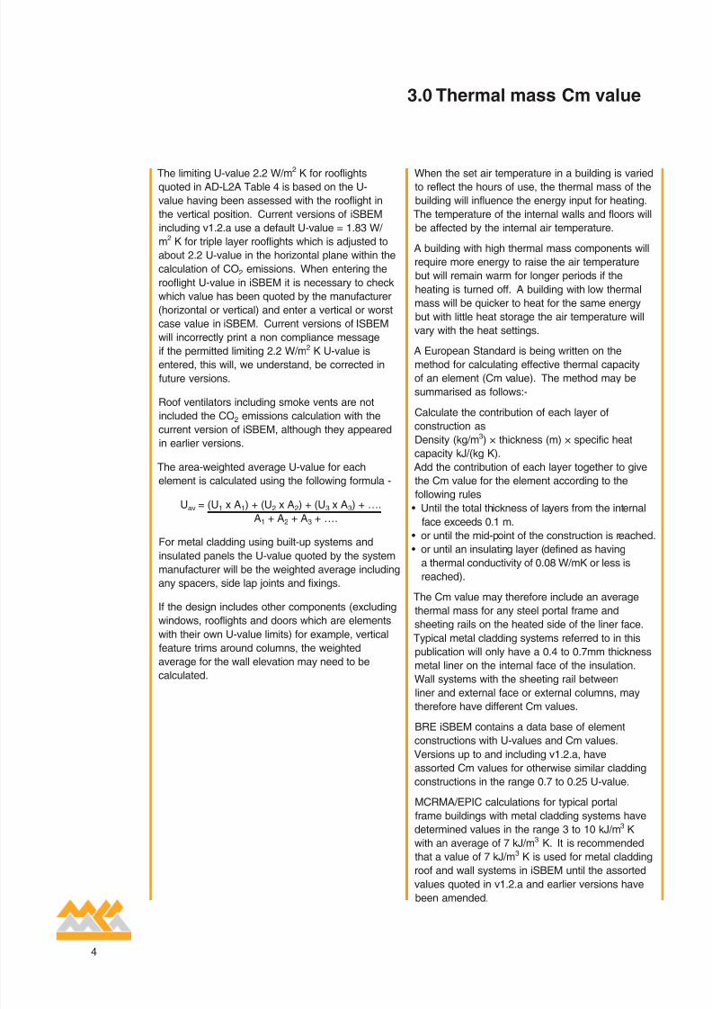
When the set air temperature in a building is variedto reflect the hours of use, the thermal mass of the
building will influence the energy input for heating.
The temperature of the internal walls and floors will
be affected by the internal air temperature.
A building with high thermal mass components will
require more energy to raise the air temperature
but will remain warm for longer periods if the
heating is turned off. A building with low thermal
mass will be quicker to heat for the same energy
but with little heat storage the air temperature will
vary with the heat settings.
A European Standard is being written on themethod for calculating effective thermal capacity
of an element (Cm value). The method may be
summarised as follows:-
Calculate the contribution of each layer of
construction as
Density (kg/m3) × thickness (m) × specific heat
capacity kJ/(kg K).
Add the contribution of each layer together to give
the Cm value for the element according to the
following rules
• Until the total thickness of layers from the internal
face exceeds 0.1 m.
• or until the mid-point of the construction is reached.
• or until an insulating layer (defined as having
a thermal conductivity of 0.08 W/mK or less is
reached).
The Cm value may therefore include an average
thermal mass for any steel portal frame and
sheeting rails on the heated side of the liner face.
Typical metal cladding systems referred to in this
publication will only have a 0.4 to 0.7mm thickness
metal liner on the internal face of the insulation.
Wall systems with the sheeting rail between
liner and external face or external columns, may
therefore have different Cm values.
BRE iSBEM contains a data base of element
constructions with U-values and Cm values.
Versions up to and including v1.2.a, have
assorted Cm values for otherwise similar cladding
constructions in the range 0.7 to 0.25 U-value.
MCRMA/EPIC calculations for typical portal
frame buildings with metal cladding systems have
determined values in the range 3 to 10 kJ/m3 K
with an average of 7 kJ/m3 K. It is recommended
that a value of 7 kJ/m3 K is used for metal cladding
roof and wall systems in iSBEM until the assorted
values quoted in v1.2.a and earlier versions havebeen amended.
The limiting U-value 2.2 W/m2
K for rooflightsquoted in AD-L2A Table 4 is based on the U-
value having been assessed with the rooflight in
the vertical position. Current versions of iSBEM
including v1.2.a use a default U-value = 1.83 W/
m2 K for triple layer rooflights which is adjusted to
about 2.2 U-value in the horizontal plane within the
calculation of CO2 emissions. When entering the
rooflight U-value in iSBEM it is necessary to check
which value has been quoted by the manufacturer
(horizontal or vertical) and enter a vertical or worst
case value in iSBEM. Current versions of ISBEM
will incorrectly print a non compliance message
if the permitted limiting 2.2 W/m2
K U-value isentered, this will, we understand, be corrected in
future versions.
Roof ventilators including smoke vents are not
included the CO2 emissions calculation with the
current version of iSBEM, although they appeared
in earlier versions.
The area-weighted average U-value for each
element is calculated using the following formula -
Uav = (U1 x A1) + (U2 x A2) + (U3 x A3) + ….
A1 + A2 + A3 + ….
For metal cladding using built-up systems and
insulated panels the U-value quoted by the system
manufacturer will be the weighted average including
any spacers, side lap joints and fixings.
If the design includes other components (excluding
windows, rooflights and doors which are elements
with their own U-value limits) for example, vertical
feature trims around columns, the weighted
average for the wall elevation may need to be
calculated.
4
3.0 Thermal mass Cm value

8/11/2019 Design Guide for Metal Roofing and Cladding
http://slidepdf.com/reader/full/design-guide-for-metal-roofing-and-cladding 7/36
5
e.g. using BRE IP 01/06 metal cladding library valuesRoof-wall = 1 ⁄ 3 × (2 × 0.32 eaves + 1 × 1.15 verge)
= 0.60 W/mK.
A more flexible approach is to sum the actual types
of each roof junction length × value divided by
the total perimeter length. For example, four sided
roof of 200m perimeter with parapet and boundary
wall gutters at the eaves
Roof – wall = (120m × 0.79. parapet & gutter +
80m × 0.34 verge & parapet)/200m = 0.61 W/mK.
If values are used in the iSBEM calculation in
place of the default or library value, then these
will be identified in the iSBEM compliance report.
Where better values are used, Building Control
bodies may request justification and copies of
calculations to an approved method.
Other thermal bridges
Other thermal bridges for example, valley gutters
which are not included in the standard menu can be
entered into iSBEM. The current methodology does
not include them in the calculation of energy loss
from the Notional Building, therefore their inclusion
will result in a disproportionate penalty on the
actual building BER and TER against the NotionalBuilding benchmark unless the best recommended
details are adopted and correctly installed.
As a matter of good practice, designers should
adopt details which minimise thermal bridging
irrespective of the requirements of compliance with
the NCM and Building Regulations.
values: regional versions of Building
Regulations
The Building Regulations England and Wales
and Northern Ireland quote BRE IP01/06 as
the reference document for values. The values shown in this document are calculated in
accordance with the methods quoted in BS EN ISO
10211 and BRE IP 01/06.
The Regulations (Scotland) quote values for
typical traditional constructions but do not refer to
IP 01/06 or other sources of evaluated values for
constructions including metal cladding.
In all three regions the values used in
iSBEM calculations may need to be justified by
demonstrating compliance with the method given in
BS EN ISO 10211.
A method to assess the additional heat lossthrough repeating thermal bridges was introduced
by the England and Wales Part AD-L2: 2002. The
additional heat loss for junctions for example, roof
to wall at the eaves is calculated as a linear heat
loss coefficient value (Psi value) W/mK.
System manufacturers should provide values
calculated by competent persons to an approved
method for typical junction details. Currently
values may be calculated using finite element
computer programmes certified to comply with
the method of BS EN ISO 10211. Work is on-
going to refine the method and provide approved
calculations which will be acceptable to Building
Control bodies without further justification.
Worst case basic junction details are illustrated in
sections 8 and 9 of this publication which meet the
BRE IP01/06 values which can be selected from
the library in iSBEM for metal cladding. These
thermal bridge values may be used for insulated
metal twin skin (section 8) and insulated panel
systems (section 9) provided the junction complies
with the relevant illustration and is built to a
reasonable standard of workmanship including
continuity of insulation and air seals.
Alternative recommended junction details are
illustrated in both section 8 and 9 which limit energy
loss through the junction and will provide savings of
CO2 emissions from the building envelope.
Using the recommended MCRMA/EPIC details
and corresponding values will therefore provide
a saving of CO2 emissions for the actual building
BER and resultant target TER. Alternative details
for lower and more energy efficient values may
be provided by system manufacturers for most of
the common junctions.
The building plan and elevation dimensions, except
for height, are not entered into iSBEM, the program
therefore makes assumptions about the length of
a limited number of junction and height/width of
windows etc., which may lead to inaccuracies. In
particular, only one roof-wall value is entered
which includes both the eaves and any verge.
Roof-wall value
The equation used by iSBEM to calculate the
combined eaves & verge detail:-
Roof-wall value = 1 ⁄ 3 × (2 × eaves value + 1 ×
verge value)
4.0 Thermal bridging values

8/11/2019 Design Guide for Metal Roofing and Cladding
http://slidepdf.com/reader/full/design-guide-for-metal-roofing-and-cladding 8/36
Air permeability testing of completed buildingsis mandatory in almost all cases of new build
in England and Wales from April 2006 and in
Northern Ireland from November 2006. The
Scottish Regulations include the same air
permeability limit for use in compliance with the
NCM, although testing buildings at completion is
only mandatory if a lower limit is selected.
The England and Wales Building Regulations
require that the completed building envelope is
tested for air permeability and achieves a standard
of no more than 10 m3 /(h.m2) at 50 Pa pressure.
Better, that is, lower design values of air
permeability may be used for iSBEM compliance
calculations, however the completed building
envelope will have to achieve the stated lower rate
when tested.
The details illustrated in sections 8 and 9 of this
publication are intended with a reasonable standard
of workmanship to achieve the limit of 10 m3 /(h.
m2) at 50 Pa. for metal cladding sections of the
envelope. Air permeability is measured for the
whole envelope and therefore poor quality air
sealing of other materials and components forming
the air barrier may cause greater air loss thanachieved through the metal cladding.
Metal cladding manufacturers will be able to provide
junction details for their systems which achieve
lower air permeability values than the Building
Regulations limit. Where these enhanced details
are used with limited areas of other materials also
designed to minimise air leakage, designs may
consider adopting lower air permeability values.
As building size increases the length of junctions
in metal cladding which may leak, air reduces and
the area of almost impermeable metal claddingincreases. As a result the air permeability of large
buildings should reduce as floor area increases.
The values in Table 3 are suggested as achievable
with metal clad buildings built to a reasonable
standard of workmanship.
Plan area of metal cladbuilding
Air permeability
0 to 2,500 m2 10.0 m3 /(h.m2)
2,501 to 10,000 m2 7.5 m3 /(h.m2)
over 10,000 m2 5 to 6 m3 /(h.m2)
Table 3: Guidance on air permeability vs building size
Minimising condensation risk should be a designcriteria for all buildings for which Building Regulations
refer to the methods of BS 5250. Especially with
high humidity environments such as swimming pools,
designers have to take measures to minimise the
risk of surface condensation which may form near
thermal bridges. Condensation risk analysis is
not included in the compliance requirements of
NCM, but is directly related to best practice for
details with the minimum thermal bridge.
BS 5250: 2002 establishes five classes of internal
humidity by the intended use of the building as
shown in Table 2.
Insulated metal systems which comply with the
U-value for Building Regulations will not normally
be at risk of surface condensation unless there is a
significant thermal bridge.
A surface temperature factor fmin value is calculated
by the approved software programs used to
determine values for thermal bridging. Table
2 shows typical building use with the expected
humidity class and minimum f value necessary to
minimise the risk of condensation forming near
thermal bridges.
Humidityclass
Building type/use Minimumf value
1 Storage areas 0.30
2 Offices, shops 0.50
3 Dwellings with low occupancy 0.65
4 Dwellings with highoccupancy, sports halls,kitchens, canteens;Buildings heated with un-flued gas heaters.
0.80
5 Special buildings for example,laundry, brewery, swimmingpools
0.90
Table 2: Internal humidity classes defined by
BS 5250 and the minimum temperature factor
recommended by building use
The junction details illustrated in sections 8 and 9
of this publication have f values suitable for use in
humidity class 1 to 3.
The recommended details are suitable for
more humid conditions, but designers should
consult the system manufacturer for full product
recommendations in the more severe conditions forexample, swimming pools.
6
5.0 Condensation risk 6.0 Air permeability

8/11/2019 Design Guide for Metal Roofing and Cladding
http://slidepdf.com/reader/full/design-guide-for-metal-roofing-and-cladding 9/36
7
8.1 The value quoted in Table 4 of BRE IP 01/06metal cladding values are included in the menu
of iSBEM and may be selected as junctions
including metal cladding as IP 01/06.
8.2 Constructed with adequate site workmanship
these basic details comply with the
requirements of the Building Regulations for
insulation as a minimum standard which can
and should be improved in the actual design.
8.3 MCRMA and EPIC members have produced
generic details with improved values shown
in each case as figure b; these designs will
reduce CO2 emissions by reducing energy
loss through the junction. This can provide a
reduction on the total building CO2 emissions.
8.4 System manufacturers should be able to provide
other details using their products with values,
calculated by competent persons, which can
be substituted for those illustrated in this guide.
These alternative values can be manually
entered in iSBEM. Building Control bodies may
require proof that any such improved values
are correct and have been used in the actual
construction.
The common types of metal cladding junction whichhave to be entered in iSBEM calculations are
illustrated in section 8 for built-up metal cladding
and section 9 for insulated panel cladding. In each
case a basic design is illustrated which will at least
equal the corresponding worst case value as
quoted in table 4 of BRE IP 01/06. These values
are available from the default menu in iSBEM.
Recommended details with better values are also
illustrated for most junctions which if adopted will
aid compliance with the building’s target emissions.
Specific systems may include improved designs
which should be used to achieve best practice.
The pages may be copied and used as a checklist
for the design against SBEM calculations.
BRE IP 01/06 gives advice that where the value
of a particular junction detail is unknown, but where
the junction detail is as recommended in MCRMA/
EPIC Technical Paper 17 for metal cladding
constructions, then the value of can be taken to
be the value for the equivalent junction detail or it
can be taken to be the default value from Table 4 of
IP 01/06 as appropriate.
The BRE IP 01/06 values for junctions includingmetal cladding are included as the library defaults
in iSBEM, with the exception of roof-wall as
explained in section 4.
Junctiondetail
Library valuefor
correspondingIP 01/06 details
in iSBEM
Detail No. for detailto IP 01/06 criteria
Built-upmetal
Metalpanels
Roof –wall(combineseaves &verge)
0.6 1&2 11&12
Wall groundfloor
1.15 3 13
Wall-wallcorner
0.25 4 14
Wall floornot ground
0.07 5 15
Lintel abovewindow ordoor
1.27 6 16
Sill belowwindow
1.27 7 17
Jamb atwindow ordoor
1.27 8 18
Table 4: Summary of values found in iSBEM
7.0 Junction details -introduction
8.0 Junction details - built-upmetal cladding

8/11/2019 Design Guide for Metal Roofing and Cladding
http://slidepdf.com/reader/full/design-guide-for-metal-roofing-and-cladding 10/36
Detail 1 eaves with gutter for built-up systems
8
Fig 1b Recommended design for eaves
as fig 1a above but the liner sheets do not cross the insulation which is continuous from wall to roof.
value = 0.02 W/mK fmin = 0.95
Key features
• Roof supported gutter avoids thermal bridge issues. Gutters with brackets fixed to walls might require
additional supports, and create thermal bridges.
• Seal all holes and joints in eaves beam to avoid bypassing liner seals.
• All fixings and seals must be to manufacturer’s recommendations.
iSBEM menu provides a single roof-wall value, not the IP 01/06 eaves value.
(see section 4 calculation method for combined roof-wall
value)MCRMA & EPIC Technical Paper 17- detail No. 1 – built-up metal system
Roof ConstructionU = 0.25 W/m2K
Wall ConstructionU = 0.35 W/m2K
Liner fillers
Vented fillers
Gutter support arm
Eaves beam withholes and joints sealed
Typical roof sheetsupported eavesgutter
Eavesflashing
Roof ConstructionU = 0.25 W/m2K
Wall ConstructionU = 0.35 W/m2K
Liner fillers
Vented fillers
Gutter support arm
Eaves beam withholes and joints sealed
Typical roof sheetsupported eavesgutter
Eavesflashing
Fig 1a Basic eaves and gutter
Built-up metal roof construction of 0.25 U-value and 0.35 U-value wall. Roof liner extends to almost touch
the outer sheet or trim of wall, air gap between wall and roof.
value = 0.25 W/mK fmin = 0.76

8/11/2019 Design Guide for Metal Roofing and Cladding
http://slidepdf.com/reader/full/design-guide-for-metal-roofing-and-cladding 11/36
9
Detail 2 verge for built-up metal system
Fig 2b Recommended design for verge
As fig 2a above but with liner sheets that do not cross the insulation which is continuous from wall to roof.
value = 0.02 W/mK fmin = 0.95
Key features
• Cleader angle required to provide structural support and air sealing between purlins. Joints must be
structural and not interfere with seals.
• Fasteners securing cleader angles to purlins must not interfere with seals.
• Seal all holes and joints in cleader angles to avoid bypassing liner seals.
• All fixings and seals must be to manufacturer’s recommendations.
iSBEM menu provides a single roof-wall value, not the IP 01/06 verge value.
(see section 4 calculation method for combined roof-wall
value)MCRMA & EPIC Technical Paper 17- detail No. 2 – built-up metal system
Roof U = 0.25 W/m2K
Wall U = 0.35 W/m2K
Verge flashing
Taped laps
Cleader angle withsealed jointsLiner filler
Roof U = 0.25 W/m2K
Wall U = 0.35 W/m2K
Verge flashing
Taped laps
Cleader angle withsealed jointsLiner filler
Fig 2a Basic verge for built-up metal roof & wall
Built-up system with either roof or wall liner sheet bridging across insulation.
value = 0.28 W/mK fmin =0.79

8/11/2019 Design Guide for Metal Roofing and Cladding
http://slidepdf.com/reader/full/design-guide-for-metal-roofing-and-cladding 12/36
Detail 3 drip sill (junction at base of cladding wall)
10
Fig 3b Recommended design for drip sill
Wall insulation extends down side of floor slab and drip fixed to outer sheet so that it does not bridge
insulation. Floor slab k = 1.0 W/mK.
value = 0.75 W/mK fmin = 0.71
Key features
• The same principles of construction apply to vertical or horizontal profiled external metal cladding.
• Thermal bridging is minimised in the metal construction, provided that the insulation covers at least
100mm of wall/floor.
• The value is largely controlled by the wall/floor materials, light weight blocks for example will improve
the value. Floor assumed 250mm thick and k = 1.0 W/mK.
• Internal trim should be typically 1.5mm thick, with sealed joints.
• The seal at wall/floor junction must be substantial to cater for inevitable variation in concrete/masonry.
• Ensure internal trim fixing heads do not compromise air seals. Use rivets, or remove temporary hex
head types, as work progresses.
• All fixings and seals must be to manufacturer’s recommendations.
Basic IP 01/06 metal cladding = 1.15 W/mK quoted in iSBEM menu.MCRMA & EPIC Technical Paper 17- detail No. 3 – built-up metal system
Fig 3a Basic drip sill below wall Wall to floor junction with little or no wall insulation below floor level.
value = 1.15 W/mK fmin = 0.48
Wall - U = 0.35 W/m2K
Concrete flooror masonry wall
Seal
Liner filler
Sill flashing
Floor/wall seal
Wall - U = 0.35 W/m2K
Concrete flooror masonry wall
Seal
Internal trim (sealed joints)
Liner filler
Closure flashingto contain insulation
Sill/dripflashing

8/11/2019 Design Guide for Metal Roofing and Cladding
http://slidepdf.com/reader/full/design-guide-for-metal-roofing-and-cladding 13/36
11
Detail 4 corner (junction between two perpendicular cladding walls)
Fig 4b Recommended design for insulated corner
As fig 4a above but the liner sheets do not bridge across insulation which is continuous around corner. value = 0.02 W/mK fmin = 0.95
Key features
• The same principles of construction apply to vertical or horizontal profiled external metal cladding.
• The liners must be sealed to the corner trim or cleader and fixed as necessary to ensure the seal is
effective in the long term.
• The insulation fitted around the corner must be continuous.
• The same principles can be used for internal corners.
• Ensure internal trim fixing heads do not compromise air seals. Use rivets, or remove temporary hex
head types, as work progresses.
• All fixings and seals must be to manufacturer’s recommendations.
Basic IP 01/06 metal cladding
= 0.25 W/mK quoted in iSBEM menu.MCRMA & EPIC Technical Paper 17- detail No. 4 – built-up metal system
Fig 4a Basic insulated corner
Built-up cladding with liner bridging insulation
value = 0.25 W/mK fmin = 0.76
Corner Flashing
Wall - U = 0.35 W/m2K
Internal corner trim,with sealed joints
Sealed Laps
Internal corner trim,with sealed joints
Corner Flashing
Wall - U = 0.35 W/m2K
Sealed Laps

8/11/2019 Design Guide for Metal Roofing and Cladding
http://slidepdf.com/reader/full/design-guide-for-metal-roofing-and-cladding 14/36
Detail 5 wall – floor (not ground floor)
12
Fig 5
value = 0.0 W/mK fmin = 1.0
Note. There is no common detail for metal cladding where the floor structure creates a thermal bridge
through the metal clad wall insulation.
Key features
• The same principles of construction apply to vertical or horizontal profiled external metal cladding.
• Identical detail for built-up metal and insulated panel systems, primary fasteners and any spacers
included in U value calculation of the external wall.
• External cladding continues at full thickness pass the floor (does not apply to ground floor) and is fixed
to sheeting rails.
• No fasteners penetrate the wall insulation and floor or support beam.
Gap between floor and wall liner is filled with insulation e.g. fire stopping product.
Basic IP 01/06 metal cladding
= 0.07 W/mK quoted in iSBEM menu.MCRMA & EPIC Technical Paper 17- detail No. 5 – built-up metal system
Wall - U = 0.35 W/m2K
Intermediate floor(not ground bearing)
Profiled metal linercontinues past floor
Profiled firestopping filler

8/11/2019 Design Guide for Metal Roofing and Cladding
http://slidepdf.com/reader/full/design-guide-for-metal-roofing-and-cladding 15/36
13
Detail 6 window or door head
Fig 6b Recommended design with insulation board between soffit and rail
value = 0.05 W/mK fmin = 0.95
Key features
• The same principles of construction apply to vertical or horizontal profiled external metal cladding.
• An insulation board should be fitted between both external soffit/internal trim and rail.
• It is important to keep the soffit flashing separate from the internal trim.
Basic IP 01/06 metal cladding = 1.27 W/mK quoted in iSBEM menu.MCRMA & EPIC Technical Paper 17- detail No. 6 – built-up metal system
Fig 6a Basic window or door head
value = 1.27 W/mK fmin = 0.46
Window/door framesealed to trim
Wall - U = 0.35 W/m2K
Internal trim
Seal
Seal holesin rail
Liner filler
Headflashing
Externalsoffit
Window/door framesealed to trim and soffit
Wall - U = 0.35 W/m2K
Internal trim
Seal
Insulationboard
Seal holesin rail
Liner filler
Headflashing
Externalsoffit

8/11/2019 Design Guide for Metal Roofing and Cladding
http://slidepdf.com/reader/full/design-guide-for-metal-roofing-and-cladding 16/36
Detail 7 window sill
14
Fig 7b Recommended design for an insulated sill
value = 0.05 W/mK fmin = 0.95
Key features
• The same principles of construction apply to vertical or horizontal flat or profiled external metal cladding.
• An insulation board should be fitted between both external sill/internal trim and rail.
• It is important to keep the sill flashing separate from the internal trim.
Basic IP 01/06 metal cladding = 1.27 W/mK quoted in iSBEM menu.MCRMA & EPIC Technical Paper 17- detail No. 7 – built-up metal system
Fig 7a Basic design for sill
value = 1.27 W/mK fmin = 0.46
Window framesealed to trim and sill
Wall - U = 0.35 W/m2K
Seal holesetc in frame
Seal
Internal trim
Liner filler
Sillflashing
Window framesealed to trim and sill
Wall - U = 0.35 W/m2
K
Seal holesetc in frame
Insulationboard
Seal
Internal trim
Liner filler
Sillflashing

8/11/2019 Design Guide for Metal Roofing and Cladding
http://slidepdf.com/reader/full/design-guide-for-metal-roofing-and-cladding 17/36
15
Detail 8 window or door jamb
Fig 8b Recommended design for an insulated jamb
value = 0.05 W/mK fmin = 0.95
Key features
• The same principles of construction apply to vertical or horizontal flat or profiled external metal cladding.
• An insulation board should be fitted between both external jamb/internal trim and rail.
• It is important to keep the jamb flashing separate from the internal trim.
Basic IP 01/06 metal cladding
= 1.27 W/mK quoted in iSBEM menuMCRMA & EPIC Technical Paper 17- detail No. 18 –insulated panels
Fig 8a Basic jamb for window or door frame
value = 1.27 W/mK fmin = 0.46
Window/door framesealed to trim and jamb
Wall - U = 0.35 W/m2K
Internal trim
Seal
Seal holesetc in frame
Liner sealed to framing
Jambflashing
Window/door framesealed to trim and jamb
Wall - U = 0.35 W/m2K
Internal trim
Seal
Insulationboard
Seal holesetc in frame
Liner sealed to framing
Jambflashing

8/11/2019 Design Guide for Metal Roofing and Cladding
http://slidepdf.com/reader/full/design-guide-for-metal-roofing-and-cladding 18/36
Detail 9 valley gutter for built-up metal system
16
Fig 9 Valley gutter
Built-up metal roof of 0.25 U-value roof and 0.35 U-value gutter.
value = 1.95 W/mK fmin = 0.64
Improved values are available for particular systems with thermal breaks at gutter head e.g. , value =
0.39 W/mK fmin = 0.95, consult manufacturer for details.
Key features
• Gutter thickness and thermal bridging detail will vary, depending on manufacturer; manufacturer’s
accredited designs may have values better than 0.50 W/mK.
• Ideally, the metal gutter outer surface should not bridge the insulation layer.
• In all designs the roof liner should not bridge the gutter insulation layer.
• If the gutter is a traditional pre-2002 design, the thermal bridge value will exceed that quoted.
• Insulation must fill the gutter liner, leaving no voids.
• All joints in gutter flanges must be sealed.
• All fixings and seals must be to manufacturer’s recommendations.
No value for a valley gutter is quoted in iSBEM menu, the value and gutter length can be added on
the roof construction input page.MCRMA & EPIC Technical Paper 17- detail No. 9 – built-up metal systems
Factory insulated valley gutter
Eaves Flashing
Roof U = 0.25 W/m2KVented eaves filler
Liner filler

8/11/2019 Design Guide for Metal Roofing and Cladding
http://slidepdf.com/reader/full/design-guide-for-metal-roofing-and-cladding 19/36
Detail 10 ridge trim built-up metal system
17
Fig 10 Ridge Trim – built-up metal roof construction of 0.25 U-value.
value = 0.01 W/mK fmin = 0.95
Fully insulated as shown a ridge trim should not form a significant thermal bridge in a roof construction.
Key features of the design and workmanship are• Insulation must be continuous over the ridge.
• If canister applied foam insulation is used, it will also act as a partial air barrier.
• Inner ridge trim can be flat or profiled, but in either case must be sealed at laps and at joints with the
roof liner.
• The ridge flashing should be fixed through, or downslope from the filler when fillers are set back 80 to
100mm to avoid bird damage.
• The filler must be kept clear of roof fasteners, ideally downslope.
• All fixings and seals to manufacturer’s recommendations.
• On most roofs with well constructed ridge as detailed above, the additional heat loss is so small that
there is no need to enter the ridge in SBEM.
No value for a ridge is quoted in iSBEM menu, the value and ridge length can be added on the roof
construction input page.MCRMA & EPIC Technical Paper 17- detail No. 10 – built-up metal systems
Ridge Flashing
Continuous Insulation
Vented Ridge Filler
Liner Filler
Inner Ridge Trimwith TapedEnd Laps Roof Construction
U = 0.25 W/m2K
8/11/2019 Design Guide for Metal Roofing and Cladding
http://slidepdf.com/reader/full/design-guide-for-metal-roofing-and-cladding 20/36
9.1 The value quoted in Table 4 of BRE IP 01/06metal cladding values are included in the menu
of iSBEM as junctions including metal cladding
as IP 01/06.
9.2 Constructed with adequate site workmanship
these basic generic details comply with the
requirements of the Building Regulations for
insulation as a minimum standard, which can
and should be improved in the actual design.
9.3 EPIC and MCRMA members have produced
recommended details with improved values
shown in each case as figure b, these designs
will reduce CO2 emissions by reducing energy
loss through the junction. This can provide a
significant reduction on the total building CO2
emissions.
9.4 System manufacturers should be able to provide
other details using their products with values,
calculated by competent persons, which can
be substituted for those illustrated in this guide.
These alternative values can be manually
entered in iSBEM. Building Control bodies may
require proof that any such improved values
are correct and have been used in the actual
construction.
18
9.0 Junction details –insulated metal panels

8/11/2019 Design Guide for Metal Roofing and Cladding
http://slidepdf.com/reader/full/design-guide-for-metal-roofing-and-cladding 21/36
19
Detail 11 eaves with gutter for insulated panels
Fig11b Recommended design for eaves with gutter
As fig 11a above but with insulation in corner and liner which does not cross the insulation.
value = 0.02 W/mK fmin = 0.95
Key features
• Roof supported gutter avoids thermal bridge issues. Gutters with brackets fixed to walls might require
additional supports, and create thermal bridges.
• Seal all holes and joints in eaves beam to avoid bypassing liner seals.
• All fixings and seals must be to manufacturer’s recommendations.
iSBEM menu provides a single roof-wall value not the IP 01/06 eaves value.
(see section 4 calculation method for combined roof-wall
value)MCRMA & EPIC Technical Paper 17- detail No. 11 – insulated panels
Fig11a Eaves with gutter
insulated panel roof and liner across top of wall panel
value = 0.25 W/mK fmin = 0.76
Roof ConstructionU = 0.25 W/m2K
Wall ConstructionU = 0.35 W/m2K
Seals between eaves beamand panel liners
Gutter support arm
Eaves beam withholes and joints sealed
Typical roof sheetsupported eavesgutter
Roof ConstructionU = 0.25 W/m2K
Wall ConstructionU = 0.35 W/m2K
Seals between eaves beamand panel liners
Site insulation
Gutter support arm
Eaves beam withholes and joints sealed
Typical roof sheetsupported eavesgutter
Eavesflashing

8/11/2019 Design Guide for Metal Roofing and Cladding
http://slidepdf.com/reader/full/design-guide-for-metal-roofing-and-cladding 22/36
Detail 12 verge for insulated panels
20
Fig 12b Recommended design for verge
As fig 1a above but the liner sheets do not cross the insulation which is continuous from wall to roof.
value = 0.02 W/mK fmin = 0.95
Key features
• Cleader angle required to provide structural support and air sealing between purlins. Joints must be
structural and not interfere with seals.
• Fasteners securing cleader angles to purlins must not interfere with seals.
• Seal all holes and joints in cleader angles to avoid bypassing liner seals.
• All fixings and seals must be to manufacturer’s recommendations.
iSBEM menu provides a single roof-wall value not the IP 01/06 verge value.
(see section 4 calculation method for combined roof-wall
value)MCRMA & EPIC Technical Paper 17- detail No. 12 – insulated panels
Roof U = 0.25 W/m2K
Wall U = 0.35 W/m2K
Verge flashing
Cleader angle withsealed joints
Liners sealed to cleader
Roof U = 0.25 W/m2K
Wall U = 0.35 W/m2K
Verge flashing
Cleader angle withsealed joints
Liners sealed to cleader
Block insulation
Fig 12a Basic design for verge
Verge of insulated panel with wall liner passing insulation of the roof.
value = 0.28 W/mK fmin = 0.79

8/11/2019 Design Guide for Metal Roofing and Cladding
http://slidepdf.com/reader/full/design-guide-for-metal-roofing-and-cladding 23/36
21
Detail 13 drip sill (junction at base of cladding wall)
Fig 13b Recommended design of drip sill
As fig 1a above with increased wall depth below floor and floor k = 1.0 W/mK.
value = 0.99 W/mK fmin = 0.70
Key features• Flat or profiled external metal cladding may be vertical or horizontal; the same principles of construction
apply.
• Thermal bridging is minimised in the metal construction, provided that the insulation covers at least
100mm of wall/floor. The liner and sill of flat panel systems bridge the insulation.
• The value is largely controlled by the wall/floor materials, light weight blocks for example will improve
the value. Floor assumed 250mm thick and k = 1.0 W/mK.
• Internal trim should be typically 1.5mm thick, with sealed joints.
• The seal at wall/floor junction must be substantial to cater for inevitable variation in concrete/masonry.
• Ensure internal trim fixing heads do not compromise air seals. Use rivets, or remove temporary hex
head types, as work progresses.
• All fixings and seals must be to manufacturer’s recommendations.
IP 01/06 metal cladding value = 1.15 quoted in iSBEM menuMCRMA & EPIC Technical Paper 17- detail No. 13 – insulated panels
Fig 13a Basic drip trim below wall
Insulated panel wall stops almost level with floor. value = 1.15 W/mK fmin = 0.48
Wall - U = 0.35 W/m2K
Concrete flooror masonry wall
Seal
Internal trim (sealed joints)
Liner seal
Sill/dripflashing
Wall - U = 0.35 W/m2K
Concrete flooror masonry wall
Seal
Internal trim (sealed joints)
Liner seal
Sill/dripflashing

8/11/2019 Design Guide for Metal Roofing and Cladding
http://slidepdf.com/reader/full/design-guide-for-metal-roofing-and-cladding 24/36
Detail 14 corner (junction between two perpendicular cladding walls)
22
Fig 14b Recommended design for insulated corner
As fig 1a above but the liner does not cross the insulation which fills corner trim.
value = 0.02 W/mK fmin = 0.95
Key features
• Flat or profiled external metal cladding may be vertical or horizontal; the same principles of construction
apply.
• The liners must be sealed to the corner trim or cleader and fixed as necessary to ensure the seal is
effective in the long term.
• The corner trim must be filled with insulation.
• The same principles can be used for internal corners.
• Ensure internal trim fixing heads do not compromise air seals. Use rivets, or remove temporary hex
head types, as work progresses.
• All fixings and seals must be to manufacturer’s recommendations.
IP 01/06 metal cladding value = 0.25 quoted in iSBEM menuMCRMA & EPIC Technical Paper 17- detail No. 14 –insulated panels
Fig 14a Basic insulated corner
Insulated panel corner with liner bridging insulation.
value = 0.25 W/mK fmin = 0.76
Corner Flashing Wall - U 0.35 w/m2K
Cleader angle withsealed joints
Liners sealed to cleader
Block Insulation
Cleader angle withsealed joints
Corner Flashing Wall - U 0.35 w/m2K
Liners sealed to cleader

8/11/2019 Design Guide for Metal Roofing and Cladding
http://slidepdf.com/reader/full/design-guide-for-metal-roofing-and-cladding 25/36
23
Detail 15 wall – floor (not ground floor)
Fig 15
value = 0.0 W/mK fmin = 1.0
Note. There is no common detail for metal cladding where the floor structure creates a thermal bridge
through the metal clad wall insulation.
Key features
• The same principles of construction apply to vertical or horizontal flat or profiled external metal cladding.
• Identical detail for built-up metal and insulated panel systems, primary fasteners and any spacers
included in U value calculation of the external wall.
• External cladding continues at full thickness past the floor (does not apply to ground floor) and is fixed
to sheeting rails.
• No fasteners penetrate the wall insulation and floor or support beam.
• Gap between floor and wall liner is filled with insulation for example, fire stopping product.
Basic IP 01/06 metal cladding
= 0.07 W/mK quoted in iSBEM menu.MCRMA & EPIC Technical Paper 17- detail No. 15 – insulated panel
Wall - U = 0.35 W/m2K
Intermediate floor(not ground bearing)
Profiled metal linercontinues past floor
Profiled firestopping filler

8/11/2019 Design Guide for Metal Roofing and Cladding
http://slidepdf.com/reader/full/design-guide-for-metal-roofing-and-cladding 26/36
Detail 16 window or door head
24
Fig 16b Recommended design with insulation between soffit and rail
value = 0.70 W/mK fmin = 0.58
Key features
• The same principles of construction apply to vertical or horizontal flat or profiled external metal cladding.
• An insulation board should be fitted between both external soffit/internal trim and rail.
• It is important to keep the soffit flashing separate from the internal trim.
Basic IP 01/06 metal cladding
= 1.27 W/mK quoted in iSBEM menu.MCRMA & EPIC Technical Paper 17- detail No. 16 –insulated panel
Window/door framesealed to trim and soffit
Wall - U = 0.35 W/m2K
Internal trim
Seal
Seal holesin rail
Liner seal
Headflashing
Externalsoffit
Fig 16a Basic window or door head
value = 1.27 W/mK fmin = 0.46
Window/door framesealed to trim and soffit
Wall - U = 0.35 W/m2K
Internal trim
Seal
Insulationboard
Seal holesin rail
Liner seal
Headflashing
Externalsoffit

8/11/2019 Design Guide for Metal Roofing and Cladding
http://slidepdf.com/reader/full/design-guide-for-metal-roofing-and-cladding 27/36
25
Detail 17 window sill
Fig 17b Recommended design for insulated sill
value = 0.03 W/mK fmin = 0.96
Key features
• The same principles of construction apply to vertical or horizontal flat or profiled external metal cladding.
• An insulation board should be fitted between both external sill/internal trim and rail.
• It is important to keep the sill flashing separate from the internal trim.
Basic IP 01/06 metal cladding
= 1.27 W/mK quoted in iSBEM menuMCRMA & EPIC Technical Paper 17- detail No. 17 – insulated panels
Fig 17a Basic window sill
value = 1.27 W/mK fmin = 0.46
Window framesealed to trim and sill
Wall - U = 0.35 W/m2K
Seal holesetc in frame
Seal
Internal trim
Liner seal
Sillflashing
Window framesealed to trim and sill
Wall - U = 0.35 W/m2K
Seal holesetc in frame
Insulationboard
Seal
Internal trim
Liner seal
Sillflashing
Infillinsulation

8/11/2019 Design Guide for Metal Roofing and Cladding
http://slidepdf.com/reader/full/design-guide-for-metal-roofing-and-cladding 28/36
Internal trim
Seal
Seal holesetc in frame
Jambflashing
Wall - U = 0.35 W/m2K
Window/door framesealed to trim and jamb
Liner seal
Internal trim
Seal
Seal holesetc in frame
Jambflashing
Wall - U = 0.35 W/m2K
Insulationboard
Window/door framesealed to trim and jamb
Liner seal
Detail 18 window or door jamb
26
Fig 18b Recommended design for insulated jamb
As fig 1a above but the liner sheets do not cross the insulation which is continuous from wall to roof.
value = 0.03 W/mK fmin = 0.96
Key features
• The same principles of construction apply to vertical or horizontal flat or profiled external metal cladding.
• An insulation board should be fitted between both external jamb/internal trim and rail.
• It is important to keep the jamb flashing separate from the internal trim.
Basic IP 01/06 metal cladding
= 1.27 W/mK quoted in iSBEM menuMCRMA & EPIC Technical Paper 18- detail No. 18 –insulated panels
Fig 18a Basic jamb for widow or door frame
value = 1.27 W/mK fmin = 0.46

8/11/2019 Design Guide for Metal Roofing and Cladding
http://slidepdf.com/reader/full/design-guide-for-metal-roofing-and-cladding 29/36
27
Detail 19 valley gutter for metal panel system
Fig 19 Valley gutter
Insulated panel roof of 0.25 U-value roof and 0.35 U-value gutter.
value = 1.95 W/mK fmin = 0.64
Improved values are available for particular systems with thermal breaks at gutter head e.g. , value =
0.39 W/mK fmin = 0.95, consult manufacturer for details.
Key features
• Gutter thickness and thermal bridging detail will vary, depending on manufacturer, manufacturer’s
accredited designs may have values better than 0.50 W/mK.
• Ideally, the metal gutter outer surface should not bridge the insulation layer.
• In all designs the roof liner should not bridge the gutter insulation layer.
• If the gutter is a traditional pre 2002 design, the thermal bridge value will exceed that quoted.
• Insulation must fill the gutter liner, leaving no voids.
• All joints in gutter flanges must be sealed.
• All fixings and seals must be to manufacturer’s recommendations.
No value for a valley gutter is quoted in iSBEM menu, the value and gutter length can be added on
the roof construction input page.MCRMA & EPIC Technical Paper 17- detail No. 19 – insulated panels
Factory insulated valley gutter
Roof U = 0.25 W/m2K
Seal liner to gutter

8/11/2019 Design Guide for Metal Roofing and Cladding
http://slidepdf.com/reader/full/design-guide-for-metal-roofing-and-cladding 30/36
Detail 20 ridge trim metal panel system
28
Fig 20 Recommended ridge trim
Insulated panel metal roof construction of 0.25 U-value.
value = 0.01 W/mK fmin = 0.95
Fully insulated as shown a ridge trim should not form a significant thermal bridge in a roof construction.
Key features of the design and workmanship are• Insulation must be continuous over the ridge.
• If canister applied foam insulation is used, it will also act as a partial air barrier.
• Inner ridge trim can be flat or profiled, but in either case must be sealed at laps and at joints with the
roof liner.
• The ridge flashing should be fixed through, or downslope from the filler when fillers are set back 80 to
100mm to avoid bird damage.
• The filler must be kept clear of roof fasteners, ideally downslope.
• All fixings and seals to manufacturer’s recommendations.
• On most roofs with well constructed ridge as detailed above, the additional heat loss is so small that
there is no need to enter the ridge in SBEM.
No value for a ridge is quoted in iSBEM menu, the value and ridge length can be added on the roof
construction input page.
MCRMA & EPIC Technical Paper 17- detail No. 20 – insulated panels
Ridge Filler
Ridge Flashing
Site Installed Insulation
Roof ConstructionU = 0.25 W/m2K
Seal Liner to Inner Trim
Inner Ridge Trimwith TapedEnd Laps

8/11/2019 Design Guide for Metal Roofing and Cladding
http://slidepdf.com/reader/full/design-guide-for-metal-roofing-and-cladding 31/36
29
Element iSBEM default values
Other values (typical) required for entryof metal cladding systems into iSBEM
Roof – metal twin skinor insulated panel
0.25 U-value W/m2 K areaweighted average (0.35 for anyindividual element)
Enter as flat in iSBEM if less than 10˚ pitch.Cm = 7 kJ/m2 K (typical insulated metalsystem)
Wall– metal twin skin orinsulated panel
0.35 U-value W/m2 K areaweighted average, exceptScotland 0.30 U-value W/m2 Karea weighted average (0.70 forany individual element)
Cm = 7 kJ/m2 K (typical insulated metalsystem)
JunctionsThermal bridges for
metal cladding (IP01/06 values)
Roof – wallWall ground floorWall – wall cornerWall – floor not groundLintel above window ordoorSill below windowJamb at window or door
As-built values W/mK, shouldbe no worse than
0.601.150.250.07
1.271.271.27
See fig 1 to 8 for built-up and 11to 18 for panels
Recommended details are shown inpreceding sections 8 & 9 with better
values.
See fig 1A to 8A for built-up and 11A to18A for panels.
Improved designs may be available fromsystem manufacturers for their specific junction designs.
Profiled in planerooflights 2.2 U-value W/m
2
K areaweighted average e.g. triple skinprofiled in plane plastic.
up to 20% of roof area.
No frame.T solar = 0.5L solar =0.5Surface area ratio = 1.0Transmission factor = 1.0
Pedestrian doors 2.2 U-value W/m2 K areaweighted average (3.0 for anyindividual element)
Cm = 6.8 kJ/m2 K (iSBEM default)
Vehicle access doors 1.50 U-value W/m2 K areaweighted average (4.0 for anyindividual element)
Cm = 4.9 kJ/m2 K (iSBEM default)
Roof ventilatorsincluding smoke vents
6.0 U-value W/m2 K areaweighted average and any
individual element.
Note: Not included in current version ofiSBEM calculation.
Table 5: Checklist of recommended data entry for AD-L2A England and Wales, Part F Northern Ireland,
Section 6 Scotland using BRE iSBEM.
10.0 Checklist forrecommended data entry

8/11/2019 Design Guide for Metal Roofing and Cladding
http://slidepdf.com/reader/full/design-guide-for-metal-roofing-and-cladding 32/36
The following case study illustrates the relativemagnitude of % CO2 emission savings obtainable
on this particular design and selected services
using iSBEM v1.2.a + patch 01. The actual % CO2
emission savings on any particular design will vary
with dimensions, intended use, installed services
and fabric etc.
The case study achieved the target asset rating,
76% CO2 emission savings against the notional
building, as the benchmark before any changes.
The size of % CO2 emission savings for any
selected design change varies according to how
well the whole building complies.
Principal design factors for case study
Warehouse/industrial unit with small office, located
in Birmingham
60 m long × 40 m wide 6 m to eaves
Portal frame construction.
Twin skin insulated metal roof 0.25 U value, with
15% triple skin rooflights 1.83 U-value (assessed in
vertical position).
Insulated panel walls 0.35 U value
Junction details having manufacturer’s values
better than BRE IP 01/06 table 4.
30
11.0 Case study: portalframe metal clad building
Figure 21: Case Study – 2,400m 2 portal frame metal clad industrial/warehouse unit.
Mains gas heating, boiler for offices, radiant heaterfor warehouse.
Full lighting design available based on watts/m2 of
floor area and CIBSE guidelines.
No renewable energy sources.
Emission results calculated using iSBEM
Design ofbuilding forplanning andconstructionBER
23.45kg CO2 /m
2Initial design wasoptimised byimproving lighting,heating servicesand junction details
NotionalBuilding
30.76kg CO
2 /m2
Targetemissions forcompliance withthe standard ofAD-L2A TER
23.52kg CO2 /m
2
Asset ratingas % of thatproduced bynotional building
76% Initial designabout 110% beforeoptimisation
Table 6: Case study energy use

8/11/2019 Design Guide for Metal Roofing and Cladding
http://slidepdf.com/reader/full/design-guide-for-metal-roofing-and-cladding 33/36
31
The magnitude of savings varies according to whichversion of iSBEM is used and not necessarily in
a predictable manner. Since older versions of
the approved software remain in use for existing
Building Control applications, the user should
always ensure that they have the appropriate
version of SBEM, which may not reproduce the
above level of savings.
The case study was set in Birmingham, if the
building was in London the calculated CO2
emissions would increase by 3%. This value
provides a rough guide to the significance of the
above changes to the fabric and services.
About 51 % of the calculated kwh for the equivalentNotional Building are caused by electricity used
for lighting. One kilowatt of mains grid supplied
electricity is converted to 0.422 kg CO2 whereas
one kilowatt of natural gas converts as less than
half the emissions to 0.194 kg CO2, see Table 2 of
AD-L2A.
Reducing the lighting energy usage from the
Notional Building level to that accepted as practical
in CIBSE guidelines and installing manual-on
automatic-off switching in the warehouse and office
reduced the CO2 emissions by 9%.
The second major source of emissions is the
controlled services for space heating (and cooling
if installed). Changes from forced air convectors
to multiburner radiant heaters in the warehouse
provided calculated savings of 15% CO2 emissions
in this example.
In contrast, improving the U-value of the roof from
0.25 to 0.20 and walls from 0.35 to 0.30 W/m2 K
only reduced emissions by 2%.
The 2002 changes to Part L introduced a permitted
10% of heat loss through the building envelope
by means of unavoidable thermal bridging at junctions etc. The values entered into the iSBEM
calculation evaluate this heat loss and consequent
CO2 emissions. Improving values from the worst
permitted case values published in BRE IP 01/06
to manufacturer’s recommended details saved 3%
emissions.
Reducing the air permeability of the envelope for
this open space building only reduces % emissions
by a small amount using the current version of
iSBEM, whereas previous versions calculated a
significant saving.
Changing the area of profiled GRP or
Polycarbonate rooflights from 10% to the permitted
maximum of 20% of roof area causes a small
increase in CO2 emissions according to the current
version of iSBEM. If solar gain is added to future
versions of iSBEM the relationship may change.
The NARM guide to rooflights illustrates the case
where photoelectric switching can save emissions if
used with increased levels of daylight.
NOTE: Experience has shown that particular design
changes may produce widely different
magnitudes of energy saving when applied
to different types and sizes of building.

8/11/2019 Design Guide for Metal Roofing and Cladding
http://slidepdf.com/reader/full/design-guide-for-metal-roofing-and-cladding 34/36
The value for a junction can only be calculatedusing finite element two and three dimensional
analysis. The accredited details for dwellings have
been calculated by this method and published
for typical junction details on the Government’s
web site. Provided that the as-built details comply
with these published generic designs and a good
level of workmanship is achieved, the contractor
may use the library values in iSBEM quoted for
accredited details.
Currently, no similar approved scheme is available
for junctions including metal roof and wall
cladding. The junction details figures 1 to 20 in this
publication and the Table 4 default junction values
in BRE IP 01/06 have been calculated by finite
element analysis.
MCRMA and EPIC members have established
extensive libraries of typical junction details for
their systems since the 2002 changes to Building
Regulations based on similar numerical analysis.
BS EN ISO 10211 sets the compliance criteria for
finite element analysis programmes which can be
used for this type of analysis.
Government-backed work is currently in progress
to establish guidelines for users of the approvedprogrammes to reduce the variation between
operators which has been identified by round robin
testing. A number of reports will be published
recording the results of this work.
MCRMA Technical Paper 18 has been published
as part of the work to improve guidelines and
reduce variations between operators of finite
element analysis programmes for thermal bridges
in insulated metal cladding systems.
Readers should consult the EPIC and MCRMA web
sites for the latest updates on this work.
Figure 22: Typical heat flow pattern through insulated
metal junction determined by finite element analysis.
The regional versions of the Building Regulationsrefer to BR 443: 2006 Edition – Conventions for
U-value Calculations, which provides methods for
most building materials using the methods of BS
EN ISO 6946. Section 4.10 of BR 443 for metal-
faced roofing and wall cladding states:-
The U-value of metal-clad walls and roofs needs
to take account of joints between panels and any
metallic components within the insulation, including
through fixings. The MCRMA Technical Paper 14
sets out the principles and contains information on
how to carry out the calculations.
The method of finite element analysis set out in
MCRMA Technical Paper No 14 :2002 remains
valid, a more detailed explanation is provided in
MCRMA Technical Paper 18 :2006. A number of
commercial software packages are available which
comply with BS EN ISO 10211 and may be used
for this type of work.
Finite element analysis is normally used for
insulated panels where the heat flow through joints
is not perpendicular to the panel surface.
Twin skin metal systems with spacers which
penetrate the insulation layer may be calculated byfinite element analysis or in accordance with the
following
The BRE U-value program provides a convenient
calculation method for either Z-spacer or rail-and-
bracket systems. It cannot be used for insulated
panels or junction details.
EPIC and MCRMA members will provide U values
calculated for their products using one of these
methods.
Work is currently on-going to reduce the operator
sensitivity of some finite element software whenapplied to complex often three dimensional metal
bridges through insulation, by round robin testing,
see Appendix B.
32
Appendix AMethod of calculating
U value for metal cladding
Appendix BMethod of calculating value for metal cladding

8/11/2019 Design Guide for Metal Roofing and Cladding
http://slidepdf.com/reader/full/design-guide-for-metal-roofing-and-cladding 35/36
33
Building RegulationsEngland & Wales
AD-L2A Conservation of fuel and power
in new buildings other than
dwellings – 2006 edition.
AD-L2B Conservation of fuel and
power in existing buildings
other than dwellings – 2006
edition – obtainable from www.
planningportal.gov.uk
Northern Ireland
Part F2 Conservation of Fuel and Energy
– 2006 – obtainable from www.
dfpni.gov.uk
Scotland
Section 6 Energy – 2007 – obtainable from
www.sbsa.gov.uk
National Calculation Methodology
iSBEM obtainable from www.ncm.bre.co.uk
Building Research Publications
BRE IP 01/06 Assessing the effects of thermal
bridging at junctions and around
openings. BRE 2006.
BR 443 Conventions for U-valuecalculations. BRE 2006 edition.
British Standards
BS EN ISO 6946 Thermal performance of buildings
and building components
– Thermal resistance and thermal
transmittance – Calculation
method.
BS EN ISO 10211 Thermal bridges in building
construction – Heat flows and
surface temperatures.
BS 5250: 2002 Code of practice for control of
+ amendment 1 condensation in buildings.
Other Publications
MCRMA Guidance for the design of metal
Technical roofing and cladding to comply
Paper 14 with approved document L2: 2001.
MCRMA Conventions for calculating
Technical U-values, f-values and values
Paper 18 for metal cladding systems
systems using two- and three-
dimensional thermal calculations.
NARM Designing with rooflights:
supporting the guidance in Ad-L2A & AD-L2B (2006).
Appendix CReference Documents
No 1 Recommended good practice for daylightingin metal clad buildings
No 2 Curved sheeting manual
No 3 Secret fix roofing design guide
No 4 Fire and external steel-clad walls: guidance
notes to the revised Building Regulations,
1992 (out of print )
No 5 Metal wall systems design guide
No 6 Profiled metal roofing design guide
No 7 Fire design of steel-clad external walls
for building: construction, performance
standards and design
No 8 Acoustic design guide for metal roof and
wall cladding
No 9 Composite roof and wall cladding panel
design guide
No 10 Profiled metal cladding for roof and
walls: guidance notes on revised Building
Regulations 1995 parts L & F (out of print )
No 11 Metal fabrications: design, detailing and
installation guide
No 12 Fasteners for metal roof and wall cladding:
design detailing and installation guide
No 13 Composite slabs and beams using steeldecking: best practice for design and
construction
No 14 Guidance for the design of metal roofing and
cladding to comply with Approved Document
L2: 2001
No 15 New Applications: composite construction
No 16 Guidance for the effective sealing of end lap
details in metal roofing constructions.
No 17 Design guide for metal roofing and cladding
to comply with energy requirements of UK
Building Regulations (2006)
No 18 Conventions for calculating u-values, f-values and -values for metal cladding
systems using two- and three-dimensional
thermal calculations.
LiabilityWhilst the information contained in this design guide is believed
to be correct at the time of going to press, the Metal Cladding and
Roofing Manufacturers Association Limited and Engineered Panels
in Construction Limited and their member companies cannot be
held responsible for any errors or inaccuracies and, in particular,
the specification for any application must be checked with the
individual manufacturer concerned for a given installation.
The diagrams of typical constructions in this publication areillustrative only.
MCRMA technical papers
Updates and news on metal cladding and related building control issues are available from
www.mcrma.co.uk and www.epic.uk.com.

8/11/2019 Design Guide for Metal Roofing and Cladding
http://slidepdf.com/reader/full/design-guide-for-metal-roofing-and-cladding 36/36
THE METAL CLADDING & ROOFING MANUFACTURERS ASSOCIATION LIMITED
18 MERE FARM ROAD
PRENTON
.
WIRRALCHESHIRE CH43 9TT
TELEPHONE: 0151 652 3846
FACSIMILE: 0151 653 4080
www.mcrma.co.uk
n d p
r i n t e d b y H i g h l i g h t D i g i t a l I m a g i n g a n d P r i n t