design for additive manufacturing - geometric an hcl ... · conformal cooling hydrovision . ......
TRANSCRIPT
Design for Additive Manufacturing
Geometric, Eindhoven
January 29, 2015

“INCREASE THE COMPETITIVENESS OF COMPANIES THROUGH TECHNOLOGICAL INNOVATIONS”
Sirris | Driving industry by technology
Who are we?
• Collective centre of the technology industry
• Industry owned & approved • 140 technological experts • Serving 5000 clients, 80% SME

‣ Layerwise manufacturing
‣ Always starts from 3D CAD model
‣ Famous for prototyping
‣ Functional products with good
mechanical properties
© Materialise
3
Additive manufacturing

Sirris | 25 years of Additive Manufacturing
AM centre – Leading position in EU • 18 (+2) engineers and technicians • 12+ high-tech additive technologies in house • Most complete installed base in EU • Driving technology companies in applications
‣ Material research & development
‣ Technology development
‣ Design for AM
‣ Knowledge transfer
‣ Tailor made advice

ICT
& d
esi
gn
too
ls
Process Leading-edge applications & components
Materials Post-
Process
AM | Value chain & target groups

material efficiency
flow optimization
integration of functions
mass customization
Tuning of mechanical properties
Custom porosities
COST REDUCTION
DRIVERS FOR ADDITIVE MANUFACTURING

material efficiency
“What If” we can use material, only there where needed…


40% weight saving over original component design
CONVENTIONAL OPTIMISED


flow optimisation
“What If” we can create complex channels inside our products

2.900 cm³ vs 244 cm³
19.2 kg vs 1,2 kg
210 mm vs 85 mm
HEAT EXCHANGER HYDROVISION

CONFORMAL COOLING HYDROVISION


DRIVERS FOR ADDITIVE MANUFACTURING
function integration
“What If” we can add multiple functionalities in one part

25% lighter
18 parts to 1 part
5 times more durable due to improved cooling system
FUEL NOZZLE GE - LEAP ENGINE

530g vs 392g (-26%)
7 components vs 2 components
3 materials vs 1 material (1 technology)
Carbon foot print
FLYING CAM

DRIVERS FOR ADDITIVE MANUFACTURING
mass customization
“What If” we can start a serieproduction where each part is slightly different

HEARING AIDS MATERIALISE
Invisible
100% custom made
> 10.000.000 pcs

DRIVERS FOR ADDITIVE MANUFACTURING
tuning of mechanical properties
“What If” we can tune the material properties in a part

2.02.15 22 © sirris 2007 | www.sirris.be | [email protected] |
CARDRIDGE ORTOFON
Cartridge with needle for pick-up
Higher internal damping
Better sound quality
Danisch Technology Institute

DRIVERS FOR ADDITIVE MANUFACTURING
custom made porosities
“What If” we can add porous structures to our part


Cases

“IMPROVE WELDING QUALITY BY DEVELOPING NEW TOOLING WITH COMPLEX INTERNAL CHANNELS”

Property of Thalès Alenia Space Fabrication: Sirris
Property of Thalès Alenia Space Fabrication: Sirris
Property of Thalès Alenia Space Fabrication: Sirris
Property of Thalès Alenia Space Fabrication: Sirris
“COST REDUCTION BY USE OF LBM FOR TRIPODS”
20% (200gr) weight reduction 20% cost reduction Lead time: 3 weeks
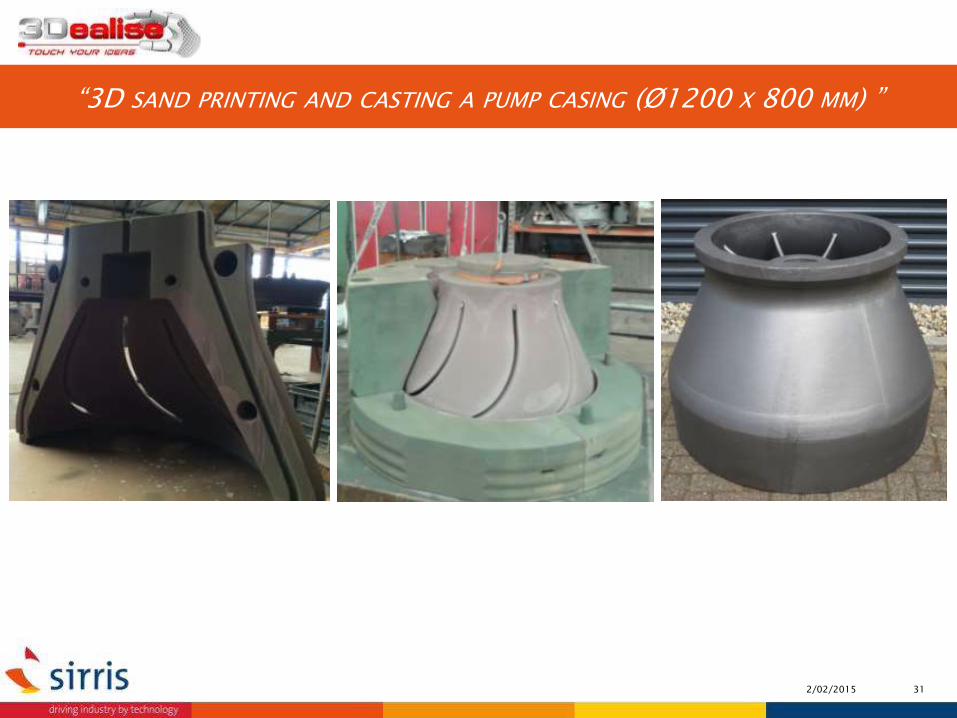
2/02/2015 31
“3D SAND PRINTING AND CASTING A PUMP CASING (Ø1200 X 800 MM) ”
MASTERCLASS “DESIGN FOR AM”

“ forget what you know
start from the function of the part
use as less material as possible
complexity for free ”
DESIGN FOR ADDITIVE MANUFACTURING
33

DESIGN CONSIDERATIONS COMPLEXITY
* Within the same bounderies 34

“Translating the desired design features into CAD geometry can be difficult
due to the increased part complexity.
Without good knowledge of the AM capabilities and CAD design,
this proces will be time consuming.”
DESIGN CONSIDERATIONS CHALLENGES
35

‣ available MATERIALS
‣ know the printer’s limitations
‣ HIGH PRICE of industrial machines
‣ CERTIFICATION of materials and technologies
‣ SURFACE QUALITY (supports, post-processing)
‣ QTY >< DIMENSIONS >< MATERIALS><PRICE
DESIGN CONSIDERATIONS THINGS TO CONSIDER LIMITATIONS
36

Protomold.co.uk
“A channel needs to be round”
DESIGN CONSIDERATIONS FORGET WHAT YOU KNOW
Psychology inertia: ‣ "the way that I am used to doing it." ‣ "You are not allowed to do that!" ‣ "Tradition demands that it be done this way!" ‣ "You have been given the information, and the information is true."
37

…part orientation
“the thicker the layer, the rougher the surface
the thinner the layer, the longer the build time”
…layer thickness
DESIGN CONSIDERATIONS BUILD TIME CAN BE INFLUENCED BY
38
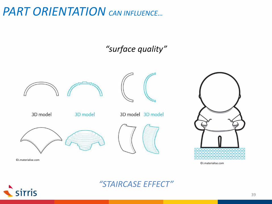
“surface quality”
©i.materialise.com
“STAIRCASE EFFECT”
PART ORIENTATION CAN INFLUENCE…
©i.materialise.com
39

40

“mechanical properties”
F F
F F
Note: only with SLS/FDM/SLA/LOM
PART ORIENTATION CAN INFLUENCE…
41
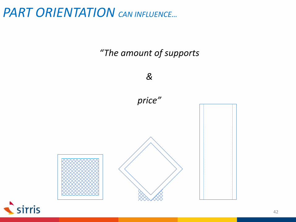
“The amount of supports
&
price”
PART ORIENTATION CAN INFLUENCE…
42
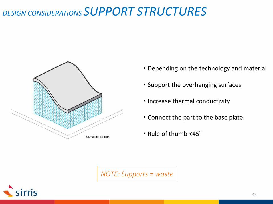
‣ Depending on the technology and material
‣ Support the overhanging surfaces
‣ Increase thermal conductivity
‣ Connect the part to the base plate
‣ Rule of thumb <45°
NOTE: Supports = waste
DESIGN CONSIDERATIONS SUPPORT STRUCTURES
©i.materialise.com
43

DESIGN CONSIDERATIONS SUPPORT STRUCTURES
44

© KULeuven © Layerwise
© makepartsfast.com
DESIGN CONSIDERATIONS SUPPORT STRUCTURES
45

‣ Same as build material (fused or non-fused)
‣ Second material
SUPPORT STRUCTURES MATERIAL
46


Reduce the thickness of your part to:
‣ Reduce the amount of material
‣ Reduce the risk of geometric deformations (with thermal technologies)
‣ Reduce the weight of your part
‣ Speed up the process
MATERIAL DO I NEED ALL THIS MATERIAL?
48

Source: i.materialise.com
DESIGN CONSIDERATIONS SPACE BETWEEN PARTS
‣ Keep sufficient space between separate parts.
‣ Gap size is technology specific
‣ Reference gap = 0,4mm
Source: i.materialise.com
49

Design the features of the part in function of the technology
‣ Wall thickness
‣ Size and orientation of holes
‣ Details like embossing and debossing
DESIGN CONSIDERATIONS FEATURE SIZE
©quickparts.com
©i.materialise.com
50

‣ Easy traceability
‣ Connect a label to your product
‣ Emboss / deboss the part number or name on your product itself
!! Design the tag size according to the production technology
DESIGN CONSIDERATIONS TAG YOUR PRODUCTS
©quickparts.com
©stratasys
51

CONCEPTS
CONCEPT GENERATION TRADE-OFF BETWEEN AM AND CONVENTIONAL
(re)DESIGN
DESIGN FOR AM KEY NOTE
VISIT 3D-PRINT LAB YOUR PRINTED PART
FUNCTION-DEFINITION
COMPANY SPECIFIC CASE IDEA GENERATION
AM IN GENERAL
TRENDS EN HYPES
BUSINESS MODELS
BASICS OF AM
DESIGN AND -INSPIRATIONTOOLS
DRIVERS FOR AM
DETAILS OF AM
SMART DESIGN FOR AM
DESIGN RULES EN CONSIDERATIONS
SOFTWARE TOOLS
ANALYSING PRINTED TOOLS
PREPARING .STL FILES
3D-PRINTING SOFTWARE
DA
Y 1
D
AY
2
DA
Y 3

Everyone who is involved in the design proces:
- R&D
- Production responsibles
- Designers
- Engineers
DATE 19-20th of may, 11th of june
LOCATION Malines and Liège
PRICE Sirris-members: € 2000 (excl. VAT)
Non-members: € 2495 (excl. VAT)
WHO SHOULD FOLLOW THIS MASTERCLASS?
PRACTICAL INFO


http://www.sirris.be
#sirris
http://www.linkedin.com/company/sirris
http://techniline.sirris.be