design detail standard sheets for concrete pavement · design detail standard sheets for concrete...
TRANSCRIPT
Technical Report Documentation Page1. Report No.FHWA/TX-07/0-5320-P2
2. Government Accession No. 3. Recipient's Catalog No.
5. Report DateAugust 2006Resubmitted: November 2006Published: March 2007
4. Title and SubtitleDESIGN DETAIL STANDARD SHEETS FOR CONCRETE PAVEMENTTRANSITION AREA
6. Performing Organization Code
7. Author(s)Youn su Jung and Dan G. Zollinger
8. Performing Organization Report No.Report 0-5320-P210. Work Unit No. (TRAIS)9. Performing Organization Name and Address
Texas Transportation InstituteThe Texas A&M University SystemCollege Station, Texas 77843-3135
11. Contract or Grant No.Project 0-532013. Type of Report and Period CoveredProduct
12. Sponsoring Agency Name and AddressTexas Department of TransportationResearch and Technology Implementation OfficeP. O. Box 5080Austin, Texas 78763-5080
14. Sponsoring Agency Code
15. Supplementary NotesProject performed in cooperation with the Texas Department of Transportation and the Federal HighwayAdministration.Project Title: Best Design and Construction Practices for Concrete Pavement Transition AreaURL: http://tti.tamu.edu/documents/0-5320-P2.pdf16. Abstract
Work under this task, “Design Detail Standard Sheets for Concrete Pavement Transition Area,” focused on thedevelopment of the transition detail sheets according to the transition types and locations identified under the task ofthe survey of best practices in accordance with Texas Department of Transportation (TxDOT) standards. Auto CAD isused to create the detail sheets from the analysis performed and the conclusions developed under the task of the designand construction transition guidelines for concrete pavement. These designs do not replace or supersede anypreviously used transition. The following 13 most frequently constructed types of concrete pavement transitions areintroduced and some have optional alternative designs.
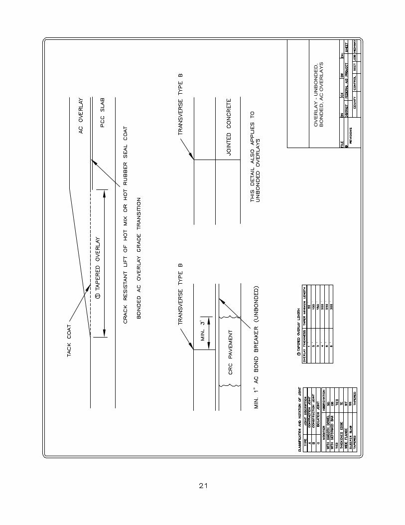
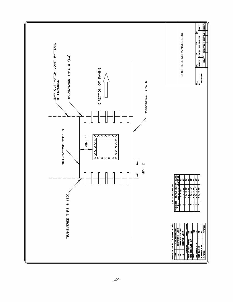
1. Continuously Reinforced Concrete (CRC) Pavement to CRC Pavement Thickness Transition.2. CRC Pavement to CRC Pavement Construction Joint Transition.3. CRC Pavement to Jointed Concrete (JC) Pavement Transition.4. CRC Pavement to Flexible Pavement Transition.5. JC Pavement to Flexible Pavement Transition.6. JC Pavement to JC Pavement Transition.7. CRC Pavement to Bridge Approach Slab Transition.8. JC Pavement to Bridge Approach Slab Transition.9. Intersection Transition.10. Overlay-Unbonded, Bonded, Asphalt Concrete (AC) Overlays Transition.11. CRC Bonded Overlay to CRC Pavement Transition.12. Drop Inlet/Drainage Box.13. Ramp/Gore Area Transition.The sketches of the transition details are checked for consistency with the guidelines. The transition detail
sheets will be evaluated by TxDOT for implementation.17. Key WordsConcrete Pavement, Transition Area, Joint, Design,AutoCAD
18. Distribution StatementNo Restrictions. This document is available to the publicthrough NTIS:National Technical Information ServiceSpringfield, Virginia 22161http://www.ntis.gov
19. Security Classif.(of this report)Unclassified
20. Security Classif.(of this page)Unclassified
21. No. of Pages34
22. Price
Form DOT F 1700.7 (8-72) Reproduction of completed page authorized

DESIGN DETAIL STANDARD SHEETS FOR CONCRETEPAVEMENT TRANSITION AREA
by
Youn su JungGraduate Assistant Research
Texas Transportation Institute
and
Dan G. ZollingerAssociate Research EngineerTexas Transportation Institute
Product 0-5320-P2Project 0-5320
Project Title: Best Design and Construction Practices for Concrete Pavement TransitionArea
Performed in cooperation with theTexas Department of Transportation
and theFederal Highway Administration
August 2006Resubmitted: November 2006
Published: March 2007
TEXAS TRANSPORTATION INSTITUTEThe Texas A&M University SystemCollege Station, Texas 77843-3135


v
DISCLAIMER
The contents of this report reflect the views of the authors, who are responsible
for the facts and the accuracy of the data presented herein. The contents do not
necessarily reflect the official view or policies of the Federal Highway Administration
(FHWA) or the Texas Department of Transportation (TxDOT). This report does not
constitute a standard, specification, or regulation. Its contents are not intended for
construction, bidding, or permit purposes. The use and names of specific products or
manufacturers listed herein does not imply endorsement of those products or
manufacturers. The engineer in charge of the project was Dan G. Zollinger, Texas P.E.
#67129.

vi
ACKNOWLEDGMENTS
This project was conducted in cooperation with TxDOT and FHWA. The authors
wish to express their appreciation to the Federal Highway Administration and the Texas
Department of Transportation personnel for their support throughout this project, as well
as the project coordinator, Charles Gaskin, P.E.; project director, Hua Chen, P.E.; and
members of the project monitoring committee: Sage Diller; Darlene Goehl, P.E.; John
Holt, P.E.; Larry Buttler, P.E.; and Hal Stanford, P.E.

vii
TABLE OF CONTENTS
Page
1. CRC Pavement to CRC Pavement (Thickness Transition)............................................ 1
2. CRC Pavement to CRC Pavement (Header Joint - Option 1) ....................................... 2
3. CRC Pavement to CRC Pavement (Header Joint - Option 2) ....................................... 3
4. CRC Pavement to Jointed Concrete Pavement (Option 1) ............................................ 4
5. CRC Pavement to Jointed Concrete Pavement (Option 2) ............................................ 5
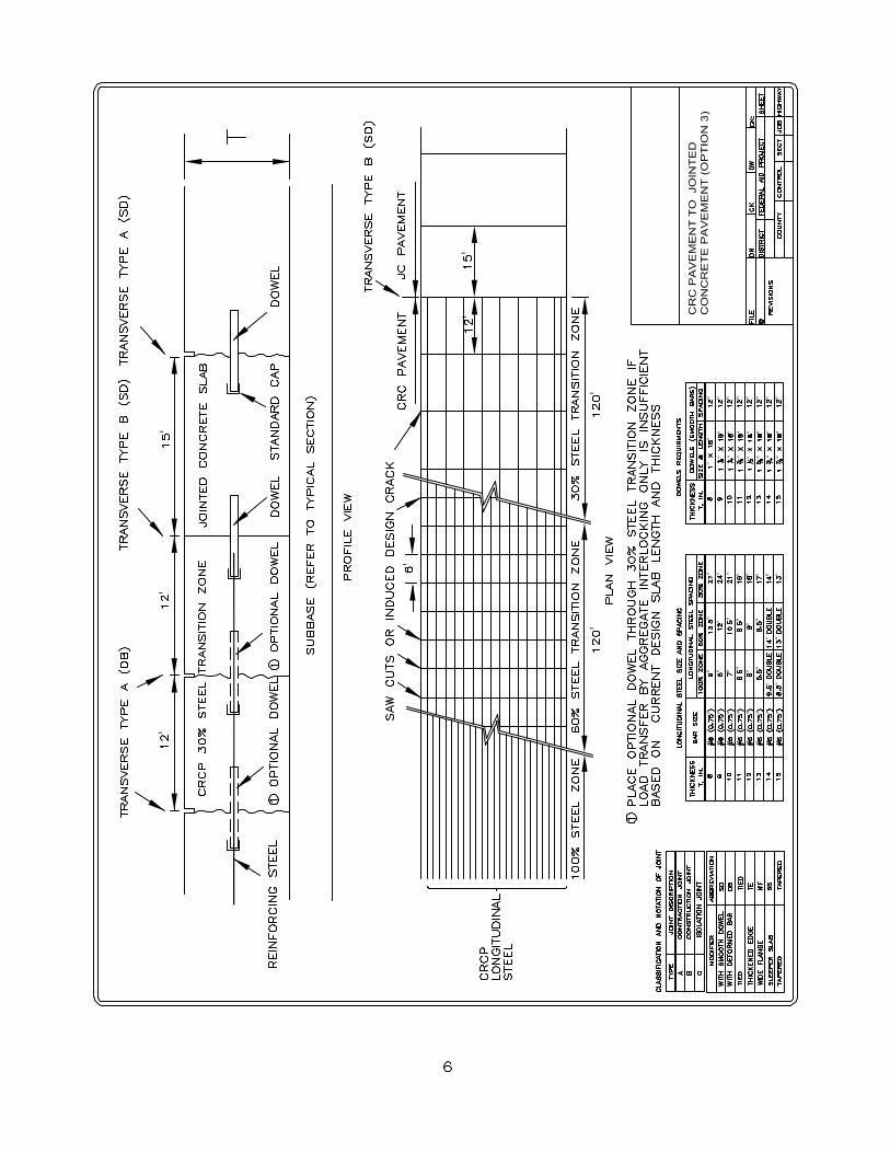
6. CRC Pavement to Jointed Concrete Pavement (Option 3) ............................................ 6
7. CRC Pavement to Flexible Pavement (Option 1 - Sleeper Slab)................................... 7
8. CRC Pavement to Flexible Pavement (Option 1 - Wide Flange) .................................. 8
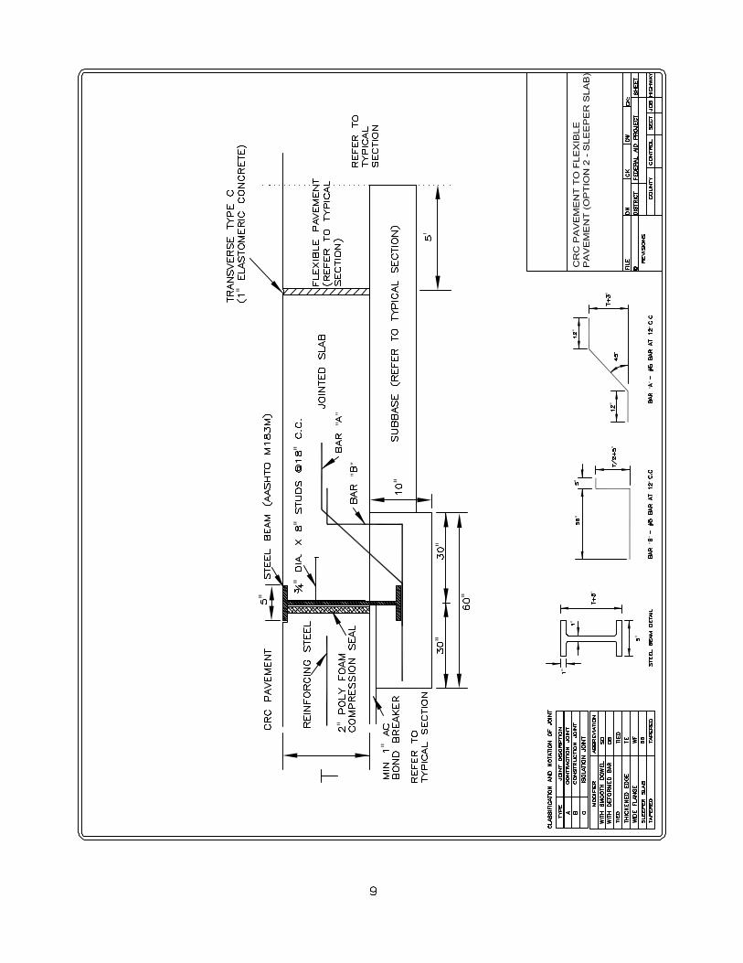
9. CRC Pavement to Flexible Pavement (Option 2 - Sleeper Slab)................................... 9
10. CRC Pavement to Flexible Pavement (Option 2 - Wide Flange) .............................. 10
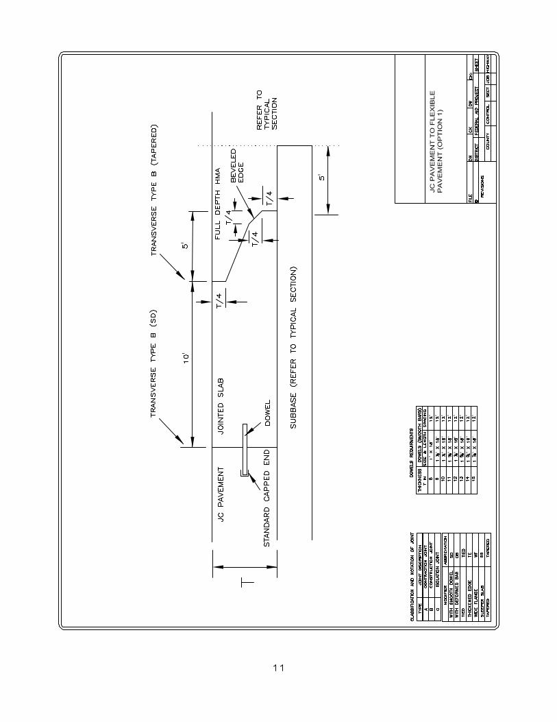
11. JC Pavement to Flexible Pavement (Option 1).......................................................... 11
12. JC Pavement to Flexible Pavement (Option 2).......................................................... 12
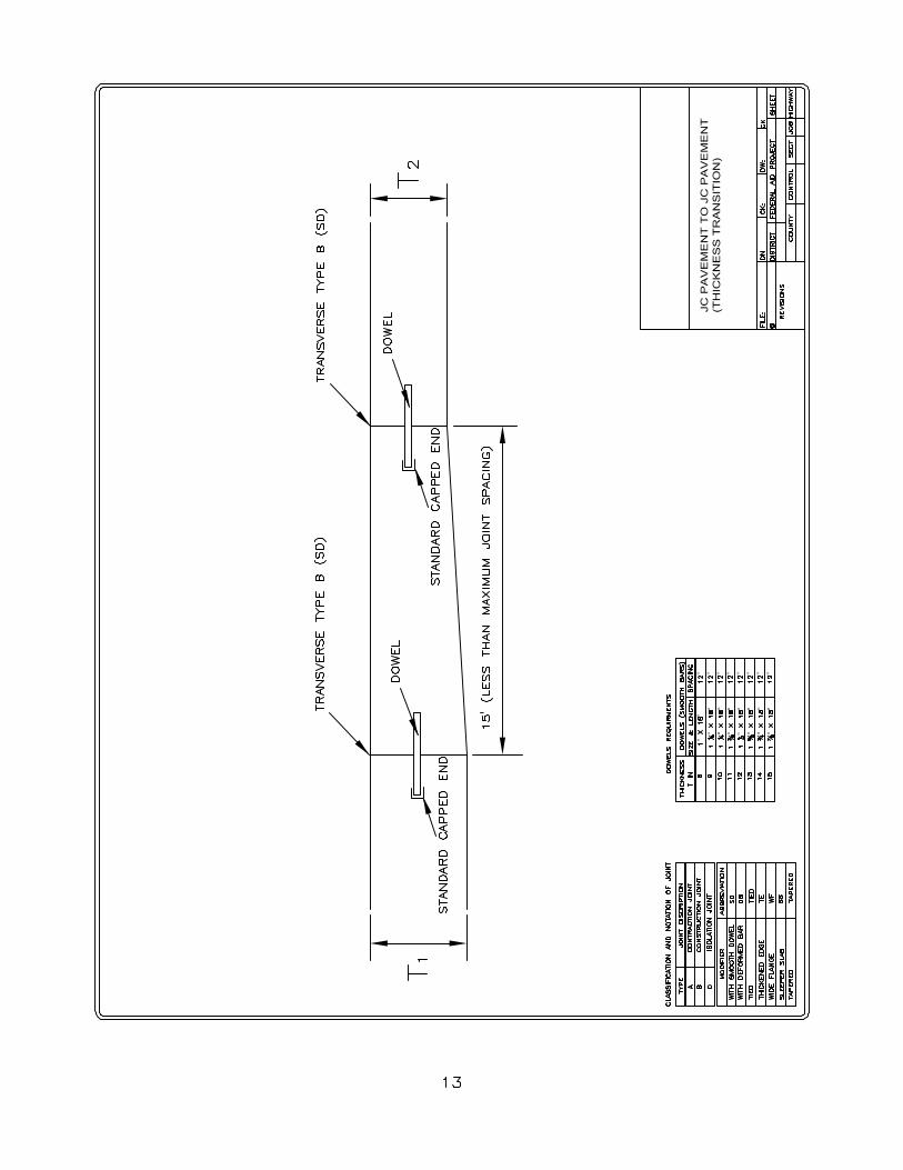
13. JC Pavement to JC Pavement (Thickness Transition) ............................................... 13
14. CRC Pavement to Bridge Approach Slab (Option 1) ................................................ 14
15. CRC Pavement to Bridge Approach Slab (Option 2) ................................................ 15
16. CRC Pavement to Bridge Approach Slab (Option 3) ................................................ 16
17. JC Pavement to Bridge Approach Slab...................................................................... 17
18. Intersection (Option 1 - Joint Distance > 500 ft) ....................................................... 18
19. Intersection (Option 2 - Joint Distance < 500 ft) ....................................................... 19
20. Intersection (Option 3)............................................................................................... 20
21. Overlay - Unbonded, Bonded, AC Overlays ............................................................. 21
22. CRC Bonded Overlay to Single-Layered Steel CRC Pavement................................ 22
23. CRC Bonded Overlay to Double-Layered Steel CRC Pavement .............................. 23
24. Drop Inlet/Drainage Box............................................................................................ 24
25. Ramp/Gore Area Transition....................................................................................... 25