design criteria for usu stilling basin pipe flow to open channels.pdf
TRANSCRIPT
Utah State UniversityDigitalCommons@USU
All Graduate Theses and Dissertations Graduate Studies, School of
1-1-1968
Design Criteria for USU Stilling Basin Pipe Flow toOpen ChannelsChi-Yuan Wei
This Thesis is brought to you for free and open access by the GraduateStudies, School of at DigitalCommons@USU. It has been accepted forinclusion in All Graduate Theses and Dissertations by an authorizedadministrator of DigitalCommons@USU. For more information, pleasecontact [email protected].
Recommended CitationWei, Chi-Yuan, "Design Criteria for USU Stilling Basin Pipe Flow to Open Channels" (1968). All Graduate Theses and Dissertations.Paper 2924.http://digitalcommons.usu.edu/etd/2924
DESIGN CRITERIA FOR USU STILLING BASIN
PIPE FLOW TO OPEN CHANNELS
by
Chi-Yuan Wei
A thesis submitted in partial fulfillment o f the requirements for the degree
of
MASTER OF SCIENCE
in
Civil Engineering
Utah State University Logan, Utah
1968
ACKNOWLEDGMENTS
The study was conducted at the Utah Water Research Laboratory,
College of Engineering, Utah State Univers ity . The writer wishes to
express his gratitude to Dr. Gordon H. Flammer for his supervision
and adv ice during the initial studies which optimized the design of the
dissipator pipe.
The writer wishes to express his deep appr e ciation to Prof.
Gaylord V . Skogerboe for taking over the supervision of the study when
Dr. Flammer took leave from USU to teach at the SEA TO Graduate
School of Engineering at Bankok, Tha iland. Prof. Skoger boe super
v ised the studies which optimized the design, or dimensions , of the
stilling basin structure. The final design resulted from his valuable
recommendations and his constant encouragement, and it is hereby
gratefully acknowledged .
Appreciation is also extended to the shop personnel, Ken Steele
and Gilbert Peter son, for c onstruc ting the variable -dim ens ion stilling
basin structure. Thanks are also due to Mrs. Donna Falkenborg for
editing the thesis.
Chi - Yuan Wei
TABLE OF CONTENTS
Introduction 0
Review of Literature 0
Hydraulic jump basin 0
Free-jet stilling basin Free-jet chutes 0
Hump stilling basin Jet diffusion and impact stilling basin Jet diffusion stilling basin 0
Contra Costa energy dissipater Impact stilling basin o
Manifold stilling basin
Experimental Design o
Theory of jet diffusion Dimensional analysis.
Design of Dissipater Pipe
Equipment o
Experiments
Design of Stilling Basin 0
Model basin Experimental design Width of still ing basin Length of s ti lling basin Tailwater elevation. Design example
Summary
Literature Cited
Vita o
iii
3
4 7 8 8 9 9
II 12 13
17
17 23
25
25 27
30
30 34 35 35 42 46
5 1
53
55
Figure
.2
3
4
5
6
7
8
9
10
II
12
13
14
15
16
LIST OF FIGURES
Hydraulic jump in horizontal channels
Free -j et chute basin
Hump stilling basin
Enders Darn outlet works stilling basin •
The C ontra Costa energy dissipater
Impact stilling basin design •
General layout of the manifold stilling basin
Schematic repre sentation of jet d iffusion
The model basin •
The arrangement of the short-pipe energy dissipater , the inlet pipe, and the stilling basin (first model) .
The recording system and the flow pattern in the stilling basin (firs t model )
Top view and side view of the still ing basin
The general layout of t he stilling basin
The inside view of the s t i lling basin •
Comparisons of stilling basin performances at different w idth ratios . (F I= 2 . 80, D /D
1 = 2 . 0, L/D 1 = I. 0, W/
D1
= 0. 5 , Y /Db= I. 5 , Y2
tD1
= 3. 0, Lb/D 1 = 2. 0, d/ D
1 =!. 54, and
1 = 3 . 25 1nches) .
Comparison of flow patterns at different stilling basin length ratios for a low Froude number (F
1 = 2. 8, D2 /
D1
= 2 . 0, L / D1
= 1.0, W/D1
= 0.5, Y /DI = 1. 5 , WblD 1 = &. 67, and n
1 = 3 .2 5 inches). . ••
Page
7
8
9
10
II
12
14
18
22
26
28
3 1
32
33
36
38
17 Effect of tailwater depth on still ing basin performance at a h igh Froude number (Lb/D = 2. 0, F = 7 . 7, D /D = 2. 0, L/D
1 = 1.0, W/D
1 = 0 . 5 , Y//D
1 = !. 5,
1Wb /D 1 =1,.77, D 1
= 3. 2 5 inches). 40
iv
Figure
18
19
20
LIST OF FIGURES (C ontinued )
Comparison of stilling basin performances at different len~th ratios fo~ a h1gh Frou~e number (~ = 7. 7, D2 I D
1- 2 . 0 , L/D
1- l. 0, W/D
1- 0. 5, Y/ D 1- 1. 5, Wb/
D1
= 6. 77, d/D1
= I. 54, and u1
= 3. 25 1nches) . .
Comparison of stilling basin performances at different open channel elevation s (F
1 = 3. 50 , D
2/D
1 = 2. 0 , L/D
1 = 1.0, W/D
1 = 0 . 5, Y /D
1= 1. 5, W / D
1 c 4.0, Lb/D
1=
2. 0 and D1
= 6 inche s)1
. b
Schematic profiles of the flow patterns at different
Y2/n
1_rat ios (D
1 =_6 inches, F= ~.50, D 2 / D 1 ~ 2 .0
LtD1
- l.O , W/D1
- 0.5, Y/D1
- 1. 5 , T/Dz- 1.5, D
1 = 2. 0 ) . . . . . . . . . . . . . ....
Page
4 1
43
2 1 Comparison of stilling basin performances at different
~ailwater dep~h ratios with_Y2 /D 1 = 1.5 ~~ = 4.7, D /~ 1 - 2. 0 , L/D
1 .. 1. 0, W/D
1- cr. 5, Y /D 1 - 6. 77, Lb/ D 1-
3.3, and D1
= 3.25 mches) ...... . . . ... 45
22 Relationship between boil height and Froude number 47
23 De sign example of USU stilling basin 50
v
b
d t
g
H
L
n
Q m
NOMENCLATURE
Definition
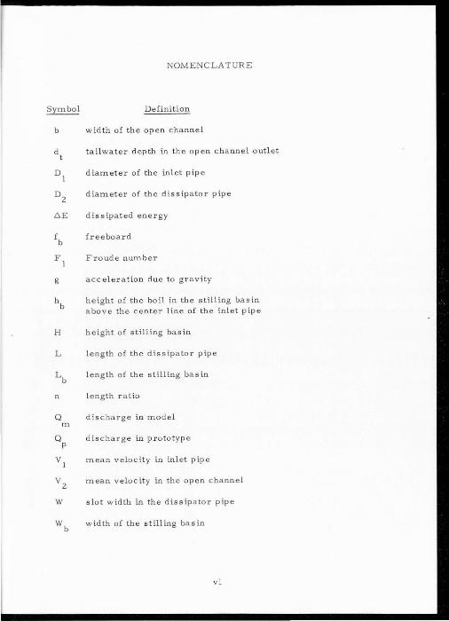
width of the open channel
tailwater depth in the open c h a nnel outlet
diamete r of the inlet pipe
diameter of the dissipater pipe
diss ipated energy
freeboard
Froude number
acceleration due to gravity
height of the boil in the stilling basin above the center line of the inlet pipe
height of stilling basin
length of the dissipater pipe
length of the stilling bas in
length ratio
dis c harge in model
Qp d is charge in prototype
v1
mean velocity in inl et pipe
V 2
mean velocit y in the open channel
W slot width in the dissipater pipe
wb width of the stilling basin
vi

NOMENCLATURE (Continued )
Definition
e levation of the inle t pipe above the bottom of the stilling basin
elevation of the open channel above the center line of the inle t pipe
any length dimension
vii
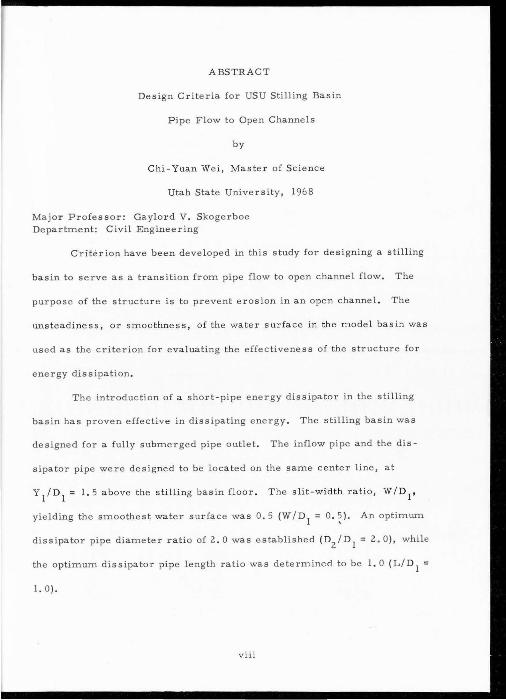
ABSTRACT
Design Criteria for USU Still ing Basin
Pipe Flow to Open Channels
by
Chi-Yuan Wei, Master of Science
Utah State University, 1968
Major Professor: Gaylord V. Skogerboe Department: Civil Engineering
Criterion have been developed in this study for designing a stilling
basin to serve as a transition from pipe flow to open channel flow. The
purpose of the structure is to prevent erosion in an open channel. The
uns teadiness , or smoo thness, of the water surface in the model basin was
used as the criterion for evaluating the effectiveness of the structure for
energy dissipation.
The introduction of a short-pipe energy dissipater in the stilling
basin has proven effective in dissipating energy . The stilling basin was
designed for a fully submerged pipe outlet. The inflow pipe and the dis-
sipat or pipe were designed to be located on the same center line, at
Y 1
/ D1 = l. 5 above the stilling basin floor. The slit-width ratio, W/D
1,
yielding the smoothest water surface was 0. 5 (W/D1
= 0 . ~) . An optimum
dissipater pipe diameter ratio of 2. 0 was established (D2/n
1 = 2. 0 ), whil e
the optimum dissipater pipe l ength ratio was determined to be l. 0 (L/ D 1 =
I. 0 ).
viii
Three diameters of inlet pipe were used to determine scale effects.
Within the accuracy of the measurements used in this study , no scale effects
were detected.
The expanding characteristics of a submerged jet were used in
e stablishing the length of the stilling basin . Based on the dissipator
pipe diameter ratio of 2. 0 (D2
tn_1
= 2. 0 ), the stilling basin length
ratio is 3. 5 (Lb /D1
= 3. 5 ) .
Relations among the tailwater depth (dt), the outlet flume
floor elevat ion (Y2
). the height of boils in the stilling basin (hb),
the width of the stilling basin (Wb), and the amount of freeboard,
fb, have been studied. The interrelationships among F 1, (Y2 + dt)/
D1
, Wb/D1
, and fb/D 1
have been shown graphically.
INTRODUCTION
To prevent possible erosion below ove rflow spillway s, c hutes,
a nd sluices, excess kinetic energy in flowing water needs to be dis-
s ip a ted in either a vertic a l or horizon ta l direction, or both. In a
horizontal direction the ener gy may be dissipated by shea r drag,
pressure drag, or an inc rease in p iezometric head. In the ver tical
direction the energy may be dissipated by diffusion of j ets v ertically
upward or by diffusion of jets vert ically downward.
The ene rgy dissipator under study is designed a s a trans itio n
from pipe flow to open channel flow. Energy diss ipation is performed
in both the vertical and horizontal d irec tions by shear drag, pressure
d r ag , and vertical diffusion as the major mechanisms in dissipating
the excess energy in the flow.
The study wa s made under the following cond itions :
1. The pipe outlet wa s fully submerged.
2. The inflow pipe and the diss ipato r pipe had the sam e cent er
line, and were parallel to the open channel bed.
3 . The inflow pipe was th e onl y sourc e of flow t o the open
channel.
4 . The di ssipator p ipe wa s self -cleaning .
5 . Structural features, shape, and dimension s were determined
by model studies.
T he two important compo nents in the design of the energy d issipator
2
are the dissipator pipe and the stilling basin (i.e., the depth, w idth,
length, and shape of the stilling basin). To find the best design for a
stilling basin involving a short-pipe dissipator, the unsteadiness or the
smoothness of its water surface was us ed as the criterion for evaluating
the effectiveness of varous sizes and lo cat ions of the short-pipe dissipator
and the relative dimensions of the stilling basin.
The energy dissipator under study is an impact-type dissipator
which requires a relatively small basin. This structure is an effective
and economical means of providing a transition from full pipe flow to open
channel flow. Unless the kinetic energy of the high velocity jet issuing
from the pipe is dissipated within a rigid boundary structure, erosion
of the open channel bed and large surface waves would result. A sa tis
factory energy dissipator is necessary to minim ize channel erosion
and stabilize the free surface wave fluctuations.
The energy dissipation results from the submerged jet im
pinging upon a short-pipe energy dissipator and then being turned on
itself, along with part of the jet being turned downward through the
slot in the bottom of the dissipator pipe . The energy of the flowing
water is dissipated by the diffusion of the jet from the inlet pipe into
the stilling basin and the shearing act ion between the jet itself and the
water surrounding it.

3
REVIEW OF LITERATURE
Energy dissipation in some form has been a part o f many
hydraulic structures throughout the world where the destructive energy
in flowing water must be brought under control. Most of lhe energy
dissipators have performed their intended function adequately. Those
that received the benefit of model tests have functioned particularly
well. Except in unusual circumstances, only larger structures are
subjects of individual model studies. However, there a re some smaller
structures that have been subjected to preliminary model studies to
meet pa rticular and rigid requirements.
Although hundreds of stilling basins and energy dissipator
devices have been designed in conjunction with spillways, outlet works,
a nd canal structures, it is often necessary to make model studies of
individual structures to be certain that these structures will operate
as anticipated. The reason for these repetitive tests is that a factor
of uncertainty exists regarding the overall performance characteristics
of energy dissipators. In important projects, such as those involving a
large number of stilling basins, generalized designs for the basins
are often necessary for economy and to meet specific requirements .
These designs can be developed by model inve stigations. The basins
thus designed are usually provided with special appurtenances, including
c hute blocks, s ills, and baffle piers.
4
Existing energy dissipator designs are classified as one or a
combination of the following types: , (a ) roughened channel lining (Bradley
and P eterka , 1957), (b) drop structure basin (Beichill, 1956). (c) free fall
basin (Gne lton, Weingaertner, and Sevin, 1953), (d) hydraulic jump basin
(Elevatorski, 1959, and Chow, 1953), (e ) diffuser structure (Elevatorski,
1959, and Fiala, 1961). (f) impact structure (Elevatorski, 1959~ Keirn,
1962; and Peterka, 1957), (g) r o ller bucket (Bradley and Peterka, 1957),
and (h) flip bucket (Elevatorski, 1959).
Hydraulic jump basin
Utilization of the hydraulic jump, whenever possible, to dissipate
energy has been an accepted pract ice. The hydraulic jump is d e fined as
the sudden and turbulent passage of water from a low stage below critical
depth to a high stage above critical depth during which the velocity changes
from supercritical to subcritical. The jump is accompanied by violent impact
and consists of an abrupt rise of the water surface in the region of impact
between the rapidly moving stream and the slowly moving water. The water
surface at the beginning of the abrupt rise is constantly falling against the
oncoming stream, which is moving at a high ve locity.
Th e theory of the hydraulic jump was developed in early days for
horizontal slightly inclined channels in which the weight of water in the
jump has little effect upon the jump behavior and hence is ignored in
the analysis. The results thus obtained, however, can be applied to most
channels encountered in engineering problems. For channels of la rge slope,
the weight effect of water in the jump may become so pronounced that it
must be included in the analysis.
..
A hydraulic jump will form in the channel if the Froude number
F 1
of the flow , the flo w dep th y 1
, and a downstream depth y 2 satisfy
the equation
2 (1)
That is , for supercritica l flow in a horizontal rectangular channel
the resistance along the channel bed results in a d ecr ease in veloctty
and an increase in depth in the direction of flow.
A hydraulic jump occur ring on a horizontal floor can be
cla ssified into several distinct types . Accord ing to the studies of the
U S . B urea u of Reclamat ion (1958), these types can be conven t e ntl y
classified according to the Froude number , F 1
, of the incoming flow
as follow:
l .
2
3 .
4 .
5 .
An undular jump for F 1
= I to I . 7 .
A weak jump for F1
=I 7 to 2 . 5 .
An oscillatmg jump for F 1
= 2 . 5 to 4 5.
A steady jump for F 1
4 . 5 to 9 ·. 0 .
A strong jump for F 1
9 . 0 and larg er .
A steady jump is well-ba l anced and the performance is a t its
best The energy dissipation ranges from 45 to 70 percent . The jump
a ct10n of a strong jump is rough, but effective, since the energy dts
sipa tion may reach 85 percent.
The loss of energy in the jump is equal to the difference in
specific energies beforea.nd.after the jump . It can be shown tha t the
5
6
loss is
(2)
The ratio of the s pec ific energy after the jump to that before
the jump is def ined a s the efficienc y of the jump, t hat i s
+ 1 (3)
SF~ (2
The equation indic ates that the efficiency of a jump is a dimen sion-
less function, depending only on the Froude numbe r of the a pproac hing
flow.
From a pract ical v i ew p oint , the h ydraul ic jump i s a useful
means of dissipatin g exc ess energy in supercritical flow. Is medt
is in pre v enting possible erosion below overflow spillwa y s , c hutes ,
sluic es , and other hydrau lic structures, for it quic kly reduc es t he
v elo c i ty of the flow on a pav ed apron to a point where the flow becomes
incapa ble of s c ouring the dow s r e am c h annel bed.
The use of the h ydraulic jump fo r e ergy diss ipation is u s ually
c onfined partl y or entir ely to a channel r eac h t h at i s know n as the
stilling basin. The bo t tom of the basin is pa v ed to r e s is s c o uring.
In practice, the stilling basin is seldom design ed to confine the e n ire
length of a f ree hydrau lic jump on the paved ap r on, because s uch a
basin would be too expen s ive. Con sequ e n tly , ac c esso ries to c o trol
he jump ar e u s ually in stalled in the basin . The main purpo se of s u c h
c ontrol is to shorten the length of c hannel whe re the jump wi ~l
7
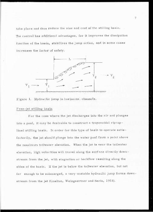
take place and thus reduce the size and cost Q[ the stilling basin.
The co ntrol has additional advantages, for it improves the dissipation
function of the basin, stabilizes the jump action, and in s ome cases
increases the factor of safety .
r-L I
y2
VI -- _::- -1 /?J))) t)) ~),)J>))J/)))))) ;;;;;; ..- >>J))/7))/J
Figure I. Hydraulic jump in h ori zonta l c hanne l s.
Free-jet stilling basin
For the ca se where the jet discharges into the air and plunges
into a pool, it may be desirable to construct a trapezoidal rip.,.ap-
lined stilling basin. In order for this type of basin to operate satis -
factorily, the jet should plunge into the water pool from a point above
t he maximum tailwate r elevation. When the jet is near the tailwater
elevation, high velocitie s will travel along the surf ace d irectly down-
st r eam from the jet , with stagnat ion or backflow re s ulting along the
sides of the bas in . lf the jet is below the tailwater ele vation, but not
far enough to be submerged, a v e ry unstable hydraulic jump forms down -
stream from the jet (Gnelton, Weingaertner and Serin, 1953) .
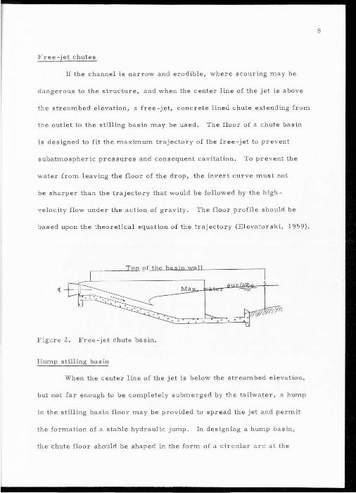
Free-jet chutes
If the channel is narrow and erodible, whe re s couring may be
dangerous to the structure, a nd when the center line of the jet is above
the streambed elevation, a free -jet, concrete lined chute extending from
the outlet to the stilling basin may be used . The floo r of a c hute basin
is designed to fit the maximum trajectory of the free -jet to prevent
subatmospheric pressures and consequent cavitation . To prev e n t the
w a ter from leav ing the floor of the drop, the invert c urve must not
be sharper than the trajectory that would be followed by the high
v elocity flow under the action of gravity. The floor profile sho)lld be
based upon the theoretical equation of the trajectory (Elevator ski , 1959 ).
Figu re 2. Fr ee- jet chute basin.
Hump stilling bas in
When the c enter line of the jet is below the streambed eleva tion,
but not far eno ugh to be completely submer ged by the tailwater , a hump
in the stilling basin floor may be provided to spread the jet and permit
the fo r m a tio n of a stable hydraulic jump. In designing a hump basin,
t he chute floor should be shaped in the form of a circular arc at the
8
9
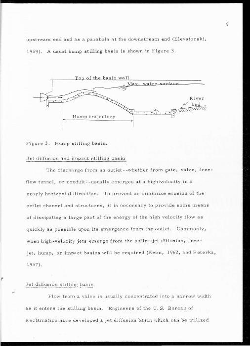
upstream end and as a parabola at the downstream end (Elevatorski,
1959). A usual hump stilling basin is shown in Figure 3.
basin wall M
Hump trajectory
Figure 3. Hump st.ill.ing basin.
Jet diffusion and impact stilling basin
The discharge from an outlet--whether from gate, val e, free-
flow tunnel, or conduitC-usually emerges at a hi'gh ivelocity in a
nearly horizontal direction. To prevent or minimize erosion of the
outlet c hannel and structures, it is nec essary to provide some means
of dissipating a large part of the energy of the high v elocity flow as
quickly as possible upon its emergence from the outlet. Commonly,
when high-velocity jets eme rg e from the outlet-jet diffusio n, free-
jet, hump, or impact basins will be required (Keim, 1962, and Peterka,
1957) .
f Jet diffusion stilling bas w
Flow from a valve is usually concentrated into a narrow width
as it enters the stilling basin. Engineers of the U.S. Bureau of
R eclamat ion have developed a jet diffusion basin which can be utiliz d
10
to reduce the length of ba sin normally required by a h ydraulic jump.
Experiments indicated tha t s ati s factory results could be obta ined by
direct ing the jets sharply towa rd the bottom, rather than over the t a il-
water surfac e. It was fo und nec essary to protec t the inflow water with a
hood, or some other device, until it w a s con siderably beneath the tail-
water surface . A d eflector hood pre ve n ted the jet from being torn
apart b y induced eddies until i t was well submerged, thereby accom-
p lish ing energy dissipation in a Jess vio lent and more efficient m anner.
It is believed tha t t he effective n ess of th is method is due to the small
grain turbulence which is created in the basin. Becaus e the outflow
is well prote c ted un til submerged , it still contains suHicient
energy to produc e many small, efficient, energy dissipating eddies
at the bottom of the basin . From a theore tica l stan dpoint, it has been
proven that a large num ber of smail eddies are mo r e effic ien in dis -
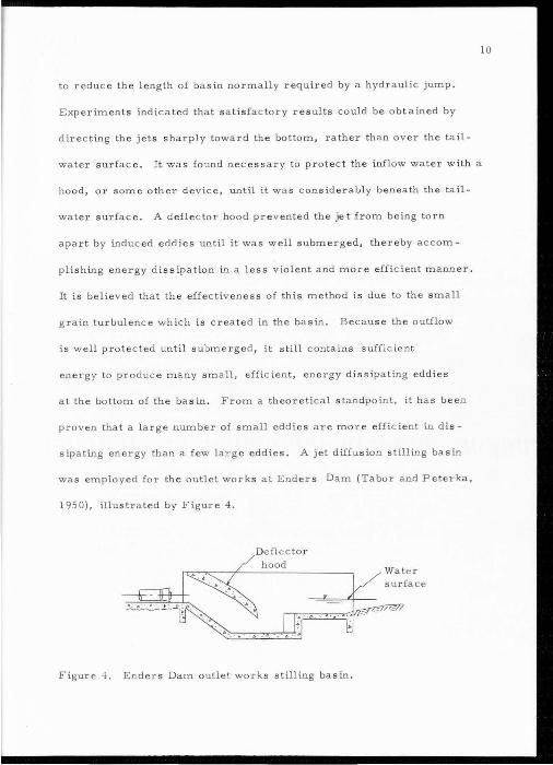
sipating energy than a few lar ge eddies. A jet diffu sio n s till ing basin
was employed for the outlet works a t Ender s Dam (Tabor and Peterka ,
1950), illustra ted by Figur e 4 .
Deflector hood
Figure 4. Ender s Dam outle work s stilling basin.
II
Contra Costa energy dissipator
The Contra Costa energy dissipator was developed in 1956 at
the Fluid Mechanic Laboratory of the University of California, Berkeley
(Keirn, 1962). The dissipator is for use in the reestablishment of natural
channel flow conditions at culvert outfalls where there are uncontrolled,
excessively high, effluent v elocities at depths less than half the culvert
diameter . .
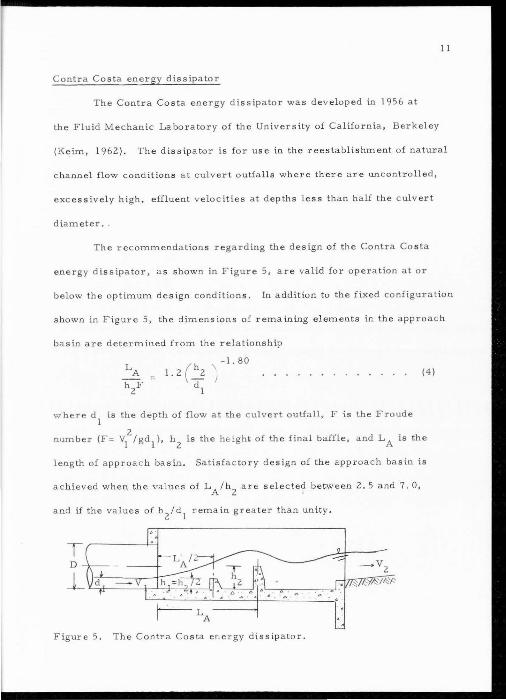
The recomm endations regarding the design of the Contra Costa
energ y dissipator, as shown in Figure 5, are valid for operation a t or
below the optimum design conditions. In addition to the fixed configuration
shown in Figure 5, the dimensions of rema ining elements in the approach
basin are determined from the relationship
(4)
w here d1
is he dep h of flow at the cul vert outfall, F is the F r oude
2 number (F = v
1 I gd
1 ), h
2 is th e height of the final baffle, and LA is the
length of approa c h basin . Satisfac tory design of the approach basin is
achieved when the values of L A/h2
are selected between 2. 5 and 7. 0,
and if the value s of h2
/d1
r emain g r eater than unity .
Figur e 5. The Contra Costa en e r gy dissipator.
Impact stilling basin
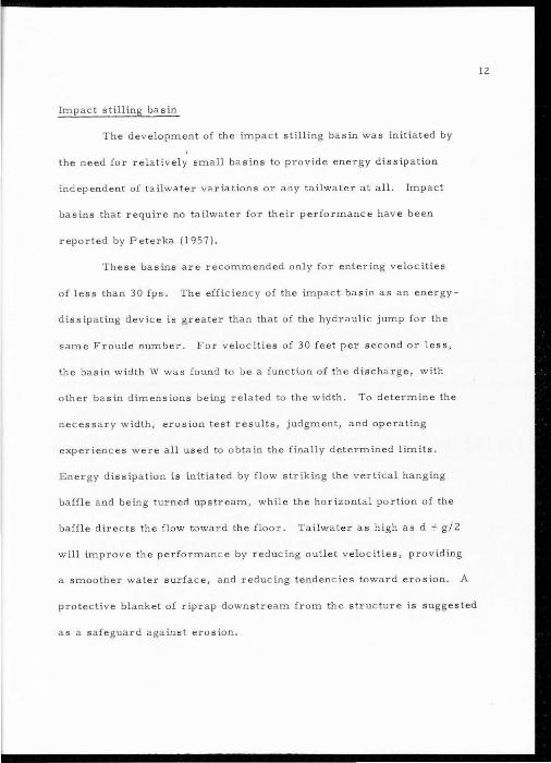
The development of the impact st illing bas in was initiated by
the need for rela ti vely small basins to prov ide energy diss ipa tion
independent of tailwater variations or any tailwat e r a t all. Impact
basins that require no tailwater for their performance hav e been
reported by Peterka ( 1957).
These basins are recommended only for e ntering velocities
of less than 30 fps. The efficiency of the impact ba s in as an energy
dissipating device is greater than that of the hydraulic jump for the
same Froude number. For velocities of 30 feet p er s econd or less,
the basin width W was found to be a function of the disc harge, with
other basin dimensions being related to the w idth. To determine the
necessary width, erosion test results , judgment, and operating
experiences were all used to obtain the finally determined limits.
Energy dissipation is initiated by flow striking the vertical hanging
baffle and being turned upstream, while the horizontal portion of the
baffle directs t h e flo w toward the floor. Tailwa te r a s h igh as d + g/2
will improve the performance by reducing outl et v e locities, providing
a smoother water surface, and reducing tendencies toward erosion. A
protective blanket of riprap downstream from the s ructure is suggested
as a safeguard against erosion.
12
13
- b.. . ~ .o •• ~. -_
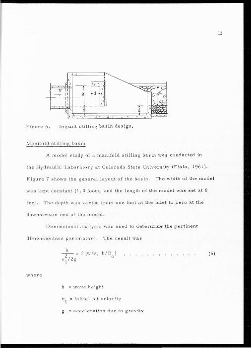
Figure 6. Impact stilling basin design.
Manifold stilling basin
A model study of a manifold stilling basin wa s conducted in
the Hydraulic Laboratory at Colorado State Univer sity (Fia la, 196 1) .
Figure 7 shows the general layout of the basin. The width of the model
was kept constant (1. 0 foot), and the length of the model was set at 8
feet. The depth was varied from one foot at the inlet to zero at the
downstream end of the model.
Dimensional analysis was used to determine the pertinent
dimensionless param eters . The result was
(5)
where
h = wave heigh
v1
= initial jet velocity
g = acceleration due to gravity
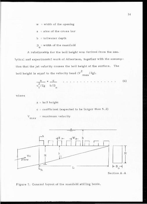
w = width of the opening
s size of the cross bar
b tailwater depth
B = width of the manifold 0
A relationship for the boil height was derived from the ana-
lytical and experimental work of Albertson, together with the as sump-
tion that the jet velocity causes the boil height at the surface. The
boil height is equal to the velocity head (V2
/ 2g). max
where
a 2
v1
/2g
c
b/B 0
a boil height
(6)
c coefficient (expected to be l a rger than 5.2)
V max = maximum velocity
Of S ect ion A -A
Figure 7 . General layout of the manifold stilling basin .
14
Equation 6 represents a manifold stilling basin with numerous
jets. However, two limiting conditions were cons idered:
I. For low tailwater, a very small amount of tailwater inter-
ference was present and the data indicated that V max/v 1 a pproached
unity for low values of w/s.
2. For high tailwater and/or large value s ofw/s, the mani-
15
fold behaved as one large jet, and a s sumin g c onstant-'ih'fi'Ow' arid moml!Tttum
flux per1y.nit ·ln'-ea is the sam~ -whether the flow is coining·tht..ough n 1
where
n B I o
n1
= number of slots
Extensive laboratory investigations were conducted, and the validity
of the above equation was verified experimentally.
Significant results obtained from these model studies are:
(7)
I. The best velocity and pressure distributions were obtained
by using square inlet sections.
2. As b/s decreases to about 5, v/v0
becomes smaller.
3. As w / s increases, v1/v
0 becomes smaller.
4. Equation 6 was pro v en to be valid for values of c greater
tha n 5. 2 .
16
5. As w/s becomes larger, the behavior of the manifold
approaches single jet behavior.
A practical field design can be achieved , based on the fore-
going results. The discharge and tailwater dep th must be known . The
preliminary geometric design of the manifold is based ' on;lhe
equation
L 8 • (8)
F The design is then checked using Equations 5, 6, and 7 to insure
proper hydraulic performance of the stilling bas in .
17
EXPERIMENTAL DESIGN
Theory of jet diffusion
When a steady jet of water impinge s on any solid surface
there is a rebound following the impact. A thin stream is formed
which glides along the surfac e until it reaches the boundarie s, then it
leave s approximately tangent ia l to the surface . When the initial
and final dir ec tions and velocities of an impinging jet are known, the
force which it exerts on the solid surface, in any direction, may be
calculated by equating this force to the total change in momentum per
second of the jet in this direction . When the water is flowing from
the inle t pipe to the stilling basin, the flow is subject to an abrupt
e nlargement in the passage, and is thr own into a state o f unsteady
motion, with a conseque nt loss of energy, If the mean velocities be-
fore and after passing the enlargement are known, the equa tions of
momentum may be ap plied t o dete rmine the magnitude of this loss
(A lbertson, Dai, ,and Rous e , 1950, and Gibson , 1952).
--I Considerable kinetic energy is also dissipated in the still ing
basin by shear between the jet and its surrounding water. As the
direct result of tur b u lence generated at the borders of a submerged
jet , the fluid within the je t will undergo both latera l diffusion and
de celeration, and at the same time, 'fluid from the surrounding region
will be brought into motion and the kinetic ene rgy of such a jet will

be dissipated through reaction with the surrounding fluid. The differ
ence in velocity between a jet and the region into which it is dis
charge d will give rise to a pronounced degree of instability, the
kinetic en rgy of the oncoming flow steadily being converted into
kinetic energy of turbulence, and the latter steadily de caying through
viscous shear. Any reduction in kinetic energy necessarily represents
a deer ase in the velocity of flow, and even the most elen>entary con
siderations of continuity indicate that th area of the flow section
must become greater as the velocity be come s smaller. In view of
th Newtonian principle of action and reaction, moreover, it will
be realized that d eceleration of the fluid in the jet can occur only
through simultaneous accelerations of th surrounding fluid . By
18
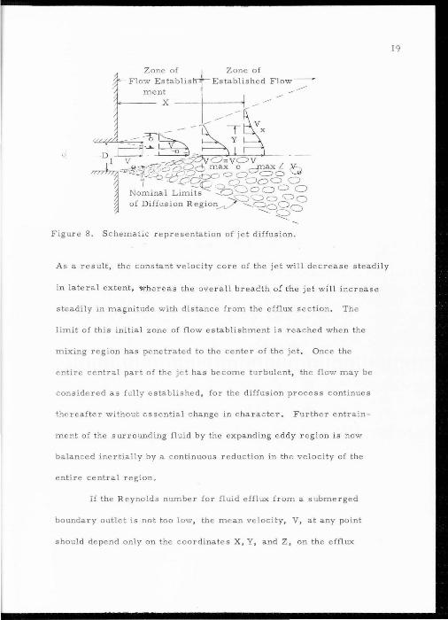
eferring to F igure 8, it can be seen that an initial zone of flow
establishment must exist beyond the efflux section of the three
ciimensional submerged jet . Since the fluid d ischarged from the
boundary opening may be assum d to have a relatively cons tant v loci ty,
ther necessarily will be a pronounc d velocity discontinuity b etween
the j t and the surrounding fluid. The eddies generated in this r egion
of high shPar w ill immediate ly result in a lateral mixing proces s
which progresses both inward and outward some dis tance from the
efflux section. Such lateral mixing produces a necessarily balanced
3.ction and reaction. The fl uid within the jet gradually is decelerated
and h e flu id irom the surrounding region gradually is a c celerated,
Zone of Flow E stablis
ment X
Zone of Established Flow-~
----
" /-: -I~ D - ~~ ---
11 ;~'SS25'd§3o £~Vf>d;:ax L 0 -.:z~ r->J:- -c;:; ClO o o =o
~-De;?~ .2) a CJo o o Nominal Limits ---..ag~ 0 ~ 0 of Diffusion R egion__,_/ --..__~gg~
~~
Figure 8. S chematic repr esentation of jet diffusion.
As a result, the constant velocity core of the jet will decrease steadily
in lateral extent, whereas the overall breadth o( the jet will increase
steadily m magnitude with distance from the efflux section. The
limit of this initial zone of flow establishment is rea ched when the
mixing region has penetrated to the center of the jet. Once the
ntire central part of th je t has become turbulent, the flow may be
consid . r d as fully established , for the diffusion process continues
thereafter without essential change in c haracter. Further entrain-
m nt of the surrounding fluid by the expand ing e ddy r egion is now
balanc ed inertially by a continuous reduction in the v locity of the
entire central region.
If the R eynolda number for fluid efflux from a submerged
boundary outlet is not too low, the mE>an velocity, V, at any point
should d pend only on the coordinates X, Y, and Z, on the efflux
19
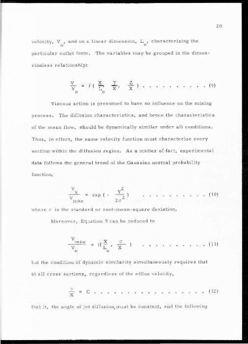
velocity , V , and on a linear dimension, L , characterizing the 0 0
particular outlet form. The variables may be grouped in the dimen-
sionless relationship:
v v
0
X f ( L"
0
y
x · z X ) • • ( 9)
Viscous action is presumed to have no influence on the mixing
process . The diffusion characteristics, and hence the c haracteristics
of the mean flow, s h ould be dynamic;<lly similar under all conditions.
Thus , in effect , the same velocity function must characterize ever y
section within the diffusion r eg ion. As a matter o f fact, experimental
data follows the general trend of the Gaussian normal probability
fun c tion,
v
20
X exp ( - • (10)
v max
wh re c; is the standard or root-mean-square deviation.
Moreover, E qua t i on 9 can be reduced to
v ~ v
Cl
X • ( 11 )
0
but the condition of dynamic similarity simultaneously requir es that
at all cross sections , regardless of the efflux velocity,
Cl
X c
that it , the angle of jet d iffusion, must b e constant, and the following
(12)
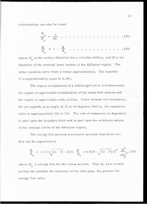
21
relationships can also be found
X 0
D 2C • ( 13)
0
D X D X
• ( 14)
0 0
where D is the orifice diameter. -for a circular orifice, and D is the 0
diameter of the nominal inner border of the diffusion region. The
latter equation came from a linear approximation. The quantity
Cis approximately equal to 0 . 081.
The region of expansion of a submerged jet is simultaneously
the region of appreciable modification of the mean flow pattern and
the re gion of appr c iable eddy motion. Under normal circumstances,
the jet e xpands at an angle of 12 to 14 degrees; that is, the e xpansion
r a tio is approximately 1:4 or 1:5 . The rate of expansion is depende nt
in part upon the boundary form and in part upon the arbitrary nature
of the nominal limits of the diffusion r e gion .
The e nergy flux pa s s ing suc c essive s e ctions beyond an ori -
fi c e can be xpressed as
~ E
0
1+2 (FD -2) c X D
0
x2 -2. (15)
(DJ
w h e re E0
i s energy flux for the e fflux se c t i on. That is, at a c ertain
s e ction the smaller the diame t e r of the inle t pipe, the gr e a te r the
nergy flux atio.
v
22
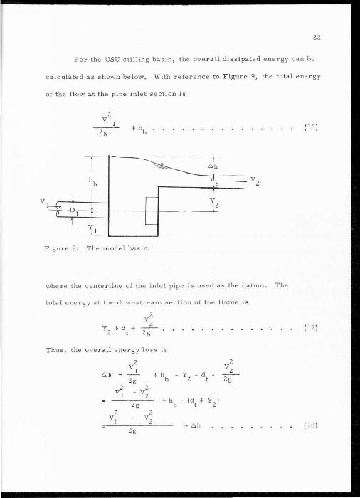
For the USU stilling basin, the overall dissipated energy can be
calculated as shown below, With reference to F igure 9, the total energy
of the flow at the pipe inlet section is
l
2 V I
2g
T y
-D I---1 · ~- -- - ---~ T -
( 16 )
Figure 9 . The model basin.
where t he cente r line of the inlet pipe is used as the datum. The
total ene rgy at the downstream se c tion of the flume is
(17)
Thus , the overall energy loss is
2 2
LI. E V I
+ hb d v2
= -- - y - -2g 2 t 2g
2 2 v l - v2
+ h (dt + Y2) = -2g b
2 2 VI - v2 - + Ll.h
2g (l fl )
23
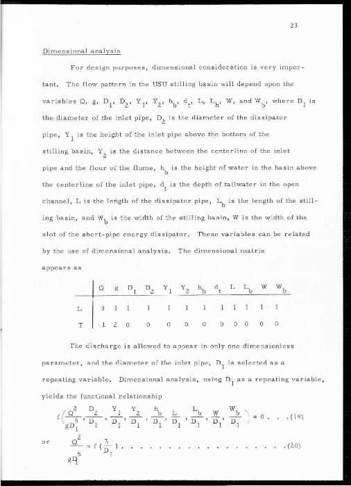
Dimensional analysis
For design purposes, dimensional consideration is very impor-
tant . The flow pattern in the US U stilling basin wi ll depend upon the
variables Q, g, D1
, D2
, Y I' Y2
, hb, dt, L, Lb, W, and Wb, where D1
is
the diameter of the inlet pipe, D2
is the diameter of the dissipator
pipe, Y 1
is the height of the inlet pipe above the bottom of the
stilling basin, Y2
is the distanc e between the centerline of the inlet
pipe and the floor of the fl ume , hb is the height of water in the basin above
the centerline of the inlet pipe, d t is the dep th of tailwater in the open
channel , Lis the length of the d issi pato:c p ipe , Lb is the l ength of the still-
ing basin, and Wb is the width of the stilling basin, W is the width of the
slot of the short-pipe energy dissipator. The se variables can be related
by the use of dimensional analysis. The dimensional matrix
appears as
w
L 3
T - ]_ 2 0 0 0 0 0 0 0 0 0 0
The d i scharge is allowed t o appear in only one dimensionles s
parameter, and the d iameter of the inlet pipe, D1
is s elected as a
repeating variabl e . D imensional analysis , using D1
as a r epeating variable ,
yields the functional relationship
f ( Q25 ' :2 ' :I ' :2 \ L Lb w wb \
0 0 . ( 19) DL ' Dl •n 'D' Dl g D
1 I I I I I
2
" or lL f(-) 0 (20) 5 Dl
g q
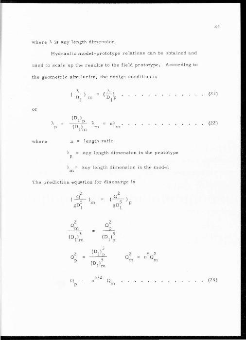
where A is any length dimension.
Hydraulic model-prototype relations can be obtained and
used to scale up the results t o the field prototype . According to
the geometric similarity, t he design cond ition is
or
where
A p
nA m
n = length ratio
A any length dimension in the prototype p
m any length dimension in the model
The p r ediction equation fo r discharge is
2 Q2 Q m _____e_
5 (D l)m
5 (Dl)p
5 2 ~ 2 5 2
Q Q n Q p 5 m m
(DI)m
Q 5/2
Q n p m
24
(21)
(22)
(23)
DESIGN OF DISSIPA TOR PIPE
The USU stilling basin has been developed as a transition for
pipe flow to open channel flow. The dimensions of the dissipater pipe
in relation to the stilling basin are of primary importance in dissipa
ting excessive energy in the basin. In the earlier studies by Rasheed
(1 963 ), the following dimensionless ratios were used: D2
/ D 1
l. 85; L/D1
1.0; and W/Dl = 0.5. In order to substanbate
Rashe ed's work, a comprehensive study regarding the design of the
dissipater pipe was undertaken.
Equipment
The first model cons isted of a 3 1/4 inch diameter pipe (D 1)
connected to a box-like stilling basin, 18 inches wide and 10 inches
long. The stilling basin was connected to a rectangular flume having
the same width as the stilling basin . A tail ga te was located at the
downstream end of the flume to control the tailwater depths in order
to eva luate the effect of varying the tai lwater depth.
An elbow meter, which consisted of a 90-degree flang ed
elbow and a manometer, wa s located upstream from the in l et pipe
in order to measure the flow rate, or discharge. A short-pipe energy
dissipater was placed on the wall of the basin opposite the incoming
submerged jet. The location of the dissipater pipe in the stilling
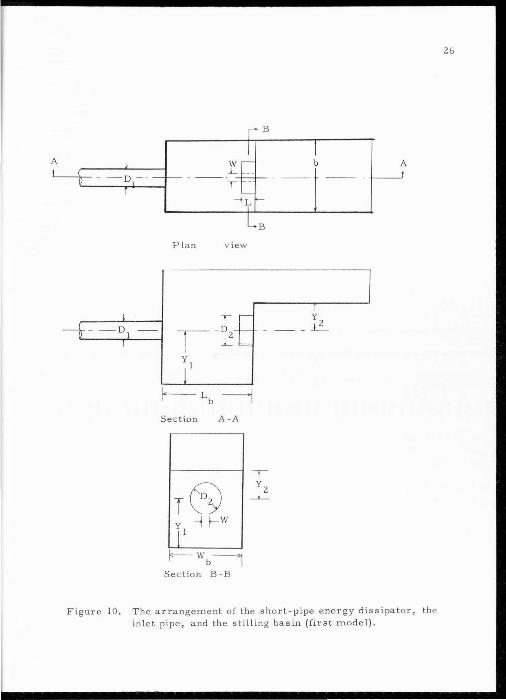
basin is shown in Figure 10.
25
A I
--~ -- -- ---~-t:- . L
Plan v iew
r
Sec tion A -A
f-- w b------, Section B - B
I b
T y
_L
I
A _____j
Figure 10 . The arrangement of the short-pipe energy dissipator, th e inlet pipe, and the stilling basin (first model) .
26
A Sonic Surfa ce -wave transducer connec ted to a Texas X- Y
recorder was used to record the fluctuations and the profiles of the
water surfaces in the stilling basin and the flume . The Sonic Surface
wave Transducer is a device to assist in recording the profile of
surface waves. It operates by measuring the time of propagation
27
of a sonic pulse from a transmitter to the changing surface and return,
timing the duration of travel of the sonic pulse, and converting these
time samples into a stepped voltage output which will closely approxi
mate the form of the surface profile.
Experiments
In the design of the short-pipe energy dissipater, the vari
ables involved are the diameter of the dissipater pipe, D2
, the length
of the dissipater pipe, L, and the slit width, W. In order to see how
each variable effects the overall performance of the stilling basin,
one of the three dimensions was varied while the other two remained
fixed . At the same time, the geometry of the stilling basin was fixed.
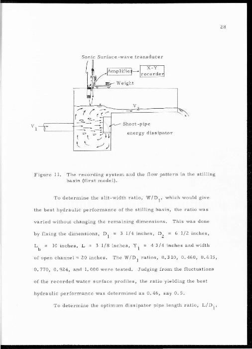
An extensive study was then made with the aid of the S onic
Surface -wave transducer, which was connected to a Texas X - Y re
corder (Figure II). The effectiveness of various sizes and locations
of the short pipe energy dissipater was observed and measured by
utilizing the unsteadiness of the water surface in the stilling basin
as a criterion.
Sonic Surface -wave transduc er
Figure II. T he recording system and the fl ow pattern in the stilling basin (first model).
T o determine the slit-width ratio, W/D1
, which would give
the best hydraulic performance of the stilling basin, the ratio was
varied without changing the remaining dimensions. This was done
b y fixing t he dimensions, D1
= 3 1/4 inches, D2
= 6 1/2 inches ,
Lb = 10 inches, L = 3 1/8 inches , Y 1
= 4 3/4 inches and width
of open c hannel= 20 inches. The W/D1
ratios, 0.310, 0.460, 0.615,
0 . 770, 0. 924, and I. 000 were tested. Judging from the fluctuations
of the recorded wate r surface profiles, the ratio yielding the best
hydraulic performance was determined as 0 . 46, say 0. 5.
To determine the optimum diss ipator pipe length ratio, L/ D ·1
,
28

the ratios 0. 90, I. 10, I. 15, and I. 39 were tested . The dimensions
o1
= 3 1/4 inches, D2
= 6 1/2 inches, W = I 1/2 inches, andY 1
29
= 4 3/4 inches were fixed. Thus, l ength s of dissipater pipe of 3. 825,
4. 675, and 4. 888 inches were used. The best results , using the
roughness of the water surface as the criteria , was obtained at ratios
in the vicinity of I. 0 . Consequently, for practical design purposes,
a value of I. 0 can be used for the ratio L/D 1
.
To determine the optimum diameter ratio, D2
/ D1
, values of
1.45 , I. 69 , and I. 77 were tested . The dimensions, L = 3 1/8
inches, W = I 1/2 inches andY 1
= 4 3/4 inches were fixed . The
highest ratio of L/D1
used in the tests, I . 77, appear ed to give the
b~st results. According to Rous ~ (1950), und~r normal circumstances
the expansion ratio of the region of expansion of a submer ged jet is
approximately 1:4 or 1:5. Since the length of the stilling box is 10
inches, the diameter of the expanding jet wi ll be approximately 6
inches when it reaches the short-pipe energy dissipater. Accordingly,
a dissipater pipe w ith a diameter of 6 inches will cover the whole
portion of the jet. Consequently, a diameter ratio of 2. 0 is suggested .
DESIGN OF STILLING BAS IN
Model basin
Using t he demens ionless ratios obtained from the previous
study regarding the dissipater pipe, the second phase of this research
effort , which is concerned with optimizing the design of the stilling
basin structure , was undertaken . To facilitate this phase of the
study, a steel box was fabricated having a height of 6 feet , a length
of 4 feet, and a width of 4 feet. Steel guides we re we ld ed on the
inside of the steel box to form vertical and horizontal rows of guides
to facilitate changing the dimensions of the stilling basin. A wooden
flume, 22 inche s wide, 6 feet long, and 20 inches high served as the
outflow channe l fo r the stilling basin structure . F igure 12 shows the
dimensions of the stilling basin. In Figure 13 the entire structure
is shown, while Figur e 14 shows the inside view of the stilling basin .
The height of the floor of the flume and the width of the stilling
basin could be adjusted . The length of the basin could be a d justed
from 6 . 5 inches to 24 inches, the width of the basin could be adjus ted
from 14 inches to 48 inches, and the height of the flume could be
adjusted from 9. 75 inches to 37 inches . Three inlet pipes with inside
diameters of 3 1/4 inches, 6 inches , and 10 inch s were used in the
study. To measure the flow rate, a 12-inch Parshall flume was in
stalled and cal ibrated.
30
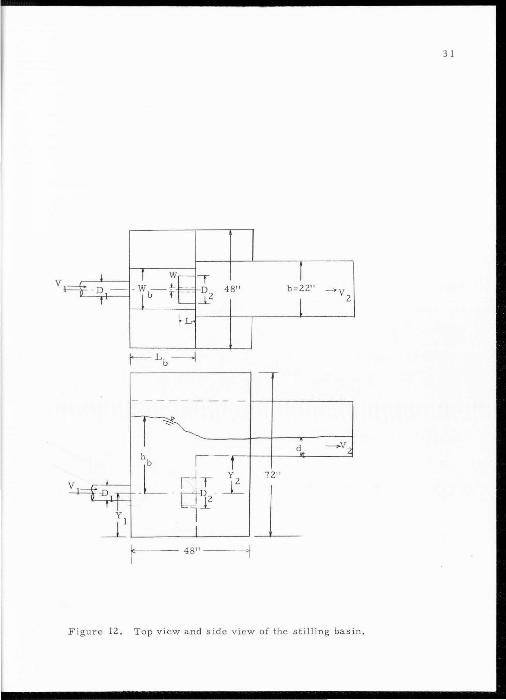
3 1
v I - ~-;E I I
- D - D2 48" b=2211
-+y 2 T' I b T - _i' l
~L-
j"-- Lb ------j - ,
-- ------ -
r =
d - v2
hb 1 - J .l_ L I~T Y2
7211 v
-D ,-r- - - o~ · _L l_ I L y 1 l
_L I
I· 48"-- -1
Figur e 12. Top view and sid e view of the stilling basin.
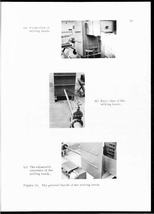
{a ) F ro nt \' i ew o f s t i ll i ng ba sin.
(c) The adjustable s tructure of the stilling basin .
(b) Rear view of lhe stilling ba sin.
Figure 13. The general layout o f th e stilling basin .
32
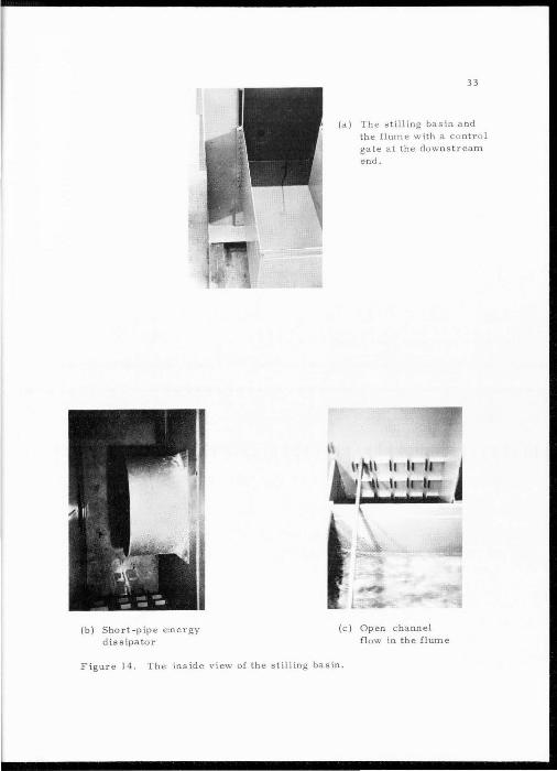
(b) Short-pipe energy dissipater
33
(a) The stilling basin and th e flume with a control gate at the downstream
end.
(c) Open channel flow in the flume
Figure 14. The inside view of the stilling basin.
Experimental design
The initial tests were conducted using a 3 1/4 inch inlet
pipe connected to the stilling basin. A r ange of dis charges between
1. 33 cfs and 0. 48 cfs was determined by taking into account the
maximum discharge available for the largest inlet pipe used ( 10
inches) and the minimum value at which an energy dissipation struc
ture might be desirable. An intermediate discharge of 0. 80 cfs
was also used in this study. The proper discharge to be used for
other inlet pipe sizes can be obtained from Equation 23 .
According to some preliminary observations, as the flow
entered the stilling basin from the inlet pipe, the jet impinged upon
the short-pipe energy dissipater, was turned upon itself and then
rose to the surface in turbulent "bo ils," which caused surging of
the water surface in the stilling basin. In the case of rough turbulent
boils, the Sonic Surfa ce-wav e transducer could not be used. Under
these conditions, the surging or the boiling action of the water sur
face in the sti ll ing basin was visually observed and the fluctuation
of the water surface was recorde d .
Each test was conduc ted using D2
/D1
= 2. 0, L/ D1
= 1. 0,
W/D1
0 . 5, andY /D1
= 1. 5. The remaining dimensionless
34
ratios, Wb/D1
, Lb/D1
, and Y2
/D1
were systematically varied through
out the testing program. In addition to varying W b' Lb, and Y 2
, the
inlet diameter, D1
, was also varied in order to evaluate scale effects.
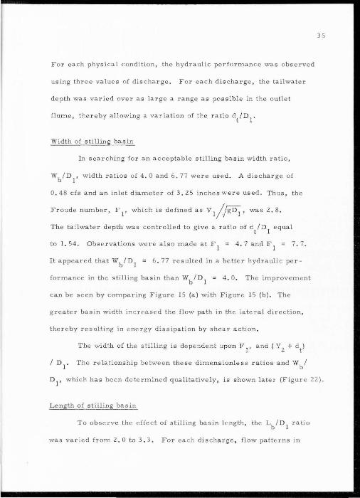
For each physical condition, the hydraulic pe rfo rmance was observed
using three v al ue s of discharge. For each discha rge, the tailwater
depth was varied over as large a range as possible in the outl e t
flume, thereby a llowing a variati on of the ratio d/D1
.
Width of stilling basin
In searching for an acceptable sti ll ing basin width ratio,
Wb/D1
, wid t h ratios of 4 . 0 and 6 . 77 were used . A discharge of
0 . 48 cfs and an inlet diameter of 3 . 25 inches w ere used. Thus, the
Froude numbe r, F I' which is defined as V I/fiD;., was 2 . 8 .
The tailwate r depth was controlle d to give a ratio of d/ D 1
equal
to I. 54. Observa tions were also made at F I = 4 . 7 and F I = 7. 7.
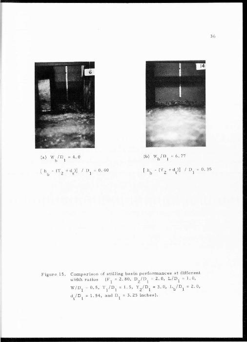
It appeared that Wb/ DI = 6. 77 resulted in a better hydraulic per
formance in the ·still ing basin than Wb/DI = 4. 0 . The improvement
can be seen by comparing Figure IS (a) with F igure I S (b). The
greater basin width inc reased the flow path in the lateral dir ection,
thereby resulting in energy dissipation b y shear action.
The width of the stilling i s dep ndent upon F I , a nd ( Y 2
+ dt)
I D1
. The relationship between the se dimensionless ratios and Wb/
35
D1
, which has been determined qualitative l y , is shown later (Figure 2 2 ) .
L ength of stilling basin
To observe the effect of stilling basin l ength, the Lb/ D1
ratio
was varie d from 2. 0 to 3 . 3 . For ea c h discha rge , flow patterns in
36
Figur e 15. Compariso n o f stilling basin performances at different width rat ios (F I = 2. 80, D/DI = 2. 0 , L / D 1 = I. 0,
W / D1
0 . 5, Y I / D1
= I. 5, Y z'Dl = 3. 0, Lb / D 1 = 2. 0,
d/D1
I. 54, and D1
= 3 . 25 inches).
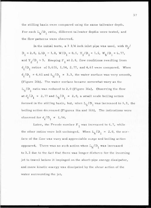
the stilling basin were compared using the same tailwa ter depth .
For each Lb i D1
ratio, differ e nt tailwater de pths were tested, and
the flow patterns were obs erved.
In the ini tial tests, a 3 I I 4 inch inlet pipe was us e d, with D2
I
D1
= 2.0 , LID1
= 1.0, WID1
= 0 . 5 , Y/DI = 1.5, WbiD1
= 6 . 77,
and Y2
1D1
= 3. Keeping F 1
at 2. 8 , flow conditions resulting from
d/D1
ratios of 0 . 6 15, l. 54, 2. 77, and 4 . 6 I were compared . When
d/ D1
= 4 . 6 1 and LbiD1
= 3 . 3, the wate r surface was ve ry smooth ,
(Figure 16b ) . The wat e r surface became somewhat wavy as the
~ID 1 ratio was reduced to 2. 0 (Figure 16a ). Observing the flo w
37
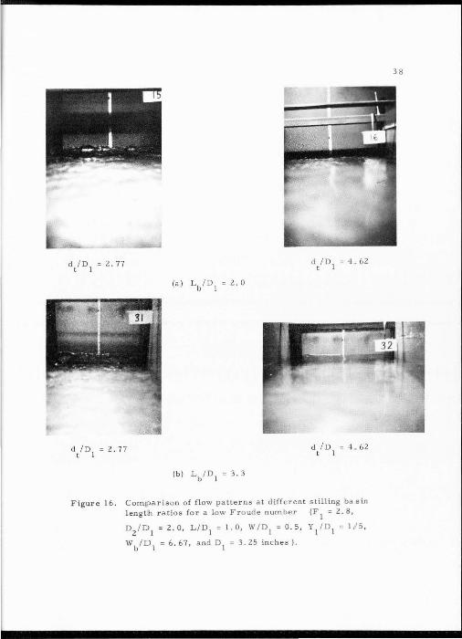
at d/D1
= 2. 77 and LbiD1
= 2. 0, a small scal e boiling action
formed in the stilling ba sin , but, when LbiD1
was inc reas e d to 3 .3, the
boiling action dec. rease d (Figures 16a and 16b) . The indica tions were
observed for d/D1
= I . 54 .
Later, the Froude number F 1
wa s increased to 4. 7 , while
the other ratios wer<> l eft unch anged . When LbiD1
= 2 . 0, the sur
face of the flow was wavy and appr ciable s u rge and boiling action
a ppe are d . There was no suc h a c t ion when LbiD1
was increasP d
to 3. 3 due to the fa ct that ther was longer distance for the incoming
je t to trave l before it impinged on the short-pipe energy dissi pator,
and more kinetic energy was dissipated by the shear a c tion of the
water s urrounding the jet .
diD 2.77 t I
dID 2.77 t I
diD =4 .. 62 t 1
Figure 16. Comparison of flow patterns at different stilling basin lengt:h ratios for a low Froude number (F
1 = 2. 8,
D2
1D1
= 2.0, L ID1
= 1.0, WID1
= 0 . 5, Y1
1D1
c 1 ,1 5,
WbiD1
= 6 . 67, and D1
= 3. 25 inches) .
38
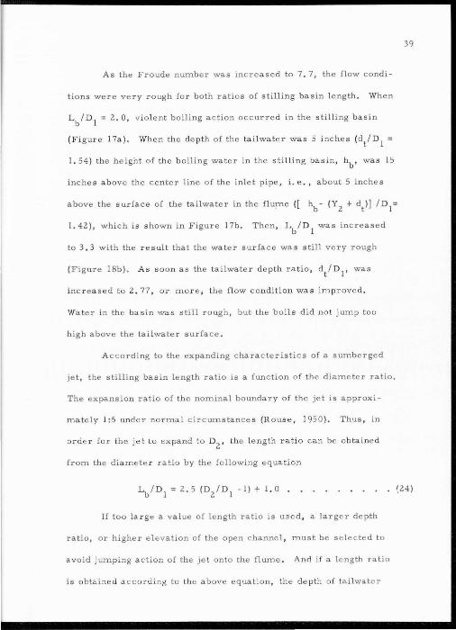
As the Froude number was increased to 7. 7, the flow condi-
tions were ve ry rough for both ratios of stilling basin length. When
Lb/D1
= 2. 0, vio lent boiling action occurred in the stilling basin
(Figur e 17a) . When the depth of the tailwate r was 5 inches (d/D1
=
I. 54) the height of the boiling water in the stilling bas in , hb , was 15
inches above the center line of the inlet pipe, i.e. , about 5 inche s
above the surface of the tailwater in the flume ([ ~- (Y2
+ dt )] / D1=
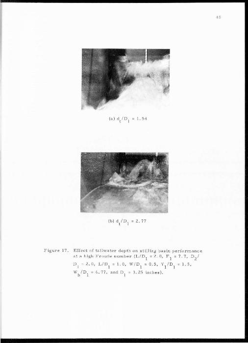
I . 42), which is s hown in Figure 17b. Then, Lb / D 1
was increased
to 3 . 3 with the result that the water surface was still very rough
(Figure 18b). As soon as the tailwater depth ratio, d/D1
, was
increased to 2. 77, or more, the flo w condit ion was improved .
Water in the basin was still rough, but the boils did not jump too
high above the tailwater surface.
According to the expanding characte ristics of a sumberged
jet, the stilling bas in length ratio is a function of the diameter ratio.
The expansion ratio of the nominal boundary of the jet is approxi
mately 1:5 under normal circumstance s (R ouse , 1950) . Thus , in
or der for the je t to expand t o D2
, the l ength r a tio can be obtained
from the diameter ratio by the following equation
39
. {24)
If too la r ge a value of length ratio is used , a large r depth
ratio, or higher elevation of the open c hannel , must be sele cted t o
avoid jumping action of the jet onto the flume. And if a l e ngth ratio
is obtained accor d ing to th e above equation , the d e p th of tailwate r
F igur e 17. Effect of tailwater dep th o n s t illir.g basin p erfo rma nce a ta high F r oudenumber (L/0
1 ~2.0, F
1 ~7.7 , Ozl
01
~ 2.0, L / 01
~ 1.0, W/01
~ 0.5, Y/01
~ 1. 5 ,
Wb / 01
~ 6.77 , a nd 01
~ 3 . 25 inches).
40
Figure 18. Comparison of stilling basin performances at different length ratios for a high Froude number (F
1 = 7. 7, D
21
D1
= 2.0, LID1
= 1.0, WID1
= 0 . 5 , Y1
1D1
= 1.5, Wbl
D1
= 6 . 77, d/Dt = I. 54, and D1
= 3. 25 inches).
41
42
requir e d to achieve a certain d egree of energy dissipation is pri
marily a functio n of the FToude number, F 1
. Since the diameter ratio
has already been selected as 2. 0 , the still ing basin length ratio
b ecome s 3. 5.
Tailwater elevation
The tailwater elevation, which has a pronounced effect on
ene rgy dissipation in the stilling basin , is a combination of the floor
elevation of the outlet flume, Y 2
, plus the depth of flow in the outlet
flume, dt , which is often referred to as tailwater depth. To test
the effect of the flume floor e levation, a 6-in ch inlet pipe was installed
and the fo llowing d imensionless rat ios were used in initial tests:
D2
/ D1
= 2.0, L/D1
= 1. 0 , W / D1
= 0 . 5, Y/ Dl = l.5 ,Wb/ D1
= 4.0
and Lb/D1
= 2. 0 . The Y2
/ D1
ratio was varie d from I. 50 to 3. 00 ,
while F 1
= 3. 5 (Q = 2. 73 cfs) was maintained for the initial tests.
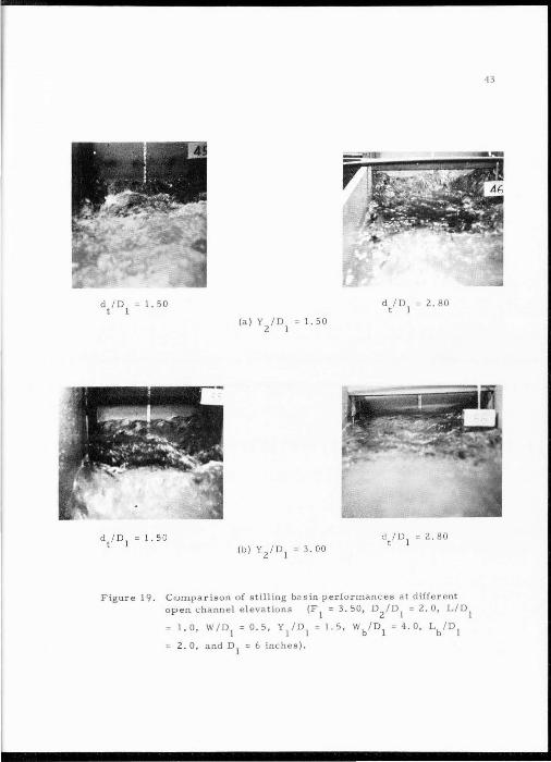
By increasing the relative height of the wall oppos ite to the incoming
jet in th stilling basin, it was found that the differ nc between
elevations of the water surface in the basin and the tailwater surface
in the flume c ould be reduc d, as would be expe c ted, and a more
uniform flow in the flump c oul d be obtained. The difference can be
seen by compa.ring the flow patterns for different values of Y2
/D1
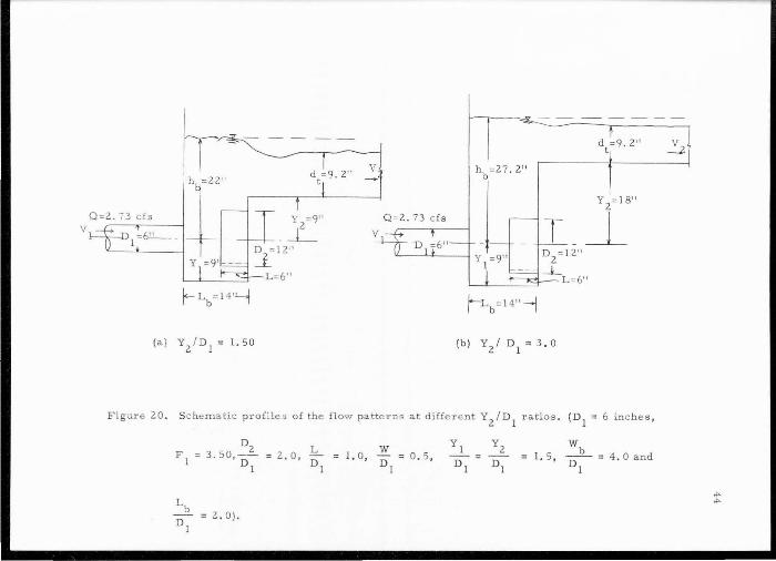
as shown in Figure 19. The s c hematic profiles for bo t h case s of
Y2/n
1 are shown in Figure 20. Then , keeping Y
2/D
1 = l. 50 and using
the 3. 25-inch inlet pip , the Froud number was increa s e d to 4 . 70.
d /D t I
I. 50 d I D = 2. 80 t I
Figure 19. C comparison o f stilling bas in performances at different o pen c hannel e l evat ions (F
1 = 3. 50, D
2/D
1 = 2. 0, L/D
1
1.0, W/DI = 0 . 5 , Y/D l = 1.5, Wb/D 1 = 4.0 , Lb/D 1
2 . 0, and D1
= 6 inches) .
43
v
Y 2
=18"
Q=2. 73 cfs _L
(b) Y/ D1
= 3.0
F igur 20, Schematic proHl of the flow patterns at different Y2
/ D1
ra tios . (D1
= 6 inches ,
w r. o, 0 = o.5, 1
wb I. 5, -- = 4 . 0 and
Dl
l . 54
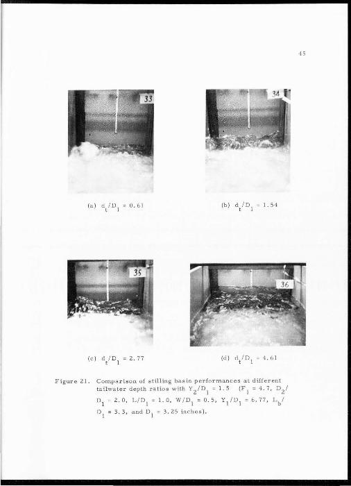
Figure 2 1. Compar ison of stilling basin performances at different tailwater depth ratios withY
2/D
1 = l . 5 (F
1 = 4. 7, D/
D1
= 2.0, L/D1
= 1 . 0, W / D1
= 0.5, Y/Dl = 6.77, Lb /
D1
= 3 . 3 , and D1
= 3. 25 inches) .
45
Flow cond itions or flo w patte rns at different tailw ater depths wer e
observed . The effec t of varying the tailwate r depth is dramatic ally
shown in Figure 21.
T o eval uate the relation b etwee n the tailwate r depth ratio,
d/D1
, and the outlet fl ume floor e l e vation ratio, Y2
/D1
, the he ights
o f the boils in the basin we r e r ecor de d , and denoted by hb . It was
found that the elevation diffe r ence between the top of the b oil and the
surface of the open channe l flo w is a function oqY2+ dt) /D
1. The
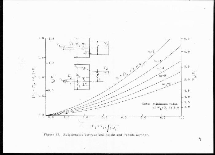
r e lationship is shown in Figur e 22 wi th [ hb - (Y 2
+ dt)] I D 1
versus
F 1
a t different va l ues of m = (Y2
+ dt)/D1
•
In a practical s i tuati on, the tailwater elevation will b e di c
tate d by downstream c onditions . F or any s e l ec tion of Y2
, the height
of the boil can be predicted from F igur e 22 . When the inl e t pipe
d iamete r, the d i s cha rge , and the tailwa t e r de pth are known, the
height of the boil can be minimized by increasing Y 2
• F o r d esign
purposes, the required fre eboard in the stilling basin n eeds to b
s pecifie d . The amount of freeboard has b een rela ted in a q ualitative
manner , to the bo il h e ight of th water in the sti lling basin, a nd is
shown in F igur e 22.
Design example
The following sample probl m illustrates the use of the d esign
criteria presented in this thesis.
Maximum dis charge, Q, is 100 cf s .
46
1.5 6.3
6.0
0 . 0 0.0
Fl =Vl/ F> Figure 22, R elationship between boil height and Froude numbe r.
48
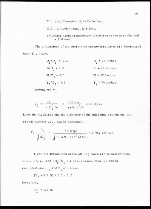
Inlet pipe diameter, D1
is 24 inches.
Width of open channe l is 6 feet .
Tailwater depth at maximum discharge in the open channel is 3. 0 feet .
The dimensions of the short-pipe ene rgy dissipator ar e de t ermined
fr om D1
, a l one,
D/ Dl = 2.0
L / D1
= I. 0
W / D1
= 0 . 5
Y/ DI = 1. 5
Solving for V 1
_Q __ 2
TT Dl /4
D2
= 4 8 inches
L = 24 inches
W = 12 inches
Y 1
= 36 inches
100 cfs
TT (2ft. )2
/4 3 I. 8 fps
Since the discharge and the diame ter of the inle t pipe are known, the
Froude number , F 1
, c an be compute d.
J 32.2 ft. /sec2
(2ft.)
3 1 .8fps 3. 96 , s ay 4. 0
Now, the dimensions of the stilling basin can b e determined.
If m = 3 (i.e. ( 1 / 2 + '\)/D1
= 3. 0) is cho sen, then 1 /2 can be
computed since dt and D1
ar e known .
( Y 2
+ 3. o ft) I 2 ft = 3. o
therefore,
y 2 3. 0 ft.
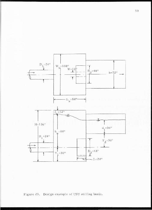
To determine the boil height in the stilling basin enter Figure
22 with F 1
= 4. 0 and m = 3. 0, which g ives
[hb- (Y2
+ dt)] I D1
= 0.65 i.e. hb = 87.6 inches, say
88 inches. Als o for F 1
= 4. 0 and m = 3. 0, the freeboard ratio,
fb/D1
, is obtained fr om F igure 22 .
fb / D1
= 0. 5 i.e. fb = 12 inches
The height of the stilling basin box, H, will be
H = Y 1
+ hb + fb = 136 in. + 88 in. + 12 in. = 136 inches
The length of the stilling basin is dependent upon D1
.
Lb / D1
= 2.5 (D2
/D1
- J) + 1.0 = 3.5
i.e. Lb = 84 inches
Entering Figure 22, again , with F 1
= 4 . 0 and m = 3. 0, the stilling
basin w idth ratio, Wb/D1
, is 4.5. Therefo re
wb = 4.5 (24 inches)= 108 inches
A drawing of thi s design is shown in Figure 23.
In conclus ion , it should be pointed out that the choice of m
in this example was arbitrary . In an ac tual f i e ld situation the value
of m may be fixed by existing physical cond itions . If this is not the
case, then preliminary designs should be computed for a number of m
values and the most economical design would be chosen.
49
50
w = 10811
b W:l_2' b=7 2"
T
H=l3 6" d =36"
Y 2
=36"
- _L
Figur e 23, Design example of USU stilling basin .
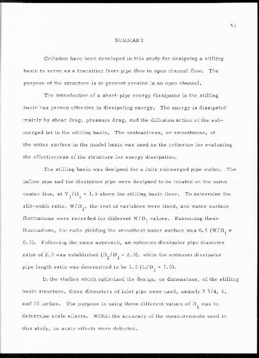
SUMMARY
Criterion have been developed in this study for designing a stilling
basin to serve as a transition from pipe flow to open channel flow. The
purpose of the structure is to prevent erosion in an open channel.
The introduction of a short-pipe energy dissipater in the stilling
basin has proven effective in dissipating energy. The energy is dissipated
mainly by shear drag, pressure drag, and the diffusion action of the sub
merge d jet in the stilling basin. The unsteadiness, or smoothness, of
51
the water surface in the model basin was used as the criterion for evaluating
the effectiveness of the structure for energy dissipation,
The stilling bas in was designed for a fully submerged pipe outlet. The
inflow pipe and the dissipater pipe were designed to be located on the same
center line, at Y/D1
= 1.5 above the stilling basin floor. To determine the
slit-width ratio, W/D1
, the rest of variables were fixed, and water surface
fluctuations were recorded for different W/D1
values, Examining these
fluctuations, the ratio yielding the smoothest water surface was 0. 5 (W/D1
0, 5 ). Following the same approach, an optimum dis sipator pipe diame ter
ratio of 2, 0 was es tablished (D2
/ D1
= 2, 0), while the optimum dissipater
pipe length ratio was determined to be I. 0 (L/D1
= I. 0).
In the studies which optimized the design, or dimens ions, of the stilling
basin structure, three diameters of inlet pipe were used, namely 3 1/4, 6,
and 10 inches. The purpos e in using three d i fferent values of D1
was to
determine scale effects. Within the accuracy of the measurements used in
this study, no s c ale effects were detected • .
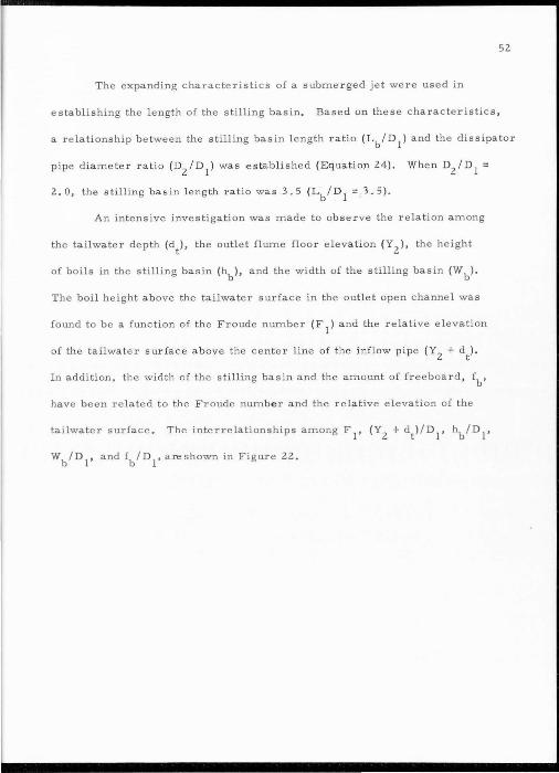
52
The expanding characteristics of a submerged jet were used in
establishing the length of the stilling basin. Based on these characteristics ,
a relationship between the stilling basin length ratio (Lb/D1
) and the dissipater
pipe diameter ratio {D2
/D1
) was es tablished (Equation 24). When DzlD 1 =
2.0, the stilling basin l ength ratio was 3.5 {Lb/ D1
= 3.5) .
An intensive investigation was made to observe the relation among
the tailwater depth (d t )' the outlet flume floor elevation ( Y2
), the height
of boils in the stilling basin (~ ), and the width of the stilling basin {Wb) .
The boil height above the tailwater surface in the outlet open channel was
found to be a function of the Froude number (F 1
) and the relative elevation
of the tailwater s urfac e above the center line of the inflow pipe {Y2
+ dt) .
In addi ti on. the width of the stilling basin and the amount of freeboard , fb,
have been related to the Froude numbe r and the relat ive elevation of the
tailwater surface . The interrelationships among F 1
, (Y2
+ dt ) /D1
, hb/D1
,
Wb/D1
, and fb/D1
, are shown in Figure 22 .

LITERATURE CITED
Albertson, M. L., X . B. Dai, and Hunter R ouse. 1950. Diffusion of subme rged jets . ASCE T ransac tions, pp. 665-693 .
Beichill , G. L. 1956. Hydraulic mode l study on outlet wo r ks at
53
Carter Lake R eservoir. USB ureau of Reclamation, Laboratory R eport. Hyd . 3 94.
Bradley, J.N . and A . J. Peterka . 1957. Small bas ins for pipes or open channels. Journal of the Hydraulic Division, ASCE, Vol. 83, No . HY5, P roc . Paper 1406 , October .
Chow, VenTe. 1959 . Open channe l hydraulics . McGraw-Hill Book Company. New Yor l<. 680 p.
Davis , C . V . 195 2. Handbook of Applied Hydraulics. McGraw-Hill Book Company. New Yo r k . 1272 p .
Elevatorski, E . A. 1959. Hydraulic energy dissipaters . McGraw-Hill Book Company. New York. 214 p.
Fiala, Gene R. 196 1. Manifold stilling basin . Journal of the Hydraulic Division, ASCE, Vol 87, No. HY4 , Proc . P aper 2863. July.
Gibson, A.H. 1952. Hydraulics and its applications . Constable & Company LTD, London . 486 p .
Gnelton, Weingaertner, and Sevin . 1953 . Lo ck controlled operation of the industrial diversion works on the lower Durarce . A SCE Transactions, pp. 5 97-6 12 .
Ke im, S.R. 1962 . Contra Costa ene rgy dissipater . Journal of the Hydraulic Division, ASCE , Vol . 88, Proc. Paper 3 077 . March .
Leliavsky, Serge . 1960 . Irrigation and hydraulic design. Chapman and Hall, L td. London. Vol. I. 492 p .
Peterka , A. J. 1957. Impact type energy dissipater for flow at pipe / outlets . U.S. Bureau of R eclamation, Laboratory R eport . Hyd.
398. June .

54
LITERATURE CITED (C ontinued)
Ra sheed, Hameed. 1963 . Utah State University stilling bas in, pipe flow to open channels. Unpublishe d M.S. Thesis . Utah State University Library, L ogan, Utah.
Rouse, H. 1950. E ngineering hydraulics . John Wiley & Sons, Inc . New York. 1039 p .
Smith, Gordon G. and Bobby Earl Price. 1963. L aboratory manual for fluid mechanics . School of Civil E ngineering, T echnical Publication No . 6, Oklahoma State University , S tillwater, Oklahoma.
Tabor, H . W., and A. T. Peterka. 1950 . Progress in new designs for outle t works stilling basin, U.S. Bureau of R eclamation , Hydraulic Laboratory R eport 302 .
Unite d States Bureau of R eclamation. 1958 . basin and bucket energy dissipators . No. 25 . September .
Hydraulic d e sign of stilling E ngineering Monograph
United States Bureau of Reclamation. 1946. H ydraulic model studies of Deer Creek dam spillway and outlet works and a report on the operation of the prototype tybe values and stilling basin , Hydraulic Lab . R ep . 215 , November .

VITA
Chi-Yuan Wei
Candidate for the Degree of
Master of Science
Thesis: Design Criteria for USU Stilling Basin Pipe Flow to Open Channels
Major Field : Civil Engineering
Biographical Information:
Personal Data: Born at Tokyo, Japan, December 17, 1940, son of Dr. and Mrs. Ping-Yen Wei.
55
Education: Attended elementary school in Taipei, Taiwan; graduated from the High School of Taiwan Teachers College in 1959 ; received the Bachelor of Science degree from Taiwan Christian College of Science and Technology, with a major in Hydraulic Engineering, in 1963.
Pr ofessional Experienc e : 196 5 to present, student research assistant at Utah Water Research Laboratory; 1964-65, worked in Taiwan Power Company (hydrologic study); 1963-64, served in Chinese Army as Company Administrator (ROTC).