design criteria for infrastructure for coastal line
TRANSCRIPT

Consultancy Service for the Feasibility Study and Detailed Design of Colombo Suburban Railway Project
Design Criteria for Infrastructure
for Coastal Line
DOHWA Engineering Co. Ltd in JV with
Oriental Consultants Global,
BARSYL in association with
PCKK, RDC, CEA and CESL
September 30, 2020
Design Criteria for Infrastructure

- i -
Chapter 1 Introduction ............................................................................................................... 1
1.1 General ................................................................................................................................ 1 1.2 Background and Objective .................................................................................................. 1
1.2.1 Background ...................................................................................................... 1
1.2.2 Objective .......................................................................................................... 1
1.3 Scope of Work ..................................................................................................................... 2
Chapter 2 Hydraulic Structures ................................................................................................. 1
2.1 Hydrological Parameters ..................................................................................................... 1 2.1.1 Rainfall Intensity Duration Frequency Curve information of the rainfall
stations which has an influence on the proposed railway trace ....................... 1
2.1.1.1 General........................................................................................................... 1
2.1.1.2 The status of these IDF curves ....................................................................... 1
2.1.1.1 IDF Curves .................................................................................................... 1
2.1.2 Theissen Polygons to Determine the Area of Influence of IDF Curves ........... 3
2.1.3 Selected Recurrence Interval (Return Period) ................................................. 4
2.1.3.1 General........................................................................................................... 4
2.1.4 Considered scenarios ....................................................................................... 4
2.1.5 Design Rain Events Used to Generate Catchment Flow for Different Return
Periods ............................................................................................................. 4
2.1.6 Runoff Coefficients for Rational Method ........................................................ 5
2.2 Hydrologic and Hydraulic Design of Minor Cross Drainage Structures (for Minor Catchments) ......................................................................................................................... 5
2.2.1 General ............................................................................................................. 5
2.2.2 Catchment delineation ..................................................................................... 6
2.2.3 Selection of Runoff Coefficients...................................................................... 6
2.2.4 Computation of Time of concentration (Tc) for Bridges and Cross Culverts
for Rational formula......................................................................................... 6
2.2.5 Recurrence Interval (Return Period) ................................................................ 6
2.2.6 Computation of Peak flow ............................................................................... 7
2.2.7 Hydraulic Design of Cross Drainage Structures .............................................. 7
2.2.7.1 General........................................................................................................... 7
- ii -
2.2.8 Regular Factor of Safety of Hydraulic Structures ............................................ 8
2.2.8.1 Factor of Safety through Return Period ......................................................... 8
2.2.8.2 Factor of Safety through Free Board ............................................................. 8
2.2.8.3 Factor of Safety through the Updating the IDF Curve .................................. 8
2.2.8.4 Factor of Safety through the extra lengths of structure dimensions .............. 8
Chapter 3 Alignment Design ..................................................................................................... 1
3.1 Design Principles ................................................................................................................. 1 3.2 Specifications for Potential Speed on Curves ..................................................................... 1
3.2.1 Cant and Cant defficiency for broad gauge ..................................................... 1
3.2.1.1 Cant ................................................................................................................ 1
3.2.1.2 Cant deficiency .............................................................................................. 2
3.2.1.3 Cant and Cant deficiency ............................................................................... 3
3.2.1.4 Speed formula ................................................................................................ 3
3.2.1.5 Transition Curve ............................................................................................ 4
3.2.1.6 Length of Straight track between two horizontal curves ............................... 4
3.2.1.7 Vertical alignment: gradient ........................................................................... 5
3.2.1.8 Vertical curve ................................................................................................. 5
3.2.1.9 Comparison of Alignment Design Criteria .................................................... 6
3.2.1.10 Summary of Design Criteria ........................................................................ 8
Chapter 4 Stations ...................................................................................................................... 1
4.1 Architecture ......................................................................................................................... 1 4.1.1 General Provisions ........................................................................................... 1
4.1.1.1 Design Approach ........................................................................................... 1
4.1.2 Programming ................................................................................................... 2
4.1.2.1 Site and Traffic Plan ...................................................................................... 2
4.1.2.2 Block Planning .............................................................................................. 3
4.1.3 Square Planning ............................................................................................... 4
4.1.3.1 Cant ................................................................................................................ 4
4.1.4 Square Scale Plan............................................................................................. 4
- iii -
4.1.5 Pedestrian Movement Plan .............................................................................. 5
4.1.6 Transportation and Parking Plan ...................................................................... 5
4.1.7 Shape and Design............................................................................................. 6
4.1.7.1 General........................................................................................................... 6
4.1.8 Material ............................................................................................................ 8
4.1.8.1 General........................................................................................................... 8
4.1.8.2 Material Selection .......................................................................................... 8
4.1.9 Architecture Design ......................................................................................... 9
4.1.9.1 General Requirements for Buildings ............................................................. 9
4.1.10 Handicapped Facility .................................................................................... 11
4.1.10.1 General....................................................................................................... 11
4.1.11 Building Structures ........................................................................................ 11
4.1.11.1 Fundamental Approach .............................................................................. 11
4.1.11.2 Applicable Scope ....................................................................................... 12
4.1.11.3 Structural Design ....................................................................................... 12
4.1.12 Architecture Environment .............................................................................. 12
4.1.12.1 General....................................................................................................... 12
4.1.12.2 Thermal Environment ................................................................................ 12
4.1.12.3 Air Quality ................................................................................................. 13
4.1.12.4 Sunlight Environment ................................................................................ 13
4.1.12.5 Sound Environment ................................................................................... 13
4.1.13 Building Equipment Design ........................................................................... 13
4.1.13.1 General....................................................................................................... 13
4.1.13.2 Building Mechanical Facility Design ........................................................ 14
4.1.14 Fire and Evacuation Plan ............................................................................... 14
4.1.14.1 General....................................................................................................... 14
4.2 Station Building Electrical Design .................................................................................... 15 4.2.1 Design ............................................................................................................ 15
4.2.1.1 General......................................................................................................... 15
4.2.1.2 Applicable design standards and codes ........................................................ 15
4.2.2 Power Supply and Distribution System ......................................................... 15
4.2.3 Lighting .......................................................................................................... 16
- iv -
4.2.4 Lightning protection and earth system ........................................................... 16
4.2.5 Uninterruptible Power Supply (UPS) ............................................................ 16
4.3 Mechanical and Plumbing ................................................................................................. 17 4.3.1 Ventilation and Air Conditioning (VAC) system ........................................... 17
4.3.1.1 General......................................................................................................... 17
4.3.1.2 The design criteria for the VAC system ....................................................... 17
4.3.1.3 Split type and packaged direct expansion air conditioners air cooled ......... 18
4.3.1.4 Ventilation for Plant rooms .......................................................................... 19
4.3.1.5 Ventilation for toilets ................................................................................... 19
4.3.1.6 High Volume Low speed fans (HVLS) ........................................................ 19
4.3.2 Water Supply System ..................................................................................... 19
4.3.2.1 General......................................................................................................... 19
4.3.2.2 Design Criteria ............................................................................................. 19
4.3.3 Provision for Retail ........................................................................................ 20
4.3.4 Sanitary Plumbing system ............................................................................. 20
4.3.4.1 General......................................................................................................... 20
4.3.4.2 Plumbing system .......................................................................................... 20
4.3.4.3 Septic Tank System ...................................................................................... 21
4.3.4.4 Wastewater Treatment Plant ........................................................................ 21
4.3.4.5 Sanitary fixtures ........................................................................................... 21
4.3.4.6 Piping pit...................................................................................................... 21
4.3.5 Fire Detection & Protection System .............................................................. 21
4.3.5.1 Lifts .............................................................................................................. 21
4.3.5.2 Escalators ..................................................................................................... 21
Chapter 5 Civil / Infrastructure Structures ................................................................................ 1
5.1 Design Specification for Formation .................................................................................... 1 5.1.1 Summary .......................................................................................................... 1
5.1.2 Track bed works ............................................................................................... 1
5.1.2.1 Embankment Filling ...................................................................................... 1
5.1.2.2 Embankment (fill) Slopes and Slope Stability ............................................... 4
5.1.2.3 Cut Slopes and Slope Stability .................................................................... 15
- v -
5.2 Geotechnical Design .......................................................................................................... 21 5.2.1 References ...................................................................................................... 21
5.2.2 Estimation of Soil Parameters ........................................................................ 21
5.2.2.1 Estimation of corrected N value (N70) ........................................................ 21
5.2.2.2 Estimation of shear strength parameters of soil ........................................... 21
5.2.3 Estimation of Rock Mass Rating of rocks (RMR) ......................................... 22
5.2.3.1 Strength of Intact Rock ................................................................................ 22
5.2.3.2 Rock Quality Designation (RQD) ............................................................... 22
5.2.3.3 Spacing of Joints .......................................................................................... 22
5.2.3.4 Conditions of Joints ..................................................................................... 22
5.2.3.5 Groundwater ................................................................................................ 22
5.2.4 Estimation of carrying capacity of pile .......................................................... 23
5.2.4.1 Estimation of ultimate skin friction of bored piles ...................................... 23
5.2.4.2 Estimation of ultimate end resistance of bored piles ................................... 23
5.2.4.3 Allowable carrying capacity of piles ........................................................... 25
5.2.4.4 Negative skin friction .................................................................................. 26
5.2.4.5 Total load on piles ........................................................................................ 26
5.2.5 Estimation of Soil spring constants................................................................ 26
5.2.6 Estimation of Lateral load capacity of pile .................................................... 27
5.2.7 Estimation of deflection of vertical piles carrying lateral loads .................... 29
5.2.8 Estimation of settlement of single piles at the working load for piles socketed
in to the rocks ................................................................................................. 30
5.3 Bridges and Other Structures............................................................................................. 31 5.3.1 Introduction .................................................................................................... 31
5.3.1.1 Acronyms ..................................................................................................... 31
5.3.1.2 Definitions of structures .............................................................................. 31
5.3.2 Applicable norms and standards .................................................................... 32
5.3.3 Units and Sign convention ............................................................................. 33
5.3.4 Design Life .................................................................................................... 33
5.3.5 Materials ........................................................................................................ 34
5.3.5.1 Concrete ....................................................................................................... 34
5.3.5.2 Applicable Concrete and reinforced bars for each component .................... 34
- vi -
5.3.5.3 Durability ..................................................................................................... 35
5.3.5.4 Reinforcing steel .......................................................................................... 38
5.3.5.5 Prestressing steel .......................................................................................... 38
5.3.5.6 Structural steel ............................................................................................. 38
5.3.5.7 Partial factor for material ............................................................................. 39
5.3.6 Design principle ............................................................................................. 39
5.3.6.1 Design value of concrete strength and stress limit ...................................... 39
5.3.6.2 Design yield strength and stress limit of reinforcing steel ........................... 41
5.3.7 Design Loads ................................................................................................. 42
5.3.7.1 Dead Load.................................................................................................... 42
5.3.7.2 Prestressing .................................................................................................. 43
5.3.7.3 Creep and Shrinkage .................................................................................... 44
5.3.7.4 Earth Pressure .............................................................................................. 45
5.3.7.5 Loading due to Water Current, Floating debris and Log Impact ................. 45
5.3.7.6 Rail traffic actions........................................................................................ 46
5.3.7.7 Derailment actions from rail traffic on a railway bridge ............................. 51
5.3.7.8 Impact force of derailment train on the robust kerb .................................... 52
5.3.7.9 Live Load for Fatigue .................................................................................. 53
5.3.7.10 Live load pressure for Under bridge and culverts ...................................... 53
5.3.7.11 Actions for non-public footpaths ............................................................... 53
5.3.7.12 Temperature ............................................................................................... 54
5.3.7.13 Wind Load ................................................................................................. 57
5.3.7.14 Seismic Hazard .......................................................................................... 60
5.3.7.15 Differential Settlement ............................................................................... 61
5.3.7.16 Other actions due to track structure interaction ......................................... 61
5.3.7.17 Bearing Replacement ................................................................................. 63
5.3.7.18 Friction from Bearings ............................................................................... 63
5.3.7.19 Accidental actions ...................................................................................... 64
5.3.8 Load Combinations for railway bridges ........................................................ 65
5.3.8.1 Group of loads for rail traffic ....................................................................... 65
5.3.8.2 Ultimate limit state (ULS) ........................................................................... 65
5.3.8.3 Service limit state (SLS) .............................................................................. 70

- vii -
5.3.8.4 Values of ψ factors for railway bridges ........................................................ 70
5.3.9 Specific features concerning the design of rail bridges ................................. 72
5.3.9.1 Dynamic effect (including resonance) ......................................................... 72
5.3.9.2 Track-structure interaction ........................................................................... 73
5.3.9.3 Limitation of deflection and vibration ......................................................... 73
Chapter 6 Track Design ............................................................................................................. 2
6.1 Design Criteria for Coastal Line.......................................................................................... 2
List of Tables
Table 2-1 Design Return Periods .................................................................................................... 4 Table 2-2 Details of Runoff Coefficients ........................................................................................ 5 Table 2-3 Velocity of flow vs slope ................................................................................................ 6 Table 3-1 Comparison of Cant ........................................................................................................ 3 Table 3-2 Result of Maximum Speed ............................................................................................. 4 Table 3-3 Comparison of Alignment Design Criteria ..................................................................... 6 Table 3-4 Summary of Design Criteria ........................................................................................... 8 Table 4-1 Ambient Air conditions ................................................................................................. 17 Table 4-2 Indoor design Condition ............................................................................................... 17 Table 4-3 Air Changes Design ...................................................................................................... 18 Table 4-4 Estimated Water Demand ............................................................................................. 20 Table 5-1 Embanking materials ...................................................................................................... 2 Table 5-2 Classification of fill materials ......................................................................................... 2 Table 5-3 Embanking material requirements .................................................................................. 3 Table 5-4 Standard values for slope gradients ................................................................................ 4 Table 5-5 Standard load .................................................................................................................. 5 Table 5-6 Standard safety factor for fill slope................................................................................. 5 Table 5-7 Standard quality of compaction for track bed ................................................................. 7 Table 5-8 Site quality control items and test frequencies ............................................................... 7 Table 5-9 Thickness of Base (ABC) above rock mass (mm) ........................................................ 10 Table 5-10 Strength Characteristics of ballast layer materials for tracks ...................................... 12 Table 5-11 Grading of sub-ballast layer materials ........................................................................ 12 Table 5-12 Compaction Standards ................................................................................................ 13 Table 5-13 Cut slope gradient standards ....................................................................................... 15

- viii -
Table 5-14 Slope gradient according to rock characteristics ........................................................ 15 Table 5-15 Slope gradient on colluvium deposit grounds............................................................. 18 Table 5-16 Standard safety factor for cutting slope ...................................................................... 18 Table 5-17 Variation of Es of rocks with the RQD of rock mass .................................................. 27 Table 5-18 Definition of Acronyms .............................................................................................. 31 Table 5-19 Applicable norms and standards ................................................................................. 32 Table 5-20 Minimum Design life of Structural Components ....................................................... 34 Table 5-21 Strength and deformation characteristics for concrete................................................ 34 Table 5-22 Concrete design criteria strength and Reinforced Bars for each component .............. 35 Table 5-23 Concrete minimum cover ........................................................................................... 37 Table 5-24 Recommended values of wmax (mm) ........................................................................ 37 Table 5-25 Wire strand – dimensions and properties .................................................................... 38 Table 5-26 Partial factors for materials ......................................................................................... 39 Table 5-27 Stress limit for compression component at SLS ......................................................... 40 Table 5-28 Stress limit for tensile component at SLS ................................................................... 41 Table 5-29 Material density for assessment of self-weight and dead load ................................... 42 Table 5-30 Super Imposed Dead Load (SIDL) for Double track .................................................. 43 Table 5-31 Values of K depending on section shape .................................................................... 45 Table 5-32 Characteristic values for vertical loads for Load models SW/0 and SW/2 ................. 46 Table 5-33 Actions due to traction and braking ............................................................................ 49 Table 5-34 Effective Bridge Temperatures (Max/Min)................................................................. 55 Table 5-35 Uniform bridge temperature for each type of structure .............................................. 55 Table 5-36 Factor αn, dependent on the type of bearing and the number of bearings .................. 63 Table 5-37 Coefficients of friction μmax ...................................................................................... 64 Table 5-38 Assessment of Group Loads for rail traffic ................................................................. 65 Table 5-39 Design values of actions for ultimate states in the persistent and transient design .... 66 Table 5-40 Design values of actions (EQU) (Set A) ..................................................................... 67 Table 5-41 Design values of actions (STR/GEO) (Set B) ............................................................ 68 Table 5-42 Design values of actions (STR/GEO) (Set C) ............................................................ 69 Table 5-43 Design values of actions for use in the combination of actions .................................. 70 Table 5-44 Recommended values of ψ factors for railway bridges .............................................. 70 Table 5-45 Number of tracks to be loaded for checking limits of deflection and vibration ......... 73 Table 6-1 Track Design Parameters ................................................................................................ 2 Table 6-2 Design Criterions of Track Form and Rails .................................................................... 2 Table 6-3 Design Criterions of Rail Fastener ................................................................................. 3 Table 6-4 Design Criterions of Sleepers ......................................................................................... 3 Table 6-5 Design Criterions of Turnouts ........................................................................................ 3 Table 6-6 Design Criterions of Ballast............................................................................................ 4 Table 6-7 Design Criterions of LWR/CWR .................................................................................... 4 Table 6-8 Design Criterions of Miscellaneous ................................................................................ 4

- ix -
List of Figures
Figure 2-1 Updated IDF Curve for Colombo ( Updated 2017) ...................................................... 2 Figure 2-2 Updated IDF Curve for Rathmalana ............................................................................. 2 Figure 2-3 Theissen Polygons for IDF Stations –Main Line .......................................................... 3 Figure 5-1 Comparison of Track bed .............................................................................................. 4 Figure 5-2 Bench cutting in embanking of inclined lands .............................................................. 8 Figure 5-3 Base (ABC) & Ballast Section .................................................................................... 11 Figure 5-4 Shape of Joint Orientation ........................................................................................... 16 Figure 5-5 Inspection Location ..................................................................................................... 19 Figure 5-6 Allowable end bearing capacity for bored piles .......................................................... 24 Figure 5-7 Allowable end bearing capacity of bored piles based on RMR value. ........................ 25 Figure 5-8 Brinch Hansen’s method for calculating ultimate lateral resistance of short piles ..... 28 Figure 5-9 Brinch Hansen’s coefficients Kq and Kc. ................................................................... 29 Figure 5-10 Flowchart to determine the nominal cover required ................................................. 36 Figure 5-11 Typical Cross-Section (PSC Beam) .......................................................................... 42 Figure 5-12 Load Model 71 and characteristic values for vertical loads ...................................... 46 Figure 5-13 Load Models SW/0 and SW/2................................................................................... 46 Figure 5-14 Eccentricity of vertical loads ..................................................................................... 47 Figure 5-15 Factor f for Load Model 71 and SW/0 ...................................................................... 50 Figure 5-16 Derailment load – situation I ..................................................................................... 51 Figure 5-17 Derailment load – situation II ................................................................................... 52 Figure 5-18 Live load pressure on each side of under bridge ....................................................... 53 Figure 5-19 Diagrammatic representation of constituent components of a temperature profile .. 54 Figure 5-20 Minimum and maximum shade air temperature ....................................................... 54 Figure 5-21 Temperature difference for different types of construction ....................................... 56 Figure 5-22 Representation of the action of uneven settlements Gset .......................................... 61 Figure 5-23 Examples of expansion length LT ............................................................................. 62 Figure 5-24 Deck with fixed bearings not located at one end ...................................................... 62 Figure 5-25 Flow chart for determining whether a dynamic analysis is required ........................ 72

1 Introduction
Consultancy Service for the Feasibility Study and Detailed Design of Colombo Suburban Railway Project
DOHWA-OCG-BARSYL JV 1-1
Design Criteria for Infrastructure
Chapter 1 Introduction
1.1 General
An agreement was signed on 13th of December, 2017 between the Government of Sri Lanka, Ministry of Transport and Civil Aviation (Client) and DOHWA Engineering Co. Ltd.(KOR) in joint venture with Oriental Consultants Global Co., Ltd.(JPN) and Balaji Railroad Systems Private Limited (IND), and in association with sub-consultants, namely Pacific Consultants Co., Ltd.(JPN), Central Engineering Services(Private) Limited(SRL), Resources Development Consultants Ltd.(SRL), and Consulting Engineers & Architects Associated(Private) Ltd.(SRL) for the execution of Feasibility Study and Detailed Design of Colombo Suburban Railway.
1.2 Background and Objective
1.2.1 Background The Sri Lankan Government has plans to improve the railway system in the Western Province, including the Colombo Metropolitan Region (CMR), which has a population of 5.8 million. The population growth of CMR is expected to be 1.5% per annum by 2035, so CMR faces increasingly more traffic congestion. Currently, the railway system carries about 13% of passenger transport within the CMR. The Government plans to significantly increase the share of the railway in total passenger and freight traffic.
1.2.2 Objective The main objective is to prepare the railway project(s) ready for investment and implementation by completing feasibility studies, detailed engineering, safeguards planning documents, and bidding documents. All designs prepared under this project shall enable future electric operation of the railway network with overhead catenary system (OCS), although the OCS may not be installed in the individual projects at an initial stage. The prepared projects and/or components shall be designed in a modular way with a clear prioritization of components to schedule implementation in accordance with financial resources. All improvements on existing lines shall be designed in such a way that the disruption of ongoing operation will be minimized to a level acceptable to SLR. The Consultant’s services include the following:
- Complete feasibility study, detailed design, safe guard planning documents and bid documents to thoroughly conduct preparation works of the project investment and implementation.
- Collect information/data necessary for railway design from related agencies and reflect review result.
- Coordinate and consult with stakeholders and provide improved services through knowledge transfer.
- Prepare technical documents for procurement of civil engineering and equipment, and assist the Client to apply for and obtain ADB loans.
- Provide improved services for the suburban area by minimizing construction cost and environmental impact and ensuring safety.

Consultancy Service for the Feasibility Study and Detailed Design of Colombo Suburban Railway Project
DOHWA-OCG-BARSYL JV 1-2
Design Criteria for Infrastructure
The project will modernize and upgrade the track, signal and telecommunications infrastructure, and apply electric railways to improve railway network capacity and operation speed. As a result, by increasing the utilization rate of the railway system, passengers will be attracted into railway transportation, thereby increasing market share and reducing road congestion.
1.3 Scope of Work
This Project is aimed to provide consulting services for eight tasks for 36 months and the scope of work is described as follows.
Task 1 Technical Feasibility
Task 2 Economic and Financial Assessment
Task 3 Poverty and Social Assessment
Task 4 Land Acquisition and Resettlement Planning and Indigenous
Task 5 Environmental and Climate Change Risk Assessment
Task 6 Detailed Engineering Design
Task 7 Cost Estimates and Bidding Documents
Task 8 Procurement Assistance
(1) Collect and review all available relevant studies, reports, materials, documents, and information including findings from the PPTA.
(2) Collect all necessary information of existing, ongoing and future planned development works of Government and private sector in and around the project site and consult all relevant agencies/stakeholders. Take all findings into consideration in the study. Support the client in carrying out continuous coordination and consultations with all relevant stakeholders.
(3) Examine all existing infrastructure, operational facilities, rolling stock maintenance facilities, ICT Infrastructure, line capacity and business opportunities and make specific recommendations for their improvement.
Consultancy Service for the Feasibility Study and Detailed Design of Colombo Suburban Railway Project
DOHWA-OCG-BARSYL JV 1-3
Design Criteria for Infrastructure
(4) Finalize detailed scope of work, technical aspects & design parameter of all components/projects in consultation with SLR and develop new design standard, e.g., based on new rolling stock and operational procedures for suburban trains, future railway electrification, etc. Develop design standards for all relevant track components, bridges, stations, signaling and telecom (Including Train Control Center), rolling stock and workshops that will enable future railway electrification with OCS. In addition, develop maintenance standards by considering existing maintenance practices of SLR and by considering the needs of the new systems.
(5) Calculate the power demand for the electric trains based on traffic forecast and proposed operation program considering also degraded operation and emergency operation and power demand in case of partial failures of the power supply system; define feeding points and capacity of the substations; develop a layout of feeding lines from the national grid that minimizes the risk of total power failure in case of planned blockage, e.g., due to scheduled maintenance or failure of individual supply lines in the national grid.
(6) Consider effects of electromagnetic compatibility between the future railway electrification and signaling and telecom system, as well as external systems such as power lines, pipes, pipelines or communications networks and define minimum safety distances to avoid interference.
(7) Define requirements on the track structure to support return current to the traction power substations and requirements on linkage of tracks and bonding, installation of CWR and insulated rail joints, etc.
(8) Assess the need and justification of the proposed components/projects for railway improvement in CMR as outlined under the ongoing PPTA. Assess probable effects upon project implementation including direct and indirect effects. Assess benefits of the proposed project, not only in terms of financial or economical, but also in terms of safety, environmental impacts, transportation and travel costs, poverty reduction, enhancement of trade and commercial activities likely to be created as an outcome of all the components.
(9) Identify the various technical solutions and various options for implementing all the components involving construction of tracks and bridges including signaling, telecom. and operational facilities such as stations yards, maintenance sheds, etc. with a view to identify the most suitable solution. Carry-out survey and necessary investigations covering surrounding areas of each option for option analysis and to finalize the most suitable solution.
(10) Seriously consider the safety issue in operating trains with different operating specifications, higher speeds, and increased frequency.
(11) Carry-out detailed topographical survey. The topographic works have to be performed in relation to the required accuracy using satellite base survey equipment (DGPS, data logger & total station) that can be used for detailed design and construction.
(12) Prepare topographic maps at suitable scale following international standards which would give a good definition of all the necessary details for good approximation concerning earthwork quantities to avoid further problems during construction.
Consultancy Service for the Feasibility Study and Detailed Design of Colombo Suburban Railway Project
DOHWA-OCG-BARSYL JV 1-4
Design Criteria for Infrastructure
(13) Collect data on planned and existing utilities in the project area and incorporate the information in the topographical maps.
(14) Finalize alignment and layouts duly considering the topography, land formation, commercial aspects, economical and safeguard considerations, existing infrastructures of the area, ongoing and future development plan and schemes of both the Government and private sectors in the area. Drafts are to be consulted and presented to SLR before finalization. Finalize 'Construction Right of Way’ (CROW) in the final alignment including land required temporary for railway construction and access to the site, camp-sites or quarries etc. Scale of alignment design drawings shall be or more detailed as appropriate at selected critical locations.
(15) Carry-out detailed traffic, social, environmental, hydrological and other engineering survey and detailed soil, hydrological & morphological, environmental investigations on the finalized alignment and layouts. Identify the need for additional survey/investigations for detailed design.
(16) Analyze the existing traffic of various modes of transports. Assess the effects of the project over other modes of transportation. Assess detailed traffic forecasts of national and local freight and passenger traffic for all the components/projects with due consideration of other modes of transport, other ongoing and future development plans for other modes of transport such as Light Rail and Monorail, etc., bus service improvements and private sectors investments.
(17) Conduct traffic census on existing roads crossing on railway line (both authorized and unauthorized) and re-categorize the types and location of level crossing gates as required based on traffic forecast. Recommend upgradation and closure of existing level crossing gates, authorization of level crossing gates, new level crossing gates to improve safety at level crossings and measures to prevent illegal track trespassing. Coordinate with other concerned authorities such as the Road Development Authority (RDA) and Urban Development Authority (UDA) on the design of level crossings and under-/overpasses.
(18) Review the design of existing stations, redesign if necessary, and recommend improvements to accommodate increased traffic, based on the traffic forecast.
(19) Design facilities for multimodal connectivity of the railway with other public and individual modes of transport, suggest location for bus terminals, taxi stands, parking lots for cars, motorbikes and bikes, etc. Coordinate the design with concerned stakeholders including local Governments, UDA, RDA, etc.
(20) Recommend areas for commercial development in the stations such as advertising and for supporting establishments such as coffee shops, kiosks, food stores, restaurants, bookshops, convenience stores etc. depending on the size and category of stations and the commercial functions available in the station environment.
(21) Review the access from the road level to the platforms, calculate the number and dimension of stairs, ramps, elevators and/or escalators required for operation of the railway service, for degraded operation and for emergency evacuation. Ensure access to all stations including supporting functions such as ticket offices, waiting rooms, toilets, etc. for elderly-children-women and disabled persons.
Consultancy Service for the Feasibility Study and Detailed Design of Colombo Suburban Railway Project
DOHWA-OCG-BARSYL JV 1-5
Design Criteria for Infrastructure
(22) Identify the locations of level crossing gates required, grade separation between railway and road by either overpass or underpass based on traffic forecast.
(23) Review the location and status of existing bridges over the railway, evaluate bridge condition and remaining economic lifespan, recommend design options on how to operate the railway with the existing bridges, considering future railway and rolling stock design, railway electrification, etc.
(24) Examine existing signaling and interlocking system and telecommunication system. Identify the scope of work to establish computer-based signaling and Interlocking system and optical fiber based telecommunication system with radio communication to Train Crew, Operation, Maintenance and Security Personnel and centralized train control (CTC) system in all the components/projects. Interconnection and interoperability with Electric Control Center also need to be considered. The CTC shall also include facilities for passenger information system, public address system and safety and security monitoring.
(25) Safety issues and interoperability with Signaling System needs to be considered when designing rolling stock
(26) Finalize the phasing of construction considering work plan, interfacing, railway operation and signaling issues. Consultant shall make specific recommendation to resolve interfacing issues.
(27) Regular train operation must not be interrupted during the project construction period and accordingly, phasing of construction, construction methodology and safety measures are to be considered based on the latest technology.
(28) Develop an operation concept plan during and after construction of all the proposed projects. Prioritizing the urban railway time schedule while parallely considering the long distance time schedule needs to be done.
(29) Finalize procurement packages and frame suitable investment projects covering all the components mentioned. Consultant may suggest inclusion of additional component which might be essential to achieve the full benefit of all the components.
(30) Conduct mathematical hydrodynamic modeling study for major bridges having waterway 100m and above to establish hydrological parameters for fixation of the location of bridge, formation level of the railway track identifying the highest flood level, catchments area at bridge openings, identify scour & erosion in the vicinity of major bridges and river banks and design river training works and protection works.
(31) Conduct an in-depth study covering the surrounding area for fixation of formation level of the proposed structures, recommend proper drainage system identifying the out fall of the drainage system.
(32) Examine existing rolling stock day to day maintenance facilities and assess scope of works to establish modern, improved rolling stock maintenance preferably for modern diesel-electric multiple units and future electrical multiple units. Identify new rolling stock maintenance facilities requirements for all new construction lines including stabling yards, scheduled maintenance facilities and workshops for overhaul of the rolling stock.

Consultancy Service for the Feasibility Study and Detailed Design of Colombo Suburban Railway Project
DOHWA-OCG-BARSYL JV 1-6
Design Criteria for Infrastructure
(33) Examine the age profile of existing rolling stock fleet and assess demand of rolling stock considering replacement of old ones. Estimate additional new rolling stock requirements with types based on traffic forecast for all the components.
(34) Study different types of rolling stock, such as loco-driven trains, push-pull trains and diesel-electric or electric multiple units and recommend suitable rolling stock procurement program; study best way to accommodate changes in demand based on traffic forecast by splitting and joining trains and recommend locations for stabling facilities for surplus trains during daytime off-peak hours.
(35) Prepare Rolling stock demand analysis report on rolling stock requirement for replacement of old-aged rolling stocks and new demand to be created due to the projects.
(36) Assess operation and maintenance (O&M) personnel and other resources/facilities requirements for operation and maintenance works for all components. Prepare capacity building plan, propose training facilities and the maintenance tools and equipment.
(37) The study should also include conceptual engineering design and layout plan for all necessary railway tracks, stations and yards, signaling and telecom, bridges, culverts, over pass/fly over/underpass, level crossing gates, other structure, residential and functional buildings, cuts and other facilities. Prepare cost estimates for proposed project, showing foreign and local currencies, and tax and duty elements, etc.
(38) Prepare Feasibility study report which will contain main report with detailed scope of work, all technical aspects, drawings/layouts, cost estimate and Resettlement Plan (RP), Land Acquisition Plan (LAP), Environment Management Plan (EMP), Operational plan, Hydrological & Morphological report and other required documents.
(39) Review manuals and rulebooks of SLR and recommend updates and additional documentation required due to modern technologies or new technologies introduced in SLR such as CWR, electric train operation, modern signaling system, etc.
(40) Review exiting operating, time scheduling, crew management and train controlling practices and make recommendations for improvements by considering the train operating scenario that will be developed with the project implementation.
(41) Prepare maintenance standards and practices by considering the technologies that will be utilized in the project and by considering the allowable tolerances.
(42) Review existing practices of occupational safety and standards and prepare safety code for SLR.
(43) Evaluate existing ICT infrastructure and organization’s capacity and design an ICT Development plan for SLR.
Consultancy Service for the Feasibility Study and Detailed Design of Colombo Suburban Railway Project
DOHWA-OCG-BARSYL JV 1-7
Design Criteria for Infrastructure
The scope of this consultancy services would be to prepare feasibility study, detailed engineering design, safeguard planning documents, and bidding documents for four priority railway projects:
1) Maradana to Padukka (Kelani Valley Line)
2) Colombo to Rambukkana (Main Line)
3) Colombo to Kaluthara South (Coastal Line)
4) Ragama to Negombo (Puttalam Line)
This report includes the Design Criteria for Hydraulic Structures, Alignment Design, Bridges and other Structures, Station Architecture, Geotechnical Studies and Track Design of the Detailed Design of Main Line.

2 Hydraulic Structures
Consultancy Service for the Feasibility Study and Detailed Design of Colombo Suburban Railway Project
DOHWA-OCG-BARSYL JV 2-1
Design Criteria for Infrastructure
Chapter 2 Hydraulic Structures
2.1 Hydrological Parameters
2.1.1 Rainfall Intensity Duration Frequency Curve information of the rainfall stations which has an influence on the proposed railway trace
2.1.1.1 General
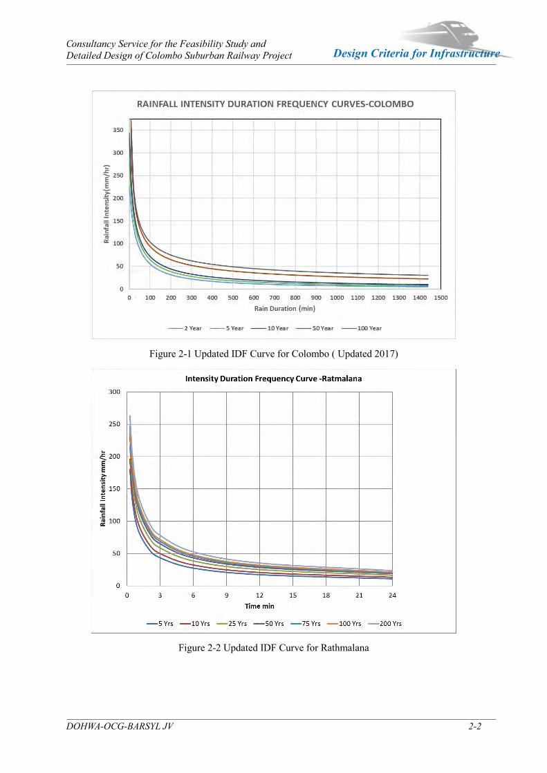
For the computation of the hydraulic structure opening sizes it is very necessary to use Rainfall Intensity Duration Frequency Curves (IDF Curves) available for the principle meteorological stations established close to the proposed railway. The availability of the updated IDF curves is very important as it has been found that because of climate changes the rainfall intensity for short duration rains have been increased during the recent times. Status of available data were examined using the information available in the recent studies. The area of influence by the IDF stations over the proposed railway was determined by standard Thiessen polygons. According to this study it was found that three IDF curves are necessary for the hydrological studies. These IDF curves are Colombo, and Rathmalana
2.1.1.2 The status of these IDF curves
The status of the IDF curves are as follows.
2. Colombo- Was sometime back updated for the Metro Colombo Urban Development Project and the results have been published in a paper Development of IDF Curves for Colombo ENGINEER -Journal Vol. L, No. 01, pp. [page range], 2017, The Institution of Engineers, Sri Lanka by K.D.W. Nandalal and P. Ghnanapala.
3. Rathmalana- Was has been updated using pluviographic data for the proposed Ruwanpura
Railway Project and It was taken from Ruwanpura Railway Hydrological Study Report. This IDF curve has been updated to 2012.
2.1.1.1 IDF Curves
IDF curve for Colombo and Rathmalana which are relevant to the present hydrological study are given in Figures 2-1, 2-2 .
Consultancy Service for the Feasibility Study and Detailed Design of Colombo Suburban Railway Project
DOHWA-OCG-BARSYL JV 2-2
Design Criteria for Infrastructure
Figure 2-1 Updated IDF Curve for Colombo ( Updated 2017)
Figure 2-2 Updated IDF Curve for Rathmalana
Consultancy Service for the Feasibility Study and Detailed Design of Colombo Suburban Railway Project
DOHWA-OCG-BARSYL JV 2-3
Design Criteria for Infrastructure
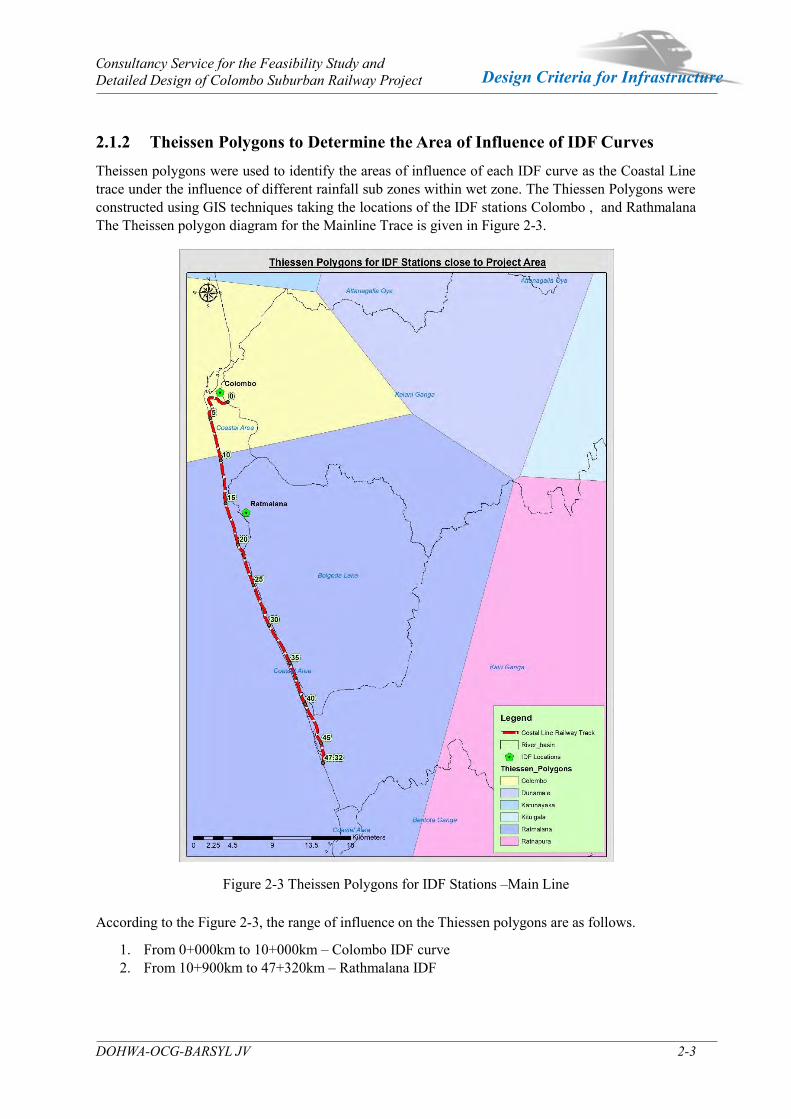
2.1.2 Theissen Polygons to Determine the Area of Influence of IDF Curves Theissen polygons were used to identify the areas of influence of each IDF curve as the Coastal Line trace under the influence of different rainfall sub zones within wet zone. The Thiessen Polygons were constructed using GIS techniques taking the locations of the IDF stations Colombo , and Rathmalana The Theissen polygon diagram for the Mainline Trace is given in Figure 2-3.
Figure 2-3 Theissen Polygons for IDF Stations –Main Line According to the Figure 2-3, the range of influence on the Thiessen polygons are as follows.
1. From 0+000km to 10+000km – Colombo IDF curve 2. From 10+900km to 47+320km – Rathmalana IDF
Consultancy Service for the Feasibility Study and Detailed Design of Colombo Suburban Railway Project
DOHWA-OCG-BARSYL JV 2-4
Design Criteria for Infrastructure
2.1.3 Selected Recurrence Interval (Return Period)
2.1.3.1 General
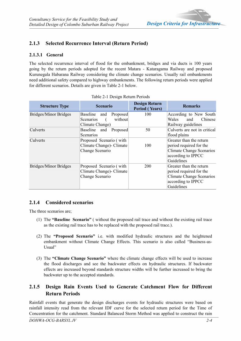
The selected recurrence interval of flood for the embankment, bridges and via ducts is 100 years going by the return periods adopted for the recent Matara - Kataragama Railway and proposed Kurunegala Habarana Railway considering the climate change scenarios. Usually rail embankments need additional safety compared to highway embankments. The following return periods were applied for different scenarios. Details are given in Table 2-1 below.
Table 2-1 Design Return Periods
Structure Type Scenario Design Return Period ( Years) Remarks
Bridges/Minor Bridges Baseline and Proposed Scenarios ( without Climate Change)
100 According to New South Wales and Chinese Railway guidelines
Culverts Baseline and Proposed Scenarios
50 Culverts are not in critical flood plains
Culverts Proposed Scenario ( with Climate Change)- Climate Change Scenario
100
Greater than the return period required for the Climate Change Scenarios according to IPPCC Guidelines
Bridges/Minor Bridges Proposed Scenario ( with Climate Change)- Climate Change Scenario
200 Greater than the return period required for the Climate Change Scenarios according to IPPCC Guidelines
2.1.4 Considered scenarios The three scenarios are;
(1) The “Baseline Scenario” ( without the proposed rail trace and without the existing rail trace as the existing rail trace has to be replaced with the proposed rail trace.).
(2) The “Proposed Scenario” i.e. with modified hydraulic structures and the heightened embankment without Climate Change Effects. This scenario is also called “Business-as-Usual”
(3) The “Climate Change Scenario” where the climate change effects will be used to increase the flood discharges and see the backwater effects on hydraulic structures. If backwater effects are increased beyond standards structure widths will be further increased to bring the backwater up to the accepted standards.
2.1.5 Design Rain Events Used to Generate Catchment Flow for Different
Return Periods Rainfall events that generate the design discharges events for hydraulic structures were based on rainfall intensity read from the relevant IDF curve for the selected return period for the Time of Concentration for the catchment. Standard Balanced Storm Method was applied to construct the rain
Consultancy Service for the Feasibility Study and Detailed Design of Colombo Suburban Railway Project
DOHWA-OCG-BARSYL JV 2-5
Design Criteria for Infrastructure
event histogram for 100-year and 50-Year return periods. The generated design rain events were applied in the hydraulic calculations. 2.1.6 Runoff Coefficients for Rational Method Rational method was used to estimate the design discharge at bridges and culverts where small to medium catchments are applicable. Application of runoff coefficient was needed in computation of the peak discharge where one culvert or a group of consecutive culverts was taken as outlets to a single isolated catchment to which the Rational Formula was applied.
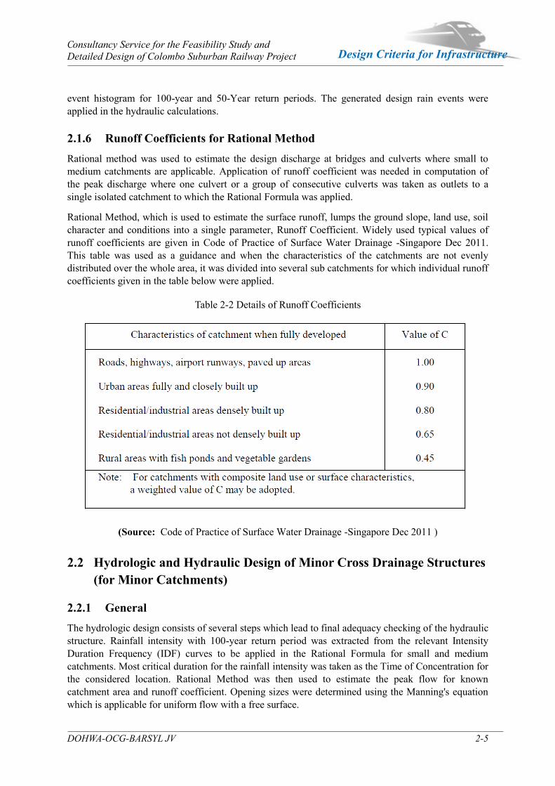
Rational Method, which is used to estimate the surface runoff, lumps the ground slope, land use, soil character and conditions into a single parameter, Runoff Coefficient. Widely used typical values of runoff coefficients are given in Code of Practice of Surface Water Drainage -Singapore Dec 2011. This table was used as a guidance and when the characteristics of the catchments are not evenly distributed over the whole area, it was divided into several sub catchments for which individual runoff coefficients given in the table below were applied.
Table 2-2 Details of Runoff Coefficients
(Source: Code of Practice of Surface Water Drainage -Singapore Dec 2011 )
2.2 Hydrologic and Hydraulic Design of Minor Cross Drainage Structures (for Minor Catchments)
2.2.1 General The hydrologic design consists of several steps which lead to final adequacy checking of the hydraulic structure. Rainfall intensity with 100-year return period was extracted from the relevant Intensity Duration Frequency (IDF) curves to be applied in the Rational Formula for small and medium catchments. Most critical duration for the rainfall intensity was taken as the Time of Concentration for the considered location. Rational Method was then used to estimate the peak flow for known catchment area and runoff coefficient. Opening sizes were determined using the Manning's equation which is applicable for uniform flow with a free surface.
Consultancy Service for the Feasibility Study and Detailed Design of Colombo Suburban Railway Project
DOHWA-OCG-BARSYL JV 2-6
Design Criteria for Infrastructure
2.2.2 Catchment delineation Catchment areas were delineated using 1:10,000 contours from Survey Department, Google satellite imagery and Digital Elevation models purchased from Survey Department or downloaded from the website of the Disaster Management Center (DMC) -riskinfo.lk. In some cases, site knowledge, too was applied.
2.2.3 Selection of Runoff Coefficients Runoff coefficient was taken from Table 2-2. 2.2.4 Computation of Time of concentration (Tc) for Bridges and Cross
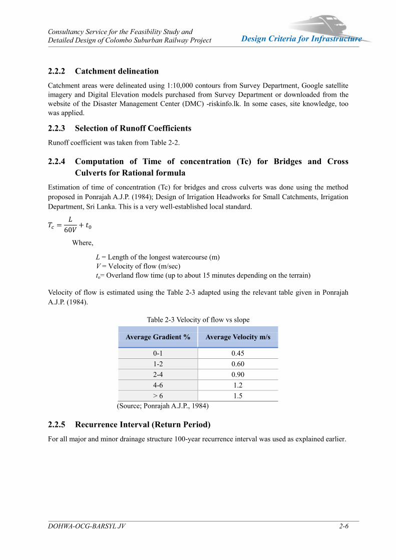
Culverts for Rational formula Estimation of time of concentration (Tc) for bridges and cross culverts was done using the method proposed in Ponrajah A.J.P. (1984); Design of Irrigation Headworks for Small Catchments, Irrigation Department, Sri Lanka. This is a very well-established local standard.
Where,
L = Length of the longest watercourse (m) V = Velocity of flow (m/sec) to= Overland flow time (up to about 15 minutes depending on the terrain)
Velocity of flow is estimated using the Table 2-3 adapted using the relevant table given in Ponrajah A.J.P. (1984).
Table 2-3 Velocity of flow vs slope
Average Gradient % Average Velocity m/s
0-1 0.45 1-2 0.60 2-4 0.90 4-6 1.2 > 6 1.5
(Source; Ponrajah A.J.P., 1984) 2.2.5 Recurrence Interval (Return Period) For all major and minor drainage structure 100-year recurrence interval was used as explained earlier.

Consultancy Service for the Feasibility Study and Detailed Design of Colombo Suburban Railway Project
DOHWA-OCG-BARSYL JV 2-7
Design Criteria for Infrastructure
2.2.6 Computation of Peak flow Once all the parameters have been realistically established, the peak flow Q could be estimated by using the popular Rational Formula.
Q = CIA/360 Where, Q= Peak flow (m3/s) C = Runoff coefficient (dimensionless)
I= Rainfall intensity corresponding to a storm duration equal to time of concentration (mm/hr)
A= Total catchment area (Ha)
This peak flow is taken as the design discharge. 2.2.7 Hydraulic Design of Cross Drainage Structures
2.2.7.1 General
Once the peak flows were estimated, the culvert conveyance capacities were determined through a hydraulic design. Manning’s formula and continuity equation was used for various trial sections to obtain the optimum slope and the section of the culvert. The dimensions were practically fixed to suit the site conditions. The formulas used in conveyance calculations are given as follows:
Continuity equation: Where A = Cross sectional area of flow m2
Q’= Actual Discharge (m3/s) V = Velocity of Flow (m/s)
Manning’s Equation:
⁄ ⁄
Where R = Hydraulic Mean Depth (m) V= Flow velocity (m/s) S = Channel slope n = Manning’s Coefficient (n = 0.02)
Where A= Cross sectional area of flow (m2)
P = Wetted perimeter (m)
Culvert opening designs were performed by selecting trial sections assuming a free board of 10% of the water depth and calculating the actual discharge Q’ and comparing it with the peak flow Q obtained in the hydrologic design. For a satisfactory performance of the culvert Q’>Q. That is the culvert should have a capacity to carry a flow equal or more than the peak flow. Also, the velocity of the flow should preferably be less than 2.0 m/s to avoid scouring at approach and lead-away channels. In few occasional cases when the structure width is large the velocity up to 3.0 m/s was allowed. For Manning’s n, 0.02 were used throughout all the calculations, which represents a condition where the culvert bottom is covered with sediments and the two side walls are made of rough concrete.

Consultancy Service for the Feasibility Study and Detailed Design of Colombo Suburban Railway Project
DOHWA-OCG-BARSYL JV 2-8
Design Criteria for Infrastructure
2.2.8 Regular Factor of Safety of Hydraulic Structures
2.2.8.1 Factor of Safety through Return Period
In the subject of hydrology, the term "Factor of Safety" (usually applied in soil mechanics and structural design) is not generally used instead the Return Period/Recurrent Interval or the Risk is used. Theoretically Risk= 1/Return Period Safety = 1- Risk.
The safety has already been built into the return period. The adopted 100-year period is the practically highest for these types of hydraulic structures. The risk is 1/100*100% = 1% and the safety is 99%. This means that there is only 1% chance that the determined flood level at a hydraulic structure will reach within 100 years. Hence the safety is associated with the reaching of the 100-year specified flood level. Similar risk could be evaluated for 50-Yyear return period.
2.2.8.2 Factor of Safety through Free Board
Since a Free Board has been specified on top of the flood level (i.e. 0.3m for culverts and 1m for bridges) it acts as an additional safety measure. Even if the flood level exceeds the predicted flood level the structure could still occupy the additional flow within the Free Board.
2.2.8.3 Factor of Safety through the Updating the IDF Curve
All hydrologic calculations depend on the Rainfall Intensity Duration Frequency Curves (IDF Curves) and these curves have been updated and used in the studies considering the latest rainfall data reflecting any possible increase of rainfall intensities introducing more safety.
2.2.8.4 Factor of Safety through the extra lengths of structure dimensions
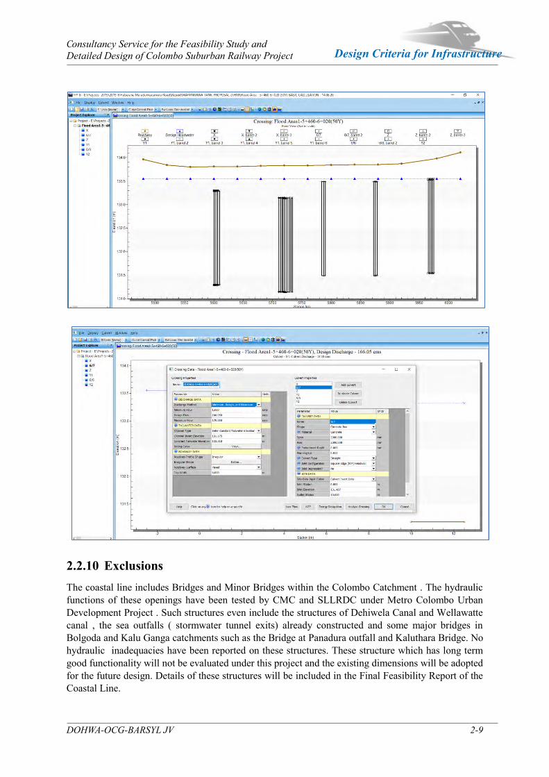
Further safety is naturally introduced when fixing the actual culvert dimensions which are always more than the hydraulic dimensions specified in the hydrology report, especially the total inner height of the culvert opening. For example, if minimum hydraulic dimensions are 1.75mx1.75m a 2mx2m typical culvert size could be used providing higher capacity, i.e. safety. 2.2.9 Evaluating Backwater Effects Backwater effects could be evaluated using HY8 software during the detailed design stage where accurate levels of the culvert inverts , dimensions of upstream and downstream channels track elevations are obtained through level survey. At this stage feasibility backwater effects were not evaluated as no site levels are available. A sample screenshots of the HY8 software interface is given below.
Sample HY8 Software Interface
Consultancy Service for the Feasibility Study and Detailed Design of Colombo Suburban Railway Project
DOHWA-OCG-BARSYL JV 2-9
Design Criteria for Infrastructure
2.2.10 Exclusions The coastal line includes Bridges and Minor Bridges within the Colombo Catchment . The hydraulic functions of these openings have been tested by CMC and SLLRDC under Metro Colombo Urban Development Project . Such structures even include the structures of Dehiwela Canal and Wellawatte canal , the sea outfalls ( stormwater tunnel exits) already constructed and some major bridges in Bolgoda and Kalu Ganga catchments such as the Bridge at Panadura outfall and Kaluthara Bridge. No hydraulic inadequacies have been reported on these structures. These structure which has long term good functionality will not be evaluated under this project and the existing dimensions will be adopted for the future design. Details of these structures will be included in the Final Feasibility Report of the Coastal Line.
3 Alignment Design

Consultancy Service for the Feasibility Study and Detailed Design of Colombo Suburban Railway Project
DOHWA-OCG-BARSYL JV 3-1
Design Criteria for Infrastructure
Alignment Design Chapter 3
3.1 Design Principles
The various parameters for track alignment are defined in accordance with the Sri Lanka Railways authorities, but the selected values are not worse than the maximum (or minimum) limiting values, for the safety related parameters.
Whenever necessary, the track alignment engineer should take into consideration any specific requirements of the appropriate Sri Lanka National Standards and endeavor to use the recommended limiting value specified in the UIC Standard, the European standard , and avoid unnecessary use of maximum (or minimum) limiting values.
About the Maximum cant on curved track in the Northern railway of Sri Lanka is 51
2"(140mm). In the future on Main, Coastal, Puttalam line, the conditions of track and
rolling stock will be better, so that the Consultant recommends 150mm as maximum cant.
For the maximum cant deficiency, the Consultant is to adopt 75 mm which is currently being used and considering the passenger comfort, maintenance and track stability.
3.2 Specifications for Potential Speed on Curves
3.2.1 Cant and Cant defficiency for broad gauge
3.2.1.1 Cant
Cant is the amount by which one rail is raised above the other rail. It is positive when the outer rail on a curved track is raised above inner rail and is negative when the inner rail on a curved track is raised above the outer rail.
Equilibrium Cant is the cant at which the centrifugal force developed during the movement of the vehicle on a curved track is exactly balanced by the cant provided.
The velocity of on the curve has a close relationship with Cant. The Cant and Velocity formula for broad gauge is as follows;
In this figure if p = 0
f = g x tanθ = g x𝐶𝐺
f =𝑣2
𝑅= (
𝑉
3.6)2×
1
𝑅=
𝑉2
12.96𝑅here v( m/sec) = 1
3.6× V(km / hr)
So that 𝑉2
12.96𝑅 = g x𝐶
𝐺
C = 𝑉2
12.96𝑅x𝐺𝑔
= 𝐺
127𝑅𝑉2
Where : G=( Gauge of the track + Width of the rail head ) in mm = 1676 + 74 = 1750
Consultancy Service for the Feasibility Study and Detailed Design of Colombo Suburban Railway Project
DOHWA-OCG-BARSYL JV 3-2
Design Criteria for Infrastructure
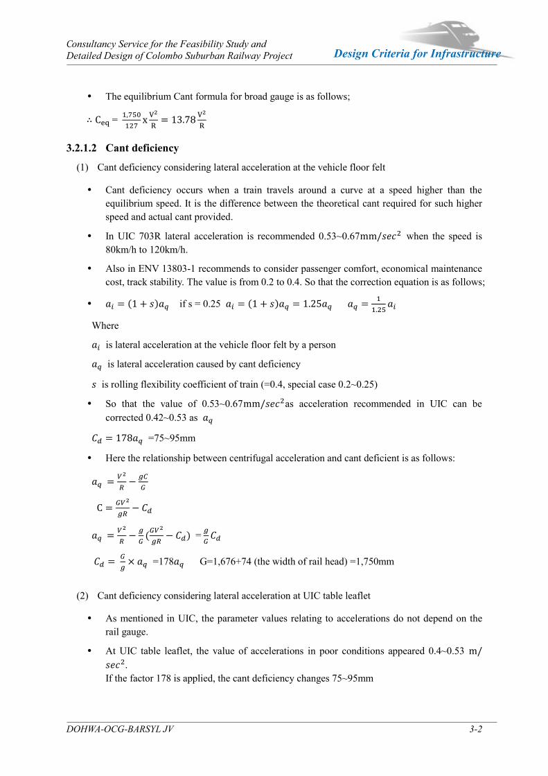
The equilibrium Cant formula for broad gauge is as follows;
∴ Ceq = 1,750
127xV2
R= 13.78
V2
R
3.2.1.2 Cant deficiency
(1) Cant deficiency considering lateral acceleration at the vehicle floor felt
Cant deficiency occurs when a train travels around a curve at a speed higher than the equilibrium speed. It is the difference between the theoretical cant required for such higher speed and actual cant provided.
In UIC 703R lateral acceleration is recommended 0.53~0.67mm/𝑠𝑒𝑐2 when the speed is 80km/h to 120km/h.
Also in ENV 13803-1 recommends to consider passenger comfort, economical maintenance cost, track stability. The value is from 0.2 to 0.4. So that the correction equation is as follows;
𝑎𝑖 = (1 + 𝑠)𝑎𝑞 if s = 0.25 𝑎𝑖 = (1 + 𝑠)𝑎𝑞 = 1.25𝑎𝑞 𝑎𝑞 =1
1.25𝑎𝑖
Where
𝑎𝑖 is lateral acceleration at the vehicle floor felt by a person
𝑎𝑞 is lateral acceleration caused by cant deficiency
𝑠 is rolling flexibility coefficient of train (=0.4, special case 0.2~0.25)
So that the value of 0.53~0.67mm/𝑠𝑒𝑐2as acceleration recommended in UIC can be corrected 0.42~0.53 as 𝑎𝑞
𝐶𝑑 = 178𝑎𝑞 =75~95mm
Here the relationship between centrifugal acceleration and cant deficient is as follows:
𝑎𝑞 =𝑉2
𝑅−
𝑔𝐶
𝐺
C = 𝐺𝑉2
𝑔𝑅− 𝐶𝑑
𝑎𝑞 =𝑉2
𝑅−
𝑔
𝐺(𝐺𝑉2
𝑔𝑅− 𝐶𝑑) = 𝑔
𝐺𝐶𝑑
𝐶𝑑 = 𝐺
𝑔× 𝑎𝑞 =178𝑎𝑞 G=1,676+74 (the width of rail head) =1,750mm
(2) Cant deficiency considering lateral acceleration at UIC table leaflet
As mentioned in UIC, the parameter values relating to accelerations do not depend on the rail gauge.
At UIC table leaflet, the value of accelerations in poor conditions appeared 0.4~0.53 m/𝑠𝑒𝑐2. If the factor 178 is applied, the cant deficiency changes 75~95mm
Consultancy Service for the Feasibility Study and Detailed Design of Colombo Suburban Railway Project
DOHWA-OCG-BARSYL JV 3-3
Design Criteria for Infrastructure
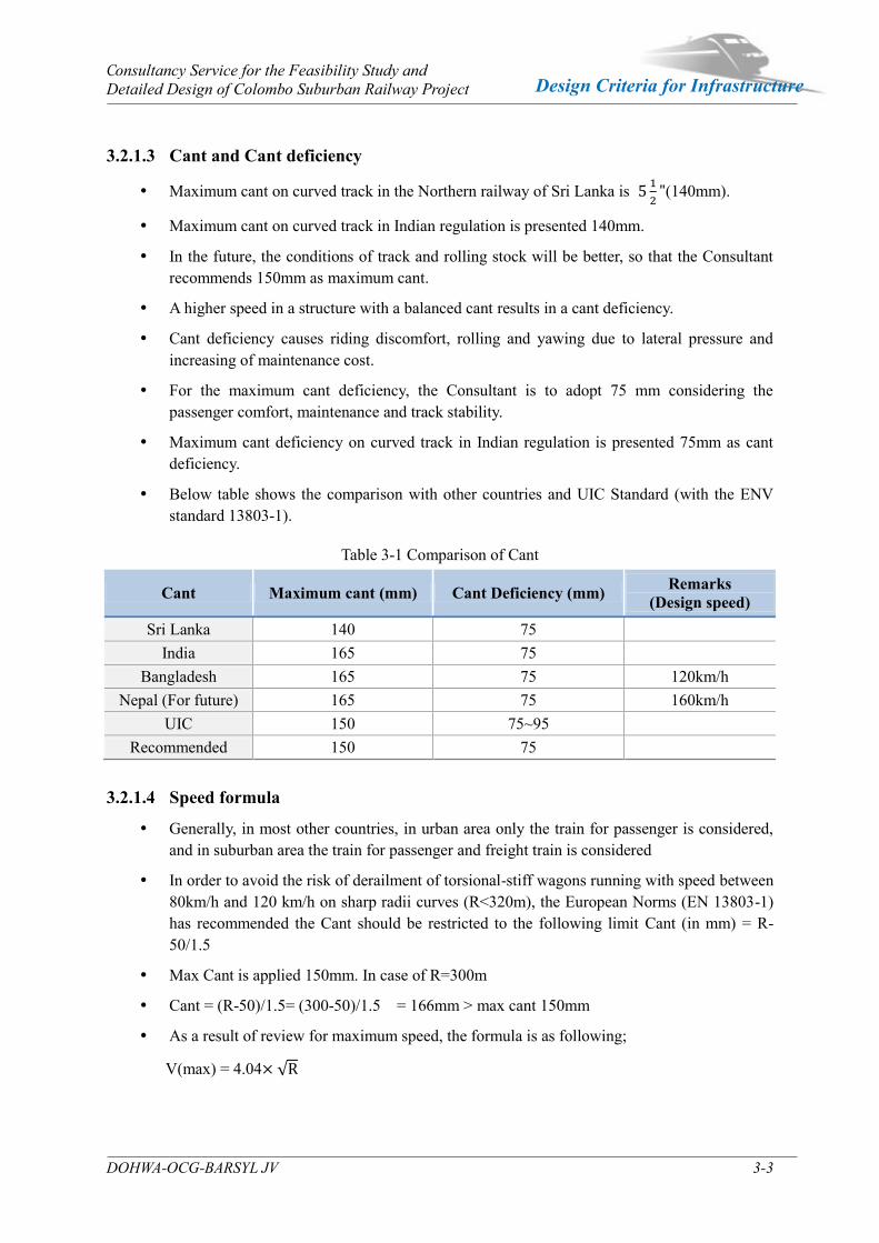
3.2.1.3 Cant and Cant deficiency
Maximum cant on curved track in the Northern railway of Sri Lanka is 5 1
2"(140mm).
Maximum cant on curved track in Indian regulation is presented 140mm.
In the future, the conditions of track and rolling stock will be better, so that the Consultant recommends 150mm as maximum cant.
A higher speed in a structure with a balanced cant results in a cant deficiency.
Cant deficiency causes riding discomfort, rolling and yawing due to lateral pressure and increasing of maintenance cost.
For the maximum cant deficiency, the Consultant is to adopt 75 mm considering the passenger comfort, maintenance and track stability.
Maximum cant deficiency on curved track in Indian regulation is presented 75mm as cant deficiency.
Below table shows the comparison with other countries and UIC Standard (with the ENV standard 13803-1).
Table 3-1 Comparison of Cant
Cant Maximum cant (mm) Cant Deficiency (mm) Remarks (Design speed)
Sri Lanka 140 75 India 165 75
Bangladesh 165 75 120km/h Nepal (For future) 165 75 160km/h
UIC 150 75~95 Recommended 150 75
3.2.1.4 Speed formula
Generally, in most other countries, in urban area only the train for passenger is considered, and in suburban area the train for passenger and freight train is considered
In order to avoid the risk of derailment of torsional-stiff wagons running with speed between 80km/h and 120 km/h on sharp radii curves (R<320m), the European Norms (EN 13803-1) has recommended the Cant should be restricted to the following limit Cant (in mm) = R-50/1.5
Max Cant is applied 150mm. In case of R=300m
Cant = (R-50)/1.5= (300-50)/1.5 = 166mm > max cant 150mm
As a result of review for maximum speed, the formula is as following;
V(max) = 4.04× √R

Consultancy Service for the Feasibility Study and Detailed Design of Colombo Suburban Railway Project
DOHWA-OCG-BARSYL JV 3-4
Design Criteria for Infrastructure
Table 3-2 Result of Maximum Speed
Item Speed formula
Future
-Max Cant=150
-Max Cant Deficiency=75mm
Max Cant is applied150mm Cant = (R-50)/1.5= (300-50)/1.5
= 166mm > 150mm (In case of R=300m)
Cant Deficiency is 75mm Equilibrium cant is 150+ 75 = 225
V(max) = √ 225
13.78× √
=4.04× √
3.2.1.5 Transition Curve
Transition curve shall be provided between a circular curve and straight track or two circular curves. Transition curve serves to be softened the movement between curve and straight track or between two circular curves. The cubic parabola is the usual form of transition curve used on every country such as Sri Lanka, India, Bangladesh, and Nepal.
Desirable length of transition shall be the maximum of the following three values.
L = 0.008𝐶𝑎 × 𝑉𝑚
L = 0.008𝐶𝑑 × 𝑉𝑚
L = 0.72𝐶𝑎
Where L : Length of transition in meters
𝑉𝑚 : Maximum speed in km/h
𝐶𝑎 : Actual cant on curve in mm
𝐶𝑑 : Cant deficiency in mm
1 in 360 relaxations shall apply to Broad Gauge only. For Narrow Gauge and Meter Gauge sections, cant gradient should not be steeper than 1 in 720.
3.2.1.6 Length of Straight track between two horizontal curves
The value for the intermediate length, when based on the principle of the virtual transition, should also conform to the liming values specified in 8.2 of the European Requirement (BS EN 13803-2 8.2).
The minimum length of straight track between two horizontal curves may be determined based on the following formula :
𝑳𝒕 ≥ 𝟎. 𝟓𝑽𝒎𝒂𝒙
Where: -Vmax : Maximum design speed in section, 120km/h
𝐿𝑡 : The distance between two horizontal curves, m.
Consultancy Service for the Feasibility Study and Detailed Design of Colombo Suburban Railway Project
DOHWA-OCG-BARSYL JV 3-5
Design Criteria for Infrastructure
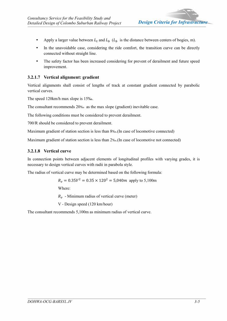
Apply a larger value between 𝐿𝑡 and 𝐿𝑏 (𝐿𝑏 is the distance between centers of bogies, m).
In the unavoidable case, considering the ride comfort, the transition curve can be directly connected without straight line.
The safety factor has been increased considering for prevent of derailment and future speed improvement.
3.2.1.7 Vertical alignment: gradient
Vertical alignments shall consist of lengths of track at constant gradient connected by parabolic vertical curves.
The speed 120km/h max slope is 15‰.
The consultant recommends 20‰ as the max slope (gradient) inevitable case.
The following conditions must be considered to prevent derailment.
700/R should be considered to prevent derailment.
Maximum gradient of station section is less than 8‰.(In case of locomotive connected)
Maximum gradient of station section is less than 2‰.(In case of locomotive not connected)
3.2.1.8 Vertical curve
In connection points between adjacent elements of longitudinal profiles with varying grades, it is necessary to design vertical curves with radii in parabola style.
The radius of vertical curve may be determined based on the following formula:
𝑣 = 0.35𝑉2 = 0.35 × 1202 = 5,040𝑚 apply to 5,100m
Where:
𝑣 - Minimum radius of vertical curve (meter)
V - Design speed (120 km/hour)
The consultant recommends 5,100m as minimum radius of vertical curve.
Consultancy Service for the Feasibility Study and Detailed Design of Colombo Suburban Railway Project
DOHWA-OCG-BARSYL JV 3-6
Design Criteria for Infrastructure
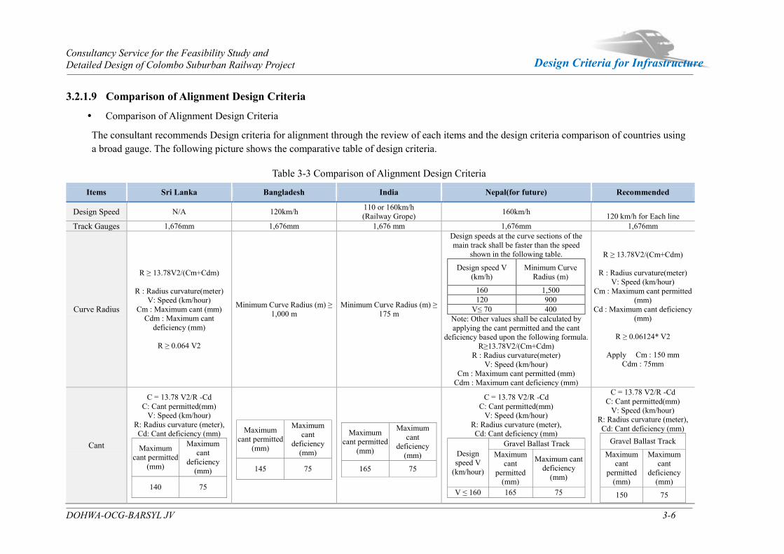
3.2.1.9 Comparison of Alignment Design Criteria
Comparison of Alignment Design Criteria
The consultant recommends Design criteria for alignment through the review of each items and the design criteria comparison of countries using a broad gauge. The following picture shows the comparative table of design criteria.
Table 3-3 Comparison of Alignment Design Criteria
Items Sri Lanka Bangladesh India Nepal(for future) Recommended
Design Speed N/A 120km/h 110 or 160km/h (Railway Grope) 160km/h
120 km/h for Each line Track Gauges 1,676mm 1,676mm 1,676 mm 1,676mm 1,676mm
Curve Radius
R ≥ 13.78V2/(Cm+Cdm)
R : Radius curvature(meter) V: Speed (km/hour)
Cm : Maximum cant (mm) Cdm : Maximum cant
deficiency (mm)
R ≥ 0.064 V2
Minimum Curve Radius (m) ≥ 1,000 m
Minimum Curve Radius (m) ≥ 175 m
Design speeds at the curve sections of the main track shall be faster than the speed
shown in the following table.
Design speed V (km/h)
Minimum Curve Radius (m)
160 1,500 120 900
V≤ 70 400 Note: Other values shall be calculated by applying the cant permitted and the cant
deficiency based upon the following formula. R≥13.78V2/(Cm+Cdm)
R : Radius curvature(meter) V: Speed (km/hour)
Cm : Maximum cant permitted (mm) Cdm : Maximum cant deficiency (mm)
R ≥ 13.78V2/(Cm+Cdm)
R : Radius curvature(meter) V: Speed (km/hour)
Cm : Maximum cant permitted (mm)
Cd : Maximum cant deficiency (mm)
R ≥ 0.06124* V2
Apply Cm : 150 mm
Cdm : 75mm
Cant
C = 13.78 V2/R -Cd C: Cant permitted(mm)
V: Speed (km/hour) R: Radius curvature (meter), Cd: Cant deficiency (mm)
Maximum cant permitted
(mm)
Maximum cant
deficiency (mm)
140 75
Maximum cant permitted
(mm)
Maximum cant
deficiency (mm)
145 75
Maximum cant permitted
(mm)
Maximum cant
deficiency (mm)
165 75
C = 13.78 V2/R -Cd C: Cant permitted(mm)
V: Speed (km/hour) R: Radius curvature (meter), Cd: Cant deficiency (mm)
Design speed V
(km/hour)
Gravel Ballast Track Maximum
cant permitted
(mm)
Maximum cant deficiency
(mm)
V ≤ 160 165 75
C = 13.78 V2/R -Cd C: Cant permitted(mm)
V: Speed (km/hour) R: Radius curvature (meter), Cd: Cant deficiency (mm)
Gravel Ballast Track
Maximum cant
permitted (mm)
Maximum cant
deficiency (mm)
150 75
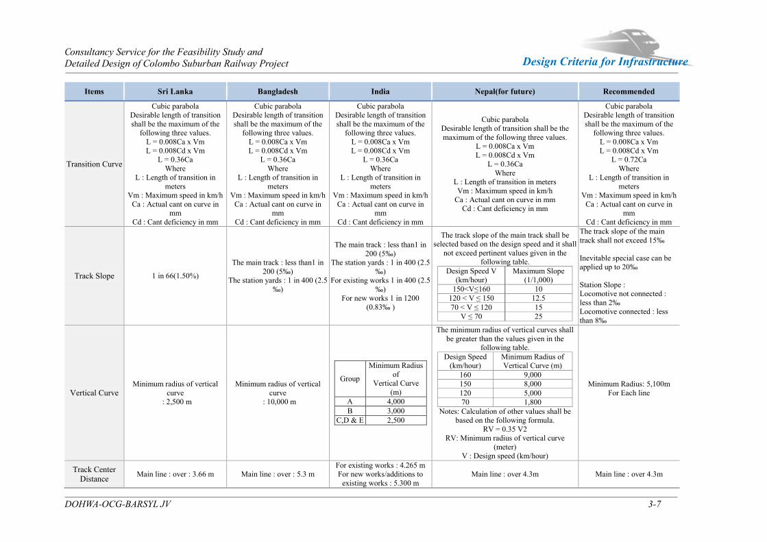
Consultancy Service for the Feasibility Study and Detailed Design of Colombo Suburban Railway Project
DOHWA-OCG-BARSYL JV 3-7
Design Criteria for Infrastructure
Items Sri Lanka Bangladesh India Nepal(for future) Recommended
Transition Curve
Cubic parabola Desirable length of transition shall be the maximum of the
following three values. L = 0.008Ca x Vm L = 0.008Cd x Vm
L = 0.36Ca Where
L : Length of transition in meters
Vm : Maximum speed in km/h Ca : Actual cant on curve in
mm Cd : Cant deficiency in mm
Cubic parabola Desirable length of transition shall be the maximum of the
following three values. L = 0.008Ca x Vm L = 0.008Cd x Vm
L = 0.36Ca Where
L : Length of transition in meters
Vm : Maximum speed in km/h Ca : Actual cant on curve in
mm Cd : Cant deficiency in mm
Cubic parabola Desirable length of transition shall be the maximum of the
following three values. L = 0.008Ca x Vm L = 0.008Cd x Vm
L = 0.36Ca Where
L : Length of transition in meters
Vm : Maximum speed in km/h Ca : Actual cant on curve in
mm Cd : Cant deficiency in mm
Cubic parabola Desirable length of transition shall be the maximum of the following three values.
L = 0.008Ca x Vm L = 0.008Cd x Vm
L = 0.36Ca Where
L : Length of transition in meters Vm : Maximum speed in km/h
Ca : Actual cant on curve in mm Cd : Cant deficiency in mm
Cubic parabola Desirable length of transition shall be the maximum of the
following three values. L = 0.008Ca x Vm L = 0.008Cd x Vm
L = 0.72Ca Where
L : Length of transition in meters
Vm : Maximum speed in km/h Ca : Actual cant on curve in
mm Cd : Cant deficiency in mm
Track Slope 1 in 66(1.50%)
The main track : less than1 in 200 (5‰)
The station yards : 1 in 400 (2.5 ‰)
The main track : less than1 in 200 (5‰)
The station yards : 1 in 400 (2.5 ‰)
For existing works 1 in 400 (2.5 ‰)
For new works 1 in 1200 (0.83‰ )
The track slope of the main track shall be selected based on the design speed and it shall
not exceed pertinent values given in the following table.
Design Speed V (km/hour)
Maximum Slope (1/1,000)
150<V≤160 10 120 < V ≤ 150 12.5 70 < V ≤ 120 15
V ≤ 70 25
The track slope of the main track shall not exceed 15‰ Inevitable special case can be applied up to 20‰ Station Slope : Locomotive not connected : less than 2‰ Locomotive connected : less than 8‰
Vertical Curve Minimum radius of vertical
curve : 2,500 m
Minimum radius of vertical curve
: 10,000 m
Group
Minimum Radius of
Vertical Curve (m)
A 4,000 B 3,000
C,D & E 2,500
The minimum radius of vertical curves shall be greater than the values given in the
following table. Design Speed
(km/hour) Minimum Radius of Vertical Curve (m)
160 9,000 150 8,000 120 5,000 70 1,800
Notes: Calculation of other values shall be based on the following formula.
RV = 0.35 V2 RV: Minimum radius of vertical curve
(meter) V : Design speed (km/hour)
Minimum Radius: 5,100m For Each line
Track Center Distance Main line : over : 3.66 m Main line : over : 5.3 m
For existing works : 4.265 m For new works/additions to
existing works : 5.300 m Main line : over 4.3m Main line : over 4.3m
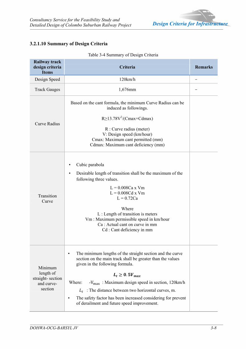
Consultancy Service for the Feasibility Study and Detailed Design of Colombo Suburban Railway Project
DOHWA-OCG-BARSYL JV 3-8
Design Criteria for Infrastructure
3.2.1.10 Summary of Design Criteria
Table 3-4 Summary of Design Criteria Railway track design criteria
Items Criteria Remarks
Design Speed 120km/h -
Track Gauges 1,676mm -
Curve Radius
Based on the cant formula, the minimum Curve Radius can be induced as followings.
R≥13.78V2/(Cmax+Cdmax)
R : Curve radius (meter)
V: Design speed (km/hour) Cmax: Maximum cant permitted (mm)
Cdmax: Maximum cant deficiency (mm)
Transition Curve
• Cubic parabola
• Desirable length of transition shall be the maximum of the following three values.
L = 0.008Ca x Vm L = 0.008Cd x Vm
L = 0.72Ca
Where L : Length of transition is meters
Vm : Maximum permissible speed in km/hour Ca : Actual cant on curve in mm
Cd : Cant deficiency in mm
-
Minimum length of
straight- section and curve-
section
• The minimum lengths of the straight section and the curve section on the main track shall be greater than the values given in the following formula.
𝑳𝒕 ≥ 𝟎. 𝟓𝑽𝒎𝒂𝒙
Where: -Vmax : Maximum design speed in section, 120km/h
𝐿𝑡 : The distance between two horizontal curves, m.
• The safety factor has been increased considering for prevent of derailment and future speed improvement.
-

Consultancy Service for the Feasibility Study and Detailed Design of Colombo Suburban Railway Project
DOHWA-OCG-BARSYL JV 3-9
Design Criteria for Infrastructure
Railway track design criteria
Items Criteria Remarks
Track Slope
• The track slope of the main track shall not exceed 15‰.
• Inevitable special case can be applied up to 20‰
• The following conditions must be considered to prevent derailment. 700/R should be considered to prevent derailment.
• Station Slope : Locomotive not connected : less than 2‰
Locomotive connected : less than 8‰
- -
Vertical Curve
• The minimum radius of vertical curves shall be greater than the values given in the following formula.
• = 0.35 𝑉2
𝑣 : Minimum radius of vertical curve (meter) V : Design speed (km/hour)
• Minimum Radius is 5,100m for Each line
-
Applied design axle load • Passenger and freight train : 22ton
Platform
• ist ce etwee the tr ck ce ter the tf rm 1,700 mm
• i imum tf rm wi th 6m
• tf rm height 1,150mm f rm R. t t f the tf rm
Vertical Clearance from Road Surface
• 5.5 m –Major Roads
• 4.8-5.2 m – Middle Roads
• 4.0-4.8 m – Minor Roads
Clearance from Rail top to overhead structures
• 6.6 m (In general)
• Vertical clearance less than 6.6 m would be treated separately.
4 Stations

Consultancy Service for the Feasibility Study and Detailed Design of Colombo Suburban Railway Project
DOHWA-OCG-BARSYL JV 4-1
Design Criteria for Infrastructure
Stations Chapter 4
4.1 Architecture
4.1.1 General Provisions
4.1.1.1 Design Approach
The design approach of rail station focusing on railway station is as follows.
1) Enhancing the function as local transportation center
i) Securing maximum connectivity with public transportations
ii) Planning proper parking spaces
iii) Planning reasonable traffic square
2) Reformation of space structure
i) Developing station influence areas according to rail station development and taking central role of regional development
ii) Performing the function of pleasant cultural space
iii) Adjacent land utilization and regional characteristics connection
iv) Central role of regional development
v) Consideration of planning nature for securing pleasant cultural and pocket space
3) Conveniences
i) Improve user accessibility and secure cognition
ii) Properly arrange passengers convenient facilities and securing proper spaces
iii) Secure passenger's safety and providing convenience
iv) Secure convenient facilities for the disabled, the old and the infirm, the pregnant and children.
4) Symbolism relief
i) Construction plan securing connectivity with adjacent areas
ii) Shape and structure according with rail station image
iii) Securing plan diversity considering history and tradition if a regional characteristic is strong such as, history ancient-city district, etc.

Consultancy Service for the Feasibility Study and Detailed Design of Colombo Suburban Railway Project
DOHWA-OCG-BARSYL JV 4-2
Design Criteria for Infrastructure
5) Functionality secureness
i) Promoting maintenance efficiency and use convenience by facility modernization and automation
ii) Organizing efficient space according to connectivity and separation at each function and automatic fare collection
6) Sustainable plan and approach setting
i) Introducing environmental friendly plan elements
ii) Facility plan considering sustainable aspect (environment, society, culture)
4.1.2 Programming
4.1.2.1 Site and Traffic Plan
1) General
i) Fundamental Approach
a) Appropriateness of traffic forecast in transportation plan
b) Facility handling capacity analysis including waiting room, pathway, sidewalk, road, etc.
c) Role division with other transportations and connecting transport plan study
d) Regional separation overcome plan study by railway facilities
e) Necessity of connection and access road construction according to rail station construction
f) Appropriateness of type and installation location of traffic safety facilities
ii) Basic concept - Construction of connection traffic network and square and parking plan should be established in order for railway passengers to be comfortable and spend minimum time to access the station.
2) Site Selection
i) The site should be selected as considering accessibility to other areas, connectivity with other transportations based on railway future plan and that regional urban planning. Also, the station for passenger only should be planned to make easy accessibility as considering passenger demand.
ii) Structural condition of grounds in nearby areas should be reviewed.
iii) The decision on size and location of square should be designed for citizen to use conveniently as considering urban planning.
iv) For new rail station, square location should be decided for station location. The relationship between the main structures of station and site should be so selected that the station and platform are at the center of railway yards.
Consultancy Service for the Feasibility Study and Detailed Design of Colombo Suburban Railway Project
DOHWA-OCG-BARSYL JV 4-3
Design Criteria for Infrastructure
v) The station square is desirable to be close to rectangular shape.
vi) Integrated review should be made on environmental conditions (sunshine, wind direction, flooding, water supply, drainage, cultural properties, underground utilities, etc.).
vii) Traffic conditions (accessibility, parking space, public transportation convenience, etc.) should be reviewed.
viii) In the station square, facilities (kiss & ride, bus & ride, taxi & ride, bike & ride) for the function as traffic square should be installed but the site location should be selected to enable public transportation such as bus, etc. accessing to the square by priority.
4.1.2.2 Block Planning
1) Master plan for whole station should be established for efficient development of railway site and individual building and structure should be designed based on the plan.
2) The station and platform should be located at the place where there are many passengers as well as it should have easy access and movement.
3) It should be planned to improve passenger accessibility and movement convenience as connecting station and platform in the plan by considering passenger movement as locating them in the shortest distance.
4) Reviews on urban population changes, station influence area range, passenger changes, train schedule, railway distributions, on-site dwelling, etc. should be made at station planning.
5) Connection with other transportations in the region centered at main floating axis of passenger and platform space is necessary, and it should have holistic relations between waiting room and ticketing window.
6) Passenger movement line should clearly pass through road to platform.
7) It should not include through traffic road.
8) Station should consider arrangement of on-site office, freight space, green belt, etc.
9) Outdoor waiting space and passenger convenient facility should be installed according to the characteristics of station.
10) Square space where many people can wait during massive transportation is planned.
11) The station should be planned to boost city symbolism.
12) The station should satisfy to easily access from both sides at the center of tracks, to have fine view, to minimize movement line without any private road or pedestrian overpass disturbing passenger or freight.
13) Small scale station is largely divided into 3 areas such as square, main building, station, etc., and the station main building should be parallel to the direction of station and track.
14) The arrangement should consider a way station, starting station, final station, track cross station, tourist region, etc.
Consultancy Service for the Feasibility Study and Detailed Design of Colombo Suburban Railway Project
DOHWA-OCG-BARSYL JV 4-4
Design Criteria for Infrastructure
4.1.3 Square Planning
4.1.3.1 Cant
1) For large scale transportation, it should have a size enabling to accommodate enough passengers and citizens.
2) Station square should have cityscape beauty as the place of entering the city and meaning as the symbolic square for the city and local residents.
3) Size and type of station square can be decided depending on station influence area. Hence, new station construction should be proceed after establishing basic development plan of the station influence area.
4) The station square is the pedestrian space for railway passenger and local residents and is required accessibility, convenience, comfort and local symbolism. And it should provide pleasant space by constructing green belt and flower garden around square, and separation of sidewalk from road, mixed use of railway and road, separation of regional traffic from through traffic are necessary.
5) Facilities in square space are sidewalk, parking space, vehicle entrance, flower garden, green belt, elevator, store, information desk, pocket area, passenger convenient facility, various signs and billboards, information board, etc., and they should be installed to get mutually harmonized and characterized.
6) Square of small scale station should be actively utilized as daily life place.
7) Manhole, streetlight, trash can, etc. should be properly arranged with proportional to square size and if necessary, pergola or fountain, etc. can be installed to provide resting area to passenger and local residents.
8) For large scale station, green belt construction should be specially considered and facilities such as clock tower, etc. which are symbolic and cognized to all users can be installed.
9) In the square area, facilities having functions other than through traffic road and traffic control are not included in principle.
10) It should not disturb future reformation plan.
4.1.4 Square Scale Plan
1) Square area calculation - it is calculated based on numbers of passenger in target year, but should consider unique characteristics at each station. It should consider population movements in the station influence area, urban plan scale and developments, etc. Since arrangements of sidewalk, road, green belt, parking space, automobile entrance, etc. are decided by horizontal shape of the square, square area should be reviewed after roughly planning these arrangements.

Consultancy Service for the Feasibility Study and Detailed Design of Colombo Suburban Railway Project
DOHWA-OCG-BARSYL JV 4-5
Design Criteria for Infrastructure
4.1.5 Pedestrian Movement Plan
1) Outside pedestrian movement plan - movement line from outside station to inside station should be reviewed at each user's access means of transportation and reflected to the plan, and followings are major consideration in movement line plan.
i) The path of passengers to enter the station building should be short and safe and should not be dangerous.
ii) The movement of passengers should be horizontal if possible and necessity of facilities such as escalator or elevator, etc. should be provided for vertical movement.
iii) The baggage carriage should be easy for the passengers.
iv) The structure should be convenient for passenger even when the weather is not good by snow, rain, cold, hot, etc.
v) It should consider that passengers can access to the station without crossing heavy traffic roads if possible.
2) Inside pedestrian movement plan
i) It should be arranged so that congested area will not disturb the whole movements inside station.
ii) It should provide clarity of facility to be used by passengers.
iii) Movement line in the platform should be arranged uniformly in order to consider the boarding efficiency on train.
iv) On and off the train movement lines should be separated if possible.
v) Inside pedestrian movement line should be designed as short and simple as possible and should not be detoured or confused.
vi) Pathway for inside movement should be designed to have enough width by considering numbers of pedestrian, ambulation density, walking speed, etc.
vii) It should move horizontally if possible, but should consider convenience to the old and baggage carrying passengers if moving vertically.
4.1.6 Transportation and Parking Plan
1) Transportation plan guideline
i) General
a) As considering unique function and characteristics of each transportation, holistic connection plan between different transportations should be planned by bringing out the best of each of them.
b) Transfer facilities such as bus, taxi, car, bicycle, etc. should be accommodated around square and systematic traffic plan should be established.
Consultancy Service for the Feasibility Study and Detailed Design of Colombo Suburban Railway Project
DOHWA-OCG-BARSYL JV 4-6
Design Criteria for Infrastructure
c) For passenger's convenience, shelters should be installed at bus stop and taxi stand to be able to escape from dazzling by sunlight, snow or rain, and they should harmonize with station building.
d) Transfer movement line should be minimized between station and bus or taxi.
e) Canopy installation should be considered at moving pathway for the convenience of transferring passengers.
ii) Bus & Ride - For smooth connection between bus and station, bus stop should be near the station and the size of bus stop should be designed based on transfer demand.
iii) Kiss & Ride Method
a) It is the way of one family member riding other member to the station by car and the parking facility which has the highest turnover.
b) Installation requirement - it should be located near the main entrance of station, it should be possible for getting in from right side, and have facility for blocking rain or snow. The traffic line for farewell should be one way if possible in Kiss & Ride area.
c) The location of standby parking lot for vehicles to meet passengers should be adjacent to the platform, be easily seen from the exit of station and provide smooth movement line.
iv) Taxi Stand Installation requirement
a) It should be installed near main entrance or square of station for easy access.
b) If it is installed near crossroad, enough weaving distance should be secured.
2) Parking Plan
i) General
a) If the station is located at the place where it is not well connected by public transportation such as subway, bus, etc., enough parking spaces should be secured in consideration of high automobile use rate.
b) Employee parking space should be installed separately from passenger parking space.
c) Bicycle parking space should be separated from vehicle parking space and installed near passenger main entrance if possible.
4.1.7 Shape and Design
4.1.7.1 General
1) Fundamental approach : The design guideline for this railway facility shape and design is applied to plan and design rail station buildings and is to secure convenience, safety and representative symbolism for passenger, administrator and municipal corporation of rail station buildings as not to ignore essential factors and conditions at the planning and designing stage.
2) Applicable scope
i) This guideline is applied to general railway building construction, extension and re-modelling.
Consultancy Service for the Feasibility Study and Detailed Design of Colombo Suburban Railway Project
DOHWA-OCG-BARSYL JV 4-7
Design Criteria for Infrastructure
ii) This guideline is applied to planning and designing of square, concourse, office building and platform which are spatial composition factors of rail station.
iii) Since rail station buildings are different in realization of spatial composition factors depending on the difference between track level and entry layer level, application of guideline should be subdivided into separate types.
iv) Application of the guidelines can be added or weighted according to designer's intention and station's special conditions, but it should be cautioned that the guidelines should not be deleted even though it could not be applied.
3) Basic concept
i) Application Requirements
a) As for cultural-social condition, representative nature as gateway of the region, importance as transportation facility, function satisfaction as public facility is important.
b) As for locational-architectural condition, scale decision according to the location from downtown area, consideration of relations according to track formation and building level and clear space division at each function are important.
ii) Guideline Principles
a) Shape and design in consideration of community characters
As metaphorically embodying mental attributes extracted from local culture, history, industry, etc., it should be considered to acquire monumentality.
It should be considered to apply shape and design factors symbolically realizing community characters with physical characteristics of local culture and history.
It should consider natural factors according to regional location and weather condition.
b) Shape and design in consideration of technology and material
It should consider expression of the spirit of the times as introducing the newest materials presently available in Nepal to railway buildings as public facility.
Building exterior material should be selected for materials having durability and safety and should not apart especially by train vibration.
c) Shape and design satisfying functions as public and cultural facility
Standardized elements should be introduced organizing space for passenger, service and facility of railway station as public facility.
It should be planned according to shape design should consider combined use with other functions such as culture, display, shopping, etc. for improving railway service to passenger.
d) Shape and design considering Reasonable Coloring Plan
Coloring plan should be considered to be effectively applied corresponding to function and exterior and interior characters of the station, and interior color should be specified with close relations with movement line.
Coloring plan should be made to mutually harmonize with material texture, facade color should not be lose unity as well as not be so uniform.
Consultancy Service for the Feasibility Study and Detailed Design of Colombo Suburban Railway Project
DOHWA-OCG-BARSYL JV 4-8
Design Criteria for Infrastructure
4.1.8 Material
4.1.8.1 General
1) Fundamental approach - it is to select materials which are corresponding to use and characteristics of railway buildings, economic, safe and easily maintainable in the future.
2) Application scope - This guideline is applied to railway building design.
4.1.8.2 Material Selection
1) Material selection instruction
i) It should select economic materials having performance required by each space.
ii) As specially considering durability and fire resistance, it should select materials of alleviating site work.
iii) For buildings expected for room structure change or demolition, it should select easily removable materials.
iv) Building interior material should be selected to lighten up atmosphere inside building and have durability.
v) Building exterior material should be selected to express building character and design intention, have strong regional characteristics, durability and weather proof, and it should not be apart by train vibration.
vi) Interior finishing materials should be nonflammable and flame resistant, and especially should consider harmony in interior environment.
vii) Wall should have attachments of various furniture and posts.
viii) Floor should have characters of each room (cable installation, etc.), and select wear resistant materials.
2) Material and construction selection requirement for each part
i) Rooftop - it should be sufficiently equipped with performance and function of water resistant, drainage, durability (durable period), flame resistant, impact resistant, insulation, sound proof, etc.
ii) Wall - it should be sufficiently equipped with performance and function of impact resistant, insulation, sound proof, water resistant, flame resistant, dirt proof, durability, etc.
iii) Floor - it should be sufficiently equipped with performance and function of wear resistant, slippage prevention, dirt proof, water resistant (absorb deformation), flame resistant, impact resistant, color, material quality, etc.
iv) Partition should be corresponded to future change and should select material and construction suitable for application.
v) Ceiling facility should be selected by considering visual effects as facility and space elements such as light, air conditioning, etc.

Consultancy Service for the Feasibility Study and Detailed Design of Colombo Suburban Railway Project
DOHWA-OCG-BARSYL JV 4-9
Design Criteria for Infrastructure
4.1.9 Architecture Design
4.1.9.1 General Requirements for Buildings
1) General
i) Fundamental approach - it should be planned to secure functions suitable for each building use and safety, and to be easily maintained at the same time.
ii) Application scope - it applied to other offices and buildings of station.
iii) Major design considerations
a) Construction inside station and other building should consider harmonization with whole building.
b) New station construction should have design sufficiently reflected by surrounding environments such as regional characteristics, origin name of place, special products, etc.
c) Buildings should be always safe and have planning for easily promptly evacuations at the time of disasters.
d) It should be designed to cope with business change, extension, etc. in future. Especially, station design should consider whole harmony with station and surrounding influence areas allowing for surrounding area development.
e) The design should consider future extension (horizontal and vertical).
f) It should consider weather, climate, characteristics, etc in the region.
g) It should be planned to be creative as focusing on functions well harmonized with each other.
h) It should be designed to be easily maintained as considering problems in maintenance and management.
i) The buildings adjacent to tracks should have measures against train vibration and noise, and should not disturb train operation (during and after construction) considering restrictions of building and train.
j) The design for building of safety installation and important building for train operation should be cautious about protection from fire and flooding damage.
k) Station should be located at the place easily accessed by passengers, and station and platform should be located at the center, if possible.
iv) Other considerations
a) Electricity, water supply facility, etc. should be located at incidental service area (passenger convenience facility).
b) All wall structure except bedroom and kitchen should be designed as flexible type to increase utility of service space.
c) Facility for building maintenance should be reflected to design.(cleaning loop, machinery for internal and external maintenance, etc.)
d) In building layout, surrounding building status, site boundary line, track distribution, etc. should be indicated.
Consultancy Service for the Feasibility Study and Detailed Design of Colombo Suburban Railway Project
DOHWA-OCG-BARSYL JV 4-10
Design Criteria for Infrastructure
e) Major spaces where passengers are mostly using such as waiting room, square, etc. should be planned by pattern design and environmental design if necessary, and should give clear directions with finishing material and lights.
f) When designing station, station signboard should be installed to be harmonized with surroundings and outdoor lighting can be reviewed to enhance cognition if necessary.
2) Substation Building Plan
i) Block planning
a) Optimal system establishment for related facility centralization and worker movement line
b) Facility arrangement plan by improving surrounding environment
c) Reduction of movements by vehicle and pedestrian as arranging nearby entrance of surrounding facilities
d) Building block planning for future extension
e) Equipment carrying plan in consideration of vehicle movement
ii) Circulation planning
a) Specification of worker movement by job characters
b) Work movement optimization by related facility centralization and space arrangement for minimizing management of manpower
iii) Floor design
a) Reasonable unit plan reflecting good working environment improvement and user friendly;
b) Location and floor plan by function and characteristic of each room
c) Unit plan to satisfy changing function and to be easily maintained
d) Construction plan for securing workability and economic feasibility by function of each room
iv) Elevation design
a) Stable design plan to harmonize with surrounding environment
b) Reflection of proper ventilation device
v) Section Design
Floor height plan in consideration of function and equipment height
vi) Landscape Design
Consideration of landscape plan as securing spare space around substation building
Consultancy Service for the Feasibility Study and Detailed Design of Colombo Suburban Railway Project
DOHWA-OCG-BARSYL JV 4-11
Design Criteria for Infrastructure
vii) General requirement for material
Each material is analyzed and applied based on required function and requirements by each facility. Construction and system decision, etc. should be reflected on process planning and specification, and construction materials are selected as comparing their performance with structural characteristics and requirements. Also, they are considered economic feasibility, future maintenance at first.
viii) Material selection Requirement
Maintenance work such as replacing facility and parts or defect repair should be easily done in the future as standardizing facilities and materials between each substation building.
4.1.10 Handicapped Facility
4.1.10.1 General
1) Fundamental approach - Handicapped facility is facilities and equipment for the disabled, the old, the pregnant, etc. to be able to easily move, utilize facilities and access information.
2) Applicable Scope
i) Move convenient facility - This is connection facility for handicapped to move to target building and includes sidewalk, parking lot, outside steps, outside ramps, access road, etc.
ii) Access convenient facility - This includes horizontal and vertical moving spaces from building entrance to access space at each room. Specifically, this includes entrance door, corridor, steps, inside ramps, elevator, etc.
iii) Use convenient facility - This is facility for certain purpose related to rest room or other facility and is must-have space for the handicapped.
3) Basic concept
i) Continuity: This facility should not be disconnected in any place for whole complete circle.
ii) Safety: In all places, it should be moved with safety.
iii) Serviceability: The facility should be used in the most comfortable way.
iv) Generality: It should keep the same conditions for use of general people.
4.1.11 Building Structures
4.1.11.1 Fundamental Approach
Building structure design should be made to provide safe and durable buildings as preventing from deformation, vibration, corrosion or wearing damage, according to international standards EUROCODE, etc.
Consultancy Service for the Feasibility Study and Detailed Design of Colombo Suburban Railway Project
DOHWA-OCG-BARSYL JV 4-12
Design Criteria for Infrastructure
4.1.11.2 Applicable Scope
1) This is applied to new station buildings, building remodeling (repair, maintenance, etc.), building main structure and substructure, temporary structure for various constructions.
2) When designed by special research, etc., these standards may not be applied.
4.1.11.3 Structural Design
1) Structural design instruction - While designing structures, followings should be considered after overall checkup of surrounding conditions such as tracks or railway structures, ground, constructability and operation security, effects on passenger and air, etc.
i) Framework shape should be standard and simple so that it will be dynamically definite structure.
ii) Resistant members to horizontal force should be arranged in the plane without distortion.
iii) Framework should not have detrimental deformation by working load and vibratory damage during walking.
iv) It should be the structure for safe and confident construction.
v) The structure should be as light as possible.
vi) Although some parts or joint area are damaged by unusual loading, the whole structure should not be failed.
4.1.12 Architecture Environment
4.1.12.1 General
1) Basic concept - It should be designed to optimize each performance (heat, air, light, sound) evaluating total factors in relation to architectural environment such as comfort, healthiness, convenience, safety, etc.
4.1.12.2 Thermal Environment
1) Temperature profile - It should be designed to reduce temperature difference between upside and downside by insulating main walls of the room and proper ventilation system so that hot air should not be stagnated around ceiling.
2) Indoor air flow - It should not have wind velocity which occupants cannot sense at heating and should provide freshness as rhythmically changing air within certain range.
3) Heat loss prevention - Windows and doors in living room contacting outside of building with centralized heating and cooling system should have air sealing performance.
4) Condensation prevention
i) Surface condensation prevention
a) Absolute humidity of indoor air should be low.
b) Total resistance of heat transmission in the wall should be increased and wall condensation should be prevented by insulator.
ii) Inside condensation prevention - moisture flux cutoff method should be applied.
Consultancy Service for the Feasibility Study and Detailed Design of Colombo Suburban Railway Project
DOHWA-OCG-BARSYL JV 4-13
Design Criteria for Infrastructure
4.1.12.3 Air Quality
1) Ventilation
i) Ventilation volume and number of ventilation units- Air inflow volume and number of ventilation units for keeping indoor air environment should be provided.
ii) Air filtration plan - Ventilation system should be suitable to building characteristics and should be able to actively respond to partial loading operation considering using time and load variation, etc.
4.1.12.4 Sunlight Environment
1) Lighting method - It should be designed considering contrast and balance with surrounding room or adjacent buildings, and should consider ceiling height, natural lighting, doors on ground, etc.
4.1.12.5 Sound Environment
1) Sound proof and sound absorption plan should be established considering indoor reverberation time and noise level.
2) Dust proof plan
i) Rotary machinery should be selected with low vibration if possible and supported by dust preventive system so that it will absorb vibration energy (amplitude, acceleration, noise).
ii) Ventilation duct should be installed with noise preventing chamber and duct fixing hanger should be independently installed.
iii) Partition wall with reinforcing block should be installed at expansion joints and at regular intervals.
4.1.13 Building Equipment Design
4.1.13.1 General
1) Fundamental approach - It is to be utilized as instructions for comprehending design problems in advance at basic design and working design with considerations of special characteristics of railway buildings on each building facility.
2) Basic Concepts
i) Facility system should be decided according to use of building and its size.
ii) Elevator services should be suitable considering passenger volumes and movement line.
iii) Noise, vibration, etc. generated from various equipment and systems should be regulated within the tolerable limits.
iv) Various facilities should be designed focusing on maintenance and should consider future extension and improvement works.
Consultancy Service for the Feasibility Study and Detailed Design of Colombo Suburban Railway Project
DOHWA-OCG-BARSYL JV 4-14
Design Criteria for Infrastructure
v) Fire-fighting facility at special areas (electric room, transformer room, disaster prevention room, studio, signal room, communication room, etc.) should use eco-friendly extinguishing agent or extinguish equipment.
4.1.13.2 Building Mechanical Facility Design
Facility plan should be reasonable and economic with mutually sufficient discussion to perform same functions as buildings.
1) Air conditioning facility plan - Application scope, conditioning method, machinery combination and arrangement, installation location, size, etc. of air conditioning facility should be sufficiently reviewed.
2) Plumbing system plan - Proper plumbing system should be selected according to the situation.
3) Suppression system plan - It should be cautious to choose mechanical, electrical, fire-fighting equipment and their related parts, they should neither be omitted nor duplicated.
4) Automatic Control Facility Plan
i) It should be able to promptly respond to emergency and have safety and economic feasibility.
ii) It should be suitable for using in the buildings for the purpose and should be operated systematically.
iii) It should be efficiently managed and easily maintained as concentrating on central control room, etc.
5) Elevator service plan - Elevator service (escalator, elevator, etc.) should minimize passenger movement line and secure moving line for handicapped.
6) Ventilation facility plan – Proper ventilation system should be selected according to use of facility.
7) Sewerage Plan
8) Energy saving plan - It should fully consider maintenance with energy savings to reduce cost such as high efficient equipment, water saving, seepage utilization, outdoor air cooling, natural ventilation, etc.
4.1.14 Fire and Evacuation Plan
4.1.14.1 General
1) Fundamental approach - Building design should be reviewed to establish disaster prevention system by introducing prevention concept, minimize casualties during disasters and quickly recover damages from disaster.
2) Disaster related law - Emergency evacuation and disaster prevention facility such as fire, etc. should follow NFPA regulations.

Consultancy Service for the Feasibility Study and Detailed Design of Colombo Suburban Railway Project
DOHWA-OCG-BARSYL JV 4-15
Design Criteria for Infrastructure
4.2 Station Building Electrical Design
The design content includes power supply and distribution system, lighting system, lightning protection and earthing system. 4.2.1 Design
4.2.1.1 General
The normal power supply to station building will be provided by Public Utility Grid. The emergency power supply will be provided by diesel generator set located in station Building. Security of the power supply is important for this development and all design will take this into account to allow adequate redundancy in the event of failure. Low voltage rated: 0.4/0.230kV,50Hz TT system is used for Power Distribution.
4.2.1.2 Applicable design standards and codes
The following design standards and codes will be used in preparing the design of the electrical power distribution system.
BS7671 - Requirements for Electrical Installations
IEE Wiring Regulations 18th Edition, 2018
BS EN 60439 - Specification for low-voltage switchgear and control gear assemblies
BS EN 60947 - Specification of low-voltage switchgear and control gear
BS 62305 –Protection against lightning
BS 7430 –Code of practice for Earthing
BS5266 – Emergency Lighting 4.2.2 Power Supply and Distribution System The electrical supply system will be 400/230V 3-phase, 4-wire 50Hz. The main switchboard will receive power from the dedicated utility transformer (CEB/LECO) and the main switchboards will be constructed to BS EN 60439 Part 1 Form 3 design and type tested assembly. Capacity of transformer & main switch board will be selected to incorporate future solar power generation.
An under-voltage relay will be provided in the main switchboard of incoming cable (normal power cable) to provide signal to emergency diesel generator during the main power failure. Change over from normal supply to diesel generator & vice versa will be automatically or manually.
Molded Case Circuit Breakers (MCCBs) will be adopted in the LV switchboard for safe isolation of incoming feeders. Protection against overload and earth fault will be provided for incoming. Fixed type molded Case Circuit Breakers (MCCBs) and MCBs will be used for protection of finished distribution boards.

Consultancy Service for the Feasibility Study and Detailed Design of Colombo Suburban Railway Project
DOHWA-OCG-BARSYL JV 4-16
Design Criteria for Infrastructure
4.2.3 Lighting The lighting levels for various areas shall be designed generally according to following criteria.
Area Space Lux Level
Pavement Outside Station 150 Entry 200
Public Area & Amenities
Waiting Area(Concourse) 200 Queuing Area 200 Ticket Office 500 Toilets 100 Retail Kiosks 500
Back of House
General Part 150 Station Crew Office 300 Meeting Room 300 Maintenance Room for Track 300 Bedroom 200 Lounge 200 Storage 150 Mechanical Room 200 Electrical Room 200 Operation Control Room 300 Signal Equipment Room 300 Telecom Room 300 Power Supply Room 150 Transformer Room 150 Storage for Elec. 150 Generator Room 150
Circulation
Corridor/ Passage 150 Staircase/ Escalator 150
F.O.B. (Foot Over Bridge) 150
Platform 100 LED type Light fitting will be used for lighting source, Exit signs and directional signs shall be illuminated at all times. Emergency lighting shall be provided by incorporating self-contained battery and conversion kits of 2-hour operation to 5% of existing Light fitting. 4.2.4 Lightning protection and earth system A lightning protection system will be provided to protect the building against lightning strikes. The design of the system will be in accordance with BS62305. Lightning protection system will be incorporated and integrated with the building structure. The design of the earthing and equipotential bonding system will be in accordance with BS7430. Volt free Earth will be provided for Extra Low Voltage System. 4.2.5 Uninterruptible Power Supply (UPS) UPS system will be used to improve the power quality & reliability to essential equipment.
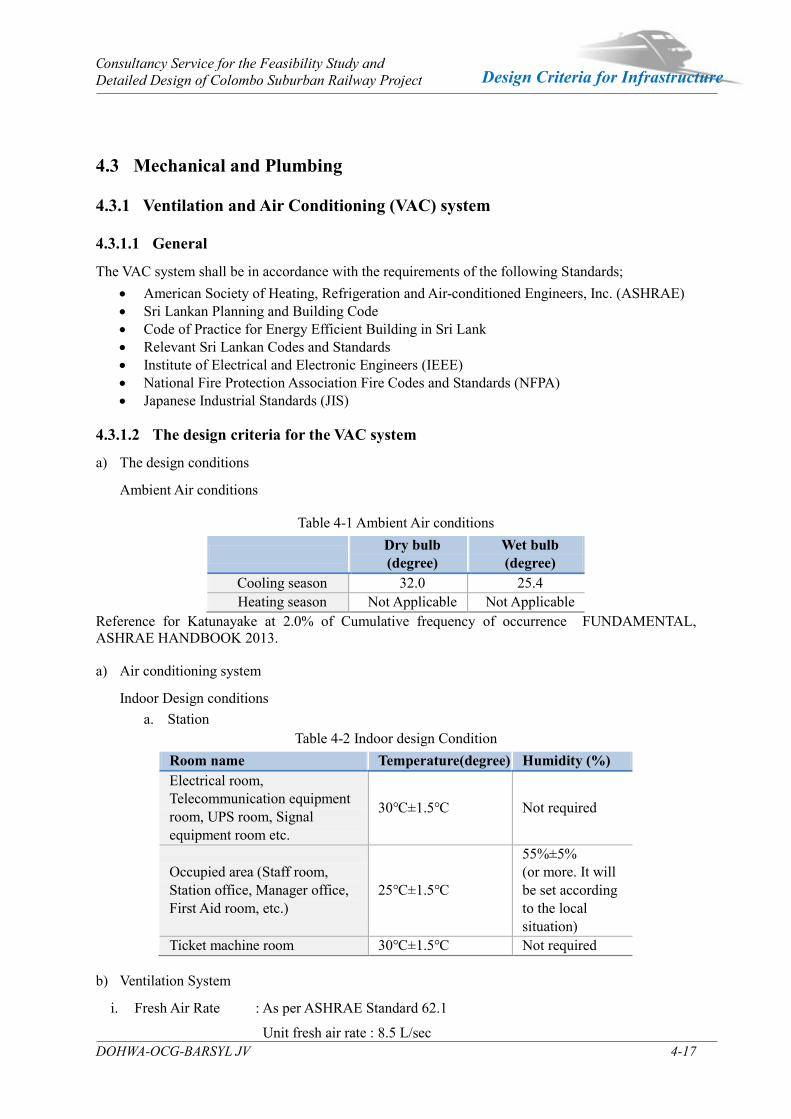
Consultancy Service for the Feasibility Study and Detailed Design of Colombo Suburban Railway Project
DOHWA-OCG-BARSYL JV 4-17
Design Criteria for Infrastructure
4.3 Mechanical and Plumbing
4.3.1 Ventilation and Air Conditioning (VAC) system
4.3.1.1 General
The VAC system shall be in accordance with the requirements of the following Standards; American Society of Heating, Refrigeration and Air-conditioned Engineers, Inc. (ASHRAE) Sri Lankan Planning and Building Code Code of Practice for Energy Efficient Building in Sri Lank Relevant Sri Lankan Codes and Standards Institute of Electrical and Electronic Engineers (IEEE) National Fire Protection Association Fire Codes and Standards (NFPA) Japanese Industrial Standards (JIS)
4.3.1.2 The design criteria for the VAC system
a) The design conditions
Ambient Air conditions
Table 4-1 Ambient Air conditions
Dry bulb (degree)
Wet bulb (degree)
Cooling season 32.0 25.4 Heating season Not Applicable Not Applicable
Reference for Katunayake at 2.0% of Cumulative frequency of occurrence FUNDAMENTAL, ASHRAE HANDBOOK 2013.
a) Air conditioning system
Indoor Design conditions a. Station
Table 4-2 Indoor design Condition Room name Temperature(degree) Humidity (%) Electrical room, Telecommunication equipment room, UPS room, Signal equipment room etc.
30℃±1.5℃ Not required
Occupied area (Staff room, Station office, Manager office, First Aid room, etc.)
25℃±1.5℃
55%±5% (or more. It will be set according to the local situation)
Ticket machine room 30℃±1.5℃ Not required b) Ventilation System
i. Fresh Air Rate : As per ASHRAE Standard 62.1
Unit fresh air rate : 8.5 L/sec
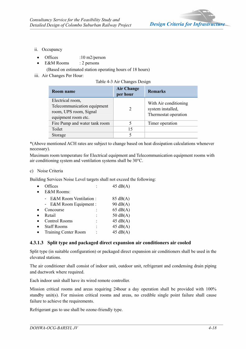
Consultancy Service for the Feasibility Study and Detailed Design of Colombo Suburban Railway Project
DOHWA-OCG-BARSYL JV 4-18
Design Criteria for Infrastructure
ii. Occupancy
Offices :10 m2/person E&M Rooms : 2 persons
(Based on estimated station operating hours of 18 hours) iii. Air Changes Per Hour:
Table 4-3 Air Changes Design
Room name Air Change per hour Remarks
Electrical room, Telecommunication equipment room, UPS room, Signal equipment room etc.
2 With Air conditioning system installed, Thermostat operation
Fire Pump and water tank room 5 Timer operation Toilet 15 Storage 5
*(Above mentioned ACH rates are subject to change based on heat dissipation calculations whenever necessary). Maximum room temperature for Electrical equipment and Telecommunication equipment rooms with air conditioning system and ventilation systems shall be 30°C.
c) Noise Criteria
Building Services Noise Level targets shall not exceed the following: Offices : 45 dB(A) E&M Rooms:
E&M Room Ventilation : 85 dB(A) E&M Room Equipment : 90 dB(A)
Concourse : 65 dB(A) Retail : 50 dB(A) Control Rooms : 45 dB(A) Staff Rooms : 45 dB(A) Training Center Room : 45 dB(A)
4.3.1.3 Split type and packaged direct expansion air conditioners air cooled
Split type (in suitable configuration) or packaged direct expansion air conditioners shall be used in the elevated stations.
The air conditioner shall consist of indoor unit, outdoor unit, refrigerant and condensing drain piping and ductwork where required.
Each indoor unit shall have its wired remote controller.
Mission critical rooms and areas requiring 24hour a day operation shall be provided with 100% standby unit(s). For mission critical rooms and areas, no credible single point failure shall cause failure to achieve the requirements.
Refrigerant gas to use shall be ozone-friendly type.
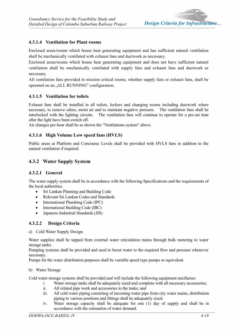
Consultancy Service for the Feasibility Study and Detailed Design of Colombo Suburban Railway Project
DOHWA-OCG-BARSYL JV 4-19
Design Criteria for Infrastructure
4.3.1.4 Ventilation for Plant rooms
Enclosed areas/rooms which house heat generating equipment and has sufficient natural ventilation shall be mechanically ventilated with exhaust fans and ductwork as necessary. Enclosed areas/rooms which house heat generating equipment and does not have sufficient natural ventilation shall be mechanically ventilated with supply fans and exhaust fans and ductwork as necessary. All ventilation fans provided in mission critical rooms, whether supply fans or exhaust fans, shall be operated on an „ALL RUNNING” configuration.
4.3.1.5 Ventilation for toilets
Exhaust fans shall be installed in all toilets, lockers and changing rooms including ductwork where necessary, to remove odors, moist air and to maintain negative pressure. The ventilation fans shall be interlocked with the lighting circuits. The ventilation fans will continue to operate for a pre-set time after the light have been switch off. Air changes per hour shall be as shown the “Ventilations system” above.
4.3.1.6 High Volume Low speed fans (HVLS)
Public areas at Platform and Concourse Levels shall be provided with HVLS fans in addition to the natural ventilation if required.
4.3.2 Water Supply System
4.3.2.1 General
The water supply system shall be in accordance with the following Specifications and the requirements of the local authorities.
Sri Lankan Planning and Building Code Relevant Sri Lankan Codes and Standards International Plumbing Code (IPC) International Building Code (IBC) Japanese Industrial Standards (JIS)
4.3.2.2 Design Criteria
a) Cold Water Supply Design
Water supplies shall be tapped from external water reticulation mains through bulk metering to water storage tanks. Pumping systems shall be provided and used to boost water to the required flow and pressure whenever necessary. Pumps for the water distribution purposes shall be variable speed type pumps or equivalent.
b) Water Storage
Cold water storage systems shall be provided and will include the following equipment ancillaries: i. Water storage tanks shall be adequately sized and complete with all necessary accessories; ii. All related pipe work and accessories to the tanks; and iii. All cold water piping consisting of incoming water pipe from city water mains, distribution
piping to various positions and fittings shall be adequately sized. iv. Water storage capacity shall be adequate for one (1) day of supply and shall be in
accordance with the estimation of water demand.
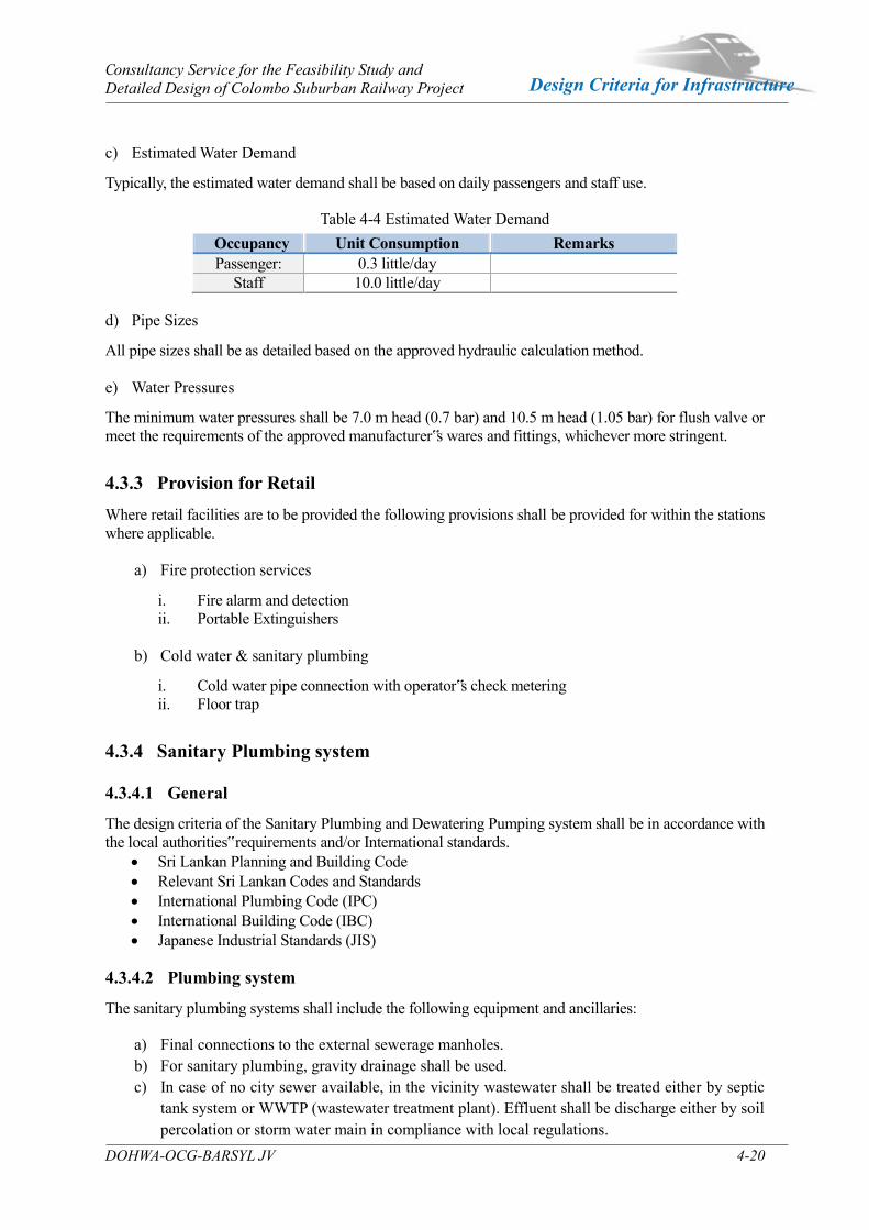
Consultancy Service for the Feasibility Study and Detailed Design of Colombo Suburban Railway Project
DOHWA-OCG-BARSYL JV 4-20
Design Criteria for Infrastructure
c) Estimated Water Demand
Typically, the estimated water demand shall be based on daily passengers and staff use.
Table 4-4 Estimated Water Demand Occupancy Unit Consumption Remarks Passenger: 0.3 little/day
Staff 10.0 little/day d) Pipe Sizes
All pipe sizes shall be as detailed based on the approved hydraulic calculation method. e) Water Pressures
The minimum water pressures shall be 7.0 m head (0.7 bar) and 10.5 m head (1.05 bar) for flush valve or meet the requirements of the approved manufacturer‟s wares and fittings, whichever more stringent.
4.3.3 Provision for Retail Where retail facilities are to be provided the following provisions shall be provided for within the stations where applicable.
a) Fire protection services
i. Fire alarm and detection ii. Portable Extinguishers
b) Cold water & sanitary plumbing
i. Cold water pipe connection with operator‟s check metering ii. Floor trap
4.3.4 Sanitary Plumbing system
4.3.4.1 General
The design criteria of the Sanitary Plumbing and Dewatering Pumping system shall be in accordance with the local authorities‟ requirements and/or International standards.
Sri Lankan Planning and Building Code Relevant Sri Lankan Codes and Standards International Plumbing Code (IPC) International Building Code (IBC) Japanese Industrial Standards (JIS)
4.3.4.2 Plumbing system
The sanitary plumbing systems shall include the following equipment and ancillaries:
a) Final connections to the external sewerage manholes. b) For sanitary plumbing, gravity drainage shall be used. c) In case of no city sewer available, in the vicinity wastewater shall be treated either by septic
tank system or WWTP (wastewater treatment plant). Effluent shall be discharge either by soil percolation or storm water main in compliance with local regulations.
Consultancy Service for the Feasibility Study and Detailed Design of Colombo Suburban Railway Project
DOHWA-OCG-BARSYL JV 4-21
Design Criteria for Infrastructure
Sanitary drainage service including soil, waste and vent systems form the various sanitary fittings.
A fully ventilated one-pipe system with separate vent and soil/waste stacks shall be used.
Waste discharge shall be routed to the external underground manholes of the sewerage reticulation network or treatment plant as applicable.
4.3.4.3 Septic Tank System
Soil and Wastewater will be treated by anaerobic bacteria method; other drain will be direct discharged by gravity to public sewer main by way of manholes. All discharge wastewater quality will be in accordance with Sri Lankan Waste Water quality regulations. The construction of the septic tank and effluent discharge methods shall comply with SLS 745 Part 2: 2009. The Chambers (each tank capacity and calculation) will be in accordance with Design Criteria in details and refer to local standards.
4.3.4.4 Wastewater Treatment Plant
In an event which the construction of a septic tank system for waste water treatment is not practice, a suitable waste water treatment plant may be employed to treat the waste water.
Soil and Wastewater will be treated by aero-bacteria method; other drain will be direct discharged by gravity to public sewer main by way of manholes. All discharge wastewater quality will be in accordance with Sri Lankan Waste Water quality regulations. The Chambers (each tank capacity and calculation) will be in accordance with Design Criteria in details and refer to local requirements. Adopted Effluent Water Standard will follow the National Environmental Act and Regulations by the Central Environmental Authority.
4.3.4.5 Sanitary fixtures
Sanitary fixtures shall conform to the local authority‟s standards and architect requirements. The design criteria of the sanitary fixtures and Drainage system shall be in accordance with the local authorities‟ requirements.
4.3.4.6 Piping pit
The sump pump for submergible type shall be provided the piping pits and elevator pit. The sump pump shall be operated automatic operation by the water level for float ball.
4.3.5 Fire Detection & Protection System The fire detection and protection system shall comply with the CIDA Fire Regulation 3rd Edition or the latest edition. Furthermore, the fire detection and protection system will bear AHJ (Colombo Municipal Council‟s Fire Service Departments, Chief Fire Prevention Officer) approval.
4.3.5.1 Lifts
All lifts should comply with BS EN Standard 81. The main purpose of the lifts in the station is to have barrier free access to the persons with disabilities. Hence the proposed lifts will comply with Persons With Disabilities Act No. 28 of 1996 and other acts and codes stipulated by UDA or client. Also these lifts shall be used in an event of emergency to evacuate PWD‟s and casualty. 4.3.5.2 Escalators
The escalators shall comply have a maximum gradient of 35 degrees. Number of horizontal/pallet run shall be in accordance with BS EN 115-1. All escalators should be rated to work under out door conditions and rated for continuous heavy duty / medium duty categories.

5 Civil / Infrastructure Structures
Consultancy Service for the Feasibility Study and Detailed Design of Colombo Suburban Railway Project
DOHWA-OCG-BARSYL JV 5-1
Design Criteria for Infrastructure
Civil / Infrastructure Structures Chapter 5
5.1 Design Specification for Formation
5.1.1 Summary Designs & Construction of Earthworks (Embankment & cutting section) shall be carried out in accordance with following guidelines & Standards.
ICTAD –(SCA/5-“Standard Specification for Construction and Maintenance of Roads & Bridges”
BS code(BS6031,BS 8006,BS 1377)
AASHTO
General height of the Embankment is 3-5m & width of the embankment is 12m. (Cross section)
General height of a cutting section is also 3-5m except few locations which goes up to 8m.Consequently,earth retaining structures such as gravity retaining wall, soil nail etc. will be proposed due to the restriction of ROW where necessary locations. In addition to that turfing, revetment etc. will be proposed as slope protection methods to avoid erosion. Furthermore, soft ground improvements such as preloading, PVD etc. will be proposed for the locations where the embankment constructs over soft or marshy ground. 5.1.2 Track bed works
5.1.2.1 Embankment Filling
(1) Embankment Layer Thickness
a) Standard thickness of one layer (uncompacted layer thickness) of embankment fill shall not exceed 0.3 m and shall meet compaction regulations.
b) Appropriate thickness of one layer satisfying compaction requirement varies with fill materials, compaction equipment, and compaction frequencies. It must, therefore, be ascertained through a compaction test prior to actual construction.
c) Each successive layer shall be placed only after the previous layer has been tested & found satisfactory.
d) Fill height shall be designed with consideration of given conditions such as bearing ground, topography & geology, fill materials, surrounding environment, construction costs, and maintenance costs.

Consultancy Service for the Feasibility Study and Detailed Design of Colombo Suburban Railway Project
DOHWA-OCG-BARSYL JV 5-2
Design Criteria for Infrastructure
(2) Embankment (Fill) Materials
a) Suitable/unsuitable embankment materials are shown in the following table.
Table 5-1 Embanking materials
Classification Suitable Embankment materials Gravel Track
Unsuitable Embankment materials
Upper trackbed Group A, stabilized Group B, stabilized Group C Group D and soils in Note (1)
Lower trackbed Group A, Group B, Group C Group D and soils in Note (1)
Note (1) : Embankment (Fill) Materials
Expansive soils like bentonite, acid cohesive soil and solfataric clay;
Weathered rocks like serpentinite and mudstone that are well weathered from absorption and expansion;
Soil, which contains highly plastic clay, silt or peat or high-organic soils.
Soil, which contain muck, frozen material, roots, sod or other deleterious matter.
Table 5-2 Classification of fill materials
Group Soils and Rocks
A GW, GP, GW-GM, GP-GM, GW-GC, GP-GC, GM, SW, SW-SM, SP-SM, SW-SC, SP-SC, hard stone mucks/debris (excluding those with high exfoliability/desquamability)
B GC, SP, SM, SC, hard stone mucks (excluding those with high exfoliability/desquamability), soft rock mucks /debris, brittle stone mucks (excluding those classified in Group D)
C ML, CL, organic, coarse grained soils containing fine grained soils
D OL, OH, Pt
※ Maximum size of rock mucks and rock materials shall be 300 mm for lower trackbed and 100 mm for upper trackbed.
b) Embankment & miscellaneous backfill mentioned below shall be in accordance with section304 of SCA/5 –“Standard Specification for Construction & Maintenance of Road & Bridges” & Employer‟s Requirements.
c) Requirements for fill materials for upper and lower track bed shall be in accordance with Sub section 1708 of SCA/5 & Employer‟s Requirements & which are shown in the following table.
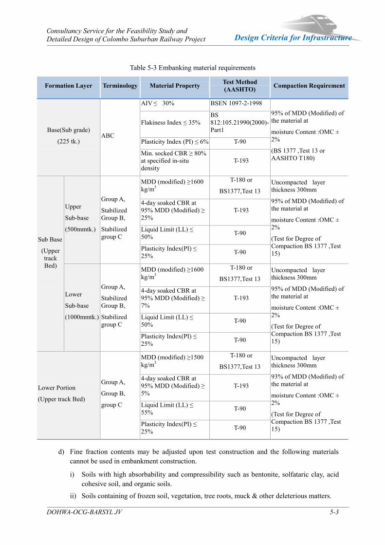
Consultancy Service for the Feasibility Study and Detailed Design of Colombo Suburban Railway Project
DOHWA-OCG-BARSYL JV 5-3
Design Criteria for Infrastructure
Table 5-3 Embanking material requirements
d) Fine fraction contents may be adjusted upon test construction and the following materials
cannot be used in embankment construction.
i) Soils with high absorbability and compressibility such as bentonite, solfataric clay, acid cohesive soil, and organic soils.
ii) Soils containing of frozen soil, vegetation, tree roots, muck & other deleterious matters.
Formation Layer Terminology Material Property Test Method (AASHTO) Compaction Requirement
Base(Sub grade)
(225 tk.) ABC
AIV ≤ 30% BSEN 1097-2-1998 95% of MDD (Modified) of the material at
moisture Content :OMC ± 2%
(BS 1377 ,Test 13 or AASHTO T180)
Flakiness Index ≤ 35% BS 812:105.21990(2000)-Part1
Plasticity Index (PI) ≤ 6% T-90
Min. socked CBR ≥ 80% at specified in-situ density
T-193
Sub Base
(Upper track Bed)
Upper
Sub-base
(500mmtk.)
Group A,
Stabilized Group B,
Stabilized group C
MDD (modified) ≥1600 kg/m3
T-180 or
BS1377,Test 13 Uncompacted layer thickness 300mm
95% of MDD (Modified) of the material at
moisture Content :OMC ± 2%
(Test for Degree of Compaction BS 1377 ,Test 15)
4-day soaked CBR at 95% MDD (Modified) ≥ 25%
T-193
Liquid Limit (LL) ≤ 50% T-90
Plasticity Index(PI) ≤ 25% T-90
Lower
Sub-base
(1000mmtk.)
Group A,
Stabilized Group B,
Stabilized group C
MDD (modified) ≥1600 kg/m3
T-180 or
BS1377,Test 13 Uncompacted layer thickness 300mm
95% of MDD (Modified) of the material at
moisture Content :OMC ± 2%
(Test for Degree of Compaction BS 1377 ,Test 15)
4-day soaked CBR at 95% MDD (Modified) ≥ 7%
T-193
Liquid Limit (LL) ≤ 50% T-90
Plasticity Index(PI) ≤ 25% T-90
Lower Portion
(Upper track Bed)
Group A,
Group B,
group C
MDD (modified) ≥1500 kg/m3
T-180 or
BS1377,Test 13 Uncompacted layer thickness 300mm
93% of MDD (Modified) of the material at
moisture Content :OMC ± 2%
(Test for Degree of Compaction BS 1377 ,Test 15)
4-day soaked CBR at 95% MDD (Modified) ≥ 5%
T-193
Liquid Limit (LL) ≤ 55% T-90
Plasticity Index(PI) ≤ 25% T-90
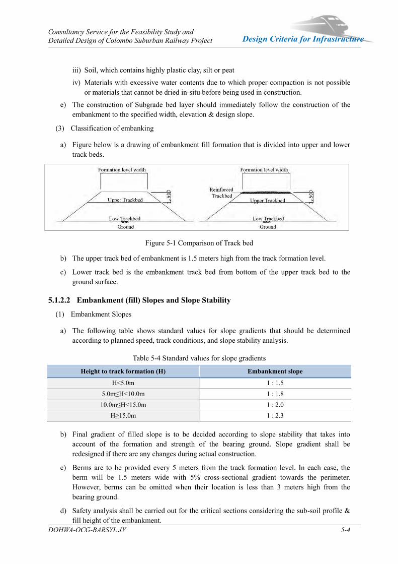
Consultancy Service for the Feasibility Study and Detailed Design of Colombo Suburban Railway Project
DOHWA-OCG-BARSYL JV 5-4
Design Criteria for Infrastructure
iii) Soil, which contains highly plastic clay, silt or peat
iv) Materials with excessive water contents due to which proper compaction is not possible or materials that cannot be dried in-situ before being used in construction.
e) The construction of Subgrade bed layer should immediately follow the construction of the embankment to the specified width, elevation & design slope.
(3) Classification of embanking
a) Figure below is a drawing of embankment fill formation that is divided into upper and lower track beds.
Figure 5-1 Comparison of Track bed
b) The upper track bed of embankment is 1.5 meters high from the track formation level.
c) Lower track bed is the embankment track bed from bottom of the upper track bed to the ground surface.
5.1.2.2 Embankment (fill) Slopes and Slope Stability
(1) Embankment Slopes
a) The following table shows standard values for slope gradients that should be determined according to planned speed, track conditions, and slope stability analysis.
Table 5-4 Standard values for slope gradients
Height to track formation (H) Embankment slope
H<5.0m 1 : 1.5 5.0m≤H<10.0m 1 : 1.8
10.0m≤H<15.0m 1 : 2.0 H≥15.0m 1 : 2.3
b) Final gradient of filled slope is to be decided according to slope stability that takes into
account of the formation and strength of the bearing ground. Slope gradient shall be redesigned if there are any changes during actual construction.
c) Berms are to be provided every 5 meters from the track formation level. In each case, the berm will be 1.5 meters wide with 5% cross-sectional gradient towards the perimeter. However, berms can be omitted when their location is less than 3 meters high from the bearing ground.
d) Safety analysis shall be carried out for the critical sections considering the sub-soil profile & fill height of the embankment.

Consultancy Service for the Feasibility Study and Detailed Design of Colombo Suburban Railway Project
DOHWA-OCG-BARSYL JV 5-5
Design Criteria for Infrastructure
(2) Load cases for Earthwork Analysis & Design
The nominal load due to the live surcharge for the Slope stability analysis shall be in accordance with BS 6031:2009(cl.7.2.3).The Nominal Loading values for the different loading cases are summarized in below table. These values should be applicable for embankment & cut slopes as well.
Table 5-5 Standard load Standard load UDL (kN/m2) Typical applicable design cases
No specified load case 10 Earthwork slopes where maintenance equipment might present an adverse load case
RL 30 Light rail systems
RU 55 Applicable for Sri Lankan Railway conditions
(3) Minimum Safety factor
Standard safety factors for compaction of fill slopes will conform to “Sri Lanka‟s Standards” and following provisions given in the table will apply.
Table 5-6 Standard safety factor for fill slope
Classification Standard
Safety Factor
Remarks
Dry season FS>1.5 Assume no groundwater exists.
Rainy season FS>1.3
There are no special groundwater level conditions for general fill slopes.
On slopes where one side is filled and the other side is cut, the safety factor will be analyzed using measured groundwater level
Earthquake FS>1.1 Seismic momentum force acts in horizontal direction from the
center of embankment soils. Groundwater level is measured level of normal times
Short-term FS>1.1 In cases of short-term, review safety after one year
i) Fill slope design should be reviewed as per safety factors for rainy periods when necessary and also meet safety factors during dry periods.
ii) The allowable Safety factor shall be reduced by 0.1 from the above standard if after analysis strength parameter is found to be not as maximum strength but as residual strength.
iii) The allowable Safety factor shall be increased by 0.05 from the above standard where existing structures such as residential units or building structures are located within zone of failure of the slope‟s upper and lower parts.
iv) Additional analysis shall be carried out when there any foundation of a facility is located within failure range of the slope‟s upper part.
v) Minimum safety factor of 1.1 is applied when above conditions are applied and checked in duplicate and found the safety factor to be FS < 1.1.

Consultancy Service for the Feasibility Study and Detailed Design of Colombo Suburban Railway Project
DOHWA-OCG-BARSYL JV 5-6
Design Criteria for Infrastructure
(4) Excavation &Top soil removal
Specification for the excavation & top soil removal shall be in accordance with section 301,303 & 304.3 of SCA/5 5 –“Standard Specification for Construction & Maintenance of Road & Bridges” & Employer‟s Requirements.
a) Excavation Classification
Excavation of Subgrade shall fall in to the following general classifications.
i) Rock Excavation include all solid rock in place and /or detached pieces of rock of more than 1m3 in volume & large than 300mm in maximum dimensions or compressive strength of 30MPa which cannot be removed unless loosened by any or combination of blasting, welding & dozing. Rock Excavation shall be carried out in accordance with section301.3 of SCA/5 .Where blast required it shall be carried out according to section 306 of SCA/5
ii) Borrow Excavation consists of the excavation and utilization of suitable material required for the construction of embankments or for other portions of the work, obtained from approved source. Borrow Excavation shall be carried out in accordance with section 303 of SCA/5
iii) Excavation of unsuitable/unacceptable material is the removal and disposal of deposits of mixtures of soil which is not suitable for fill as defined in section 301.2(e) of SCA/5.Unsuitable Soil excavation shall be carried out in accordance with section 301.3(e) of SCA/5
b) Removal of top soil & compaction of In-situ soil
Top soil removal shall be in accordance with section 304.3(c) of SCA/ 5 –“Standard Specification for Construction & Maintenance of Road & Bridges” & Employer‟s Requirements.
(5) Placing & Compaction of Embankment Material
Placing & Compaction of Embankment material shall be in accordance with section 304.3 (d & e) of SCA/ 5 –“Standard Specification for Construction & Maintenance of Road & Bridges” & Employer‟s Requirements
a) Upper and lower track beds should be designed to satisfy regulations for compactions of materials and compaction requirements (refer section 6.4.1.1)
b) Compaction on the fill surface in layers should be done to make surface even, achieve the required density up to formation level and form the designed slope.
c) Standard thickness of one layer (uncompacted layer thickness) of embankment fill shall not exceed 0.3 m and shall meet compaction regulations.
d) It should be ensured that longitudinal and lateral cut and fill joining areas are evenly compacted.
e) When relative degree of compaction is determined based on Maximum Dry Density (MDD) at optimum moisture content, the design must require that in-situ and indoor compaction test is conducted and that compaction materials and degree of compaction are suitable for fill conditions.
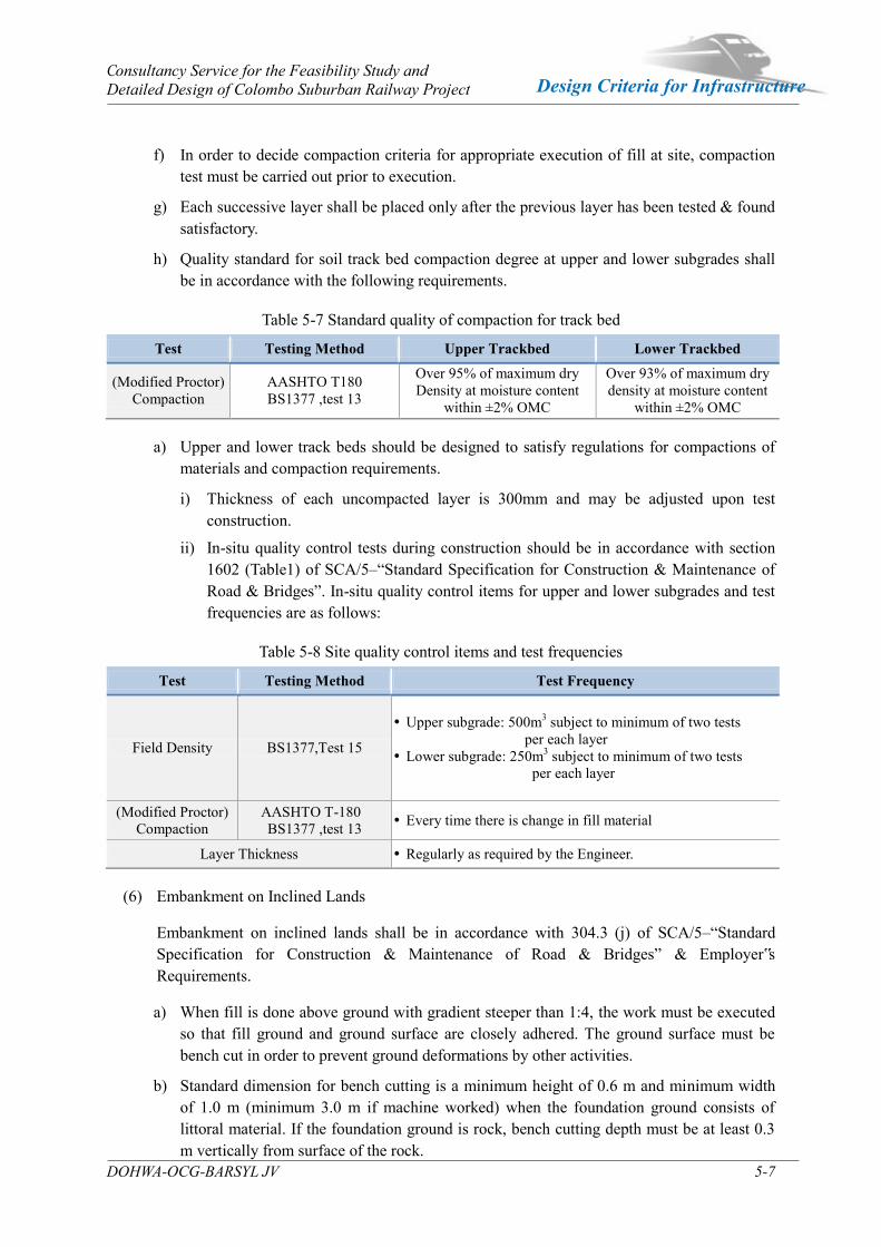
Consultancy Service for the Feasibility Study and Detailed Design of Colombo Suburban Railway Project
DOHWA-OCG-BARSYL JV 5-7
Design Criteria for Infrastructure
f) In order to decide compaction criteria for appropriate execution of fill at site, compaction test must be carried out prior to execution.
g) Each successive layer shall be placed only after the previous layer has been tested & found satisfactory.
h) Quality standard for soil track bed compaction degree at upper and lower subgrades shall be in accordance with the following requirements.
Table 5-7 Standard quality of compaction for track bed
Test Testing Method Upper Trackbed Lower Trackbed
(Modified Proctor) Compaction
AASHTO T180 BS1377 ,test 13
Over 95% of maximum dry Density at moisture content
within ±2% OMC
Over 93% of maximum dry density at moisture content
within ±2% OMC
a) Upper and lower track beds should be designed to satisfy regulations for compactions of materials and compaction requirements.
i) Thickness of each uncompacted layer is 300mm and may be adjusted upon test construction.
ii) In-situ quality control tests during construction should be in accordance with section 1602 (Table1) of SCA/5–“Standard Specification for Construction & Maintenance of Road & Bridges”. In-situ quality control items for upper and lower subgrades and test frequencies are as follows:
Table 5-8 Site quality control items and test frequencies
Test Testing Method Test Frequency
Field Density BS1377,Test 15
Upper subgrade: 500m3 subject to minimum of two tests per each layer
Lower subgrade: 250m3 subject to minimum of two tests per each layer
(Modified Proctor) Compaction
AASHTO T-180 BS1377 ,test 13 Every time there is change in fill material
Layer Thickness Regularly as required by the Engineer.
(6) Embankment on Inclined Lands
Embankment on inclined lands shall be in accordance with 304.3 (j) of SCA/5–“Standard Specification for Construction & Maintenance of Road & Bridges” & Employer‟s Requirements.
a) When fill is done above ground with gradient steeper than 1:4, the work must be executed so that fill ground and ground surface are closely adhered. The ground surface must be bench cut in order to prevent ground deformations by other activities.
b) Standard dimension for bench cutting is a minimum height of 0.6 m and minimum width of 1.0 m (minimum 3.0 m if machine worked) when the foundation ground consists of littoral material. If the foundation ground is rock, bench cutting depth must be at least 0.3 m vertically from surface of the rock.
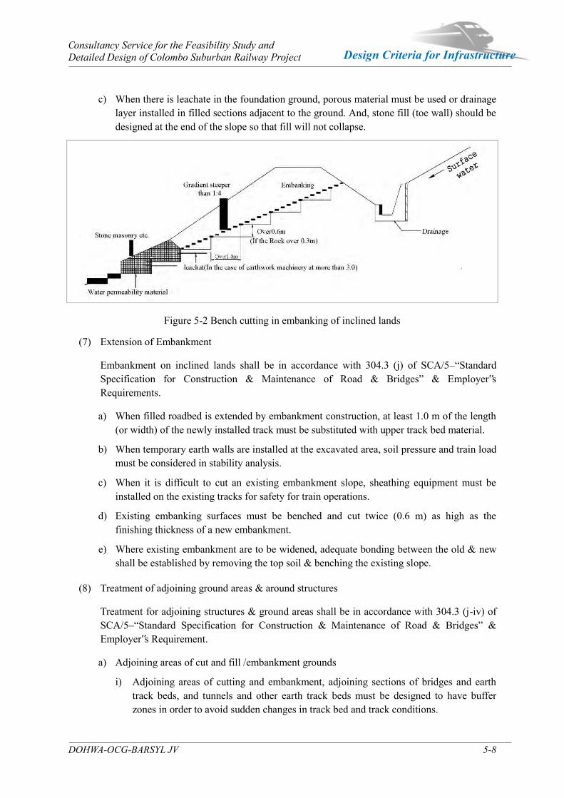
Consultancy Service for the Feasibility Study and Detailed Design of Colombo Suburban Railway Project
DOHWA-OCG-BARSYL JV 5-8
Design Criteria for Infrastructure
c) When there is leachate in the foundation ground, porous material must be used or drainage layer installed in filled sections adjacent to the ground. And, stone fill (toe wall) should be designed at the end of the slope so that fill will not collapse.
Figure 5-2 Bench cutting in embanking of inclined lands
(7) Extension of Embankment
Embankment on inclined lands shall be in accordance with 304.3 (j) of SCA/5–“Standard Specification for Construction & Maintenance of Road & Bridges” & Employer‟s Requirements.
a) When filled roadbed is extended by embankment construction, at least 1.0 m of the length (or width) of the newly installed track must be substituted with upper track bed material.
b) When temporary earth walls are installed at the excavated area, soil pressure and train load must be considered in stability analysis.
c) When it is difficult to cut an existing embankment slope, sheathing equipment must be installed on the existing tracks for safety for train operations.
d) Existing embanking surfaces must be benched and cut twice (0.6 m) as high as the finishing thickness of a new embankment.
e) Where existing embankment are to be widened, adequate bonding between the old & new shall be established by removing the top soil & benching the existing slope.
(8) Treatment of adjoining ground areas & around structures
Treatment for adjoining structures & ground areas shall be in accordance with 304.3 (j-iv) of SCA/5–“Standard Specification for Construction & Maintenance of Road & Bridges” & Employer‟s Requirement.
a) Adjoining areas of cut and fill /embankment grounds
i) Adjoining areas of cutting and embankment, adjoining sections of bridges and earth track beds, and tunnels and other earth track beds must be designed to have buffer zones in order to avoid sudden changes in track bed and track conditions.

Consultancy Service for the Feasibility Study and Detailed Design of Colombo Suburban Railway Project
DOHWA-OCG-BARSYL JV 5-9
Design Criteria for Infrastructure
ii) Ground must be cut to have vertical gradient of less than 1:1.5 and the cut ground must be bench cut.
iii) Approach blocks must be set up at embanking sections when site conditions make cutting difficult.
iv) Drainage ditches must be made, if needed, at cut and fill joining areas.
v) Cross drainages should be installed for drainage to prevent softening of track bed at vertical intersection points (V) where vertical gradients change.
b) Cut on one side and embankment/fill on the other side
i) When formation level is at the junction of cut and fill a sleeper must rest on the ballast on the fill-section only. In order to fulfill this condition at the junction dig out the cut sections further to a minimum of 1 m and refill it with the filling material.
ii) Inclined portions of fill ground shall be excavated as bench cut at 0.6 m height.
iii) Drainage holes must be made when necessary to suit the circumstances.
(9) Base (ABC)
Specification for this section shall be in accordance with Section 405 of SCA/5-“ Standard Specification for Construction & Maintenance of Road & Bridges” & Employer‟s Requirements.
a) Functions and design requirements
i) Base (ABC) must be designed firmly enough to withstand track while at the same time having suitable elasticity for the track and also be designed to prevent softening at the base.
ii) Base (ABC) must disperse loads enough for the upper sub base to withstand and also have water stopping functions to prevent penetration of rain to upper sub base.
iii) Sub grade Bed should be sufficiently compacted that ballast gravel will not penetrate it.
iv) Pore water pressure must not rise even if rainwater penetrates the Base (ABC)
b) Structure
i) Base (ABC) is installed at the top portion within the upper sub base in order to secure rail roadbed bearing capacity.
ii) Drainage layer may be put in, if needed, at base of Base (ABC) of level grounds and cut sections.
c) Width of Subgrade Bed
i) The aggregate base course shall be laid confirming to whole width of standard cross section of Broad Gauge Track in the typical cross section drawing approved by the Engineer.
ii) Gutters, soundproof walls, and safety fences must be designed to be in contact with the Subgrade Bed.
iii) Besides these general matters, matters concerning width and side setting will be designed upon a separate stability examination.
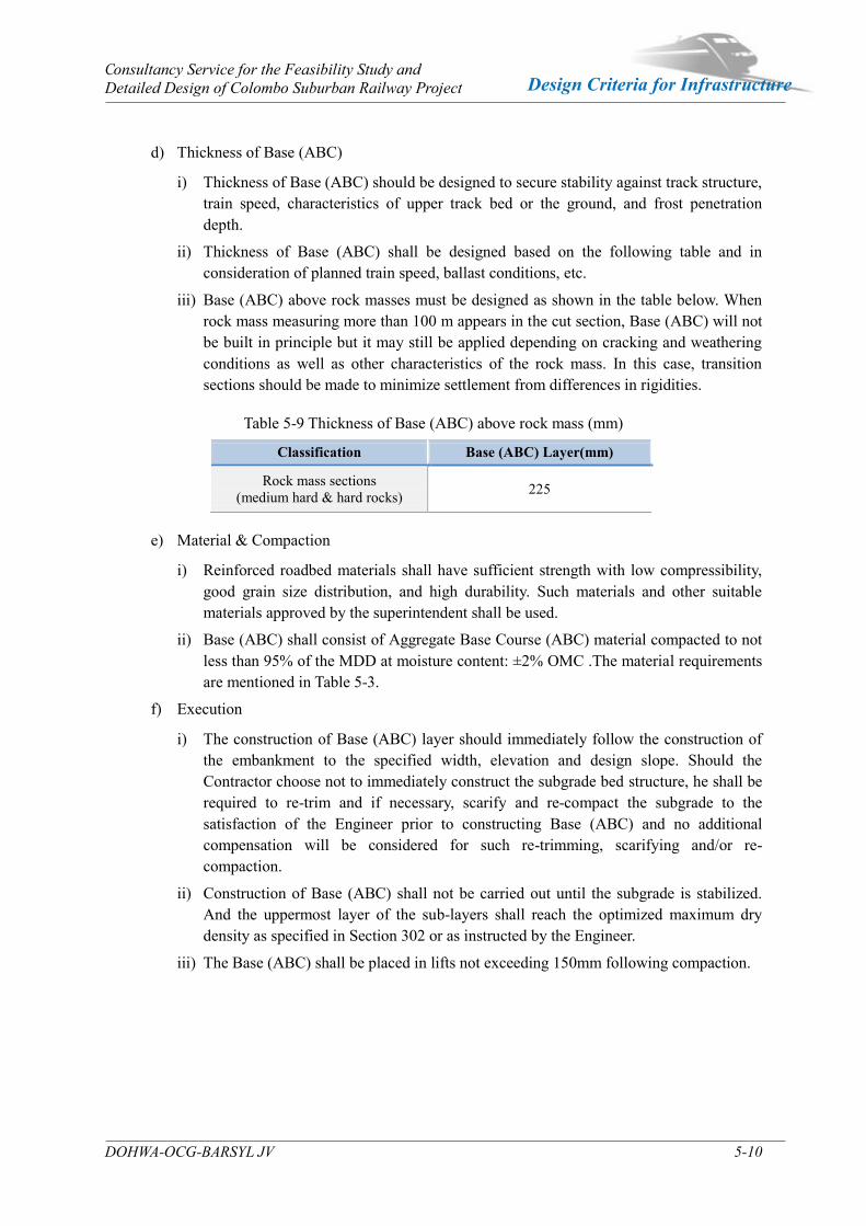
Consultancy Service for the Feasibility Study and Detailed Design of Colombo Suburban Railway Project
DOHWA-OCG-BARSYL JV 5-10
Design Criteria for Infrastructure
d) Thickness of Base (ABC)
i) Thickness of Base (ABC) should be designed to secure stability against track structure, train speed, characteristics of upper track bed or the ground, and frost penetration depth.
ii) Thickness of Base (ABC) shall be designed based on the following table and in consideration of planned train speed, ballast conditions, etc.
iii) Base (ABC) above rock masses must be designed as shown in the table below. When rock mass measuring more than 100 m appears in the cut section, Base (ABC) will not be built in principle but it may still be applied depending on cracking and weathering conditions as well as other characteristics of the rock mass. In this case, transition sections should be made to minimize settlement from differences in rigidities.
Table 5-9 Thickness of Base (ABC) above rock mass (mm)
Classification Base (ABC) Layer(mm)
Rock mass sections (medium hard & hard rocks) 225
e) Material & Compaction
i) Reinforced roadbed materials shall have sufficient strength with low compressibility, good grain size distribution, and high durability. Such materials and other suitable materials approved by the superintendent shall be used.
ii) Base (ABC) shall consist of Aggregate Base Course (ABC) material compacted to not less than 95% of the MDD at moisture content: ±2% OMC .The material requirements are mentioned in Table 5-3.
f) Execution
i) The construction of Base (ABC) layer should immediately follow the construction of the embankment to the specified width, elevation and design slope. Should the Contractor choose not to immediately construct the subgrade bed structure, he shall be required to re-trim and if necessary, scarify and re-compact the subgrade to the satisfaction of the Engineer prior to constructing Base (ABC) and no additional compensation will be considered for such re-trimming, scarifying and/or re-compaction.
ii) Construction of Base (ABC) shall not be carried out until the subgrade is stabilized. And the uppermost layer of the sub-layers shall reach the optimized maximum dry density as specified in Section 302 or as instructed by the Engineer.
iii) The Base (ABC) shall be placed in lifts not exceeding 150mm following compaction.
Consultancy Service for the Feasibility Study and Detailed Design of Colombo Suburban Railway Project
DOHWA-OCG-BARSYL JV 5-11
Design Criteria for Infrastructure
Figure 5-3 Base (ABC) & Ballast Section
(10) Track Ballast
- Sub-ballast layer is the layer that directly bears tracks and should be installed to have
track bed bearing capacity with good drainage.
- Sub-ballast layer is the layer that directly bears tracks and should be installed to have
track bed bearing capacity with good drainage.
- The Ballast layer shall be laid confirming to standard drawing approved by the Engineer.
- Ballast base shall be extended for cant at curved sections and design should take this
widening into consideration.
a) Material
i) Ballast layer material for tracks
- Ballast materials shall have sufficient strength with low compressibility, good grain size
distribution and high durability. Such materials and other suitable materials approved
by the superintendent shall be used.
- The track ballast hard durable crust natural stone, angular sin shape with all dimension
nearly equal. The ballast must be free from dust, chemical contamination & cohesive
particles.
- Ballast materials shall have sufficient strength with low compressibility, good grain size
distribution, and high durability. Such materials and other suitable materials approved
by the superintendent shall be used.
- Coarse aggregates will undergo Bulk Specific Gravity and Absorption Test for Coarse
Aggregates, Los Angeles Abrasion Test for abrasion, and meet criteria in the following
table. Strength Characteristics for Ballast material are given in below table.
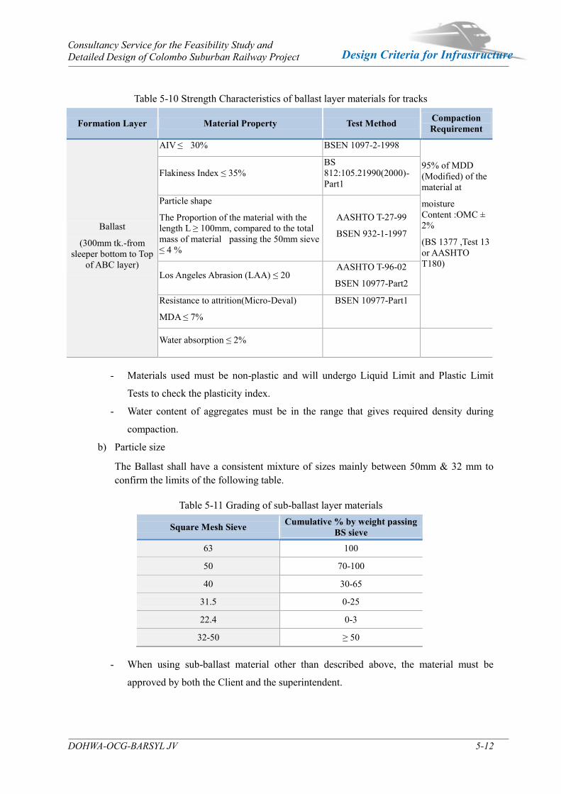
Consultancy Service for the Feasibility Study and Detailed Design of Colombo Suburban Railway Project
DOHWA-OCG-BARSYL JV 5-12
Design Criteria for Infrastructure
Table 5-10 Strength Characteristics of ballast layer materials for tracks
- Materials used must be non-plastic and will undergo Liquid Limit and Plastic Limit
Tests to check the plasticity index.
- Water content of aggregates must be in the range that gives required density during
compaction.
b) Particle size
The Ballast shall have a consistent mixture of sizes mainly between 50mm & 32 mm to confirm the limits of the following table.
Table 5-11 Grading of sub-ballast layer materials
Square Mesh Sieve Cumulative % by weight passing BS sieve
63 100
50 70-100
40 30-65
31.5 0-25
22.4 0-3
32-50 ≥ 50
- When using sub-ballast material other than described above, the material must be
approved by both the Client and the superintendent.
Formation Layer Material Property Test Method Compaction Requirement
Ballast
(300mm tk.-from sleeper bottom to Top
of ABC layer)
AIV ≤ 30% BSEN 1097-2-1998
95% of MDD (Modified) of the material at
moisture Content :OMC ± 2%
(BS 1377 ,Test 13 or AASHTO T180)
Flakiness Index ≤ 35% BS 812:105.21990(2000)-Part1
Particle shape
The Proportion of the material with the length L ≥ 100mm, compared to the total mass of material passing the 50mm sieve ≤ 4 %
AASHTO T-27-99
BSEN 932-1-1997
Los Angeles Abrasion (LAA) ≤ 20 AASHTO T-96-02
BSEN 10977-Part2 Resistance to attrition(Micro-Deval)
MDA ≤ 7%
BSEN 10977-Part1
Water absorption ≤ 2%
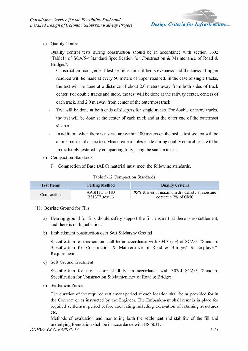
Consultancy Service for the Feasibility Study and Detailed Design of Colombo Suburban Railway Project
DOHWA-OCG-BARSYL JV 5-13
Design Criteria for Infrastructure
c) Quality Control
Quality control tests during construction should be in accordance with section 1602 (Table1) of SCA/5–“Standard Specification for Construction & Maintenance of Road & Bridges”.
- Construction management test sections for rail bed‟s evenness and thickness of upper
roadbed will be made at every 50 meters of upper roadbed. In the case of single tracks,
the test will be done at a distance of about 2.0 meters away from both sides of track
center. For double tracks and more, the test will be done at the railway center, centers of
each track, and 2.0 m away from center of the outermost track.
- Test will be done at both ends of sleepers for single tracks. For double or more tracks,
the test will be done at the center of each track and at the outer end of the outermost
sleeper.
- In addition, when there is a structure within 100 meters on the bed, a test section will be
at one point in that section. Measurement holes made during quality control tests will be
immediately restored by compacting fully using the same material.
d) Compaction Standards
i) Compaction of Base (ABC) material must meet the following standards.
Table 5-12 Compaction Standards
Test Items Testing Method Quality Criteria
Compaction AASHTO T-180 BS1377 ,test 13
95% & over of maximum dry density at moisture content :±2% of OMC
(11) Bearing Ground for Fills
a) Bearing ground for fills should safely support the fill, ensure that there is no settlement, and there is no liquefaction.
b) Embankment construction over Soft & Marshy Ground
Specification for this section shall be in accordance with 304.3 (j-v) of SCA/5–“Standard Specification for Construction & Maintenance of Road & Bridges” & Employer‟s Requirements.
c) Soft Ground Treatment
Specification for this section shall be in accordance with 307of SCA/5–“Standard Specification for Construction & Maintenance of Road & Bridges
d) Settlement Period
The duration of the required settlement period at each location shall be as provided for in the Contract or as instructed by the Engineer. The Embankment shall remain in place for required settlement period before excavating including excavation of retaining structures etc. Methods of evaluation and monitoring both the settlement and stability of the fill and underlying foundation shall be in accordance with BS 6031.

Consultancy Service for the Feasibility Study and Detailed Design of Colombo Suburban Railway Project
DOHWA-OCG-BARSYL JV 5-14
Design Criteria for Infrastructure
(12) Fill slope Protection Methods
a) Slope protection methods must be applied to fill slopes to prevent surface erosion and to strengthen top soil.
b) Compaction fill material, slope size, and other conditions should be considered in choosing the optimum method of protection.
c) Turfing /grass planting shall be in accordance with Section 802 of SCA/5 –“Standard Specification for Construction & Maintenance of Road & Bridges” & Employer‟s Requirements.
Other methods may be adopted depending on site conditions.
(13) Earth Retaining Structures
a) Random Rubble Masonry (RRM) wall shall be in accordance with section 1006 of SCA/5–“Standard Specification for Construction & Maintenance of Road & Bridges” & Employer‟s Requirements.
b) Gravity Retaining wall shall be in accordance with Section 1001,1002 &1008 of Section SCA/5–“Standard Specification for Construction & Maintenance of Road & Bridges” & Employer‟s Requirements
c) Revetment shall be in accordance with Section 804.2 (c& d) ,804.3&804.3/1 of Section SCA/5–“Standard Specification for Construction & Maintenance of Road & Bridges” & Employer‟s Requirements. Stones used in stone revetment method will be hard rocks.
d) Drainage Backfill behind the Earth Retaining Structures shall be in accordance with Section 705 of Section SCA/5–“Standard Specification for Construction & Maintenance of Road & Bridges. Weep-holes for Earth Retaining Structures shall be in accordance with Section 706 of section SCA/5 –“Standard Specification for Construction & Maintenance of Road & Bridges.
e) Slope protection around railway foundations
i) Slope protection must be designed to prevent erosion and collapse from concentrated amounts of water flowing down the slope along utility poles and such in cases of heavy rains.
ii) When utility poles are erected on formation level, rainwater should be induced to flow to the drainage. If needed, paving and border concrete may be used.
iii) When utility pole is installed on the fill slope, ground around the pole should be raised to same level as the formation level and rainwater induced to flow to drainage. Or, slope protection measures such as pitching around the utility pole to avoid slope damage should be taken.
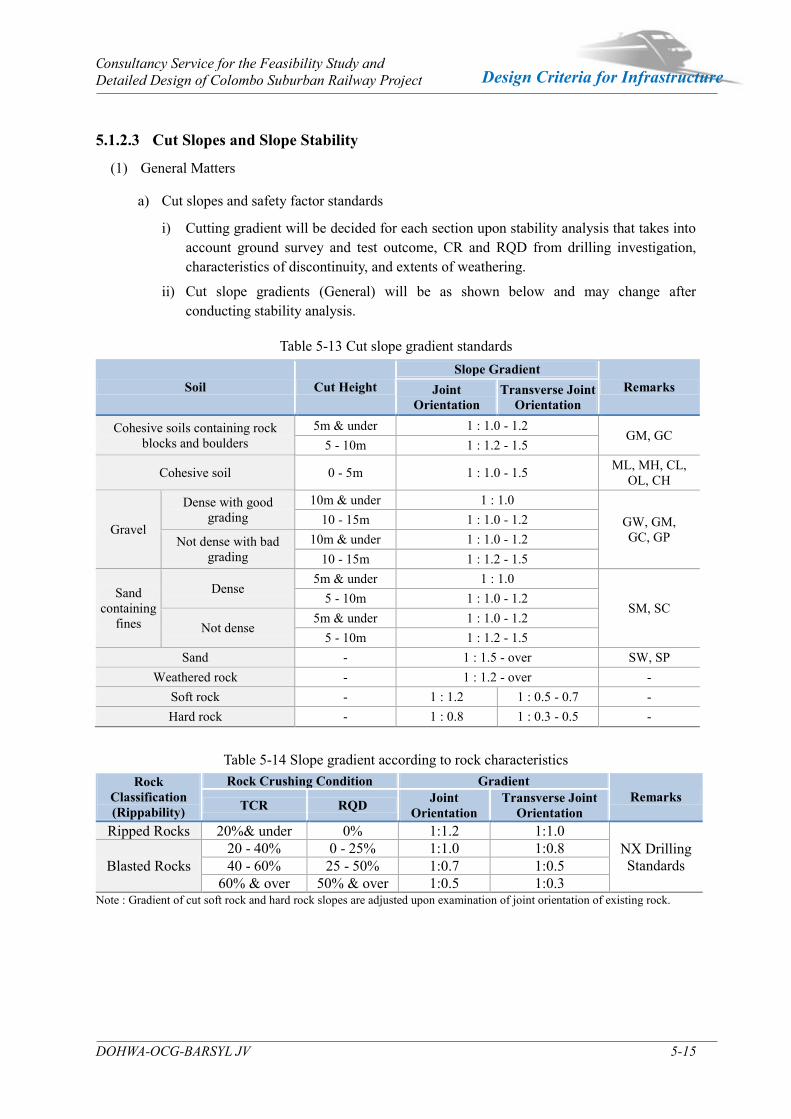
Consultancy Service for the Feasibility Study and Detailed Design of Colombo Suburban Railway Project
DOHWA-OCG-BARSYL JV 5-15
Design Criteria for Infrastructure
5.1.2.3 Cut Slopes and Slope Stability
(1) General Matters
a) Cut slopes and safety factor standards
i) Cutting gradient will be decided for each section upon stability analysis that takes into account ground survey and test outcome, CR and RQD from drilling investigation, characteristics of discontinuity, and extents of weathering.
ii) Cut slope gradients (General) will be as shown below and may change after conducting stability analysis.
Table 5-13 Cut slope gradient standards
Soil Cut Height Slope Gradient
Remarks Joint Orientation
Transverse Joint Orientation
Cohesive soils containing rock blocks and boulders
5m & under 1 : 1.0 - 1.2 GM, GC
5 - 10m 1 : 1.2 - 1.5
Cohesive soil 0 - 5m 1 : 1.0 - 1.5 ML, MH, CL, OL, CH
Gravel
Dense with good grading
10m & under 1 : 1.0 GW, GM, GC, GP
10 - 15m 1 : 1.0 - 1.2 Not dense with bad
grading 10m & under 1 : 1.0 - 1.2
10 - 15m 1 : 1.2 - 1.5
Sand containing
fines
Dense 5m & under 1 : 1.0
SM, SC 5 - 10m 1 : 1.0 - 1.2
Not dense 5m & under 1 : 1.0 - 1.2
5 - 10m 1 : 1.2 - 1.5 Sand - 1 : 1.5 - over SW, SP
Weathered rock - 1 : 1.2 - over - Soft rock - 1 : 1.2 1 : 0.5 - 0.7 - Hard rock - 1 : 0.8 1 : 0.3 - 0.5 -
Table 5-14 Slope gradient according to rock characteristics Rock
Classification (Rippability)
Rock Crushing Condition Gradient Remarks TCR RQD Joint
Orientation Transverse Joint
Orientation Ripped Rocks 20%& under 0% 1:1.2 1:1.0
NX Drilling Standards Blasted Rocks
20 - 40% 0 - 25% 1:1.0 1:0.8 40 - 60% 25 - 50% 1:0.7 1:0.5
60% & over 50% & over 1:0.5 1:0.3 Note : Gradient of cut soft rock and hard rock slopes are adjusted upon examination of joint orientation of existing rock.
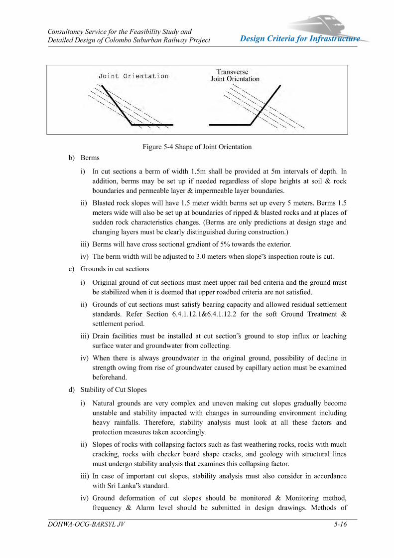
Consultancy Service for the Feasibility Study and Detailed Design of Colombo Suburban Railway Project
DOHWA-OCG-BARSYL JV 5-16
Design Criteria for Infrastructure
Figure 5-4 Shape of Joint Orientation b) Berms
i) In cut sections a berm of width 1.5m shall be provided at 5m intervals of depth. In addition, berms may be set up if needed regardless of slope heights at soil & rock boundaries and permeable layer & impermeable layer boundaries.
ii) Blasted rock slopes will have 1.5 meter width berms set up every 5 meters. Berms 1.5 meters wide will also be set up at boundaries of ripped & blasted rocks and at places of sudden rock characteristics changes. (Berms are only predictions at design stage and changing layers must be clearly distinguished during construction.)
iii) Berms will have cross sectional gradient of 5% towards the exterior.
iv) The berm width will be adjusted to 3.0 meters when slope‟s inspection route is cut.
c) Grounds in cut sections
i) Original ground of cut sections must meet upper rail bed criteria and the ground must be stabilized when it is deemed that upper roadbed criteria are not satisfied.
ii) Grounds of cut sections must satisfy bearing capacity and allowed residual settlement standards. Refer Section 6.4.1.12.1&6.4.1.12.2 for the soft Ground Treatment & settlement period.
iii) Drain facilities must be installed at cut section‟s ground to stop influx or leaching surface water and groundwater from collecting.
iv) When there is always groundwater in the original ground, possibility of decline in strength owing from rise of groundwater caused by capillary action must be examined beforehand.
d) Stability of Cut Slopes
i) Natural grounds are very complex and uneven making cut slopes gradually become unstable and stability impacted with changes in surrounding environment including heavy rainfalls. Therefore, stability analysis must look at all these factors and protection measures taken accordingly.
ii) Slopes of rocks with collapsing factors such as fast weathering rocks, rocks with much cracking, rocks with checker board shape cracks, and geology with structural lines must undergo stability analysis that examines this collapsing factor.
iii) In case of important cut slopes, stability analysis must also consider in accordance with Sri Lanka‟s standard.
iv) Ground deformation of cut slopes should be monitored & Monitoring method, frequency & Alarm level should be submitted in design drawings. Methods of
Consultancy Service for the Feasibility Study and Detailed Design of Colombo Suburban Railway Project
DOHWA-OCG-BARSYL JV 5-17
Design Criteria for Infrastructure
evaluation and monitoring both the settlement underlying foundation and stability of the slope shall be in accordance with BS 6031.
v) Erosion Control
It is necessary to consider minimizing or controlling the erosion & siltation during construction. In such cases, removal & disposal of deposited silt & repair eroded locations as the Engineer may decide are appropriate in the circumstances. Where erosion has occurred on the surface of cuts, the damage shall be made good by backfilling with suitable material and re-trimming. In more serious cases, the slope may have to be cut back & backfilled after benching & compacted to the required standard of compaction with suitable small equipment followed by re-trimming.
e) Spoil Treatment
i) Materials produced from cutting will be tested to determine for possibility of re-use and shall be used as much as possible.
ii) Spoil and surplus soil produced from cutting must be treated appropriately and slope for spoil soil stockpile should be made gentler than 1:2 in sections where spoil work is completed.
iii) Spoil bank should be made stable by reviewing disaster prevention measures that include slope drainage to avoid collapsing due to rain caused soil erosions and runoffs, measures for existing aqueducts, retaining wall protection work, and other environmental impacts.
(2) Cutting and Main Floor
a) Cutting
i) Cut slope forms
- Slope design such as gradient and berm must be decided after topographical and
geotechnical (soil, rocks) studies and considering drainage methods to ensure stability
of cut slopes.
- Shoulder and both ends of cut slope must be arranged to take on smooth rounded
(rounding) forms.
ii) Explosive & Blasting Operation
Explosive & Blasting Operation for rock shall be in accordance with Section 306 of Section SCA/5–“Standard Specification for Construction & Maintenance of Road & Bridges”.
iii) Stability analysis of cut slopes
- Ground‟s given conditions must be thoroughly studied to design gradients and berms
of cut slopes that should fully consider stability and drainage.

Consultancy Service for the Feasibility Study and Detailed Design of Colombo Suburban Railway Project
DOHWA-OCG-BARSYL JV 5-18
Design Criteria for Infrastructure
- In cases where ground conditions have collapse elements or there is a concern for
slope stability to change due to environmental changes after works are completed, a
separate slope stability analysis must be carried out to consider such factors.
iv) Colluvium deposit grounds are often acting as groundwater passages continuously causing problems. Therefore, experimental gradients as given below may be applied.
Table 5-15 Slope gradient on colluvium deposit grounds
Groundwater conditions Gradient
Groundwater level during rainfall is lower than considered in the design 1:1.2
Groundwater level during rainfall rises higher than considered in the design 1:1.5
Groundwater level during normal times is higher than considered in the design 1:1.8 - 1:2.0
- Final gradient of cut slope must be decided after a stability analysis considering ground strength and other factors. When it is found during construction that ground conditions and strengths have changed since the time of design, cut slope gradient must be redesigned.
Table 5-16 Standard safety factor for cutting slope
b) Main Floor
i) Required Criteria and Design
- Main floor must satisfy ground requirement of cut section.
- For cross-sectional drainage at 5% gradient towards rail bed, gutter will be installed on
the original ground and finished evenly. In addition, the ground must be finished by
Classification Standard Safety Factor Remarks
Dry Season FS>1.5 Analyzed as there being no groundwater
Wet Season FS>1.3
For rock slopes, groundwater should be considered at half the depth of tension crack for analysis. For slopes made up of soil layer and weathered rocks, groundwater should be decided by considering site investigation, topographical condition, drainage condition and stability analysis should be carried out
Earthquake FS>1.1 Force of earthquake acts in horizontal direction from the center of destroyed soil body. Groundwater level is measured level of normal times
Short-term FS>1.0 For stability review of less than one 1 year short terms. If assumed strength parameters are not the maximum strength but residual strength: decrease above standard
by 0.1 When there are any existing facilities such as dwellings and buildings within failure zone pof slopes‟ upper
and lower parts: increase by 0.05. When there are foundations of major facilities within failure zone of slope‟s upper part: separate review
needed. When duplicated application of above criteria gives FS < 1.0, apply minimum safety factor of 1.0. When the seismic force is decided, displacement must be allowed and 50% of the horizontal seismic
coefficient must be applied.

Consultancy Service for the Feasibility Study and Detailed Design of Colombo Suburban Railway Project
DOHWA-OCG-BARSYL JV 5-19
Design Criteria for Infrastructure
compaction after cutting is completed because the ground may have been agitated or
loosened by excavation or grading.
- Form of ground has to be decided depending on designs of drainage holes, because
holes are made on the ground or at lateral intersections in normal cases.
ii) Inspection Items
- K30 inspection of evenly finished ground will be done according to Sri Lanka‟s
Standard plate bearing test. Use 300 mm plate to get a value exceeding the necessary
k30 value at each testing location. k30 value measurement is done in the same way as
in compaction fill.
- Testing will be done at every 50 meters sections of construction length.
- To test homogeneity of ground strength, k30 value measurements will be made from 1
to 2 points per track.
- Test will be done at a representative point and whenever it is found that there is a
change in geology conditions within 50 meters.
- Test will be conducted at both ends of the sleeper for single tracks and at the exterior
ends of outermost sleepers and at the center of these sleepers for double or more tracks.
Figure 5-5 Inspection Location
(3) Cut slope Protection Method
a) Slope protection method must be executed on cut slopes to prevent surface erosion, strengthen surface soil, prevent weathering of rocks, and to protect soil and rock slopes.
b) Slope protection method employed will be vegetation or structures to prevent ground from deterioration due to rainfall and erosion or to prevent surface loss even if partial deterioration occurs. Vegetation and structures will be selected in consideration of ground soil quality, execution site, and time.
c) Refer Section 6.4.1.2.(13c-g) for cut slope protection methods.
Consultancy Service for the Feasibility Study and Detailed Design of Colombo Suburban Railway Project
DOHWA-OCG-BARSYL JV 5-20
Design Criteria for Infrastructure
d) Soil Nail
The work shall consist of designing and constructing a permanent soil nail wall and repair of the slope failure using soil-nails and a shotcrete facing. The soil nail shall be carried out in accordance with BS8006-2:2011, BSEN 14490:2010, FHWA-NH1-14-007 or FHWA-SA-96-069R
e) Material and accessories
Soil nails shall be furnished complete in place and with all accessories, and shall be a standard product of a company regularly engaged there manufacture. When required, a certificate of compliances and copies of the certified mill report of the soil nail steel, shall verify that the nails confirm to the requirements of this specification. The soil nails bars & accessories in accordance with Section 2.2 of BS 8006-2 and BS EN 14490:2010
(4) Gyosynthetic material
Gyosynthetic material shall be installed for separation, filtration, and drainage, protection or reinforcement at locations (Embankment & cutting) as instructed by the Engineer. Specification of the material shall be in accordance with Section 1710, 2000 of SCA/5 –“Standard Specification for Construction & Maintenance of Road & Bridges.
Consultancy Service for the Feasibility Study and Detailed Design of Colombo Suburban Railway Project
DOHWA-OCG-BARSYL JV 5-21
Design Criteria for Infrastructure
5.2 Geotechnical Design
5.2.1 References Below references were used to establish the Geotechnical design criteria of the project.
(1) Guidelines for interpretation of site investigation data for estimating the carrying capacity of single piles for design of bored and cast in-situ reinforced concrete piles -ICTAD publication.
(2) Pile Design and Construction Practice by M J Tomlinson
(3) Specifications for bored and cast insitu reinforced concrete piles – CIDA (ICTAD) publication
(4) Foundation design and construction- GEO PUBLICATION No. 1/2006
(5) Foundation Analysis and Design-J.E Bowels
(6) Foundation design and construction-MJ Tomlinson 5.2.2 Estimation of Soil Parameters
5.2.2.1 Estimation of corrected N value (N70)
Corrected N value N70 can be estimated as per the equation below.
N70 = CN x N x ƞ1 x ƞ2 x ƞ3 x ƞ4 (3-3, p-158- Foundation Analysis and Design J.E Bowels)
Where;
ƞ1= Hammer correction, Er=55% use for Sri Lanka
ƞ2= Rod length correction
ƞ3= Sampler correction
ƞ4 = Borehole diameter correction
5.2.2.2 Estimation of shear strength parameters of soil
Friction angle of granular soils (Ф) can be estimated as follows;
Ф=0.36N70+27 (3-5, p-163-Foundation Analysis and Design J.E Bowels)
Un-drained shear strength of cohesive soils can be estimated as follows;
qu=kN70(3-9, p-165-Foundation Analysis and Design J.E Bowels)
Where; k=12
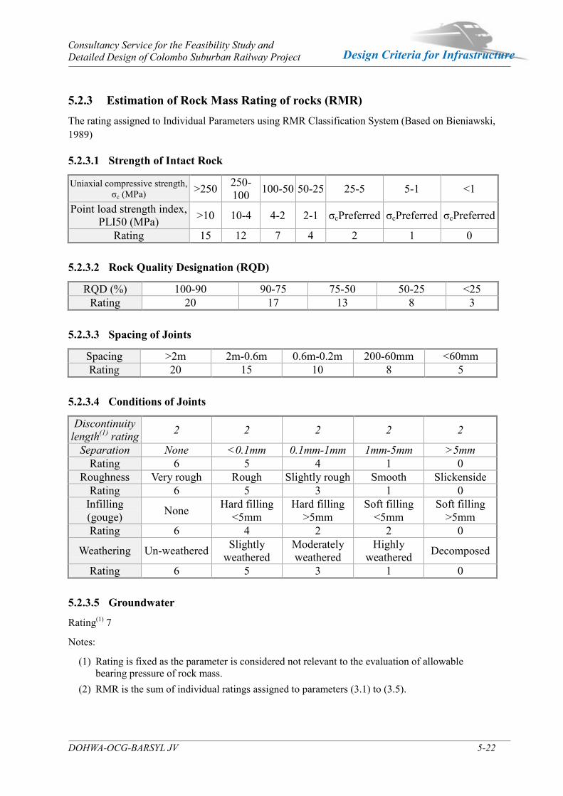
Consultancy Service for the Feasibility Study and Detailed Design of Colombo Suburban Railway Project
DOHWA-OCG-BARSYL JV 5-22
Design Criteria for Infrastructure
5.2.3 Estimation of Rock Mass Rating of rocks (RMR) The rating assigned to Individual Parameters using RMR Classification System (Based on Bieniawski, 1989)
5.2.3.1 Strength of Intact Rock
Uniaxial compressive strength, σc (MPa) >250 250-
100 100-50 50-25 25-5 5-1 <1
Point load strength index, PLI50 (MPa) >10 10-4 4-2 2-1 σcPreferred σcPreferred σcPreferred
Rating 15 12 7 4 2 1 0
5.2.3.2 Rock Quality Designation (RQD)
RQD (%) 100-90 90-75 75-50 50-25 <25 Rating 20 17 13 8 3
5.2.3.3 Spacing of Joints
Spacing >2m 2m-0.6m 0.6m-0.2m 200-60mm <60mm Rating 20 15 10 8 5
5.2.3.4 Conditions of Joints
Discontinuity length(1) rating 2 2 2 2 2
Separation None <0.1mm 0.1mm-1mm 1mm-5mm >5mm Rating 6 5 4 1 0
Roughness Very rough Rough Slightly rough Smooth Slickenside Rating 6 5 3 1 0
Infilling (gouge) None Hard filling
<5mm Hard filling
>5mm Soft filling
<5mm Soft filling
>5mm Rating 6 4 2 2 0
Weathering Un-weathered Slightly weathered
Moderately weathered
Highly weathered Decomposed
Rating 6 5 3 1 0
5.2.3.5 Groundwater
Rating(1) 7
Notes:
(1) Rating is fixed as the parameter is considered not relevant to the evaluation of allowable bearing pressure of rock mass.
(2) RMR is the sum of individual ratings assigned to parameters (3.1) to (3.5).
Consultancy Service for the Feasibility Study and Detailed Design of Colombo Suburban Railway Project
DOHWA-OCG-BARSYL JV 5-23
Design Criteria for Infrastructure
5.2.4 Estimation of carrying capacity of pile
5.2.4.1 Estimation of ultimate skin friction of bored piles
Estimation of fu;
In Sand: fu=1.3N kPacl 4.2.2 of ICTAD/DEV/15_2011
In Clays: fu=αCu kPacl 4.3 of ICTAD/DEV/15_2011
Negative: fu= β P(z) kPacl 5.0 of ICTAD/DEV/15_2011
In Weathered Rock: fu= 2*SPT Ncl 4.5 of ICTAD/DEV/15_2011
In Rock: fu=αβquccl 4.5 of ICTAD/DEV/15_2011
Note:
(1) The mobilized rock socket friction depends on the construction methodology and in general 25% of the estimated rock socket friction is assumed to be mobilized, if bentonite slurry is used to stabilize the pile bore.
(2) The contribution to the skin friction from overburden soil is negligible if bentonite slurry is used to stabilize the pile bore.
5.2.4.2 Estimation of ultimate end resistance of bored piles
Estimation of qu
For soils based on SPT: qult(net) = 40 Ncl3.1.2 of ICTAD/DEV/15_2011
For Clays based on Cu: qult(net) = 9Cucl 3.2 of ICTAD/DEV/15_2011
For Rocks: use the chart of allowable end bearing capacity for igneous and metamorphic rocks as per the figure G-1 below (BS 8004, 1986)

Consultancy Service for the Feasibility Study and Detailed Design of Colombo Suburban Railway Project
DOHWA-OCG-BARSYL JV 5-24
Design Criteria for Infrastructure
Figure 5-6 Allowable end bearing capacity for bored piles Alternatively, RMR value of rock can be used to estimate the allowable end bearing capacity of piles sockted in to the rock as per the below Table and Figure 5-7.
RMR Value ≤40 50 70 88 Allowable bearing pressure, qa (kPa) 3000 5000 10000 14500
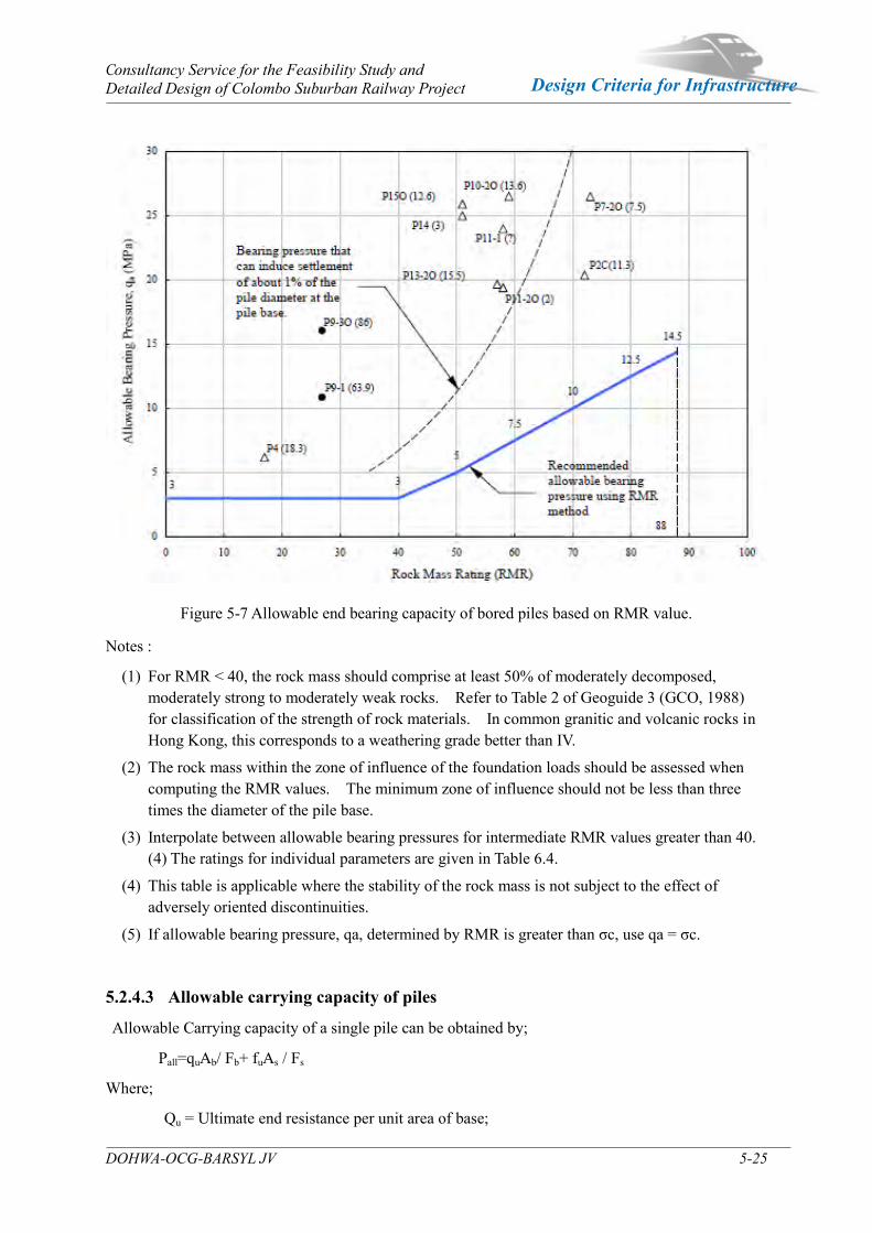
Consultancy Service for the Feasibility Study and Detailed Design of Colombo Suburban Railway Project
DOHWA-OCG-BARSYL JV 5-25
Design Criteria for Infrastructure
Figure 5-7 Allowable end bearing capacity of bored piles based on RMR value. Notes :
(1) For RMR < 40, the rock mass should comprise at least 50% of moderately decomposed, moderately strong to moderately weak rocks. Refer to Table 2 of Geoguide 3 (GCO, 1988) for classification of the strength of rock materials. In common granitic and volcanic rocks in Hong Kong, this corresponds to a weathering grade better than IV.
(2) The rock mass within the zone of influence of the foundation loads should be assessed when computing the RMR values. The minimum zone of influence should not be less than three times the diameter of the pile base.
(3) Interpolate between allowable bearing pressures for intermediate RMR values greater than 40. (4) The ratings for individual parameters are given in Table 6.4.
(4) This table is applicable where the stability of the rock mass is not subject to the effect of adversely oriented discontinuities.
(5) If allowable bearing pressure, qa, determined by RMR is greater than σc, use qa = σc.
5.2.4.3 Allowable carrying capacity of piles
Allowable Carrying capacity of a single pile can be obtained by;
Pall=quAb/ Fb+ fuAs / Fs
Where;
Qu = Ultimate end resistance per unit area of base;
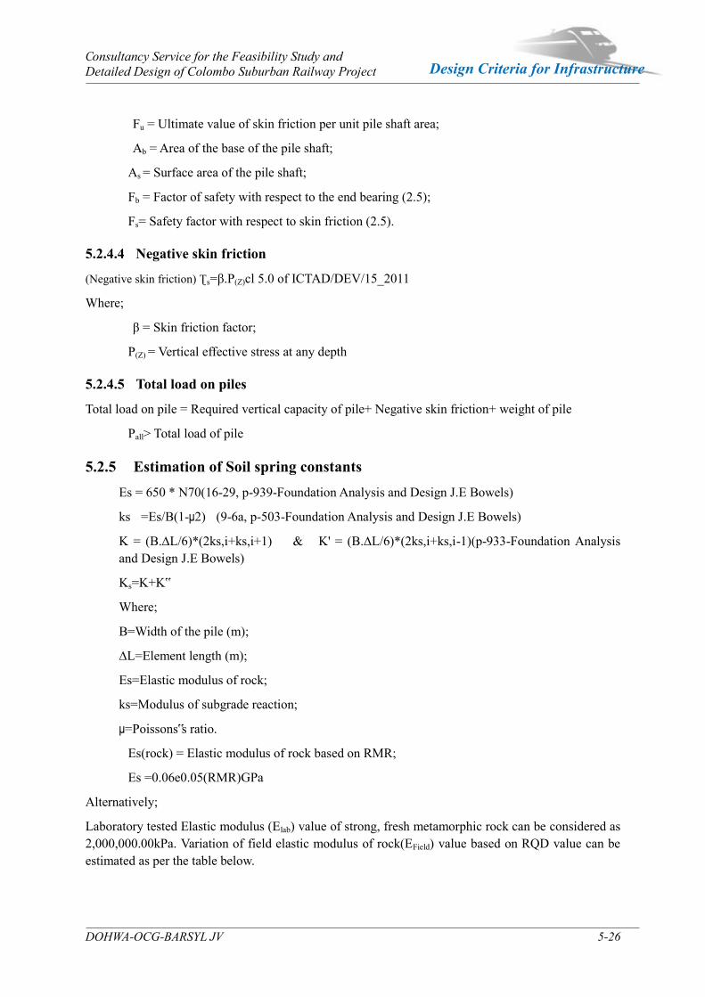
Consultancy Service for the Feasibility Study and Detailed Design of Colombo Suburban Railway Project
DOHWA-OCG-BARSYL JV 5-26
Design Criteria for Infrastructure
Fu = Ultimate value of skin friction per unit pile shaft area;
Ab = Area of the base of the pile shaft;
As = Surface area of the pile shaft;
Fb = Factor of safety with respect to the end bearing (2.5);
Fs= Safety factor with respect to skin friction (2.5).
5.2.4.4 Negative skin friction
(Negative skin friction) Ʈs=β.P(Z)cl 5.0 of ICTAD/DEV/15_2011
Where;
β = Skin friction factor;
P(Z) = Vertical effective stress at any depth
5.2.4.5 Total load on piles
Total load on pile = Required vertical capacity of pile+ Negative skin friction+ weight of pile
Pall> Total load of pile 5.2.5 Estimation of Soil spring constants
Es = 650 * N70(16-29, p-939-Foundation Analysis and Design J.E Bowels)
ks =Es/B(1-μ2) (9-6a, p-503-Foundation Analysis and Design J.E Bowels)
K = (B.∆L/6)*(2ks,i+ks,i+1) & K' = (B.∆L/6)*(2ks,i+ks,i-1)(p-933-Foundation Analysis and Design J.E Bowels)
Ks=K+K‟
Where;
B=Width of the pile (m);
∆L=Element length (m);
Es=Elastic modulus of rock;
ks=Modulus of subgrade reaction;
μ=Poissons‟s ratio.
Es(rock) = Elastic modulus of rock based on RMR;
Es =0.06e0.05(RMR)GPa
Alternatively;
Laboratory tested Elastic modulus (Elab) value of strong, fresh metamorphic rock can be considered as 2,000,000.00kPa. Variation of field elastic modulus of rock(EField) value based on RQD value can be estimated as per the table below.
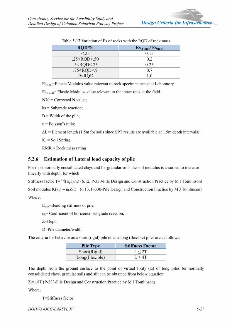
Consultancy Service for the Feasibility Study and Detailed Design of Colombo Suburban Railway Project
DOHWA-OCG-BARSYL JV 5-27
Design Criteria for Infrastructure
Table 5-17 Variation of Es of rocks with the RQD of rock mass RQD/% Es(Field)/ Es(lab)
<.25 0.15 .25<RQD<.50 0.2 .5<RQD<.75 0.25 .75<RQD<.9 0.7
.9<RQD 1.0
Es(Lab)=Elastic Modulus value relevant to rock specimen tested at Laboratory
Es(Field)= Elastic Modulus value relevant to the intact rock at the field.
N70 = Corrected N value;
ks = Subgrade reaction;
B = Width of the pile;
υ = Poisson‟s ratio;
∆L = Element length (1.5m for soils since SPT results are available at 1.5m depth intervals);
Ks = Soil Spring;
RMR = Rock mass rating 5.2.6 Estimation of Lateral load capacity of pile For most normally consolidated clays and for granular soils the soil modulus is assumed to increase linearly with depth, for which
Stiffness factor T= 5√(EpIp/nh) (6.12, P-330-Pile Design and Construction Practice by M J Tomlinson)
Soil modulus K(kh) = nhZ/D (6.13, P-330-Pile Design and Construction Practice by M J Tomlinson)
Where;
EpIp=Bending stiffness of pile;
nh= Coefficient of horizontal subgrade reaction;
Z=Dept;
D=Pile diameter/width.
The criteria for behavior as a short (rigid) pile or as a long (flexible) piles are as follows:
Pile Type Stiffness Factor Short(Rigid) L ≤ 2T
Long(Flexible) L ≥ 4T
The depth from the ground surface to the point of virtual fixity (zf) of long piles for normally consolidated clays, granular soils and silt can be obtained from below equation.
Zf=1.8T (P-333-Pile Design and Construction Practice by M J Tomlinson)
Where;
T=Stiffness factor

Consultancy Service for the Feasibility Study and Detailed Design of Colombo Suburban Railway Project
DOHWA-OCG-BARSYL JV 5-28
Design Criteria for Infrastructure
For Short piles;
Figure 5-8 Brinch Hansen‟s method for calculating ultimate lateral resistance of short piles (a) Soil Reactions (b) Shearing force diagram (c) Bending moment diagram.
The point of rotation at depth x is correctly chosen whenΣM=0, where M is the moment at the depth of z=X as per the given equation below
(P-3323- Pile Design and Construction Practice by M J Tomlinson)
Where; pz is the unit passive resistance of an element at a depth z below theground surface is then given bypz= pozKqz+cKcz
Where;poz is the effective overburden pressure at depth z, c is the cohesion of the soil at depth z, and Kqz and Kcz are the passive pressure coefficients for the frictional and cohesive components respectively at depth z.
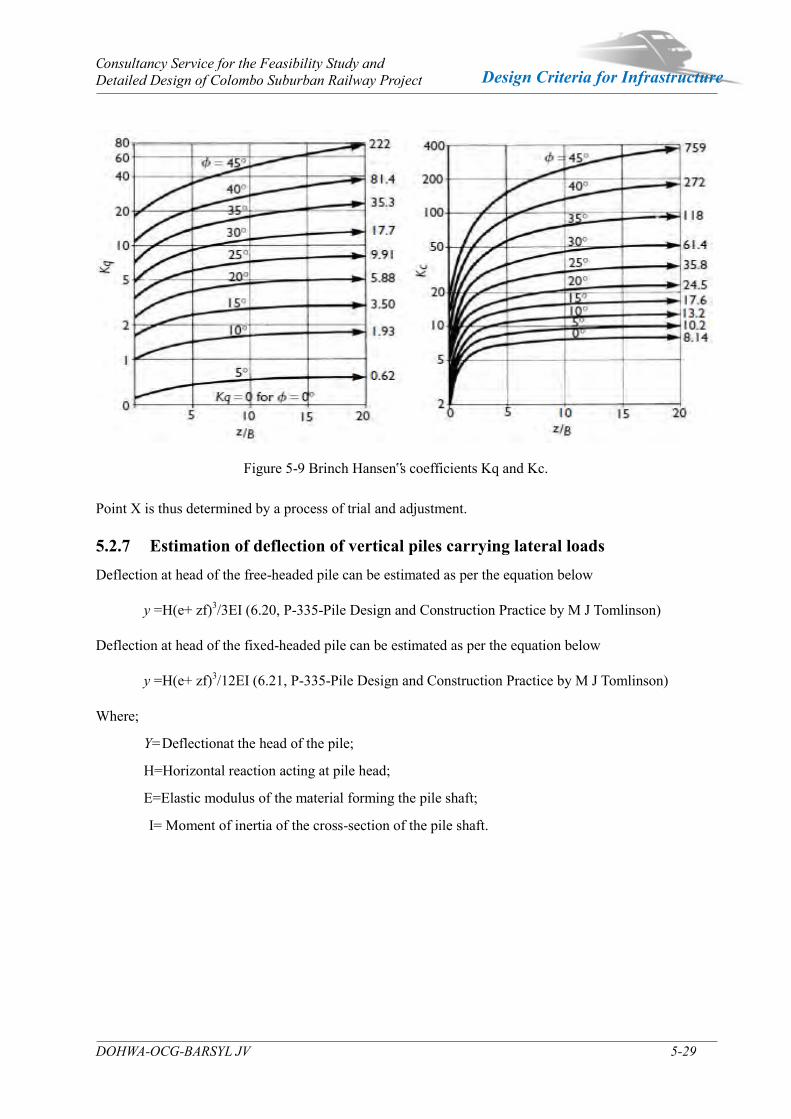
Consultancy Service for the Feasibility Study and Detailed Design of Colombo Suburban Railway Project
DOHWA-OCG-BARSYL JV 5-29
Design Criteria for Infrastructure
Figure 5-9 Brinch Hansen‟s coefficients Kq and Kc. Point X is thus determined by a process of trial and adjustment. 5.2.7 Estimation of deflection of vertical piles carrying lateral loads Deflection at head of the free-headed pile can be estimated as per the equation below
y =H(e+ zf)3/3EI (6.20, P-335-Pile Design and Construction Practice by M J Tomlinson)
Deflection at head of the fixed-headed pile can be estimated as per the equation below
y =H(e+ zf)3/12EI (6.21, P-335-Pile Design and Construction Practice by M J Tomlinson)
Where;
Y=Deflectionat the head of the pile;
H=Horizontal reaction acting at pile head;
E=Elastic modulus of the material forming the pile shaft;
I= Moment of inertia of the cross-section of the pile shaft.
Consultancy Service for the Feasibility Study and Detailed Design of Colombo Suburban Railway Project
DOHWA-OCG-BARSYL JV 5-30
Design Criteria for Infrastructure
5.2.8 Estimation of settlement of single piles at the working load for piles socketed in to the rocks
Settlement of single pile at working load can be estimated as per the equation below.
ρ=QIp/BEd(4.49, P-212-Pile Design and Construction Practice by M J Tomlinson)
Where;
ρ=Settlement;
Q=Applied axial load;
Ed=Elastic modulus of bearing stratum;
Ip=IoRkRhRv for floating piles and Ip=IoRkRbRv for end bearing piles;
I0 - Settlement influence factor for incompressible pile in semi-infinite mass, for ν = 0.5;
Rk= Correction factor for pile compressibility;
Rh= Correction factor for finite depth of layer on a rigid base;
Rb = Correction factor for stiffness of bearing stratum;
Rv = correction factor for poisson‟s ratio;
B= Diameter of the pile;
K= pile stiffness factor (EpRA/Es); RA = 1 for a soli
Consultancy Service for the Feasibility Study and Detailed Design of Colombo Suburban Railway Project
DOHWA-OCG-BARSYL JV 5-31
Design Criteria for Infrastructure
5.3 Bridges and Other Structures
5.3.1 Introduction The purpose of this chapter is to present the Design Criteria for viaducts, over bridges, retaining walls and culverts for the proposed Colombo Suburban Railway project.
This chapter shall be applied for the structural design for the permanent structures such as viaducts, overpass/underpass-bridges, retaining walls and culverts related, including all components of the structures such as abutments, foundations, piers, pier caps, decks, etc.
These document summaries the design criteria for the following aspects concerning bridges and viaducts:
Material characteristics;
Actions and load combinations;
Specific railway requirements;
5.3.1.1 Acronyms
Table 5-18 Definition of Acronyms Acronyms Definition
BS British Standard BS EN NA British National Annexe to BS EN
SLS NA Sri Lanka Standard, Sri Lanka National Annexe to Eurocode
UIC International Union of Railways Codes & leaflets
5.3.1.2 Definitions of structures
Underbridge : An underbridge is defined as a bridging structure that supports the infrastructure.
Viaduct : A viaduct is a multi-span underbridge.
Overbridge : An over bridge is defined as a structure carrying rail or vehicular traffic and/or nonmotorised users over tracks, including at bifurcations, junctions and spurs. Over bridges include railway bridges, highway bridges, accommodation bridges and foot, cycle way and bridleway bridges.
Underpass : An underpass is an under bridge whose main purpose is to allow the crossing of a Public right of way, the access or accommodation access and has typically a proportion of the embankment, rather than a bridge deck, between its uppermost point and the road or rail above.
Culvert : A culvert is an under bridge whose main purpose is to allow the crossing of a watercourse. Span is greater than 0.9 m and has typically a proportion of the embankment, rather than a bridge deck, between its uppermost point and the road or rail above.
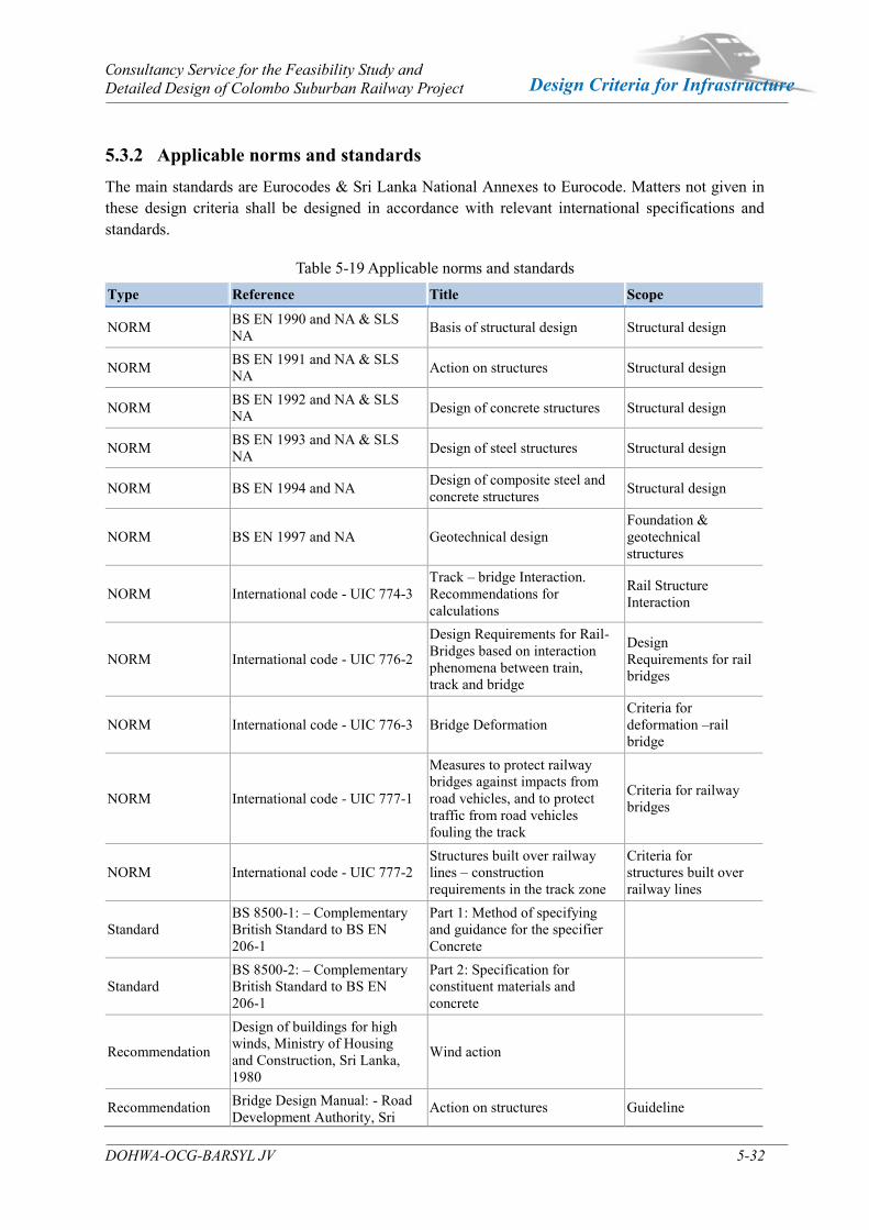
Consultancy Service for the Feasibility Study and Detailed Design of Colombo Suburban Railway Project
DOHWA-OCG-BARSYL JV 5-32
Design Criteria for Infrastructure
5.3.2 Applicable norms and standards The main standards are Eurocodes & Sri Lanka National Annexes to Eurocode. Matters not given in these design criteria shall be designed in accordance with relevant international specifications and standards.
Table 5-19 Applicable norms and standards Type Reference Title Scope
NORM BS EN 1990 and NA & SLS NA Basis of structural design Structural design
NORM BS EN 1991 and NA & SLS NA Action on structures Structural design
NORM BS EN 1992 and NA & SLS NA Design of concrete structures Structural design
NORM BS EN 1993 and NA & SLS NA Design of steel structures Structural design
NORM BS EN 1994 and NA Design of composite steel and concrete structures Structural design
NORM BS EN 1997 and NA Geotechnical design Foundation & geotechnical structures
NORM International code - UIC 774-3 Track – bridge Interaction. Recommendations for calculations
Rail Structure Interaction
NORM International code - UIC 776-2
Design Requirements for Rail-Bridges based on interaction phenomena between train, track and bridge
Design Requirements for rail bridges
NORM International code - UIC 776-3 Bridge Deformation Criteria for deformation –rail bridge
NORM International code - UIC 777-1
Measures to protect railway bridges against impacts from road vehicles, and to protect traffic from road vehicles fouling the track
Criteria for railway bridges
NORM International code - UIC 777-2 Structures built over railway lines – construction requirements in the track zone
Criteria for structures built over railway lines
Standard BS 8500-1: – Complementary British Standard to BS EN 206-1
Part 1: Method of specifying and guidance for the specifier Concrete
Standard BS 8500-2: – Complementary British Standard to BS EN 206-1
Part 2: Specification for constituent materials and concrete
Recommendation
Design of buildings for high winds, Ministry of Housing and Construction, Sri Lanka, 1980
Wind action
Recommendation Bridge Design Manual: - Road Development Authority, Sri
Action on structures Guideline

Consultancy Service for the Feasibility Study and Detailed Design of Colombo Suburban Railway Project
DOHWA-OCG-BARSYL JV 5-33
Design Criteria for Infrastructure
Type Reference Title Scope Lanka, 1997
Recommendation Standard method of detailing structural concrete-Institute of Structural Engineers, 2006
Standard Method of Detailing Structural Concrete Guideline
Recommendation KR code 2012 Korea rail network authority Guideline
Recommendation AASHTO LRFD American association of State Highway and Transportation Officials
Guideline
Recommendation ACI American Concrete Institution Guideline Recommendation IRS code India Railway Specifications Guideline Recommendation CIRIA C543, 2001 Bridge detailing guide Guideline
Recommendation CIRIA C660, 2007 Early-age thermal crack control in concrete
Guideline on crack control
Note: above list is not exhaustive. 5.3.3 Units and Sign convention
Units
The design basis is developed adopting the international system (IS):
- Distance, displacement : m; mm - Force : kN; MN - Bending Moment : kN.m; MN.m - Stresses : MPa - Unit weight : kN/m3
Sign convention
Technical document provided observe the following sign convention:
- X – Longitudinal axis along the bridge - Y – Transverse axis - Z – Vertical axis – oriented in gravitational direction. Note: These conventions should be applied unless otherwise specified.
5.3.4 Design Life The indicative design lives for components of structures are introduced in Table 2.1 of SLS EN 1990.
However, the minimum design life of 100 years such as bridges and stations shall be considered for the permanent parts of structures in this project. Regular inspection and maintenance is required to ensure that the design lives are achieved. Some elements will require replacement during the design life of the bridge. The minimum design lives of the main structural components are given in the following table:

Consultancy Service for the Feasibility Study and Detailed Design of Colombo Suburban Railway Project
DOHWA-OCG-BARSYL JV 5-34
Design Criteria for Infrastructure
Table 5-20 Minimum Design life of Structural Components
Element Minimum Design Life (Years) Remark
Temporary Structures a 10
Bearings 30 20 years for minor components only
Expansion Joint 20 10 years for minor components only
Parapet (Metal parts only) 50
Parapet (Concrete parts only) 100
Drainage system 20
Building structures and other common structures, not listed elsewhere in this table 50
Railway bridges, Stations (Foundations, Piers, Deck, etc.) 100
Durability – Design working life 100 Intended working life a Structures or parts of structures than can be dismantled with a view of bearing re-used should not be considered as temporary.
5.3.5 Materials
5.3.5.1 Concrete
According to Table 3.1 of BS EN 1992-1-1, the table gives the minimal characteristic compressive strengths for different types of concrete.
Table 5-21 Strength and deformation characteristics for concrete fck fck cube fcm fctm fctk,0,05 fctk,0,95 Ecm εc1 ε cu1 ε c2 ε cu2 n ε c3 ε cu3
(MPa) (MPa) (MPa) (MPa) (MPa) (MPa) (GPa ) (‰) (‰) (‰) (‰) (‰) (‰)
30 37 38 2,9 2.0 3.8 33 2,2 3,5 2 3,5 2 1,75 3,5
35 45 43 3.2 2.2 4.2 34 2,25 3,5 2 3,5 2 1,75 3,5
40 50 48 3.5 2.5 4.6 35 2,3 3,5 2 3,5 2 1,75 3,5
45 55 53 3.8 2.7 4.9 36 2.4 3.5 2 3.5 2 1.75 3.5
50 60 58 4.1 2.9 5.3 37 2.45 3.5 2 3.5 2 1.75 3.5 Poisson‟s ratio, ν of concrete may be taken equal to 0,2 for uncracked concrete and 0 for cracked concrete according to clause 3.1.3 (4) of BS EN1992-1-1.
Unless more accurate information is available, the linear coefficient of thermal expansion may be
taken equal to 10 ㆍ 10-6 K-1 according to 3.1.3 (5) of BS EN1992-1-1.
5.3.5.2 Applicable Concrete and reinforced bars for each component
Minimum concrete strength and reinforced bar requirements for each component of structure are as following table. The table below is a proposal of concrete strength to be taken into account for each element.

Consultancy Service for the Feasibility Study and Detailed Design of Colombo Suburban Railway Project
DOHWA-OCG-BARSYL JV 5-35
Design Criteria for Infrastructure
Table 5-22 Concrete design criteria strength and Reinforced Bars for each component
Classification Application Point Concrete - Design criteria strength
( : MPa) Reinforced bar
(MPa) 16/20 20/25 25/30 30/37 35/45 40/50 250 350 460 500
Bridge
Super-structures
PSC Girder
● ●
RC slab
●
●
Rigid frame
●
●
Sub-structures
Abutment
●
●
Pier
●
●
bottom (lean) ●
Culvert Slab & Wall ● ●
Retaining wall Slab & Wall ● ● Drainage structure Clear span B≤1.2m ● ●
5.3.5.3 Durability
The durability focuses on the durability requirements for concrete elements, the main construction material, it addresses some specific issues regarding cast-in items and includes the durability approach for the design of structural steel elements
Concrete cover : 100 years design working life
Cracking control : Serviceability limit - time to corrosion initiation
(1) Determination of Cover depth to conventional(bar) reinforcement
The cover to reinforcement considering the approach of BS EN 1992-1-1 and its UK National Annex (NA BS EN 1992-1-1), in particular the use of „additive safety element‟ (Δcdur,γ).
In accordance with Clause 4.4 of BS EN1992-1-1, the concrete cover value cnom for durability has been calculated as:
cnom = cmin + Δcdev (1)
Where the minimum cover value cmin is: cmin = max (cmin,b; cdur; 10 mm) (2)
with cdur={cmin,dur + Δcdur,γ – Δcdur,st – Δcdur,add}; Where: cmin,b is the minimum cover depths for transfer of bond stresses from reinforcing bars. The
minimum should be checked to ensure that it is at least equal to the reinforcing bar diameter.
cdur is the sum of all durability covers cmin,dur, Δcdur,γ, Δcdur,st and Δcdur,add
cmin,dur is the minimum cover due to environmental conditions, (i.e. representing the minimum cover depths for durability) are minimum values for reinforced (R) or prestressed (P) elements that are taken from Table A.5 in Annex A of BS 8500-1 for an „intended working life of at least 100 years‟.
Δcdur,γ are mandatory minimum values representing the „additive safety element‟. These values are only applicable to Consequence Class 3 (CC3) elements, i.e. to elements forming part of the
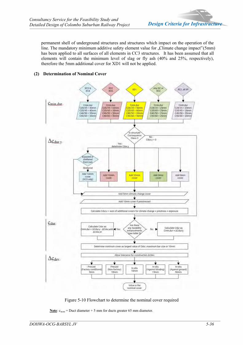
Consultancy Service for the Feasibility Study and Detailed Design of Colombo Suburban Railway Project
DOHWA-OCG-BARSYL JV 5-36
Design Criteria for Infrastructure
permanent shell of underground structures and structures which impact on the operation of the line. The mandatory minimum additive safety element value for „Climate change impact‟ (5mm) has been applied to all surfaces of all elements in CC3 structures. It has been assumed that all elements will contain the minimum level of slag or fly ash (40% and 25%, respectively), therefore the 5mm additional cover for XD1 will not be applied.
(2) Determination of Nominal Cover
Figure 5-10 Flowchart to determine the nominal cover required Note: cnom = Duct diameter + 5 mm for ducts greater 65 mm diameter.
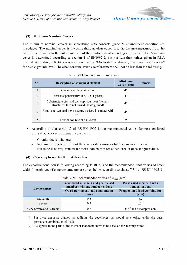
Consultancy Service for the Feasibility Study and Detailed Design of Colombo Suburban Railway Project
DOHWA-OCG-BARSYL JV 5-37
Design Criteria for Infrastructure
(3) Minimum Nominal Covers
The minimum nominal covers in accordance with concrete grade & environment condition are introduced. The nominal cover is the same thing as clear cover. It is the distance measured from the face of the member to the outermost face of the reinforcement including stirrups or links. Minimum cover is determined according to section 4 of EN1992-2, but not less than values given in RDA manual. According to RDA, service environment is “Moderate” for above ground level, and “Severe” for below ground level. The clear concrete over to reinforcement shall not be less than the following.
Table 5-23 Concrete minimum cover
No. Description of structural element Minimum Cover (mm) Remark
1 Cast-in situ Superstructure 45
2 Precast superstructure (i.e. PSC I girder) 40
3 Substructure pier and pier cap, abutment (i.e. any structure‟s face not buried inside ground) 45
4 Abutment stem and box structure surface in contact with earth 45
5 Foundation pile and pile cap 75
According to clause 4.4.1.2 of BS EN 1992-1, the recommended values for post-tensioned ducts about concrete minimum cover are :
- Circular ducts : diameter - Rectangular ducts : greater of the smaller dimension or half the greater dimension - But there is no requirement for more than 80 mm for either circular or rectangular ducts.
(4) Cracking in service limit state (SLS)
The exposure condition is following according to RDA, and the recommended limit values of crack width for each type of concrete structure are given below according to clause 7.3.1 of BS EN 1992-2
Table 5-24 Recommended values of wmax (mm)
Environment
Reinforced members and prestressed members without bonded tendons
Prestressed members with bonded tendons
Quasi-permanent load combination (mm)
Frequent and load combination (mm)
Moderate 0.3 0.2 Severe 0.3 0.21)
Very Severe and Extreme 0.3 0.22) and decompression
1) For these exposure classes, in addition, the decompression should be checked under the quasi-permanent combination of loads
2) 0.2 applies to the parts of the member that do not have to be checked for decompression
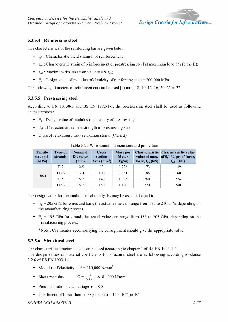
Consultancy Service for the Feasibility Study and Detailed Design of Colombo Suburban Railway Project
DOHWA-OCG-BARSYL JV 5-38
Design Criteria for Infrastructure
5.3.5.4 Reinforcing steel
The characteristics of the reinforcing bar are given below :
fyk : Characteristic yield strength of reinforcement
εuk : Characteristic strain of reinforcement or prestressing steel at maximum load 5% (class B);
εud : Maximum design strain value = 0.9 εuk;
Es : Design value of modulus of elasticity of reinforcing steel = 200,000 MPa.
The following diameters of reinforcement can be used [in mm] : 8, 10, 12, 16, 20, 25 & 32
5.3.5.5 Prestressing steel
According to EN 10138-3 and BS EN 1992-1-1, the prestressing steel shall be used as following characteristics :
Ep : Design value of modulus of elasticity of prestressing
Fpk : Characteristic tensile strength of prestressing steel
Class of relaxation : Low relaxation strand (Class 2)
Table 5-25 Wire strand – dimensions and properties Tensile
strength (MPa)
Type of strands
Nominal Diameter
(mm)
Cross section
Area (mm2)
Mass per Meter (kg/m)
Characteristic value of max. force, fpk (kN)
Characteristic value of 0,1 % proof force,
fp0,1 (kN)
1860
T12 12.5 93 0.726 173 149 T12S 13.0 100 0.781 186 160 T15 15.2 140 1.095 260 224
T15S 15.7 150 1.170 279 240 The design value for the modulus of elasticity, Ep may be assumed equal to:
Ep = 205 GPa for wires and bars, the actual value can range from 195 to 210 GPa, depending on the manufacturing process.
Ep = 195 GPa for strand, the actual value can range from 185 to 205 GPa, depending on the manufacturing process.
*Note : Certificates accompanying the consignment should give the appropriate value.
5.3.5.6 Structural steel
The characteristic structural steel can be used according to chapter 3 of BS EN 1993-1-1. The design values of material coefficients for structural steel are as following according to clause 3.2.6 of BS EN 1993-1-1.
Modulus of elasticity E = 210,000 N/mm2
Shear modulus G = 𝐸
2(1+𝜈) ≈ 81,000 N/mm2
Poisson‟s ratio in elastic stage 𝜈 = 0,3
Coefficient of linear thermal expansion α = 12 × 10-6 per K-1
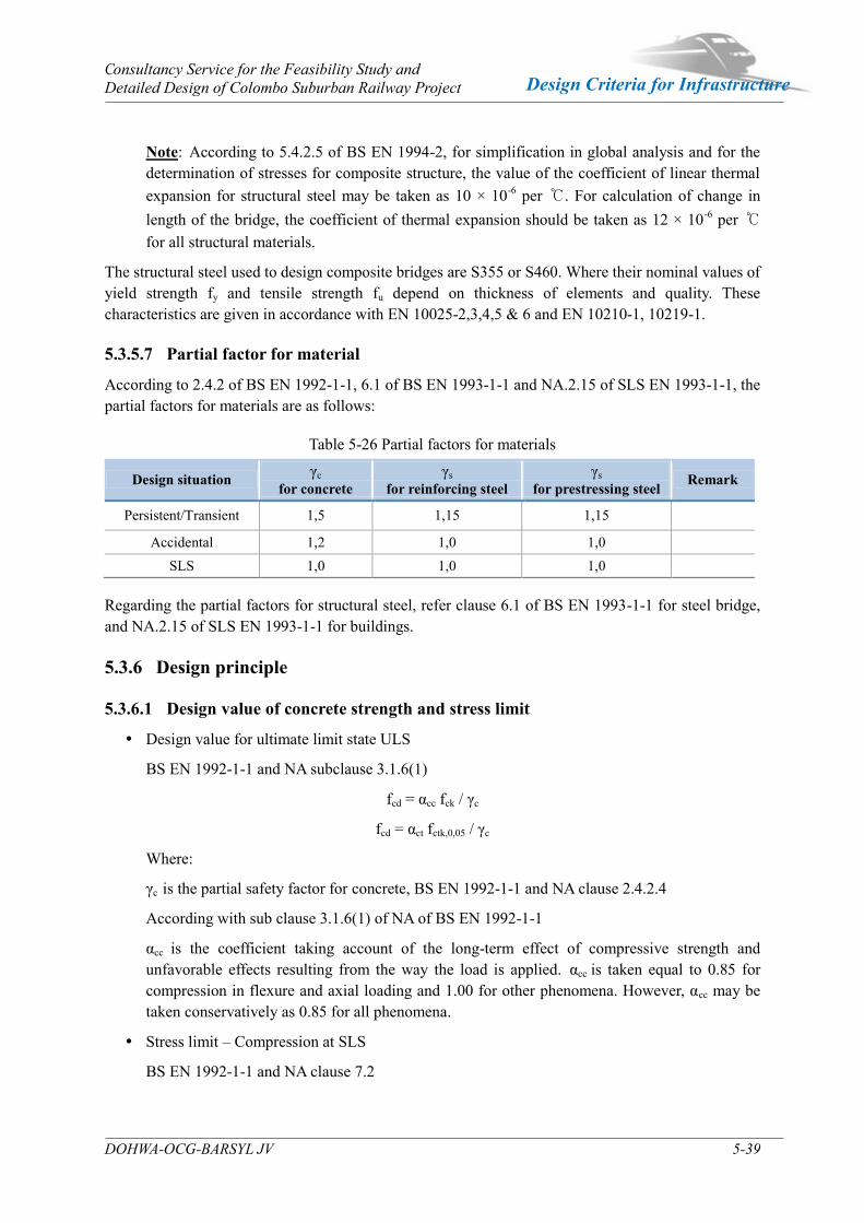
Consultancy Service for the Feasibility Study and Detailed Design of Colombo Suburban Railway Project
DOHWA-OCG-BARSYL JV 5-39
Design Criteria for Infrastructure
Note: According to 5.4.2.5 of BS EN 1994-2, for simplification in global analysis and for the determination of stresses for composite structure, the value of the coefficient of linear thermal expansion for structural steel may be taken as 10 × 10-6 per ℃. For calculation of change in length of the bridge, the coefficient of thermal expansion should be taken as 12 × 10-6 per ℃ for all structural materials.
The structural steel used to design composite bridges are S355 or S460. Where their nominal values of yield strength fy and tensile strength fu depend on thickness of elements and quality. These characteristics are given in accordance with EN 10025-2,3,4,5 & 6 and EN 10210-1, 10219-1.
5.3.5.7 Partial factor for material
According to 2.4.2 of BS EN 1992-1-1, 6.1 of BS EN 1993-1-1 and NA.2.15 of SLS EN 1993-1-1, the partial factors for materials are as follows:
Table 5-26 Partial factors for materials
Design situation γc for concrete
γs for reinforcing steel
γs for prestressing steel Remark
Persistent/Transient 1,5 1,15 1,15
Accidental 1,2 1,0 1,0 SLS 1,0 1,0 1,0
Regarding the partial factors for structural steel, refer clause 6.1 of BS EN 1993-1-1 for steel bridge, and NA.2.15 of SLS EN 1993-1-1 for buildings. 5.3.6 Design principle
5.3.6.1 Design value of concrete strength and stress limit
Design value for ultimate limit state ULS
BS EN 1992-1-1 and NA subclause 3.1.6(1)
fcd = αcc fck / γc
fcd = αct fctk,0,05 / γc
Where:
γc is the partial safety factor for concrete, BS EN 1992-1-1 and NA clause 2.4.2.4
According with sub clause 3.1.6(1) of NA of BS EN 1992-1-1
αcc is the coefficient taking account of the long-term effect of compressive strength and unfavorable effects resulting from the way the load is applied. αcc is taken equal to 0.85 for compression in flexure and axial loading and 1.00 for other phenomena. However, αcc may be taken conservatively as 0.85 for all phenomena.
Stress limit – Compression at SLS
BS EN 1992-1-1 and NA clause 7.2

Consultancy Service for the Feasibility Study and Detailed Design of Colombo Suburban Railway Project
DOHWA-OCG-BARSYL JV 5-40
Design Criteria for Infrastructure
Table 5-27 Stress limit for compression component at SLS State Stresses limit
Service limit state Characteristic σc ≤ 0,60 fck Service limit state Quasi-Permanent σc ≤ 0,45 fck
Where:
σc is Concrete compressive stresses
Note: It may be required to specify the concrete compressive strength, fck(t) in lieu of fck, at time t for a number of stages (e.g. remolding, transfer of pre-stress), where:
fck(t) = fcm(t) - 8 (MPa) for 3 < t < 28 days or fck(t) = fck for t ≥ 28 days
Stress limit – Tension at SLS
BS EN 1992-2 and NA clause 7.3
a. For reinforced concrete components:
For SLS frequent, we check the crack width according to §9.2.5.5 in this report;
b. For prestressed concrete component
- Precast segmental component using post tensioning system:
For SLS characteristics, no tensile stress is permitted at joints;
For SLS frequent, no tensile stress is permitted at joints;
For SLS quasi-permanent, no tensile stress is permitted at joints.
- Precast and cast in situ concrete components with bonded tendons:
For SLS quasi-permanent, no tensile stress is permitted in component with the following description class: XC2, XC3 and XC4;
For SLS frequent, no tensile stress is permitted in component with the following description class: XD1, XD2, XD3, XS1, XS2 and XS3.
- Precast and cast in situ concrete components without bonded tendons:
The decompression is allowed, only crack checking is required under SLS quasi-permanent.
Consultancy Service for the Feasibility Study and Detailed Design of Colombo Suburban Railway Project
DOHWA-OCG-BARSYL JV 5-41
Design Criteria for Infrastructure
5.3.6.2 Design yield strength and stress limit of reinforcing steel
Design yield strength at ultimate limit service ULS
fyd = fyk/γs
Where:
γs : partial factor for reinforcing steel, BS EN 1992-1-1 subclause 2.4.2.4 (1)
Tensile stress limit at service limit state SLS
BS EN 1992-1-1 subclause 7.2 (5)
Table 5-28 Stress limit for tensile component at SLS State Reinforcing steel
Service limit state characteristic σst ≤ 0.80 fyk Service limit state frequent or quasi-permanent (see § 6.1.2) w ≤ wmax
Where:
σst: Tensile stress in reinforced steel
w: Crack width
All main and transverse reinforcement to be 460MPa and for shear links both 250MPa round steel bars and 460Mpa Tore steel bars to be used.
Note 1: under characteristic service limit state, the value of stress in the reinforcement will be limited to 300 MPa to use the simplified method of control cracking.
Note 2: a fatigue verification is generally not necessary for the following structures and structural elements:
- Footbridges, except for structural components very sensitive to wind action;
- Buried arch and frame structures with a minimum earth cover of 1.00m and 1.500m respectively for road and railway bridges;
- Foundations;
- Piers and columns which are not rigidly connected to superstructures;
- Retaining walls for roads and railways;
- Abutments of road and railway bridges which are not rigidly connected to superstructures, except the slabs of hollow abutments;
- Prestressing and reinforcing steel, in regions where, under the frequent combination of action and Pk, only compressive stresses occur at the extreme concrete fibers.
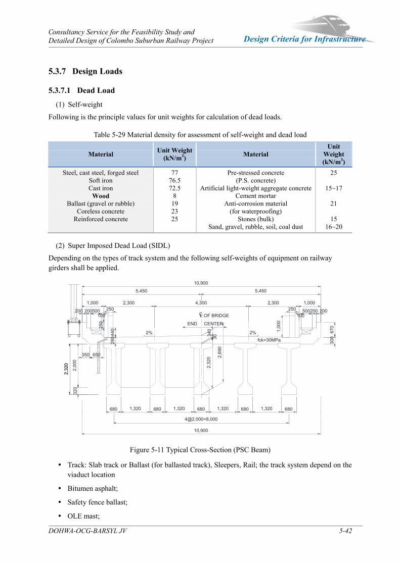
Consultancy Service for the Feasibility Study and Detailed Design of Colombo Suburban Railway Project
DOHWA-OCG-BARSYL JV 5-42
Design Criteria for Infrastructure
5.3.7 Design Loads
5.3.7.1 Dead Load
(1) Self-weight
Following is the principle values for unit weights for calculation of dead loads.
Table 5-29 Material density for assessment of self-weight and dead load
Material Unit Weight (kN/m3) Material
Unit Weight (kN/m3)
Steel, cast steel, forged steel Soft iron Cast iron
Wood Ballast (gravel or rubble)
Coreless concrete Reinforced concrete
77 76.5 72.5
8 19 23 25
Pre-stressed concrete (P.S. concrete)
Artificial light-weight aggregate concrete Cement mortar
Anti-corrosion material (for waterproofing)
Stones (bulk) Sand, gravel, rubble, soil, coal dust
25
15~17
21
15 16~20
(2) Super Imposed Dead Load (SIDL)
Depending on the types of track system and the following self-weights of equipment on railway girders shall be applied.
Figure 5-11 Typical Cross-Section (PSC Beam)
Track: Slab track or Ballast (for ballasted track), Sleepers, Rail; the track system depend on the viaduct location
Bitumen asphalt;
Safety fence ballast;
OLE mast;
1,00
0
250 250100
2,32
0
200500
670
680
2,32
0
1,320
300
2,32
0
4@2,000=8,000
200
2,69
0
1,320
10,900
680
320
680
280
5,450
100
350
10,900
5,450
200
1,320
440
1,000
650
680
30
680
340
2,00
0
1,320
250
fck=30MPa2%2%
500200
2,300 4,300 2,300 1,000
L OF BRIDGE
CENTEREND
C
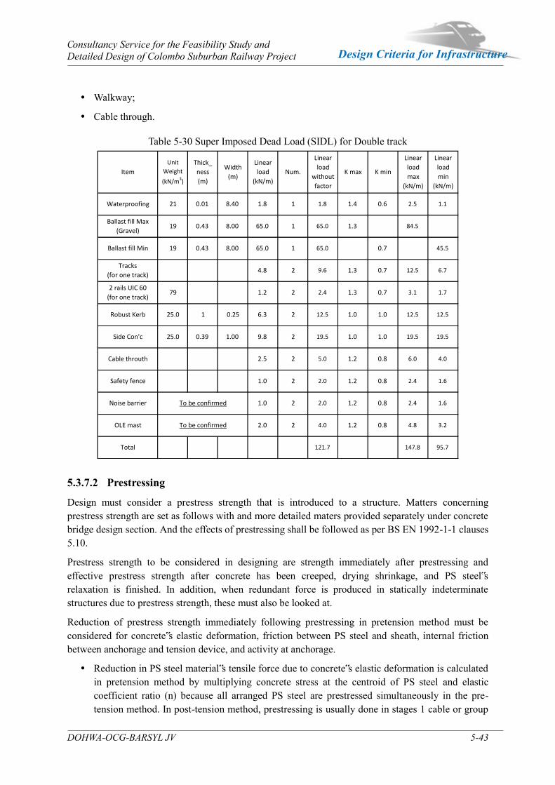
Consultancy Service for the Feasibility Study and Detailed Design of Colombo Suburban Railway Project
DOHWA-OCG-BARSYL JV 5-43
Design Criteria for Infrastructure
Walkway;
Cable through.
Table 5-30 Super Imposed Dead Load (SIDL) for Double track
5.3.7.2 Prestressing
Design must consider a prestress strength that is introduced to a structure. Matters concerning prestress strength are set as follows with and more detailed maters provided separately under concrete bridge design section. And the effects of prestressing shall be followed as per BS EN 1992-1-1 clauses 5.10.
Prestress strength to be considered in designing are strength immediately after prestressing and effective prestress strength after concrete has been creeped, drying shrinkage, and PS steel‟s relaxation is finished. In addition, when redundant force is produced in statically indeterminate structures due to prestress strength, these must also be looked at.
Reduction of prestress strength immediately following prestressing in pretension method must be considered for concrete‟s elastic deformation, friction between PS steel and sheath, internal friction between anchorage and tension device, and activity at anchorage.
Reduction in PS steel material‟s tensile force due to concrete‟s elastic deformation is calculated in pretension method by multiplying concrete stress at the centroid of PS steel and elastic coefficient ratio (n) because all arranged PS steel are prestressed simultaneously in the pre-tension method. In post-tension method, prestressing is usually done in stages 1 cable or group
Waterproofing 1.4 0.6 2.5 1.1
Linear
load
without
factor
K max K min
Linear
load
max
(kN/m)
Linear
load
min
(kN/m)
Item
Unit
Weight
(kN/m3)
Thick_
ness
(m)
Width
(m)
Linear
load
(kN/m)
Num.
8.40 1.8 1
65.0 1.3 84.5
65.0 0.7
Ballast fill Max
(Gravel)19 0.43 8.00 65.0 1
1.821 0.01
45.5Ballast fill Min 19 0.43 8.00 65.0 1
12.5 12.5
1.2 2 2.4 1.3 0.7
1.2 0.8 6.0 4.0
Robust Kerb 25.0 1 0.25 6.3 2 12.5 1.0 1.0
2.4 1.6Safety fence 1.0 2 2.0 1.2 0.8
Cable throuth 2.5
2 4.0 1.2 0.8 4.8 3.2OLE mast 2.0
1.2 0.8 2.4 1.6Noise barrier 1.0 2 2.0To be confirmed
To be confirmed
147.8 95.7Total 121.7
Tracks
(for one track)4.8 2 9.6 1.3 0.7 12.5 6.7
Side Con'c 25.0 0.39 1.00 9.8 2 19.5 1.0 1.0 19.5 19.5
3.1 1.72 rails UIC 60
(for one track)79
2 5.0

Consultancy Service for the Feasibility Study and Detailed Design of Colombo Suburban Railway Project
DOHWA-OCG-BARSYL JV 5-44
Design Criteria for Infrastructure
at a time and already anchored PS steel‟s tensile force at every tension stage is changed in successive order. Therefore, these must be considered in calculating reduction of tensile force.
Reduction of tensile force in PS steel from friction is mainly caused by friction loss of sheath and PS steel. Generally, the reduction can be divided into changes in PS steel and the effects of length for calculation.
Reduction of tensile force in PS steel due to anchorage activity varies for different PSC methods. Setting is insignificant and can be ignored in screw and button anchorages. In wedge anchorage, relatively large activities take place so that reduction of tensile force in PS steel from friction and the scope of effect should be studies in advance by assuming activities from past performances.
Effective prestress force is calculated by taking into consideration the following effects at immediately after prestressing force.
Concrete creep
Continuous loads considered in this case are prestress strength and dead load.
Shrinkage of concrete
Relaxation of PS steel
Redundant force due to effective prestress force can be computed by multiplying PS steel‟s effective coefficient for average tensile force throughout the member with redundant force immediately following prestressing. Redundant force produced immediately after prestress force is acted on changes according to PS steel‟s tensile force reductions resulting from concrete‟s creep, shrinkage, and relaxation.
5.3.7.3 Creep and Shrinkage
Aside from concrete members, concrete‟s creep and shrinkage effects shall be considered when concrete‟s main girder and deck plate are synthesized such as in steel composite girder bridges.
The average outside ambient humidity, RH, expressed a relative humidity percentage may be taken as 70% for normal exposure condition as per clause 2.2.8 of RDA.
The creep and shrinkage effects of concrete structures should be calculated according to clause 3.1.4 of BS EN 1992-1-1 considering the construction phase. However, if the compressive stress permanently exceeds 0.45 fck(t), the non-linearity of creep should be considered according with BS EN clause 5.10.2.2.
For composite steel and concrete structures, the creep and shrinkage effects are calculated in accordance with clause 3.1.4 of BS EN 1992-1-1, clause 5.4.2.2 of BS EN 1994-2 and sub-clause 7.4.1(6) of BS EN 1994-2.

Consultancy Service for the Feasibility Study and Detailed Design of Colombo Suburban Railway Project
DOHWA-OCG-BARSYL JV 5-45
Design Criteria for Infrastructure
5.3.7.4 Earth Pressure
Earth pressure on structures shall be considered where filling material is retained by abutments, culverts, wing walls or any other parts of the structure. The nominal vertical earth loads shall be calculated as an overburden pressure using soil parameters. Soil material with constant density, and uniformly distributed over the structural component shall be considered. The negative effect shall be considered where appropriate. And horizontal earth pressure is also considered. Limit values of Earth pressures calculate according to clause 9.5 and Annex C of BS EN 1997-1.
5.3.7.5 Loading due to Water Current, Floating debris and Log Impact
Refer to clause 2.2.5 of RDA bridge design manual, the following would be considered if necessary.
(1) Horizontal forces due to water current
Piers which are parallel to the direction of water current, the intensity of the pressure is;
P = 52 KV2
P = intensity of pressure (kg/m2)
K = a constant depending on the shape of the pier as below table.
V = velocity of water current (m/sec) at the point where the pressure is being calculated
Table 5-31 Values of K depending on section shape Shape of Pier K Remark
Square ended pier 1.5
Circular pier or semi circular cutwaters 0.66
Triangular cutwaters 0.5 to 0.9
Trestle type piers 1.25
(2) Horizontal forces due to Floating debris
Where debris is likely, allowance shall be made for the force exerted by a minimum depth of 1.2m debris. The length of the debris applied to any one pier shall be one half of the sum of the adjacent spans with a maximum of 22.0 m where the deck is not submerged. For debris the formula for water current shall be used the value of the constant K being 1.0.
(3) Horizontal forces due to Log impact
When there is a possibility for driftwood and other drifting items to collide with a bridge, collision force shall be calculated from following equation.
P = 0.1 W ㆍ v Where
P = Collision force (t)
W = Weight of drifting item (t) (2t is assumed)
v = Surface velocity of water (m/s) here debris
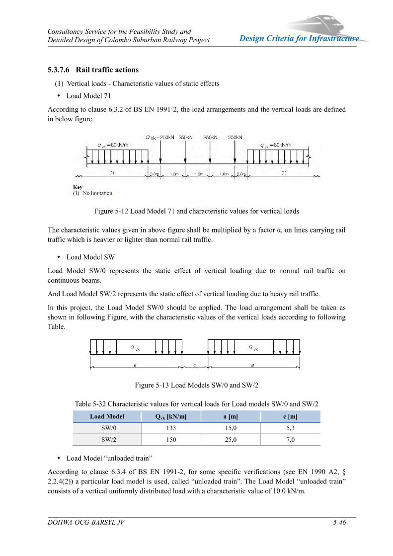
Consultancy Service for the Feasibility Study and Detailed Design of Colombo Suburban Railway Project
DOHWA-OCG-BARSYL JV 5-46
Design Criteria for Infrastructure
5.3.7.6 Rail traffic actions
(1) Vertical loads - Characteristic values of static effects
Load Model 71
According to clause 6.3.2 of BS EN 1991-2, the load arrangements and the vertical loads are defined in below figure.
Figure 5-12 Load Model 71 and characteristic values for vertical loads
The characteristic values given in above figure shall be multiplied by a factor α, on lines carrying rail traffic which is heavier or lighter than normal rail traffic.
Load Model SW
Load Model SW/0 represents the static effect of vertical loading due to normal rail traffic on continuous beams.
And Load Model SW/2 represents the static effect of vertical loading due to heavy rail traffic.
In this project, the Load Model SW/0 should be applied. The load arrangement shall be taken as shown in following Figure, with the characteristic values of the vertical loads according to following Table.
Figure 5-13 Load Models SW/0 and SW/2
Table 5-32 Characteristic values for vertical loads for Load models SW/0 and SW/2
Load Model Qvk [kN/m] a [m] c [m]
SW/0 133 15,0 5,3
SW/2 150 25,0 7,0
Load Model “unloaded train”
According to clause 6.3.4 of BS EN 1991-2, for some specific verifications (see EN 1990 A2, § 2.2.4(2)) a particular load model is used, called “unloaded train”. The Load Model “unloaded train” consists of a vertical uniformly distributed load with a characteristic value of 10.0 kN/m.
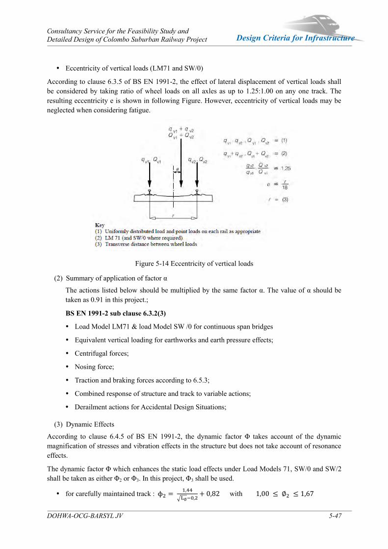
Consultancy Service for the Feasibility Study and Detailed Design of Colombo Suburban Railway Project
DOHWA-OCG-BARSYL JV 5-47
Design Criteria for Infrastructure
Eccentricity of vertical loads (LM71 and SW/0)
According to clause 6.3.5 of BS EN 1991-2, the effect of lateral displacement of vertical loads shall be considered by taking ratio of wheel loads on all axles as up to 1.25:1.00 on any one track. The resulting eccentricity e is shown in following Figure. However, eccentricity of vertical loads may be neglected when considering fatigue.
Figure 5-14 Eccentricity of vertical loads
(2) Summary of application of factor α
The actions listed below should be multiplied by the same factor α. The value of α should be taken as 0.91 in this project.;
BS EN 1991-2 sub clause 6.3.2(3)
Load Model LM71 & load Model SW /0 for continuous span bridges
Equivalent vertical loading for earthworks and earth pressure effects;
Centrifugal forces;
Nosing force;
Traction and braking forces according to 6.5.3;
Combined response of structure and track to variable actions;
Derailment actions for Accidental Design Situations;
(3) Dynamic Effects
According to clause 6.4.5 of BS EN 1991-2, the dynamic factor Φ takes account of the dynamic magnification of stresses and vibration effects in the structure but does not take account of resonance effects.
The dynamic factor Φ which enhances the static load effects under Load Models 71, SW/0 and SW/2 shall be taken as either Φ2 or Φ3. In this project, Φ3 shall be used.
for carefully maintained track : ϕ2 = 1 44
√L∅−0 2+ 0 82 with 1 00 ≤ ∅2 ≤ 1 67
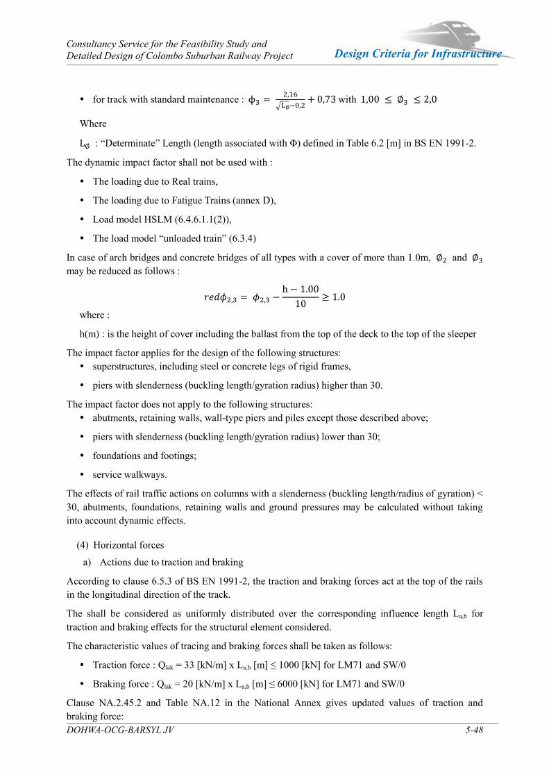
Consultancy Service for the Feasibility Study and Detailed Design of Colombo Suburban Railway Project
DOHWA-OCG-BARSYL JV 5-48
Design Criteria for Infrastructure
for track with standard maintenance : ϕ3 = 2 16
√L∅−0 2+ 0 73 with 1 00 ≤ ∅3 ≤ 2 0
Where
L∅ : “Determinate” Length (length associated with Φ) defined in Table 6.2 [m] in BS EN 1991-2.
The dynamic impact factor shall not be used with :
The loading due to Real trains,
The loading due to Fatigue Trains (annex D),
Load model HSLM (6.4.6.1.1(2)),
The load model “unloaded train” (6.3.4)
In case of arch bridges and concrete bridges of all types with a cover of more than 1.0m, ∅2 and ∅3 may be reduced as follows :
𝑟𝑒𝑑𝜙2 3 = 𝜙2 3 −h − 1.00
10≥ 1.0
where :
h(m) : is the height of cover including the ballast from the top of the deck to the top of the sleeper
The impact factor applies for the design of the following structures: superstructures, including steel or concrete legs of rigid frames,
piers with slenderness (buckling length/gyration radius) higher than 30.
The impact factor does not apply to the following structures: abutments, retaining walls, wall-type piers and piles except those described above;
piers with slenderness (buckling length/gyration radius) lower than 30;
foundations and footings;
service walkways.
The effects of rail traffic actions on columns with a slenderness (buckling length/radius of gyration) < 30, abutments, foundations, retaining walls and ground pressures may be calculated without taking into account dynamic effects.
(4) Horizontal forces
a) Actions due to traction and braking
According to clause 6.5.3 of BS EN 1991-2, the traction and braking forces act at the top of the rails in the longitudinal direction of the track.
The shall be considered as uniformly distributed over the corresponding influence length La,b for traction and braking effects for the structural element considered.
The characteristic values of tracing and braking forces shall be taken as follows:
Traction force : Qlak = 33 [kN/m] x La,b [m] ≤ 1000 [kN] for LM71 and SW/0
Braking force : Qlak = 20 [kN/m] x La,b [m] ≤ 6000 [kN] for LM71 and SW/0
Clause NA.2.45.2 and Table NA.12 in the National Annex gives updated values of traction and braking force:
Consultancy Service for the Feasibility Study and Detailed Design of Colombo Suburban Railway Project
DOHWA-OCG-BARSYL JV 5-49
Design Criteria for Infrastructure
Actions due to traction and braking should be taken as the greater of equations given above, or the following table given in clause NA2.45.2 of NA of BS EN 1991-2.
Table 5-33 Actions due to traction and braking
Note1: The characteristic values of traction and braking forces should not be multiplied by the dynamic factor φ.
Note2: The above traction and braking forces for load models 71 and SW/0 should be multiplied by the factor α (*)
Note3: Sub-clause 6.5.3 (5) of BS EN 1991-2 and NA specify for loaded lengths greater than 300m that additional requirements should be considered for the effects of braking and should be specified by the additional requirements.
Note4: Provisions should be made for the nominal loads due to traction and application of brakes as given below. These loads are considered as acting at rail level in a direction parallel to the tracks. No addition for dynamic effects should be made to the longitudinal loads calculated as specified in this sub-clause.
Note5: For bridges supporting ballasted track, up to one-third of the longitudinal loads may be assumed to be resisted by the tracks outside the bridge structure, provided that no expansion switches or similar rail discontinuities are located on, or within, 18m either end of the bridge.
Note6: Structures and elements carrying single tracks should be designed to carry the larger of the two loads produced by traction and braking in either direction parallel to the track.
Note7: Where a structure or an element carries two tracks, both tracks are considered as being occupied simultaneously. Where the tracks carry traffic in opposite directions, the load due to braking should be applied to one track and the load due to traction to the other. Structures and elements carrying two tracks in the same direction should be subjected to braking or traction on both tracks, whichever gives the greater effect. Consideration should be given to braking and traction, acting in opposite directions, producing rotational effects.
Note8: Where elements carry more than two tracks, longitudinal loads should be considered as applied simultaneously to two tracks only.
Note9: The action due to braking should be limited to 6000 x α, and the action due to traction should be limited to 1000 x α for traction.

Consultancy Service for the Feasibility Study and Detailed Design of Colombo Suburban Railway Project
DOHWA-OCG-BARSYL JV 5-50
Design Criteria for Infrastructure
b) Centrifugal forces
According to clause 6.5.1 of BS EN 1991-2, the centrifugal forces should be taken to act outwards in a horizontal direction at a height of 1.80 m above the running surface in case that the track on a bridge is curved over the whole or part of the length of the bridge.
The characteristic value of the centrifugal force shall be determined according to the equation (6.17) and (6.18) of clause 6.5.1 of BS EN 1991-2. The centrifugal force is defined as a fraction of the vertical load:
𝑄t = v²
gRf 𝑄v =
V²
127Rf 𝑄v;
Where:
v: train speed (m/s)
V: train speed (km/h)
R: track radius (m)
f: is function of the loaded portion of curved track on the bridge LF
For Load Model 71 (and where required Load Model SW/0) the reduction factor f is given by :
f = [1 − V − 120
1000(814
V+ 1 75)(1 − √
2 88
Lf)]
But f > 0,35
For the load models SW/2 and “unloaded train” the value of the reduction factor f should be taken as 1.0.
Figure 5-15 Factor f for Load Model 71 and SW/0 According to Table 6.8 of BS EN 1991-2, load cases for the centrifugal force should be obtained according to factor α = 0.91.
Consultancy Service for the Feasibility Study and Detailed Design of Colombo Suburban Railway Project
DOHWA-OCG-BARSYL JV 5-51
Design Criteria for Infrastructure
c) Noising forces
According to clause 6.5.2 of BS EN 1991-2, the noising force shall be taken as a concentrated force acting horizontally, at the top of the rails, perpendicular to the center-line of track. It shall be applied on both straight track and curved track.
The characteristic value of the nosing force shall be taken as Qsk = 100 kN.
It shall not be multiplied by the factor Φ or by the factor f.
Note1: The characteristic values of the nosing force should not be multiplied by the dynamic factor φ.
Note2: The above nosing force should be multiplied by factor α.
Note3: the nosing force should always be combined with a vertical traffic load.
The noising force should be multiplied by the factor α (α>1). And the noising force shall always be combined with a vertical traffic load.
5.3.7.7 Derailment actions from rail traffic on a railway bridge
According to clause 6.7.1 of BS EN 1991-2, derailment of rail traffic on a railway bridge shall be considered as an Accidental Design Situation. Two design situations shall be considered.
a) Design Situation I : Local damage is allowed under two loads of 0.7 LM71
Derailed vehicles remaining in the track area on the bridge deck with vehicles retained by the adjacent rail or an up stand wall.
For Design Situation I, collapse of a major part of the structure shall be avoided.
Local damage, however, may be tolerated. The parts of the structure concerned shall be designed for the following design loads in the Accidental Design Situation: α x 1.4 x LM 71 (both point loads and uniformly distributed loading, QAId and qAId) parallel to the track in the most unfavorable position inside an area of width 1.5 times the track gauge on either side of the center-line of the track:
Figure 5-16 Derailment load – situation I
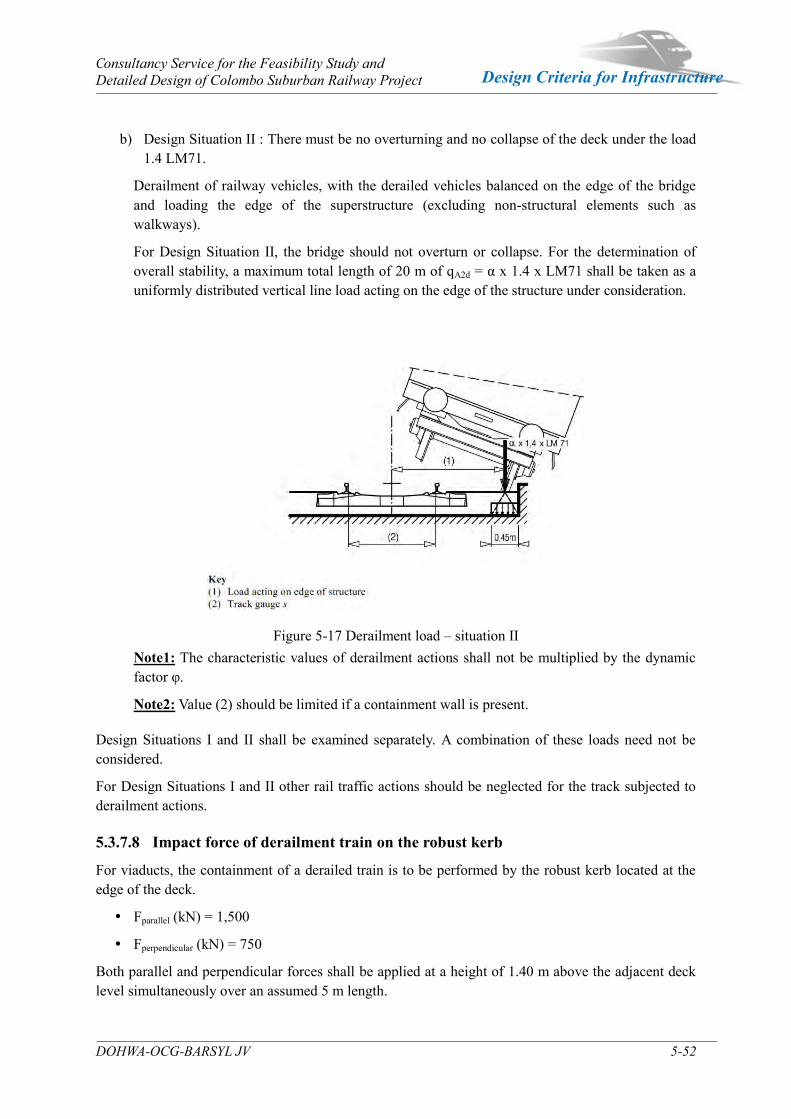
Consultancy Service for the Feasibility Study and Detailed Design of Colombo Suburban Railway Project
DOHWA-OCG-BARSYL JV 5-52
Design Criteria for Infrastructure
b) Design Situation II : There must be no overturning and no collapse of the deck under the load 1.4 LM71.
Derailment of railway vehicles, with the derailed vehicles balanced on the edge of the bridge and loading the edge of the superstructure (excluding non-structural elements such as walkways).
For Design Situation II, the bridge should not overturn or collapse. For the determination of overall stability, a maximum total length of 20 m of qA2d = α x 1.4 x LM71 shall be taken as a uniformly distributed vertical line load acting on the edge of the structure under consideration.
Figure 5-17 Derailment load – situation II Note1: The characteristic values of derailment actions shall not be multiplied by the dynamic factor φ.
Note2: Value (2) should be limited if a containment wall is present. Design Situations I and II shall be examined separately. A combination of these loads need not be considered.
For Design Situations I and II other rail traffic actions should be neglected for the track subjected to derailment actions.
5.3.7.8 Impact force of derailment train on the robust kerb
For viaducts, the containment of a derailed train is to be performed by the robust kerb located at the edge of the deck.
Fparallel (kN) = 1,500
Fperpendicular (kN) = 750
Both parallel and perpendicular forces shall be applied at a height of 1.40 m above the adjacent deck level simultaneously over an assumed 5 m length.

Consultancy Service for the Feasibility Study and Detailed Design of Colombo Suburban Railway Project
DOHWA-OCG-BARSYL JV 5-53
Design Criteria for Infrastructure
5.3.7.9 Live Load for Fatigue
According to clause 9.5.1 and 9.5.3 of BS EN 1993-2, the philosophy of fatigue calculations under railway loads are to calculate the stress variation under LM71 loading with Φ dynamic coefficient, and to multiply it by a factor λ.
And Annex NN of BS EN 1992-2 gives a simplified procedure for calculating the damage equivalent stresses for fatigue verification of superstructures of railway bridges for reinforced concrete and prestressed concrete.
5.3.7.10 Live load pressure for Under bridge and culverts
For rail under bridges and culvert, the effects of the live load pressures are to be taken as follows:
Figure 5-18 Live load pressure on each side of under bridge The pressure coefficient should be taken as ka.
The linear load due to the traffic creates the pressures on the side walls should be taken as 250kN x 4 / 6.4m = 156.25kN/lm, this value should be multiplied by α = 0.91.
5.3.7.11 Actions for non-public footpaths
According to clause 6.3.7 of BS EN 1991-2, actions for non-public footpaths are introduced.
Non-public footpaths are those designated for use by only authorized persons. And pedestrian, cycle and general maintenance loads should be represented by a uniformly distributed load with a characteristic value qfk =5kN/m².
For the design of local elements, a concentrated load Qk = 2kN on a square surface with 200mm side or a concentrated load of 1 kN to a circular area of 100 mm diameter, whichever has the more severe effect.
Horizontal forces on parapets, partition walls and barriers due to persons should be taken as category B or C1 of EN 1991-1-1. According to clause 4.8 of EN 1991-1-1, horizontal handrail loading of 1 kN/m or a horizontal force of 0.5 kN applied at any point to the top rail, whichever has the more severe effect.
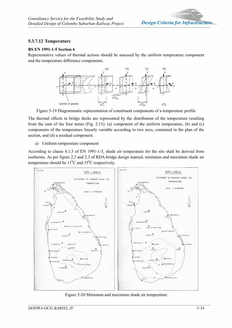
Consultancy Service for the Feasibility Study and Detailed Design of Colombo Suburban Railway Project
DOHWA-OCG-BARSYL JV 5-54
Design Criteria for Infrastructure
5.3.7.12 Temperature
BS EN 1991-1-5 Section 6 Representative values of thermal actions should be assessed by the uniform temperature component and the temperature difference components.
Figure 5-19 Diagrammatic representation of constituent components of a temperature profile
The thermal effects in bridge decks are represented by the distribution of the temperature resulting from the sum of the four terms (Fig. 2.13): (a) component of the uniform temperature, (b) and (c) components of the temperature linearly variable according to two axes, contained in the plan of the section, and (d) a residual component.
a) Uniform temperature component
According to clause 6.1.3 of EN 1991-1-5, shade air temperature for the site shall be derived from isotherms. As per figure 2.2 and 2.3 of RDA bridge design manual, minimum and maximum shade air temperature should be 110C and 350C respectively.
Figure 5-20 Minimum and maximum shade air temperature

Consultancy Service for the Feasibility Study and Detailed Design of Colombo Suburban Railway Project
DOHWA-OCG-BARSYL JV 5-55
Design Criteria for Infrastructure
The values of shade air temperature shall be adjusted for heights above 300m above sea level by subtracting 0.50C per 100m height.
Effective bridge temperatures for different types of construction shall be obtained from the table included in clause 2.2.7 of RDA bridge design manual.
Table 5-34 Effective Bridge Temperatures (Max/Min)
In design consideration, the uniform bridge temperature for each type of structure is given in below table.
Table 5-35 Uniform bridge temperature for each type of structure
Type of superstructures
Effective bridge temperatures
Uniform bridge temperature Remark
Group 1 20℃ ~ 42℃ ±11℃ Steel deck Group 2 19℃ ~ 37℃ ±9℃ Concrete deck
*Note : For climate change impacts, 20C increase of maximum shade air temperature is considered. According to IPCC (Intergovernmental Panel on Climate Change), it is planning to increase gobble warming 1.5 0C in year 2040. Rise in temperature due to global warming can be expected approximately 2 0C in the design life span of the structures.
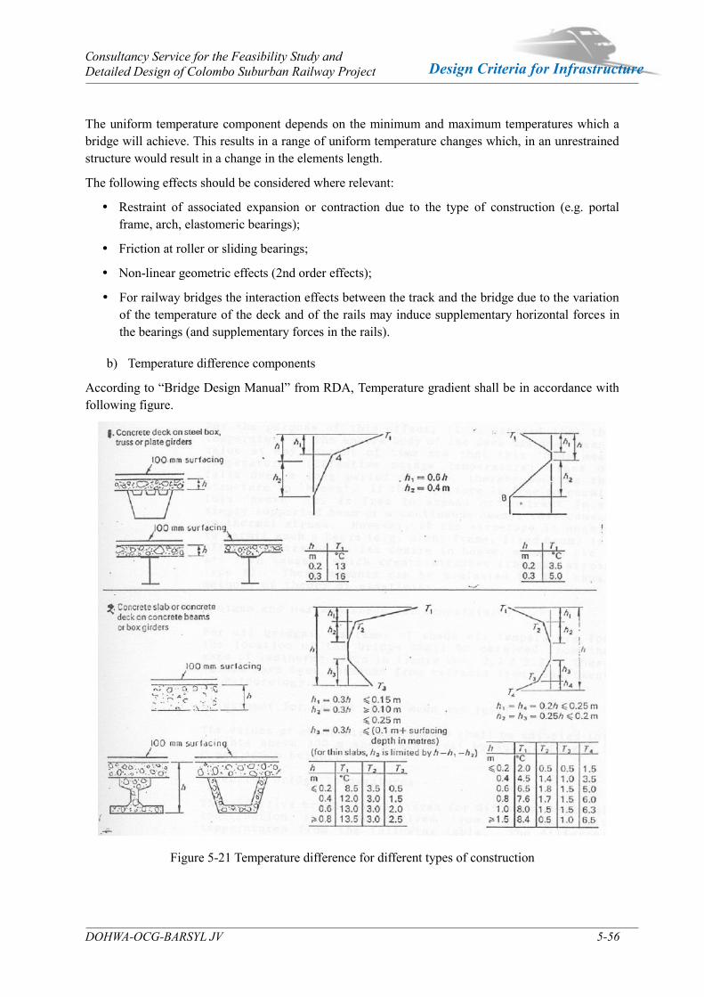
Consultancy Service for the Feasibility Study and Detailed Design of Colombo Suburban Railway Project
DOHWA-OCG-BARSYL JV 5-56
Design Criteria for Infrastructure
The uniform temperature component depends on the minimum and maximum temperatures which a bridge will achieve. This results in a range of uniform temperature changes which, in an unrestrained structure would result in a change in the elements length.
The following effects should be considered where relevant:
Restraint of associated expansion or contraction due to the type of construction (e.g. portal frame, arch, elastomeric bearings);
Friction at roller or sliding bearings;
Non-linear geometric effects (2nd order effects);
For railway bridges the interaction effects between the track and the bridge due to the variation of the temperature of the deck and of the rails may induce supplementary horizontal forces in the bearings (and supplementary forces in the rails).
b) Temperature difference components
According to “Bridge Design Manual” from RDA, Temperature gradient shall be in accordance with following figure.
Figure 5-21 Temperature difference for different types of construction

Consultancy Service for the Feasibility Study and Detailed Design of Colombo Suburban Railway Project
DOHWA-OCG-BARSYL JV 5-57
Design Criteria for Infrastructure
c) Simultaneity of uniform and temperature difference components
According to clause 6.1.5 of BS EN 1991-1-5, both effect of uniform temperature and temperature difference shall be combined to apply a load combination as follow:
ΔTM,heat (or ΔTM,cool) + ωN ΔTN,exp (or ΔTN,con) or
ωM ΔTM,heat (or ΔTM,cool) + ΔTN,exp (or ΔTN,con)
where the most adverse effect should be chosen.
The recommended values for ωN and ωM are ωN = 0.35 and ωM = 0.75.
5.3.7.13 Wind Load
Wind calculations shall be done using 10 minutes mean wind speed according to EN 1991-1-4. Sri Lanka national annex mention 10 minutes mean wind speed 22m/s applicable for normal structures and 25m/s for post disaster structures, because this project site is located in zone 3.
a) Wind velocity and velocity pressure
Wind velocity and velocity pressure SLS NA EN 1991-1-4 Table NA.1
ρ is the density of air (See 4.5) = kg/m3
1) Without Traffic load
Vb is the basic wind speed (See 4.2 (2))
= (Cprob) x Cdir x Cseason x Vb,0 =
= x x x m/s = m/s
Cprob is the probability factor
As per SLS NA EN 1991-1-4, Appendix 2, Probability factor can be clculated based on
the shape factor K=0.2 and exponent n=0.5.
Cdir is the directional factor, see SLS NA EN 1991-1-4, Table NA.1 4.2 (2)
The recommended value is 1.0
Cseason is the season factor, see SLS NA EN 1991-1-4, Table NA.1 4.2 (2)
The recommended value is 1.0
Vb,0 is the fundamental value of the basic wind velocity, see 4.2 (1)
= Vb,zone x Calt = x = m/s
Calt is the altitude correction factor
= 1 + 0.001 A , Calt ≤ 1.5 (Maximum)
Zone (See SLS EN 1991-1-4, Appendix 1 Wind zones map in Sri Lanka)
2) With Traffic load
Vb,0** is the fundamental value of the basic wind velocity with railway traffic load
The recommended value is m/s.
Vb** is the basic wind speed (See 4.2 (2))
= (Cprob) x Cdir x Cseason x Vb,0 =
= x x x m/s = m/s
1.250
1.04 1.0
25.0
1.04 1.0 1.0 25.0 26.0
Zone 3
1.0
22.0 1.5 33.0
= [ ]n =1 - K x ln{-ln(1-p)}
1 - K x ln{-ln(0.98)}1.04
33.0 34.0

Consultancy Service for the Feasibility Study and Detailed Design of Colombo Suburban Railway Project
DOHWA-OCG-BARSYL JV 5-58
Design Criteria for Infrastructure
b) Force in x-direction - Simplified Method
Force in x-direction - Simplified Method EN 1991-1-4 clause 8.3.2Fw = 1/2 x ρ x Vb
2 x C x Aref,x
Aref,x is the reference area given in 8.3.1
C is the wind load factor. C = Ce x Cf,x , where Cf,x is given in 8.3.1 (1)
Ce is the exposure factor given in 4.5
Cfx,0 is the force coefficient without free-end flow (see 8.3.1 (1))
ㆍC, Wind load factor SLS NA EN 1991-1-4, Table NA.1 8.3.2 (1)C is the wind load factor. Refer to SLS NA EN 1991-1-4, Table NA.1 8.3.2 (1)
Ze is the reference height. This value may be taken as the distance
from the lowest ground level to the centre of the bridge deck structure,
disregarding other parts (e.g. parapets) of the reference areas.
Reference height = m
C at Ze
8.0
4.3
30.0
b/dtot Ze ≤ 20 m Ze = 50 m
≤ 0.5 7.4 9.1
≥ 4.0 4.0 4.9
a
0.056667
0.030000
1) Bridge decks without Railway traffic load
① Force in x-direction (Transversal direction)
Fw = 1/2 x 1.25 x (34)^2 x 6.1 x 4.709 = kN/m = kN/m2
② Force in y-direction (Longitudinal direction)
For bridges, 25% of the wind force in transversal direction shall be taken into account
Fw,l = x = kN/m = kN/m2
③ Force in z-direction (Vertical direction)
Fw,v = cf,z·q·Aref,z
cf,z = Lift (or force) coefficient
In the absence of wind tunnel tests, the recommended value may be
taken equal to ± 0.9
q = 1/2 x ρ x Vb2 = 1 / 2 x x 2 =
Fw,v = x x = kN/m = kN/m2
20.8 1.10
1.25 34.0 0.7225
7.1 0.65
dtot
b=
10.900
4.709= 2.31
b/dtot b/dtot ≤ 0.5 b/dtot ≥ 4.0 a C-value
2.31 8.0 4.3 -1.047619 6.1
0.25 5.2
0.9 0.72 10.900
20.8 4.41
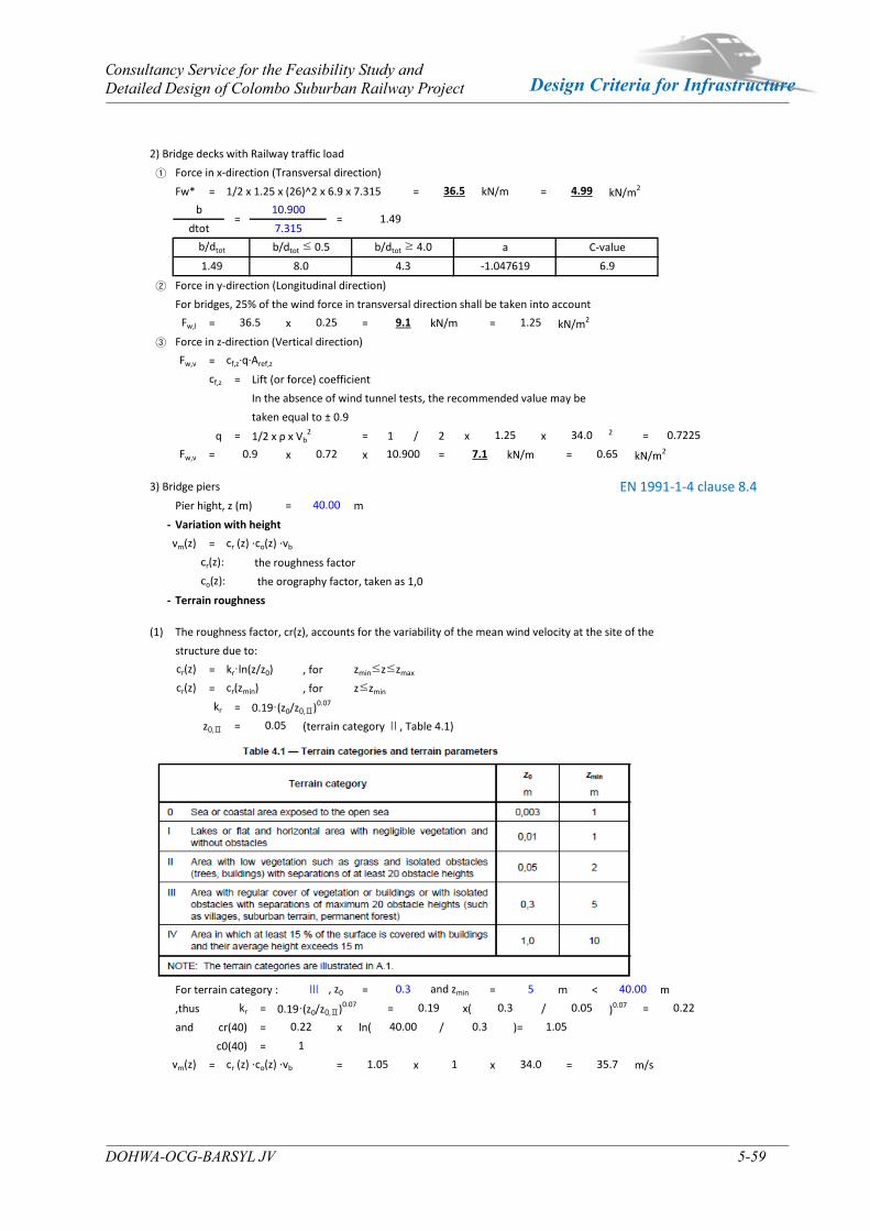
Consultancy Service for the Feasibility Study and Detailed Design of Colombo Suburban Railway Project
DOHWA-OCG-BARSYL JV 5-59
Design Criteria for Infrastructure
2) Bridge decks with Railway traffic load
① Force in x-direction (Transversal direction)
Fw* = 1/2 x 1.25 x (26)^2 x 6.9 x 7.315 = kN/m = kN/m2
② Force in y-direction (Longitudinal direction)
For bridges, 25% of the wind force in transversal direction shall be taken into account
Fw,l = x = kN/m = kN/m2
③ Force in z-direction (Vertical direction)
Fw,v = cf,z·q·Aref,z
cf,z = Lift (or force) coefficient
In the absence of wind tunnel tests, the recommended value may be
taken equal to ± 0.9
q = 1/2 x ρ x Vb2 = 1 / 2 x x 2 =
Fw,v = x x = kN/m = kN/m2
36.5 0.25 9.1 1.25
1.25 34.0 0.7225
0.9 0.72 10.900 7.1 0.65
= 1.49dtot 7.315
b/dtot b/dtot ≤ 0.5 b/dtot ≥ 4.0 a C-value
1.49 8.0 4.3 -1.047619 6.9
36.5 4.99
b=
10.900
3) Bridge piers EN 1991-1-4 clause 8.4Pier hight, z (m) = m
- Variation with height
vm(z) = cr (z) ⋅co(z) ⋅vb
cr(z): the roughness factor
co(z): the orography factor, taken as 1,0
- Terrain roughness
40.00
(1) The roughness factor, cr(z), accounts for the variability of the mean wind velocity at the site of the
structure due to:
cr(z) = kr·ln(z/z0) , for zmin≤z≤zmax
cr(z) = cr(zmin) , for z≤zmin
kr = 0.19·(z0/z0,Ⅱ)0.07
z0,Ⅱ = (terrain category Ⅱ, Table 4.1)
For terrain category : Ⅲ , z0 = and zmin = m < m
,thus kr = 0.19·(z0/z0,Ⅱ)0.07 = x( / )0.07 =
and cr(40) = x ln( / )=
c0(40) =
vm(z) = cr (z) ⋅co(z) ⋅vb = x x = m/s
0.05 0.22
0.22
1
1.05 1 34.0 35.7
40.00 0.3 1.05
0.05
0.3 5 40.00
0.19 0.3
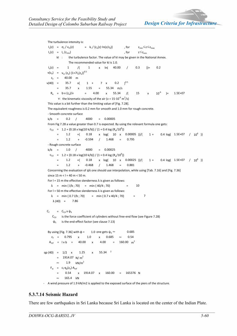
Consultancy Service for the Feasibility Study and Detailed Design of Colombo Suburban Railway Project
DOHWA-OCG-BARSYL JV 5-60
Design Criteria for Infrastructure
5.3.7.14 Seismic Hazard
There are few earthquakes in Sri Lanka because Sri Lanka is located on the center of the Indian Plate.
The turbulence intensity is:
Iv(z) = σv / vm(z) = kI / {co(z)·ln(z/z0)} , for zmin≤z≤zmax
Iv(z) = Iv (zmin) , for z≤zmin
kI : the turbulence factor. The value of kI may be given in the National Annex.
The recommended value for kI is 1.0.
Iv(z) = /{ x ln( / )}=
v(ze) = vm (ze) {1+7Iv(ze)}0.5
ze = m
v(40) = x{ 1 + 7 x }0.5
= x = m/s
Re = b·v (ze)/ν = x /( x )=
ν: the kinematic viscosity of the air (ν = 15·10-6 m2/s)
This value is a bit further than the limiting value of [Fig. 7.28].
The equivalent roughness is 0.2 mm for smooth and 1.0 mm for rough concrete.
- Smooth concrete surface
k/b = / =
From Fig 7.28 a value greater than 0.7 is expected. By using the relevant formula one gets:
cf,0 = 1.2 + {0.18 x log(10 k/b)} / {1 + 0.4 log (Re/106)}
= +{ x log( 10 x )}/{ 1 + 0.4 log( / 106 )}
= + / =
- Rough concrete surface
k/b = / =
cf,0 = 1.2 + {0.18 x log(10 k/b)} / {1 + 0.4 log (Re/106)}
= +{ x log( 10 x )}/{ 1 + 0.4 log( / 106 )}
= + / =
Concerning the evaluation of ψλ one should use interpolation, while using [Tab. 7.16] and [Fig. 7.36]
since 15 m < l = 40 m < 50 m.
For l = 15 m the effective slenderness λ is given as follows:
λ = min { l/b ; 70} = min { 40/4 ; 70} =
For l = 50 m the effective slenderness λ is given as follows:
λ = min { 0.7 l/b ; 70} = min { 0.7 x 40/4 ; 70} =
λ (40) =
Cf = Cf,0 x ψλ
Cf,0 is the force coefficient of cylinders without free-end flow (see Figure 7.28)
ψλ is the end-effect factor (see clause 7.13)
By using [Fig. 7.36] with φ = 1.0 one gets ψλ ≈
cf = x x ≈
Aref = l x b = x = m2
qp (40) = 1/2 x x 2
= N/ m2
≈ kN/m2
Fw = cf·qp(ze)·Aref
= x x = N
≈ kN
- A wind pressure of 1.9 kN/m2 is applied to the exposed surface of the piers of the structure.
165.4
7
7.86
0.685
0.795 1.0 0.685 0.54
40.00 4.00 160.00
1.25 55.34
1.2 -0.594 1.468 0.795
1.0 4000 0.00025
1.2 0.18 0.00025 1.5E+07
1914.07
1.9
0.54 1914.07 160.00 165376
10
40.00
35.7 0.2
55.34
4.00 55.34 15 10-6 1.5E+07
0.2 4000 0.00005
1.2 0.18 0.00005 1.5E+07
1 1 40.00 0.3 0.2
35.7 1.55
1.2 -0.468 1.468 0.881
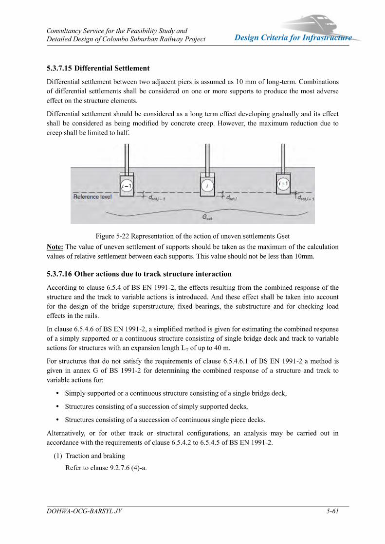
Consultancy Service for the Feasibility Study and Detailed Design of Colombo Suburban Railway Project
DOHWA-OCG-BARSYL JV 5-61
Design Criteria for Infrastructure
5.3.7.15 Differential Settlement
Differential settlement between two adjacent piers is assumed as 10 mm of long-term. Combinations of differential settlements shall be considered on one or more supports to produce the most adverse effect on the structure elements.
Differential settlement should be considered as a long term effect developing gradually and its effect shall be considered as being modified by concrete creep. However, the maximum reduction due to creep shall be limited to half.
Figure 5-22 Representation of the action of uneven settlements Gset Note: The value of uneven settlement of supports should be taken as the maximum of the calculation values of relative settlement between each supports. This value should not be less than 10mm.
5.3.7.16 Other actions due to track structure interaction
According to clause 6.5.4 of BS EN 1991-2, the effects resulting from the combined response of the structure and the track to variable actions is introduced. And these effect shall be taken into account for the design of the bridge superstructure, fixed bearings, the substructure and for checking load effects in the rails.
In clause 6.5.4.6 of BS EN 1991-2, a simplified method is given for estimating the combined response of a simply supported or a continuous structure consisting of single bridge deck and track to variable actions for structures with an expansion length LT of up to 40 m.
For structures that do not satisfy the requirements of clause 6.5.4.6.1 of BS EN 1991-2 a method is given in annex G of BS 1991-2 for determining the combined response of a structure and track to variable actions for:
Simply supported or a continuous structure consisting of a single bridge deck,
Structures consisting of a succession of simply supported decks,
Structures consisting of a succession of continuous single piece decks.
Alternatively, or for other track or structural configurations, an analysis may be carried out in accordance with the requirements of clause 6.5.4.2 to 6.5.4.5 of BS EN 1991-2.
(1) Traction and braking
Refer to clause 9.2.7.6 (4)-a.
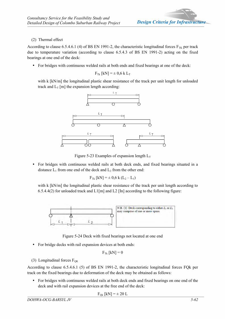
Consultancy Service for the Feasibility Study and Detailed Design of Colombo Suburban Railway Project
DOHWA-OCG-BARSYL JV 5-62
Design Criteria for Infrastructure
(2) Thermal effect
According to clause 6.5.4.6.1 (4) of BS EN 1991-2, the characteristic longitudinal forces FTK per track due to temperature variation (according to clause 6.5.4.3 of BS EN 1991-2) acting on the fixed bearings at one end of the deck:
For bridges with continuous welded rails at both ends and fixed bearings at one of the deck:
FTk [kN] = ± 0,6 k LT
with k [kN/m] the longitudinal plastic shear resistance of the track per unit length for unloaded track and LT [m] the expansion length according:
Figure 5-23 Examples of expansion length LT
For bridges with continuous welded rails at both deck ends, and fixed bearings situated in a distance L1 from one end of the deck and L2 from the other end:
FTk [kN] = ± 0,6 k (L2 – L1)
with k [kN/m] the longitudinal plastic shear resistance of the track per unit length according to 6.5.4.4(2) for unloaded track and L1[m] and L2 [In] according to the following figure:
Figure 5-24 Deck with fixed bearings not located at one end
For bridge decks with rail expansion devices at both ends:
FTk [kN] = 0
(3) Longitudinal forces FQK
According to clause 6.5.4.6.1 (5) of BS EN 1991-2, the characteristic longitudinal forces FQk per track on the fixed bearings due to deformation of the deck may be obtained as follows:
For bridges with continuous welded rails at both deck ends and fixed bearings on one end of the deck and with rail expansion devices at the free end of the deck:
FQk [kN] = ± 20 L
Consultancy Service for the Feasibility Study and Detailed Design of Colombo Suburban Railway Project
DOHWA-OCG-BARSYL JV 5-63
Design Criteria for Infrastructure
with L [m] the length of the first span near the fixed bearing
For bridges with rail expansion devices at both ends of the deck:
FQk [kN] = 0
Note: The vertical displacement of the upper surface of a deck relative to the adjacent construction (abutment or another deck) due to variable actions may be calculated ignoring the combined response of the structure and track and checked against the criteria in clause 6.5.4.5.2(3) of BS EN 1991-2.
5.3.7.17 Bearing Replacement
In the case of the replacement of bearings, the deck shall be resist at the time of bearing replacement.
This takes place without traffic for the railway works. In this project, the lifting dimension of the deck at the replacement of bearing location is assumed to 10 mm.
5.3.7.18 Friction from Bearings
The railway bridges supported by bearing are generally supported both by restraint pot bearings and sliding pot bearings, the horizontal force taken up by the restraint pot bearings is obtained by taking account of the longitudinal and transversal equilibrium of the structure.
According to clause 3.5 of BS EN 1993-2, bearings should conform to EN 1337.
(1) Reaction to rolling and sliding a set of bearings
According to clause 6 of EN 1337-1, where a number of bearings are so arranged that the adverse forces, resulting from reaction to movement by some, are partly relieve by the forces resulting from the reaction to movement by others, the respective coefficients of friction μa and μr shall be estimated in the following manner, unless a more precise investigation has been made:
μa = 0,5 μmax (1+α)
μr = 0,5 μmax (1-α)
where :
μa : is the averse coefficient of friction;
μr : is the relieving coefficient of friction;
μmax : is the maximum coefficient of friction for bearings as given in other Parts of European Standard;
α : is a factor dependent on the type of bearing and the number of bearings which are exerting either an adverse or relieving force as appropriate; if a value for “α” is not given it shall be calculated in accordance with the following table:
Table 5-36 Factor αn, dependent on the type of bearing and the number of bearings n αn
≤ 4 1 4 < n < 10 (16-n)/12
N ≥ 10 0,5

Consultancy Service for the Feasibility Study and Detailed Design of Colombo Suburban Railway Project
DOHWA-OCG-BARSYL JV 5-64
Design Criteria for Infrastructure
(2) Coefficient of Friction
According to clause 6.7 of EN 1337-2, the coefficient of friction μmax given in following table shall be used for verification of the bearing and the structure in which it is incorporated.
Intermediate values can be obtained by linear interpolation or by using formula given in annex B of EN 1337-2.
The effects of friction shall not be used to relieve the effects of externally applied horizontal loads.
The values shown in following table are valid only for dimpled lubricated PTFE.
Table 5-37 Coefficients of friction μmax Contact pressure
(MPa) ≤ 5 10 20 ≥ 30
PTFE dimpled/austenitic steel or hard chrominum plating 0,08 0,06 0,04 0,03
(0,025)a
PTFE dimpled / aluminum alloy anodized 0,12 0,09 0,06 0,045
(0,038)a
a These values apply to the frictional resistance of curved sliding surfaces. For guides with a combination of sliding materials given in the third column of Table 8 of EN 1337-2, the coefficient of friction shall be considered to be independent of contact pressure and the following values shall be used:
PTFE : μmax = 0.08
Composite materials : μmax = 0.20
Bearing friction shall be considered in accordance with BS EN 1991-1-5. Actions due to starting friction on moving surfaces shall be determined from the bearing manufactures‟ specification.
These values are for newly fabricated elements and an allowance for long term degradation of sliding surfaces should be accommodated by increasing friction coefficient values by 50%.
(3) Combination for bearings
Frictional forces at bearings may be treated as a variable action and considered in combination with other actions defined in BS EN 1990 and BS 1991.
5.3.7.19 Accidental actions
The accidental actions due to the following events can be occurred.
Impact from road vehicles (clause 4.3 of BS EN 1991-1-7 & NA to SLS EN 1991-1-7)
Impact from ships (clause 4.6 of BS EN 1991-1-7 & NA to SLS EN 1991-1-7)
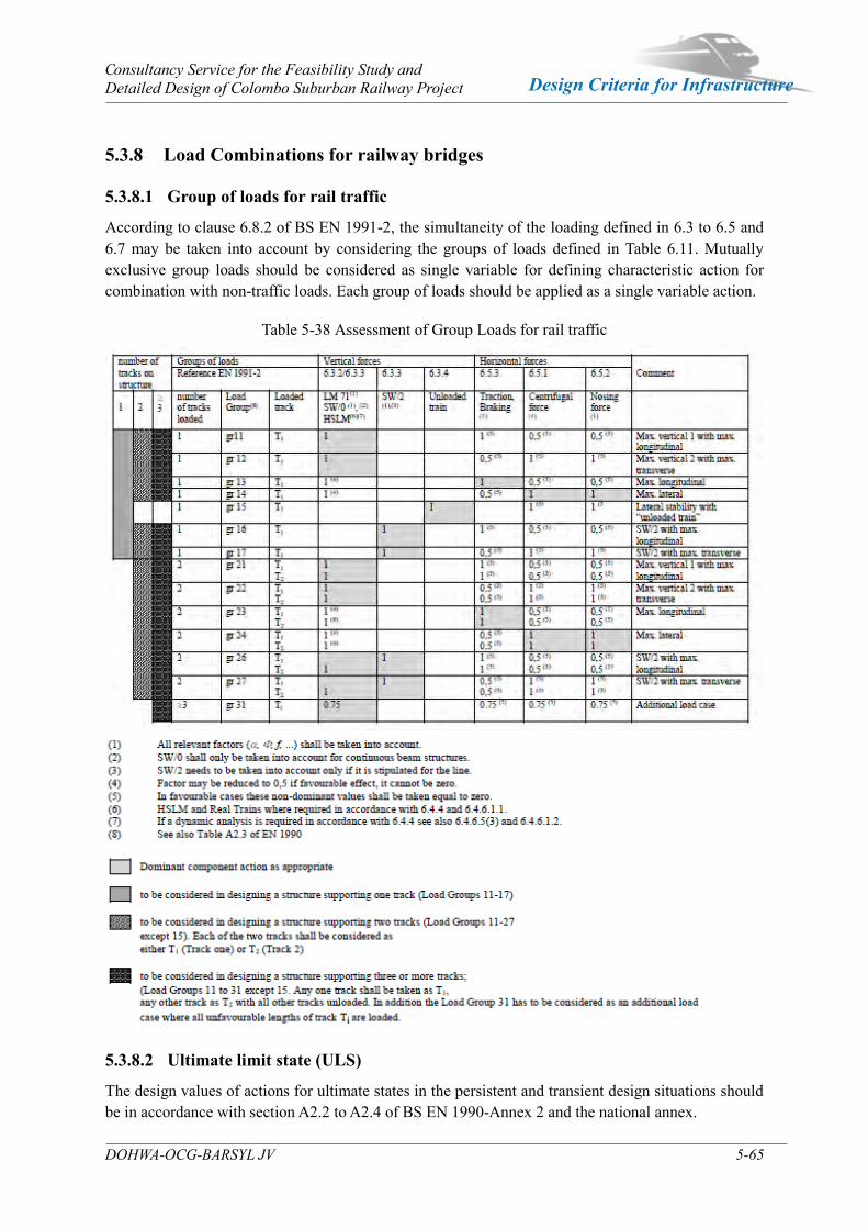
Consultancy Service for the Feasibility Study and Detailed Design of Colombo Suburban Railway Project
DOHWA-OCG-BARSYL JV 5-65
Design Criteria for Infrastructure
5.3.8 Load Combinations for railway bridges
5.3.8.1 Group of loads for rail traffic
According to clause 6.8.2 of BS EN 1991-2, the simultaneity of the loading defined in 6.3 to 6.5 and 6.7 may be taken into account by considering the groups of loads defined in Table 6.11. Mutually exclusive group loads should be considered as single variable for defining characteristic action for combination with non-traffic loads. Each group of loads should be applied as a single variable action.
Table 5-38 Assessment of Group Loads for rail traffic
5.3.8.2 Ultimate limit state (ULS)
The design values of actions for ultimate states in the persistent and transient design situations should be in accordance with section A2.2 to A2.4 of BS EN 1990-Annex 2 and the national annex.
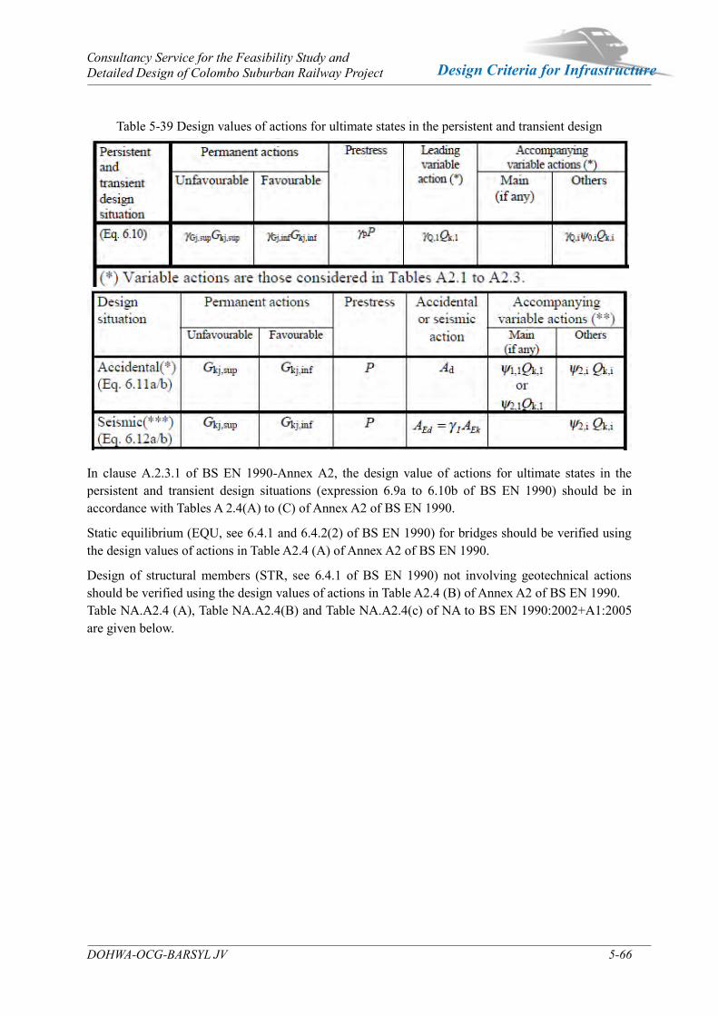
Consultancy Service for the Feasibility Study and Detailed Design of Colombo Suburban Railway Project
DOHWA-OCG-BARSYL JV 5-66
Design Criteria for Infrastructure
Table 5-39 Design values of actions for ultimate states in the persistent and transient design
In clause A.2.3.1 of BS EN 1990-Annex A2, the design value of actions for ultimate states in the persistent and transient design situations (expression 6.9a to 6.10b of BS EN 1990) should be in accordance with Tables A 2.4(A) to (C) of Annex A2 of BS EN 1990.
Static equilibrium (EQU, see 6.4.1 and 6.4.2(2) of BS EN 1990) for bridges should be verified using the design values of actions in Table A2.4 (A) of Annex A2 of BS EN 1990.
Design of structural members (STR, see 6.4.1 of BS EN 1990) not involving geotechnical actions should be verified using the design values of actions in Table A2.4 (B) of Annex A2 of BS EN 1990. Table NA.A2.4 (A), Table NA.A2.4(B) and Table NA.A2.4(c) of NA to BS EN 1990:2002+A1:2005 are given below.

Consultancy Service for the Feasibility Study and Detailed Design of Colombo Suburban Railway Project
DOHWA-OCG-BARSYL JV 5-67
Design Criteria for Infrastructure
Table 5-40 Design values of actions (EQU) (Set A)
Details about partial factor for actions are given in Note 1 ~ 10 of Table NA.A.2.4 (A) of NA to SLS EN 1990:2018.
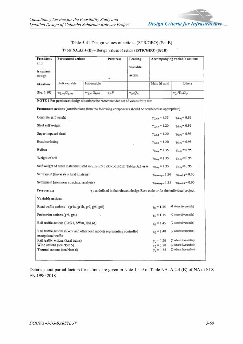
Consultancy Service for the Feasibility Study and Detailed Design of Colombo Suburban Railway Project
DOHWA-OCG-BARSYL JV 5-68
Design Criteria for Infrastructure
Table 5-41 Design values of actions (STR/GEO) (Set B)
Details about partial factors for actions are given in Note 1 ~ 9 of Table NA. A.2.4 (B) of NA to SLS EN 1990:2018.
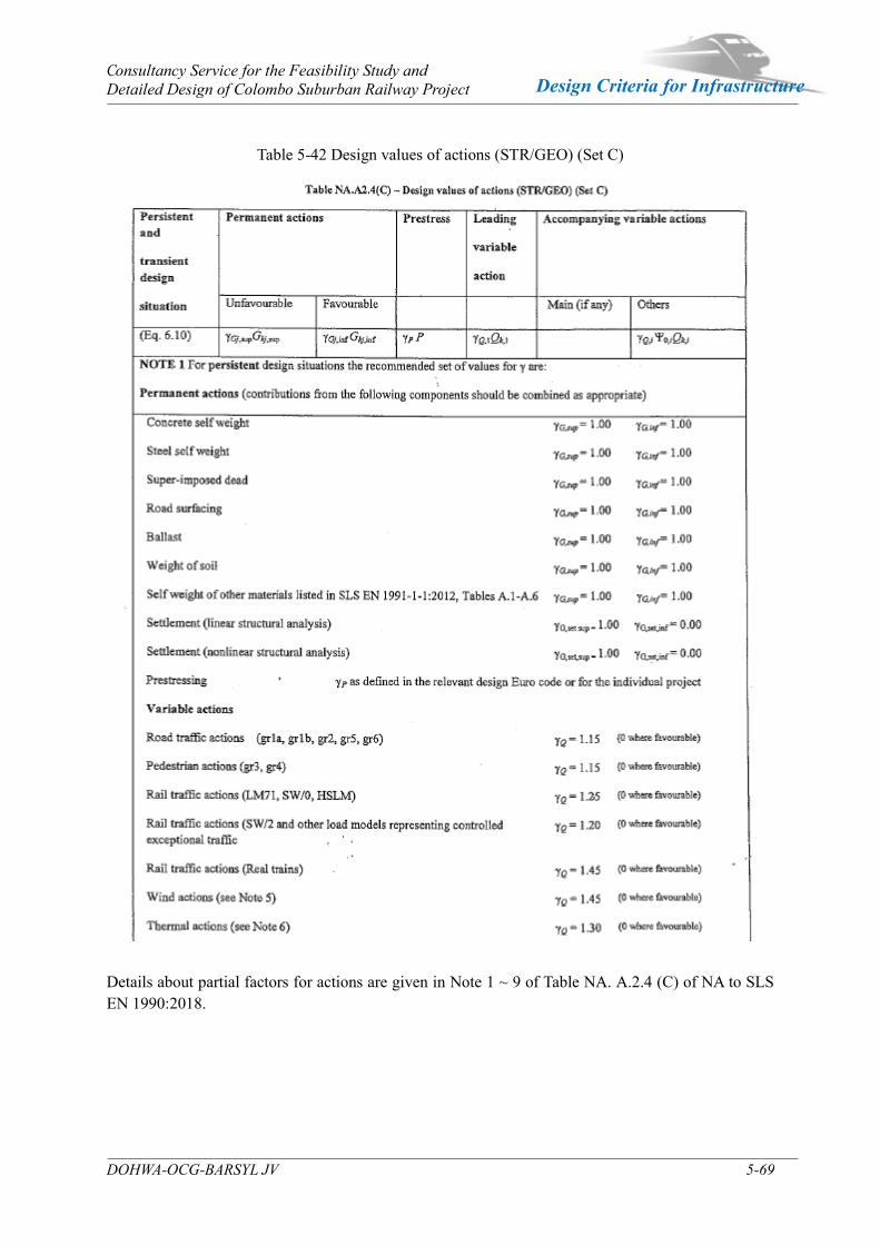
Consultancy Service for the Feasibility Study and Detailed Design of Colombo Suburban Railway Project
DOHWA-OCG-BARSYL JV 5-69
Design Criteria for Infrastructure
Table 5-42 Design values of actions (STR/GEO) (Set C)
Details about partial factors for actions are given in Note 1 ~ 9 of Table NA. A.2.4 (C) of NA to SLS EN 1990:2018.
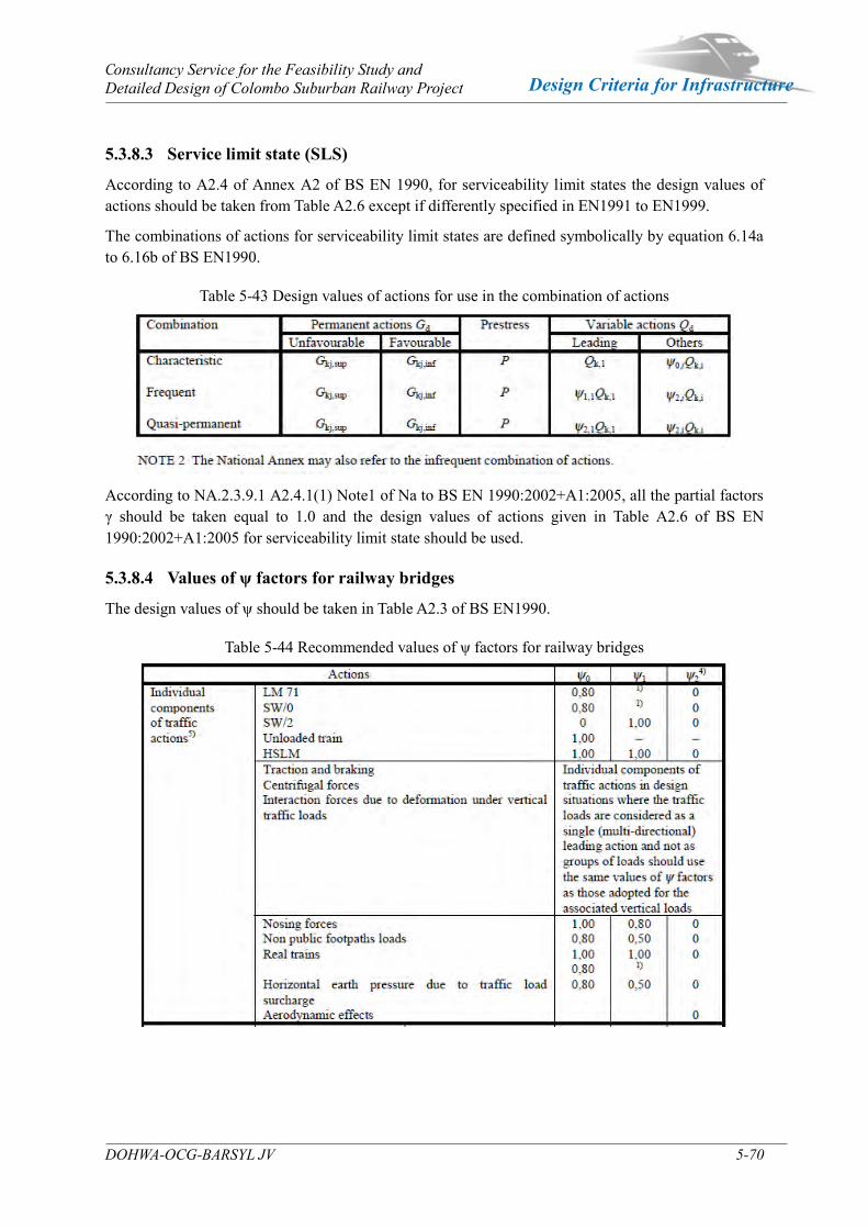
Consultancy Service for the Feasibility Study and Detailed Design of Colombo Suburban Railway Project
DOHWA-OCG-BARSYL JV 5-70
Design Criteria for Infrastructure
5.3.8.3 Service limit state (SLS)
According to A2.4 of Annex A2 of BS EN 1990, for serviceability limit states the design values of actions should be taken from Table A2.6 except if differently specified in EN1991 to EN1999.
The combinations of actions for serviceability limit states are defined symbolically by equation 6.14a to 6.16b of BS EN1990.
Table 5-43 Design values of actions for use in the combination of actions
According to NA.2.3.9.1 A2.4.1(1) Note1 of Na to BS EN 1990:2002+A1:2005, all the partial factors γ should be taken equal to 1.0 and the design values of actions given in Table A2.6 of BS EN 1990:2002+A1:2005 for serviceability limit state should be used.
5.3.8.4 Values of ψ factors for railway bridges
The design values of ψ should be taken in Table A2.3 of BS EN1990.
Table 5-44 Recommended values of ψ factors for railway bridges
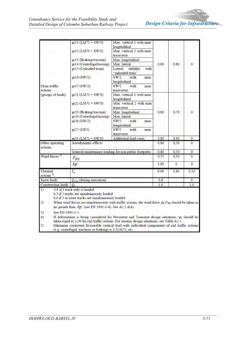
Consultancy Service for the Feasibility Study and Detailed Design of Colombo Suburban Railway Project
DOHWA-OCG-BARSYL JV 5-71
Design Criteria for Infrastructure
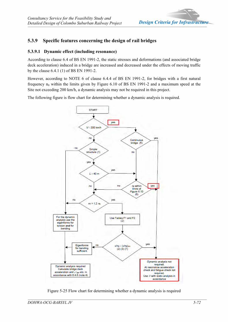
Consultancy Service for the Feasibility Study and Detailed Design of Colombo Suburban Railway Project
DOHWA-OCG-BARSYL JV 5-72
Design Criteria for Infrastructure
5.3.9 Specific features concerning the design of rail bridges
5.3.9.1 Dynamic effect (including resonance)
According to clause 6.4 of BS EN 1991-2, the static stresses and deformations (and associated bridge deck acceleration) induced in a bridge are increased and decreased under the effects of moving traffic by the clause 6.4.1 (1) of BS EN 1991-2.
However, according to NOTE 6 of clause 6.4.4 of BS EN 1991-2, for bridges with a first natural frequency n0 within the limits given by Figure 6.10 of BS EN 1991-2 and a maximum speed at the Site not exceeding 200 km/h, a dynamic analysis may not be required in this project.
The following figure is flow chart for determining whether a dynamic analysis is required.
Figure 5-25 Flow chart for determining whether a dynamic analysis is required
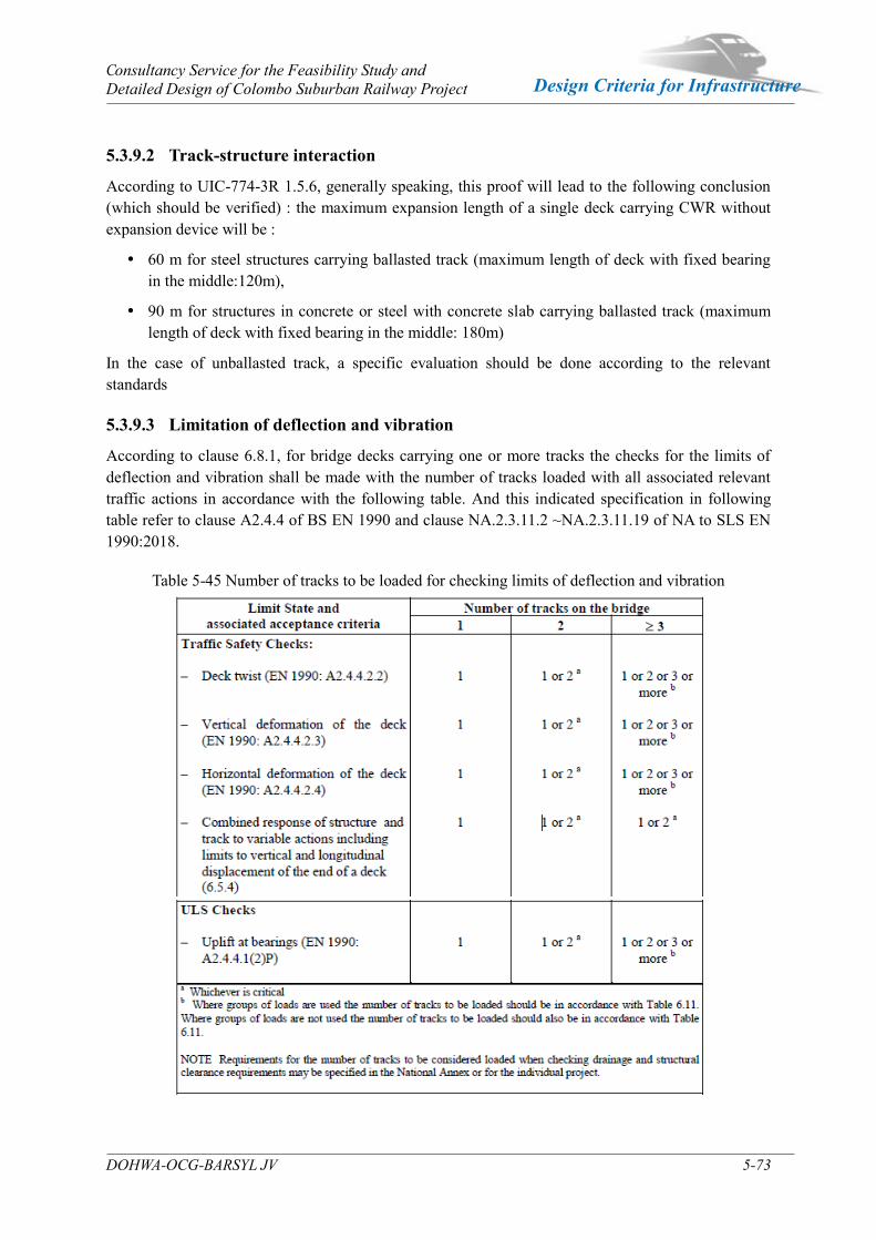
Consultancy Service for the Feasibility Study and Detailed Design of Colombo Suburban Railway Project
DOHWA-OCG-BARSYL JV 5-73
Design Criteria for Infrastructure
5.3.9.2 Track-structure interaction
According to UIC-774-3R 1.5.6, generally speaking, this proof will lead to the following conclusion (which should be verified) : the maximum expansion length of a single deck carrying CWR without expansion device will be :
60 m for steel structures carrying ballasted track (maximum length of deck with fixed bearing in the middle:120m),
90 m for structures in concrete or steel with concrete slab carrying ballasted track (maximum length of deck with fixed bearing in the middle: 180m)
In the case of unballasted track, a specific evaluation should be done according to the relevant standards
5.3.9.3 Limitation of deflection and vibration
According to clause 6.8.1, for bridge decks carrying one or more tracks the checks for the limits of deflection and vibration shall be made with the number of tracks loaded with all associated relevant traffic actions in accordance with the following table. And this indicated specification in following table refer to clause A2.4.4 of BS EN 1990 and clause NA.2.3.11.2 ~NA.2.3.11.19 of NA to SLS EN 1990:2018.
Table 5-45 Number of tracks to be loaded for checking limits of deflection and vibration
6 Track Design
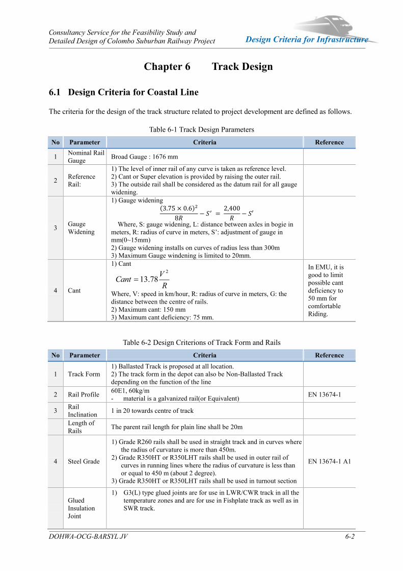
Consultancy Service for the Feasibility Study and Detailed Design of Colombo Suburban Railway Project
DOHWA-OCG-BARSYL JV 6-2
Design Criteria for Infrastructure
Chapter 6 Track Design
6.1 Design Criteria for Coastal Line
The criteria for the design of the track structure related to project development are defined as follows.
Table 6-1 Track Design Parameters
No Parameter Criteria Reference
1 Nominal Rail Gauge Broad Gauge : 1676 mm
2 Reference Rail:
1) The level of inner rail of any curve is taken as reference level. 2) Cant or Super elevation is provided by raising the outer rail. 3) The outside rail shall be considered as the datum rail for all gauge widening.
3 Gauge Widening
1) Gauge widening ( )
Where, S: gauge widening, L: distance between axles in bogie in meters, R: radius of curve in meters, S’: adjustment of gauge in mm(0~15mm) 2) Gauge widening installs on curves of radius less than 300m 3) Maximum Gauge windening is limited to 20mm.
4 Cant
1) Cant
R
VCant2
78.13
Where, V: speed in km/hour, R: radius of curve in meters, G: the distance between the centre of rails. 2) Maximum cant: 150 mm 3) Maximum cant deficiency: 75 mm.
In EMU, it is good to limit possible cant deficiency to 50 mm for comfortable Riding.
Table 6-2 Design Criterions of Track Form and Rails
No Parameter Criteria Reference
1 Track Form 1) Ballasted Track is proposed at all location. 2) The track form in the depot can also be Non-Ballasted Track depending on the function of the line
2 Rail Profile 60E1, 60kg/m - material is a galvanized rail(or Equivalent) EN 13674-1
3 Rail Inclination 1 in 20 towards centre of track
Length of Rails The parent rail length for plain line shall be 20m
4 Steel Grade
1) Grade R260 rails shall be used in straight track and in curves where the radius of curvature is more than 450m.
2) Grade R350HT or R350LHT rails shall be used in outer rail of curves in running lines where the radius of curvature is less than or equal to 450 m (about 2 degree).
3) Grade R350HT or R350LHT rails shall be used in turnout section
EN 13674-1 A1
Glued Insulation Joint
1) G3(L) type glued joints are for use in LWR/CWR track in all the temperature zones and are for use in Fishplate track as well as in SWR track.

Consultancy Service for the Feasibility Study and Detailed Design of Colombo Suburban Railway Project
DOHWA-OCG-BARSYL JV 6-3
Design Criteria for Infrastructure
No Parameter Criteria Reference Table6-2-1 Type of Glued Joint
Rail Section End Post Thickness Length(L) Type
60kg(60E1) 6 mm L≥950mm for 6 bolts G3(L)
Table 6-3 Design Criterions of Rail Fastener
No Parameter Criteria Reference
1 Clips
Main and Depot tracks: 1) Type: Elastic resilient fastening type 2) Material: Silico Manganese spring steel
/Galvanized(or Equivealent) 3) Toe-load: 1150±100kg 4) Toe-deflection: 11 mm
IRS T-31
2 Insulating GFN Liner
Materials: Insulators shall be made from glass filled nylon-66 IRS T-44
3 Rail Pad
Materials: The grooved rubber sole plate shall be manufactured using natural rubber, Ribbed Smoked Sheet (RSS) either of grade 1 to 4 or equivnent.
Minimum Thickness: 6mm or more
Table 6-4 Design Criterions of Sleepers
No Parameter Criteria Reference
1 Sleeper Type 1). Prestressed Concrete Monoblock 2). In the curved section, the sleeper should consider to install the
gauge widening(slack)and the guard (check)rail, etc. IRS T-39
2 Dimension of Sleepers
1) PC sleeper length: 2750 mm 2) PC sleeper for height at rail seat: 210 mm
Table 6-5 Design Criterions of Turnouts
No Parameter Criteria Reference
1 Turnout Type 60E1 rail of turnout
(cast manganese Steel and point with thick web curved elastic tongue rail)
IRS T-10
2 Application of Turnout
1) Main Track : 1IN12 and 1IN8.5 2) Depot Track: 1IN8.5
3 Bearers of Turnout Type: Pre-stressed concrete sleepers for turnouts IRS T-45
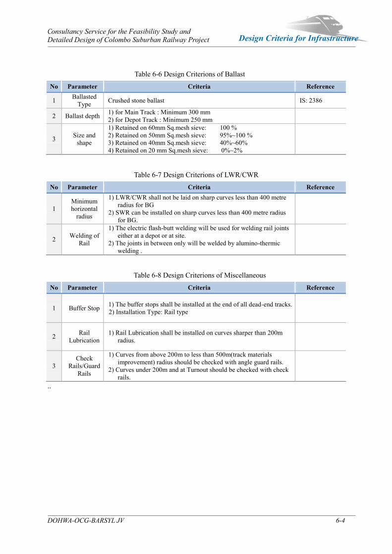
Consultancy Service for the Feasibility Study and Detailed Design of Colombo Suburban Railway Project
DOHWA-OCG-BARSYL JV 6-4
Design Criteria for Infrastructure
Table 6-6 Design Criterions of Ballast
No Parameter Criteria Reference
1 Ballasted Type Crushed stone ballast IS: 2386
2 Ballast depth 1) for Main Track : Minimum 300 mm 2) for Depot Track : Minimum 250 mm
3 Size and shape
1) Retained on 60mm Sq.mesh sieve: 100 % 2) Retained on 50mm Sq.mesh sieve: 95%~100 % 3) Retained on 40mm Sq.mesh sieve: 40%~60% 4) Retained on 20 mm Sq.mesh sieve: 0%~2%
Table 6-7 Design Criterions of LWR/CWR
No Parameter Criteria Reference
1 Minimum horizontal
radius
1) LWR/CWR shall not be laid on sharp curves less than 400 metre radius for BG
2) SWR can be installed on sharp curves less than 400 metre radius for BG.
2 Welding of Rail
1) The electric flash-butt welding will be used for welding rail joints either at a depot or at site.
2) The joints in between only will be welded by alumino-thermic welding .
Table 6-8 Design Criterions of Miscellaneous
No Parameter Criteria Reference
1 Buffer Stop 1) The buffer stops shall be installed at the end of all dead-end tracks. 2) Installation Type: Rail type
2 Rail Lubrication
1) Rail Lubrication shall be installed on curves sharper than 200m radius.
3 Check
Rails/Guard Rails
1) Curves from above 200m to less than 500m(track materials improvement) radius should be checked with angle guard rails.
2) Curves under 200m and at Turnout should be checked with check rails.
..