design criteria and specifications for gravity sewers …
TRANSCRIPT
DESIGN CRITERIA AND SPECIFICATIONS
FOR
GRAVITY SEWERS AND APPURTENANCES
TULLAHOMA UTILITIES AUTHORITY
SPECIFICATIONS NO. TUA-S-694 REVISION 6
DECEMBER 2017
i
TULLAHOMA UTILITIES AUTHORITY
DESIGN CRITERIA AND SPECIFICATIONS FOR
GRAVITY SEWERS AND APPURTENANCES
ITEM SECTION PAGE NO.
GENERAL INFORMATION ......................................................1 1
Definitions...........................................................................1.01 1
Scope of Regulations ..........................................................1.02 1
References ...........................................................................1.03 1
Design Features ...................................................................1.04 2
Permits ................................................................................1.05 5
Notification of Construction ...............................................1.06 5
Inspection ............................................................................1.07 5
Final Acceptance .................................................................1.08 5
MATERIALS ................................................................................2 6
General ................................................................................2.01 6
Concrete ..............................................................................2.02 6
Crushed Stone .....................................................................2.03 7
Pea Gravel ...........................................................................2.04 7
Manhole Frames and Covers ..............................................2.05 7
Manhole Steps .....................................................................2.06 7
Precast Manholes ................................................................2.07 7
Monolithic Poured-In-Place Manholes ...............................2.08 8
Resilient Connectors ...........................................................2.09 9
Ductile Iron Sewer Pipe ......................................................2.10 10
Polyvinyl Chloride (PVC) Sewer Pipe ...............................2.11 10
Concrete Pipe and Other Materials .....................................2.12 12
Fittings and Couplings ........................................................2.13 12
Special Note on Testing and Inspections ............................2.14 12
Identification Tape………………………………………...2.15 12
CONSTRUCTION ........................................................................3 12
General ................................................................................3.01 12
Trench Excavation ..............................................................3.02 13
Installation of Sewer Pipe and Accessories ........................3.03 15
Manholes .............................................................................3.04 19
Service Connections............................................................3.05 20
Water Migration Dams .......................................................3.06 20
Backfill ................................................................................3.07 21
Pavement Removal .............................................................3.08 22
Pavement Replacement .......................................................3.09 22
Clean-Up Procedures and Requirements ............................3.10 23
TESTING .......................................................................................4 23
ii
General ...............................................................................4.01 23
Visual Inspection ................................................................4.02 24
Leakage Tests......................................................................4.03 24
Deflection Testing ...............................................................4.04 25
Manhole Vacuum Testing ...................................................4.05 26
STANDARD DETAIL DRAWINGS...........................................S-1 through S-7 - 27-33
1
SECTION 1 - GENERAL INFORMATION
1.01 DEFINITIONS
TUA - Tullahoma Utilities Authority, or Authorized Agent
City - City of Tullahoma, Coffee County, Tennessee
Developer - Owner of proposed development in which sewer lines are to be located.
Contractor - Contractor who is installing sewer lines in a proposed development. As
provided by the laws of Tennessee, he must be properly licensed in
Tennessee to perform gravity sewer work and must have shown
competency in pervious work.
Engineer - One who has prepared the construction plans for the installation of sewer
lines in a proposed development. As provided by the laws of Tennessee,
he must be a registered professional engineer in Tennessee and plans and
specifications must bear his official seal. He must have demonstrated
competency in design of gravity sewage systems
1.02 SCOPE OF REGULATIONS
These regulations shall apply to any person, developer, firm, business, or entity interested in and
desiring to construct additional sewer lines or to extend sewer lines within the City of
Tullahoma, Tennessee, or to construct additional lines or extend sewer lines in a way that affects
the sewer service provided by the City.
1.03 REFERENCES
The Engineer and Developer should be familiar with the contents of the following documents
prior to plans submission to TUA:
1. Rules of the Tennessee Department of Environment and Conservation, Chapter 0400-40-
02, Regulations for Plans, Submittal, and Approval; Control of Construction; Control of
Operation.
2. “Design Criteria for Review of Sewage Works Construction Plans and Documents”, latest
revision, State of Tennessee, Department of Environment and Conservation, Division of
Water Resources.
3. Subdivision Regulations for the City of Tullahoma, Tennessee, available from City of
Tullahoma.

2
1.04 DESIGN FEATURES
Sewer system design features shall generally conform to good municipal practice and to
requirements of the Tennessee Department of Environment and Conservation.
The following criteria will generally apply:
Per Capita Wastewater Flow 100 GPCD
Peak Flow Factors
Lateral Sewers 4.0 fps
Interceptor Sewers 2.5 fps
Minimum velocity at design flow 2.0 fps
Maximum velocity at design flow 15.0 fps
Basis of Hydraulic Design:
Chezy’s Formula with “n” = 0.013
Minimum Size Diameter
Collector 8”
Service 6”
Pumping Stations shall, where possible, be designed to utilize equipment similar to that already
utilized by TUA. Design discharge velocities shall be such as to create self-cleansing conditions
in the force main. Suitable air release valves shall be utilized at all points in the force main
where there is an accumulation of air or gases released from the sewage.
Pumping facilities will be required to have full standby capacity, alarm system, emergency
bypass connection, flow meters in some cases and elapsed time meters for all pumps in all cases,
water supply and backflow prevention device for maintenance and other items as determined in
reviews for individual installation. Spare parts, such as seals, contactors, floats, etc., shall be
provided by the Developer, to be determined by TUA on a case-by-case basis. Pump stations
must be provided with all-weather roads for access for maintenance vehicles. The developer
shall provide one day (8 hours) of training by the pump manufacturer for TUA’s operation and
maintenance personnel. Three copies of complete Operation/Maintenance manuals shall be
provided for pump station prior to final acceptance.
A SCADA telemetry system is to be provided and installed with pumping stations as required by
TUA. The SCADA system will consist of a Sixnet, Mini 1PM controller and an APC 420 Smart
UPS. Programming of the controller will normally be provided by TUA. TUA will also provide
and install the radio telemetry communications components unless otherwise directed. The
correct wiring diagram of the SCADA equipment will be supplied by TUA. Level controls shall
utilize a “Bird Cage” submersible water level sensor as manufactured by Blue Ribbon
Corporation or an alternate sensor system specified by TUA. All controls shall be fully surge
protected for both power and data. A surge protection system will be specified by TUA. Control
panels shall be sized for the complete installation of all pump controls and SCADA equipment.
Manufacturer shall inspect the installation and operation of all equipment and provide to TUA a
written certification that the facilities are properly installed and operating in accordance with the
3
requirements of the manufacturer. Shop drawings for pump stations must be submitted to and
approved by TUA in writing (after approval by the Engineer) prior to actual purchase of the
pump station equipment. Preliminary discussions concerning pump station design are
encouraged before preparation of preliminary plans so specific design requirements can be
established.
Sewers Stream Crossings or drainage ways shall be Ductile Iron and designed to cross the
stream or drainage way as nearly perpendicular to the stream flow as possible. Steps shall be
taken to minimize adverse effects during stream crossings by employing best management
practices. Required permitting (such as ARAP, TVA, US Army COE, etc.) shall be secured
prior to commencement of work.
Sufficient cover for the sewer line shall be provided to protect the line. In general, cover
minimums shall be as follows:
1. One foot of concrete when sewer is located in rock;
2. Three feet when sewer is in the stabilized stream or drainage channel; and
3. Seven feet when sewer is in a shifting stream channel.
Sewers located along streams or drainage ways are to be located outside of the stream bed and
sufficiently removed from the normal flow channel to minimize damage to the streamside tree
and vegetation root systems. Appurtenances (i.e., manholes, etc.) shall be located and
constructed such that they do not interfere with the free discharge of flood flows of the stream or
drainage way.
Pipe Material shall be as designated on approved construction drawings and shall conform to
applicable specifications included in Section 2 of these Standard Specifications. The Engineer
shall designate pipe materials on all construction drawings.
Separation of Water Mains and Sewers shall be maintained in accordance with the following
guidelines:
For parallel installations, line separation is to be at least 10 feet edge to edge. If this cannot be
obtained, the bottom of the water line shall be at least 18 inches above the top of the sewer. If
this condition is also unobtainable, the sewer line is to be constructed of materials and have a
joint design equivalent to water main standards as approved by TUA and shall be pressure tested
to 50 psi to assure water tightness.
Where the water line crosses house sewers, storm sewers, or sanitary sewers, a separation of at
least 18 inches shall be provided between the bottom of the water line and the top of the sewer.
If this separation cannot be obtained, sewers within 10 feet of the water line shall be constructed
of materials and have a joint design equivalent to water main standards as approved by TUA.
Such sewer lines shall be pressure tested to 50 psi to assure water tightness. Water mains
passing under sewers shall be protected (in addition to the above sewer line construction) by
4
providing: at least 18 inches between the bottom of the sewer and the top of the water line;
adequate structural support of the sewer line to prevent excessive joint deflection or damage to
the water line; centering of the water line section to result in water line joints being removed
from the sewer line to the maximum possible extent. No water line shall pass through or come
into contact with any part of a sewer or manhole.
Easements - When sanitary sewers are constructed outside a public right-of-way, easements
must be provided using the following:
Sewer Depth (feet) Easement Width Required (minimum)
0 - 12 20 feet
12 - 20 30 feet
No sewer allowed deeper than 20 feet without special approval by TUA. Also, any sewer over
12 feet deep shall be constructed using DUCTILE IRON PIPE unless otherwise approved by
TUA.
Special Construction Requirements - Special provisions and requirements shall be required
when sewers are constructed along or across streams or drainage ways.
During construction activities for a project, the Contractor shall be prohibited by clauses in the
project specifications, or by reference to these specifications, from any unnecessary disturbances
or uprooting of trees and/or vegetation along the stream or drainage way bank or vicinity,
dumping of soil and debris into or along the stream or drainage way, changing course of the
stream or drainage way, or pumping silt-laden water into the stream or drainage way.
The proposed work shall be carried out in such a manner as to prevent violations of water quality
standards stated in 0400-40-03-.03 of the Rules of the Tennessee Department of Environment
and Conservation.
At minimum, temporary erosion control measures such as silt fences, staked hay bales or
siltation ponds shall be used to prevent or retard erosion from the construction activity from
entering streams or drainage ways in the vicinity of the construction. The erosion control
measures shall be in place prior to beginning clearing and/or any other construction activity.
The erosion control measure(s) used to protect the water quality of the nearby streams and/or
drainage ways shall be maintained throughout the construction period. These control devices
shall not be removed until, in the opinion of TUA, they are no longer required. Generally this
will be at the completion of the required restoration work for the project.
Special design requirements shall be employed to prevent stream drainage from sinking at the
crossing and following along the sewer pipe bedding. This can be accomplished with an in-
trench impounding structure of compacted clay. Other proposals will be considered.

5
1.05 PERMITS
Before beginning any construction the Developer or his agents shall obtain all necessary permits
as required by law. Such permits include but are not limited to those from State and City storm
water control agencies, State and County Highway Departments, the City Public Works
Department and appropriate underground utility location services.
1.06 NOTIFICATION OF CONSTRUCTION
Before construction starts, a preconstruction conference shall be held with the Developer,
Contractor, TUA, and other agents as appropriate present. After this conference, the work may
begin and shall be accomplished in accordance with the approved plans and specifications by a
properly licensed contractor.
1.07 INSPECTION
All projects shall be subject to inspection during and upon completion of construction by
authorized representatives of TUA. Presence or absence of the inspector during the construction
does not relieve the Developer and/or Contractor from adherence to approved plans and
specifications.
The work shall at all times be subject to the inspection by authorized representatives of TUA and
materials and/or workmanship found not meeting requirements of approved plans and
specifications shall be immediately brought into conformity with said plans and specifications.
An authorized representative of TUA shall make a final inspection of the project after
completion to determine acceptability of the work. Before this final inspection can be made, the
Developer shall notify TUA in writing that the work has been completed in accordance with
approved plans and specifications. If a sewer installation is not put into use within a nine month
period after the completion of testing, the entire system must be retested.
1.08 FINAL ACCEPTANCE
When facilities qualify as public facilities, TUA will accept ownership of the completed facilities
when the work has passed the final inspection, proper acquisition documents are completed, and
acceptable Record Drawings are submitted to TUA. The Record Drawings shall be completed
by the Engineer responsible for the project and shall show final locations of sewer lines,
manholes, valves and fittings for force mains, services, and any other items pertinent to the
system. Service line location and measurements shall be from the next downstream manhole
with an indication of the length of service and depth of the end of the service. For sewer service
lines not perpendicular to the main, locate the end of the service from two (2) property corners.
A “Mylar” set, three (3) print sets, and an electronic copy of the Record Drawings shall be
submitted to TUA before final acceptance of the work is made. The Record Drawings shall have
on them a certification of accuracy signed by the project Engineer.

6
Final acceptance by TUA will be made in writing upon satisfactory completion of the project
including final inspection, submittal of “Record” Drawings and completion of acquisition
documents. The Developer shall guarantee the work for a period of one year from the date of
final acceptance and shall immediately correct any deficiencies in the work due to materials
and/or workmanship which occur during the guarantee period. The date of final acceptance shall
be that date on which the Developer has fulfilled all conditions necessary for final acceptance.
SECTION 2 - MATERIALS
2.01 GENERAL
All materials to be incorporated in the project shall be first quality, new and undamaged material
conforming to all applicable portions of these specifications.
2.02 CONCRETE
Cement - Cement shall be Portland cement and shall conform to “Standard Specifications for
Portland Cement”, Type 1, ASTM Designation C150, latest revision. Cement shall be furnished
in undamaged 94 pound, one cubic foot sacks, and shall show no evidence of lumping.
Concrete Fine Aggregate - Fine aggregate shall be clean, hard uncoated natural sand conforming
to ASTM Designation C33, latest revision, “Standard Specifications for Concrete Aggregate”.
Concrete Course Aggregate - Course aggregate shall consist of clean, hard, dense particles of
stone or gravel conforming to ASTM Designation C33, latest revision, “Standard Specifications
for Concrete Aggregate”. Aggregate shall be well graded between 1-1/2” and #4 sieve sizes.
Water - Water used in mixing concrete shall be clean and free from organic matter, pollutants
and other foreign materials.
Ready-Mix Concrete - Ready-mix concrete shall conform to ASTM Designation C94, latest
revision, “Specifications for Ready-Mix Concrete”.
Class “A” Concrete - Class A concrete shall have a minimum compressive strength of 4000
pounds per square inch in 28 days and shall contain not less than 6 sacks of cement per cubic
yard.
Class “B” Concrete - Class B concrete shall have a minimum compressive strength of 2000
pounds per square inch in 28 days and shall contain not less than 4-1/2 sacks of cement per cubic
yards.
Concrete Additive - XYPEX® Admix C-1000 shall be added to all concrete structures. The
manufacturer’s recommend addition rate for Concentrate C-1000 is 3% by weight of the cement.
Metal Reinforcing - Reinforcing bars shall be intermediate grade steel conforming to ASTM
Designation A15, latest revision, “Standard Specifications for Billet Steel Bars for Concrete
7
Reinforcement”. Bars shall be deformed with a cross sectional area at all points equal to that of
plain bars of equal nominal size.
2.03 CRUSHED STONE
Crushed stone for bedding or backfill shall be Tennessee Department of Transportation (TDOT),
Bureau for Highways, Standard Size No. 67 and shall meet TDOT Standards for road surfacing.
2.04 PEA GRAVEL
Pea gravel for shaping cradle bedding shall be #4 to #1/2” size Ohio River, or approved local
gravel of similar character.
2.05 MANHOLE FRAMES AND COVERS
Manhole castings shall conform to ASTM Designation A48, latest revision, Class 20 and shall be
free from scale, lumps, blisters, sand holes and defects of every nature which would impair their
use. Castings shall be well cleaned, with a smooth tough asphaltic coating. Covers shall be well
cleaned, with a smooth tough asphaltic coating. Covers shall be of the solid indented type with
the words “SANITARY SEWER” cast in raised letters thereon. Bearing Surfaces of frames and
covers shall be machined to provide a solid bearing and prevent rocking. Pattern drawings and
weights of castings shall be submitted for approval of TUA.
Manhole frames and covers shall be equal to those listed below for particular applications.
TRAFFIC John Bouchard No. 1155
NON-TRAFFIC Same as traffic type specified above.
WATERTIGHT To be used where manhole casting is subject to flood
or submergence by surface runoff.
John Bouchard No. 1123
Exceptions to the above shall be noted on Construction Drawings.
2.06 MANHOLE STEPS
Manhole steps are neither required nor permitted.
2.07 PRECAST MANHOLES
Precast manholes shall conform to the latest revision of ASTM C-478. Drawings of manhole
sections proposed for use on this project must be submitted to TUA for approval prior to use.
Manholes shall be cast with XYPEX® Admix C-1000 in the concrete for waterproofing and
corrosion protection. The manufacturer’s recommended addition rate for Concentrate C-1000 is
3% by weight of the cement.
8
Manhole sections showing evidence of cracking, crazing, honeycombing, crumbling or excessive
roughness will not be acceptable. Sections with improper cut-outs, misalignments or other
defects shall not be utilized in the project.
Precast manhole panel (monolithic) bases may be used. Drawings of the monolithic bases
proposed for use on this project must be submitted to TUA for approval prior to use. Bases shall
have a minimum thickness of 8 inches with a minimum thickness of 2 inches allowed at the
invert of the downstream pipe for the construction of the invert.
Manhole sections shall be steam or water cured and shall not be delivered to job site until at least
7 days old. Each section shall be marked in a permanent manner with date of manufacture,
manufacturer’s mark, and manhole location or manhole number. Manhole sections to receive
pipes shall be furnished with appropriate cut-outs with resilient connectors for installation of
pipe. Joints of manhole sections shall be of tongue and groove type.
On precast manhole sidewall an approved flexible plastic gasket equal to RAM-NEK shall be
applied to the joint surface to placement of next manhole section. The placement of this gasket
shall also be required under all manhole castings and adjustment rings for castings, both on
inside and outside edges.
Testing and Inspection of precast manhole sections shall be done in accordance with ASTM C-
478 by an independent testing laboratory suitable to TUA. Compression tests shall be run on
specimens obtained from each day’s production: a minimum of 2 cylinders or cores per day’s run
but no less than the maximum number designated by ASTM C-478. The absorption test shall be
run on a minimum of 2 randomly selected manhole sections per each day’s production.
2.08 MONOLITHIC POURED-IN-PLACE MANHOLES
Concrete shall be Class D design mix. Also for each day’s pour two test cylinders should be
made and tested in compliance with ASTM 172, ASTM C31 and ASTM C39. These testings
shall be done by a testing laboratory selected, employed and paid for by the Contractor.
The Contractor shall submit to TUA his choice of a testing laboratory for their approval. The
Contractor shall instruct the testing laboratory to forward copies of the test reports to TUA.
The maximum depth of manholes shall not exceed twenty feet. The minimum wall thickness for
4’-0” inside diameter manholes shall be 6 inches. The minimum wall thickness for 5’ and 6’ in
size diameter manholes shall be 8 inches.
The base concrete shall be Class D as stated above, vibrated on firm sub-grade foundation or
suitable crushed stone bedding. The base shall have a minimum diameter 8 inches greater than
the outside diameter of the manhole and a minimum thickness, including the area under the pipe,
as follows:
0’ to 8’ Manhole 8”
9
8’ to 12’ Manhole 10”
12’ to 20’ Manhole 12”
All water shall be removed from the form before and during the placement of the concrete. The
first placement of base concrete shall consist of approximately 1/2 cubic yard of concrete
deposited evenly around the walls and vibrated until there is a minimum slope of 60 degrees
from the bottom of the forms to the bearing surface both inside and outside of the manhole.
When this is complete and before additional is added, the concrete must be carefully vibrated on
each side of each pipe.
Additional concrete must be deposited in evenly distributed layers of 18 inches with each layer
vibrated to bond to the preceding layer. The wall spacers must be raised as the placements are
made with the area from which the spacer is withdrawn being carefully vibrated.
Should a cold joint become necessary, a formed groove and reinforcing dowels (#5 bars 36
inches long at 12 inch centers) will be required in the top of the first placement for shear
protection. Immediately before the second placement is made, the surface of the cold joint shall
be thoroughly cleaned and wetted with a layer of mortar being deposited on the surface.
The forms may be removed 24 hours after placement. At this time a membrane curing
compound with a fugitive dye included will be applied by power spraying to the outside of the
manhole. The Contractor must submit manufacturer’s descriptive details for curing compounds
for approval.
The monolithic manholes shall be backfilled to the same level simultaneously all around. The
manholes shall not be backfilled until they reach 75% of the specified design strength. A select
gravel backfill material shall be placed adjacent to the manholes in areas where swelling clays
exist.
A resilient pipe connector shall be utilized to connect pipe to manhole sidewall.
Eccentric manhole cones shall be furnished and installed for 5 and 6 foot diameter manholes on
precast or poured-in-place manholes. Concentric manholes cones may be installed on 5 and 6
foot diameter manholes if transition sections are used from 5 or 6 foot diameter to 4 foot
diameter at approximately 60 inches above pipes. Details of proposed manhole construction
shall be submitted to TUA for approval.
Manholes shall be cast with XYPEX® Admix C-1000 in the concrete for waterproofing and
corrosion protection. The manufacturer’s recommended addition rate for Concentrate C-1000 is
3% by weight of the cement.
2.09 RESILIENT CONNECTORS
All connections of pipes to manholes sidewalls shall be made with resilient connectors.
Openings in the manhole sidewall shall be so constructed such that it is an integral part of the
sidewall and to provide for the required size and location of the pipe to connect to the manhole.

10
The sidewall opening shall be manufactured to allow for lateral and vertical movement, as well
as angular adjustments through 20 degrees. The resilient connector shall be Kor-N-Seal as
manufactured by NPC, Inc., or approved equal. The resilient connector shall meet all physical
and performance requirements as set forth by ASTM C-923. Any exposed metal, such as
tightening bands, shall be made entirely of corrosion resistant stainless steel. The void between
the pipe and connector shall be filled with the “Cavity-O-Ring” annular space filler as
manufactured by NPC, Inc., or approved equal.
2.10 DUCTILE IRON SEWER PIPE
1. Material
Ductile iron sewer pipe shall conform to ASA Spec. A21.51 for ductile iron pipe
centrifugally cast in metal or sand lined molds. Laying lengths shall be 16 feet or longer,
except for special construction conditions. Pipe shall have bituminous coating outside,
cement lining inside - ASA 21.4, and bituminous coating inside. Pipe shall be made with
60-42-10 grade ductile iron, or stronger. Unless noted otherwise on Drawings, thickness
Class 50 pipe shall be used for gravity lines.
2. Drawings
Unless otherwise indicated on the construction Drawings, ductile iron pipe may utilize
slip-on joints equal to Tyton or Fastite. Joints used must be approved by TUA.
3. Testing and Inspection
Testing and inspection shall be accomplished at the factory in accordance with ASA
A21.51. An independent testing laboratory approved by TUA shall perform tests and
furnish TUA with two (2) copies of all test reports. Tests to include: hydrostatic test (500
PSI - 10 Sec.); tensile test and impact test with one sample to be taken during each period
of approximately three (3) hours. (See Section 2.13)
4. Marking
The weight, class, manufacturer’s mark, year of manufacture and letters “DI” or
“DUCTILE” shall be cast or stamped on pipe.
2.11 POLYVINYL CHLORIDE (PVC) SEWER PIPE
1. Materials
PVC sewer pipe shall be SDR 35, or heavier, manufactured in accordance with ASTM
D3034, latest revision, for type PSM sewer pipe and fittings, 6” through 15” and ASTM
F679 (wall thickness T-1), pipe sizes 18” through 27”. Pipe shall be furnished in lengths
not to exceed 13 feet. Pipe shall be furnished with integral bells; gaskets and lubricants
shall be furnished by the pipe manufacturer. Pipe and fittings shall be made of PVC
plastic having a cell classification of 12454-B or 12454-C as defined in ASTM D-1784.
Pipe manufacturer shall be approved by TUA before use on any project.
2. Joints
11
Joints shall be compression type utilizing an elastomeric gasket providing a positive seal
against ground water and root intrusion as well as sewage leakage and shall be in
accordance with ASTM D3212. Gaskets shall comply with physical requirements
specified in ASTM F447, latest revision. Lubricant shall be furnished with gasket and
entirely compatible with gasket and pipe material.
Joints shall show no signs of leakage when tested as follows (supersedes ASTM D3034):
Typical joint assembly shall be subjected to internal hydrostatic pressure of 10.8 psig for
10 minutes without leakage; assembly shall also be subjected to internal vacuum of
twenty-two (22) inches of mercury or external pressure of 10.8 psig for ten (10) minutes
without leakage. The above internal pressure and vacuum or external pressure tests shall
be run on a typical joint assembly in concentric alignment and in a position of angular
deflection to at least three (3). Joint design shall be approved by TUA before use on any
project.
3. Testing and Inspection
Testing and inspection of all pipe shall be done at the factory with a certified copy of test
results furnished to TUA before any pipe is installed.
For projects using less than 2000 feet of sewer (not including service lines) such testing
shall be done by the manufacturer. For larger projects, testing shall be done by an
independent testing laboratory approved by TUA (unless this requirement is waived in
writing by TUA, in which case testing shall be done as if for projects using less than 2000
feet of sewers.)
Tests shall be done in accordance with ASTM D-3034 or ASTM F-679 and shall include:
Pipe and Fitting Dimensions; Pipe Flattening; Impact Resistance; Pipe Stiffness; Joint
Tightness (see Part 2); and Extrusion Quality. At least 1% of the production of each size
furnished for this project shall be tested.
4. Marking
Each pipe section shall be marked with the following information:
4” to 15” Pipe Sizes:
Manufacturer’s name or trademark; nominal pipe size; PVC cell classification; Legend
“Type PSM DR 35 PVC Sewer Pipe”; ASTM D3034.
18” to 27” Pipe Sizes:
Manufacturer’s name or trademark; nominal pipe size; PVC cell classification; Legend “PS
46 PVC Sewer Pipe”; ASTM F679.
5. Installation
Installation of PVC sewer pipe shall follow requirements of Section 3.
12
2.12 CONCRETE PIPE AND OTHER PIPE MATERIALS
Generally, use of pipe materials other than PVC, Ductile Iron, and Concrete shall not be
permitted. If the Contractor or Engineer desires to use other pipe materials, TUA must be
approached early in the design phase of the project. The decision of TUA on the use of other
pipe materials shall be final.
2.13 FITTINGS AND COUPLINGS
Unless otherwise indicated or directed by TUA, fittings shall be of the same material as the pipe
line in which they are to be installed. Fittings shall be furnished with joints of the same type
used throughout the rest of the pipe line unless such joint shall not be available and TUA should
approve a substitute type joint. Fittings shall be of the type indicated on the drawings and shall
be the manufacturer’s standard conforming to all applicable standard specifications and
dimensional tolerances appropriate for the material of construction.
2.14 SPECIAL NOTE ON TESTING AND INSPECTION
The requirement that materials testing be done by an independent testing laboratory approved by
TUA is hereby waived unless specifically required by TUA as noted during plan review. Tests
as indicated must be conducted, however, and TUA shall be furnished with test reports as
indicated. The test reports shall be certified true by the manufacturer.
2.15 IDENTIFICATION TAPE
A metalized tape shall be installed in the ditch above the sewer main and service connections to
allow location by a metal detecting device and to alert construction workers of the presence of a
sewer line. The tape shall be color-coded and labeled to identify the line as a sewer line. The
tape shall be at least six inches wide and shall be installed within 12-18 inches of finish grade.
The tape shall be Line Guard Type III as manufactured by Line Tech or an approved equal.
SECTION 3 - CONSTRUCTION
3.01 GENERAL
The streets, roads, and easements in which lines will be placed shall be indicated on the plans.
Any change from locations approved by TUA shall be approved by TUA before construction.
Where the excavation exceeds the required depth, the Contractor shall bring the excavation to
proper grade through the use of an approved incompressible backfill material (generally crushed
stone or fill concrete, depending upon the nature of the facility to be placed thereon). In the
event unstable soil conditions are encountered at the bottom of the excavation, the Engineer will
direct the Contractor to continue the excavation to firm soil or to provide pilings or other suitable
special foundations, with such action subject to approval by TUA.

13
The Contractor shall take such precautions as may be necessary to avoid endangering personnel,
pavement, adjacent utilities or structures through cave-ins, slides, settlements or other soil
disturbances resulting from his operations.
Backfilling shall be carried out as expeditiously as possible, but shall not be undertaken until
TUA’s inspector has been given the opportunity to inspect the work. The Contractor must carry
out all backfilling operations with due regard for: the protection of pipes, structures and
appurtenances; the use of prescribed backfill materials; and procedures to obtain the desired
degree of compaction.
All shade trees, telephone poles, power poles, etc., along the line of work shall be protected, and
sufficient barricades, lanterns, etc., shall be provided for the protection of the public.
3.02 TRENCH EXCAVATION
3.02.1 General - Trenching must be done in a neat and workmanlike manner maintaining proper
vertical and horizontal alignment. Alignment shall be maintained by the use of offset hubs and
batter boards at maximum 50 foot intervals or with a laser device or with other methods
approved by TUA. Cut sheets shall be submitted to TUA for approval prior to construction.
Trenching shall be neatly excavated to the alignment and depth required for the proper
installation of pipe, bedding material and appurtenances. Trenches shall be opened up far
enough ahead of pipe laying to reveal obstructions, but in general shall not include more than
300 feet of continuous open trench at any time. The Contractor will be required to follow up
trenching operations promptly with pipe laying, backfill and clean-up, and in event of failure to
do so, may be prohibited from opening additional trench until such work is completed. This
requirement is particularly applicable to work being done in developed areas.
The Contractor shall plan his operations so as to cause a minimum of inconvenience to property
owners and to traffic. No road, street or alley may be closed unless absolutely necessary, and
then only if the following conditions are met:
1. Permit is secured from State, County, or Municipal authorities having jurisdiction.
2. Fire, Police, Public Works Departments are notified before roads are closed.
3. Suitable detours are provided and are clearly marked.
No driveways shall be cut or blocked without first notifying the occupant of the property. Every
effort shall be made to schedule the blocking of drives to suit the occupant’s convenience, and
except in case of emergency, drives shall not be blocked for a period of more than eight (8)
hours. The Contractor shall furnish and maintain barricades, signs, flashing lights, and other
warning devices as necessary for the protection of public safety. Flagmen shall be provided as
required on heavily traveled streets to avoid traffic jams or accidents.
14
Trench width shall be held to a minimum consistent with proper working space for assembly of
pipe. Maximum trench width up to a point one foot above top of pipe shall be limited to the
outside pipe diameter plus sixteen (16) inches. Boulders, large stone, shale and rock shall be
removed to provide clearance of 6” below and on each side of the pipe. Trench walls shall be
kept as nearly vertical as possible with due consideration to soil conditions encountered and
when necessary, sheeting or bracing shall be provided to protect life and property. Where
unstable soil conditions are encountered at the trench bottom, the Contractor shall remove such
additional material and replace the excavated material with approved backfill, or otherwise
provide stable bedding for pipe as approved by TUA.
The Contractor shall excavate by hand wherever necessary to protect existing structures or
utilities from damage or to prevent over depth excavation in the trench subgrade.
Excavated material shall be stored safely away from edge of trench and in such a way as to avoid
encroachment on private property.
3.02.2 Rock Excavation - Where rock is encountered the excavation shall be carried to a depth
of 6” below the barrel of the pipe, or the bottom of the structure, and the excess excavation shall
be backfilled with crushed stone, sand or other approved bedding material firmly compacted.
Boulders and large stones, rock or shale shall be removed to provide a clearance of at least 6”
below all parts of the pipe or fittings and to clear width of at least 6” on each side of pipe and
appurtenances.
Where rock is encountered, the Contractor shall “mattress” the trench during blasting operations
and shall use all precautions to protect adjacent property against damage resulting from his
operations. Rock excavation in proximity to other pipes or structures shall be conducted with the
utmost care to prevent damage to the existing structures and any such damage caused shall be
promptly repaired at the Contractor’s expense. Blasting operations shall not be conducted within
25’ of finished sewer or water pipe and rock excavation shall be at least 25’ ahead of pipe laying.
Extreme care shall be exercised in blasting with signals of danger given and displaced before the
firing of any charge. The Contractor shall, in all his acts, conform to and obey all rules and
regulations for the protection of life and property that may be imposed by any public authorities
or that may be made from time to time by the Engineer relative to the storing and handling of
explosives and the blasting operations. No blasting shall be done at any time except by persons
experienced in this line of work.
Where rock is encountered in the immediate vicinity of gas mains, telephone cables, building
footings, gasoline tanks, or other hazardous areas the Contractor shall remove the rock by means
other than blasting. Care shall be taken in blasting operations to see that pipe or other structures
previously installed are not damaged by blasting.
3.02.3 Sheeting and Shoring - The Contractor shall provide such bracing, sheeting or shoring
as may be necessary for the protection of life and property, or where such protection is
specifically required by the Engineer because of potential danger to life, property or the
completed structure. It is the responsibility of the Contractor, Engineer, and Developer to
provide proper design and implementation of excavation protection systems in accordance with
applicable OSHA standards. TUA will not assume responsibility of, nor will TUA inspect
15
excavation protection systems. Sheeting will be required where necessary to restrict the trench
width to acceptable limits above the top of pipe.
Sheeting, shoring or bracing shall conform to applicable safety codes and shall be left in place
until pipe is laid, checked, and backfilled to a safe level at or above top of pipe. The bracing or
sheeting may then be removed in an approved manner unless the Engineer specifically directs
that the sheeting be left in place. Where the sheeting is left in place, either at the direction of the
Engineer or option of the Contractor, the sheeting shall be cut off at least 18” below the finished
ground level.
Care shall be taken in removing sheeting to avoid weakening the trench, increasing the backfill
load, or endangering adjacent property. Voids left by the removal of sheeting shall be filled in
and compacted with suitable material using tamps intended for this purpose.
3.02.4 Surface Obstructions - All buildings, walls, fences, poles, bridges, railroads, trees, and
other property or improvements encountered shall be carefully protected from all injury, and in
the event that any of the foregoing are damaged or removed during the process of the work, they
shall be repaired or replaced in a satisfactory manner. Special care must be exercised in
trenching under or near railroads in order to avoid or minimize delays or injuries resulting
therefrom. Where it is necessary to cross beneath railroad tracks, the Contractor shall make such
installations in a casing of large diameter as approved by the Railroad Company and TUA.
3.02.5 Subsurface Obstructions - In excavating, backfilling, and laying pipe, care must be
taken not to remove, disturb, or injure other pipes, conduits, or structures, without the approval
of the owner(s) of said facilities. If necessary, the Contractor, at his own expense, shall sling,
shore up and maintain such structures in operation and within a reasonable time shall repair any
damage done thereto. Repairs to these facilities shall be made to the satisfaction of the owner(s)
of said facilities.
The Contractor shall give sufficient notice to the interested utility of his intention to remove or
disturb any other pipe, conduit, etc., and shall abide by their regulations governing such work. In
the event subsurface structures are broken or damaged in the prosecution of the work, the
Contractor shall immediately notify the proper authorities and shall be responsible for any
damage to persons or property caused by such breaks.
When pipes or conduits providing service to adjoining buildings are broken during the progress
of the work, the Contractor shall have them repaired at once. Delays, such as would result in
buildings being without service overnight or for needlessly long periods during the day, will not
be tolerated, and TUA reserves the right to make repairs at the Contractor’s expense without
notification. Should it become necessary to move the position of the pipe, conduit, or structure,
it shall be done by the Contractor in strict accordance with instruction given by the utility
involved.
3.03 INSTALLATION OF SEWER PIPE AND ACCESSORIES

16
3.03.1 General - The Contractor shall use only experienced people in the final assembly of pipe
in the trench, and all pipe shall be laid in accordance with these Specifications and the
recommended practice of the pipe manufacturer. Trench bottoms shall be carefully prepared,
shall be free of water, and bedding as specified shall be in place.
Care shall be exercised to insure that pipe of the proper strength or classification meeting the
specifications in every respect is provided at the site of pipe laying operations. Recommended
tools, equipment, lubricant and other accessories needed for proper assembly or installation of
the pipe shall be provided at the site of the work. Any damage or defective pipe discovered
during the pipe laying operations shall be discarded and removed from the site of the pipe laying
operations.
Alignment and grade shall be carefully maintained during the laying operations. The method
used for maintaining grade and alignment must be acceptable to TUA and must produce the
desired results. The top of the bedding material must be brought to the exact grade and must be
shaped so as to provide effective support for the bottom quadrant of the pipe except at the bells.
The Contractor shall exercise care in the storage and handling of pipe, both on the storage yard
and at the site of laying operations. Suitable clamps, slings, or other lifting devices shall be
provided for handling pipe and fittings. Pipe and fittings shall be inspected for defects and for
dirt or other foreign material immediately before placing them in the trench. Suitable swabs
shall be available at the site of laying operations, and any dirt or foreign material shall be
removed from the pipe before it is lowered into the trench.
3.03.2 Bedding - It is desired that trench widths from a point one (1) foot above the top of the
pipe down to the bottom of the trench be held to a minimum consistent with the provisions of
necessary space for proper assembly of the pipe. In general, the trench width shall not exceed
the nominal pipe diameter plus sixteen (16) inches.
A minimum of 6” of crushed stone bedding shall be placed in the bottom of the trench to provide
continuous support of the bottom quadrant of the pipe. The Contractor shall bring the crushed
stone bedding up to the required level to provide support to the bottom quadrant and shall then
shape the bedding to receive the pipe. Bellholes shall be dug so that the bottom of the bells will
not support the pipe.
After the bedding has been shaped and the pipe has been installed, crushed stone backfill shall be
carefully placed by hand and compacted on both sides of the pipe and up to a level 12” above the
top of the pipe.
In addition to maximum trench width, the selection of pipe has been based on the use of 6” of
crushed stone bedding to provide continuous support of the bottom quadrant of the pipe plus
crushed stone backfill carefully placed and compacted on both sides of the pipe and up to a level
of 12” above the top of the pipe. It is, therefore, essential that these conditions be observed in
the installation of the pipe.
17
3.03.3 Pipelaying - After the pipe has been cleaned and inspected for defects and lowered into
the trench, the mating surfaces of the compression joint shall be wiped clean and coated with
lubricant of a type supplied by the pipe manufacturer. The pipe shall then be assembled with due
care being taken to insure that the spigot end of the pipe is shoved home and that the pipe is left
in proper grade and alignment.
Whenever pipe laying operations are to be discontinued for a period of time exceeding two (2)
hours, the end of the pipe shall be carefully secured to avoid displacement or misalignment of a
tight fitting plug or stopper shall be placed in the line. Upon resumption of laying operations, the
plug or stopper shall not be removed from the line until any water, mud or other debris has been
removed to avoid entry into the completed section of the sewer.
Installation of sewer pipe shall conform to provisions of these specifications and
recommendations of the pipe manufacturer. Installation instructions provided by the pipe
manufacturer shall be available at all times at the location of the work.
The proper gaskets and lubricants shall be furnished by the pipe manufacturer and lubricants
shall be delivered to the job site in properly labeled, unopened containers.
Wye branches or tees and other fittings shall be placed in the sewer line as shown on the
Drawings or as directed by TUA as pipe laying progresses. The Contractor shall keep accurate
records of their locations.
1. Laying Polyvinyl Chloride Pipe (PVC)
Installation of polyvinyl chloride pipe shall conform to ASTM 2321, latest revision. PVC pipe
shall be laid on crushed stone bedding and shall be backfilled with compacted crushed stone
around and above the pipe as outlined in 3.03.2 and in 3.06.1. The bedding material shall be
shaped to provide continuous support for the PVC pipe throughout its length except at bells.
Blocking shall not be used to bring the pipe to grade.
Whenever it is necessary to cut a joint of pipe in order to fit the trench conditions, the cut can be
made with either hand or mechanical saws or plastic pipe cutters. The cut shall be square and
perpendicular to the pipe axis. The cut end shall be beveled to as closely resemble the factory
bevels as possible.
Assemble all joints in accordance with recommendations of the manufacturer.
2. Laying Ductile Iron Pipe
Where ductile iron pipe is shown, specified or directed by the Engineer, the pipe shall be of the
type and class as indicated. Ductile iron pipe to be installed in trenches shall be laid on crushed
stone bedding and shall be backfilled with compacted crushed stone around and above the pipe
as specified for other pipe materials. The bedding materials shall be shaped to provide
continuous support throughout its length except at bells.

18
Unless otherwise indicated, ductile iron pipe shall be laid with slip type compression joints,
equal to the manufacturer’s standard for pressure water pipe and assembly of the joints shall be
in accordance with the manufacturer’s recommendations using lubricant and accessories as
provided by the pipe manufacturer.
Whenever it is necessary to cut a joint of pipe in order to fit the trench conditions, the cutting
shall be done using the equipment as recommended by the manufacturer for the specific type of
pipe involved. The cut shall be made so as to leave a smooth end at right angles to the axis of
the bore and the end shall be beveled or finished as required to make the joint without risk of
damage to the gasket.
On stream crossings, ravines, shallow cuts and other locations where pipe will not be laid on
bedding placed on original subgrade the pipe shall be supported on concrete piers as detailed on
the Drawings or as directed by the Engineer. Piers shall be of Class A concrete with reinforcing
as shown. The tops of piers shall be carefully set at the exact elevation and shall be shaped so as
to provide support for the bottom half of the pipe with allowance being made for the outside
diameter of the pipe plus the thickness of a layer of tarred felt around the outside of the pipe.
After the concrete has obtained satisfactory strength the ductile iron pipe may be installed across
the piers using one or more layers of felt between the surface of the concrete and the outside
diameter of the pipe. The Contractor may, at his option, install the pipe to exact grade and
alignment using temporary support and then construct the permanent piers for the pipe, provided
suitable precautions are taken to avoid any misalignment during the construction of the piers.
Sewer laid on piers across ravines or streams shall be allowed only when it can be demonstrated
that no other practical alternative exists. The impact of flood water and debris associated with
these flood waters shall be considered in the design of these sewers. The bottom of the pipe on
piers should be placed no lower than the elevation of the fifty (50) year flood plain.
3. Connections to Structures
Connections of pipes to manholes or other large structures shall be made using short lengths of
pipe to avoid stressing the pipe at the point where it is placed in the wall of the structure. Pipes
entering or leaving masonry or concrete walls shall have one flexible joint located not more than
6” outside the structure wall followed by a length of pipe not more than 2’ in length with another
flexible joint at the end of the 2’ pipe length in such a way as to provide for limited lateral or
vertical movement of the pipe line as well as limited deflection. Ordinary compression type
joints of the types specified for gravity sewers shall be considered as having sufficient flexibility
for this purpose. The supplier of the pipe for the sewer lines shall furnish with the pipe order the
required number of specials and short lengths of pipe for the Contractor to install the required
flexible connections without improvising.
The connection to a manhole shall be made utilizing a “Kor-N-Seal” connector, or approved
equal, with the annular space filled with a “Cavity-O-Ring” filler, or approved equal. See
Section 2.09 for complete specifications.
4. Connections to Existing System
19
No pipe shall be connected to the existing sewage system until all new upstream construction has
been completed, is free of foreign materials and obvious defects have been corrected. New lines,
then, must remain disconnected from the existing system by actual physical separation, by plugs
of a type approved by TUA or by other means approved by TUA. A note on the construction
plans stating this requirement shall be required for approval of the plans.
3.03.4 IDENTIFICATION TAPE
A metalized tape shall be installed in the ditch above the sewer main and service connections to
allow location by a metal detecting device and to alert construction workers of the presence of a
sewer line. The tape shall be color-coded and labeled to identify the line as a sewer line. The
tape shall be at least six inches wide and shall be installed within 12-18 inches of finish grade.
The tape shall be Line Guard Type III as manufactured by Line Tech or an approved equal.
3.04 MANHOLES
Consideration will be given to the use of either cast-in-place manholes or precast manholes. In
the event the Contractor elects to use precast manholes, he shall submit details of the proposed
manholes together with the name of the supplier to TUA for approval before any of the precast
manholes are shipped to the job site. Precast manholes may be used with precast floors, or with
structural concrete floors poured in place. Precast risers shall be furnished with openings for
pipes entering and leaving the manhole. Individual riser sections shall be furnished for the exact
conditions to be encountered in the field and shall be constructed so as to suit field conditions
and to line up properly with the pipes in other riser sections. Misalignment of or improperly
located holes for incoming pipes shall be cause for rejection of the manhole sections. Precast
manhole sections shall be joined together in such a way as to present a smooth uniform joint
which shall be structurally sound and watertight.
The manhole sidewall shall be of a length such that a maximum of three (3) precast manhole
casting rings (12” total), shall be placed on the top of the unit to bring the casting to final grade.
Cast-in-place manholes shall be constructed on structural concrete slabs, with a second floor
incorporating flow channels being provided after the pipes have been laid and the walls have
been constructed. Flow channels shall consist of smooth uniform cross sections conforming to
the cross section of the pipes so as to provide a minimum of turbulence and avoid deposition of
solids. Flow channels shall have a depth of at least equal to one-half (1/2) the pipe diameter.
The finished floor of the manhole shall have a slope approximately one-half inch (1/2”) from
wall to channel to provide for proper drainage, but at the same time, offer safe footing for
workmen. Brick or pieces of brick may be used for fuller material in forming the flow channel
and finished floor in the manholes provided no brick shall be left within one-inch (1”) of the
finished surface.
Manholes shall be cast with XYPEX® Admix C-1000 in the concrete for waterproofing and
corrosion protection. The manufacturer’s recommended addition rate for Concentrate C-1000 is
3% by weight of the cement.
20
Water-tight manholes and inserts shall be installed, if during a field review, it is determined that
one is necessary to prevent surface runoff from entering the sewer. This requirement takes
precedence over what is shown on the construction plans.
Care shall be taken in the construction of manholes as all manholes shall be subjected to and
shall pass a vacuum test prior to acceptance. Manhole vacuum testing shall be accomplished
prior to backfilling of the manhole.
3.05 SERVICE CONNECTIONS
Sewer service lines shall be provided as shown on the plans or as directed by TUA. Service
connections shall consist of wyes with 6” branch connections, 6” bends, and 6” piping as
required to complete the sewer service connection. Bends greater than 45 degrees are not
permissible. Pipe and fitting joints shall be compression type as used on the main sewer.
Service pipe and fittings shall be of the same material as used for the main sewer. Service pipe
shall be laid on a slope of one-forth inch (1/4”) per foot or, where this grade is not available and
TUA specifically approves, one-eighth inch (1/8”) per foot may be used. Sewer service lines
shall conform to details as shown on Standard Detailed Drawings and shall terminate one foot
(1’) inside the property line, or the public access easement (if service crosses this easement) with
a clean-out kit installed, a 6” SDR 35 to 4” Schedule 40 adapter for residential services, plastic
service box brought to final grade, and service line properly capped. The service end shall be
capped with a tight compression plug braced to withstand pressure of an air pressure test. (See
Standard Detail S-6 for particulars.)
In the event that it should be necessary to install a service connection where a wye has not been
provided, saddles must be used and shall be attached to the main sewer by a cement grout or
epoxy in such a way as to effect a permanent water tight joint. Service taps on PVC sewers shall
consist of a PVC saddle, neoprene gasket, and two stainless steel bands.
Excavation, laying and backfilling for service lines shall conform to the applicable
specifications.
Record Drawings submitted to TUA shall indicate the service locations in such a manner that
they can be accurately located in the field using information shown on the drawings.
3.06 WATER MIGRATION DAMS
To prevent migration of water through the bedding and backfill, compacted earthen dams
approximately five (5) feet thick shall be placed across the trench and around the pipe extending
from side to side of the trench and from the excavated bottom of the trench to the top level of the
initial Class I backfill. At minimum, the migration dams shall be placed approximately fifteen
(15) feet from the connection of each line to a manhole and on all service lines at the face of the
intersection of the main line trench and service line trench. In constructing the dams, the soil
shall be placed in six-inch (6”) layers and compacted to 90% Proctor density. Above the pipe
zone as defined below, backfill may be suitable excavated material or, where called for on
approved construction drawings, crushed stone, placed in layers generally not exceeding twelve
inches (12”) and vibrated in place.
21
3.07 BACKFILL
Where crushed stone backfill is required the crushed stone shall be No. 67 size as designated by
Tennessee Department of Transportation (TDOT) Standards and shall meet all requirements of
the TDOT Standards for crushed stone used in road surfacing.
Where crushed stone is not required but the excavated material is unsuitable for use in the
backfill, the Contractor may use fine dry selected earth or clay as backfill material. Material
containing excessive organic matter, stumps, roots, refuse or foreign matter or hard clay lumps
that cannot readily be compacted will not be acceptable for use as backfill.
3.07.1 Backfill for Trenches - Backfill up to the spring line of the pipe shall be placed as pipe
laying progresses in order to maintain proper grade and alignment. Additional backfill shall not
be placed until after the pipe has been inspected by TUA’s inspector and approved for backfill.
Backfill to spring line of pipe and to a depth of twelve inches (12”) above the top of pipe (pipe
zone) shall be crushed stone placed by hand and compacted. Additional backfill may be placed
by means of front-end loaders, bulldozers or other suitable mechanical equipment subject to a
nine-inch (9”) limitation of maximum thickness of layers placed before compaction.
In highways, streets, drives or other paved or traveled areas, backfill above pipe zone as
described above shall consist of carefully placed #67 crushed stone as designated by the
Tennessee Dept of Transportation. Maximum depth of layers shall generally be nine-inches (9”)
before compaction but in no case shall exceed the effective depth of tamping equipment used.
Where trench is located in open country or on public right-of-way outside the ditch line where
not subject to traffic, the backfill up to a point twelve inches (12”) above the top of the pipe shall
be placed as specified in the preceding paragraphs. Above this point the backfill may consist of
excavated material placed so as to avoid excessive settlement of the trench provided such
material is selected to exclude rocks larger than twelve inches (12”) in any dimension. No rocks
larger than one and one-half inch (1-1/2”) may be used in the top six inches (6”) of backfill
material.
In wide deep trenches the Engineer may, at his discretion, permit the use of rock larger than
twelve inches in the backfill, provided such rock is carefully placed in such a manner that the
final position of the rock will not be within the vertical prism lying directly over the pipe or
within nine inches (9”) on either side of the pipe.
In locations not subject to traffic where excavated material is permitted in the backfill such
material shall be brought up to the original ground level and shall then be mounded over to
provide for additional settlement. Compaction of this backfill material will not be required,
however, if the Contractor shall exercise care to confine the mound to the area immediately over
the trench and shall be responsible for bringing in such additional fill material as may be required
from time to time during the one-year warranty period to fill in areas where excessive settlement
has occurred.
22
The Contractor shall be responsible for and shall protect all sewers, storm sewers and electric,
telephone, water, or other pipes or conduits against danger or damage while the trenches are
being backfilled and from future settlement of the backfill. Where such damage should occur as
a result of the Contractor’s operations, he shall repair such damage promptly.
The Contractor’s attention is called to the fact that he will be held completely responsible for any
damage to pavement, sidewalks, curbs, gutters, meter or valve boxes, street inlets, or other
structure or appurtenances as a result of the Contractor’s operations. It should be specifically
noted that the Contractor shall be responsible for damage even though the character or nature of
the original pavement or structure was such that it was not capable of carrying the load of the
construction equipment regardless of the construction methods used.
3.07.2 Backfill at Manholes and Other Structures - Backfill around manholes located in
highways, streets, or other traveled areas shall consist of carefully placed #67 crushed stone as
specified under “Backfill for Trenches”. Backfill around manholes, piers or other structures in
locations not subject to traffic may consist of excavated material subject to the following
restrictions.
1. No rock larger than twelve inches (12”) in any dimension shall be placed within six inches
(6”) of the manhole walls, or pipes entering or leaving the manhole.
2. No rock larger than twelve inches (12”) in any dimension shall be placed in the vertical
prism above and extending nine inches (9”) outside of the pipe lines.
3. Crushed stone shall be used under, around and up to a point twelve inches (12”) over the
tops of any pipes entering or leaving the manholes. This requirement shall include the
inlet pipe for drop manholes.
4. Excavated material used for backfill shall be carefully placed in layers and compacted in
such manner as to fill voids and prevent excessive settlement.
3.08 PAVEMENT REMOVAL
Where existing paved streets, roads, parking lots, drives, or sidewalks must be disturbed during
construction of the project the Contractor shall take the necessary steps to minimize damage.
Permanent type pavement shall be cut or sawed in a straight line before removal and care shall
be taken during excavation to avoid damage to adjacent pavement. Where trucks or other heavy
equipment must cross curbs or sidewalks, such areas shall be suitably protected.
3.09 PAVEMENT REPLACEMENT
In paved or improved roads, or where sidewalks, curbs, gutters, or driveways have been damaged
by Contractor, and where replacement of surfaces or damaged items is required, items shall be
repaired or replaced without any needless delay in the best workmanlike manner with same kind
of materials as were removed or damaged in the construction operation. Underlying foundation
23
courses of roads, etc., finished surface, etc., shall conform to undisturbed portions of damaged
items and shall in every respect be equal to quality, materials and workmanship in original,
undisturbed item. Decision of TUA shall be final as to classification of any form of pavement or
surfacing not specified on project plans or of any forms of pavement or surfacing where
classification is at all doubtful. Should Contractor fail or refuse to repair any damage after
receiving directions of TUA, TUA may, after twenty-four (24) hours written notice, employ such
force and furnish such materials as may be necessary to do the work with costs to be billed to
Contractor.
Pavement replacement shall be performed in accordance with practices required by applicable
local, State, and/or federal public works departments.
3.10 CLEAN-UP PROCEDURES AND REQUIREMENTS
The Contractor shall not remove from the line of work any earth excavated therefrom which may
be suitable for backfilling or surfacing until the excavation has been refilled and surfaced.
As soon as backfilling of any excavation is completed and when in areas of existing
development, the Contractor must at once begin the removal of all surplus dirt except that
actually necessary to provide for the settlement of the filling unless otherwise provided in the
special specifications. He shall also remove all the pipe and other material placed or left on the
street by him except material needed for the replacement of paving, and the street shall be
opened up and made passable for traffic. Following the above work, the repairing and complete
restoration of the street surfaces, bridges, crossings, and all places affected by the work shall be
done as promptly as possible.
All excavated material shall be cleared from adjacent street surfaces, gutters, sidewalks,
parkways, railroads, grass plots, yards, etc., and the whole work shall be left in tidy and
acceptable conditions. Contractor will be required to re-grass lawns or neutral grounds where
trenches are excavated in these locations or where Contractor has damaged lawns or neutral
ground by his operations.
SECTION 4 - TESTING
4.01 GENERAL
Upon completion of construction the Contractor shall hydraulically clean the sewers to remove
all sand, dirt, brick, and other foreign materials and shall conduct his own inspection to locate
any defects and determine when the sewers are ready for testing and final inspection by TUA.
All apparent defects shall be corrected by the Contractor before testing or final inspection is
requested.
No sewer line shall be allowed to discharge into the existing sewage system until said line is free
of foreign materials and obvious defects have been corrected. New lines, then, must remain
24
disconnected from the existing system by actual physical separation, by plugs of type approved
by TUA, or by other means approved by TUA.
All testing of sewers and appurtenances as set forth in these specifications shall be witnessed by
a representative of TUA. It is the Developer’s and Contractor’s responsibility to notify TUA
when testing is to be performed. Testing performed without TUA’s representative present will
not be accepted and shall be re-tested with TUA’s representative present prior to final
acceptance.
If a sewer installation is not put into use within a nine month period after the completion of
testing, the entire system must be retested.
4.02 VISUAL INSPECTION
TUA will make the necessary visual inspections to verify the quality of workmanship. Such
inspections shall include examination of manholes, “lamping” or “flashing” sewer lines and
observation of clean-up, pavement replacement. Any defects such as misalignment of sewers,
visible leaks, obstructions, cracked or broken pipe, or failure to restore the surface to a
satisfactory condition must be corrected before acceptance.
4.03 LEAKAGE TESTS
All sewers shall be Air Pressure tested and described below. In addition, sewer lines shall be
installed such that infiltration shall not average more than 25 gallons per day per inch of nominal
diameter per mile of sewer. These requirements may be applied to any single section of line
between two manholes. In order to test such infiltration, TUA may require that the Contractor
plug the open ends of all lines at the manhole so that measurements may be made at each section
of the sewer line. The infiltration limits set forth above must be met during the worst climate
and soil saturation conditions.
In lieu of infiltration tests, TUA may require exfiltration tests. The test shall be performed by
applying one foot of water head pressure above the invert at the upstream manhole. The test
shall have a duration of one hour and the permissible limits for exfiltration shall be 25 gallons
per day per inch of nominal diameter per mile of sewer. These requirements may be applied to
any single section of line between two manholes. Water required for the exfiltration test shall be
furnished by the Contractor.
Air Pressure Test - Equipment shall be top quality and in good condition. Plugs should have a
sealing length equal to or greater than the diameter of pipe being tested. External bracing of the
plugs should not be required in order for the plug to hold against internal air pressure. The test
equipment shall include accurate pressure gages to monitor test pressure, safety relief valve(s),
and quick-release air bleed valve(s).
1. The procedure for air pressure testing shall conform to ASTM C828, unless modified
herein.

25
2. After backfilling and cleaning the line (including flushing, if necessary) making sure all
service plugs are adequately braced against internal pipe pressure, and checking air test
equipment including pipe plugs (suitably braced against internal pipe pressure, if
necessary), the sewer line section to be tested shall be pressurized to 4 psig (pounds per
square inch-gage) greater than the average back pressure of any ground water that may be
over the pipe (2.31 ft. of water - 1 psig). At least two (2) minutes shall be allowed for air
pressure to stabilize. After the stabilization period and with 3.5 psig minimum pressure in
pipeline, air supply shall be disconnected and the time observed which results in a 1 psig
pressure drop.
3. The portion of line being tested shall be termed “Acceptable” if the time required for the
pressure to decrease from 3.5 psig to 2.5 psig (greater than average back pressure of any
ground water over pipe) is not less than that stated in the following table:
PIPE DIA. TIME ALLOWABLE AIR LOSS
Inches Sec/100 ft. Ft. 3/min.
6 42 2.0
8 72 2.0
10 90 2.5
12 108 3.0
15 126 4.0
18 144 5.0
21 180 5.5
24 216 6.0
27 252 6.5
30 288 7.0
4. If the pipe is tested in a “dry” condition and fails to meet the test, specifications allow for
the pipe to be wetted and tested in that condition. Initial testing may be in the “dry” or
“wet” condition at the Contractor’s option.
5. Observe safety precautions during test. Caution all workers to remain clear of test plugs
which can blow out under considerable force at any time the line is pressurized.
The Contractor shall furnish all labor, tools, equipment and materials for the test. The tests must
be scheduled at a time acceptable to TUA.
4.04 DEFLECTION TESTING
TUA may require the Contractor to perform random deflection tests of PVC pipe prior to final
acceptance. Should three successive test locations be unsatisfactory, then the Contractor shall
deflection test the entire sewer system. All locations with excessive deflection shall be
excavated and repaired by re-bedding or replacement of the pipe.
26
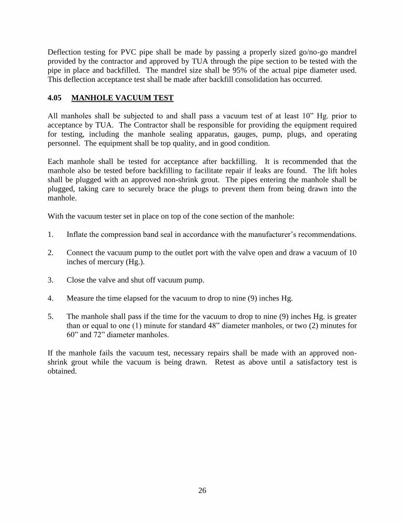
Deflection testing for PVC pipe shall be made by passing a properly sized go/no-go mandrel
provided by the contractor and approved by TUA through the pipe section to be tested with the
pipe in place and backfilled. The mandrel size shall be 95% of the actual pipe diameter used.
This deflection acceptance test shall be made after backfill consolidation has occurred.
4.05 MANHOLE VACUUM TEST
All manholes shall be subjected to and shall pass a vacuum test of at least 10” Hg. prior to
acceptance by TUA. The Contractor shall be responsible for providing the equipment required
for testing, including the manhole sealing apparatus, gauges, pump, plugs, and operating
personnel. The equipment shall be top quality, and in good condition.
Each manhole shall be tested for acceptance after backfilling. It is recommended that the
manhole also be tested before backfilling to facilitate repair if leaks are found. The lift holes
shall be plugged with an approved non-shrink grout. The pipes entering the manhole shall be
plugged, taking care to securely brace the plugs to prevent them from being drawn into the
manhole.
With the vacuum tester set in place on top of the cone section of the manhole:
1. Inflate the compression band seal in accordance with the manufacturer’s recommendations.
2. Connect the vacuum pump to the outlet port with the valve open and draw a vacuum of 10
inches of mercury (Hg.).
3. Close the valve and shut off vacuum pump.
4. Measure the time elapsed for the vacuum to drop to nine (9) inches Hg.
5. The manhole shall pass if the time for the vacuum to drop to nine (9) inches Hg. is greater
than or equal to one (1) minute for standard 48” diameter manholes, or two (2) minutes for
60” and 72” diameter manholes.
If the manhole fails the vacuum test, necessary repairs shall be made with an approved non-
shrink grout while the vacuum is being drawn. Retest as above until a satisfactory test is
obtained.

27
TULLAHOMA UTILITIES AUTHORITY
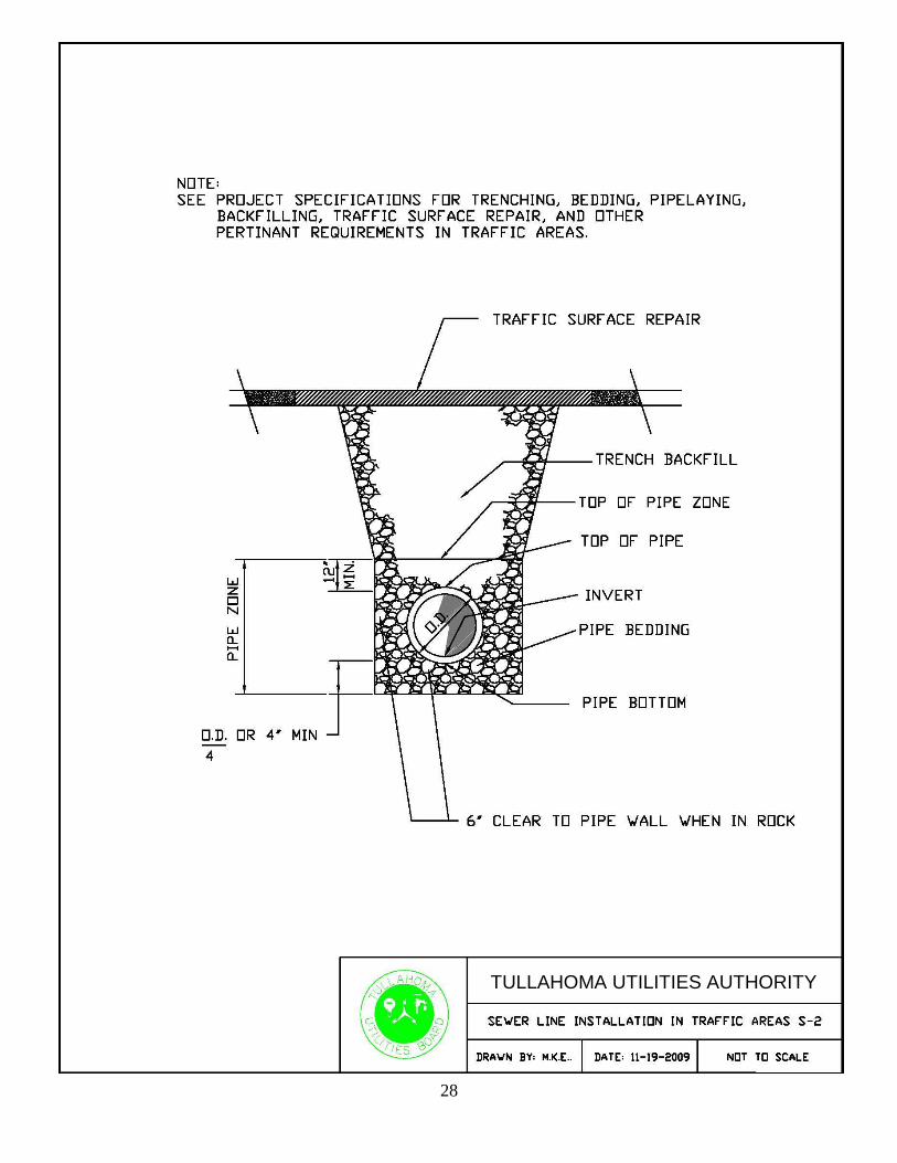
28
TULLAHOMA UTILITIES AUTHORITY
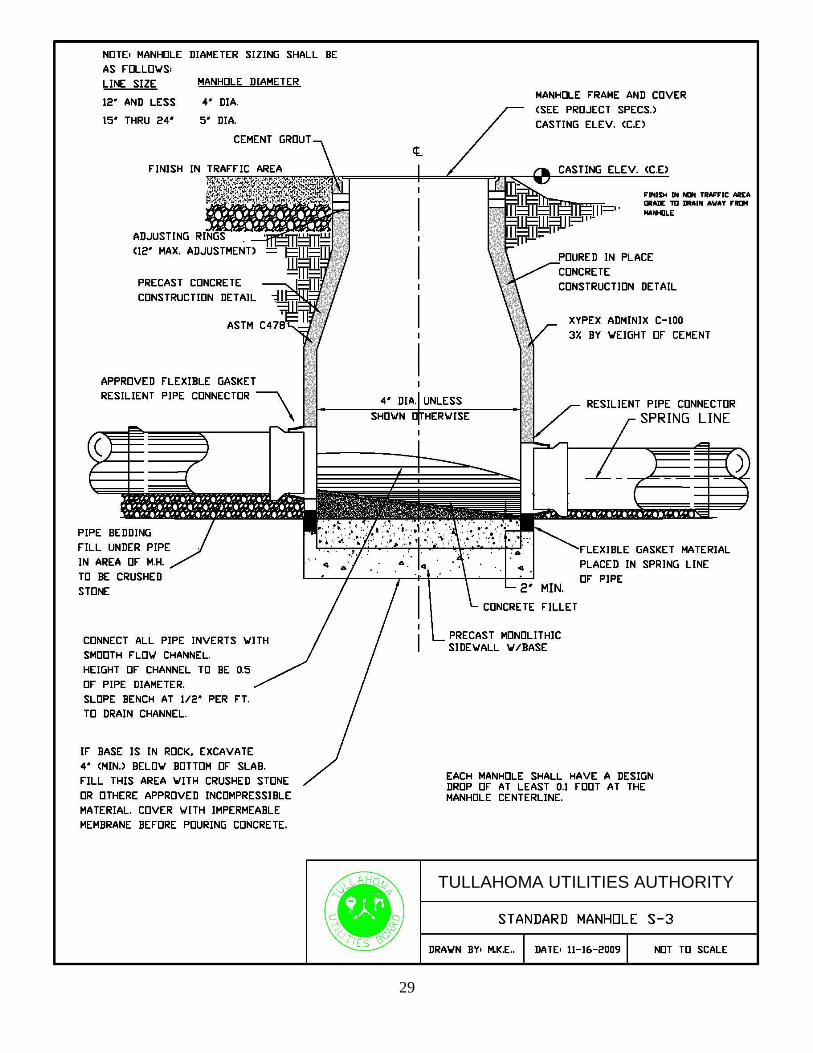
29
TULLAHOMA UTILITIES AUTHORITY TULLAHOMA UTILITIES AUTHORITY
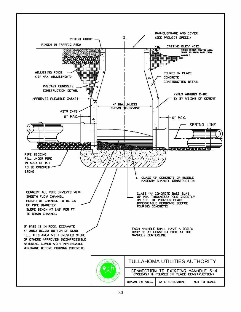
30
TULLAHOMA UTILITIES AUTHORITY
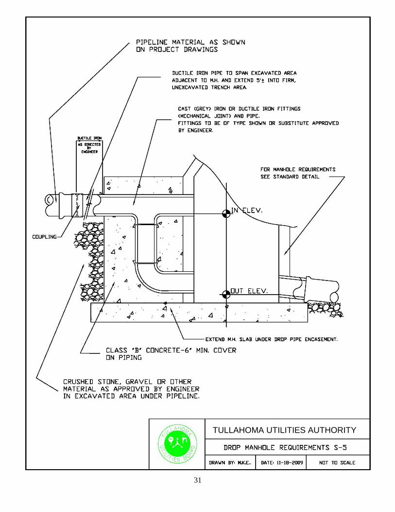
31
TULLAHOMA UTILITIES AUTHORITY
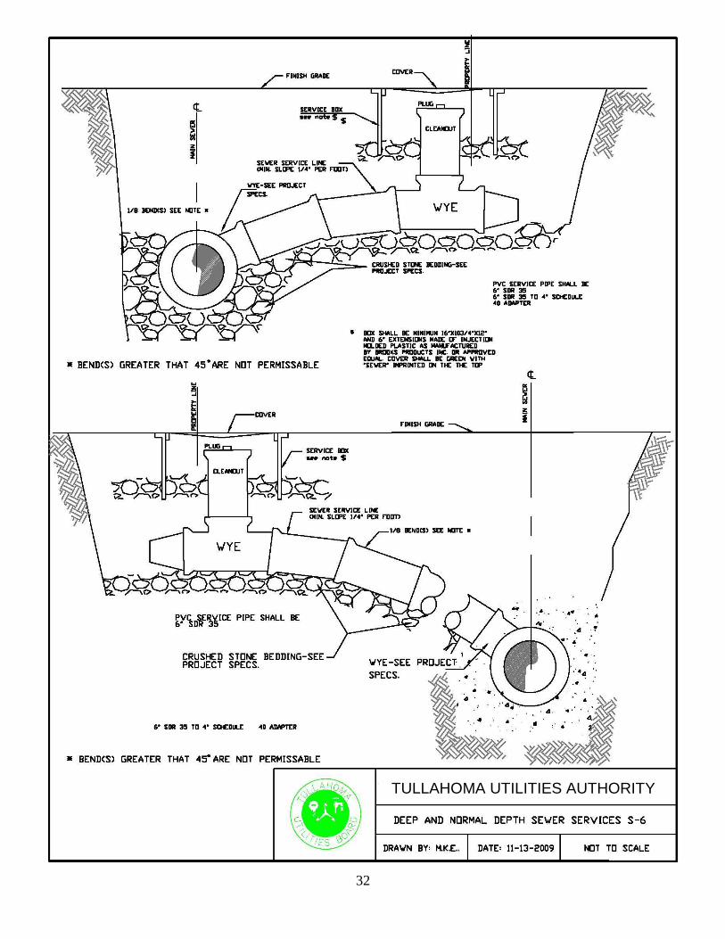
32
TULLAHOMA UTILITIES AUTHORITY
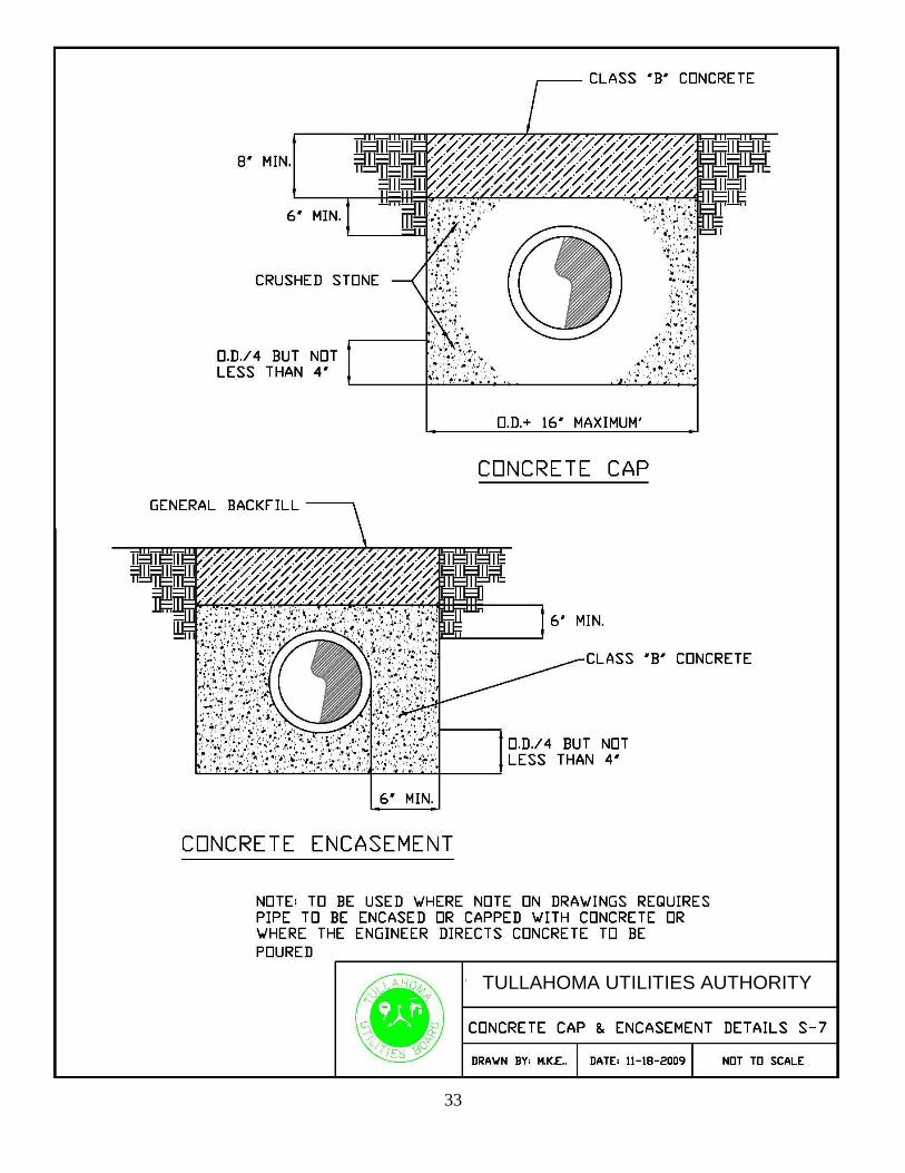
33
TULLAHOMA UTILITIES AUTHORITY