design, construction & simulation aspects of offshore …
TRANSCRIPT

.
DONG gas pipeline 187 Km, Denmark, Contractor: Per Aarsleff A/s
DESIGN, CONSTRUCTION & SIMULATION ASPECTS OF OFFSHORE AND ONSHORE CRUDE OIL PIPELINE
SYSTEM
-RAVI SHANKARDate: June 2006.

1. CONTENTS
PART – A Reservoir basics
1 Reservoir engineering2 Recovery methods – water injection
PART – B Pipeline engineering & construction
3 Design data4 Mechanical works inspection5 Design & construction6 Pigging operations7 Commissioning8 Materials & corrosion9 Computational fluid dynamics10 Risk, safety and hazard

hA
Area, Top chalk
-6500
-6400
-6300
-6200
-6100
-6000
-59000 5 10 15 20 25
Area, Km*2
m
Series1Linear (Series1)
1. RESERVOIR ENGINEERING
Total oil reserves, N or
STOIIP = 1.07E+08 barrels

2. WATER INJECTION
- Water discharge at offshore
- Water injection system, design for 10 years

2. WATER DISPOSAL SYSTEM

2. WATER DISPOSAL SYSTEM

2. WATER INJECTION SYSTEM
Water injection Vs Production
-50000000
50000001000000015000000200000002500000030000000
0 2 4 6 8 10 12
Year
Flow
[bar
rels
Series1
Series2
CALCULATED
Total oil reserves, N or
STOIIP = 1.07E+08 barrels
Production rate = 73000BPD
> 20 years
ASSUMED
Total oil reserves, N or
STOIIP = 1.50E+06 barrels
Production rate = 73000BPD
= 10 years
Boi = 1.3
Bo = 1.33

PIPELINE ENGINEERING
PART - B
DESIGN & CONSTRUCTION
- Project management
- Mechanical configuration
- Material Selection
- Pigging operations
- Hydrostatic testing
- Cathodic protection
- Corrosion defect risk
assessment
- Control system
SIMULATION
- Flow configuration
- K7O using PRO II
- CFD, Heat conduction TDMA, Central differencing method
- Safety and hazard
- Pipeline toolbox 2006

E&CContractor
Per Aarsleff A/S
Pipe SupplierManufacturer
Sub-ContractorConsultant
ClientDONG
USERMaersk
PIPE
BOOK
ConsultantBureau
B
A
PROJECT MANAGEMENT
EXAMPLE:
User: Maersk Olie og GasClient: DONG, owner of pipelineConsultant: Aalborg UniversityMain contractor: Ex: Per Aarsleff A/s

PIPELINE ENGINEERING
PART - B
DESIGN & CONSTRUCTION
- Project management
- Mechanical configuration
- Material Selection
- Pigging operations
- Hydrostatic testing
- Cathodic protection
- Corrosion defect risk
assessment
- Control system
SIMULATION
- Flow configuration
- K7O using PRO II
- CFD, Heat conduction TDMA, Central differencing method
- Safety and hazard
- Pipeline toolbox 2006

MECHANICAL CONFIGURATION
D/t ratio of 16in., API X60 Pipeline
01020304050607080
0.00 5.00 10.00 15.00 20.00 25.00
Wall thickness, mm
D /
t
5.56
6.35
7.14
7.92
8.74
9.53
11.13
12.70
19.05
F = 0.72

MECHANICAL CONFIGURATION- Pipeline alignment sheet

PIPELINE ENGINEERING
PART - B
DESIGN & CONSTRUCTION
- Project management
- Mechanical configuration
- Material Selection
- Pigging operations
- Hydrostatic testing
- Cathodic protection
- Corrosion defect risk
assessment
- Control system
SIMULATION
- Flow configuration
- K7O using PRO II
- CFD, Heat conduction TDMA, Central differencing method
- Safety and hazard
- Pipeline toolbox 2006

FLOW CONFIGURATION


PIPELINE ENGINEERING
PART - B
DESIGN & CONSTRUCTION
- Project management
- Mechanical configuration
- Material Selection
- Pigging operations
- Hydrostatic testing
- Cathodic protection
- Corrosion defect risk
assessment
- Control system
SIMULATION
- Flow configuration
- K7O using PRO II
- CFD, Heat conduction TDMA, Central differencing method
- Safety and hazard
- Pipeline toolbox 2006

- Money,- Market availability,- Life,- Operating conditions, pressure, temperature and flow,- Weight,- Environment, air, water, earth and soil.
MATERIALS
Hardness Test
0100200300400500600700800
0 1 2 3 4 5
1-Hardness; 2-Tempered; 3-Untreated; 4-Corss section
Vick
er re
adin
Series1
Hardness of a martensitic steel
0100200300400500600700800900
0 0.5 1 1.5
% of carbon
Vic
ker's
Har
dne
Series1
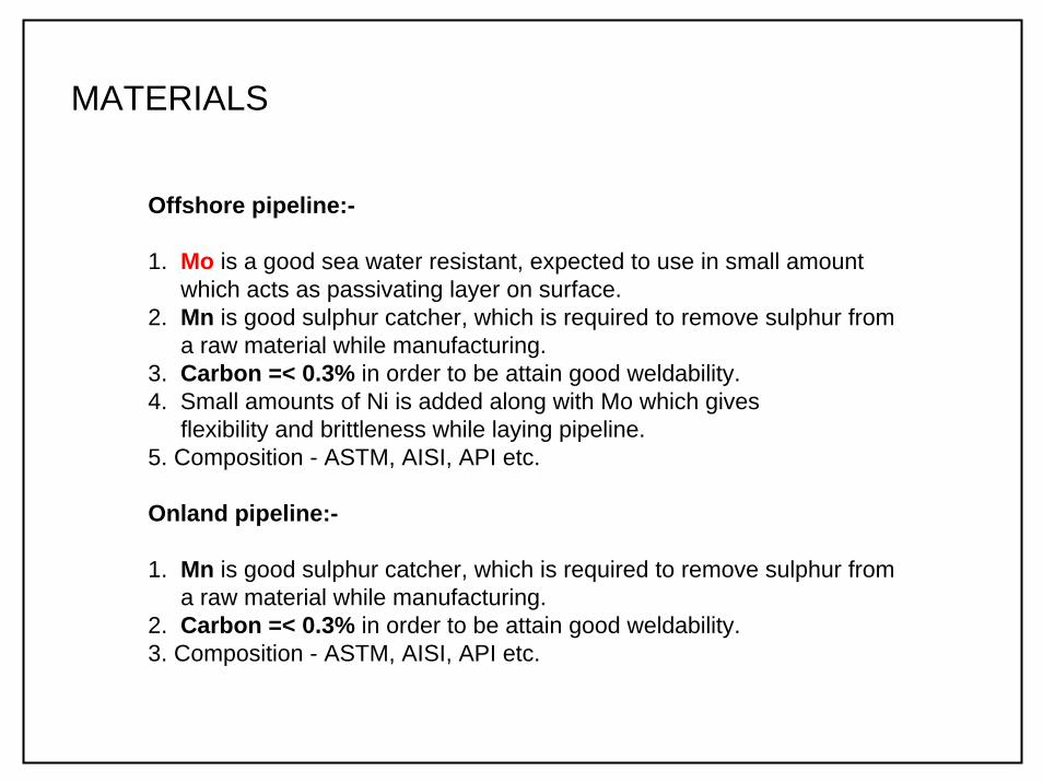
Offshore pipeline:-
1. Mo is a good sea water resistant, expected to use in small amount which acts as passivating layer on surface.
2. Mn is good sulphur catcher, which is required to remove sulphur from a raw material while manufacturing.
3. Carbon =< 0.3% in order to be attain good weldability.4. Small amounts of Ni is added along with Mo which gives
flexibility and brittleness while laying pipeline.5. Composition - ASTM, AISI, API etc.
Onland pipeline:-
1. Mn is good sulphur catcher, which is required to remove sulphur from a raw material while manufacturing.
2. Carbon =< 0.3% in order to be attain good weldability.3. Composition - ASTM, AISI, API etc.
MATERIALS

PIPELINE ENGINEERING
PART - B
DESIGN & CONSTRUCTION
- Project management
- Mechanical configuration
- Material Selection
- Pigging operations
- Hydrostatic testing
- Cathodic protection
- Corrosion defect risk
assessment
- Control system
SIMULATION
- Flow configuration
- K7O using PRO II
- CFD, Heat conductionTDMA, Central differencing method
- Safety and hazard
- Pipeline toolbox 2006

Heat conduction using CFD
- 1 dimensional heat transfer
- Steady state heat conduction
- Heat conduction from pipe-soil-environment
- Linearising the terms

Heat conduction using CFD
TDMA method using MS excel sheet:
Heat transfer by conduction
020406080
100120140160180200
0 2 4 6 8 10 12Distance, Xi
Tem
pera
ture
,
Series1

Heat conduction using CFD
Central differencing method using Matlab:
1 2 3 4 5
W P E
wxδ exδ
xδX = 0
X = 5
TA
TB
TW
TE
STaTaTa wwEEPP ++=
W
W
E
EP x
Kx
Kaδδ
+=E
EE x
Ka
δ=
W
WW x
Ka
δ=
.
wEP aaa += xSΔ Ppu TSS +and b = =

PIPELINE ENGINEERING
PART - B
DESIGN & CONSTRUCTION
- Project management
- Mechanical configuration
- Material Selection
- Pigging operations
- Hydrostatic testing
- Cathodic protection
- Corrosion defect risk
assessment
- Control system
SIMULATION
- Flow configuration
- K7O using PRO II
- CFD, Heat conduction
using MatlabTDMA, Central differencing method
- Safety and hazard
- Pipeline toolbox 2006

PIGGING OPERATIONS

PIGGING OPERATIONS

PIGGING OPERATIONS

PIGGING OPERATIONS

PIPELINE ENGINEERING
PART - B
DESIGN & CONSTRUCTION
- Project management
- Mechanical configuration
- Material Selection
- Pigging operations
- Hydrostatic testing
- Cathodic protection
- Corrosion defect risk
assessment
- Control system
SIMULATION
- Flow configuration
- K7O using PRO II
- CFD, Heat conduction
using MatlabTDMA, Central differencing method
- Safety and hazard
- Pipeline toolbox 2006

HYDROSTATIC TESTING

- Cleaning
- Gauging
- Filling
- Pressurising
- Evaluation
- Dewatering
- Swabbing
- Drying
- Commissioning
HYDROSTATIC TESTING
Volume required to fill section, V = 11623.52 m3
Pressure change due to temperature change, = 0.316 bar
Difference between initial and final adjusted pressure = - 0.116 bar
Pδ

PIPELINE ENGINEERING
PART - B
DESIGN & CONSTRUCTION
- Project management
- Mechanical configuration
- Material Selection
- Pigging operations
- Hydrostatic testing
- Cathodic protection
- Corrosion defect risk
assessment
- Control system
SIMULATION
- Flow configuration
- K7O using PRO II
- CFD, Heat conduction
using MatlabTDMA, Central differencing method
- Safety and hazard

CATHODIC PROTECTION
Net mass of anodes
05000
1000015000
20000250003000035000
0 20 40 60 80 100 120 140 160
Chainage, Km
Mas
s of
ano
d
Series1Series2Impressed current system:
Mass of anodes = 120Kg at K75 and K125 locations
Galvanic system:Mass of anodes = 30000 Kg/Km at all pipe jointing locations

PIPELINE ENGINEERING
PART - B
DESIGN & CONSTRUCTION
- Project management
- Mechanical configuration
- Material Selection
- Pigging operations
- Hydrostatic testing
- Cathodic protection
- Corrosion defect risk
assessment
- Control system
SIMULATION
- Flow configuration
- K7O using PRO II
- CFD, Heat conduction
using MatlabTDMA, Central differencing method
- Safety and hazard

Corrosion Defect Assessment - PIPELINE TOOLBOX 2006, RSTRENG
PIT measurement
0
50
100
150
200
250
300
0 1 2 3 4 5 6 7Total pit length, in
Pit
dept
h, m
PIT measurement

PIPELINE ENGINEERING
PART - B
DESIGN & CONSTRUCTION
- Project management
- Mechanical configuration
- Material Selection
- Pigging operations
- Hydrostatic testing
- Cathodic protection
- Corrosion defect risk
assessment
- Control system
SIMULATION
- Flow configuration
- K7O using PRO II
- CFD, Heat conduction
using MatlabTDMA, Central differencing method
- Safety and hazard

CONTROL SYSTEM- GAS PIPELINE
Pressure limiting system
A Operating pressure limiting system
B Safety pressure limiting system
C Thermal pressure safety relief system
1.
2. Compressor piping, SMYS = 3 x MOP
3. Mainline pressure NOT to exceed 10% of MOP = 60.5 bar
OR NOT to exceed 75% of SMYS4. Compressor piping pressure NOT to exceed 10% of MOP = 82.5 bar

CONTROL SYSTEM- GAS PIPELINE

PIPELINE ENGINEERING
PART - B
DESIGN & CONSTRUCTION
- Project management
- Mechanical configuration
- Material Selection
- Pigging operations
- Hydrostatic testing
- Cathodic protection
- Corrosion defect risk
assessment
- Control system
SIMULATION
- Flow configuration
- K7O using PRO II
- CFD, Heat conduction
using MatlabTDMA, Central differencing method
- Safety and hazard

SAFETY AND HAZARD
• Safety during hydrostatic testing
2. Chemical reaction concepts
3. Turbulance generation due to flame acceleration
4. Explosion in a gas pipeline
25C Temperature
Fuel concentration
0%
100%Vaporpressure
Flash point
AutoIgnitionregion
UFL
LFL
AIT
Flammable mixture

Ignition
Transition to detonation
DetonationSAFETY AND HAZARD
16 inch
Run up distance
Run up distance = 33 m.
Flame velocity, m/s.
Flame velocity = 30 m/s
Time taken to detonate the 16in pipeline carrying propane = 1.1 sec.

END OF PRESENTATIONTHANK YOU