design-build request for proposal for sr 15/600 (us … build/e5r71... · interchange (spui) at sr...
TRANSCRIPT

Florida Department of Transportation
District V
DESIGN-BUILD REQUEST FOR PROPOSAL
for SR 15/600 (US 17/92) Interchange at SR 436, Seminole County
Financial Projects Number(s):404418-1-52-01 Federal Aid Project Number(s): 3521-006-P
Contract Number: E-5R71
Draft Request for Proposal SR 15/600 (US 17/92) Interchange at SR 436 FM: 404418-1-52-01 February 18, 2013
Page i
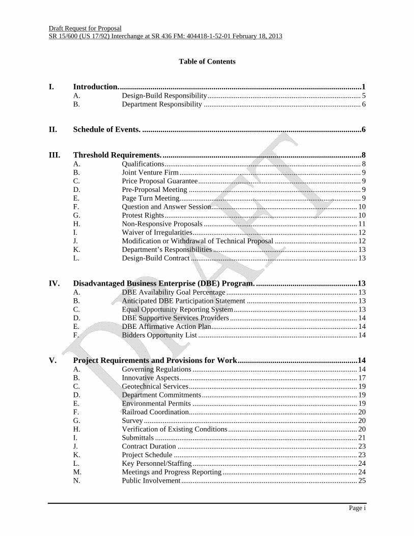
Table of Contents
I. Introduction. .......................................................................................................................1 A. Design-Build Responsibility .................................................................................. 5 B. Department Responsibility .................................................................................... 6
II. Schedule of Events. ............................................................................................................6
III. Threshold Requirements. ..................................................................................................8 A. Qualifications ......................................................................................................... 8 B. Joint Venture Firm ................................................................................................. 9 C. Price Proposal Guarantee ....................................................................................... 9 D. Pre-Proposal Meeting ............................................................................................ 9 E. Page Turn Meeting ................................................................................................. 9 F. Question and Answer Session .............................................................................. 10 G. Protest Rights ....................................................................................................... 10 H. Non-Responsive Proposals .................................................................................. 11 I. Waiver of Irregularities ........................................................................................ 12 J. Modification or Withdrawal of Technical Proposal ............................................ 12 K. Department’s Responsibilities ............................................................................. 13 L. Design-Build Contract ......................................................................................... 13
IV. Disadvantaged Business Enterprise (DBE) Program. ..................................................13 A. DBE Availability Goal Percentage ...................................................................... 13 B. Anticipated DBE Participation Statement ........................................................... 13 C. Equal Opportunity Reporting System .................................................................. 13 D. DBE Supportive Services Providers .................................................................... 14 E. DBE Affirmative Action Plan .............................................................................. 14 F. Bidders Opportunity List ..................................................................................... 14
V. Project Requirements and Provisions for Work ...........................................................14 A. Governing Regulations ........................................................................................ 14 B. Innovative Aspects ............................................................................................... 17 C. Geotechnical Services .......................................................................................... 19 D. Department Commitments ................................................................................... 19 E. Environmental Permits ........................................................................................ 19 F. Railroad Coordination .......................................................................................... 20 G. Survey .................................................................................................................. 20 H. Verification of Existing Conditions ..................................................................... 20 I. Submittals ............................................................................................................ 21 J. Contract Duration ................................................................................................ 23 K. Project Schedule .................................................................................................. 23 L. Key Personnel/Staffing ........................................................................................ 24 M. Meetings and Progress Reporting ........................................................................ 24 N. Public Involvement .............................................................................................. 25

Draft Request for Proposal SR 15/600 (US 17/92) Interchange at SR 436 FM: 404418-1-52-01 February 18, 2013
Page ii
O. Quality Management Plan (QMP) ....................................................................... 26 P. Liaison Office ...................................................................................................... 27 Q. Engineers Field Office ......................................................................................... 27 R. Schedule of Values .............................................................................................. 28 S. Computer Automation ......................................................................................... 28 T. Construction Engineering and Inspection ............................................................ 28 U. Testing ................................................................................................................. 28 V. Value Added ........................................................................................................ 29 W. Adjoining Construction Projects .......................................................................... 29 X. Use of Department Owned Right of Way ............................................................ 29 Y. Design Issue Escalation ....................................................................................... 29 Z. Construction Clarification, Conflict Resolution, and Issue Escalation ................ 30
VI. Design and Construction Criteria. .................................................................................31 A. General ................................................................................................................. 31 B. Geotechnical Services .......................................................................................... 31 C. Utility Coordination ............................................................................................. 34 D. Roadway Plans ..................................................................................................... 35 E. Geometric ............................................................................................................ 37 F. Design Documentation, Computations and Quantities ........................................ 38 G. Structure Plans ..................................................................................................... 38 H. Specifications ....................................................................................................... 39 I. Shop Drawings ..................................................................................................... 40 J. Sequence of Construction .................................................................................... 40 K. Stormwater Pollution Prevention Plans (SWPPP) ............................................... 41 L. Temporary Traffic Control Plan .......................................................................... 41 M. Environmental Services/Permits/Mitigation ........................................................ 43 N. Signing and Pavement Marking Plans ................................................................. 44 O. Signalization Plans ............................................................................................... 45 P. Access Management Plan .................................................................................... 48 Q. Lighting Plans ...................................................................................................... 48 R. ITS ....................................................................................................................... 48 S. Utilities ................................................................................................................ 52 T. Aesthetics and Landscape .................................................................................... 52
VII. Technical Proposal Requirements. .................................................................................54 A. General ................................................................................................................. 54 B. Submittal Requirements ....................................................................................... 54 C. Evaluation Criteria ............................................................................................... 57 D. Final Selection Formula ....................................................................................... 58 E. Final Selection Process ........................................................................................ 58 F. Stipend Awards .................................................................................................... 59
VIII. Bid Proposal Requirements. ...........................................................................................59 A. Bid Price Proposal ............................................................................................... 59

Draft Request for Proposal SR 15/600 (US 17/92) Interchange at SR 436 FM: 404418-1-52-01 February 18, 2013
Page iii
ATTACHMENTS The Attachments listed below are hereby incorporated into and made a part of this Request for Proposal (RFP) as though fully set forth herein.
Project Advertisement Division I Design-Build Specifications Permits Typical Section Package Pavement Design Geotechnical Services Requirements/Specifications
Contractor Quality Control General Requirements (SP1050813DB) Structures Foundations (SP4550000DB)
Value Added Specifications Section 475, Value Added Bridge Component Section 645 and 611, Value Added Signal Installation Section 725, Value Added Highway Lighting System
Design Variations Right-of-Way Commitments Right-of-Way Maps ITS Damage Recovery Specifications Seminole County Signal Standards UWHC (Lump Sum Agreement with City of Casselberry) City of Casselberry Utility Plans

Draft Request for Proposal SR 15/600 (US 17/92) Interchange at SR 436 FM: 404418-1-52-01 February 18, 2013
Page iv
REFERENCE DOCUMENTS The following documents are being provided with this RFP. Except as specifically set forth in the body of this RFP, these documents are being provided for reference and general information only. They are not being incorporated into and are not being made part of the RFP, the contract documents or any other document that is connected or related to this Project except as otherwise specifically stated herein. No information contained in these documents shall be construed as a representation of any field condition or any statement of facts upon which the Design-Build Firm can rely upon in performance of this contract. All information contained in these reference documents must be verified by a proper factual investigation. The bidder agrees that by accepting copies of the documents, any and all claims for damages, time or any other impacts based on the documents are expressly waived.
SR 15/600 (US 17/92) at SR 436 Interchange Concept Plans (Includes all Component Plan sets) Existing Plans (City of Casselberry Streetscape Plans, Fern Park Plaza Parking Lot Modifications, & Lowes Fern Park Plans) Wal-Mart Supercenter Plans SR 15/600 (US 17/92) Interchange at SR 436 Microstation DGN Files Bridge Development Report (BDR) Geotechnical Information Memorandum of Understanding (MOU) Locally Funded Agreements (LFA) PD&E Study Level II Preliminary Contamination Assessment Roadway Design Notebook Drainage Report Lighting Calculations Structural Calculations Utility Backup Information

Draft Request for Proposal SR 15/600 (US 17/92) Interchange at SR 436 FM: 404418-1-52-01 February 18, 2013
Version 2012-02a dated: 11/05/2012 Page 1 of 60
I. Introduction. The Florida Department of Transportation (Department) has issued this Request for Proposal (RFP) to solicit competitive bids and proposals from Proposers for the design and construction of a single point urban interchange (SPUI) at SR 15/600 (US 17/92) and SR 436 in City of Casselberry, Seminole County, Florida. Description of Work For clarity in communication, the following project/work description is broken down as follows:
Overview of the roadway construction to be completed Drainage and Environmental Traffic Control Signing and Pavement Markings Signals Lighting Utilities ITS Aesthetics and Landscaping
Overview of the roadway construction to be completed The intersection of SR 15/600 (US 17/92) at SR 436 is located in the southwest quadrant of Seminole County, Florida. The scope of work for this project includes all investigation, design, permitting, coordination, and construction activities necessary for the construction of a single point urban interchange (SPUI) at SR 15/600 (US 17/92) and SR 436. The interchange will elevate 4 lanes of SR 15/600 (US 17/92) over SR 436. The project is approximately 0.65 miles in length. The project limits along SR 15/600 are from station 419+00 (Prairie Lake Drive) to station 465+30 (about 300 feet north of Sunnytown Road). Approximately the first 450 feet and the last 350 feet consist of milling and resurfacing and minor construction activities such as signage and lighting. Along SR 436, the project limits extend from station 417+57 (Oxford Road) to station 429+00 (immediately west of SR 15/600). The project limits shall be extended, beyond the original concept plan limits as stated above, to the west of SR 15/600 on SR 436 and shall include milling and resurfacing and signing and pavement markings (approximate station limits 429+00 to 437+20). The milling and resurfacing and signing and pavement markings will be extended to the east of SR 15/600 on SR 436 just past Oxford Road to the Point of Curvature (PC) of the return (approximate station limits 412+15 to 417+45.47). The construction limits on Oxford Road to include the PC of the returns. The typical section along SR 15/600 (US 17/92), north and south of the SR 436 intersection, includes three 12-ft wide through lanes in each direction separated by a 14-ft wide median. A 4-ft wide bicycle lane, 2-ft wide curb and gutter, and an 8-ft concrete sidewalk is required on each side. The SR 15/600 mainline bridges (Bridge Nos. 770091 & 770092) over SR 436 will include two 12-ft through lanes, 6-ft inside shoulder and 10-ft outside shoulder in each direction. The northbound and southbound through lanes will be separated by concrete traffic barriers (see Typical Section Package in the Attachments). The northbound exit ramp cross section will include two 12-ft wide left turn lanes, one 12-ft wide through lane, one 12-ft wide right-turn lane, a 4-ft wide bicycle lane, 2-ft wide curb and gutter, a 12-ft wide concrete sidewalk at ground level intersection with SR 436, and a dedicated U-Turn lane under the bridge. The southbound exit ramp cross section will include three 12-ft wide left-turn lanes, one 12-ft wide through lane, one 12-ft wide right-turn lane, a 4-ft wide bicycle lane, 2-ft wide curb and gutter, an 8-ft concrete sidewalk at ground level intersection with SR 436, and a dedicated U-Turn lane under the bridge. All bicycle keyhole lanes to be 5’ wide.

Draft Request for Proposal SR 15/600 (US 17/92) Interchange at SR 436 FM: 404418-1-52-01 February 18, 2013
Version 2012-02a dated: 11/05/2012 Page 2 of 60
The Department, under a separate contract, has produced concept plans. These plans will be referred to as concept plans. The concept plans are included in Reference Documents of this RFP and are supplied to the Design-Build Firm for information purposes. The Department has developed an approved typical section package which can be found in the Attachments of this RFP. All elements shown on the typical section package are considered requirements for this project. During the development of the concept plans an approved pavement design was developed. This pavement design is the minimum pavement design to be constructed for this project. The pavement design can be found in the Attachments portion of this RFP. The Department has acquired all necessary right-of-way for the project, including limited access right of way, as shown in the concept plans. Driveway connections shall remain as shown in the concept plans. The Design-Build Firm shall comply with all right-of-way commitments made by the Department. These are included as an attachment to this RFP. It is the Department’s intent that all Project construction activities be conducted utilizing the existing horizontal alignment within the existing right-of-way. The Design-Build Firm may submit a Technical Proposal that requires the acquisition of additional right-of-way. Any Technical Proposal that requires the acquisition of additional right-of-way will not extend the contract duration as set forth in the existing Request for Proposal under any circumstances. The Department will have sole authority to determine whether the acquisition of additional right-of-way on the Project is in the Department’s best interest, and the Department reserves the right to reject the acquisition of additional right-of-way. If a Design-Build Firm intends to submit a Technical Proposal that requires the acquisition of additional right-of-way, the Design-Build Firm shall discuss such a proposal with the Department as part of the Question & Answer process or as part of the Alternative Technical Concept process, as applicable. If a Design-Build Firm submits a Technical Proposal that requires the acquisition of additional right-of-way and the Design-Build Firm fails to discuss such a proposal with the Department as part of the Question & Answer process or as part of the Alternative Technical Concept process, then the Department will not consider such aspects of the Proposal during the Evaluation process. If the Design-Build Firm’s Technical Proposal requires additional right-of-way, and the Department concurs such acquisition is in the best interest of the project the additional right-of-way will be required to be directly acquired by the Department in the following manner. The Design-Build Firm shall submit, along with the Technical Proposal, certified sketches and legal descriptions including area in square feet of any proposed additional right of way parcels. The additional right-of-way will be acquired by the Department in accordance with all applicable state and federal laws, specifically including but not limited to the Uniform Relocation Assistance and Real Property Acquisition Policies for Federal and Federally Assisted Programs (42 USC Chapter 61) and its implementing regulations. All costs concerning the acquisition of additional right-of-way will be borne solely by the Design-Build Firm. The Department will have sole discretion with respect to the entire acquisition process of the additional right-of-way. If the Design-Build Firm’s Technical Proposal requires additional right-of-way, the acquisition of any such right-of-way shall be at no cost to the Department, and all costs associated with securing and making ready for use such right-of-way for the Project shall be borne solely by the Design-Build Firm as a part of the Design-Build Firm’s Lump Sum Price Bid. The Department will not advance any funds for any such right-of-way acquisition and the Design-Build Firm shall bear all risk of delays in the acquisition of the additional property, regardless of cause or source. The Department will provide to the successful Design-Build Firm an estimate of all costs related to the
Draft Request for Proposal SR 15/600 (US 17/92) Interchange at SR 436 FM: 404418-1-52-01 February 18, 2013
Version 2012-02a dated: 11/05/2012 Page 3 of 60
acquisition and use of the additional right of way for the project. At the time the Design-Build Firm returns the executed contract to the Department, the Design-Build Firm will provide the Department funds equal to the amount of the Department’s estimate along with a Letter of Credit approved by the Department in an amount equal to 100% of the Department’s estimate. If additional funds beyond the Department’s estimate are anticipated, the Design-Build Firm shall be solely responsible for all such costs and provide the same to the Department upon ten (10) days written notice from the Department. The Letter of Credit is for the purpose of securing the obligations of the Design-Build Firm with respect to the acquisition and use of additional right of way. The Letter of Credit will be released upon the Department’s determination that all costs related to the acquisition of and making ready for use of the additional right of way have been satisfied. Any remaining funds provided will be returned to the Design-Build Firm. Any additional right-of-way must be acquired prior to the commencement of any construction on the Project. The Design-Build Firm waives any and all rights or claims for information, compensation, or reimbursement of expenses with respect to the Design-Build Firm’s payment to the Department for costs associated with the acquisition of the additional right-of-way. The additional right-of-way cannot be used for any construction activity or other purpose until the Department has issued an applicable parcel clear letter or a Right-of-Way Certification for Construction. If the Department’s attempt to acquire the additional right-of-way is unsuccessful, then the Design-Build Firm shall provide a design of the Project within existing right-of-way and be required to complete the Project solely for the Lump Sum Price Bid, with no further monetary or time adjustments arising there from. Under no circumstances will the Department be liable for any increase in either time or money impacts the Design-Build Firm suffers due to the Design-Build Firm’s proposed acquisition of additional right-of-way, whether or not the acquisition is successful. The concept plans do not include any topographic survey of the Lowes located on SR 15/600 or the improvements to the parking lot and drainage systems of the Shoppes at Fern Park on SR 436. The proposed Wal-Mart Supercenter is shown as an existing condition in the concept plans but construction has yet to begin. The additional areas of milling and resurfacing and the location of the additional mast arms at Oxford Road (will be discussed further in the signal portion below) were not surveyed during the development of the concept plans. The Design-Build Firm is required to provide a power source to supply electricity to all electrically powered devices within the project limits. This project will require approximately seven (7) separate meters. The Design-Build Firm will coordinate with FDOT, Seminole County and the City of Casselberry regarding the number of meters. Drainage and Environmental This project has received a construction permit from SJRWMD; (General) Permit No. 40-117-114871-1, issued July 22, 2008, and extended until July 22, 2013. A copy of this permit and the extension can be found in the Attachments of this RFP. A Level II Preliminary Contamination Assessment (PCA) was performed during the development of the concept plans and can be found in Reference Documents. Traffic Control One potential example of construction phasing is presented in the Concept Traffic Control Plans (TCP), but it is at the discretion of the Design-Build Firm how the TCP will be executed and phased. The concept TCP plans can be found in the Roadway Concept plans in the Reference Documents section of

Draft Request for Proposal SR 15/600 (US 17/92) Interchange at SR 436 FM: 404418-1-52-01 February 18, 2013
Version 2012-02a dated: 11/05/2012 Page 4 of 60
this RFP. Signing and Pavement Markings Signing and Pavement Marking (SAPM) concept plans were developed during the development of the Roadway concept plans. The project limits for SAPM are SR 15/600 Sta. 419+00 to Sta. 465+30 and SR 436 Sta. 412+15 to Sta. 437+20. The SAPM concept plans can be found in the Reference Documents section of this RFP. Signals The City of Casselberry and FDOT entered into a Locally Funding Agreement (LFA: 404418-1-52-01 LFA City of Casselberry – Mast Arms 11-15-12.pdf) to upgrade from FDOT’s standard mast arm assembly to a decorative mast arm assembly. The mast arm upgrades shall have a separate sequence number (404418-1-52-03) line item on the Bid Proposal. The cost of the upgrades from standard mast arms to decorative mast arms shall be shown separate from the remainder of the project as outlined in the Bid Proposal. The decorative mast arm assemblies shall match the concept signal plans which can be found in Reference Documents. Mast arms shall conform to the latest Seminole County Mast Arm Standards. These Standards can found on Seminole County Traffic Engineering’s web site. The link can be found in the Attachments portion of this RFP. Lighting The Design-Build Firm shall be responsible for the design and construction of a new roadway lighting system on SR 15/600 from Ridge Road (approximate station 401+20) to Normandy Road (approximate station 466+70) and on SR 436 from Oxford Road (approximate station 411+90) to Anchor Road (approximate station 443+00). The Design-Build Firm shall be responsible for the design and construction of bridge underdeck lighting. Bridge underdeck lighting concept plans are included in the Reference Documents section of this RFP. Utilities The location of the utilities, as shown in the concept plans, are approximate and based on the information furnished to the Engineer by the Utility Owner(s) and are shown as notice to the Design-Build Firm that underground and overhead utilities exist. It will be the responsibility of the Design Build firm to perform all utility coordination in accordance with this RFP and FDOT standards and criteria. The concept utility adjustment plans can be found in the concept plans in the Reference Documents. The Design-Build Firm shall perform all of the City of Casselberry’s water and sewer construction/ adjustment/relocation work (including permitting) as approved by the City of Casselberry and FDOT. The water and sewer plans are located in the Attachments of this RFP. Should the Design-Build Firm’s proposed design impact the City of Casselberry’s water and sewer plans requiring the plans to be redesigned, the Design-Build Firm shall redesign the water and sewer plans and coordinate with FDOT and the City of Casselberry for approval. Upon redesign, the Design-Build Firm shall become the EOR for the plans and the City of Casselberry’s specifications and also be responsible for the signed and sealed as-builts. ITS During construction the Design-Build Firm will be responsible for maintaining continuous operation of all existing ITS facilities and the design and construction of all new ITS systems throughout the project limits in accordance with the requirements outlined in this RFP. This includes any and all aerial and/or underground fiber optic cable, Automatic Vehicle Identification (AVI) readers, Arterial Dynamic Message Signs (ADMS), Closed Circuit Television (CCTV), Fiber Optic Network (FON) cable, pull boxes and other associated infrastructure owned and/or maintained by FDOT and Seminole County

Draft Request for Proposal SR 15/600 (US 17/92) Interchange at SR 436 FM: 404418-1-52-01 February 18, 2013
Version 2012-02a dated: 11/05/2012 Page 5 of 60
Traffic Engineering. All ITS equipment used on the project for repair, relocation and new construction shall meet the requirements of the maintaining agency, FDOT and Seminole County. Aesthetics and Landscaping The Design-Build Firm will design and construct the following landscape, hardscape, and aesthetic features as seen on the concept plans. The hardscape and aesthetic features include; four (4) Architectural pylons with “CASSELBERRY” at the bridge abutment corners, and concrete sidewalk with eighteen (18) inch colored bands spaced every twenty (20) feet on center. The concrete sidewalk bands shall be “brick” color (match color of existing sidewalk bands) and use “brick’ patterned concrete. The concrete sidewalk bands shall be placed at all proposed sidewalk locations within the project. A Finish Schedule has been provided in Section VI of this RFP. Should the Design-Build Firm decide to use a girder material other than steel, the aesthetics for the bridge will require coordination and approval from FDOT and the City of Casselberry. The following aesthetic/hardscape items as seen on the concept plans are not required as part of the project: beam fascias, thickened bottom panels on the MSE walls, and patterned/textured asphalt. The concept hardscape and aesthetic plans can be found in the concept landscaping plans in the reference documents of this RFP. The Design-Build Firm will design and construct landscaping and irrigation for this project. Landscaping shall be provided at each pond and throughout the project limits. All planted areas shall be irrigated and mulched. A plant list has been included in Section VI of this RFP. The concept landscaping plans can be found in the Reference Documents of this RFP. The City of Casselberry entered into a Locally Funded Agreement (LFA – 404418-1-52-03 Landscape and Aesthetics) with FDOT. The LFA includes irrigation, landscaping, hardscape, and aesthetics for this project. The irrigation and architectural panel upgrades with the City’s name shall have a separate sequence number (404418-52-02) line item on the Bid Proposal. The cost of the upgrades shall be shown separate from the remainder of the project as outlined in the Bid Proposal. The Design-Build Firm shall coordinate with the City of Casselberry and FDOT regarding all aesthetics, hardscape, and landscaping features during the design process.
A. Design-Build Responsibility The Design-Build Firm shall be responsible for survey, geotechnical investigation, design, acquisition of all permits not acquired by the Department, any and all information required to modify permits acquired by the Department, maintenance of traffic, demolition, and construction on or before the Project completion date indicated in the Proposal. The Design-Build Firm will coordinate all utility relocations. The Design-Build Firm shall be responsible for compliance with Design and Construction Criteria (Section VI) which sets forth requirements regarding survey, design, construction, and maintenance of traffic during construction, requirements relative to Project management, scheduling, and coordination with other agencies and entities such as state and local government, utilities and the public. The Design-Build Firm shall be responsible for reviewing the approved Environmental Document of the PD&E Study. The Design-Build Firm is responsible for coordinating with the District Environmental Office any engineering information related to Environmental Reevaluations. The Design-Build Firm will not be compensated for any additional costs or time associated with Reevaluation(s) resulting from proposed design changes.

Draft Request for Proposal SR 15/600 (US 17/92) Interchange at SR 436 FM: 404418-1-52-01 February 18, 2013
Version 2012-02a dated: 11/05/2012 Page 6 of 60
The Design-Build Firm may propose changes which differ from the approved Interchange Proposal Report (if applicable) and/or the Project Development & Environment (PD&E) Study. Proposed changes must be coordinated through the Department. If changes are proposed to the configuration, the Design-Build Firm shall be responsible for preparing the necessary analyses and documentation required to satisfy requirements to obtain approval of the Department and , if applicable, FHWA. The Design-Build Firm shall provide the required documentation for review and processing. Approved revisions to the configuration may also be required to be included in the Reevaluation of the National Environmental Policy Act (NEPA) document or State Environmental Impact Report (SEIR) Reevaluations, per Section M (Environmental Services/Permits/Mitigation) of the RFP. The Design-Build Firm will not be compensated for any additional costs or time resulting from proposed changes. The Design-Build Firm shall examine the Contract Documents and the site of the proposed work carefully before submitting a Proposal for the work contemplated and shall investigate the conditions to be encountered, as to the character, quality, and quantities of work to be performed and materials to be furnished and as to the requirements of all Contract Documents. Written notification of differing site conditions discovered during the design or construction phase of the Project will be given to the Department’s Project Manager. The Design-Build Firm shall examine boring data, where available, and make their own interpretation of the subsoil investigations and other preliminary data, and shall base their bid on their own opinion of the conditions likely to be encountered. The submission of a proposal is prima facie evidence that he Design-Build Firm has made an examination as described in this provision. The Design-Build Firm shall demonstrate good Project management practices while working on this Project. These include communication with the Department and others as necessary, management of time and resources, and documentation. It shall be the responsibility of the Design-Build Firm to survey any and all areas necessary to perform design and construct the project. The Design-Build Firm shall be responsible for the design and construction of a new roadway lighting system for the entire project limits including bridge underdeck lighting. It will be the responsibility of the Design-Build Firm to perform all utility coordination in accordance with this RFP and FDOT standards and criteria.
B. Department Responsibility The Department will provide contract administration, management services, construction engineering inspection services, environmental oversight, and quality acceptance reviews of all work associated with the development and preparation of the contract plans, permits, , and construction of the improvements. The Department will provide job specific information and/or functions as outlined in this document. In accordance with 23 CFR 636.109 of the FHWA, in a Federal Aid project, the Department shall have oversight, review, and approval of the permitting process. The Department will determine the environmental impacts and coordinate with the appropriate agencies during the preparation of NEPA or SEIR Reevaluations. For federal projects, the Department will coordinate and process Reevaluations with FHWA.
II. Schedule of Events.
Draft Request for Proposal SR 15/600 (US 17/92) Interchange at SR 436 FM: 404418-1-52-01 February 18, 2013
Version 2012-02a dated: 11/05/2012 Page 7 of 60
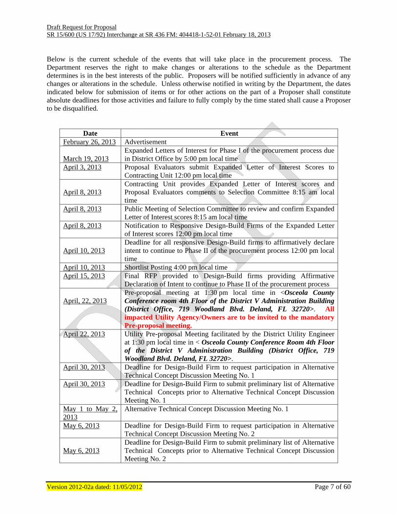
Below is the current schedule of the events that will take place in the procurement process. The Department reserves the right to make changes or alterations to the schedule as the Department determines is in the best interests of the public. Proposers will be notified sufficiently in advance of any changes or alterations in the schedule. Unless otherwise notified in writing by the Department, the dates indicated below for submission of items or for other actions on the part of a Proposer shall constitute absolute deadlines for those activities and failure to fully comply by the time stated shall cause a Proposer to be disqualified.
Date Event February 26, 2013 Advertisement March 19, 2013
Expanded Letters of Interest for Phase I of the procurement process due in District Office by 5:00 pm local time
April 3, 2013 Proposal Evaluators submit Expanded Letter of Interest Scores to Contracting Unit 12:00 pm local time
April 8, 2013
Contracting Unit provides Expanded Letter of Interest scores and Proposal Evaluators comments to Selection Committee 8:15 am local time
April 8, 2013
Public Meeting of Selection Committee to review and confirm Expanded Letter of Interest scores 8:15 am local time
April 8, 2013
Notification to Responsive Design-Build Firms of the Expanded Letter of Interest scores 12:00 pm local time
April 10, 2013
Deadline for all responsive Design-Build firms to affirmatively declare intent to continue to Phase II of the procurement process 12:00 pm local time
April 10, 2013 Shortlist Posting 4:00 pm local time April 15, 2013 Final RFP provided to Design-Build firms providing Affirmative
Declaration of Intent to continue to Phase II of the procurement process April, 22, 2013
Pre-proposal meeting at 1:30 pm local time in <Osceola County Conference room 4th Floor of the District V Administration Building (District Office, 719 Woodland Blvd. Deland, FL 32720>. All impacted Utility Agency/Owners are to be invited to the mandatory Pre-proposal meeting.
April 22, 2013 Utility Pre-proposal Meeting facilitated by the District Utility Engineer at 1:30 pm local time in < Osceola County Conference Room 4th Floor of the District V Administration Building (District Office, 719 Woodland Blvd. Deland, FL 32720>.
April 30, 2013 Deadline for Design-Build Firm to request participation in Alternative Technical Concept Discussion Meeting No. 1
April 30, 2013 Deadline for Design-Build Firm to submit preliminary list of Alternative Technical Concepts prior to Alternative Technical Concept Discussion Meeting No. 1
May 1 to May 2, 2013
Alternative Technical Concept Discussion Meeting No. 1
May 6, 2013 Deadline for Design-Build Firm to request participation in Alternative Technical Concept Discussion Meeting No. 2
May 6, 2013
Deadline for Design-Build Firm to submit preliminary list of Alternative Technical Concepts prior to Alternative Technical Concept Discussion Meeting No. 2
Draft Request for Proposal SR 15/600 (US 17/92) Interchange at SR 436 FM: 404418-1-52-01 February 18, 2013
Version 2012-02a dated: 11/05/2012 Page 8 of 60
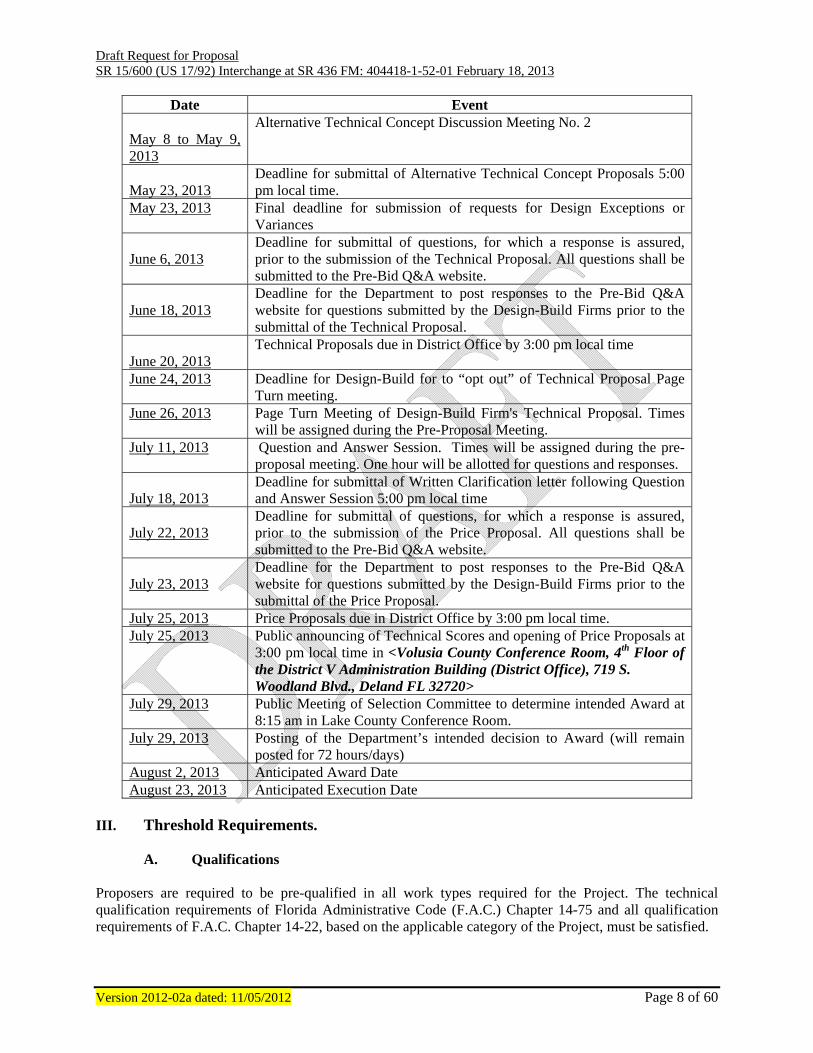
Date Event May 8 to May 9, 2013
Alternative Technical Concept Discussion Meeting No. 2
May 23, 2013
Deadline for submittal of Alternative Technical Concept Proposals 5:00 pm local time.
May 23, 2013 Final deadline for submission of requests for Design Exceptions or Variances
June 6, 2013
Deadline for submittal of questions, for which a response is assured, prior to the submission of the Technical Proposal. All questions shall be submitted to the Pre-Bid Q&A website.
June 18, 2013
Deadline for the Department to post responses to the Pre-Bid Q&A website for questions submitted by the Design-Build Firms prior to the submittal of the Technical Proposal.
June 20, 2013
Technical Proposals due in District Office by 3:00 pm local time
June 24, 2013 Deadline for Design-Build for to “opt out” of Technical Proposal Page Turn meeting.
June 26, 2013 Page Turn Meeting of Design-Build Firm's Technical Proposal. Times will be assigned during the Pre-Proposal Meeting.
July 11, 2013 Question and Answer Session. Times will be assigned during the pre-proposal meeting. One hour will be allotted for questions and responses.
July 18, 2013
Deadline for submittal of Written Clarification letter following Question and Answer Session 5:00 pm local time
July 22, 2013
Deadline for submittal of questions, for which a response is assured, prior to the submission of the Price Proposal. All questions shall be submitted to the Pre-Bid Q&A website.
July 23, 2013
Deadline for the Department to post responses to the Pre-Bid Q&A website for questions submitted by the Design-Build Firms prior to the submittal of the Price Proposal.
July 25, 2013 Price Proposals due in District Office by 3:00 pm local time. July 25, 2013 Public announcing of Technical Scores and opening of Price Proposals at
3:00 pm local time in <Volusia County Conference Room, 4th Floor of the District V Administration Building (District Office), 719 S. Woodland Blvd., Deland FL 32720>
July 29, 2013 Public Meeting of Selection Committee to determine intended Award at 8:15 am in Lake County Conference Room.
July 29, 2013 Posting of the Department’s intended decision to Award (will remain posted for 72 hours/days)
August 2, 2013 Anticipated Award Date August 23, 2013 Anticipated Execution Date
III. Threshold Requirements.
A. Qualifications Proposers are required to be pre-qualified in all work types required for the Project. The technical qualification requirements of Florida Administrative Code (F.A.C.) Chapter 14-75 and all qualification requirements of F.A.C. Chapter 14-22, based on the applicable category of the Project, must be satisfied.

Draft Request for Proposal SR 15/600 (US 17/92) Interchange at SR 436 FM: 404418-1-52-01 February 18, 2013
Version 2012-02a dated: 11/05/2012 Page 9 of 60
B. Joint Venture Firm Two or more Firms submitting as a Joint Venture must meet the Joint Venture requirements of Section 14-22.007, Florida Administrative Code. Parties to a Joint Venture must submit a Declaration of Joint Venture and Power of Attorney Form No. 375-020-18, prior to the deadline for receipt of Letters of Interest. If the Proposer is a Joint Venture, the individual empowered by a properly executed Declaration of Joint Venture and Power of Attorney Form shall execute the proposal. The proposal shall clearly identify who will be responsible for the engineering, quality control, and geotechnical and construction portions of the Work.
C. Price Proposal Guarantee A Price Proposal guaranty in an amount of not less than five percent (5%) of the total bid amount shall accompany each Proposer’s Price Proposal. The Price Proposal guaranty may, at the discretion of the Proposer, be in the form of a cashier’s check, bank money order, bank draft of any national or state bank, certified check, or surety bond, payable to the Department. The surety on any bid bond shall be a company recognized to execute bid bonds for contracts of the State of Florida. The Price Proposal guaranty shall stand for the Proposer’s obligation to timely and properly execute the contract and supply all other submittals due therewith. The amount of the Price Proposal guaranty shall be a liquidated sum, which shall be due in full in the event of default, regardless of the actual damages suffered. The Price Proposal guaranty of all Proposers’ shall be released pursuant to 3-4 of the Division I Design-Build Specifications.
D. Pre-Proposal Meeting Attendance at the pre-proposal meeting is mandatory. Any affirmatively declared proposer failing to attend will be deemed non-responsive and automatically disqualified from further consideration. The purpose of this meeting is to provide a forum for the Department to discuss with all concerned parties the proposed Project, the design and construction criteria, CPM schedule, and method of compensation, instructions for submitting proposals, design exceptions/variances, and other relevant issues. In the event that any discussions at the pre-proposal meeting require, in the Department's opinion, official additions, deletions, or clarifications of the Request for Proposal, the Design and Construction Criteria, or any other document, the Department will issue a written addendum to this Request for Proposals as the Department determines is appropriate. No oral representations or discussions, which take place at the pre-proposal meeting, will be binding on the Department. FHWA will be invited on oversight Projects, in order to discuss the Project in detail and to clarify any concerns. Proposers shall direct all questions to the Departments Question and Answer website: http://www2.dot.state.fl.us/construction/bidquestionmain.asp. During and after the meeting, it is the responsibility of the Project Manager/Contracting Unit to ensure that each Proposer develops their technical proposal with the same information. If a Proposer receives information from the Department relating to the Project, the Department will ensure that all Proposers receive the same information in a timely fashion. The Project file will clearly document all communications with any Firm regarding the design and construction criteria by the Contracting Unit or the Project Manager.
E. Page Turn Meeting
The Department will meet with each Proposer, formally for thirty (30) minutes, for a page-turn meeting. FHWA will be invited on FA Oversight Projects. The purpose of the page-turn meeting is for the Design-

Draft Request for Proposal SR 15/600 (US 17/92) Interchange at SR 436 FM: 404418-1-52-01 February 18, 2013
Version 2012-02a dated: 11/05/2012 Page 10 of 60
Build Firm to guide the Technical Review Committee through the Technical Proposal, highlighting sections within the Technical Proposal that the Design-Build Firm wishes to emphasize. The page-turn meeting will occur between the date the Technical Proposal is due and the Question and Answer session occurs, per the Schedule of Events section of this RFP. The Department will terminate the page-turn meeting promptly at the end of the allotted time. The Department will audiotape record or videotape all or part of the page-turn meeting. All audiotape recordings or videotape recordings will become part of the Contract Documents. The page-turn meeting will not constitute discussions or negotiations. The Design-Build Firm will not be permitted to ask questions of the Technical Review Committee during the page-turn meeting. An unmodified aerial or map of the project limits provided by the Design-Build Firm is acceptable for reference during the page-turn meeting. The unmodified aerial or map may not be left with the Department upon conclusion of the page turn meeting. Use of other visual aids, electronic presentations, handouts, etc., during the page turn meeting is expressly prohibited. Upon conclusion of the thirty (30) minutes, the Technical Review Committee is allowed five (5) minutes to ask questions pertaining to information highlighted by Design-Build Firm. Participation in the page-turn meeting by the Design-Build Firm shall be limited to five (5) representatives from the Design-Build Firm. Design-Build Firms desiring to opt out of the page-turn meeting may do so by submitting a request to the Department.
F. Question and Answer Session The Department may meet with each Proposer, formally, for a Question and Answer session. FHWA shall be invited on FA Oversight Projects. The purpose of the Q & A session is for the Technical Review Committee to seek clarification and ask questions, as it relates to the Technical Proposal, of the Proposer. The Department may terminate the Q & A session promptly at the end of the allotted time. The Department may audiotape record or videotape all or part of the Q & A session. All audiotape recordings or videotape recordings will become part of the Contract Documents. The Q & A session will not constitute “discussions” or negotiations. Proposers will not be permitted to ask questions of the Department except to ask the meaning of a clarification question posed by the Department. No supplemental materials, handouts, etc. will be allowed to be presented in the Q & A session. No additional time will be allowed to research answers. Within one (1) week of the Q & A session, the Design-Build Firm shall submit to the Department a written clarification letter summarizing the answers provided during the Q & A session. The Design-Build Firm shall not include information in the clarification letter which was not discussed during the Q&A session. In the event the Design-Build Firm includes additional information in the clarification letter which was not discussed during the Q&A session and is not otherwise included in the Technical Proposal, such additional information will not be considered by the Department during the evaluation of the Technical Proposal.
The Department will provide some (not necessarily all) proposed questions to each Design-Build Firm as it relates to their technical proposal approximately 24 hours before the scheduled Q & A session.
G. Protest Rights Any person who is adversely affected by the specifications contained in this Request for Proposal must file a notice of intent to protest in writing within seventy-two hours of the receipt of this Request for Proposals. The formal written protest shall be filed within ten days after the date of the notice of protest if filed. The person filing the Protest must send the notice of intent and the formal written protest to:
Clerk of Agency Proceedings Department of Transportation 605 Suwannee Street, MS 58, Room 562

Draft Request for Proposal SR 15/600 (US 17/92) Interchange at SR 436 FM: 404418-1-52-01 February 18, 2013
Version 2012-02a dated: 11/05/2012 Page 11 of 60
Tallahassee, Florida 32399-0458 The formal written protest must state with particularity the facts and law upon which the protest is based and be legible, on 8 ½ x 11-inch white paper and contain the following:
1. Name, address, telephone number, and Department identifying number on the Notice, if
known, and name, address and telephone number of a representative, if any; and 2. An explanation of how substantial interest will be affected by the action described in the
Request for Proposals; and 3. A statement of when and how the request for Proposals was received; and 4. A statement of all disputed issues of material fact. If there are none, this must be indicated;
and 5. A concise statement of the ultimate facts alleged, as well as the rules and statutes, which
entitle to relief; and 6. A demand for relief; and 7. Conform to all other requirements set out in Florida Statutes (F.S.), Chapter 120 and F.A.C.,
Chapter 28-106, including but not limited to Section 120.57 F.S. and Rules 28-106.301, F.A.C., as may be applicable.
A formal hearing will be held if there are disputed issues of material fact. If a formal hearing is held, this matter will be referred to the Division of Administrative Hearings, where witnesses and evidence may be presented and other witnesses may be cross-examined before an administrative law judge. If there are no disputed issues of material fact, an informal hearing will be held, in which case the person filing the protest will have the right to provide the Department with any written documentation or legal arguments which they wish the Department to consider. Mediation pursuant to Section 120.573, F.S., may be available if agreed to by all parties, and on such terms as may be agreed upon by all parties. The right to administrative hearing is not affected when mediation does not result in a settlement. Failure to file a protest within the time prescribed in Section 120.57(3), F.S., shall constitute a waiver of proceedings under Chapter 120, F.S.
H. Non-Responsive Proposals
Proposals found to be non-responsive shall not be considered. Proposals may be rejected if found to be in nonconformance with the requirements and instructions herein contained. A proposal may be found to be non-responsive by reasons, including, but not limited to, failure to utilize or complete prescribed forms, conditional proposals, incomplete proposals, indefinite or ambiguous proposals, failure to meet deadlines and improper and/or undated signatures. Other conditions which may cause rejection of proposals include evidence of collusion among Proposers, obvious lack of experience or expertise to perform the required work, submission of more than one proposal for the same work from an individual, firm, joint venture, or corporation under the same or a different name (also included for Design-Build Projects are those proposals wherein the same Engineer is

Draft Request for Proposal SR 15/600 (US 17/92) Interchange at SR 436 FM: 404418-1-52-01 February 18, 2013
Version 2012-02a dated: 11/05/2012 Page 12 of 60
identified in more than one proposal), failure to perform or meet financial obligations on previous contracts, employment of unauthorized aliens in violation of Section 274A (e) of the Immigration and Nationalization Act, or in the event an individual, firm, partnership, or corporation is on the United States Comptroller General's List of Ineligible Design-Build Firms for Federally Financed or Assisted Projects. Proposals will also be rejected if not delivered or received on or before the date and time specified as the due date for submission.
I. Waiver of Irregularities The Department may waive minor informalities or irregularities in proposals received where such is merely a matter of form and not substance, and the correction or waiver of which is not prejudicial to other Proposers. Minor irregularities are defined as those that will not have an adverse effect on the Department's interest and will not affect the price of the Proposals by giving a Proposer an advantage or benefit not enjoyed by other Proposers.
1. Any design submittals that are part of a proposal shall be deemed preliminary only. 2. Preliminary design submittals may vary from the requirements of the Design and
Construction Criteria. The Department, at their discretion, may elect to consider those variations in awarding points to the proposal rather than rejecting the entire proposal.
3. In no event will any such elections by the Department be deemed to be a waiving of the
Design and Construction Criteria. 4. The Proposer who is selected for the Project will be required to fully comply with the Design
and Construction Criteria for the price bid, regardless that the proposal may have been based on a variation from the Design and Construction Criteria.
5. Proposers shall identify separately all innovative aspects as such in the Technical Proposal.
An innovative aspect does not include revisions to specifications or established Department policies. Innovation should be limited to Design-Build Firm’s means and methods, roadway alignments, approach to Project, use of new products, new uses for established products, etc.
6. The Proposer shall obtain any necessary permits or permit modifications not already
provided. 7. Those changes to the Design Concept may be considered together with innovative
construction techniques, as well as other areas, as the basis for grading the Technical Proposals in the area of innovative measures.
J. Modification or Withdrawal of Technical Proposal
Proposers may modify or withdraw previously submitted Technical Proposals at any time prior to the Technical Proposal due date. Requests for modification or withdrawal of a submitted Technical Proposal shall be in writing and shall be signed in the same manner as the Technical Proposal. Upon receipt and acceptance of such a request, the entire Technical Proposal will be returned to the Proposer and not considered unless resubmitted by the due date and time. Proposers may also send a change in sealed envelope to be opened at the same time as the Technical Proposal provided the change is submitted prior to the Technical Proposal due date.
Draft Request for Proposal SR 15/600 (US 17/92) Interchange at SR 436 FM: 404418-1-52-01 February 18, 2013
Version 2012-02a dated: 11/05/2012 Page 13 of 60
K. Department’s Responsibilities This Request for Proposal does not commit the Department to make studies or designs for the preparation of any proposal, nor to procure or contract for any articles or services. The Department does not guarantee the details pertaining to borings, as shown on any documents supplied by the Department, to be more than a general indication of the materials likely to be found adjacent to holes bored at the site of the work, approximately at the locations indicated.
L. Design-Build Contract The Department will enter into a Lump Sum contract with the successful Design-Build Firm. In accordance with Section V, the Design-Build Firm will provide a schedule of values to the Department for their approval. The total of the Schedule of Values will be the lump sum contract amount. The terms and conditions of this contract are fixed price and fixed time. The Design-Build Firm’s submitted bid (time and cost) is to be a lump sum bid for completing the scope of work detailed in the Request for Proposal. IV. Disadvantaged Business Enterprise (DBE) Program.
A. DBE Availability Goal Percentage The Department of Transportation has an overall eight and six tenths percent (8.6%) race-neutral DBE goal. This means that the State’s goal is to spend at least 8.6% of the highway dollars with Certified DBE’s as prime Design-Build Firms or as subcontractors. Race-neutral means that the Department believes that the 8.6% overall goal can be achieved through the normal competitive procurement process. The Department has reviewed this Project and assigned a DBE availability goal shown on the bid blank/contract front page under “% DBE Availability Goal”. Although not a contract requirement, the Department believes that this DBE percentage can realistically be achieved on this Project based on the number of DBE’s associated with the different types of work that will be required. Under 49 Code of Federal Regulations Part 26, if the 8.6% goal is not achieved, the Department may be required to return to a race-conscious program where goals are imposed on individual contracts. The Department encourages all of our Design-Build Firms to actively pursue obtaining bids and quotes from Certified DBE’s.
B. Anticipated DBE Participation Statement
The Department is reporting to the Federal Highway Administration the planned commitments to use DBE’s. This information is being collected through the Anticipated DBE Participation Statement. This statement shall be submitted to the District Contract Compliance Manager/ Resident Compliance Officer who will then submit it electronically to the Equal Opportunity Office. Although these statements WILL NOT become a mandatory part of the contract, they will assist the Department in tracking and reporting planned or estimated DBE utilization.
C. Equal Opportunity Reporting System
The Design-Build Firm is required to report monthly, through the Department’s Equal Opportunity Reporting System on the Internet at, http://www.dot.state.fl.us/equalopportunityoffice/ actual payments, minority status, and the work type of all subcontractors and suppliers. All DBE payments must be reported whether or not the prime initially planned to utilize the company. Each month the prime must

Draft Request for Proposal SR 15/600 (US 17/92) Interchange at SR 436 FM: 404418-1-52-01 February 18, 2013
Version 2012-02a dated: 11/05/2012 Page 14 of 60
report actual payments to all DBE and MBE subcontractors and suppliers. In order for the race neutral DBE Program to be successful, cooperation is imperative.
D. DBE Supportive Services Providers
The Department has contracted with a consultant, referred to as DBE Supportive Services Provider, to provide managerial and technical assistance to DBE’s. This consultant is also required to work with prime Design-Build Firms, who have been awarded contracts, to assist in identifying DBE’s that are available to participate on the Project. The successful Design-Build Firm should meet with the DBE Supportive Services Provider to discuss the DBE’s that are available to work on this Project. The current Provider for the State of Florida is serviced by Blackmon Roberts Group and can be reached at (863) 802-1280 in Lakeland or (305) 777-0231 in Coral Gables.
E. DBE Affirmative Action Plan
A DBE Affirmative Action Plan must be approved and on file with the Equal Opportunity Office prior to award of the contract for each prime Design-Build Firm. Update and resubmit the plan every three years. No Contract will be awarded until the Department approves the plan. The DBE Affirmative Action Plan must be on your company’s letterhead, signed by a company official, dated and contain all elements of an effective DBE Affirmative Action Plan. These Plans should be mailed to:
Florida Department of Transportation Equal Opportunity Office 605 Suwannee Street, MS 65 Tallahassee, FL 32399-0450
Questions concerning the DBE Affirmative Action Plan may be directed to the Equal Opportunity Office by calling (850) 414-4747.
F. Bidders Opportunity List
The Federal DBE Program requires States to maintain a database of all Firms that are participating, or attempting to participate, on DOT-assisted contracts. The list must include all Firms that bid on prime contracts or bid or quote subcontracts on DOT-assisted Projects, including both DBE’s and Non-DBE’s. On the Bidders Opportunity Form if the answers to numbers 2, 3, 4, or 5 are not known, leave them blank and the Department will complete the information. This information should be returned with the bid package or proposal package or submitted to the Equal Opportunity Office within three days of submission. It can be mailed to the Equal Opportunity Office or faxed to (850) 414-4879. V. Project Requirements and Provisions for Work
A. Governing Regulations The services performed by the Design-Build Firm shall be in compliance with all applicable Manuals and Guidelines including the Department, FHWA, AASHTO, and additional requirements specified in this document. Except to the extent inconsistent with the specific provisions in this document, the current edition, including updates, of the following Manuals and Guidelines shall be used in the performance of this work. Current edition is defined as the edition in place and adopted by the Department at the date of advertisement of this contract with the exception of the Standard Specifications for Road and Bridge Construction (Divisions II & III), Special Provisions and Supplemental Specifications, Manual on

Draft Request for Proposal SR 15/600 (US 17/92) Interchange at SR 436 FM: 404418-1-52-01 February 18, 2013
Version 2012-02a dated: 11/05/2012 Page 15 of 60
Uniform Traffic Control Devices (MUTCD), Design Standards and Design Standards Modifications. The Design-Build Firm shall use the edition of the Standard Specifications for Road and Bridge Construction (Divisions II & III), Special Provisions and Supplemental Specifications, Design Standards and Design Standard Modifications in effect at the time the bid price proposals are due in the District Office. The Design-Build Firm shall use the 2009 edition of the MUTCD. It shall be the Design-Build Firm's responsibility to acquire and utilize the necessary manuals and guidelines that apply to the work required to complete this Project. The services will include preparation of all documents necessary to complete the Project as described in Section I of this document.
1. Florida Department of Transportation Roadway Plans Preparation Manuals (PPM) http://www.dot.state.fl.us/rddesign/PPMManual/PPM.shtm
2. Florida Department of Transportation Design Standards http://www.dot.state.fl.us/rddesign/DesignStandards/Standards.shtm
3. Florida Department of Transportation Standard Specifications for Road and Bridge Construction (Divisions II & III), Special Provisions and Supplemental Specifications http://www.dot.state.fl.us/specificationsoffice/Default.shtm
4. Florida Department of Transportation Surveying Procedure http://www2.dot.state.fl.us/proceduraldocuments/procedures/bin/550030101.pdf
5. Florida Department of Transportation EFB User Handbook (Electronic Field Book) http://www.dot.state.fl.us/surveyingandmapping/regulations.shtm
6. Florida Department of Transportation Drainage Manual
http://www.dot.state.fl.us/rddesign/dr/Manualsandhandbooks.shtm 7. Florida Department of Transportation Soils and Foundations Handbook
http://www.dot.state.fl.us/structures/Manuals/SFH.pdf 8. Florida Department of Transportation Structures Manual
http://www.dot.state.fl.us/structures/manlib.shtm
9. Florida Department of Transportation Current Structures Design Bulletins http://www.dot.state.fl.us/structures/Memos/currentbulletins.shtm
10. Florida Department of Transportation Computer Aided Design and Drafting (CADD) Production Criteria Handbook http://www.dot.state.fl.us/ecso/downloads/publications/CriteriaHandBook/
11. Florida Department of Transportation Production Criteria Handbook CADD Structures Standards http://www.dot.state.fl.us/ecso/downloads/publications/CriteriaHandBook/
12. Instructions for Design Standards http://www.dot.state.fl.us/structures/IDS/IDSportal.pdf
13. AASHTO – A Policy on Geometric Design of Highways and Streets https://bookstore.transportation.org/item_details.aspx?ID=110
14. MUTCD - 2009 http://mutcd.fhwa.dot.gov/
15. Safe Mobility For Life Program Policy Statement http://www2.dot.state.fl.us/proceduraldocuments/procedures/bin/000750001.pdf

Draft Request for Proposal SR 15/600 (US 17/92) Interchange at SR 436 FM: 404418-1-52-01 February 18, 2013
Version 2012-02a dated: 11/05/2012 Page 16 of 60
16. Traffic Engineering and Operations Safe Mobility for Life Program http://www.dot.state.fl.us/trafficoperations/Operations/SafetyisGolden.shtm
17. Florida Department of Transportation American with Disabilities Act (ADA) Compliance – Facilities Access for Persons with Disabilities Procedure http://www2.dot.state.fl.us/proceduraldocuments/procedures/bin/625020015.pdf
18. Florida Department of Transportation Florida Sampling and Testing Methods http://www.dot.state.fl.us/statematerialsoffice/administration/resources/library/publications/fstm/disclaimer.shtm
19. Florida Department of Transportation Flexible Pavement Coring and Evaluation Procedure http://www.dot.state.fl.us/statematerialsoffice/administration/resources/library/publications/materialsmanual/documents/v1-section32-clean.pdf
20. Florida Department of Transportation Design Bulletins and Update Memos http://www.dot.state.fl.us/rddesign/updates/files/updates.shtm
21. Florida Department of Transportation Utility Accommodation Manual http://www.dot.state.fl.us/rddesign/utilities/UAM.shtm
22. AASHTO LRFD Bridge Design Specifications https://bookstore.transportation.org/category_item.aspx?id=BR
23. Florida Department of Transportation Flexible Pavement Design Manual http://www.dot.state.fl.us/rddesign/PM/publicationS.shtm
24. Florida Department of Transportation Rigid Pavement Design Manual http://www.dot.state.fl.us/rddesign/PM/publicationS.shtm
25. Florida Department of Transportation Pavement Type Selection Manual http://www.dot.state.fl.us/rddesign/PM/publicationS.shtm
26. Florida Department of Transportation Right of Way Manual http://www.dot.state.fl.us/rightofway/Documents.shtm
27. Florida Department of Transportation Traffic Engineering Manual http://www.dot.state.fl.us/TrafficOperations//Operations/Studies/TEM/TEM.shtm
28. Florida Department of Transportation Intelligent Transportation System Guide Book http://www.dot.state.fl.us/TrafficOperations/Doc_Library/Doc_Library.shtm
29. Federal Highway Administration Checklist and Guidelines for Review of Geotechnical Reports and Preliminary Plans and Specifications http://www.fhwa.dot.gov/engineering/geotech/pubs/reviewguide/checklist.cfm
30. Florida Department of Transportation Bicycle and Pedestrian Policies and Standards http://www.dot.state.fl.us/safety/ped_bike/ped_bike_standards.shtm
31. Federal Highway Administration Hydraulic Engineering Circular Number 18 (HEC 18). http://www.fhwa.dot.gov/engineering/hydraulics/library_arc.cfm?pub_number=17
32. Florida Department of Transportation Manual of Uniform Minimum Standards for Design, Construction and Maintenance for Streets and Highways http://www.dot.state.fl.us/rddesign/FloridaGreenbook/FGB.shtm
33. Florida Department of Transportation Project Development and Environment Manual, Parts 1 and 2

Draft Request for Proposal SR 15/600 (US 17/92) Interchange at SR 436 FM: 404418-1-52-01 February 18, 2013
Version 2012-02a dated: 11/05/2012 Page 17 of 60
http://www.dot.state.fl.us/emo/pubs/pdeman/pdeman1.shtm
34. Florida Statutes http://www.leg.state.fl.us/Statutes/index.cfm?Mode=View%20Statutes&Submenu=1&Tab=statutes&CFID=14677574&CFTOKEN=80981948
B. Innovative Aspects
All innovative aspects shall be identified separately as such in the Technical Proposal. An innovative aspect does not include revisions to specifications, standards or established Department policies. Innovation should be limited to Design-Build Firm’s means and methods, roadway alignments, approach to Project, etc.
1. Alternative Technical Concept (ATC) Proposals The ATC process allows innovation, flexibility, time and cost savings on the design and construction of Design-Build Projects while providing the best value for the public. ATC discussion meetings may be held in order for the Design-Build Firm to describe proposed changes to supplied basic configurations, Project scope, design criteria, and/or construction criteria. The alternative technical concept shall provide an approach that is equal to or better than what is required by the Request for Proposal (RFP), as determined by the Department. Concepts which reduce quality, performance, or reliability should not be proposed. A proposed concept is not an ATC if it is contemplated by the RFP.
Each Design-Build Firm with proposed changes may request an ATC discussion meeting to describe the proposed changes. The Design-Build Firm shall provide a preliminary list of ATC proposals, to be reviewed and discussed during the ATC discussion meeting, by the deadline shown in the Schedule of Events of this RFP. This list may not be inclusive of all ATC’s to be discussed but it should be comprehensively sufficient to allow the Department to identify appropriate personnel which should attend the ATC discussion meeting. The purpose of the ATC discussion meeting is to discuss the ATC proposals, answer questions that the Department may have related to the ATC proposal, review other relevant information and when possible establish whether the proposal meets the definition of an ATC thereby requiring the submittal of a formal ATC submittal. The meeting should be between representatives of the Design-Build Firm and/or the Design-Build Engineer of Record and District/Central Office staff as needed to provide feedback on the ATC proposal.
2. Submittal of ATC Proposals
All ATC submittals must be in writing and may be submitted at any time following the Shortlist Posting but shall be submitted prior to the deadline shown in the Schedule of Events of this RFP. All ATC submittals shall be sequential numbered and include the following information and discussions:
a) Description: A description and conceptual drawings of the configuration of the ATC or other appropriate descriptive information, including, if appropriate, product details and a traffic operational analysis;
b) Usage: The locations where and an explanation of how the ATC would be used on the
Project; c) Deviations: References to requirements of the RFP which are inconsistent with the proposed

Draft Request for Proposal SR 15/600 (US 17/92) Interchange at SR 436 FM: 404418-1-52-01 February 18, 2013
Version 2012-02a dated: 11/05/2012 Page 18 of 60
ATC, an explanation of the nature of the deviations from the requirements and a request for approval of such deviations along with suggested changes to the requirements of the RFP which would allow the alternative proposal;
d) Analysis: An analysis justifying use of the ATC and why the deviation, if any, from the
requirements of the RFP should be allowed; e) Impacts: A preliminary analysis of potential impacts on vehicular traffic (both during and
after construction), environmental impacts, community impacts, safety, and life-cycle Project and infrastructure costs, including impacts on the cost of repair, maintenance, and operation;
f) Risks: A description of added risks to the Department or third parties associated with
implementation of the ATC; g) Quality: A description of how the ATC is equal or better in quality and performance than the
requirements of the RFP; and h) Operations: Any changes in operation requirements associated with the ATC, including ease
of operations; i) Maintenance: Any changes in maintenance requirements associated with the ATC, including
ease of maintenance; j) Anticipated Life: Any changes in the anticipated life of the item comprising the ATC; k) *Handback: Any changes in Handback Requirements associated with the ATC; l) *Project Revenue: A preliminary analysis of potential impacts on Project Revenue; m) *Payments: A preliminary analysis of potential impacts on the Upfront Concession Payment
and Annual Lease Payment
* These submittal requirements will be needed for Public Private Partnership (PPP) Projects only.
3. Review of ATC Submittals After receipt of the ATC submittal, the District Design Engineer (DDE) will communicate with the appropriate staff (i.e. District Structures Engineer, District Construction Engineer, District Maintenance Engineer, State Structures Engineer, State Roadway Design Engineer, FHWA, as applicable) as necessary, and respond to the Design-Build Firm in writing as to whether the ATC is acceptable, not acceptable, or requires additional information within 14 calendar days of receipt of the ATC submittal. If the DDE or designee determines that more information is required for the review of an ATC, questions should be prepared by the DDE or designee to request and receive responses from the Design-Build Firm. The review should be completed within 14 calendar of the receipt of the ATC submittal. If the review will require additional time, the Design-Build Firm should be notified in advance with an estimated timeframe for completion. If the ATC will result in changes to design standards or criteria, the changes will need to be approved in accordance with the Department’s procedures prior to responding to the Design-Build Firm. The Project file will clearly document all communications with any Design-Build Firm.

Draft Request for Proposal SR 15/600 (US 17/92) Interchange at SR 436 FM: 404418-1-52-01 February 18, 2013
Version 2012-02a dated: 11/05/2012 Page 19 of 60
ATC’s are accepted by the Department at its discretion and the Department reserves the right to reject any ATC submitted. The Department will issue an addendum to the RFP subsequent to acceptance of any ATC. Such a change will be approved by FHWA, as applicable. Approved Design Exceptions or Design Variances will result in an addendum to the RFP. The Department reserves the right to disclose to all Design-Build Firms any issues raised during the ATC meetings, except to the extent that FDOT determines, in its sole discretion, such disclosure would reveal confidential or proprietary information of the ATC.
4. Incorporation into Proposal The Design-Build Firm will have the option to include any ATC’s to which it received acceptance in their proposal and the Proposal Price should reflect any incorporated ATC’s. By submitting a Proposal, the Design-Build Firm agrees, if it is not selected, to disclosure of its work product to the successful Design-Build Firm, only after receipt of the designated stipend (if applicable) or after award of the contract whichever occurs first.
C. Geotechnical Services
1. General Conditions
The Design-Build Firm shall be responsible for identifying and performing any geotechnical investigation, analysis and design of foundations, foundation construction, foundation load and integrity testing, and inspection dictated by the Project needs in accordance with Department guidelines, procedures and specifications. All geotechnical work necessary shall be performed in accordance with the Governing Regulations. The Design-Build Firm shall be solely responsible for all geotechnical aspects of the Project.
D. Department Commitments The Design-Build Firm will be responsible for adhering to the project commitments identified below:
1. Typical Section Package 2. Pavement Design 3. Right-of-way 4. Two (2) LFA Agreements 5. Permits 6. Lump Sum Utility Work by Highway Contractor
E. Environmental Permits
1. Storm Water and Surface Water
Plans shall be prepared in accordance with Chapters 373 and 403 (F.S.) and Chapters 40 and 62 (F.A.C.).
2. Permits
Draft Request for Proposal SR 15/600 (US 17/92) Interchange at SR 436 FM: 404418-1-52-01 February 18, 2013
Version 2012-02a dated: 11/05/2012 Page 20 of 60
All applicable data shall be prepared in accordance with Chapter 373 and 403, Florida Statutes, Chapters 40 and 62, Florida Administrative Code; Rivers and Harbors Act of 1899, Section 404 of the Clean Water Act, 23 CFR 771, 23 CFR 636, and parts 114 and 115, Title 33, Code of Federal Regulations. In addition to these Federal and State permitting requirements, any dredge and fill permitting required by local agencies shall be prepared in accordance with their specific regulations. Acquisition of all applicable permits will be the responsibility of the Design-Build Firm. Preparation of complete permit packages will be the responsibility of the Design-Build Firm. As the permitee, the Department is responsible for reviewing, approving, and signing, the permit application package including all permit modifications, or subsequent permit applications. This applies whether the project is Federal or state funded. If any agency rejects or denies the permit application, it is the Design-Build Firm’s responsibility to make whatever changes necessary to ensure the permit is approved.
The Design-Build Firm will be required to pay all permit fees. Any fines levied by permitting agencies shall be the responsibility of the Design-Build Firm. However, notwithstanding anything above to the contrary, upon the Design-Build Firm’s preliminary request for extension of Contract Time, pursuant to 8-7.3, being made directly to the District Construction Engineer, the Department reserves unto the District Construction Engineer, in their sole and absolute discretion, according to the parameters set forth below, the authority to make a determination to grant a non-compensable time extension for any impacts beyond the reasonable control of the Design-Build Firm in securing permits. Furthermore, as to any such impact, no modification provision will be considered by the District Construction Engineer unless the Design-Build Firm clearly establishes that it has continuously from the beginning of the Project aggressively, efficiently and effectively pursued the securing of the permits including the utilization of any and all reasonably available means and methods to overcome all impacts. There shall be no right of any kind on behalf of the Design-Build Firm to challenge or otherwise seek review or appeal in any forum of any determination made by the District Construction Engineer under this provision.
F. Railroad Coordination
Railroad Coordination will not be required for this project. There are no railroads within the project limits.
G. Survey The Design-Build Firm shall perform all surveying and mapping services necessary to complete the Project. Survey services must also comply with all pertinent Florida Statutes and applicable rules in the Florida Administrative Code. All field survey data will be furnished to the District Surveyor in a Department approved digital format, readily available for input and use in CADD Design files. All surveying and mapping work must be accomplished in accordance with the Department’s Surveying Procedure, Topic Nos. 550-030-101; Right-of-Way Mapping Procedure, Topic No. 550-030-015; Aerial Surveying Standards for Transportation Projects Procedure, Topic No. 550-020-002. This work must comply with the Minimum Technical Standards for Professional Surveyors and Mappers, Chapter 5J-17, Florida Administrative Code (F.A.C.), pursuant to Section 472.027, Florida Statutes (F.S.) and any special instructions from the Department. This survey also must comply with the Department of Environmental Protection Rule, Chapter 18-5, F.A.C. pursuant to Chapter 177, F.S., and the Department of Environmental Protection.
H. Verification of Existing Conditions

Draft Request for Proposal SR 15/600 (US 17/92) Interchange at SR 436 FM: 404418-1-52-01 February 18, 2013
Version 2012-02a dated: 11/05/2012 Page 21 of 60
The Design-Build Firm shall be responsible for verification of existing conditions, including research of all existing Department records and other information.
By execution of the contract, the Design-Build Firm specifically acknowledges and agrees that the Design-Build Firm is contracting and being compensated for performing adequate investigations of existing site conditions sufficient to support the design developed by the Design-Build Firm and that any information is being provided merely to assist the Design-Build Firm in completing adequate site investigations. Notwithstanding any other provision in the contract documents to the contrary, no additional compensation will be paid in the event of any inaccuracies in the preliminary information.
I. Submittals
1. Plans
Plans must meet the minimum contents of a particular phase submittal prior to submission for review. The particular phase of each submittal shall be clearly indicated on the cover sheet. Component submittals must be accompanied by sufficient information for adjoining components or areas of work to allow for proper evaluation of the component under review. Submittals for Category I and II bridges are limited to the following component submittals: foundation, substructure, and superstructure. Bridge component submittals must be accompanied by all supplemental information required for a complete review. Submittals for individual component elements (i.e. Pier 2, Abutment 1, Span 4, etc.) and incomplete submittals will not be accepted. Category I and II bridge component submittals shall contain the following:
Plan sheets for the component under review developed to the specified level of detail (i.e. 90% plans, Final plans, etc.),
A complete set of the most developed plan sheets for all other major elements of the bridge. These sheets shall be marked “For Information Only” on the index sheet. In no case shall a plan sheet be less than 30% complete.
Design documentation including a complete set of calculations, geotechnical reports, pertinent correspondence, etc. in support of the 90% and final component submittals.
For Category II bridges component submittals shall also include independent peer review documentation.
The Design-Build Firm shall provide copies of required review documents as listed below.
90% Component Plans:
16 sets of 11” X 17” roadway plans 9 sets of 11” X 17” structure plans 8 sets of 11” X 17” each component set (including but not limited to the City of
Casselberry’s water and sewer plans should they require redesign), except ITS plans
5 sets of 11” X 17” ITS plans 7 copies of Final Geotechnical Report 3 copies of Final Bridge Hydraulic Report 2 sets of documentation – roadway/drainage
Draft Request for Proposal SR 15/600 (US 17/92) Interchange at SR 436 FM: 404418-1-52-01 February 18, 2013
Version 2012-02a dated: 11/05/2012 Page 22 of 60
2 sets of documentation - structures 2 copies of Specifications Package 2 sets of 11” x 17” roadway, structure and component plans in Adobe Acrobat
format (.pdf) on CD 2 Bridge Load rating reports, with 2 load rating summary forms (excel fromat)
and 2 load rating detail tables (CADD) 2 sets of Independent Peer reviewer’s comments and comment responses
Final Component Plans:
16 sets of 11” X 17” roadway plans 9 sets of 11” X 17” structure plans 8 sets of 11” X 17” each component set, except ITS plans 5 sets of 11” X 17” ITS plans 2 sets of 11” x 17” roadway, structure and component plans in Adobe Acrobat
format (.pdf) on CD 2 sets of final documentation 1 signed and sealed copy of Specifications Package 2 sets of electronic copies of Technical Special Provisions on CD Independent Peer Reviewer’s signed and sealed cover letter that all comments
have been addressed and resolved.
Construction Set:
1 set of 11”X 17” copies of the signed and sealed plans for the Department to stamp “Released for construction”
1 “Release for Construction” Bridge Load Rating Summary Form (Excel format), and 1 Detail Table (CADD), both signed and sealed. Provide full report if rating revisions occur subsequent to the 90% Component Submittal.
Final signed and sealed plans will be delivered to the Department’s Project Manager a minimum of fifteen (15) calendar days (excluding Holidays as defined in section 1-3 of the Specifications) prior to construction of that component. Final signed and sealed plans related to Category II structures will be delivered to the Department’s Project Manager a minimum of twenty (20) calendar days (excluding Holidays as defined in section 1-3 of the Specifications) prior to construction of that component. The Department’s Project Manager will send a copy of a final signed and sealed plans to the appropriate office for review and comment. Once all comments have been satisfactorily resolved as determined by the Department, the Department’s Project Manger will initial, date and stamp each submittal as “Released for Construction”. Only signed and sealed plans which are stamped “Released for Construction” by the Department’s Project Manager are valid and all work that the Design-Build Firm performs in advance of the Department’s release of Plans will be at the Design-Build Firm’s risk.
Record Set:
The Design-Build Firm shall furnish to the Department, upon Project completion, the following:
1 set of 11” X 17” signed and sealed plans 2 sets of 11 "X 17” copies of the signed and sealed plans

Draft Request for Proposal SR 15/600 (US 17/92) Interchange at SR 436 FM: 404418-1-52-01 February 18, 2013
Version 2012-02a dated: 11/05/2012 Page 23 of 60
1 “Release for Construction” Bridge Load Rating Summary Form (Excel format), and 1 Detail Table (CADD), both signed and sealed. Provide full report if rating revisions occur subsequent to the 90% Component Submittal
2 sets of final documentation (if different from final component submittal) 2 (two) Final Project CD’s 2 sets of 11” x 17” as-built roadway, structure and component plans in Adobe
Acrobat format (.pdf) on CD The Design-Build Firm's Professional Engineer in responsible charge of the Project’s design shall professionally endorse (signed and sealed and certified) the record prints, the special provisions and all reference and support documents. The professional endorsement shall be performed in accordance with the Department Plans Preparation Manual. The Design-Build Firm shall complete the record set as the Project is being constructed. The record set becomes the as-builts at the end of the Project. All changes shall be signed/sealed by the EOR. The record set shall reflect all changes initiated by the Design-Build Firm or the Department in the form of revisions. The record set shall be submitted on a Final Project CD upon Project completion. The CEI shall do a review of the record set prior to final acceptance in order to complete the record set. The CEI shall certify the final plans as per Section 4.5.7 of Chapter 4 of the Preparation and Documentation Manual (TOPIC No. 700-050-010).
2. Railroad Coordination Railroad Coordination will not be required for this project.
J. Contract Duration The Design-Build Firm shall establish the contract duration for the subject Project. In no event shall the contract duration exceed 900 calendar days. The schedule supporting the proposed contract duration will be submitted with the Technical Proposal and should identify if the work activity durations are based on calendar days or working days. The Proposed Contract Time (PCT) reflected in the schedule may be amended in the bid proposal. The official PCT will be the one submitted with the Bid Price Proposal.
K. Project Schedule The Design-Build Firm shall submit a Project schedule, in accordance with Subarticle 8-3.2 (Design-Build Division I Specifications), which supports the established contract duration submitted as part of the Proposal. The Design-Build Firm’s schedule should allow for a fifteen (15) calendar days (excluding weekends and Department observed Holidays) review time for the Department’s review of all submittals with the exception of Category II structures. The review of Category II structures requires Central Office involvement and the schedule shall allow twenty (20) calendar days (excluding weekends and Department observed Holidays) for these reviews. The minimum number of activities shall be those listed in the payout schedule and those listed below:
Anticipated Award Date Design Submittals Design Survey

Draft Request for Proposal SR 15/600 (US 17/92) Interchange at SR 436 FM: 404418-1-52-01 February 18, 2013
Version 2012-02a dated: 11/05/2012 Page 24 of 60
Design Reviews by the Department and FHWA Design Review / Acceptance Milestones Materials Quality Tracking Geotechnical Investigation Start of Construction Clearing and Grubbing Construction Mobilization Embankment/Excavation Environmental Permit Acquisition Foundation Design Foundation Construction Substructure Design Substructure Construction Superstructure Design Superstructure Construction Walls Design Walls Construction Roadway Design Roadway Construction Signing and Pavement Marking Design Signing and Pavement Marking Construction Intelligent Transportation System Design Intelligent Transportation System Construction Aesthetics and Landscape Design Aesthetics and Landscape Construction Maintenance of Traffic Design Permit Submittals Maintenance of Traffic Set-Up (per duration) Erosion Control Holidays and Special Events (shown as non-work days) Utilities Plans Additional Construction Milestones as determined by the Design-Build Firm Final Completion Date for All Work
L. Key Personnel/Staffing
The Design-Build Firm’s work shall be performed and directed by key personnel identified in the expanded letter of interest and/or technical proposal by the Design-Build Firm. Any changes in the indicated personnel shall be subject to review and approval by the Department’s Project Manager. The Design-Build Firm shall have available a professional staff that meets the minimum training and experience set forth in Florida Statute Chapter 455.
M. Meetings and Progress Reporting The Design-Build Firm shall anticipate periodic meetings with Department personnel and other agencies as required for resolution of design and/or construction issues. These meetings may include:
Department technical issue resolution Permit agency coordination

Draft Request for Proposal SR 15/600 (US 17/92) Interchange at SR 436 FM: 404418-1-52-01 February 18, 2013
Version 2012-02a dated: 11/05/2012 Page 25 of 60
Local government agency coordination Scoping Meetings
During design, the Design-Build Firm shall meet with the Department’s Project Manager on a monthly basis and provide a month look ahead of the activities to be completed during the upcoming month. During construction, the Design-Build Firm shall meet with the Department’s Project Manager on a weekly basis and provide a one-week look ahead for activities to be performed during the coming week. The Design-Build Firm shall, on a monthly basis, provide written progress reports that describe the items of concern and the work performed on each task.
N. Public Involvement
1. General Public involvement is an important aspect of the Project. Public involvement includes communicating to all interested persons, groups, and government organizations information regarding the development of the Project. A Public Involvement Consultant (PIC) has been hired by the Department to carry out an exhaustive Public Involvement Campaign and a marketing effort. The Design-Build Firm will continue to be part of the Public Involvement effort but on a limited basis as described below.
2. Community Awareness The Design-Build Firm will review and comment on a Community Awareness Program provided by the PIC for the Project.
3. Public Meetings The Design-Build Firm shall provide all support necessary for the PIC to hold various public meetings, which may include:
Kick-off or introductory meeting Metropolitan Planning Organization (MPO) Citizens Advisory Committee
Meetings MPO Transportation Technical Committee Meetings MPO Meetings Public Information Meetings Elected and appointed officials Special interest groups (private groups, homeowners associations, environmental
groups, minority groups and individuals) The Design-Build Firm shall include attendance at two meetings per month for the term of the contract to support the public involvement program. For any of the above type meetings the Design-Build Firm shall provide all technical assistance, data and information necessary for the PIC to produce display boards, printed material, video graphics, computerized graphics, etc., and information necessary for the day-to-day exchange of information with the public, all agencies and elected officials in order to keep them informed as to the progress and impacts that the proposed Project will create. This includes workshops, information meetings, and public hearings.

Draft Request for Proposal SR 15/600 (US 17/92) Interchange at SR 436 FM: 404418-1-52-01 February 18, 2013
Version 2012-02a dated: 11/05/2012 Page 26 of 60
The Design-Build Firm shall, on an as-needed basis, attend the meetings with an appropriate number of personnel to assist the Department's Project Representative/PIC. The Design-Build Firm shall forward all requests for group meetings to the PIC. The Design-Build Firm shall inform the PIC of any meetings with individuals that occur without prior notice.
4. Public Workshops, Information Meetings The Design-Build Firm shall provide all the support services listed in No. 3 above. All legal/display ads announcing workshops, information meetings, and public meetings will be prepared and paid for by the PIC.
The Department will be responsible for the legal/display advertisements for design concept acceptance. The PIC will be responsible for preparing and mailing (includes postage) for all letters announcing workshops and information meetings.
5. Public Involvement Data The Design-Build Firm is responsible for the following:
Coordinating with the Public Involvement Consultant. Identifying possible permit and review agencies and providing names and contact
information for theses agencies to the PIC. Providing required expertise (staff members) to assist the PIC on an as-needed
basis. Preparing color graphic renderings and/or computer generated graphics to depict
the proposed improvements for coordination with the Department, local governments, the Urban Design Guidelines Committee, and other agencies.
The collection of public input occurs throughout the life of the Project and requires maintaining files, newspaper clippings, letters, and especially direct contacts before, during and after any of the public meetings. Articles such as those mentioned shall be provided to the PIC for their use and records. In addition to collecting public input data, the Design-Build Firm may be asked by the PIC to prepare responses to any public inquiries as a result of the public involvement process. The Department shall review all responses prior to mailing.
O. Quality Management Plan (QMP)
1. Design The Design-Build Firm shall be responsible for the professional quality, technical accuracy and coordination of all surveys, designs, drawings, specifications, geotechnical and other services furnished by the Design-Build Firm under this contract. The Design-Build Firm shall provide a Design Quality Management Plan, which describes the Quality Control (QC) procedures to be utilized to verify, independently check, and review all design drawings, specifications, and other documentation prepared as a part of the contract. In addition the QMP shall establish a Quality Assurance (QA) program to confirm that the Quality Control procedures are followed. The Design-Build Firm shall describe how the checking and review processes are to be documented to
Draft Request for Proposal SR 15/600 (US 17/92) Interchange at SR 436 FM: 404418-1-52-01 February 18, 2013
Version 2012-02a dated: 11/05/2012 Page 27 of 60
verify that the required procedures were followed. The QMP may be one utilized by the Design-Build Firm, as part of their normal operation or it may be one specifically designed for this Project. The Design-Build Firm shall submit a QMP within fifteen (15) working days following issuance of the written Notice to Proceed. A marked up set of prints from the Quality Control review will be sent in with each review submittal. The responsible Professional Engineers or Professional Surveyor that performed the Quality Control review, as well as the QA manager will sign a statement certifying that the review was conducted. The Design-Build Firm shall, without additional compensation, correct all errors or deficiencies in the surveys, designs, drawings, specifications and/or other services. No fabrication, casting, or construction will occur until all related design review and shop drawing review comments are resolved.
2. Construction The Design-Build Firm shall be responsible for developing and maintaining a Construction Quality Control Plan in accordance with Section 105 of Standard Specifications which describes their Quality Control procedures to verify, check, and maintain control of key construction processes and materials. The sampling, testing and reporting of all materials used shall be in compliance with the Sampling, Testing and Reporting Guide (STRG) provided by the Department. The Design-Build Firm will use the Department’s database(s) to allow audits of materials used to assure compliance with the STRG. The Department has listed the most commonly used materials and details in the Department’s database. When materials being used are not in the Department’s database list, the Design-Build Firm shall use appropriate material details from the STRG to report sampling and testing. Refer to the “Access Instruction for LIMS” for more information on how to gain access to the Department’s databases: http://www.dot.state.fl.us/statematerialsoffice/quality/programs/qualitycontrol/contractor.shtm Prepare and submit to the Engineer a Job Guide Schedule (JGS) using the Laboratory Information Management System (LIMS) in accordance with Section 105 of Standard Specifications. The Department shall maintain its rights to inspect construction activities and request any documentation from the Design-Build Firm to ensure quality products and services are being provided in accordance with the Department’s Materials Acceptance Program.
P. Liaison Office The Department and the Design-Build Firm will designate a Liaison Office and a Project Manager who shall be the representative of their respective organizations for the Project.
Q. Engineers Field Office The Design-Build Firm will provide an Engineers Field Office in accordance with Special Provision 109.
The Design-Build Firm shall provide, furnish and maintain a minimum 1,200 square foot on-site Engineer’s Field Office for exclusive use by the Department in accordance with Section 109 of the Specifications. If the Design-Build Firm sets an on-site field office, the Engineer’s Field office shall be located in the same fenced/enclosed area as the Design-Build Firm’s field office. The field office location is noted in the concept plans in each traffic control plan phase. The parcel is 102
Draft Request for Proposal SR 15/600 (US 17/92) Interchange at SR 436 FM: 404418-1-52-01 February 18, 2013
Version 2012-02a dated: 11/05/2012 Page 28 of 60
as shown in the right-of-way maps. The first paragraph of Section 109-2.3 Occupancy and Maintenance is revised as follows: 109-2.3 Occupancy and Maintenance: Provide a field office for Department use, beginning twenty (20) calendar days before construction begins and remaining for thirty (30) calendar day after final acceptance, unless the Department requests removal earlier. Do not begin construction before the field office is available for Department use.
R. Schedule of Values
The Design-Build Firm will be responsible for invoicing the Department based on current invoicing policy and procedure. Invoicing will be based on the completion or percentage of completion of major, well-defined tasks as defined in the schedule of values. Final payment will be made upon final acceptance by the Department of the Design-Build Project. Tracking DBE participation will be required under normal procedures according to the CPAM. The Design-Build Firm must submit the schedule of values to the Department for approval. No invoices shall be submitted prior to Department approval of the schedule of values.
Upon receipt of the invoice, the Department’s Project Manager will make judgment on whether or not work of sufficient quality and quantity has been accomplished by comparing the reported percent complete against actual work accomplished.
S. Computer Automation The Project shall be developed utilizing computer automation systems in order to facilitate the development of the contract plans. Various software and operating systems were developed to aid in assuring quality and conformance with Department of Transportation policies and procedures. Seed Files, Cell Libraries, User Commands, MDL Applications and related programs developed for roadway design and drafting are available for the MicroStation V8 format in the FDOT CADD Software Suite. However, it is the responsibility of the Design-Build Firm to obtain and utilize current Department releases of all CADD applications. The Design-Build Firm's role and responsibilities are defined in the Department's CADD Manual. The Design-Build Firm will be required to submit final documents and files which shall include complete CADD design and coordinate geometry files in Intergraph / Micro station format, as described in the above referenced document. The archived submittal shall also include either a TIMS database file, CADD Index file (generated from RDMENU) or documentation that shall contain the Project history, file descriptions of all (and only) Project files, reference file cross references, and plotting criteria a (e.g. batch, level symbology, view attributes, and display requirements). A printed directory of the archived submittal shall be included.
T. Construction Engineering and Inspection The Department is responsible for providing Construction Engineering and Inspection (CEI) and Quality Assurance Engineering. The Design-Build Firm is subject to the Department’s Independent Assurance (IA) Procedures.
U. Testing
Draft Request for Proposal SR 15/600 (US 17/92) Interchange at SR 436 FM: 404418-1-52-01 February 18, 2013
Version 2012-02a dated: 11/05/2012 Page 29 of 60
The Department or its representative will perform verification and resolution testing services in accordance with the latest Specifications. On all Federal Aid Projects, the Department or its representative shall perform verification sampling and testing on site as well as off site locations such as pre-stress plants, batch plants, structural steel and weld, fabrication plants, etc.
V. Value Added The Design-Build Firm may provide Value Added Project Features, in accordance with Article 5-14 of the Specifications for the following features:
Roadway features Roadway drainage systems, Approach slabs Superstructure Substructure Concrete defects Structural steel defects Post-tensioning systems And any other products or features the Design-Build Firm desires.
The Design-Build Firm shall develop the Value Added criteria, measurable standards, and remedial work plans in the Design-Build Firm's technical proposal for features proposed by the Design-Build Firm.
W. Adjoining Construction Projects The Design-Build Firm shall be responsible for coordinating construction activities with other construction Projects that are impacted by or impact this Project. This includes Projects under the jurisdiction of local governments, the Department, or other regional and state agencies.
X. Use of Department Owned Right of Way
Use of Department owned Right of Way by the Design-Build Firm for the purpose of equipment or material storage, lay-down facilities, pre-cast material fabrication sites, batch plants for the production of asphalt, concrete or other construction related materials, etc. shall require advance approval by the Department. Use of Department owned Right of Way by the Design-Build Firm for these purposes is expressly limited to the Project(s) referenced in this RFP.
Y. Design Issue Escalation The Department has established the issue escalation process for design questions and conflict resolution that the Design-Build Firm shall follow unless revised by the Partnering agreement. All issues are to be directed to the Department Project Manager. If the issue cannot be resolved at this level the Department Project Manager shall forward the issue to the next level in the process. The escalation process begins with the District Design Engineer, followed by the Director of Transportation Operations, and finally to the District Secretary. Each level shall have a maximum of three (3) calendar days (excluding weekends and Department observed holidays), to answer, resolve or address the issue. The three (3) calendar day (excluding weekends and Department observed holidays) period is a response time and does not infer resolution. Questions may be expressed verbally and followed up in writing. The Department Project Manager will respond in a timely manner but not to exceed three (3) calendar days (excluding weekends and Department observed holidays). The Design-Build Firm shall provide any available supporting

Draft Request for Proposal SR 15/600 (US 17/92) Interchange at SR 436 FM: 404418-1-52-01 February 18, 2013
Version 2012-02a dated: 11/05/2012 Page 30 of 60
documentation.
The Design-Build Firm shall provide a similar issue escalation process for their organization with personnel of similar levels of responsibility. The District Secretary will have the final authority on design decisions.
Z. Construction Clarification, Conflict Resolution, and Issue Escalation In the event that construction problems occur, the resolution of those problems will be processed in one of the following two ways unless revised by a Partnering agreement:
If the resolution does not change the original intent of the technical proposal/RFP, then the Design-Build Firm Engineer of Record (EOR) will be responsible for developing the design solution to the construction problem and the District Resident Engineer will be responsible for review and response within ten (10) calendar days (excluding weekends and Department observed holidays). The District Resident Engineer will either concur with the proposed solution or, if the District Resident Engineer has concerns, the issue will be escalated as described in the process below.
If the resolution does alter the original intent of the technical proposal/RFP then the EOR
will develop the proposed solution, copy in the District Resident Engineer, and send it to the District Construction Office for review and response through the Department Project Manager. The District Construction Office will respond to the proposed solution within ten (10) calendar days (excluding weekends and Department observed holidays). The District Construction Office will either concur with the proposed solution or, if the District Resident Engineer has concerns, the issue will be escalated as described in the process below. Changes to the original intent of the technical proposal/RFP will require a contract change order and FHWA approval.
The Department has established the issue escalation process for construction questions
and conflict resolution that the Design-Build Firm shall follow unless revised by the Partnering agreement. All issues are to be directed to the Department Project Manager. If the issue cannot be resolved at this level the Department Project Manager shall forward the issue to the next level in the process. The escalation process begins with the District Construction Engineer, followed by the Director of Transportation Operations, and finally to the District Secretary. Each level shall have a maximum of three (3) calendar days (excluding weekends and Department observed holidays) to answer, resolve or address the issue. The three (3) calendar day (excluding weekends and Department observed holidays) period is a response time and does not infer resolution. Questions may be expressed verbally and followed up in writing. The Department Project Manager will respond in a timely manner but not to exceed three (3) calendar days (excluding weekends and Department observed holidays). The Design-Build Firm shall provide any available supporting documentation.
The Design-Build Firm shall provide a similar issue escalation process for their organization with personnel of similar levels of responsibility.
Should an impasse develop, the Dispute Review Board shall assist in the resolution of disputes and claims arising out of the work on the Contract.

Draft Request for Proposal SR 15/600 (US 17/92) Interchange at SR 436 FM: 404418-1-52-01 February 18, 2013
Version 2012-02a dated: 11/05/2012 Page 31 of 60
VI. Design and Construction Criteria.
A. General
The Design-Build Firm shall be responsible for: detailed plan checking as outlined in the Plans Preparation Manual (PPM); as described in the RFP; and the Design and Construction criteria package. This includes a checklist of the items listed in the PPM for each completed phase submittal. Bridge submittals may be broken into foundation, substructure, superstructure, approach spans and main channel spans. Roadway submittals may be broken down into grading, drainage, walls, ITS, signing & pavement marking, signalization, landscaping and final geometry components. The component design must be in conformity with the Design and Construction Criteria requirements, approved preliminary layout and concept as provided in the Technical Proposal.
Before construction activities can begin for a specific component, signed and sealed design plans and calculations supporting the design for that component must be reviewed by the Department. Component submittals shall be complete submittals along with all the supporting information necessary for review. The work must represent logical work activities and must show impacts on subsequent work on this Project. Any modification to the component construction due to subsequent design changes as the result of design development is solely the Design-Build Firm’s risk. Upon review by the Department, the plans will be stamped “Released for Construction” and initialed and dated by the reviewer. Any construction initiated by the Design-Build Firm prior to receiving signed and sealed plans stamped “Released for Construction” shall be at the sole risk of the Design-Build Firm. Prior to submittal to the Department, all Category II bridge plans shall have a peer review analysis in accordance with PPM Volume 1 Chapter 26. All design and construction documents shall be prepared using the English system.
B. Geotechnical Services Driven Pile Foundations for Bridges and Major Structures Minimum Tip Elevations + 35 {FT. NAVD88} are required for Piles Installation Criteria to mitigate Sinkhole Concerns. The Design-Build Firm shall determine whether the resistance factors used for pile design will be based on static/statnamic load testing. Prepare a Technical Special Provision (TSP) for tests other than the Modified Quick Test, such as Osterberg Cell Load Test or Statnamic Load Test. For Osterberg Cell Load Tests use the same loading and unloading intervals, as well as the same loading times specified for the Modified Quick Test. Comply with the instrumentation requirements of 455-2.4. Before the resistance factors for static/statnamic load testing may be used for pile foundations in any of the following areas of the Project, a minimum number of successful load tests must be performed in representative locations of that area:
Station 441+36.64 Pier 2NB to Station 441+50.31 Pier 2SB (BL of Survey),
(minimum One (1) tests in the proximity of both Piers)
Station 443+83.22 Pier 3NB to Station 443+96.89 3SB (BL of Survey),
Draft Request for Proposal SR 15/600 (US 17/92) Interchange at SR 436 FM: 404418-1-52-01 February 18, 2013
Version 2012-02a dated: 11/05/2012 Page 32 of 60
(minimum One (1) tests in the proximity of both Piers)
The Design-Build Firm shall be responsible for the following:
1. Selection of pile type and size. 2. Selection of test pile lengths, locations and quantity of test piles. 3. Selection of pile testing methods. 4. Determining the frequency of such testing unless otherwise stated herein. 5. Performance of the selected test pile program, including dynamic load test
personnel and equipment. The Department may observe the installation of test piles and all pile testing.
6. Preparing and submitting Pile Installation Plan for Department’s acceptance. 7. Selection of production pile lengths. 8. Development of the driving criteria. 9. Driving piles to the required capacity and minimum penetration depth. 10. Inspecting and Recording the pile driving information. 11. Submitting Foundation Certification Packages. 12. Providing safe access, and cooperating with the Department in verification of the
piles, both during construction and after submittal of the certification package. Drilled Shaft Foundations for Bridges and Miscellaneous Structures Minimum Tip Elevations + 35 {FT. NAVD88} are required for Piles Installation Criteria to mitigate Sinkhole Concerns. The Design-Build Firm shall determine whether the resistance factors used for drilled shaft design will be based on static/statnamic load testing. Prepare a Technical Special Provision (TSP) for tests other than the Modified Quick Test, such as Osterberg Cell Load Test or Statnamic Load Test. For Osterberg Cell Load Tests use the same loading and unloading intervals, as well as the same loading times specified for the Modified Quick Test. Comply with the instrumentation requirements of 455-2.4. Before the resistance factors for static/statnamic load testing may be used for drilled shafts in any of the following areas of the Project, a minimum number of successful load tests must be performed in representative locations of that area:
Station 441+36.64 Pier 2NB to Station 441+50.31 Pier 2SB (BL of Survey),
(minimum One (1) tests in the proximity of both Piers)
Station 443+83.22 Pier 3NB to Station 443+96.89 Pier 3SB (BL of Survey),
(minimum One (1) tests in the proximity of both Piers)
The Design-Build Firm shall be responsible for the following:
1. Evaluating geotechnical conditions to determine the drilled shaft diameter and length and construction methods to be used.
2. Performing the subsurface investigation and drilling pilot holes prior to establishing the drilled shaft tip elevations and socket requirements. For redundant drilled shaft bridge foundations, perform at least one test boring in accordance with the Soils and Foundations Handbook at each bent/pier.

Draft Request for Proposal SR 15/600 (US 17/92) Interchange at SR 436 FM: 404418-1-52-01 February 18, 2013
Version 2012-02a dated: 11/05/2012 Page 33 of 60
3. Determining the locations of the load test shafts and the types of tests that will be performed.
4. Performing pilot borings for test holes (also known as test shafts or method shafts) and load test shafts and providing the results to the Department at least one (1) working day before beginning construction of these shafts.
5. Preparing and submitting Drilled Shaft Installation Plan for Department’s acceptance. 6. Constructing the method shaft (test hole) and load test shafts successfully and conducting
integrity tests on these shafts. 7. Providing all personnel and equipment to perform a load test program on the load test
shafts. 8. Determining the production shaft lengths. 9. Documenting and providing a report that includes all load test shaft data, analysis, and
recommendations to the Department. 10. Constructing all drilled shafts to the required tip elevation and socket requirement in
accordance with the specifications. 11. Inspecting and documenting the construction of all drilled shafts in accordance with the
specifications. 12. Performing Cross-Hole Sonic Logging (CSL) tests on all nonredundant drilled shafts
supporting bridges. For redundant drilled shaft bridge foundations and drilled shafts for miscellaneous structures, perform CSL on any shaft suspected of containing defects.
13. Repairing all detected defects and conducting post repair integrity testing using 3D topographic imaging and gamma-gamma density logging.
14. Submitting Foundation Certification Packages in accordance with the specifications. 15. Providing safe access, and cooperating with the Department in verification of the drilled
shafts, both during construction and after submittal of the certification package. Spread Footings Foundations
The Design-Build Firm shall be responsible for the following:
1. Evaluating geotechnical conditions and designing the spread footing. 2. Constructing the spread footing to the required footing elevation, at the required soil or
rock material, and at the required compaction levels, in accordance with the specifications.
3. Inspecting and documenting the spread footing construction. 4. Submitting Foundation Certification Packages in accordance with the specifications. 5. Providing safe access, and cooperating with the Department in verification of the spread
footing, both during construction and after submittal of the certification package.
Auger Cast Piles for Sound Barrier Walls The Design-Build Firm shall be responsible for the following:
1. Evaluating geotechnical conditions and designing the foundations, including diameter and lengths.
2. Constructing all auger cast piles to the required tip elevation and socket requirements, in accordance with the specifications.
3. Preparing and submitting Auger Cast Pile Installation Plan for Department’s acceptance. 4. Inspecting and documenting the auger cast pile installation. 5. Submitting Foundation Certification Packages in accordance with the specifications. 6. Providing safe access, and cooperating with the Department in verification of the auger
cast piles, both during construction and after submittal of the certification package.
Draft Request for Proposal SR 15/600 (US 17/92) Interchange at SR 436 FM: 404418-1-52-01 February 18, 2013
Version 2012-02a dated: 11/05/2012 Page 34 of 60
C. Utility Coordination The Design-Build Firm shall utilize a single dedicated person responsible for managing all utility coordination. This person shall be contractually referred to as the Utility Coordination Manager and shall be identified in the Design-Build Firm’s proposal. The Design-Build Firm shall notify the Department in writing of any change in the identity of the Utility Coordination Manager. The Utility Coordination Manager shall have the following knowledge, skills, and abilities:
1. A minimum of 4 years of experience performing utility coordination in accordance with
Department standards, policies, and procedures;
2. Knowledge of the Department plans production process and utility coordination practices;
3. Knowledge of Department agreements, standards, policies, and procedures.
The Design-Build Firm’s Utility Coordination Manager shall be responsible for managing all utility coordination, including, but not limited to, the following:
1. Ensuring that all utility coordination and activities are conducted in accordance with the
requirements of the Contract Documents. 2. Identifying all existing utilities and coordinating any new installations. Reviewing proposed
utility permit application packages and recommending approval/disapproval of each permit application based on the compatibility of the permit as related to the Design-Build firm’s plans.
3. Scheduling utility meetings, keeping and distribution of minutes of all utility meetings, and
ensuring expedient follow-up on all unresolved issues. 4. Distributing all plans, conflict matrixes and changes to affected utility owners and making
sure this information is properly coordinated. 5. Identifying and coordinating the execution and performance under any agreement that is
required for any utility work needed in with the Design-Build Project. Reviewing, approving, signing and coordinating the implementation of all Utility Work Schedules.
6. Resolving utility conflicts. 7. Obtaining and maintaining all appropriate Sunshine State One Call Tickets. 8. Performing Constructability Reviews of plans prior to construction activities with regard to
the installation, removal, temporary removal, de-energizing, deactivation, relocation, or adjustment of utilities.
9. Providing periodic Project updates to the Department Project Manager and District Utility
Office as requested. 10. Coordination with the Department on any issues that arise concerning reimbursement of
utility work costs. The following UA/O’s have been identified by the Department as having facilities within the Project
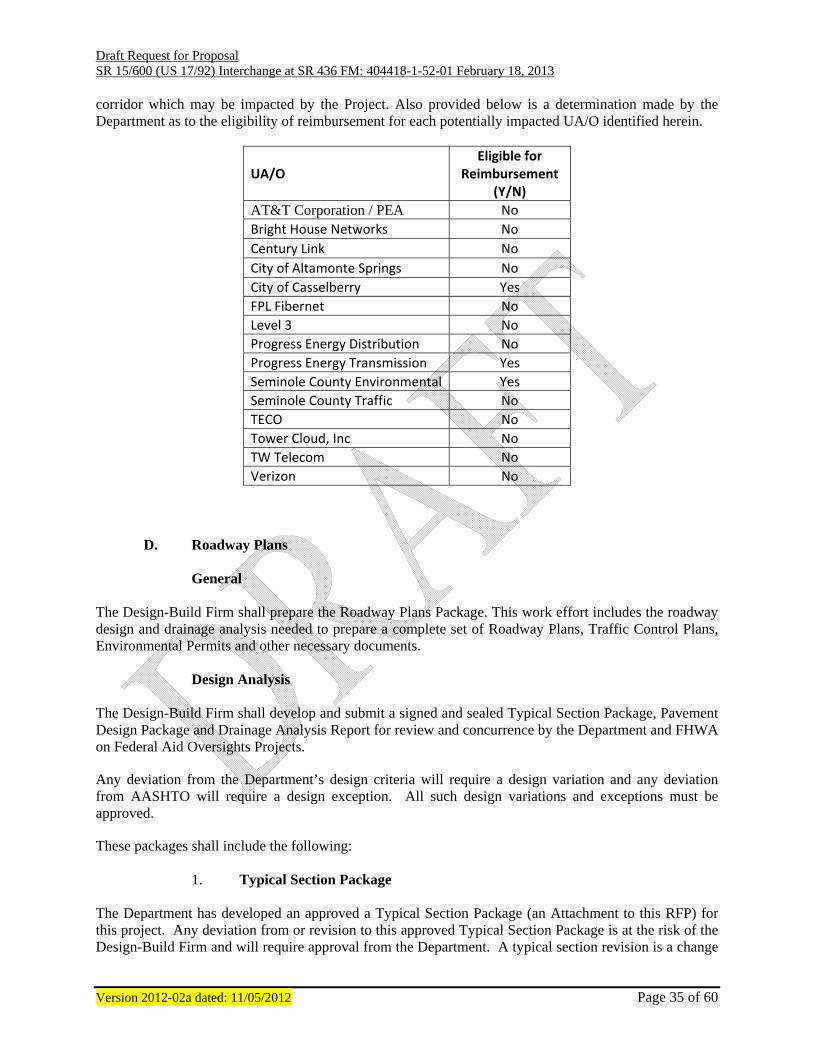
Draft Request for Proposal SR 15/600 (US 17/92) Interchange at SR 436 FM: 404418-1-52-01 February 18, 2013
Version 2012-02a dated: 11/05/2012 Page 35 of 60
corridor which may be impacted by the Project. Also provided below is a determination made by the Department as to the eligibility of reimbursement for each potentially impacted UA/O identified herein.
UA/O Eligible for
Reimbursement (Y/N)
AT&T Corporation / PEA No Bright House Networks No Century Link No City of Altamonte Springs No City of Casselberry Yes FPL Fibernet No Level 3 No Progress Energy Distribution No Progress Energy Transmission Yes Seminole County Environmental Yes Seminole County Traffic No TECO No Tower Cloud, Inc No TW Telecom No Verizon No
D. Roadway Plans
General
The Design-Build Firm shall prepare the Roadway Plans Package. This work effort includes the roadway design and drainage analysis needed to prepare a complete set of Roadway Plans, Traffic Control Plans, Environmental Permits and other necessary documents.
Design Analysis The Design-Build Firm shall develop and submit a signed and sealed Typical Section Package, Pavement Design Package and Drainage Analysis Report for review and concurrence by the Department and FHWA on Federal Aid Oversights Projects.
Any deviation from the Department’s design criteria will require a design variation and any deviation from AASHTO will require a design exception. All such design variations and exceptions must be approved.
These packages shall include the following:
1. Typical Section Package The Department has developed an approved a Typical Section Package (an Attachment to this RFP) for this project. Any deviation from or revision to this approved Typical Section Package is at the risk of the Design-Build Firm and will require approval from the Department. A typical section revision is a change
Draft Request for Proposal SR 15/600 (US 17/92) Interchange at SR 436 FM: 404418-1-52-01 February 18, 2013
Version 2012-02a dated: 11/05/2012 Page 36 of 60
to the requirements of the RFP.
2. Pavement Design Package
The Department has developed approved minimum pavement designs for asphalt pavements for use on this project. The minimum pavement designs are included as an Attachment to the RFP. Any modification of the pavement designs provided must be approved by the Department. Any modification is a change to the requirements of the RFP.
3. Drainage Analysis
The Design-Build Firm shall be responsible for designing the drainage and stormwater management systems. All design work shall be in compliance with the Department’s Drainage Manual; Florida Administrative Code, chapter 14-86; Federal Aid Policy Guide 23 CFR 650A; and the requirements of the regulatory agencies. This work will include the engineering analysis necessary to design any or all of the following: cross drains, French drains, roadway ditches, outfall ditches, storm sewers, retention/detention facilities, interchange drainage and water management, other drainage systems and elements of systems as required for a complete analysis. Full coordination with all permitting agencies, the district Environmental Management section and Drainage Design section will be required from the outset. Full documentation of all meetings and decisions are to be submitted to the District Drainage Design section. These activities and submittals should be coordinated through the Department’s Project Manager. The exact number of drainage basins, outfalls and water management facilities (retention/detention areas, weirs, etc.) will be the Design-Build Firm’s responsibility. No storm sewer pipe exiting a drainage structure shall be constructed with a flow line higher than any storm sewer pipe entering the same structure and all constructed inlets and manholes must have an outlet storm drain pipe. The objective is to obtain approved stormwater treatment/attenuation design. This service shall include, but is not limited to the following: Design of the conveyance system, treatment system, and attenuation system. Perform design and generate construction plans documenting the permitted systems function to criteria. The Design-Build Firm shall verify that all existing cross drains and storm sewers that are to remain have adequate hydraulic capacity and design life. Flood flow requirements will be determined in accordance with the Department’s procedures. If any of these existing cross drains or storm sewers are found to be hydraulically inadequate or found to have insufficient design life, they must be replaced or supplemented in accordance with the drainage requirements of this RFP. If any existing cross drains or storm sewers require repairs but otherwise would have sufficient remaining design life, repairs shall be made in accordance with the requirements of this RFP. All existing cross drains and storm sewer pipes that fall within the limits of a Mechanically Stabilized Earth (MSE) walls shall be replaced. Furthermore, storm drain systems constructed between mechanically stabilized earth (MSE) walls must be installed per the left side of Figure 4-1 or Figure 4-2 in Section 4.1.1 of the FDOT Storm Drain Handbook or be constructed per Figure 4-3 in Section 4.1.1 of the FDOT Storm Drain Handbook.

Draft Request for Proposal SR 15/600 (US 17/92) Interchange at SR 436 FM: 404418-1-52-01 February 18, 2013
Version 2012-02a dated: 11/05/2012 Page 37 of 60
The most downstream pipe of each storm drain system must be constructed with its outlet flow line at the toe of slope of any ditch or dry pond and the outlet top of pipe must be below the dry season water line of any wet pond. Trapezoidal weirs (i.e. weirs constructed in pond berms) shall not be used as pond control structures. No component of a final constructed permanent stormwater system shall be controlled by a pump or any other mechanical means.
The Design-Build Firm will consider optional culvert materials in accordance with the Department’s Drainage Manual Criteria. Prior to proceeding with the Drainage Design, the Design-Build Firm shall meet with the District Drainage Engineer. The purpose of this meeting is to provide information to the Design-Build Firm that will better coordinate the Preliminary and Final Drainage Design efforts. This meeting is mandatory and is to occur fifteen (15) calendar days (excluding weekends and Department observed holidays) prior to any submittals containing drainage components. The Design-Build Firm shall provide the Department’s District Drainage Engineer a signed and sealed Drainage Design Report and a copy of this report in PDF format on CD. It shall be a record set of all drainage computations, both hydrologic and hydraulic. The engineer shall include all necessary support data.
E. Geometric The Design-Build Firm shall design the geometric for the Project using the design standards that are most appropriate with proper consideration given to the design traffic volumes, adjacent land use, design consistency, aesthetics, ADA requirements, and this document. The design elements shall include, but not be limited to, the horizontal and vertical alignments, lane widths, shoulder widths, median widths, cross slopes, borders, sight distance, side slopes, front slopes and ditches. The geometric design developed by the Design-Build Firm shall be an engineering solution that is not merely an adherence to the minimum AASHTO and/or Department standards.
1. Geometric Criteria
The following table shows the minimum turn lane lengths and minimum number turn lanes in each direction:
Direction (NB, SB,
WB, EB) Min. Number of
LT Lanes *Min. Length of LT
Lane (FT) Min. Number of
RT Lanes *Min. Length of RT Lane (FT)
SR 15/600
NB 2 752 1 843
SB 3 596 1 470
SR 436
WB 3 546 1 677
EB 2 match existing 1 match existing *Note the length of the turn lanes includes the length of the taper.
Draft Request for Proposal SR 15/600 (US 17/92) Interchange at SR 436 FM: 404418-1-52-01 February 18, 2013
Version 2012-02a dated: 11/05/2012 Page 38 of 60
The dedicated U-Turn lanes located under the bridge shall use WB-62FL as the minimum design
vehicle.
F. Design Documentation, Computations and Quantities The Design-Build Firm shall submit to the Department design notes and computations to document the design conclusions reached during the development of the construction plans. The design notes and computation sheets shall be fully titled, numbered, dated, indexed, and signed by the designer and the checker. Computer output forms and other oversized sheets shall be folded to a standard size 8½" x 11". The data shall be in a hard-back folder for submittal to the Department. At the Project completion, a final set of design notes and computations, signed by the Design-Build Firm, shall be submitted with the record set of plans and tracings. The design notes and calculations shall include, but not be limited to the following data:
1. Design standards used for the Project
2. Geometric design calculations for horizontal alignments
3. Vertical geometry calculations
4. Documentation of decisions reached resulting from meetings, telephone conversations or site visits
5. Final quantities list
G. Structure Plans
1. Bridge Design Analysis
a. The Design-Build Firm shall submit to the Department final signed and
sealed design documentation prepared during the development of the plans.
b. The Design-Build Firm shall insure that the final geotechnical and
hydraulic recommendations and reports required for bridge design are submitted with the 90% bridge plans.
c. The Design-Build Firm shall "Load Rate" all bridges in accordance with
the Department Procedure 850-010-035 and the Structures Manual. The bridge load rating shall be submitted to the Department for review with the 90% superstructure submittal. The as-bid load rating (based on the 90% design plans) shall be provided to the Department before any traffic is placed on the bridge. The as-bid load rating shall be signed and sealed by a Professional Engineer licensed in the State of Florida. A final, signed and sealed copy of the Bridge Load Rating, updated for the as-built conditions shall be submitted to the Department’s Project Representative and the District Structures Maintenance Engineer with the as-built bridge plans.
Draft Request for Proposal SR 15/600 (US 17/92) Interchange at SR 436 FM: 404418-1-52-01 February 18, 2013
Version 2012-02a dated: 11/05/2012 Page 39 of 60
d. The Design-Build Firm shall evaluate scour on all bridges over water
using the procedures described in HEC 18. e. Any erection, demolition, and any proposed sheeting and/or shoring
plans that may potentially impact the railroad must be submitted to and approved by the railroad. This applies to areas adjacent to, within and over railroad rights of ways.
f. The Engineer of Record for bridges shall analyze the effects of the
construction related loads on the permanent structure. These effects include but are not limited to: construction equipment loads, change in segment length, change in construction sequence, etc. The Engineer of Record shall review all specialty engineer submittals (camber curves, falseworks systems, etc.) to ensure compliance with the contract plan requirements and intent.
2. Criteria
The Design-Build Firm shall incorporate the following into the design of this facility:
a. All plans and designs are to be prepared in accordance with AASHTO LRFD Bridge Design Specifications, Department Standard Specifications, Structures Manual, Plans Preparation Manual, Department Standard Drawings, Supplemental Specifications, Special Provisions, and directions from the State Structures Design Engineer, Temporary Design Bulletins, Structures Design Office and / or District Structures Design Engineer.
b. Critical Temporary Retaining Walls: Whenever the construction of a
structural component (such as a wall, footing, or other such component) requires excavation that may endanger the public or an existing structure that is in use the Design-Build Firm must protect the existing facility and the public. If a critical temporary retaining wall is, therefore, required during the construction stage only, it may be removed and reused after completion of the work. Such systems as steel sheet pilings, soldier beams and lagging or other similar systems are commonly used. In such cases, the Design-Build Firm is responsible for designing detailing the wall in the set of contract plans. These plans must be signed and sealed by the Structural Engineer in responsible charge of the wall design.
c. Non-sacrificial Anti-Graffiti coat shall be applied to the exposed surfaces
of the proprietary retaining walls and on the sides of the piers to a height of 12 feet above the finished ground.
d. The Design-Build Firm shall provide two 2-inch diameter utility conduits
in both fascia barrier of each bridge in accordance with FDOT standards.
H. Specifications Department Specifications may not be modified or revised. The Design-Build Firm shall also include all

Draft Request for Proposal SR 15/600 (US 17/92) Interchange at SR 436 FM: 404418-1-52-01 February 18, 2013
Version 2012-02a dated: 11/05/2012 Page 40 of 60
Technical Special Provisions, which will apply to the work in the proposal. Technical Special Provisions shall be written only for items not addressed by Department Specifications, and shall not be used as a means of changing Department Specifications. Before construction activities can begin, the Design-Build Firm shall prepare and submit a signed and sealed Construction Specifications Package for the Project, containing all applicable Division II and III Special Provisions and Supplemental Specifications from the Specifications Workbook in effect at the time the Bid Price Proposals were due in the District Office. The Specifications Package shall be prepared, signed and sealed by the Design-Build Firms Engineer of Record who has successfully completed the mandatory Specifications Package Preparations Training. The website for completing the training is at the following URL address: http://www2.dot.state.fl.us/SpecificationsEstimates/PackagePreparation/TrainingConsultants.aspx Specification Workbooks are posted on the Department’s website at the following URL address: https://www2.dot.state.fl.us/SpecificationsPackage/Utilities/Membership/login.aspx?ReturnUrl=%2fspecificationspackage%2fDefault.aspx. The signed and sealed Specifications Package shall also include individually signed and sealed Technical Special Provisions for any and all work not addressed by Department Specifications. Any Technical Special Provisions included in the signed and sealed Construction Specifications Package which had not been included in the proposal phase, may require a contract cost modification as a condition of approval. Upon review by the Department, the Construction Specifications Package will be stamped “Released for Construction” and initialed and dated by the reviewer. Any subsequent modifications to the Construction Specifications Package shall be prepared, signed and sealed as a Supplemental Specifications Package, subject to the same process for submittal, review, and, release for construction, as described above, for the original Construction Specifications Package. Construction work affected by Supplemental Specifications Packages shall not begin until stamped “Released for Construction” Supplemental Specification Package is obtained.
I. Shop Drawings
The Design-Build Firm shall be responsible for the preparation and approval of all Shop Drawings. Shop Drawings shall be in conformance with the Departments Plans Preparation Manual when submitted to the Department and shall bear the stamp and signature of the Design-Build Firm’s Engineer of Record (EOR), and Specialty Engineer, as appropriate. The Department shall review the Shop Drawing(s) to evaluate compliance with Project requirements and provide any findings to the Design-Build Firm. The Departments procedural review of shop drawings is to assure that the Design-Build Firm’s EOR has approved and signed the drawing, the drawing has been independently reviewed and is in general conformance with the plans. The Departments review is not meant to be a complete and detailed review. Upon review of the shop drawing, the Department will stamp “Released for Construction” or “Released for Construction as noted” and initialed and dated by the reviewer. Shop Drawing submittals must be accompanied by sufficient information for adjoining components or areas of work to allow for proper evaluation of the Shop Drawing(s) submitted for review.
J. Sequence of Construction

Draft Request for Proposal SR 15/600 (US 17/92) Interchange at SR 436 FM: 404418-1-52-01 February 18, 2013
Version 2012-02a dated: 11/05/2012 Page 41 of 60
The Design-Build Firm shall construct the work in a logical manner and with the following objectives as guides:
1. Maintain or improve, to the maximum extent possible, the quality of existing traffic operations, both in terms of flow rate and safety, throughout the duration of the Project.
2. Minimize the number of different Traffic Control Plan (TCP) phases, i.e., number of
different diversions and detours for a given traffic movement.
3. Take advantage of newly constructed portions of the permanent facility as soon as possible when it is in the best interest of traffic operations and construction activity.
4. Maintain reasonable direct access to adjacent properties at all times, with the exception in
areas of limited access right-of-way where direct access is not permitted.
5. Proper coordination with adjacent construction Projects and maintaining agencies.
K. Stormwater Pollution Prevention Plans (SWPPP) The Design-Build Firm shall prepare a Storm Water Pollution Prevention Plan (SWPPP) as required by the National Pollution Discharge Elimination System (NPDES). The Design-Build Firm shall refer to the PPM and Florida Department of Environmental Protection (FDEP) Rule 62-621.300(4)(a) for information in regard to the SWPPP. This SWPPP shall be submitted along with the Design-Build Firm’s Certification (FDEP Form 62-621.300(4)(b) NOTICE OF INTENT (NOI) TO USE GENERIC PERMIT FOR STORMWATER DISCHARGE FROM LARGE AND SMALL CONSTRUCTION ACTIVITIES) at least 15 calendar days (excluding Holidays as defined in Section 1-3 of the Specifications) prior to beginning construction activities.
L. Temporary Traffic Control Plan
1. Traffic Control Analysis
The Design-Build Firm shall design a safe and effective Temporary Traffic Control Plan to move vehicular traffic during all phases of construction. The areas shall include, but are not limited to, construction phasing, utility relocation, drainage structures, signalization, ditches, front slopes, back slopes, drop offs within clear zone, and traffic monitoring sites. Special consideration shall be given to the drainage system when developing the construction phases. Positive drainage must be maintained at all times. The Temporary Traffic Control Plan shall address how to assist with maintenance of traffic throughout the duration of the contract. The Temporary Traffic Control Plan shall be prepared by a certified designer who has completed the Department’s training course, and in accordance with the Department’s Design Standards and the Roadway Plans Preparation Manual. Transportation Management Plans (TMPs) are required for significant Projects which are defined as:
1. A Project that, alone or in combination with other concurrent Projects nearby, is anticipated to cause sustained work zone impacts.

Draft Request for Proposal SR 15/600 (US 17/92) Interchange at SR 436 FM: 404418-1-52-01 February 18, 2013
Version 2012-02a dated: 11/05/2012 Page 42 of 60
2. All Interstate system Projects within the boundaries of a designated
Transportation Management Area (TMA) that occupy a location for more than three days with either intermittent or continuous lane closures shall be considered as significant Projects.
For significant Projects a TMP will consist of three components:
1. Temporary Traffic Control (TTC) plan component;
2. Transportation Operations (TO) component; and
3. Public Information (PI) component Additional information can be found in Volume I Chapter 10 of the PPM. The Design-Build Firm shall notify Les Brown with Lynx Transit at (407) 841-2279, ext. 3503, 2 weeks prior to scheduled relocation of bus stop signs and bus benches. The Department has made available a parcel on SR 15/600 for the purpose of construction staging. This parcel is located at Sta. 445+60 LT and is called out in Phase 1A of the concept Traffic Control Plans.
2. Temporary Traffic Control Plans:
The Design-Build Firm shall utilize Index Series 600 of the Department’s Design Standards where applicable. Should these standards be inadequate, a detailed Temporary Traffic Control Plan shall be developed. The Design-Build Firm shall prepare plan sheets, notes, and details to include the following: typical section sheet(s), general notes and construction sequence sheet(s), typical detail sheet(s), traffic control plan sheet(s).
The Design-Build Firm shall prepare additional plan sheets such as cross sections, profiles, drainage structures, retaining wall details, and sheet piling as necessary for proper construction and implementation of the Temporary Traffic Control Plan. The Temporary Traffic Control Drawings for any Release for Construction component set shall depict how traffic will be maintained in the conjunction with previous, subsequent, an adjacent Release for Construction component sets. In the event permanent vehicle detection is disrupted, the contractor shall provide an alternative means of detection to all lanes approaching the intersection, separating each movement which previously had detection. The type of detector shall be approved by the Engineer prior to installation. Equipment shall only detect the intended movement.
3. Traffic Control Restrictions
There will be NO LANE CLOSURES ALLOWED on SR 15/600 (US 17/92) and SR 436 between the hours of 6:00 AM to 11:00 PM. A lane may only be closed during active work periods. Rolling barricades will be allowed during the approved lane closure hours. All lane closures, including ramp closures, must be reported to the local emergency agencies, the media and the District Five public information officer (Steve Olson 386-943-5479). Also, the Design-Build Firm shall develop the Project to be able to provide for all lanes of traffic to be open in the event of an emergency or if the lane closure causes a driver delay greater than 20 minutes.

Draft Request for Proposal SR 15/600 (US 17/92) Interchange at SR 436 FM: 404418-1-52-01 February 18, 2013
Version 2012-02a dated: 11/05/2012 Page 43 of 60
Existing posted speed limits must be maintained during construction unless otherwise approved by the Department. The Design-Build Firm shall provide a minimum of seven (7) calendar days notice to the motoring public of all lane closures. The Design-Build Firm shall maintain three through lanes and all existing left turn lanes during all phases of traffic control. Intermittent short term closures are allowable during off-peak hours for construction activities. During all phases of traffic control the Design-Build Firm shall maintain the widest possible lane widths up to 12 feet but under no circumstances shall the lanes widths be less than 10 feet (including but not limited to through lanes, turn lanes, ramps and auxiliary lanes).
4. Pedestrian and Bicycle Access The Design-Build Firm shall provide ADA compliant pedestrian and bicycle access at all times. This access shall include the required FDOT maintenance of pedestrian traffic signing, the relocation of transit facility assets and deployment of temporary safety devices as required to ensure safe, seamless, system connections. Coordinate with the local transit agencies at least 2 weeks prior to relocating any transit facility asset. The Design-Build Firm shall maintain safe pedestrian access to bus stops at all times.
M. Environmental Services/Permits/Mitigation The Design-Build Firm will be responsible for preparing designs and proposing construction methods that are permitable. The Design-Build Firm will be responsible for any required permit fees. All permits required for a particular construction activity will be acquired prior to commencing the particular construction activity. Delays due to incomplete permit packages, agency rejection, agency denials, agency processing time, or any permit violations, except as provided herein, will be the responsibility of the Design-Build Firm, and will not be considered sufficient reason for time extension. As the permitee, FDOT is responsible for reviewing, approving, signing, and submitting the permit application package including all permit modifications, or subsequent permit applications. If, as a result of design changes proposed by the Design-Build Firm, additional environmental mitigation is required, it shall be the responsibility of the Design-Build Firm to pay for the mitigation. The Design-Build Firm shall be responsible for an assessment of all potential gopher tortoise habitats that could be impacted by the Project. The Department must verify the completeness and accuracy of the assessment. The habitat will be systematically surveyed according to the current guidelines published by the Florida Fish and Wildlife Conservation Commission (FWC). If gopher tortoise burrows are found, all practicable measures will be employed to avoid impacts. The Design-Build Firm shall be responsible for preparing required documentation for the Department to obtain a FWC permit for the relocation of gopher tortoises and commensals from burrows which cannot be avoided. A copy of the permit and any subsequent reports to FWC must be provided to the District Environmental Management Office. The Design-Build Firm will be required to pay all permit fees including any and all fees associated with the relocation of gopher tortoises. Any fines levied by permitting agencies shall be the responsibility of the Design-Build Firm. The following Project specific Environmental Services/Permits have been identified as specific requirements for this project:

Draft Request for Proposal SR 15/600 (US 17/92) Interchange at SR 436 FM: 404418-1-52-01 February 18, 2013
Version 2012-02a dated: 11/05/2012 Page 44 of 60
1. Contaminated Materials
Unless specifically identified otherwise, the design and construction of any alternate design approach identified within this RFP is not a requirement of this RFP. The Design-Build Firm is not responsible for any permitting or commenting agency coordination or other impacts to the permit processes that would be associated with any alternate design approach, unless the Design-Build Firm chooses to include the alternate design approach in its Proposal.
N. Signing and Pavement Marking Plans The Design-Build Firm shall prepare signing and pavement marking plans in accordance with Department criteria. Pavement Marking Criteria
Special emphasis crosswalks shall be provided at all signalized intersections.
The final pavement markings shall be paint.
Signing Criteria All signs within the project limits (SR 15/600 Sta. 419+00 to Sta. 465+30 and SR 436 Sta. 412+15 to Sta. 437+20) shall be replaced. Any removed signs that are the property of Seminole County shall be returned to the County. The Design-Build Firm shall coordinate with the City of Casselberry and Seminole County regarding sign details for street name signs within the Casselberry city limits and follow the maintaining agencies design criteria/standards. For all overhead signs (cantilever or truss mounted) the Design-Build Firm shall either light the signs or use super-high efficiency reflective sheeting. The choice between the two installations is up to the Design-Build Firm however only one system may be used within the project. All overhead signs will be lighted or all overhead signs will have the sheeting. The super-high efficiency reflective sheeting will meet or exceed the specifications shown in the table below. The Design-Build Firm shall provide the technical specification for the product in the Technical Proposal.
MINIMUM REFLECTIVE INTENSITY VALUES FOR
RETROREFLECTIVE SHEETING ON OVERHEAD SIGNS WITHOUT LIGHTING
Minimum Coefficient of Retroreflection·(RA) cd/(lx · m2)
Per ASTM E-810 (Average of 0 and 90 degree orientation)

Draft Request for Proposal SR 15/600 (US 17/92) Interchange at SR 436 FM: 404418-1-52-01 February 18, 2013
Version 2012-02a dated: 11/05/2012 Page 45 of 60
Observation
Angle°
Entrance
Angle° White Yellow Fluor. Yellow
Fluor. Yellow-
Green Red Green Blue
Fluor.
Orange
0.2 -4 570 425 340 455 114 57 45 200
0.2 30 215 160 130 170 43 21 28 75
0.2 40 100 75 60 80 20 10 7.5 35
0.5 -4 400 300 240 320 80 40 32 140
0.5 30 150 112 90 120 30 15 16 52
0.5 40 50 37 30 40 10 5 4 18
1 -4 120 90 72 96 24 12 9 42
1 30 45 34 27 36 9 4.5 6 16
1 40 25 19 15 20 5 3 2 9 The lighting of the signs will meet Department criteria. The Design-Build Firm shall be responsible for the connection to the power source and the service through Final Acceptance.
O. Signalization Plans The Design-Build Firm shall prepare Signalization plans in accordance with Department criteria. The signal design, details and installation must be approved by the Department and shall meet the standards and specification of the Department. In addition, the local agencies have standards that must also be met. The Design-Build Firm shall coordinate with the City of Casselberry and Seminole County regarding their signalization standards and criteria. The following list of intersections will require design plans and construction/reconstruction of traffic signals:
1. SR 436 and Oxford Road (Sta. 415+00 +/-) (This signal is not shown in the concept plans and is an addition to the RFP)
2. SR 436 and Fern Park Plaza (Sta. 418+00 +/-)
3. SR 436 and SR 15/600 (US 17/92)
The following list of intersections will require the signals to be removed:
4. Fernwood Boulevard and SR 15/600 (US 17/92) 5. Live Oaks Boulevard and SR 15/600 (US 17/92)
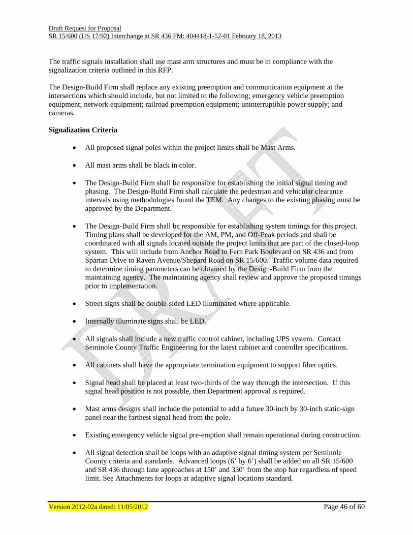
Draft Request for Proposal SR 15/600 (US 17/92) Interchange at SR 436 FM: 404418-1-52-01 February 18, 2013
Version 2012-02a dated: 11/05/2012 Page 46 of 60
The traffic signals installation shall use mast arm structures and must be in compliance with the signalization criteria outlined in this RFP. The Design-Build Firm shall replace any existing preemption and communication equipment at the intersections which should include, but not limited to the following; emergency vehicle preemption equipment; network equipment; railroad preemption equipment; uninterruptible power supply; and cameras. Signalization Criteria
All proposed signal poles within the project limits shall be Mast Arms.
All mast arms shall be black in color.
The Design-Build Firm shall be responsible for establishing the initial signal timing and phasing. The Design-Build Firm shall calculate the pedestrian and vehicular clearance intervals using methodologies found the TEM. Any changes to the existing phasing must be approved by the Department.
The Design-Build Firm shall be responsible for establishing system timings for this project.
Timing plans shall be developed for the AM, PM, and Off-Peak periods and shall be coordinated with all signals located outside the project limits that are part of the closed-loop system. This will include from Anchor Road to Fern Park Boulevard on SR 436 and from Spartan Drive to Raven Avenue/Shepard Road on SR 15/600. Traffic volume data required to determine timing parameters can be obtained by the Design-Build Firm from the maintaining agency. The maintaining agency shall review and approve the proposed timings prior to implementation.
Street signs shall be double-sided LED illuminated where applicable. Internally illuminate signs shall be LED. All signals shall include a new traffic control cabinet, including UPS system. Contact
Seminole County Traffic Engineering for the latest cabinet and controller specifications. All cabinets shall have the appropriate termination equipment to support fiber optics. Signal head shall be placed at least two-thirds of the way through the intersection. If this
signal head position is not possible, then Department approval is required. Mast arms designs shall include the potential to add a future 30-inch by 30-inch static-sign
panel near the farthest signal head from the pole. Existing emergency vehicle signal pre-emption shall remain operational during construction. All signal detection shall be loops with an adaptive signal timing system per Seminole
County criteria and standards. Advanced loops (6’ by 6’) shall be added on all SR 15/600 and SR 436 through lane approaches at 150’ and 330’ from the stop bar regardless of speed limit. See Attachments for loops at adaptive signal locations standard.

Draft Request for Proposal SR 15/600 (US 17/92) Interchange at SR 436 FM: 404418-1-52-01 February 18, 2013
Version 2012-02a dated: 11/05/2012 Page 47 of 60
All stop bar loops shall be 6’ by 20’ for all through movements on SR 436, SR 15/600, and
side street movements including main street left turns. The left turn phases shall run concurrently. New traffic signal heads shall be mounted vertically unless otherwise approved by the
Department. All new signals shall be interconnected with the existing signal both on SR 15/600 and SR
436. When a protected left turn phase is provided, the mast arms for single left turn lanes shall be
designed for 4-section signal heads (flashing yellow arrow). The 4-section signal head shall be centered in the left turn lane. If the signal head cannot be centered on the middle of the left turn lane, then approval from FDOT Traffic Operations and FDOT Construction Office is required. This criterion applies to both, side street and mainline left turn movements that are not controlled by dual left turn signal heads, opposing dual left turn movements, or are split-phased.
If a protected left turn phase is not provided, the mast arms shall be designed to accommodate
a future 4-section signal head. The design shall allow a placement so the head is positioned in the middle of the left turn lane.
Mast arm mounting heights shall be calculated for each specific structure. The designer shall
provide a mounting height that positioned the top of the yellow indication in line with the center of the mast arm. The distance over the highest point of the roadway and bottom of the signal head assembly (includes back plate) shall be 18 feet. If this distance cannot be achieved, coordinate with the FDOT Traffic Operations and FDOT Construction Office for approval.
Existing signal poles that are to be removed shall become the property of the Design/Build
Firm and shall be disposed of at a location provided by the Design/Build Firm. Existing signal pole foundations shall be removed completely. If complete removal is not
possible, approval from the Department is required for partial removal. The Design-Build Firm shall be responsible to coordinate with Utility companies for power
service and any necessary communications connections, and are responsible for all costs involved with this coordination.
All removed equipment, except for poles, shall be delivered to the local agency by the
Design-Build Firm. If the local agency refuses the equipment, then it shall be disposed of by the Design-Build Firm. Reasonable effort must be made to schedule delivery with the agency.
The Design-Build Firm shall develop and finalize the design of all temporary signalization
and shall submit the designs to the Department and to the corresponding local agency for review and concurrence prior to initiating any construction.

Draft Request for Proposal SR 15/600 (US 17/92) Interchange at SR 436 FM: 404418-1-52-01 February 18, 2013
Version 2012-02a dated: 11/05/2012 Page 48 of 60
The Design-Build Firm shall minimize all pedestrian crossings to reduce exposure. Pedestrian detection shall be provided under the bridge.
P. Access Management Plan
During the PD&E for this project an access management plans was developed for each alternative. The PD&E can be found in the Reference Documents of this RFP. An access management letter was submitted to FDOT during the roadway concept plans phase. The access management letter can be found in the Attachments of this RFP. In the access management plan FDOT has designated both SR 15/600 (US 17/92) and SR 436 with an Access Management Classification 5. The proposed improvements to the intersection of US 17/92 and SR 436 necessitate removing traffic signals at the intersections of US 17/92 with Fernwood Boulevard and Live Oaks Boulevard, respectively. The project will also close median openings on US 17/92 that currently align with the following: Division Street, Pine Street, and the Casselberry Exchange development. The construction of the bridge will allow only “right in-right out” movements at those intersections, with the exception of Division Street. The Design-Build Firm will adhere to the access management plan as described in the access management letter (located in the Attachments) and the access management plan located in the PD&E report. The Design-Build Firm shall ensure that the directional median opening design at Sunnytown Road physically discourages illegal left turns from Sunnytown and provides adequate width for northbound u-turns. Driveways shall be constructed as depicted in the concept plans unless otherwise approved by Traffic Operations.
Q. Lighting Plans The Design/Build Firm shall prepare lighting plans in accordance with Department criteria for the project limits on SR 15/600 from Ridge Road (approximate station 401+20) to Normandy Road (approximate station 466+70) and on SR 436 from Oxford Road (approximate station 411+90) to Anchor Road (approximate station 443+00). The Design/Build Firm will be responsible for the construction of the lighting for the entire length of the project. The Design/Build Firm shall be responsible for coordination with all of the applicable parties necessary for the design, construction and service connection of the project lighting. This coordination will include, but is not limited to, FDOT, City of Casselberry, Seminole County, and Progress Energy. All costs associated with the design and construction shall be the responsibility of the Design/Build Firm. The Design-Build Firm shall submit a Lighting Design Analysis Report including a point-by-point photometric analysis for both the roadway and sign lighting to the Department for review and approval. The Design-Build Firm shall submit a Lighting Design Analysis Report including a point-by-point photometric analysis for both the roadway and sign lighting to the Department for review and approval. Lighting shall be, as a minimum, standard FDOT conventional roadway lighting.
R. ITS
ITS concept plans are not available for the project. However, there are existing ITS facilities within the project corridor. The Design-Build Firm shall be responsible for maintaining the existing system and coordinating with the FDOT, Seminole County and the City of Casselberry to deliver a final product that is equal to or better than the existing system and fully adheres to the FDOT, Seminole County and the City of Casselberry design and construction standards and criteria. All existing ITS facilities shall be maintained throughout the entire construction process. Maintain Existing Fiber Optic Cable (Arterial Trunklines and Drops)

Draft Request for Proposal SR 15/600 (US 17/92) Interchange at SR 436 FM: 404418-1-52-01 February 18, 2013
Version 2012-02a dated: 11/05/2012 Page 49 of 60
The Design-Build Firm shall maintain all existing District 5 and Seminole County fiber optic cables within the project limits for the duration of the project. The Design-Build firm shall be responsible for rerouting the fiber optic communication cable(s) if necessary in order to avoid any potential impact(s) due to the roadway project. Slack fiber optic cable in all splice vaults and pull boxes is required for maintenance use and must be maintained. Slack fiber may not be utilized by the Design-Build Firm Design-Build Firm in an effort to reroute communications or to avoid installation of new fiber optic cable. Any and all splices to the fiber optic cable shall be fusion splices. Maintain Existing Fiber Optic Communications The Design-Build Firm shall maintain the existing District 5 and Seminole County fiber optic communications within the project limits for the duration of the project. These communications include the connection of the existing Automatic Vehicle Identification (AVI) readers, Arterial Dynamic Message Signs (ADMS), and Closed Circuit Television (CCTV) to the Fiber Optic Network(s) as well as the communications that pass through the project limits. Maintain/Relocate Existing Arterial Dynamic Message Signs and Structures The Design-Build Firm shall maintain the existing District 5 Arterial Dynamic Message signs (ADMS) within the project limits, including the communication connection between the ADMS and the Seminole County Camelon Software. The Design-Build Firm shall be responsible for relocating the ADMS signs and structures, including the construction of new foundations, as necessary in order to avoid any potential impact due to the roadway project. The locations of relocated ADMS must remain outside clear zone and require Department approval. Maintain/Relocate Existing Closed Circuit Television The Design-Build Firm shall maintain the existing Closed Circuit Television (CCTV) within the project limits, including the communication connection between the CCTV and network. The Design-Build Firm shall be responsible for relocating the CCTV, including the mounting hardware and cabling, as necessary in order to avoid any potential impact due to the roadway project. The location of relocated CCTV must provide complete coverage of the intersection and optimal coverage of US 17/92 and SR 436 in all directions. The location of the relocated CCTV requires Department approval. Maintain/Relocate Existing ITS Power Services The Design-Build Firm shall maintain existing ITS power services including power service disconnects, power service poles, wiring, conduit, and transformers. The Design-Build Firm shall be responsible for relocating the power services, or coordinating new power services, as necessary in order to power newly relocated devices or to avoid any potential impact due to the roadway project. ITS Device Testing The Design-Build Firm shall perform the following ITS tests on all relocated and new ITS devices including but not limited to the ADMS, AVI, and CCTV. Specifically, the Design-Build Firm shall perform the Installed Site Testing, System Testing, and Operational Testing as detailed in the FDOT Specifications 781-3.19, 781-3.20, and 781-3.21 for any and all relocated ADMS. The relocated CCTV shall be subject to the testing detailed in FDOT Specification 782-1.4.2. Proposed AVI shall be required to be tested as outlined in Section 786. Maintain Existing AVI

Draft Request for Proposal SR 15/600 (US 17/92) Interchange at SR 436 FM: 404418-1-52-01 February 18, 2013
Version 2012-02a dated: 11/05/2012 Page 50 of 60
The Design-Build Firm shall maintain the existing District 5 Intelligent Transportation System (ITS) Automatic Vehicle Identification (AVI) data collection system located at the intersection of US17-92 and SR 436. The Design-Build Firm can relocate the AVI in such a way as to maintain the function of the device. The number of reads and accuracy of the travel times generated shall be maintained throughout construction. Additional Data Collection Units and/or Data Collection Sites may be necessary. The Design-Build Firm shall receive Department approval of 2 weeks prior to relocating the devices through the submission of Maintenance of Communication (MOC) Plans. It is suggested to have a coordination meeting with D5 FDOT ITS Staff to determine IP scheme and Sunguide implications prior to submitting MOC plans. A Maintenance of Communication Plan shall include:
A scheme for physical relocation of the devices IP addresses for all devices being modified Sunguide modifications to be completed by D5 FDOT ITS Staff Timeline for changes Expected Downtime
An AVI Data Collection Site (DCS) shall be defined as a location in which all data collection units at a single intersection, detecting multiple approaches, are tied to or synchronized as a single control point to provide vehicle detection and data collection of that intersection or area. A Data Collection Unit (DCU) shall be defined as the combination of an RF Reader/Module, Controller and antenna(s) installed at an AVI DCS site with the functionality of reading and collecting data from toll transponders in multiple lanes at only one approach of an intersection. The corridors in which AVI DCSs are located and shall be removed and replaced are listed below. All DCUs shall communicate with Regional Traffic Management Center (RTMC) Replace Existing AVI The Design-Build Firm shall provide the Department of Transportation (Department) with new AVI vehicle detection and data collection equipment along with associated components to at US17-92 and SR 436 to maintain the functionality of the District 5 Intelligent Transportation System (ITS) Automatic Vehicle Identification (AVI) data collection system. The Design-Build Firm shall replace the existing equipment with new equipment after all relocations for the purpose of MOC have been complete. The scope of work for this contract includes all parts, labor and services for the complete installation of a fully functional AVI data collection system to include the ability to generate travel times. The newly installed AVI Data Collection Units (DCU) must be fully compatible with the Department’s central control software system (Sunguide). AVI Functional Requirements The DCU Field Equipment shall detect vehicles carrying the appropriate tags and shall provide real time vehicle information to the RTMC. As many as three (3) lanes of traffic in each direction shall be monitored. The DCU Field Equipment shall be capable of differentiating the transponders in tailgating or shadowing vehicles, assuming that the transponder in the second vehicle is “visible” to the antenna.
Draft Request for Proposal SR 15/600 (US 17/92) Interchange at SR 436 FM: 404418-1-52-01 February 18, 2013
Version 2012-02a dated: 11/05/2012 Page 51 of 60
The DCU data shall be compatible with the Department’s Sunguide Software. The DCUs shall be configured to send messages to Sunguide via an Ethernet communication interface. Each message sent to Sunguide shall include:
A start of message indicator. A message sequence number to allow detection of missed messages. A message type field (e.g., a tag read and a set time confirmation message would be different
types). A message size indicator if the message size is not fixed for a message type (e.g., two messages of the same type, such as two tag read messages, could have different message sizes).
A data field or fields containing the body of the message. Error-checking data to include a minimum of a 16-bit checksum.
The DCU shall send tag reads to Sunguide as the reads occur. The body of each tag read message shall include:
The transponder ID and/or other tag identification information that was read from the AVI transponder.
A timestamp indicating when the read occurred. Timestamps used in tag read messages and in any other messages to or from the DCU shall include:
year month day hour minute second
The timestamp may be sent as one aggregate value, such as seconds since 1900, provided all of the information above can be extracted from the aggregate value. DCU – Tag Interface This section describes requirements for the interface between the DCUs and AVI Tags.
The DCU shall read the Caltrans Title 21 ID from Type II and Type III transponder tags. The DCU shall read the ISO18000-6B ID from mini sticker tags.
The DCU shall perform an AVI tag read without activating the transponder’s buzzer circuit (i.e., without causing the tag to make an audible sound) or activating any LEDs on the transponder. The DCU shall not activate the “sleep mode” function on the tags.
Maintain Existing Communications Master Hub (Seminole County) The Design Build Firm shall maintain the existing Seminole County Master Communications hub located within the project limits (Northeast Corner US 17-92 / SR 436). The Design Build firm shall be responsible for keeping the climate controlled hub and interior equipment on line with all links operational throughout the project. The Design Build firm shall be responsible for protecting the communications hub from damage through construction. This includes damage to the cabinet in the form of dents, excessive dirt, or damage to the air conditioning system. If damage occurs to the hub cabinet or its components, then the Design Build Firm shall be responsible for the replacement of damaged or affected components including but not limited to the air conditioner and the network switch.

Draft Request for Proposal SR 15/600 (US 17/92) Interchange at SR 436 FM: 404418-1-52-01 February 18, 2013
Version 2012-02a dated: 11/05/2012 Page 52 of 60
S. Utilities
As part of this design build project, the City of Casselberry has developed construction plans for water and sewer improvements within the project limits. Those plans are part of this project and are located in the Attachments section of this RFP. The construction will be performed by the Design-Build Firm. The Design-Build Firm shall follow the City of Casselberry design standards, criteria and specifications for the construction of the water and sewer facilities. The specifications can be found in the Attachments of this RFP. These specifications only apply to the City of Casselberry water and sewer facilities.
T. Aesthetics and Landscape
The City of Casselberry has installed landscaping on several vacant parcels within the project right-of-way limits. The following locations include but are not limited to parcels 100, 101, 103, 107, and in the existing medians of US 17/92. The City intends to relocate the desired landscaping prior to the start of construction. It is the responsibility of the Design-Build Firm to coordinate with the City of Casselberry Public Works Department and FDOT to confirm the desired landscaping has been relocated or will be relocated prior to the start of construction. The Design-Build Firm shall include the following plants in their landscaping design. The plant list can also be found in the landscaping concept plans (Reference Documents of this RFP). SYM. Description Installed Size Unit Total
SMALL PLANTS IVN Ilex bomitoria 'Nana' (Dwarf Youpon) 3 Gal., 12"-18", 24" O.C., Full EA 1,048
RI Rhaphiolepis indica "Alba" (Indian Hawthorne)
3 Gal., 18"-24", 24" O.C., Full EA 14,589
RK Rosa Knockout Red (Knockout Rose) 3 Gal., 18"-24", 30" O.C., Full EA 2,681 RE Russelia equisetiformis (Firecracker Plant) 1 Gal., 18"-24", 30" O.C., Full EA 288
SB Spartina bakeri (Sand Cordgrass) 1 Gal., 18"-20" Ht. Min., 36" O.C., Full
EA 1,543
TA Trachelospermum asiaticum 'Minima' (Minima Jasmine)
1 Gal., 5-6 ppp, runners 10-12" Min., 24" O.C.
EA 12,334
FGD Tripsacum floridana (Dwarf Fakahatchee Grass)
1 Gal., 12"-15" Ht. Min., 30" O.C., Full
EA 329
VS Viburnum suspensum (Sandankwa viburnum)
3 Gal., 12"x24", 30" O.C., Full EA 1,506
VO Viburnum obovatum (Mrs. Schiller's Delight)
3 Gal., 18" Ht. Min., 30" O.C., Full
EA 1,017
ZP Zamia pumila (Coontie) 3 Gal., 12"-16", 30" O.C. EA 1,239 LARGE PLANTS
AR Acer rubrum 'Florida Flame' (Red Maple) 15 Gal., 8'-9' Ht. Full Spread EA 18 CS Cupressus sempervirens (Italian Cypress) 45 Gal., 10'-12', Full EA 18 IV Ilex vomitoria 'Will Flemings' 15 Gal., 4'-5', Full EA 31
LI Lagerstroemia 'Natchez' (Crape Myrtle) 65 Gal., 12'x5' STD, 3"-3 1/2" cal.
EA 183
MG Magnolia grandiflora (Little Gem) 30 Gal., 7'-8'x4'-5', 2" Cal., Full, Matched Specimens
EA 25
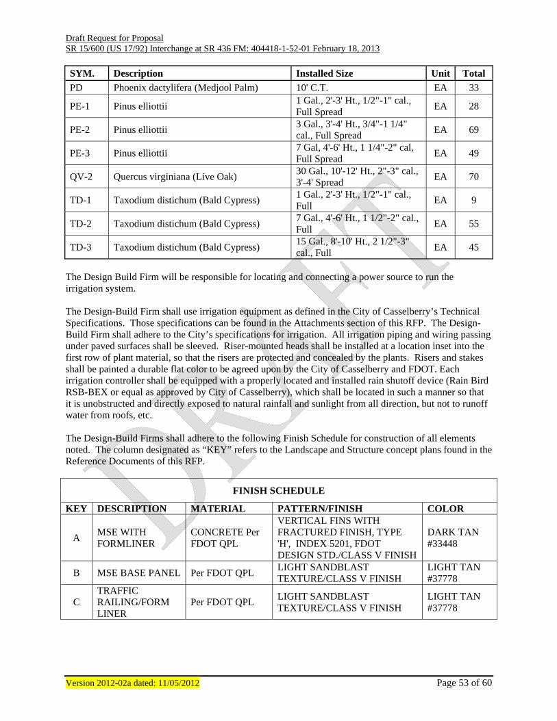
Draft Request for Proposal SR 15/600 (US 17/92) Interchange at SR 436 FM: 404418-1-52-01 February 18, 2013
Version 2012-02a dated: 11/05/2012 Page 53 of 60
SYM. Description Installed Size Unit Total
PD Phoenix dactylifera (Medjool Palm) 10' C.T. EA 33
PE-1 Pinus elliottii 1 Gal., 2'-3' Ht., 1/2"-1" cal., Full Spread
EA 28
PE-2 Pinus elliottii 3 Gal., 3'-4' Ht., 3/4"-1 1/4" cal., Full Spread
EA 69
PE-3 Pinus elliottii 7 Gal, 4'-6' Ht., 1 1/4"-2" cal, Full Spread
EA 49
QV-2 Quercus virginiana (Live Oak) 30 Gal., 10'-12' Ht., 2"-3" cal., 3'-4' Spread
EA 70
TD-1 Taxodium distichum (Bald Cypress) 1 Gal., 2'-3' Ht., 1/2"-1" cal., Full
EA 9
TD-2 Taxodium distichum (Bald Cypress) 7 Gal., 4'-6' Ht., 1 1/2"-2" cal., Full
EA 55
TD-3 Taxodium distichum (Bald Cypress) 15 Gal., 8'-10' Ht., 2 1/2"-3" cal., Full
EA 45
The Design Build Firm will be responsible for locating and connecting a power source to run the irrigation system. The Design-Build Firm shall use irrigation equipment as defined in the City of Casselberry’s Technical Specifications. Those specifications can be found in the Attachments section of this RFP. The Design-Build Firm shall adhere to the City’s specifications for irrigation. All irrigation piping and wiring passing under paved surfaces shall be sleeved. Riser-mounted heads shall be installed at a location inset into the first row of plant material, so that the risers are protected and concealed by the plants. Risers and stakes shall be painted a durable flat color to be agreed upon by the City of Casselberry and FDOT. Each irrigation controller shall be equipped with a properly located and installed rain shutoff device (Rain Bird RSB-BEX or equal as approved by City of Casselberry), which shall be located in such a manner so that it is unobstructed and directly exposed to natural rainfall and sunlight from all direction, but not to runoff water from roofs, etc. The Design-Build Firms shall adhere to the following Finish Schedule for construction of all elements noted. The column designated as “KEY” refers to the Landscape and Structure concept plans found in the Reference Documents of this RFP.
FINISH SCHEDULE
KEY DESCRIPTION MATERIAL PATTERN/FINISH COLOR
A MSE WITH FORMLINER
CONCRETE Per FDOT QPL
VERTICAL FINS WITH FRACTURED FINISH, TYPE 'H', INDEX 5201, FDOT DESIGN STD./CLASS V FINISH
DARK TAN #33448
B MSE BASE PANEL Per FDOT QPL LIGHT SANDBLAST TEXTURE/CLASS V FINISH
LIGHT TAN #37778
C TRAFFIC RAILING/FORM LINER
Per FDOT QPL LIGHT SANDBLAST TEXTURE/CLASS V FINISH
LIGHT TAN #37778

Draft Request for Proposal SR 15/600 (US 17/92) Interchange at SR 436 FM: 404418-1-52-01 February 18, 2013
Version 2012-02a dated: 11/05/2012 Page 54 of 60
FINISH SCHEDULE
D
ARCHITECTURAL PRECAST CONCRETE CORNER PANEL
Per FDOT QPL LIGHT SANDBLAST TEXTURE/CLASS V FINISH
LIGHT TAN #37778
F CRASH BARRIER, PIER DETAILING
Per FDOT QPL
VERTICAL FINS WITH FRACTURED FINISH, TYPE 'H', INDEX 5201, FDOT DESIGN STD./CLASS V FINISH
DARK TAN #33448
G MEDIAN CRASH BARRIER
Per FDOT QPL LIGHT SANDBLAST TEXTURE/CLASS V FINISH
LIGHT TAN #37778
H
ARCHITECTURAL PRECAST CONCRETE PYLON
Per FDOT QPL LIGHT SANDBLAST TEXTURE/CLASS V FINISH
LIGHT TAN #37778
I MSE WALL Per FDOT QPL LIGHT SANDBLAST TEXTURE/CLASS V FINISH
LIGHT TAN #37778
J MEDALLION (CAST STONE, PYLON INSERT)
PINEAPPLE GROVE DESIGNS OR APPROVED EQUAL
CAST STONE SIGN INSERT COASTAL IVORY OR #37886
K GIRDER
SEE STRUCTURAL CONCEPT PLANS
PAINTED FINISH MEDIUM GREEN #34201
L BRIDGE PIERS PER FDOT QPL LIGHT SANDBLAST TEXTURE/CLASS V FINISH
LIGHT TAN #37778
All precast concrete panels shall receive an anti-graffiti coating in accordance with the specifications. Precast components shall be provided with lifting insert for ease of transport and installation. Lifting inserts shall be so designed as to be completely concealed on the fully erected component. VII. Technical Proposal Requirements.
A. General Each Design-Build Firm being considered for this Project is required to submit a Technical Proposal. The proposal shall include sufficient information to enable the Department to evaluate the capability of the Design-Build Firm to provide the desired services. The data shall be significant to the Project and shall be innovative, when appropriate, and practical.
B. Submittal Requirements The Technical Proposal shall be bound with tabs labeled for each Section with the information, paper size and page limitation requirements as listed below:
A copy of the “Written Technical Proposal” must also be submitted in electronic format on a CD. The format shall be in Microsoft Word and the file saved in .html or .pdf format and must include Bookmarks for each Section. No macros will be allowed. Minimum font size of ten (10) shall be used. Times New

Draft Request for Proposal SR 15/600 (US 17/92) Interchange at SR 436 FM: 404418-1-52-01 February 18, 2013
Version 2012-02a dated: 11/05/2012 Page 55 of 60
Roman shall be the required font type. Graphics, tables, charts and photographs not embedded as part of the text of the Technical Proposal shall be held to a maximum of 15 pages and will be considered as part of the total page count of the Technical Proposal. Internet loading of the Technical Proposal shall place in 15 seconds or less. The maximum number of pages for the Technical Proposal shall be 20 typed pages. This page limitation does not include Section 4 Design Support Documents and Section 5 Preliminary Plans. Paper size shall be 8½” x 11”, additional larger charts and graphs may be provided if folded neatly to 8½” x 11”.
Submit 1 Original, 12 CD, and 4 copies of the Technical Proposal to:
Ms. Michelle Sloan, Professional Services, MS 4-524 Florida Department of Transportation 719 South Woodland Boulevard Deland, Florida 32720
The minimum information to be included:
Section 1: General Paper size: 8½" x 11" Describe the Design-Build Firms approach to the following:
1. Maintainability 2. Design and Geotechnical Services Investigation 3. Maintenance of Traffic 4. Context Sensitive Design and Construction 5. Construction Methods
Section 2: Proposed Schedule
Paper size: 8½" x 11" or larger if folded neatly to 8½" x 11" Maximum allowed pages: 2 Identify if the Schedule is based on Calendar or Working Days
The minimum information to be included in the summary CPM schedule of anticipated major milestones and their associated phasing as follows:
Anticipated Award Date Design Schedule Design Reviews by the Department and FHWA Geotechnical Investigations Permitting Start of Construction Construction Milestones Construction Phasing and major MOT shifts Utility Adjustment/Relocations Structure Completion Date Final Completion Date for all Work
Section 3: Value Added
Paper size: 8½" x 11" Maximum allowed pages: No Limit
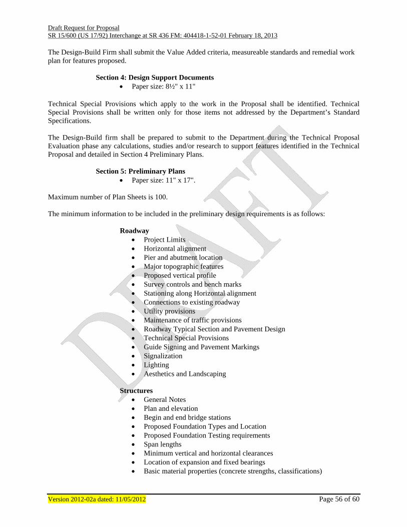
Draft Request for Proposal SR 15/600 (US 17/92) Interchange at SR 436 FM: 404418-1-52-01 February 18, 2013
Version 2012-02a dated: 11/05/2012 Page 56 of 60
The Design-Build Firm shall submit the Value Added criteria, measureable standards and remedial work plan for features proposed.
Section 4: Design Support Documents
Paper size: 8½" x 11" Technical Special Provisions which apply to the work in the Proposal shall be identified. Technical Special Provisions shall be written only for those items not addressed by the Department’s Standard Specifications. The Design-Build firm shall be prepared to submit to the Department during the Technical Proposal Evaluation phase any calculations, studies and/or research to support features identified in the Technical Proposal and detailed in Section 4 Preliminary Plans.
Section 5: Preliminary Plans Paper size: 11" x 17".
Maximum number of Plan Sheets is 100.
The minimum information to be included in the preliminary design requirements is as follows:
Roadway Project Limits Horizontal alignment Pier and abutment location Major topographic features Proposed vertical profile Survey controls and bench marks Stationing along Horizontal alignment Connections to existing roadway Utility provisions Maintenance of traffic provisions Roadway Typical Section and Pavement Design Technical Special Provisions Guide Signing and Pavement Markings Signalization Lighting Aesthetics and Landscaping
Structures
General Notes Plan and elevation Begin and end bridge stations Proposed Foundation Types and Location Proposed Foundation Testing requirements Span lengths Minimum vertical and horizontal clearances Location of expansion and fixed bearings Basic material properties (concrete strengths, classifications)
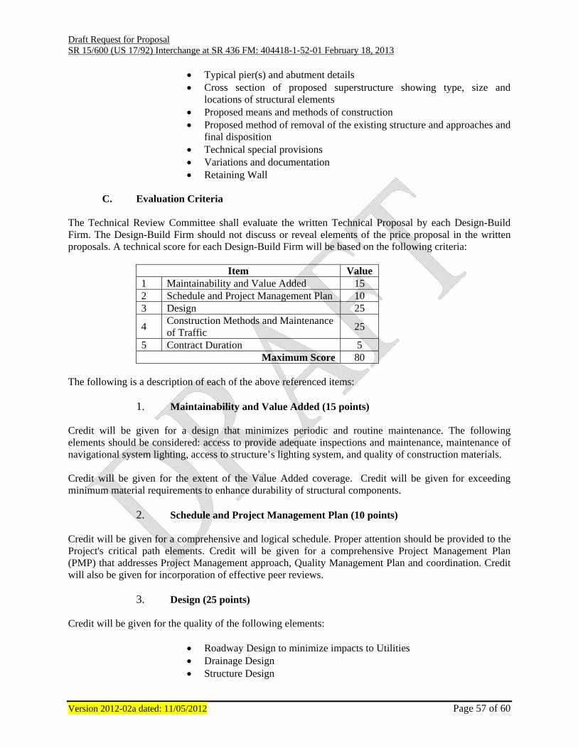
Draft Request for Proposal SR 15/600 (US 17/92) Interchange at SR 436 FM: 404418-1-52-01 February 18, 2013
Version 2012-02a dated: 11/05/2012 Page 57 of 60
Typical pier(s) and abutment details Cross section of proposed superstructure showing type, size and
locations of structural elements Proposed means and methods of construction Proposed method of removal of the existing structure and approaches and
final disposition Technical special provisions Variations and documentation Retaining Wall
C. Evaluation Criteria
The Technical Review Committee shall evaluate the written Technical Proposal by each Design-Build Firm. The Design-Build Firm should not discuss or reveal elements of the price proposal in the written proposals. A technical score for each Design-Build Firm will be based on the following criteria:
Item Value 1 Maintainability and Value Added 15 2 Schedule and Project Management Plan 10 3 Design 25
4 Construction Methods and Maintenance of Traffic
25
5 Contract Duration 5 Maximum Score 80
The following is a description of each of the above referenced items:
1. Maintainability and Value Added (15 points) Credit will be given for a design that minimizes periodic and routine maintenance. The following elements should be considered: access to provide adequate inspections and maintenance, maintenance of navigational system lighting, access to structure’s lighting system, and quality of construction materials. Credit will be given for the extent of the Value Added coverage. Credit will be given for exceeding minimum material requirements to enhance durability of structural components.
2. Schedule and Project Management Plan (10 points) Credit will be given for a comprehensive and logical schedule. Proper attention should be provided to the Project's critical path elements. Credit will be given for a comprehensive Project Management Plan (PMP) that addresses Project Management approach, Quality Management Plan and coordination. Credit will also be given for incorporation of effective peer reviews.
3. Design (25 points)
Credit will be given for the quality of the following elements:
Roadway Design to minimize impacts to Utilities Drainage Design Structure Design

Draft Request for Proposal SR 15/600 (US 17/92) Interchange at SR 436 FM: 404418-1-52-01 February 18, 2013
Version 2012-02a dated: 11/05/2012 Page 58 of 60
Signalization, Signing & Pavement Marking Utilization of existing right-of-way Innovative aspects relative to the design of the project
4. Construction Methods and Maintenance of Traffic (25 Points)
Credit will be given for construction methods that minimize impacts to the traveling public, business owners, property owners, utility owners and the environment; reduces costs; improves worker safety; and minimizes contract duration. Credit will also be given for innovative aspects related to construction. Credit will be given for a MOT scheme that minimizes disruption of roadway traffic. This shall include, but not limited to, minimization of lane and driveway closures, lane widths, visual obstructions, and drastic reductions in speed limits.
5. Construction Duration (5 Points) For the Contract Duration Item, credit will be given, at the time of bid opening, according to the following table. The number of days shown on the bid proposal form shall be the official proposed contract days.
Contract Duration Proposed (days)
Points Awarded
900 - 875 0
874 - 849 1
848 - 823 2
822 - 797 3
796 - 772 4
771 or less 5
D. Final Selection Formula The Selection Committee shall publicly open the sealed bid proposals and calculate an adjusted score using the following formula:
TS
BPP = Adjusted Score
BPP = Bid Price Proposal TS = Technical Score (Combined Scores from ELOI and Technical Proposal)
The Design-Build Firm selected will be the Design-Build Firm whose adjusted score is lowest. The Department reserves the right to consider any proposal as non-responsive if any part of the Technical Proposal does not meet established codes and criteria. Also, if PCT is greater than Maximum Allowable Contract Time (MCT) (900 calendar days) the proposal will be considered non-responsive.
E. Final Selection Process
Draft Request for Proposal SR 15/600 (US 17/92) Interchange at SR 436 FM: 404418-1-52-01 February 18, 2013
Version 2012-02a dated: 11/05/2012 Page 59 of 60
After the sealed bids are received, the Department will have a public meeting for the announcement of the Technical Scores and opening of sealed bids. This meeting will be recorded. At this meeting, the Department will announce the score for each member of the Technical Review Committee for each Proposer and each Proposer’s average Technical Score. Following announcement of the technical scores, the sealed bid proposals will be opened and the adjusted scores calculated. The Selection Committee should meet a minimum of two (2) calendar days (excluding weekends and Department observed holidays) after the public opening of the Technical Scores and Price Proposals. The Department’s Selection Committee will review the evaluation of the Technical Review Committee and the Price Proposal of each Proposer as to the apparent lowest adjusted score and make a final determination of the lowest adjusted score. The Selection Committee has the right to correct any errors in the evaluation and selection process that may have been made. The Department is not obligated to award the contract and the Selection Committee may decide to reject all proposals. If the Selection Committee decides not to reject all proposals, the contract will be awarded to the Proposer determined by the Selection Committee to have the lowest adjusted score.
F. Stipend Awards
The Department has elected to pay a stipend to a limited number of non-selected Short-Listed Design-Build Firms to offset some of the costs of preparing the Proposals. The non-selected Short-Listed Design-Build Firms meeting the stipend eligibility requirements of the Project Advertisement and complying with the requirements contained in this section will ultimately be compensated. The stipend will only be payable under the terms and conditions of the Design-Build Stipend Agreement and Project Advertisement, copies of which are included with this Request for Proposal. This Request for Proposal does not commit the Department or any other public agency to pay any costs incurred by an individual firm, partnership, or corporation in the submission of Proposals except as set forth in the Design-Build Stipend Agreement. The amount of the stipend will be $40,000.00 per non-selected Short-Listed Design-Build Firm that meets the stipend eligibility requirements contained in the Project Advertisement. The stipend is not intended to compensate any non-selected Short-Listed Design-Build Firm for the total cost of preparing the Technical and Price Proposals. The Department reserves the right, upon payment of stipend, to use any of the concepts or ideas within the Technical Proposals, as the Department deems appropriate.
In order for a Short-Listed Design-Build Firm to remain eligible for a stipend, the Short-Listed Design-Build Firm must execute with original signatures and have delivered to the Department no later than one (1) week after the Short-List has been posted, four (4) originals of the Design-Build Stipend Agreement, Form No. 700-011-14. The Short-Listed Design-Build Firm shall reproduce the necessary copies. Terms of said agreement are non-negotiable. A fully executed copy of the Design-Build Stipend Agreement will be returned to the Short-Listed Design-Build Firm.
A non-selected Short-Listed Design-Build Firm eligible for stipend compensation must submit an invoice for a lump sum payment of services after the selection/award process is complete. The invoice should include a statement similar to the following: "All work necessary to prepare Technical Proposal and Price Proposals in response to the Department's RFP for the subject Project". VIII. Bid Proposal Requirements.
A. Bid Price Proposal Bid Price Proposals shall be submitted on the Bid Blank form attached hereto and shall include one lump

Draft Request for Proposal SR 15/600 (US 17/92) Interchange at SR 436 FM: 404418-1-52-01 February 18, 2013
Version 2012-02a dated: 11/05/2012 Page 60 of 60
sum price for the Project and the number of calendar days within which the Proposer will complete the Project. The lump sum price on the Bid Proposal shall be separated into three sequences (404418-1-52-02 for Aesthetics/Irrigation, 404418-1-52-03 for Mast Arm upgrades, and 404418-1-52-01 for the remainder of the project) as outlined in the Bid Blank form. The Bid Price Proposal shall include all costs for all design, geotechnical surveys, architectural services, engineering services, Design-Build Firms quality plan, construction of that portion of the Project, and all other work necessary to fully and timely complete that portion of the Project in accordance with the Contract Documents, as well as all job site and home office overhead, and profit, it being understood that payment of that amount for that portion of the Project will be full, complete, and final compensation for the work required to complete that portion of the Project. One (1) hard copy and two (2) digital copies of the Price Proposal shall be hand delivered in a separate sealed package to the following:
Ms. Michelle Sloan, Professional Services, MS 4-524 Florida Department of Transportation 719 South Woodland Boulevard Deland, Florida 32720
The package shall indicate clearly that it is the Price Proposal and shall identify clearly the Proposer’s name, and Project description. The Bid Price Proposal shall be secured and unopened until the date specified for opening of Price Proposals.