design applications of sandwich composite shells with
TRANSCRIPT

1 MHP Systems Engineering, <[email protected]> 2 Graduate Student, University of New Orleans, <[email protected]> 3 PhD. Formerly at The University of Texas at Austin, <[email protected]>
Proceedings of the
Annual Stability Conference
Structural Stability Research Council
San Antonio, Texas, March 21-24, 2017
Design applications of sandwich composite shells with enhanced bond
Peter W. Marshall1, Vul Thang
2, Jinbo Chen
3
Abstract
Design, analysis, and construction details of steel-polymer-steel (SPS) and steel-concrete-steel
(SCS) sandwich composite caissons for offshore wind farms are described. Simplified analyses
are used as a prelude to finite element and other more detailed methods.
1. Introduction
Wind energy is getting more important today, as oil and natural gas are being replaced to reduce
global warming caused by carbon dioxide emissions. The environmental pollution can be
reduced by increasing renewable wind energy. Compared to onshore wind turbines, offshore
wind turbines have the advantages that the energy potential is greater in offshore fields, large
power turbines can be installed, and there are no aesthetic issues. It is expected that the
renewable energy industry will increase significantly by going offshore (the current onshore
renewable energy is slightly over 10% of the electricity generation in the US).
In European countries, offshore wind farms have already been developed, and billions of dollars
have been spent generating clean energy for the past many years. There are about 2500 wind
turbines spinning in offshore Europe today. In 2015, over 3,000 megawatt (MW) of offshore
wind power was produced in Europe, nearly 100 times U.S. offshore capacity.
Several offshore wind farm projects have been started off the United States’ east coast. For
example, Block Island Wind Farm completed installation of five 6MW turbines for a 30MW
wind farm in 2016. Power is projected to cost 24 cents/kW-hr. Deepwater Wind is also studying
other, larger offshore wind farm projects.
Fig. 1 shows potential offshore wind farm project locations. There is high hope that offshore
wind industry will boom in the near future. Good deep water prospects (30-80m water depth) lie
in the Great Lakes, and off North Carolina, New England, Corpus Christi TX, north of Point
Conception CA, and south of Buras LA. Large diameter mudslide resistant caissons are
particularly suitable for soft soil site off the Mississippi Delta near Buras.

2
Figure 1: United States offshore wind resource by region and depth (Credit: NREL)
Fig. 2 below shows wind turbine structures previously studied in various depths. Composite
sandwich shell caisson types are desirable because they are durable, suitable for harsh
environment, able to accommodate heavy topsides, suitable for diverse sea floor conditions, and
for 30-60m (100-200ft) deep water, beyond the reach of all-steel caissons.
Figure 2: Types of wind turbine foundations (extracted from BOEM website)
2. Vertical Caisson
The sandwich pipe system (Marshall 2003) has previously been studied for a wind turbine
foundation caisson in 50m (165ft) water depth. Compared to a steel-only design with 67mm
solid wall, the 19-30-19mm steel-polymer-steel composite would save 43% on steel weight. Its
favorable local buckling characteristics enabled a 12m (40ft) diameter at the mudline, for an
acceptable natural period in a soft-soil site conducive to deep pile-driving.

3
2.1Background
104m diameter wind turbines, capable of generating 3.6 megawatts of electric power became
available in 2003. Existing smaller installations were onshore or in shallow water. There are a
number of promising offshore sites in deeper water, ranging from 30m to 80m in water depth.
Soil conditions range from soft clay, to hard clay, to dense sand, to rock, in the order of
increasing difficulty.
An estimate of the present value of the power sales income stream from each turbine suggested
that installation cost more than about $9 million per MW (in 2016 US dollars) would not be
economically attractive. Allowing for the costs of the 3.6 MW turbine generator, rotor, and
topside tower, supplied by the manufacturer, offshore supporting substructures with installed
cost exceeding about $12-million (in 2016 US dollars) can probably be ruled out. Fixed
structures with natural periods longer than 3.6 seconds are unacceptable for turbine dynamics,
and the water depth range is not optimal for the use of compliant structures. Finding structural
solutions within these constraints will be challenging.
Existing installations in water depths less than 20m are supported by steel caissons (monopiles)
up to 5m in diameter and 50mm wall thickness (D/t of 100). These monopiles are driven into the
sea floor, often with the aid of internal excavation (jetting or drilling) for difficult soils, and are
at the limit of conventional wisdom for driven piling. A parametric study on extending
conventional caissons to deeper water reveals that feasible solutions can be found in water depths
up to 40m (130ft), by moderately increasing pile diameter. Keeping a constant D/t of 100 means
that pile weight increases as the square of the diameter. Caissons in deeper water have also been
analyzed; however, the 3.6-second constraint was not satisfied. Also, in difficult soils, the
required penetration for overturning stability exceeds the limits for drivability with the largest
available pile hammers. Preliminary design of a composite monopile caisson was performed for
a 50m site in soft clay – one cycle of the design spiral.
2.2 Introduction to the sandwich pipe system
Concentric tubulars, with portland cement grout in the various annuli, have been used as oilwell
casings since the late 1800’s, with the objective of sealing off formation fluids. In constructing
offshore platforms from the 1950’s onward, piling driven through the legs of template-type space
frames, skirt piles driven through sleeves which do not extend to the water surface, and insert
piles installed through previously driven piling, all have the annulus around each pile grouted to
establish a structural connection by means of shear transfer in the grout.
These long grouted connections remain durable in the face of progressive disbonding and
deterioration of the grout near their ends. Progressive failure is a more serious problem in short
grouted connections as used in North Sea caisson foundations for many existing offshore wind
turbines.
It has also long been recognized that grouting the pile-to-leg annulus has the advantages of
creating a single composite member, reducing the tendency for elastic local buckling of the
typically thin jacket leg, and strengthening brace-to-leg tubular connections, or nodes.

4
Intelligent Engineering has developed the steel-polymer-steel Sandwich Plate System (SPS)
starting in the 1990s, in close collaboration with BASF AG. BASF Elastogran manufactures the
two-component polymer whose solidified state exhibits the following properties: bond strength
of approximately 14MPa (2000psi) against grit blasted metal; elastic strain range of
approximately 6%, with ductile behavior beyond the elastic range; an elastic modulus that can be
varied from 1/800 to 1/100 that of the load-carrying steel layers; and a density similar to that of
seawater.
Sandwich composites can replace conventional stiffened metal plates in maritime, offshore and
civil engineering structures. They provide benefits in fabrication, performance, cost and safety
for both civilian and military applications. Prefabricated panels may be used for new
construction. For repair and conversion purposes, the SPS Overlay is being applied to the traffic
decks of ferries. This bonds a new top plate to the existing structure, in a process that is simple,
safe, non-disruptive and very fast - restoring corroded and sagging structures to class without
having to remove the old deck and the myriad utility systems and structure attached to its
underside.
For tubular applications of the SPS concept (Marshall 2003), improving the resistance of
cylindrical members to local buckling, denting, and ovalizing is achieved by increasing the ratio
of local wall bending stiffness or strength to membrane stiffness or strength. This allows the
diameter to be increased without a corresponding increase in metal thickness. The novelty here
is stating this as generic design concept, opening the way to many different methods of achieving
it. Simply making a tubular member thicker improves these resistances by increasing the
aforementioned ratio. This improvement is well known, but the importance of the ratio per se
was not previously recognized.
Patent rights were acquired by IE-SPS for commercial development - engineering, supplying the
elastomer, and controlling the injection process. The steel-polymer-steel sandwich pipe system
was initially studied for application to suction anchors that are used to moor deepwater spars and
semi-submersibles for offshore oil production. These caissons are up to 25-ft (7.5m) diameter
with penetration of two to six meters. They are installed to within a degree or two of vertical,
without guides, using self-weight and suction (supplied by the 50psi pump on an ROV) to
achieve penetration. Two single-wall caissons experienced local collapse during installation
from too much suction pressure at Devil’s Tower, when harder-than-expected soils were
encountered. Double-wall composite was shown to provide a substantial increase in hydrostatic
collapse resistance, either as a retrofit solution or for new design. However, the concept got a
cool reception from organizations understandably unwilling to insert proof-of-concept R&D
efforts into a tightly scheduled project already underway.
2.3 Composite monopile caisson
A preliminary design has been completed for the Mississippi Delta site (50m water, soft clay).
This design is predicated on data furnished by MHP’s clients, MMI Engineering and the turbine
manufacturer (GE).
The composite monopile caisson appeared to be feasible, both technically and economically. Its
total installed cost is estimated at $9.8 million per caisson, excluding the generator, rotor, and

5
tower supplied by the turbine manufacturer. Steel fabrication costs include a premium for
concentric pipes over plain pipe, based on fabrication experience with vertical riser support
buoys including machined transition rings. Costs for the elastomer core and its injection are
about 9% of the total, subject to confirmation. Installation cost assumes the wind farm project
hires a robust installation vessel, doing ten caissons in one mobilization. Some weather
downtime and contingencies are included.
Overview of the caisson and tower is shown in Fig 3. It is quite a scale-up from previously
installed tapered wellhead caissons for in the Gulf of Mexico.
Figure 3: Very large diameter caisson for wind turbine foundation (a) view (b) bending moment.
The 1342-tonne caisson (without tapered transition and mast) would be lift-installed by a large
derrick barge, with the top of the caisson at +71m (237ft) at touch-down. Self-weight
penetration in soft clay should be enough to assure temporary stability without guides; then the

6
largest class of offshore pile-driving hammer would drive it to grade. Because wave surge is not
amplified as much as in shallow water, this installation work can be carried out from floating
equipment rather than a jack-up platform.
A separate conical transition piece runs from elev. +3m to the manufacturer’s tower flange at
elev. +15m. The base of the transition would be field-cut and welded to make a final adjustment
for verticality. An upward looking stabbing cone would be incorporated for the tower lift, so the
derrick can set the tower and forget it – i.e. start rigging up for the next lift while the bolted
connection is being made.
An estimated bending moment curve is also shown in Fig. 3. Bending moment at the base of the
tower was furnished by the turbine manufacturer. Bending moment at the mudline is based on
the MMI’s all-steel 7.5m design. Bending moment pattern below the mudline is for a caisson on
the verge of post-hole instability when applied overturning moment is increased by the factor of
safety.
Figure 4: Details of Caisson
Details of caisson architecture are shown in Fig. 4. These include the steel-polymer-steel
sandwich with integral solid rings to keep it round during fabrication, and to provide for
reasonable batch size for polymer injection. Diameter tapers from 7.5m (25ft) at the top, to 12m
(40ft) at and below the mudline. Plate thicknesses are mostly in the 12 to 19mm (1/2 to 3/4 inch)
range, with thicker plates at the driving head and shoe (D/t of about 120). All welded
attachments (spiders, appurtenances, lifting devices, etc) would be to the rings, and not to the

7
composite. The plate-to-ring lap welds limit fatigue performance to AWS D1.1 category D,
which is one step lower than the butt welds in plain API Spec 2B pipe.
The soft clay soil is slightly underconsolidated, with a shear strength gradient of 6 psf/ft. The
12m diameter caisson has sufficient post-hole resistance at achievable penetration. In contrast to
the hard soil sites, driving to the indicated depth is feasible, with the largest offshore hammer
operating at 77% power. However, water must be pumped out during driving to keep the
internal water level at or slightly below sea level; otherwise a head build-up on the inside of the
taper will retard penetration.
Large diameter issues have been explored relative to constructability of the composite;
hydrostatic collapse, and local buckling. These are described in detail in the next section of this
paper. 12m diameter appears to be quite feasible and efficient, when the SPS composite is used.
Because the composite construction increases the shell bending stiffness without changing the
membrane thickness, the effective thickness for determining elastic local buckling stress 4.5
times the thickness of the individual steel layers. The highest effective D/t is 152, for which the
local buckling stress is 84% of yield, using API criteria.
Theory of the effective thickness approach was presented (Marshall 2003). Teff = √(12 I / A)
where I and A respectively are the transformed section moment of inertia and area per unit of
circumference.
Strength design is dominated by beam bending stress on the combined tubular steel wall
thickness, with the contribution of the elastomer core being ignored. Working stress design
includes reduction for local buckling and the API 0.85 utilization limit for monopile
structures. 50 ksi steel is effectively utilized in places, with mild steel where constructability
defined the minimum thickness.
Dynamics are estimated using textbook formulas modified by a calibration factor. 60m water
with hard soil approximates the cantilever bending length of 50m water with soft soil. Mass is
dominated by contained and virtual water, rather than structural mass. The 12m diameter
composite has 1.8 times the mudline moment of inertia of the smaller but heavier solid steel
design, and a preliminary natural period of 3.0 sec. Previous generic random wave analyses
suggest this period leads to a 1.15 dynamic amplification of wave forces, and 25-years fatigue
life.
2.4 Large diameter issues
The proposed design is of unprecedented diameter. Regarding practical limits to monopile
diameter, the following issues may be noted.
Very large caissons may be limited to soft soils, where they can be installed by suction or
driving. Installation in more difficult soils requires cleaning out the interior of the pile; however,
drilling becomes more like tunneling over 5m diameter and mining over 12 meters. For tapered
caissons, the tunneling mole would have to be collapsible, in order to pass through the smaller
upper diameter.
8
Driving has been done up to at least 5m diameter, with D/t of 100. The proposed design is
tapered to 7.5m with D/t of 125 in the solid driving head, and an effective D/t of 128 in the SPS
composite below the corrosion allowance. We would be violating the API D/t limits for heavy
driving, and may have to use the "soft" setting on HBG-style hydraulic hammers.
For strength design, the API RP2A local buckling penalty is not too severe for unstiffened tubes
with D/t up to 300. However, these criteria were derived from tests representing the residual
stresses and geometric imperfections of single-wall welded tubes. Applying these same criteria
to the effective D/t of SPS composites is speculative, and should be confirmed by inelastic finite
shell element analysis and scaled-down prototype squash tests.
Soil induced collapse in inconvenient hard layers may require a heavier driving shoe than the D/t
of 120 currently provided, where cemented sand layers or rock are encountered. At Goodwyn
“A” off NW Australia, large diameter piles got dinged at the tip during stabbing; driving then
grew that imperfection to complete flattening of the cross-section, as the piles were extruded into
rock-like calcareous sand. The post-mortem investigations developed a stability theory to
predict this phenomenon.
Estimated hydrostatic collapse resistance for the present design limits the safe internal drawdown
to 10m. Again, this result could use verification using elastic finite elements to model the
composite sandwich and the beneficial effect of the solid rings. If we wanted more drawdown
(up to 25m) for suction-assisted driving, collapse resistance could be enhanced by simply
increasing the thickness of the elastomer core, keeping the steel layers the same.
Handling during fabrication will be delicate, and require internal or external spiders, especially
for the thin wall steel elements during assembly and core injection. Even with integral rings at
5m spacing, elastomer injection is limited to 5m lifts (submerged) plus 0.1 bar pumping
overpressure. Elastomer injection governs the minimum inner steel layer thickness for much of
the caisson. This preliminary analysis assumed axisymmetric pressures; proper consideration of
elastomer injection with the caisson laying on its side would require a more sophisticated finite
element analysis. Premature thickening of the elastomer, and the resulting uneven increase in
pumping pressure, would be disastrous.
Maintaining roundness during transport and handling is considered. With the existing design,
support cradles 30 degrees either side of centerline are indicated. These will probably be needed
for load-out and transport anyway, as the fully assembled tapered caisson cannot simply be
rolled around on a flat surface.
2.5 Conclusion
Based on preliminary work to date, the tapered monopile caisson appears to be feasible for a site
with 50m water and soft clay soil. However, it represents a significant step-out from precedent.
3. Suction Buckets
Offshore California, a rock-like shale formation at shallow penetration would limit the
driveability of large diameter single caissons. However, a large suction caisson, penetrating only
the soft near-surface soils, provides stability against overturning, sliding, and settlement, with

9
suitable safety factors. Its steel-concrete-steel composite shell would follow the methodology
proposed for Arctic offshore structures (Marshall 2009 and 2012, Palmer 2015}.
Figure 5: View of turbine tower with suction caisson
The suction caisson is a 7-cell circular cluster, with the cells just touching. The center cell
encloses the 12m diameter vertical structure. Its ID is 12.3m, and it has a single 38mm steel
wall, leaving a 0.15m (6 inch) annulus for a grouted field connection. Suggested wall design for
the six 12.3m OD suction cells is 19-150-19mm steel-concrete-steel. Their domes will have
same wall design and 12m radius.
Applied environmental loads at the mudline are 1275 tonnes lateral load and 53,000 tonne-
meters overturning moment. Total vertical load is 6637 tonnes, including caisson weight.
Design calculations considered the suction caisson as a six cell cluster surrounding the 12m
diameter mast. The 6-cell suction caisson would be installed first, using manifold ROVs to
pump seawater out of the cells, creating a suction downforce to augment the caisson weight for

10
penetration of the sea floor. Controlled pumping from each of the cells would keep the caisson
level. Penetration resistance consists of friction on the inner and outer sidewall, and bearing
failure at the cutting edges. Maximum suction pressure was estimated at 0.55 bar (8psi) at 12m
(40ft) penetration into the Carpenteria - Point Conception seafloor soil profile (Marshall 2016)
Suction pressure is limited by inflow failure of sand at the cutting edge (see Fig. 6). Instead of
suction at the base of the soil plug, we get heave pressure.
Figure 6: Sand inflow creates heave pressure at the base and limits uplift capacity at mudline
Depending on variable site stratigraphy, the caissons may bottom in either clay or sand. Soil
mechanics consideration of vertical loads on each caisson cell are given in Table I. Suction
caissons in clay are well known. For sand, see (Houlsby et al 2005). Our treatment of a layered
clay/ sand systems is original. Clean sand at the tip would create heave pressure at the base of
the clay plug, instead of suction. Compared to classical values of Nq, our value of 10 understates
bearing capacity and overstates heave pressure – both conservative.

11
Table I: Soil Mechanics Considerations
CASES CLAY CLAY/ SAND SAND
1 outside friction (pDoczdz) clay + sand intervals (pD(kotan'zdz
2 inside friction i not o <--- see ---> ki not ko
3 tip resistance (pDt)(P'o + 6c) (pDt)P'oNq (pDt)P'oNq
4 end bearing shallow 6cA A Nq P'o A Nq P'o at deep penetration
deep (P'o + 9c) A Nq 10 for = 32⁰ Nq 23 for = 32⁰
5 end suction for uplift shallow neglect - A P'o/Nq neglect for static case
deep (6c-P'o) A (heave pressure)
pore water undrained hydrostatic (drained) in flow depends on movement or
sand if no shallow gas pumping rate
INSTALLATION CAPACITY wt. + suct. = 1+2+3 wt. + suct. = 1+2+3 suction depends on flow rate;
liquifaction possible
bearing 1 + 4 - wt. - plug 1 + 4 - wt. - plug 1 + 4 - wt. - plug
uplift 1 + 5 + wt. + plug 1 + 5 + wt. + plug 1 + 2 + wt.
DESIGN CASE 3611 t * 5861 t* used 2200 t
estimate. Foundation 2385 t 1733 t used 1760 t
(40' dia., 40' deep, each cell) * less if adjacent cell is loaded to uplift limit
Typ. DEPTH LIMIT for installation H = 2D to 6D wt. + suct. = 1+2+3 H = D/2 + self penetration
n/a this design
In-place, frontal P-Y resistance in the clay, silt and sand layers was estimated at 3514 tonnes
using methods of API RP 2GEO, and basal sliding resistance was 4500 tonnes, 38% and 62% of
the total, respectively.
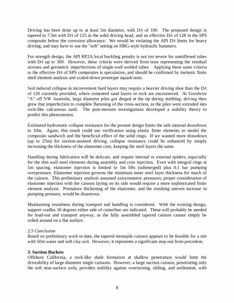
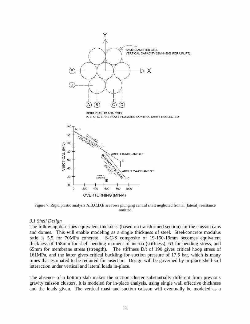
Overturning resistance was estimated at 95,000 tonne-meters, using the vertical load capacity of
individual caisson cells. Overturning-vertical interaction from limit state analysis (Marshall
1976, Bransby 1999, Chen 2016) is shown in Fig. 7. The final safety factors for were 5.5 on
lateral load, 1.64 on overturning, and 3.5 on vertical settlement. Ellipsoidal interaction gives a
combined safety factor of 1.5 for the extreme storm condition.
12
Figure 7: Rigid plastic analysis A,B,C,D,E are rows plunging central shaft neglected frontal (lateral) resistance
omitted
3.1 Shell Design
The following describes equivalent thickness (based on transformed section) for the caisson cans
and domes. This will enable modeling as a single thickness of steel. Steel/concrete modulus
ratio is 5.5 for 70MPa concrete. S-C-S composite of 19-150-19mm becomes equivalent
thickness of 158mm for shell bending moment of inertia (stiffness), 63 for bending stress, and
65mm for membrane stress (strength). The stiffness D/t of 190 gives critical hoop stress of
161MPa, and the latter gives critical buckling for suction pressure of 17.5 bar, which is many
times that estimated to be required for insertion. Design will be governed by in-place shell-soil
interaction under vertical and lateral loads in-place.
The absence of a bottom slab makes the suction cluster substantially different from previous
gravity caisson clusters. It is modeled for in-place analysis, using single wall effective thickness
and the loads given. The vertical mast and suction caisson will eventually be modeled as a

13
unit. Method of tying everything together involves fillet welds in holes or narrow-grove welds at
primary support points where cells touch, pipe struts spanning accessible gaps of 0.3m (1ft)
nearby, and Flowdrill ties (Banks 1993) to transmit tension loads through the sandwich.
Rigid support would be inappropriate representation of soil-structure interaction. Coefficients of
subgrade reaction (spring supports) might be suggested. However, modeling the surrounding
soil in 3-D nonlinear elements would be superior.
For the present, however, soil reactions were calculated by hand, using patterns derived from
judgement and experience, and the resultant actions were back-computed by considerations of
static equilibrium. These loads are shown in Fig. 8 below, along with a summary of ABAQUS
results for a simplified structural model in Fig. 9.
Figure 8: Loads for ABAQUS

14
Figure 9: ABAQUS Results for Single Suction Cell, looking into open bottom
For vertical loading, the six caisson cells are cantilevered out from the central shaft. Stresses in
the transformed section are close to allowable. For lateral loading, transforming soil pressures
into beam shear gradually causes only minimal shell bending, and the membrane shear is also
low. Suction anchors typically have very high D/t ratio.
Results from a more comprehensive analysis (Fig. 10) may be included in a future presentation.
Figure 10: Six Cell Caisson Cluster around Turbine Tower Base

15
4. Bond Enhancement
Disbonding of solid core material from the steel shell is a generic problem for sandwich
composites, limiting their application in heavy construction. Research at National University of
Singapore (Marshall 2009, 2012) and Lamar University (Thang 2016) has studied internal
reinforcement schemes and surface bond enhancement methods, to address this problem.
Tentative procedures for robust design have emerged, and are described, along with suggestions
for further research.
Double-wall steel-concrete-steel (SCS) composite has been proposed for the “Singapore Cone”
Arctic offshore structure. The SCS vault performs well under uniform pressure, but can fail
prematurely under partial asymmetric loading. These shells will often experience a punching
shear failure or flexural steel plate buckling, which is exacerbated by the loss of bond between
the steel wall and concrete interface. In the Lamar research, a construction friendly method
using an array of welded mini studs to improve the steel-concrete interfacial bond, was studied.
Two workable Type I Portland cement grout mixes were tested as the bulk material: plain, and
fiber reinforced. Studded concrete-steel interfaces were tested under mode I interface peeling
(Fig. 11), and mixed mode II shear. The small scale tests were also modeled with the nonlinear
finite element analysis software ABAQUS, and the numerical results were compared against the
laboratory experimental results.
(a)
(b)
Figure 11: Peeling numerical model with embedded studs a) before loading and
b) Deformed shape after loading (section at studs near mid-width). Distorted mesh indicates zone of cracking.

16
After qualitatively matching the computational results with experimental results, a large scale
prototype SCS was modeled and designed, with working stresses limited to the elastic range.
Mode I peeling ultimate strength of 0.46 was used for the prototype analysis, with mixed
mode II shearing limited by bulk concrete away from the studded bond surface.
The objective of ongoing research is to develop methodology and designs for driven and suction
caissons of large diameter, using composite steel-concrete-steel (SCS) construction.
Prior Arctic caisson design analysis has been in the elastic range, limiting bond peeling tension
and shear stresses to safe values. The proposed new methodology for research at the University
of New Orleans is to use calibrated phenomenological cohesive layers for Mode I peeling and
Mode II shear at the bond interface zone, along with Abacus damage plasticity for the bulk
concrete in between the steel layers of a Steel-Concrete-Steel (SCS) composite shell. The
Cambridge nonlinear model would be used to model the 3-D soils in which the caisson is
embedded. A coarse mesh would be used to model large complex structures.
Detailed analysis and design calculation of a multi-cell suction bucket foundation for an offshore
wind farm, including obtaining design data, would follow the research, if suitable interest is
found. The proposed effort would include 6000 hours of study, research, and development - three
years full time or six years part time. Initial investigation started as a fracture mechanics
classroom project in Fall 2016, at the University of New Orleans.
5. Conclusion
Preliminary research and design has revealed interesting modes of instability, ranging from soil
flow, to shell buckling, to fracture-like peeling at the bond surface. The proposed research will
provide a new methodology for non-linear analysis and design of composite sandwich caissons
for offshore wind farm and Arctic applications.
References
Banks, G. (1993). “Flow drilling for Tubular Structures.” Tubular Structures V, Nottingham.
Bransby, M.F., Martin, C.M. (1999). “Elasto-plastic modeling of bucket foundations.”
Numerical Models in Geomechanics, NUMOG VII.
Chen, J. et al. (2016). “Two-dimensional lower bound analysis of offshore pile foundation
systems.” International Journal for Numerical and Analytical Methods in Geomechanics.
Volume 40, Issue 9, Pages 1321-1338
Houlsby, G.T. et al. (2005). “The tensile capacity of suction caissons in sand under rapid
loading.” Frontiers in Offshore Geotechnics, ISFOG
Houlsby, G.T. et al. (2005). “Design procedures for installation of suction caissons in sand.” ICE
Geotechnical Engineering 158, Pages 135-144
Marshall, P.W. et al. (1976). “Failure Modes for Offshore Structures.” Proceedings Boss, Vol II
Marshall, P.W. (2003). “Enhanced strain-based design of tubular piling and pipelines.”
Proceedings SSRC, Baltimore
Marshall, P.W. (2009). “The effect of bond enhancement on curved sandwich shells under
contact loading.” Proceedings SSRC, Phoenix
Marshall, P.W. et al. (2012). “Development of SCS sandwich composite shell for Arctic
caissons.” Proceedings Arctic Tech Conference, Houston, OTC 23818

17
Marshall, P.W. (2016). National University of Singapore Tripod and TLP for Point Conception
wind farm (2006). Proceedings MTS-IEEE Oceans’16, Monterey, CA.
Palmer, A.C. et al. (2015). “Arctic platform construction using steel-concrete-steel sandwich
composite.” Proceedings 23rd
Port & Ocean-engineering under Arctic Conditions, POAC,
Trondheim
Thang, V. et al. (2016). “Studded bond enhancement for S-C-S sandwich shells.” Ocean
Engineering Journal, Elsevier, Volume 124, Pages 32-41