design and vibration analysis of steam turbine low ...ijesr.org/admin/upload_journal/journal_g...
TRANSCRIPT

ISSN 2277-2685 IJESR/May 2018/ Vol-8/Issue-5/1-7 G Prasanna Kumar et. al., / International Journal of Engineering & Science Research
*Corresponding Author www.ijesr.org 1
DESIGN AND VIBRATION ANALYSIS OF STEAM TURBINE LOW PRESSURE BLADE-3 TO ENHANCE EFFICIENCY
G. Prasanna Kumar*1, BVS Rao2, V Suwrana Kumar1 1Assistant Professor, Dept. of Mech. Engg., MJCET, Hyderabad, India.
2Assistant Professor, Dept. of Mech Engg. CBIT, Hyderabad, India.
ABSTRACT
The development of country depends on the amount of power production. Thermal power plant plays a major role in power production. In thermal power plant steam turbine is one of the essential components and it produces rotational work which is important for production. Limited primary energy resources and awareness of environmental pollution has led to ever increasing endeavor to develop new steam turbine power plants with the highest possible efficiencies. Even small step increase in efficiency can result in major saving for the customer. As overall cycle efficiency is strongly dependent on steam turbine performance the efforts are directed primarily towards improvement in reducing the losses. The principle of steam turbine is steam energy is converted mechanical work by expansion through the turbine. The expansion takes place through a series of fixed blades (nozzles) and moving blades each row of fixed blades and moving blades is called a stage. The moving blades rotate on the central turbine rotor and the fixed blades are concentrically arranged within the circular turbine casing which is substantially designed to withstand the steam pressure. The main objective of the paper to identifying the losses occurring in the turbine and to carry vibration analysis test of turbine LP blades to improve efficiency.
Keywords: Vibration analysis, Steam Turbine, LP blades.
1. INTRODUCTION
A steam turbine is a mechanical device that extracts thermal energy from pressurized steam, and converts it into rotary motion. It has an emergency stop valve (ESV),control valve(CV), and high & low pressure turbines.
Steam turbines has almost completely replaced the reciprocating piston steam engine because of its greater thermal efficiency and higher power-to-weight ratio. Because the turbine generates rotary motion, it is particularly suited to be used to drive an electrical generator – about 80% of all electricity generation in the world is by use of steam turbines. The steam turbine is a form of heat engine that derives much of its improvement in thermodynamic efficiency through these of multiple stages in the expansion of the steam, which results in a closer approach to the ideal reversible process.
Many industrial plants like sugar, pulp, paper, chemicals, fertilizers, steel and petroleum refineries require steam at low and medium pressures for process purposes and power for driving numerous machines, like turbo generators, compressors, pumps etc ., incorporated in the plant.
The steam turbines are utilized in several industries viz.. Paper, fertilizers, chemical petro chemicals, sugars, refinery, metallurgical etc foe power generation and mechanical drives already described. The following illustration explains the selection - application criteria of industrial turbines.
2. FORMULATION AND VALIDATION · In order to gain physical insight into the flexural dynamics of such turbine blades, the blade geometry is simplified to that of uniform and straight cantilever beams. · For the analysis, a cantilever beam of length 0.45m and cross section 0.003m x 0.2m is taken. · Mathematical Analysis is commutated and compared with ANSYS solution.
G Prasanna Kumar et. al., / International Journal of Engineering & Science Research
Copyright © 2018 Published by IJESR. All rights reserved 2
2.1 Mathematical Analysis
For a cantilever beam subjected to free vibration, and the system is considered as continuous system in which the beam mass is considered as distributed along with the stiffness of the shaft, the equation of motion can be written as (Meirovitch, 1967),
(1)
Where, E is the modulus of rigidity of beam material, I is the moment of inertia of the beam cross-section, Y(x) is displacement in y direction at distance x from fixed end, ω is the circular natural frequency, m is the mass per unit length, m=ρA(x), ρ is the material density, x is the distance measured from the fixed end.
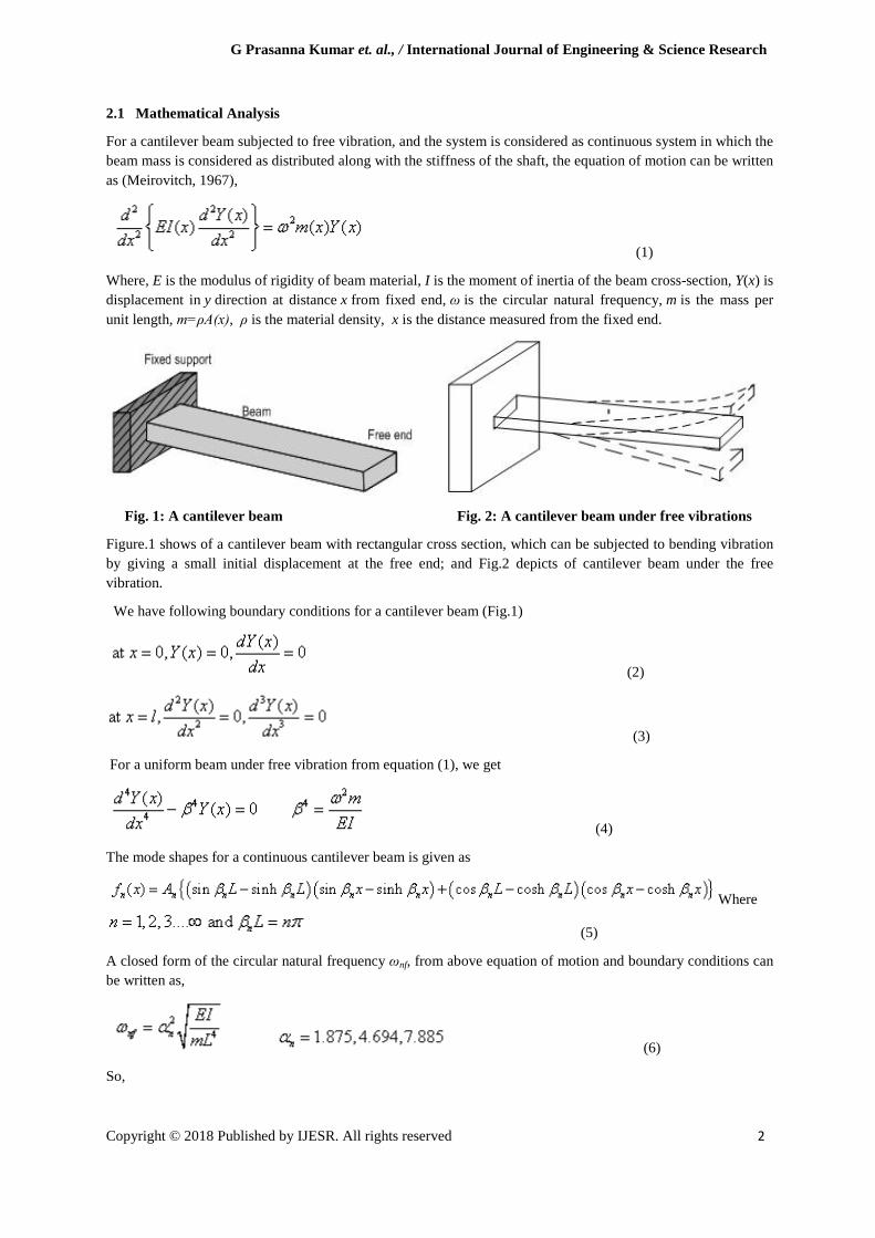
Fig. 1: A cantilever beam Fig. 2: A cantilever beam under free vibrations
Figure.1 shows of a cantilever beam with rectangular cross section, which can be subjected to bending vibration by giving a small initial displacement at the free end; and Fig.2 depicts of cantilever beam under the free vibration.
We have following boundary conditions for a cantilever beam (Fig.1)
(2)
(3)
For a uniform beam under free vibration from equation (1), we get
(4)
The mode shapes for a continuous cantilever beam is given as
Where
(5)
A closed form of the circular natural frequency ωnf, from above equation of motion and boundary conditions can be written as,
(6)
So,

G Prasanna Kumar et. al., / International Journal of Engineering & Science Research
Copyright © 2018 Published by IJESR. All rights reserved 3
First natural frequency
(7)
Second natural frequency
(8)
Third natural frequency
(9)
The natural frequency is related with the circular natural frequency as
Where I, the moment of inertia of the beam cross-section, for a circular cross-section it is given as
(11)
Where b and d are the breadth and width of the beam cross-section
Fig. 3: The first three undamped natural frequencies and mode shape of cantilever beam
The undamped natural frequency of a steel beam with l = 0.45 m, d = 0.003 m, and b = 0.02 m.

G Prasanna Kumar et. al., / International Journal of Engineering & Science Research
Copyright © 2018 Published by IJESR. All rights reserved 4
First natural frequency
Second natural frequency
Third natural frequency
2.2. ANSYS solutions
Using ANSYS, the solution for the same problem is
The first three frequencies are (in Hz)
Fig. 4: Natural frequency in first mode shape of T-3 blade

G Prasanna Kumar et. al., / International Journal of Engineering & Science Research
Copyright © 2018 Published by IJESR. All rights reserved 5
Fig. 5: Natural frequency in second mode shape of T-3 blade
Fig. 6: Natural frequency in third mode shape of T-3 blade
Table 1: Comparison of the solutions
2.3 Natural Frequency Test (NFT) at SITE
Fig. 7: Natural frequency test at site
G Prasanna Kumar et. al., / International Journal of Engineering & Science Research
Copyright © 2018 Published by IJESR. All rights reserved 6
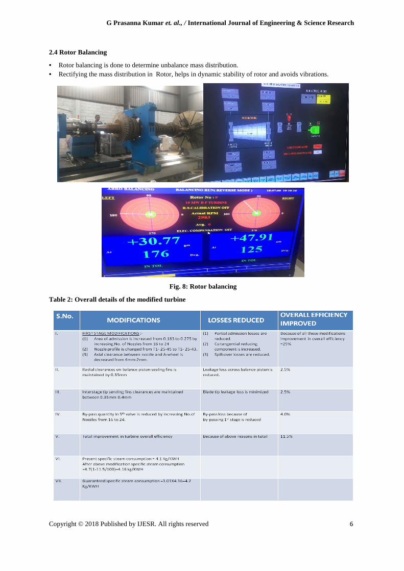
2.4 Rotor Balancing
• Rotor balancing is done to determine unbalance mass distribution. • Rectifying the mass distribution in Rotor, helps in dynamic stability of rotor and avoids vibrations.
Fig. 8: Rotor balancing
Table 2: Overall details of the modified turbine
G Prasanna Kumar et. al., / International Journal of Engineering & Science Research
Copyright © 2018 Published by IJESR. All rights reserved 7
3. CONCLUSION
1. Overall efficiency of the turbine has been increased by 11.5% and all the losses are reduced due to the modifications done at different stages.
2. Specific steam consumption has been decreased from 4.4 Kg/KWH to 4.16 kg/KWH.
3. Our idea of increasing the length of the blade to improve efficiency is validated because natural frequencies calculated by both methods are similar.
REFERENCES
[1] Rajput RK. A Textbook of Power Plant Engineering, Laxmi Publications Pvt. Ltd. [2] Nag PK. Engineering Thermodynamics, Tata McGraw Hill, New Delhi. [3] Yadav R. Fundamentals of Power Plant Engineering. Conventional and Non-Conventional, Central Publishing House publication, 2011. [4] Sharma PC. Power Plant Engineering, S.K. Kataria & Sons Publication, 2010. [5] Kapooria RK, Kumar S, Kasana KS. An analysis of a thermal power plant working on a Rankine cycle: A theoretical investigation. Journal of Energy in Southern Africa 2008; 19(1). [6] John V, Ramakrishna T. The Design And Analysis Of Steam Turbine Blade. International Journal of Advanced Engineering Research and Studies 2012; 2(1). [7] Subramanyam P, Siva Kumar A. Experimental Investigation On Design Of High Pressure Steam Turbine Blade. International Journal of Innovative Research in Science, Engineering and Technology 2013; 2(5). [8] Sanjay Kumar SM. Creep Life Prediction of Steam Turbine Blade Using Finite Element Method. International Journal of Advanced Engineering Research and Studies I(2): 95-98. [9] Sarlashkar AV, Redding ML. An Ansys-Based Turbine Blade Analysis System. Impact Technologies, LLC, Rochester, NY 14623, U.S.A [10] Shantharaja M, Kumar. K. Design Modification For Fillet Stresses In Steam Turbine Blade. IJAE International Journal of Advanced Engineering Research and Technology 2012.