design and testing of a vertical axis turbine drivenby automotive drag as an alternativeenergy...
TRANSCRIPT

University of Perpetual Help System Laguna Sto. Niño, City of Biñan, Laguna
College of Engineering and Aviation
(02)520-8290local3006/Cell phone No. 09228900917
1
DESIGN AND TESTING OF A VERTICAL AXIS TURBINE DRIVEN
BY AUTOMOTIVE DRAG AS AN ALTERNATIVE
ENERGY SOURCE FOR STREETLIGHTS
An Undergraduate Thesis
Presented To
The Faculty of College of Engineering and Aviation
University of Perpetual Help System Laguna
In Partial Fulfilment for the Degree of
Bachelor of Science In Mechanical Engineering
BASTO, Jomar M.
PUNSALANG, Christian Kevin P.
SAPITULA, Ralph D.
SUNGA, Owen Joshua D.
March 2017
University of Perpetual Help System Laguna Sto. Niño, City of Biñan, Laguna
College of Engineering and Aviation
(02)520-8290local3006/Cell phone No. 09228900917
2
This thesis entitled “DESIGN AND TESTING OF A VERTICAL AXIS TURBINE
DRIVEN BY AUTOMOTIVE DRAG AS AN ALTERNATIVE ENERGY SOURCE
FOR STREETLIGHTS”, prepared and submitted by Basto, J., Punsalang, K., Sapitula,
R., and Sunga, O.J. in partial fulfilment of the requirements for the degree Bachelor of
Science in Mechanical Engineering has been examined and is recommended for Oral
Examination.
Engr. Johndelon P. Mendoza
Adviser
APPROVAL BY THE PANEL OF EXAMINERS
Approved by the Panel on Oral examination with a grade of _______ %.
THESIS COMMITTEE
Engr. Jimmy B. Teodoro
Chairman
Engr. Kim Marwin A.Marwin Cruz Engr. Nestor T. Epino
Member Member
FINAL APPROVAL
Accepted and approved in partial fulfilment of the requirements for the Degree of
Bachelor of Science in Mechanical Engineering.
Dr. Flocerfida L. Amaya
Dean, College of Engineering and Aviation

University of Perpetual Help System Laguna Sto. Niño, City of Biñan, Laguna
College of Engineering and Aviation
(02)520-8290local3006/Cell phone No. 09228900917
3
ACKNOWLEDGEMENT
The completion of this research could have not been possible without all the
participation, support and assistance of many people whose names may not all be
enumerated. Their contributions are sincerely appreciated and gratefully acknowledged.
The researchers of the study would like to express their deep appreciation to those who
helped them to complete this project study.
DEDICATION
Behind the success of this research, the researchers want to dedicate this to their
families, for serving as their inspiration in finishing this project, for their continuous and
unending support, love and understanding;
Most especially, Almighty God, for giving them enough strength, courage and
patience not only during the conduct of the study but throughout the everyday life.
J. Basto
C. K.Punsalang
R. Sapitula
O.J Sunga.

University of Perpetual Help System Laguna Sto. Niño, City of Biñan, Laguna
College of Engineering and Aviation
(02)520-8290local3006/Cell phone No. 09228900917
4
ABSTRACT
Title: DESIGN AND TESTING OF A VERTICAL AXIS
TURBINE DRIVEN BY AUTOMOTIVE DRAG AS
AN ALTERNATIVE ENERGY SOURCE FOR
STREET LIGHTS
Researchers: BASTO, Jomar M.
PUNSALANG, Christian Kevin P.
SAPITULA, Ralph D.
SUNGA, Owen Joshua D.
Degree: Bachelor of Science in Mechanical Engineering
Academic Year: 2016-2017
Adviser: Engr. Johndelon P. Mendoza
The objective of the project is to design and test a vertical axis wind turbine to
recapture automotive drag produced by oncoming vehicles on the highway. Highways
can provide a considerable amount of wind to drive a turbine due to high vehicle traffic.
This energy is unused. The wind turbines will be placed alongside of the highway. Using
all of the collected data, existing streetlights on the medians can be fitted with these wind
turbines. Additionally, since the wind source will fluctuate, a storage system for the
power generation will be designed to distribute and maintain a constant source of power.
Ideally, the turbine can be used globally as an unlimited power source for streetlights and
other public amenities.

University of Perpetual Help System Laguna Sto. Niño, City of Biñan, Laguna
College of Engineering and Aviation
(02)520-8290local3006/Cell phone No. 09228900917
5
TABLE OF CONTENTS
Title Page i
Approval Sheet ii
Acknowledgment iii
Dedication iii
Abstract v
Table of Contents vi
List of Tables ix
List of Figures x
Chapter 1 THE PROBLEM AND ITS BACKGROUND
Introduction 1
Conceptual Framework 2
Operational Framework 3
Objectives of the Study 4
Assumption of the Study 4

University of Perpetual Help System Laguna Sto. Niño, City of Biñan, Laguna
College of Engineering and Aviation
(02)520-8290local3006/Cell phone No. 09228900917
6
Scope and Delimitation 5
Significance of the Study 5
Definition of Terms 6
Chapter 2 REVIEW OF RELATED LITERATURE AND STUDIES
Related Literature 7
Related Studies 13
Synthesis of the Study 15
Gap/s Bridged by the Present Study 15
Chapter 3 RESEARCH METHODOLOGY
Research Locale 16
Research Design 17
Block Diagram 18
Data gathering Procedure 19

University of Perpetual Help System Laguna Sto. Niño, City of Biñan, Laguna
College of Engineering and Aviation
(02)520-8290local3006/Cell phone No. 09228900917
7
Chapter 4 PRESENTATIONS, ANALYSIS AND
INTERPRETATION OF DATA 40
Chapter 5 SUMMARY, CONCLUSIONS AND
RECOMMENDATIONS
Findings 50
Conclusions 51
Recommendation 52
REFERENCES
APPENDICES
Appendix A (Gantt Chart) 54
Appendix B (Team Poster) 56
Appendix C (Researcher’s Profile) 58
University of Perpetual Help System Laguna Sto. Niño, City of Biñan, Laguna
College of Engineering and Aviation
(02)520-8290local3006/Cell phone No. 09228900917
8
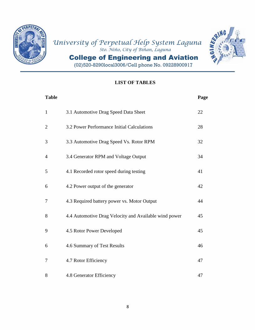
LIST OF TABLES
Table Page
1 3.1 Automotive Drag Speed Data Sheet 22
2 3.2 Power Performance Initial Calculations 28
3 3.3 Automotive Drag Speed Vs. Rotor RPM 32
4 3.4 Generator RPM and Voltage Output 34
5 4.1 Recorded rotor speed during testing 41
6 4.2 Power output of the generator 42
7 4.3 Required battery power vs. Motor Output 44
8 4.4 Automotive Drag Velocity and Available wind power 45
9 4.5 Rotor Power Developed 45
6 4.6 Summary of Test Results 46
7 4.7 Rotor Efficiency 47
8 4.8 Generator Efficiency 47

University of Perpetual Help System Laguna Sto. Niño, City of Biñan, Laguna
College of Engineering and Aviation
(02)520-8290local3006/Cell phone No. 09228900917
9
9 4.7 Overall Efficiency 48
10 4.8 Cost Break down of vertical axis turbine components 49
LIST OF FIGURES
Figure Page
1 1.1 Conceptual Framework 2
2 1.2 Operational Framework 3
3 3.1 Place of the Study 16
4 3.2 Project Development 18
5 3.3 Data for the Month of September 19
6 3.4 Data for the Month of October 20
7 3.5 Data for the Month of November 21
8 3.6 Various Shapes of Blade 25

University of Perpetual Help System Laguna Sto. Niño, City of Biñan, Laguna
College of Engineering and Aviation
(02)520-8290local3006/Cell phone No. 09228900917
10
9 3.7 Initial Blade Design 30
10 3.8 Initial Image Rendering of the Prototype 35
11 4.1 Final Assembly of the Vertical Axis Turbine 40
12 4.2 Voltage and Ampere of the Generator
42
10 4.3 Power Output Curve of the Generator 43

University of Perpetual Help System Laguna Sto. Niño, City of Biñan, Laguna
College of Engineering and Aviation
(02)520-8290local3006/Cell phone No. 09228900917
11
CHAPTER 1
The Problem and its Background
Introduction
Our society consumes each year a huge amount of its energy resources and the
significant part of these energy resources is based from fossil fuels. A large portion of this
energy is being rejected to the ambient in the generation of electricity and the
transportation sectors. This is due to inefficient utilization of energy resources and system
inefficiencies.
Renewable energy such as solar and wind energy has a high potential in reducing
our dependency on the usage of fossil fuels. Wind energy is the rapid growing source of
clean energy worldwide. However, the major problem with this technology is fluctuation
in the source of wind. Recent study shows that there is a near constant source of wind
power on the highways due to turbulence produced by moving vehicles.
Highways/Expressways can provide a considerable amount of wind to drive a
turbine due to high vehicle traffic. Thorough research on wind patterns is required to
determine the average velocity of the wind created by oncoming vehicles. The wind
turbines are placed alongside of the highway, therefore fluid flow from sides of the
highway is considered in the design. Existing streetlights on the highways can be fitted

University of Perpetual Help System Laguna Sto. Niño, City of Biñan, Laguna
College of Engineering and Aviation
(02)520-8290local3006/Cell phone No. 09228900917
12
with these turbines. Additionally, since the source will fluctuate, a storage system for the
power generation is needed to distribute and maintain a constant source of power.
Ideally, the turbine can be used globally as an unlimited power source for
streetlights and other public amenities.
This study focused on designing and applying a renewable energy generating
mechanism to help/aid on lessening consumption of electricity which also generally
reduced the burning of fossil fuel. The general overview of this paper is the potential use
of drag from moving vehicles as a source of energy for generating electricity by the
process of converting it into usable electricity in powering streetlights with low power
consumption.
Conceptual Framework
Fig. 1.1 Conceptual Framework Illustration
Renewable Energy
(Vertical Axis
Turbine)
Alternative Source of
Energy

University of Perpetual Help System Laguna Sto. Niño, City of Biñan, Laguna
College of Engineering and Aviation
(02)520-8290local3006/Cell phone No. 09228900917
13
Fig. 1.1 shows the conceptual framework of the study. The conventional concept
of renewable energy was used in generating electricity. Therefore, using the conceptual
framework, the researchers designed a vertical axis turbine that can be used as an
alternative source of energy. The mechanical energy that produced by the system is
converted to electrical energy by using an energy conversion device.
Operational Framework
Figure 1.2: Operational Framework Illustration
Fig. 1.2 shows the operational framework of the study. The operational
framework shows on how to create a mechanism which helped in reducing electricity
Harnessed Alternative
Source of Energy
Vertical Axis Wind Turbine
Reduced Electricity
Consumption

University of Perpetual Help System Laguna Sto. Niño, City of Biñan, Laguna
College of Engineering and Aviation
(02)520-8290local3006/Cell phone No. 09228900917
14
consumption through vertical axis turbine. The researchers designed and tested a vertical
axis turbine. Different factors such as the design, cost and other variables were
determined. Also, the power output and efficiency of the turbine and the generator were
analyzed.
Objectives of the Study
This study determined whether the harnessed alternative energy by a vertical axis
turbine has an impact on lessening the energy consumption. The purpose of this study is
to propose an alternative source of power by recapturing the turbulence produced by
moving automotive. Specifically, this study aimed to;
1. Design and test a prototype of a vertical axis turbine and
2. Verify its performance by determining the power output of the system.
Assumption of the Study
With the use of the proposed design of the vertical axis turbine, the mechanism
can be used to recapture energy produced by moving automobiles as an alternative source
of electricity for streetlights. Additionally, electricity consumption will be expected to
lessen due to the power produced by the generator of vertical axis turbine.
University of Perpetual Help System Laguna Sto. Niño, City of Biñan, Laguna
College of Engineering and Aviation
(02)520-8290local3006/Cell phone No. 09228900917
15
Scope and Delimitations
The study is limited only on designing and testing vertical axis turbine on a small-
scale basis for generating electricity as an alternative source for streetlights and the
amount of electricity it can produce. This would have a wide range of applications on
fields ranging from household appliances to industrial application, but this study focused
mainly in powering streetlights with low voltage requirement. The researchers limited
their study in the highway of Governors Drive in Carmona, Cavite where the experiment
was conducted.
Significance of the Study
The motivation for designing a highway wind turbine is to contribute towards the
global trend in wind energy production in a feasible way. As technology rapidly grows,
people became unaware of energy consumption.
Mainly, the idea behind this study is to reuse the drag produced by moving cars
into useful and clean electricity for streetlights. The idea is to reduce the amount of
pollution created by burning fossil fuels by introducing a potential source of clean
energy.

University of Perpetual Help System Laguna Sto. Niño, City of Biñan, Laguna
College of Engineering and Aviation
(02)520-8290local3006/Cell phone No. 09228900917
16
This study will also benefit the future researchers who want to focus on the
application of vertical axis wind turbine.
Definition of Terms
The following are the terms used by the researchers in the study. For a common
frame reference, the following are hereby operationally defined:
Vertical Axis Turbine - a machine which converts automotive drag to electrical
energy.
Automotive Drag- turbulence produced by moving vehicles which drive the
Vertical Axis Turbine.
Alternative Energy Source – energy that replaces traditional source of electricity.
Streetlights – a light mounted on a pole connected to the vertical axis turbine.

University of Perpetual Help System Laguna Sto. Niño, City of Biñan, Laguna
College of Engineering and Aviation
(02)520-8290local3006/Cell phone No. 09228900917
17
CHAPTER 2
Review of Related Literature and Studies
This chapter presents the background and various relevant literatures regarding
the concept of vertical axis turbine and its applications. It also includes the synthesis of
the study and the gaps bridged by the study to further understand the research to be done.
Related Literature
Wind Turbines: National and Global Context
According to Motavilli (2005), the wind turbine technology has gone through
many restructuring and changes in the United States. Due to increasing cost of electricity,
California became the first state to develop a power system utilizing wind as a source.
American Wind Energy Association (2002) also stated that the United States wind
industry continued to incline in the 1980s when several states followed. It reached a
plateau because of the electrical industry restructuring and the expiration of the federal
tax credits (United States, Department of Energy, 2008). However, because of increasing
concerns in climate change, technology advancement, and the creation of the market and
policy from the Production Tax Credit (PTC) and state implemented renewable standards,
the wind energy industry is on demand once again.

University of Perpetual Help System Laguna Sto. Niño, City of Biñan, Laguna
College of Engineering and Aviation
(02)520-8290local3006/Cell phone No. 09228900917
18
According to Pryor and Barthelmie (2010), the generated electricity from the
wind contributed over 1 % of the global demand in 2007. In accordance to the recent
report by the Department of Energy of the United States (2008), they found out that the
U. S possesses accessible and affordable resources of wind energy far in excess of the
necessary amount to provide 20 % of the country’s electricity by the year 2030 (Goselin
2007). Greenpeace (2010) states that 10 % of the world power need will be supplied by
wind energy. Pryor and Barthelmie (2010), wind energy ranks second to hydroelectric
power generation in terms of installed capacity among the renewable energy technology
applied in power generation.
According to Global Wind Energy Council (2009), the global wind turbine
installation is on steady climb in the past decade. Currently, the total installed wind
power capacity worldwide is about 121 Giga-watts. Based from the information given by
the American Wind Energy Association (2010), 1000 kilo-Watts of wind power generates
is approximately enough to electrify up to 300 average households.
Global Wind Energy Council (2008) stated that the United Stated surpassed
Germany in terms of global wind turbine installation. United States and Europe are the
leaders in wind power utilization. Developing countries like China are also experiencing
growth in wind industry. One-third of the global wind turbine capacity was developed in

University of Perpetual Help System Laguna Sto. Niño, City of Biñan, Laguna
College of Engineering and Aviation
(02)520-8290local3006/Cell phone No. 09228900917
19
Asia in 2008. Additionally, installed micro wind turbines for household use and other
applications are also experienced by the third-world countries.
According to the article of Saurabh Mahapatra (2016), the Philippines is now the
largest in terms of total installed capacity of wind energy. It has overtaken all of its South
East Asian neighbours. The Philippines now has an operational 400MW of installed wind
turbine capacity, more than anything among other country in the Association of South
East Asian Nation (ASEAN) Region, according to media reports quoting Sen. Juan
Miguel Zubiri who played an important role in the passage of Renewable Energy Law of
2008.
Wind Turbine Production Cost
International Energy Agency (1997) stated that the production cost of wind
turbines dramatically declined by about 20 % in the 1990s. This is due to increasing
number of manufactured wind turbine. Currently, the manufacturing cost of small scale
wind turbine that is connected to the grid almost get twice every 3 years. About a century
ago, during the first year of exploitation of oil a similar cost reduction was accomplished.
Additionally, the Danish Wind Industry Association (2007) states that 50 %reduction of
cost can accomplished by the year 2020. Moreover, based from their White Book, the

University of Perpetual Help System Laguna Sto. Niño, City of Biñan, Laguna
College of Engineering and Aviation
(02)520-8290local3006/Cell phone No. 09228900917
20
European Union Commission said that 30 % of the wind energy cost will be reduced
from 1998 – 2010 (Prehn Morten Surensen, 1997).
The production cost’s comparison of energy among countries, however, is very
hard as it varies. This is due to different structures of taxation, availability of resources
and several other reasons. Additionally, the regulation of the market has an impact on the
prices of electricity among countries.
Wind Turbines Environmental Impact and Reliability
According to T. Ackerman (2000), Wind Power can be considered as
environment friendly, but it is not emission free. The manufacturing of components of
wind turbine such as blades, the tower, the nacelle, the materials exploration, and the
transfer of equipment triggers to the use of energy, therefore, it is still produced
emissions as this energy are fossil fuel based. These are called as indirect emissions.
Additionally, the visual impact and the noise impact of this kind of technology are one
consideration in acceptance of the public, particularly if it is nearly close to human
houses. Reducing the rotational speed and varying the speed are technical means of
decreasing the noise impact. Both the visual and noise impact can also be reduced by
proper installation of wind turbines.

University of Perpetual Help System Laguna Sto. Niño, City of Biñan, Laguna
College of Engineering and Aviation
(02)520-8290local3006/Cell phone No. 09228900917
21
The wind turbine reliability is based on the functionality of its parts under
assigned environment conditions, process of manufacturing, handling, and process of
aging and stress. Chands et al. (1998) had assessed the expert maintenance method. The
reliability of the systems has the possibility to improve. Denson (1998) studied what
causes the electronics system to fail and contributing factors to the failure of the
components of a wind turbine.
Walford (2006) stated in his report in the Sandia National Laboratories that the
critical factor in the success of the wind energy project is the wind turbine system
reliability. Poor reliability directly affects both the project’s stream revenue through
increased operation and maintenance (O&M) costs and reduced availability to generate
power because of the downtime of the turbine.
Wind Turbine Blade Design and Performance Analysis
Young-Tae Lee (2008) in his article “Numerical Study of the Aerodynamic
Performance of a 500 W Darrieus- type vertical axis turbine” studied the performance
and characteristic of a Darrieus-type vertical axis turbine with NACA airfoil blades. The
output of the Darrieus-type vertical axis turbine can be characterized by power and
torque. Various parameters related to vertical axis turbine designs such as helical angle,

University of Perpetual Help System Laguna Sto. Niño, City of Biñan, Laguna
College of Engineering and Aviation
(02)520-8290local3006/Cell phone No. 09228900917
22
chord length, rotor diameter, and pitch angle greatly affects the performance of the
turbine.
Nikam et.al (2015) in his research article “Literature Review on Design and
Development of Vertical Axis Turbine Blade” concluded that the Darrieus-Type turbine
with a NACA airfoil blade produced a maximum power output optimizing the design
parameters.
Loganathan (2012) investigated a domestic scale vertical axis wind turbine
considering blade geometry with semi-circular shaped blades under a range of wind
speeds during operation. A 16-bladed rotor was initially designed and its torques and
angular speeds were measured over a range of wind speeds using a wind tunnel. The
results indicated that the 16-bladed wind turbine can be used for domestic scale wind
power generation. Results show that the wind turbine device has positive effect to
increase the rotor speed to a significant amount. The average rotor speed increased by
about 26% for the 16-bladed rotor

University of Perpetual Help System Laguna Sto. Niño, City of Biñan, Laguna
College of Engineering and Aviation
(02)520-8290local3006/Cell phone No. 09228900917
23
Related Studies
Sharma (2012) assessed the potential of the wind energy on highways. He found
out that the air exerted by the moving vehicles will create air displacement around the
vehicles and along the path ways which will create enough wind speed and air
distribution to rotate the wind turbine. This wind has high pressure and not used.
Joe (2007), student from University of Arizona designed a wind turbine that
captures the wind produced by moving vehicles. These turbines produced approximately
9,600 kWh per year enough to power streetlights and other public amenities.
Ashok et. al (2015) suggested that the proposed model of helical vertical axis
wind turbine can be a good source of renewable energy on highways. The drag produced
by moving vehicles can drive the vertical axis turbine which can be used to generate
electricity. It can be stored in battery and can be utilized for lighting, charging, etc.
A group of mechanical students from Florida International University studied also
about generating electricity using highway wind turbine. They chose Vertical Axis
Turbine due to its advantage over Horizontal Axis Turbine.
El-Samanoudy et.al (2010) said that the vertical axis turbine is preferably chosen
over the horizontal axis turbine such as the shaft of the rotor is put vertically and nearly
located to the ground, as well as the generator and the gearbox. The turbine does not

University of Perpetual Help System Laguna Sto. Niño, City of Biñan, Laguna
College of Engineering and Aviation
(02)520-8290local3006/Cell phone No. 09228900917
24
require to be pointed into the wind. Also there is no need to put a high tower. This makes
the wind turbine easier to maintain if needed. They can be installed on hilltops, on
ridgelines and on the top of buildings and in any areas where the force of the wind is
nearer the ground. Since they are placed lower, they can be used where tall devices are
not allowed by the law. As a result, the use of the vertical axis wind turbine may be
efficient; although of having some disadvantages such as, they cannot cover a large area
of wind. They are not very efficient with regards to extraction of energy because they
operate near the ground where the air flow is turbulent.
Mithun Raj (2015) designed and simulated a vertical axis turbine for highway.
The results showed that the power output also depends on the torque output and the rotor
speeds and hence it is suggested that the selection of turbine should also depend on the
speed at which the vehicle travels normally to increase the efficiency of the turbine. This
proposes placing the VAWTs (Vertical Axis Wind Turbines) at the median of the road so
that the wind from these vehicles moving on the road produces a tangentially acting force
which increases the efficiency of these turbines.

University of Perpetual Help System Laguna Sto. Niño, City of Biñan, Laguna
College of Engineering and Aviation
(02)520-8290local3006/Cell phone No. 09228900917
25
Synthesis of the study
The researchers considered that each of the literature and studies stated in this
project study is similar to the present researches as majority of the materials that used in
this study is the same with the past studies conducted. Only that the design of the
prototype was different compared to the existing one. Through the past studies
conducted, the researchers were able to optimize the design of the vertical axis turbine
driven by automotive drag.
Gap Bridged by the Present Study
After an in-depth analysis and reading done by the researchers, they observed that
there were no studies done about the vertical axis turbine driven by automotive drag
particularly in Carmona, Cavite as the proposed site of installation.
Based on the gap identified, the researchers adapted it as a development of a
vertical axis turbine driven by automotive drag in Governor’s Drive Barangay Bancal,
Carmona, Cavite as well as an improvement of the existing design.

University of Perpetual Help System Laguna Sto. Niño, City of Biñan, Laguna
College of Engineering and Aviation
(02)520-8290local3006/Cell phone No. 09228900917
26
Chapter 3
Research Methodology
This chapter contains elaboration on the research design and its components,
which are methods of research, sources of data, test procedures, project development and
the evaluation criteria on testing.
Research Locale
Fig. 3.1Place of the Study

University of Perpetual Help System Laguna Sto. Niño, City of Biñan, Laguna
College of Engineering and Aviation
(02)520-8290local3006/Cell phone No. 09228900917
27
The previous figure above shows the research locale where the study was
conducted. The study was conducted along the highway of Governor’s Drive located in
Barangay Bancal, Carmona Cavite because it is the easiest and nearest possible site for
the researchers. The highway is a 4-way lane and constant number of vehicles is passing
by day and night.
Research Design
The researchers employed experimental research design. Series of trials was done
in gathering automotive drag speed on the location performed to determine the design for
the system. Using the design wind speed, each component was chosen based on the
design criteria.
The researchers had undergone preliminary researches and significant amount of
consultations with professionals. The knowledge acquired was used to design the
mechanism in the form of vertical axis turbine that generated electrical power from drag
produced by moving automotive.
The relevant aspect in the design and construction of the vertical axis turbine is its
ability to provide an alternative energy source for streetlights. The overall efficiency of
the system will be measured on actual testing of its power output.

University of Perpetual Help System Laguna Sto. Niño, City of Biñan, Laguna
College of Engineering and Aviation
(02)520-8290local3006/Cell phone No. 09228900917
28
Block Diagram
Fig. 3.2 Project Development
Fig. 3.2 shows how the system works. Vertical axis wind turbines have their main
rotor shaft set vertically. The generator and belt drive are usually set below and the rotor
blades rotate around the shaft. As the vehicles passed by, it produces turbulence which
drags the rotor blades and spin around the main shaft. The spinning shaft drives the
Generator Battery
Automotive
Drag Turbine Blades Rotor Shaft
Power
Transmission
Streetlights

University of Perpetual Help System Laguna Sto. Niño, City of Biñan, Laguna
College of Engineering and Aviation
(02)520-8290local3006/Cell phone No. 09228900917
29
3.2
4.54
4.8
0
1
2
3
4
5
6
1st week 2nd week 3rd week 4th week
Auto
moti
ve
Dra
g S
pee
d (
m/s
)
September
Automotive Drag Speed
generator and electricity is generated, the electricity will be regulated to charge a lead
acid battery and directly used the direct current which will now power the streetlights.
Data Gathering Procedure
The researchers proceed to Governor’s Drive Barangay Bancal, Carmona, Cavite
which was the test location for data gathering used for designing of the prototype. The
parameters required are the automotive drag velocity measured in m/s. A digital
anemometer was used to measure the automotive drag speed on the location. One trial per
week was done at different possible testing sites in the location for the month of
September, October, and November.
Figure 3.3 Data for the month of September

University of Perpetual Help System Laguna Sto. Niño, City of Biñan, Laguna
College of Engineering and Aviation
(02)520-8290local3006/Cell phone No. 09228900917
30
Figure 3.3 shows the data gathered for the month of September. The data shows
that the automotive drag speed ranges from 3.2 m/s to 4.8 m/s.
Figure 3.4Data for the month of October
Figure 3.4 shows the data gathered for the month of October. The automotive drag
speed gathered was much higher than the data gathered for the month of September. The
data ranges from 5 m/s to 6.4 m/s.
65.5
6.4
5
0
1
2
3
4
5
6
7
1st week 2nd week 3rd week 4th week
Auto
moti
ve
Dra
g S
pee
d (
m/s
)
October
Automotive Drag Speed

University of Perpetual Help System Laguna Sto. Niño, City of Biñan, Laguna
College of Engineering and Aviation
(02)520-8290local3006/Cell phone No. 09228900917
31
4.3
3.62.9
3.9
0
1
2
3
4
5
1st week 2nd week 3rd week 4th week
Auto
moti
ve
Dra
g S
pee
d (
m/s
)
November
Automotive Drag Speed vs Time
Figure 3.5Data for the month of November
The figure above shows the data gathered for the month of November. There is a
little variation on the data gathered as compared to the data for the month of September
and October.

University of Perpetual Help System Laguna Sto. Niño, City of Biñan, Laguna
College of Engineering and Aviation
(02)520-8290local3006/Cell phone No. 09228900917
32
Month Drag Speed (m/s)September 1st Week 3.2
September 2nd Week 4.5
September 3rd Week 4
September 4th Week 4.8
October 1st Week 6
October 2nd Week 5.5
October 3rd Week 6.4
October 4th Week 5
November 1st week 4.3
November 2nd week 3.6
November 3rd week 2.9
November 4th week 3.9
Average 4.51
Summary of Data Gathering
Table 3.1 Automotive Drag Speed Data Sheet
Table 3.2 shows the data sheet for the automotive drag speed. The data gathering
was done at different time frame per week. The gathered data were used as basis for the
computation of the design consideration of the prototype. Automotive Drag speed from 1
to 2 meters below the ground was obtained.

University of Perpetual Help System Laguna Sto. Niño, City of Biñan, Laguna
College of Engineering and Aviation
(02)520-8290local3006/Cell phone No. 09228900917
33
Design Consideration
The following were considered in the design of the prototype.
A. Speed of the Automotive drag
The speed of the automotive drag is very much essential for the production of the
electricity in the vertical axis turbine. Minimal amount of automotive drag will be
able to rotate the turbine.
B. The tower height and design
The tower for the vertical axis turbine will be kept little to obtain whole air
density from oncoming vehicles. The researchers should also concentrate on the design of
the tower because it should be able to withstand for maximum wind speed and also its
own weight.
C. The Design of the Blade
The most complicated part of the design is the blade because they must be
propelled by automotive drag in any direction. The blade of the vertical axis turbine
must be angled and curved so that bigger surface area is exposed to the automotive

University of Perpetual Help System Laguna Sto. Niño, City of Biñan, Laguna
College of Engineering and Aviation
(02)520-8290local3006/Cell phone No. 09228900917
34
drag from the moving vehicles. The blade must also be lightweight as possible so that
it can drive the generator. The central part is a hollow shaft wherein the turbine blades
will be attached. It must be large enough to fit with the size of the streetlights. As
discussed earlier the shape of the wind mill blades is the important one if one could
place an efficient design of a blade then the efficiency of the windmill will be
increased.
The various windmill shapes are as follows:
1) Flat, unmodified blade surface
2) Wing shape with one leading edge
3) Both edges tapered to a thin line
4) Both edges leading blade

University of Perpetual Help System Laguna Sto. Niño, City of Biñan, Laguna
College of Engineering and Aviation
(02)520-8290local3006/Cell phone No. 09228900917
35
A drawing of tested shape blades are provided below.
Figure 3.6 Various Shapes of Blade
Designing the Vertical Axis Turbine
Choosing Turbine Size
The swept area is the section of air that encloses the turbine in its movement, the
shape of the swept area depends on the rotor configuration, this way the swept area of a
horizontal axis wind turbine is circular shaped while for a straight-bladed vertical axis
wind turbine the swept area has a rectangular shape and is calculated using:

University of Perpetual Help System Laguna Sto. Niño, City of Biñan, Laguna
College of Engineering and Aviation
(02)520-8290local3006/Cell phone No. 09228900917
36
S = DL
where: S is the swept area (m3)
D is the rotor radius (m),
and, L is the blade length (m).
The swept area limits the volume of air passing by the turbine. The rotor converts
the energy contained in the wind in rotational movement so as bigger the area, bigger
power output in the same wind conditions.
Power and power coefficient
The following formulas will be utilized to design the vertical axis turbine size.
P = ½ρAV3
where P; Power available extracted from the wind, V is the velocity of the wind (m/s) and
ρ is the air density (kg/m3), the reference density used its standard sea level value (1.225
kg/m3 at 15ºC), for other values the source (Aerospaceweb.org, 2005) can be consulted.
Note that available power is dependent on the cube of the airspeed.

University of Perpetual Help System Laguna Sto. Niño, City of Biñan, Laguna
College of Engineering and Aviation
(02)520-8290local3006/Cell phone No. 09228900917
37
The power coefficient (Cp) is the power extracted divided by the power available
Cp= Power Extracted
½ρAV3
The maximum value for the power coefficient is called “Betz Limit”
Cp max = 0.5926 or 59.26%
The maximum power that can be extracted from a given wind stream is defined
by what is known as the Betz limit, therefore, the power extracted is calculated by the
following equation
Power Extracted = ½ (Cp)ρAV3
V= Automotive Drag Velocity (m/s)
ρ = fluid Density
Cp value represents the part of the total available power that is actually taken
from wind, which can be understood as its efficiency.

University of Perpetual Help System Laguna Sto. Niño, City of Biñan, Laguna
College of Engineering and Aviation
(02)520-8290local3006/Cell phone No. 09228900917
38
Table 3.2 Power Performance initial calculations
Table 3.3 shows what were the initial estimated performance of the wind turbine,
the power coefficient had been estimated analysing the data taken from similar market
wind turbines. The researcher made an assumption of 20% turbine efficiency. It shows
that based on 1.04 m2 swept area, the turbine can produce a shaft power of 12.14 watts at
4.51 m/s of average automotive drag velocity.
Inputs
Over-all Diameter 1.3 meter *chosen for the fitting location
Blade Length 0.8 meter
Automotive Drag Velocity 4.51 m/s *Based on Ave. automotive Drag Speed
Power Coefficient 59.26% *Constant Cp for wind (Betz Limit)
0.2 *Estimated Cp for the turbine
*Ranges 15% to 35% for small turbine
Outputs
Turbine Swept Area
Power Available in the wind 60.68 watts
Power produce by the turbine 12.14 watts
ESTIMATED POWER CALCULATIONS

University of Perpetual Help System Laguna Sto. Niño, City of Biñan, Laguna
College of Engineering and Aviation
(02)520-8290local3006/Cell phone No. 09228900917
39
Choosing the Number of blades
The more blades there are on a wind turbine, the higher will be the torque (the force
that creates rotation) and the slower the rotational speed (because of the increased drag
caused by wind flow resistance). But turbines used for generating electricity need to
operate at high speeds, and actually do not need much torque. So, the fewer the number
of blades, the better suited the system is for producing power.Theoretically, a one-bladed
turbine is the most aerodynamically efficient configuration. However, it is not very
practical because of stability problems. Turbines with two blades offer the next best
design, but are affected by a wobbling phenomenon similar to gyroscopic precession.
Since a wind turbine must always face into the wind, the blades will have to change
their direction vertically when there is a shift in wind direction. This is referred to as
yawing. In the case of a two-bladed system, when the blades are vertical (i.e., in line with
the tower and the axis of rotation) there is very little resistance to the yawing motion.
But when the two blades are in the horizontal position, the blades span a greater
distance from the axis of rotation and so experience maximum resistance to yawing
(notice how a spinning figure skater slows down when they bring their arms away from

University of Perpetual Help System Laguna Sto. Niño, City of Biñan, Laguna
College of Engineering and Aviation
(02)520-8290local3006/Cell phone No. 09228900917
40
their body). As a result, the yawing motion starts and stops twice per revolution, and this
leads to stress on the turbine due to blade chattering.
On the other hand, a turbine with three blades has very little vibration or chatter.
This is because when one blade is in the horizontal position; its resistance to the yaw
force is counter-balanced by the two other blades. So, a three-bladed turbine represents
the best combination of high rotational speed and minimum stress.
Top View Isometric View
Figures3.7 Initial Blade Design
The above figure shows the initial design of the blade of the wind turbine
rendered using Solidworks. The design is based on a wing shape with one leading edge,

University of Perpetual Help System Laguna Sto. Niño, City of Biñan, Laguna
College of Engineering and Aviation
(02)520-8290local3006/Cell phone No. 09228900917
41
and to be made as lightweight as possible so that it can be able to rotate smoothly. The
arms were support by circular flat bar to maintain the stability of the turbine when
running.
Theoretical RPM computation
Considering the automotive drag speed islowest wind speed from table 3.2.
𝜔 𝑇𝑆𝑅 𝑥 𝑣
𝑑
Assuming a Tip Speed Ratio of 2
𝜔 (2)𝑥 2 9 /𝑠
3
𝜔 62 𝑟𝑎𝑑/𝑠
𝑛𝑟 6
2𝜋𝑥 𝜔
𝑛𝑟 6
2𝜋𝑥 62 𝑟𝑎𝑑/𝑠
𝑛𝑟 𝟒𝟑 𝒓𝒑𝒎

University of Perpetual Help System Laguna Sto. Niño, City of Biñan, Laguna
College of Engineering and Aviation
(02)520-8290local3006/Cell phone No. 09228900917
42
Drag Speed (m/s) Rotor RPM2.0 m/s 29rpm
2.5 m/s 37rpm
3.0m/s 44rpm
3.5 m/s 51rpm
4.0 m/s 59rpm
4.5 m/s 66rpm *Theoretical RPM output based on ave. Drag speed
5.0 m/s 73rpm
5.5 m/s 81 rpm
6.0 m/s 88rpm
6.5 m/s 95rpm
7.0 m/s 103 rpm
Table 3.3 Automotive Drag Speed Vs. Rotor RPM
Table Above shows the theoretical rotor RPM expected at a certain drag speed.
As speed goes up, the rpm of the rotor becomes faster.
Motor minimum RPM requirement
The motor which is used as a generator provides 21 volts and 2-A current at 3150
rpm. Its volt to rpm ratio is 1/150V/RPM (21 divided by 3150). The researchers aim is to
charge a lead acid motorcycle battery with terminal voltage of 2.5 volts. The battery will
charge at a minimum voltage of 2.5 volts. The motor is used as a generator and it is not
100 % efficient unlike the generator. It is roughly 85 % efficient as the generator.

University of Perpetual Help System Laguna Sto. Niño, City of Biñan, Laguna
College of Engineering and Aviation
(02)520-8290local3006/Cell phone No. 09228900917
43
Therefore,
𝐺𝑒𝑛𝑒𝑟𝑎𝑡𝑜𝑟 𝑅𝑃𝑀( 𝑖𝑛) min 𝑣𝑜𝑙𝑡𝑎𝑔𝑒 𝑟𝑒𝑞𝑢𝑖𝑟𝑒𝑑
(𝑣𝑜𝑙𝑡𝑠
𝑟𝑝𝑚) ( 𝑜𝑡𝑜𝑟 𝑒𝑓𝑓𝑖𝑐𝑖𝑒𝑛𝑐𝑦)
𝐺𝑒𝑛𝑒𝑟𝑎𝑡𝑜𝑟 𝑅𝑃𝑀( 𝑖𝑛) 2 5𝑣𝑜𝑙𝑡𝑠
(1
150)𝑣𝑜𝑙𝑡𝑠
𝑟𝑝𝑚( 8)
𝐺𝑒𝑛𝑒𝑟𝑎𝑡𝑜𝑟 𝑅𝑃𝑀( 𝑖𝑛) 𝟒𝟒𝟏 𝟏𝟕
Hence, the motor which is used as a generator must at least rotate at
approximately 441 rpm to produce 2.5 volts to be able to charge the motorcycle lead acid
battery.
Choosing Speed Ratio
The generator must turn at more than 450 rpm at lowest automotive drag speed of
2.9 m/s to be able to produce a voltage greater than 2.5 volts to be able to charge a lead
acid battery with terminal voltage of 2.5 volts. Thus;
𝑆𝑝𝑒𝑒𝑑 𝑟𝑎𝑡𝑖𝑜 𝑁(𝑔𝑒𝑛)
𝑁(𝑟𝑜𝑡𝑜𝑟)

University of Perpetual Help System Laguna Sto. Niño, City of Biñan, Laguna
College of Engineering and Aviation
(02)520-8290local3006/Cell phone No. 09228900917
44
Rotor RPM Generator RPM Theoretical Voltage Output
29rpm 464 2.62
37rpm 592 3.35
44rpm 704 3.98
51rpm 816 4.62
59rpm 944 5.35
66rpm 1056 5.98
73rpm 1168 6.62
81 rpm 1296 7.34
88rpm 1408 7.98
95rpm 1520 8.61
103 rpm 1648 9.34
𝑆𝑝𝑒𝑒𝑑 𝑟𝑎𝑡𝑖𝑜 5 𝑟𝑝
29 𝑟𝑝
𝑺𝒑𝒆𝒆𝒅 𝒓𝒂𝒕𝒊𝒐 𝟏𝟓 𝟓𝟏
The researchers provide a pulley with a speed ratio of approximately 16.
𝑆𝑝𝑒𝑒𝑑 𝑟𝑎𝑡𝑖𝑜 𝐷𝑟𝑜𝑡𝑜𝑟 𝑝𝑢𝑙𝑙𝑒𝑦
𝐷𝑔𝑒𝑛𝑒𝑟𝑎𝑡𝑜𝑟 𝑝𝑢𝑙𝑙𝑒𝑦
𝑆𝑝𝑒𝑒𝑑 𝑟𝑎𝑡𝑖𝑜 2 𝑖𝑛
3/ 𝑖𝑛
𝑺𝒑𝒆𝒆𝒅 𝒓𝒂𝒕𝒊𝒐 𝟏𝟔
Table 3.4 Generator rpm and voltage output
The table above shows the tabulated data for theoretical voltage output of the
motor for a certain generator RPM with 85 % motor efficiency assumption.

University of Perpetual Help System Laguna Sto. Niño, City of Biñan, Laguna
College of Engineering and Aviation
(02)520-8290local3006/Cell phone No. 09228900917
45
Fig. 3.8 Initial image rendering of the prototype
Above figure shows the preliminary design of the vertical axis turbine. The
researchers used the initial value for the estimated calculations made above that fit within
the design criteria tobe able to fabricate the prototype. Efficient placement is necessary to
harvest the maximum energy from automotive drag.

University of Perpetual Help System Laguna Sto. Niño, City of Biñan, Laguna
College of Engineering and Aviation
(02)520-8290local3006/Cell phone No. 09228900917
46
Materials and Specification
Now that the initial calculations have been made and the design was already
rendered, it is now time for the researchers to find and prepare the necessary and
available materials that is needed for the crafting of the wind turbine. The following
materials have been prepared according to the desired turbine design:
Pole -1 piece 8 ft. (height) by 48 cm (outside diameter) Galvanized Iron Pipe.
Blade arm and support – 1 piece 20 ft. length by ¾ inch width flat bar
Bearing – 2 piece ARB 6210-2rs 50 cm inside diameter by 90 cm outside
diameter by 20 cm overall width sealed ball bearing.
Blade – 1 whole piece aluminum sheet.
Base – 20 cm by 17 cm steel plate.
Motor – 21 volt dc supply at 3150rpm, 2A current output
12 volt lead acid motorcycle battery
Blocking Diode, Connecting wires, and Light bulb
Apart from the parts said above, certain materials and components are required
during main assembly of Vertical Axis Wind Turbine, such as aluminum strips, threaded
rod, bolts for fastening, rivets.

University of Perpetual Help System Laguna Sto. Niño, City of Biñan, Laguna
College of Engineering and Aviation
(02)520-8290local3006/Cell phone No. 09228900917
47
Transmission system:
The belt and pulley system is used as the transmission system in this turbine
The gear ratio of 1:16 has been used.
Fabrication Sequence
Fabrication of vertical axis wind turbine consists of different parts which are
needed to be fabricated as parts of main assembly. Following are the parts of VAWT, to
be fabricated:
Blades- fabrication of blade consists of aluminum blades, flat bars,
aluminum sheet circular cross section support for arm support. The cut
metal sheet is coupled into the skeletal frame by rivets to form the design
curve of the blades.
Pole – the pole served as the support for the wind turbine, also it served as
shaft were the bearing will be attached.
Base - the base aims at providing a strong support to the turbine. Hence,
have flexibility in design in accordance with supporting strength.

University of Perpetual Help System Laguna Sto. Niño, City of Biñan, Laguna
College of Engineering and Aviation
(02)520-8290local3006/Cell phone No. 09228900917
48
Testing Procedure
In order to test the effectiveness of the system, series of experiments and trials
will be conducted in measuring revolution per minute of the rotor, power output of the
generator and the overall efficiency of the system.
The actual revolution per minute of the rotor was measured to know the
performance of the system. Available wind power will be computed by the basic wind-
power equation that is used for estimating extractable power from any moving fluid mass.
Shaft power generated on the rotor will be calculated by
𝑃𝑠 2𝜋𝑇𝑛
6
𝑇 𝐹𝑤 𝑥 𝑟
Where, 𝑃𝑠 = Shaft Power, T = Torque, 𝐹𝑤 = Wind load and n = actual RPM
The power output is the actual reading of power generated by the system and will
be measured by the voltage output multiply by its current.

University of Perpetual Help System Laguna Sto. Niño, City of Biñan, Laguna
College of Engineering and Aviation
(02)520-8290local3006/Cell phone No. 09228900917
49
The effectiveness of the turbine will be evaluated through its overall efficiency
which is its power generated over the wind power available.
𝑂𝑣𝑒𝑟𝑎𝑙𝑙 𝑒𝑓𝑓𝑖𝑐𝑖𝑒𝑛𝑐𝑦 𝑃𝑜𝑤𝑒𝑟 𝑔𝑒𝑛𝑒𝑟𝑎𝑡𝑒𝑑
𝑊𝑖𝑛𝑑 𝑝𝑜𝑤𝑒𝑟 𝑥 %

University of Perpetual Help System Laguna Sto. Niño, City of Biñan, Laguna
College of Engineering and Aviation
(02)520-8290local3006/Cell phone No. 09228900917
50
CHAPTER 4
Presentation, Analysis and Interpretation of Data
This chapter includes presentation, analysis and interpretation of data which were
drawn from the actual testing of the vertical axis turbine along the highway of Governor’s
Drive Barangay Bancal, Carmona, Cavite. The results of the study are presented in
tabulation and graph form and were interpreted by the researchers.
System Specification
Figure 4.1 Final Assembly of the Vertical Axis Turbine

University of Perpetual Help System Laguna Sto. Niño, City of Biñan, Laguna
College of Engineering and Aviation
(02)520-8290local3006/Cell phone No. 09228900917
51
Test Results
Data have been collected at the test location alongside of the highway. The
variation in the automotive drag velocity results in the changes in the rotation of the
blades rotor. The number of successful revolution of the rotor is counted per minute. The
relevance of the rotor rpm is to know the required rpm of the generator needed for the
system to generate a certain power output. The table below gives the actual data collected
in the highway for rotor rpm. Four trials were done during the testing of the prototype at a
random time. The rotational speed of the rotor was recorded.
Trial Average Drag Velocity
(m/s)
Rotor Speed
(RPM)
1 4.90 72
2 3.89 57
3 4.01 59
4 4.42 65
Table 4.1Recorded rotor speed during testing
Using the recorded rotor speed, the researchers used the obtained speed ratio of 16
to be able to determine the rotational speed of the generator. Table 4.2 presents the data
for the output produce by the generator. The generator output is obtained by multiplying
the voltage and current reading in the digital multi tester during the test.

University of Perpetual Help System Laguna Sto. Niño, City of Biñan, Laguna
College of Engineering and Aviation
(02)520-8290local3006/Cell phone No. 09228900917
52
Rotor
Speed
(RPM)
Generator
(RPM)
Measured Voltage
(V)
Measured Current
(A)
Generator Output
(W)
72 1152 6.42 0.58 3.72
57 912 4.92 0.483 2.37
59 944 5.23 0.497 2.59
65 1040 5.55 0.528 2.93
Table4.2 Power output of the generator
Using the recorded rotor speed, the researchers used the obtained speed ratio of 16
to be able to determine the rotational speed of the generator. Table 4.2 presents the data
for the output produce by the turbine generator. The generator output is obtained by
multiplying the voltage and current reading in the digital multi tester during the test.
Figure 4.2 Voltage and Ampere of the Generator
6.42
4.92 5.235.55
0.58
0.483 0.4970.528
0
0.1
0.2
0.3
0.4
0.5
0.6
0.7
0
1
2
3
4
5
6
7
1152 912 944 1040
Am
per
e (A
)
Volt
age
(V)
Generator RPM
Generator RPM vs Voltage
Voltage (V) Current (A)

University of Perpetual Help System Laguna Sto. Niño, City of Biñan, Laguna
College of Engineering and Aviation
(02)520-8290local3006/Cell phone No. 09228900917
53
3.72
2.372.59
2.93
0
0.5
1
1.5
2
2.5
3
3.5
4
1152 912 944 1040
Gen
erat
or
Pow
er (
W)
Generator (rpm)
Generator RPM vs Power
`
Figure 4.3 Power Output Curve of the Generator
The graph given in the Figure 4.2 and Figure 4.3 gives the actual data collected in
highway at different rotational speed of the turbine blade. The generator rpm is relevant
in the rotors rpm as the output of the system is depending on its current speed on the test.
As the rotational speed of the rotor becomes higher, the output power of the generator
also increases. The highest recorded power output of the turbine generator was 3.57
watts, hence, it can produce a 3.57 watt-hour if it is running on an hour.
University of Perpetual Help System Laguna Sto. Niño, City of Biñan, Laguna
College of Engineering and Aviation
(02)520-8290local3006/Cell phone No. 09228900917
54
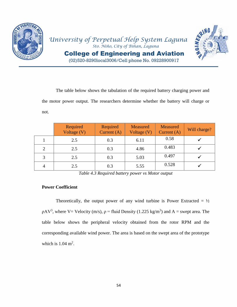
The table below shows the tabulation of the required battery charging power and
the motor power output. The researchers determine whether the battery will charge or
not.
Required
Voltage (V)
Required
Current (A)
Measured
Voltage (V)
Measured
Current (A) Will charge?
1 2.5 0.3 6.11 0.58
2 2.5 0.3 4.86 0.483
3 2.5 0.3 5.03 0.497
4 2.5 0.3 5.55 0.528
Table 4.3 Required battery power vs Motor output
Power Coefficient
Theoretically, the output power of any wind turbine is Power Extracted = ½
ρAV3, where V= Velocity (m/s), ρ = fluid Density (1.225 kg/m3) and A = swept area. The
table below shows the peripheral velocity obtained from the rotor RPM and the
corresponding available wind power. The area is based on the swept area of the prototype
which is 1.04 m2.

University of Perpetual Help System Laguna Sto. Niño, City of Biñan, Laguna
College of Engineering and Aviation
(02)520-8290local3006/Cell phone No. 09228900917
55
Peripheral Velocity (m/s) Wind Power (watts)
4.90 74.94
3.89 37.49
4.01 41.07
4.42 55
Table 4.4 Automotive Drag Velocity and Available wind power
Practically, with an average of 4.16m/s automotive drag velocity rotating a
turbine at 72 rpm which accounts for 74.94 watts of available wind power according to
the equation. Hence one can obtain an output of 35-75 watts with an automotive drag
speed of. 3.9-5.0 m/s.
The next table presents the tabulation of the power input of the turbine. Shaft
power generated on the rotor will be calculated by the formula; 𝑃𝑠 𝜋𝑇𝑛
60, where 𝑃𝑠 is the
shaft power, T = Torque and n is the rotational speed of the shaft of the turbine rotor.𝑇
𝐹𝑥𝐷 1
𝜌𝑣 𝐷(𝑝𝑢𝑙𝑙𝑒𝑦).𝜌 225: 𝐷 3 8
Velocity
(m/s)
Torque
(N.m)
Rotor Power
(watts)
4.90 4.482 33.79
3.89 2.825 16.86
4.01 3.001 18.54
4.42 3.647 24.82
Table 4.5 Rotor power developed

University of Perpetual Help System Laguna Sto. Niño, City of Biñan, Laguna
College of Engineering and Aviation
(02)520-8290local3006/Cell phone No. 09228900917
56
Evaluation Results
Table 4.5 shows the summary of the results for the actual test of the system. All
categories are dependent on the rate of the automotive drag speed at the time of the test.
As the automotive drag speed goes up, the rotor rotational speed will increase and the
output of the whole system will simultaneously increase.
Drag
Velocity
(m/s)
Wind power
(W)
Rotor
RPM
Rotor power
(W)
Generator
(RPM)
Generator
Output
(W)
4.90 74.94 72 33.79 1152 3.72
3.89 37.49 57 16.86 912 2.37
4.01 41.07 59 18.54 944 2.59
4.42 55 65 24.82 1040 2.93
Table 4.6 Summary of test results
Efficiency of the System
The rotor efficiency of the can be calculated using the formula:
Rotor 𝑒𝑓𝑓𝑖𝑐𝑖𝑒𝑛𝑐𝑦 𝑅𝑜𝑡𝑜𝑟 𝑝𝑜𝑤𝑒𝑟
𝑊𝑖𝑛𝑑 𝑝𝑜𝑤𝑒𝑟 𝑥 % . Table 4.5 shows the tabulation for the
mechanical efficiency of the system.

University of Perpetual Help System Laguna Sto. Niño, City of Biñan, Laguna
College of Engineering and Aviation
(02)520-8290local3006/Cell phone No. 09228900917
57
Wind power
(W)
Rotor power
(W) Rotor Efficiency
74.94 33.79 45.08%
37.49 16.86 44.97%
41.07 18.54 45.14%
55 24.82 45.12%
Table 4.7 Rotor Efficiency
The generator efficiency of the turbine can be calculated using the formula:
Generator 𝑒𝑓𝑓𝑖𝑐𝑖𝑒𝑛𝑐𝑦 𝐺𝑒𝑛𝑒𝑟𝑎𝑡𝑜𝑟 𝑂𝑢𝑡𝑝𝑢𝑡
𝑅𝑜𝑡𝑜𝑟 𝑃𝑜𝑤𝑒𝑟 𝑥 %. Table 4.6 shows the tabulation for
the generator efficiency of the system.
Rotor power
(W)
Generator Output
(W) Generator Efficiency
33.79 3.72 11%
16.86 2.37 14.06%
18.54 2.59 13.97%
24.82 2.93 11.80%
Table 4.8 Generator Efficiency
The efficiency of the turbine can be calculated using the formula:
O𝑣𝑒𝑟𝑎𝑙𝑙 𝑒𝑓𝑓𝑖𝑐𝑖𝑒𝑛𝑐𝑦 𝑃𝑜𝑤𝑒𝑟 𝑔𝑒𝑛𝑒𝑟𝑎𝑡𝑒𝑑
𝑊𝑖𝑛𝑑 𝑝𝑜𝑤𝑒𝑟 𝑥 % . The table below shows the tabulation
for the overall efficiency of the system.

University of Perpetual Help System Laguna Sto. Niño, City of Biñan, Laguna
College of Engineering and Aviation
(02)520-8290local3006/Cell phone No. 09228900917
58
Wind power (W) Generator Output
(W) Overall Efficiency
74.94 3.72 4.96 %
37.49 2.37 6.32 %
41.07 2.59 6.31 %
55 2.93 5.33 %
Table 4.9 Overall System Efficiency

University of Perpetual Help System Laguna Sto. Niño, City of Biñan, Laguna
College of Engineering and Aviation
(02)520-8290local3006/Cell phone No. 09228900917
59
Quantity Element Unit Cost (PhP) Total Cost (PhP)
1 8 Ft. G.I Pipe PHP 350.00 PHP 350.00
1 D.C Motor PHP 800.00 PHP 800.00
2 Ball Bearings PHP 173.00 PHP 346.00
1 Steel Plate PHP 315.00 PHP 315.00
1 Flat Bar PHP 90.00 PHP 90.00
2 Pulley PHP 520.00 PHP 520.00
1 Aluminum Sheet PHP 580.00 PHP 580.00
1 Blocking Diode PHP 50.00 PHP 50.00
1 LED Light Bulb PHP 340.00 PHP 340.00
1 Belt On hand PHP 0.00
1 Battery On hand PHP 0.00
Connecting Wires On hand PHP 0.00
Total Material Cost PHP 3,391.00
Labor Cost PHP 7,000.00
Miscellaneous And PHP 1,500.00
Others
Total Cost PHP 11,891.00
Breakdown of Expenses
Cost Analysis
Table 4.8 Cost Break down of vertical axis turbine components
The figure above shows the breakdown of cost in the fabrication of the vertical
axis turbine. The researchers do not have sponsors for this project therefore the costs is
divided among the group members. Actual cost of all the parts of the turbine including
the laborer cost and other expenses are listed in the above figure. To save money, the
researchers bought some of the parts in junkshop and some other parts are fabricated such
as the wind turbine blade, the housing of the bearings.

University of Perpetual Help System Laguna Sto. Niño, City of Biñan, Laguna
College of Engineering and Aviation
(02)520-8290local3006/Cell phone No. 09228900917
60
CHAPTER 5
Summary, Conclusions, and Recommendation
This chapter presents the summary of the research work undertaken, the
conclusions drawn from the data gathered and the recommendations made as outgrowth
of this study. This study is on the designing and testing of a vertical axis turbine driven
by automotive drag as an alternative energy source for streetlights.
Findings
In this study, a small scale vertical axis turbine was designed and tested for the
purpose of recapturing the turbulence produce by moving vehicles in the highway to
serve as an alternative source of energy for streetlights. The prototype which was
relatively simple and cheap to construct was in essence the main criteria for wind turbine
selection. A Darrieus H-type rotor was selected as it best fitted the design criteria. After
conducting the experiments, the salient findings of the study are as follows:
The minimum rpm requirement for the rotor was attained to be able to run the
generator and produce power. However, it is quite relatively low.
Based from the design of the prototype, at an average of 3.6 to 5.0 m/s, the
amount of wind power that it can extract is from 30-75 watts.

University of Perpetual Help System Laguna Sto. Niño, City of Biñan, Laguna
College of Engineering and Aviation
(02)520-8290local3006/Cell phone No. 09228900917
61
The mechanical efficiency of the turbine is almost at an average of 45%.
The output power of the generator reach up to 3.5 watts which is enough to charge
the lead acid motorcycle battery.
The overall efficiency of the turbine from wind power to generator power output
peak up to 6.47%.
Conclusion
The results collected so far in designing and testing the vertical axis turbine which
recaptures energy from oncoming vehicles are very encouraging and has a high potential
in reducing our dependency on the use of electricity which majority comes from fossil
fuel. Using the obtained data, a vertical axis turbine is designed and tested alongside the
highway of Governor’s Drive, Barangay, Bancal, Carmona, Cavite. Although one
turbine cannot provide enough energy, a collective number of these turbines can generate
large amount of usable energy that can be used to power a typical streetlights. The
location of installing these wind turbines is also a great factor. It is an advantage if these
turbines are placed wherein there is high volume of passing vehicles day and night like
expressways as it gives more opportunity for high turbulence. If this technology was
improved and will be implemented soon, highways can be lightened without the use of

University of Perpetual Help System Laguna Sto. Niño, City of Biñan, Laguna
College of Engineering and Aviation
(02)520-8290local3006/Cell phone No. 09228900917
62
conventional energy and we will be able to reduce large amount of non-renewable energy
and also our environment will benefit from it.
Recommendations
A small scale prototype of vertical axis turbine was design and tested using the
obtained parameters. The turbine is fabricated using available materials that fit the design
criteria. From the test result obtained during the experiment, it is noted that the prototype
can extract up to 75 watts of wind power for an average automotive drag speed of 4.16
m/s or approximately 15 kph and which can be eventually increased. The following
measures can be recommended by the researchers for the scope of future work:
Optimizing the design of the blade for trapping and recapturing more turbulence.
Using a generator, instead of motor that generates a higher voltage at a lower rpm.
Maximizing swept area of the blade that will fit the highway as it gives a higher
Tip Speed Ratio.
Incorporating a solar panel to the design to increase its efficiency.
A gear mechanism with high speed ratio is much better as it gives lesser loss in
transmission and increases the rpm of the generator, therefore, power output can
be higher.
More accurate fabrication of the structure of the turbine for better functionality.

University of Perpetual Help System Laguna Sto. Niño, City of Biñan, Laguna
College of Engineering and Aviation
(02)520-8290local3006/Cell phone No. 09228900917
63
References
Ackerman, T. (2000). Wind energy technology and current status, a review, Elsevier
Sciencep. 351
Champagnie, B. et al (2013). Highway Wind Turbines, EML 4905 Senior Design
Project, Florida International Univesity
Chands, P.K., Tokekar, S.K. (1998). Expert Based maintenance: A study of its
effectiveness, IEEE Trans Reliab, Vol. 47, p. 95-97.
Denson, W. (1998). The history of reliability prediction, failure causes for electronic
systems, IEEE Trans Reliab, Vol. 47, p. 325.
Joe Archinect. Retrieved March 15, 2013, from Arizona State University
http://archinect.com/blog/article/21451130/here-goes-please-comment
Mithun Raj K.K, Ashok S. (2015) Design and Simulation of a Vertical Axis Wind
Turbine for Highway Wind Power Generation, International Journal of Electrical
and Electronics Engineer, IJEEE, Volume 07, website:
www.arresearchpublication.com
Sharma,M.K, (2012). Assessment of wind energy potential from highways. In
International Journal ofEngineering Research and Technology, volume 1. ESRSA
Publications
www.cleantechnica.com/2016/01/28/philippines-now-largest-wind-power-generator-
asean-region/
www.learnengineering.org/2013/08/Wind-Turbine-Design.html
www.raeng.org.uk/publications/other/23-wind-turbine
www.ragheb.co/NPRE%20475%20Wind%20Power%20Systems/Vertical%20Axis%
20Wind%20Turbines.pdf

University of Perpetual Help System Laguna Sto. Niño, City of Biñan, Laguna
College of Engineering and Aviation
(02)520-8290local3006/Cell phone No. 09228900917
64
Appendices
Appendix A
(Gantt Chart)

University of Perpetual Help System Laguna Sto. Niño, City of Biñan, Laguna
College of Engineering and Aviation
(02)520-8290local3006/Cell phone No. 09228900917
65

University of Perpetual Help System Laguna Sto. Niño, City of Biñan, Laguna
College of Engineering and Aviation
(02)520-8290local3006/Cell phone No. 09228900917
66
Appendix B
(Team Poster)

University of Perpetual Help System Laguna Sto. Niño, City of Biñan, Laguna
College of Engineering and Aviation
(02)520-8290local3006/Cell phone No. 09228900917
67

University of Perpetual Help System Laguna Sto. Niño, City of Biñan, Laguna
College of Engineering and Aviation
(02)520-8290local3006/Cell phone No. 09228900917
68
Appendix C
(Researcher’sProfile)

University of Perpetual Help System Laguna Sto. Niño, City of Biñan, Laguna
College of Engineering and Aviation
(02)520-8290local3006/Cell phone No. 09228900917
69
Father’s Name
Mother’s Name
: Mr. George C. Basto
: Mrs. Myrna M. Basto
Date of Birth
Place of Birth
: September 25, 1995
: Mangaldan, Pangasinan
Nationality : Filipino
Dialects : English, Filipino, Ilocano
Civil Status : Single
EDUCATIONAL BACKGROUND
BASTO,
Jomar Mejia B18, L8, Montecarlo
Townhomes,Brgy. Bancal,
Carmona, Cavite
E-mail: [email protected]
PERSONAL DETAILS
Level Name of the Institution Year Completed
Tertiary
University of Perpetual Help System Laguna
University of Perpetual Help System- GMA
Campus
2014 – Present
2012 – 2014
Secondary San Fabian Integrated School – SPED CENTER
San Fabian, Pangasinan 2008 -2012

University of Perpetual Help System Laguna Sto. Niño, City of Biñan, Laguna
College of Engineering and Aviation
(02)520-8290local3006/Cell phone No. 09228900917
70
Father’s Name
Mother’s Name
: Mr. Salvador C. Punsalang
: Mrs. Cynthia P. Punsalang
Date of Birth
Place of Birth
: February 22, 1996
: Sta. Rosa Laguna
Nationality : Fiipino
Dialects : Filipino, English
Civil Status : Single
EDUCATIONAL BACKGROUND
PUNSALANG,
Christian Kevin Pabalan Block 30 Lot 15 Evergreen County
Brgy. Zapote, Biñan, Laguna
Phone : +639353561903
Email:[email protected]
PERSONAL DETAILS
Level Name of the Institution Year Completed
Tertiary
University of Perpetual Help System Laguna
2012 – Present
Secondary University of Perpetual Help System Laguna 2008 -2012

University of Perpetual Help System Laguna Sto. Niño, City of Biñan, Laguna
College of Engineering and Aviation
(02)520-8290local3006/Cell phone No. 09228900917
71
Father’s Name
Mother’s Name
: Mr. Rogelio Sapitula
: Mrs. Ma. Diose D. Sapitula
Date of Birth
Place of Birth
: October 9, 1994
: Quezon City
Nationality : Filipino
Dialects : English, Filipino
Civil Status : Single
EDUCATIONAL BACKGROUND
SAPITULA,
Ralph Dagami Block 8, Lot 22 SJV9
San Pedro Laguna
Phone : +63161042522
E-mail ID: [email protected]
PERSONAL DETAILS
Level Name of the Institution Year Completed
Tertiary University of Perpetual Help System Laguna 2011 – present
Secondary San Pedro Relocation Center National H.S 2007 -2011

University of Perpetual Help System Laguna Sto. Niño, City of Biñan, Laguna
College of Engineering and Aviation
(02)520-8290local3006/Cell phone No. 09228900917
72
Father’s Name
Mother’s Name
: Mr. Alex A. Sunga
: Mrs. Cristina D. Sunga
Date of Birth
Place of Birth
: November 15, 1995
: San Pedro, Laguna
Nationality : Filipino
Dialects : English, Filipino
Civil Status : Single
EDUCATIONAL BACKGROUND
Sunga,
Owen Joshua D #17 Int. Luna St. Baranggay
Poblacion, San Pedro, Laguna
Phone : +639952506142
E-mail ID: [email protected]
PERSONAL DETAILS
Level Name of the Institution Year Completed
Tertiary University of Perpetual Help System Laguna 2012 – 2017
Secondary Liceo San Pedro 2008 -2012

University of Perpetual Help System Laguna Sto. Niño, City of Biñan, Laguna
College of Engineering and Aviation
(02)520-8290local3006/Cell phone No. 09228900917
73
EDITOR’S CERTIFICATION
March 8, 2017
University of Perpetual Help System Laguna
Validation of Undergraduate Research
This is to certify that the undergraduate research of Bachelors of Science in Mechanical
Engineering entitled “DESIGN AND TESTING OF A VERTICAL AXIS TURBINE
DRIVENBY AUTOMOTIVE DRAG AS AN ALTERNATIVEENERGY SOURCE FOR
STREETLIGHTS”prepared and submitted by Jomar M. Basto, Christian Kevin P. Punsalang,
Ralph D. Sapitula, and Owen Joshua D. Sunga has been edited by the undersigned.
ROWENA R. CONTILLO, MAEd
English Teacher
Faculty Member, UPHSL- Senior High School