design and simulation of cassino hexapod robot · design and simulation of cassino hexapod robot...
TRANSCRIPT

Design and Simulation of Cassino Hexapod Robot
CARBONE G.1, YATSUN A.2, CECCARELLI M.1, YATSUN S.2
1LARM: Laboratory of Robotics and Mechatronics DiMSAT - University of Cassino
Via Di Biasio 43, 03043 Cassino (Fr) ITALY
[email protected], [email protected]
2Department of Mechatronics Kursk State Technical University 50 let Oktyabry 94, 103040 Kursk
RUSSIA [email protected], [email protected]
Abstract: - In this paper the Cassino Hexapod Robot is presented by discussing its design features and operation performance through simulation results. The analysis ha been completed by experimental tests on a built prototype. This paper is based on student’s work to check and improve the low-cost and easy-operation features of the Cassino Hexapod Robot. Key-Words: - Robotics, Walking Machine, Hexapod, Mechanical Design, Simulation 1 Introduction Design of intelligent walking machines, which can move in uneven terrains, has been a challenge in robotics since long time. Stable, efficient and fast robots can help humans in demining, pipe inspection, rough and human inaccessible areas inspection and restoration of archeological sites and interplanetary exploration, [1-12]. Many different designs for walking machines exist, some of which are based on wheels and another type of walking machines have anthropomorphic legs. A third kind of walking machines, which has both wheels and legs, is called as a hybrid. Machine hybrid robots are efficient for all kinds of environments. In case of an uneven terrain, the legs can be used to overcome obstacles, and in flat terrains, fast motion can be obtained using the wheels. The All–Terrain Hex–Limbed Extra–Terrestrial Explorer (ATHLETE), [1], was designed to aid in both the manned and unmanned exploration of the moon by providing versatile mobility and manipulation capabilities that can be used both by remote operation from the earth and in cooperation with astronauts on the lunar surface (fig. 1). It can roll rapidly on rotating wheels over flat smooth terrain and it can walk carefully over irregular and steep terrain once the wheels are fixed. Boadicea is a six-legged, pneumatically powered walking robot which was developed at AI laboratory
in MIT, [2]. The pneumatic actuation system provides light powerful actuators (fig. 2). Boadicea legs are powered by compressed air at 100 psi. The multi-legged robot with articulated body “SLAIR2” has been developed at the Fraunhofer Institute for Factory Operation Ottovon- Guericke University in Magdeburg, Germany (fig. 3), [3]. The robot mechanics, sensor system and control system make possible to obtain additional flexibility in the body, to measure and control the support reactions as well as to control and forecast the robot motion stability.
Fig. 1. ATHLETE robot, [1].
Fig. 2. The pneumatic walking robot Boadicea, [2].
Proceedings of the 13th WSEAS International Conference on SYSTEMS
ISSN: 1790-2769 301 ISBN: 978-960-474-097-0

Fig. 3. The photo of hexapod SLAIR2, [3].
2 Locomotion overview A hexapod robot is a mechanical vehicle that walks by means of six legs. Since a robot can be statically stable on three or more legs, a hexapod robot has great capabilities during its motion. If one or two legs become disabled, the robot is still able to walk. However, coordinating a large number of robot joints for even simple tasks can be difficult. Autonomous robot locomotion is a major technological issue for many areas of robotics. Most often, hexapods are programmed for specific gaits, which allow the robot to move forward, turn, and side-step [12]. Several methods for hexapod gaits, which can be suitable for Cassino Hexapod Robot, can be considered:
• Alternating tripod gait; • Quadruped gait; • One leg motion at a time.
Hexapod’s gaits are typically stable, even in slightly rocky and uneven terrain. The advantage of legged systems over wheeled systems can be understood by analysis of their kinematic capability and operation performance. In addition, legged motion can easily avoid large obstacles on their path and any kind of direction change can be performed quickly in limited space. They can also move sideways and can represent a better approach for moving in environments, where the surface has fewer adherences. Generally, the hexagonal architecture is axi-symmetric. It can have a lot of kind of gaits and can easily change direction (see fig.4).
Fig. 4. A turn scheme for hexagonal
architecture, [8].
A special gait is required for turning action in the rectangular architecture. Figure 5 shows a bionic example of hexapod locomotion: a spider and a simplified kinematic scheme of its six limbs. Using six limbs provides a very good ability of movements in rough terrain and also a surprisingly high payload capability.
Fig. 5. A kinematical scheme of spider - Hexapoda insect.
3 Cassino Hexapod Robot General view of Cassino Hexapod Robot at LARM laboratory is shown on the fig.6. A single link leg module can be defined as a link module which contains the needed actuators, transmissions, and sensors. A leg consists of several modules. Each module consists of the following parts [13]
• The body of the module; • DC motor with gear and belt for speed
reduction; • Mechanical switches for sensing the extreme
positions. A number of such modules can be connected together to form a leg. Since each module consists of a separate motor, increasing the number of links increases the number of degrees of freedom of the robot. Each leg has been designed with 4 degrees of freedom. Six of such legs are required for the Cassino Hexapod robot.
Fig. 6. Cassino Hexapod Robot at LARM in Cassino.
Proceedings of the 13th WSEAS International Conference on SYSTEMS
ISSN: 1790-2769 302 ISBN: 978-960-474-097-0

Each of these motors can be controlled digitally by using a PLC (Programmable Logic Controller). In Cassino Hexapod there are six legs and each leg has 3 motors. Thus, a total of 18 motors are required for our purpose of operating the hexapod. A hexapod consists of six legs and proper movement of the robot is possible by properly synchronizing the motion of all the legs. Thus, programming the movement of one leg is very important for the successful movement of the robot. In the current design a leg consists of three modules and the height of body platform from the ground is 500 mm. Each module contains a motor for driving the link, belt and pulley for speed reduction and transfer of motion from the motor onto the links and a touch sensor for detecting the extreme ends of the leg motion [13]. A scheme of this leg has been presented in fig. 7. Each of the joints can move up to an angle of +/- 90°. Pulley and timing belts are used for the motion transmission. This gives smooth motion of the links, and there is no interference between the teeth, which is one of the major reasons of the irregular motion of the links in a previous design solution. The robotic leg has been made of commercially available components, which have been assembled together to give the final form of the leg in fig.7 and 8. The assembled robot prototype has been shown in Figure 8. It can fit in a cube of 60 cm x 60 cm x 50 cm without any payload or PLC installation. The weight of each leg is 2.5 kg. The weight of the robot without any payload and PLC installation is 17.7 kg. The weight of the Hexapod with PLC and other circuits is 21.6 kg. The hexapod has been designed with commercially available components with low-cost features. Aluminum has been used as the material for constructing the structure to save weight and reduce costs.
Fig. 7. A 3D model view for the modular leg in Cassino
Fig. 8. The assembled Cassino Hexapod.
The control of Cassino Hexapod Robot is achieved
ogram from the PC can be downloaded onto
tegy for one leg is the most basic
by using a PLC to control the different motors of the hexapod. Siemens PLC Simatic S7-200 is installed onboard of the hexapod. In order to accommodate all the inputs and outputs of the Hexapod, an extension module to the PLC has been also used. The program for the hexapod operation was written in a windows PC by means of STEP-7/Micro WIN 32 software [11]. The prthe flash memory of the PLC using a RS 232/PPI Cable [14]. Control pad as been also used with latching switches to operate the Hexapod. An external DC Power Supply is used to provide power to the robot. A schematic layout of the system can be seen in the fig. 9. The operation strastrategy and this will be utilized in executing other complex motion tasks. The motors in each leg of the robot have been named as M1, M2 and M3 and their counter-clockwise motion is taken to be positive. In the control pad, Switch S1 acts as a Master power source and switching it off stops the power for the whole system.
Fig. 9. Schematic diagram showing the hardware layout. Hexapod Robot with a basic module.
Proceedings of the 13th WSEAS International Conference on SYSTEMS
ISSN: 1790-2769 303 ISBN: 978-960-474-097-0

Switch S2 is used for forward motion of the leg. When S2 is switched on, motor M1 moves in counter-clockwise direction and M2 moves in clockwise direction. The motion of the leg stops when the limit switches S2 and S3 are clicked. PLC receives signals from the mechanical switches on each joint in order to stop the motors in the desired configurations. In this way, each joint can assume three different configurations that are the extreme reaches and an intermediate configuration of the joint. The forward-backward leg motions can be achieved by implementing the algorithm in fig. 10.
Fig. 10. A descriptive algorithm of forward and backwa
ithin
e been given as plots of
n and oscillations of torque
rdmotion of the leg.
4 Simulations of Cassino hexapod Simulations operation have been carried out wCosmosMotion Software. In the first step of kinematic modeling we calculated one-leg motion. It was calculated with such input parameters: normal gravity force, and friction force in each rotating joint with friction coefficient 0.3. Motor in knee joint has to rotate on 90 degrees clockwise and motor in ankle has to rotate on 90 degrees counterclockwise during 2, 1 and 0.3 s (fig.11). Simulation results havangular position, angular speed and motor torque at each joint versus time, as it shown in fig. 12-14 (1 – 2 s, 2 – 1 s, 3 – 0.3 s). The sudden deviatiooccurs when motor change state from rotation torque value to static float with gravity load. The oscillation peaks occur at time 0.3 and 1 s (fig. 15). It shows that optimal time for rotation of 90 degrees is 2 s.
Fig.11. Scheme of the one-leg modeling (initial and final
position with center of wheel trajectory).
1
2
3
Fig. 12 The plot of the computed angular position of the motor versus time.
3 2
1
Fig.13. The plot of the computed angular velocity of the motors versus time.
Fig.14. The plot of computed knee motor torque during a
simulation as function on time.
(Nmm)
2 1
3
Proceedings of the 13th WSEAS International Conference on SYSTEMS
ISSN: 1790-2769 304 ISBN: 978-960-474-097-0

It is very im ence of the
of rotation with smooth
that is
portant to understand the influcomputing step of the integration algorithm, because too big step will give unfeasible results with high error and small steps calculation takes a lot of time. We have done simulations with steps: 0.1 s, 0.001s, 0.0001 s and 0.000001 s. So, optimal time step for this system is 0.0001 s. The optimal regime parameters changing has been achieved at 2 s. Maximum of angular velocity is 70 deg/s, and maximum torque 3.2 Nm. Successively we have calculated the motion of the whole Cassino Hexapod Robot. This model also was calculated with normal gravity force, and friction force in each joint with friction coefficient 0.1. Each motor in knee joints has to rotate on 60 degrees during 2 s, and each motor in ankle joint has to lock at the initial position. Acceleration amplitude is less than 0.2 g socan be possible to install different equipment (cameras, controllers, sensors) on-board without risk of damage.
Fig.15. Plot of computed friction moment at knee joi nt
versus time.
Fig.17. Plot of computed friction moment at ankle j nt oi
versus time.
Fig.18. Plot of computed motor energy consumption
Difference between m s on each leg is due
versus time.
otor torqueto the asymmetrical force distribution between legs. Maximum reaction force in each joint is less than 100N, and all joints will work properly. Average value of contact force in each leg is equal to 90 N. This means that wheels will have a good contact with surface and will rotate without sliding (for the considered friction coefficient).
Fig.19. The CAD model of Hexapod for dynamic analys is.
Fig.20. The computed displacement of the platform cent r e
versus time.
Fig.21. The computed motor torque versus time (legs 1- . 3)
Fig.22 The computed motor torque versus time (legs 4-6).
(Nmm)
(Nmm)
3
2
1
Proceedings of the 13th WSEAS International Conference on SYSTEMS
ISSN: 1790-2769 305 ISBN: 978-960-474-097-0

5 Experimental tests Several tests of functionality have been executed on a
executing a
=KT I (1) In which
ition of signal that is generated from the
the feeding of the motor, is
der t
single leg with the objective to test the operation programs and to verify the correct operation of the hardware of the robot. From the images it can be seen that the positions limit for the legs are not exactly the same of the computed model. This fact is due to the switches positioning inside the legs. In fact, for each leg the output of a limit switch is activated at a slightly different configuration. Moreover, manufacturing errors can produce slightly different friction coefficients at different joints. Finally the robot has been tested movement using also the wheels on a flat surface. In figure 23 there is a pictures taken during this experiment. The measure of the motor torque approximately can be obtained using the following relation:
T, T it is the torque from the motor and I is the
current that is supplied to the motor for its rotation; KT is the torque constant that has been obtained from the data sheet of the motor that is equal to 1440 mNm/A. The acquisaccelerometer has been executed using an acquisition card National Instruments CB-68LP and suitable virtual instruments within LabVIEW environment. For supplying the accelerometer it has been used a local power source in a position to supplying a DC voltage of 9 volts. It is specified that supplied from the output of the PLC. It has been measured the tension to the heads of the resistance. The measured value of the tension is just equal to that one of the circulating current in the windings in which the value of the resistance is equal to 1 ohm. Using a virtual instrument in LabVIEW, similar to that one for the acquisition of the accelerations, we have aquired several measures of the torque. Acquisitions have been carried out in or o estimate the repeatability in turning out. In order to compare experimental and numerical results we simulated no-load motion of the leg during 4 s without friction.
Fig. 24. Measured torque of the motors at knee joints.
ission ratio and
6.1. Sensors improvements talled to give different
sensors into each leg for
or ultrasonic sensors to the
oder for
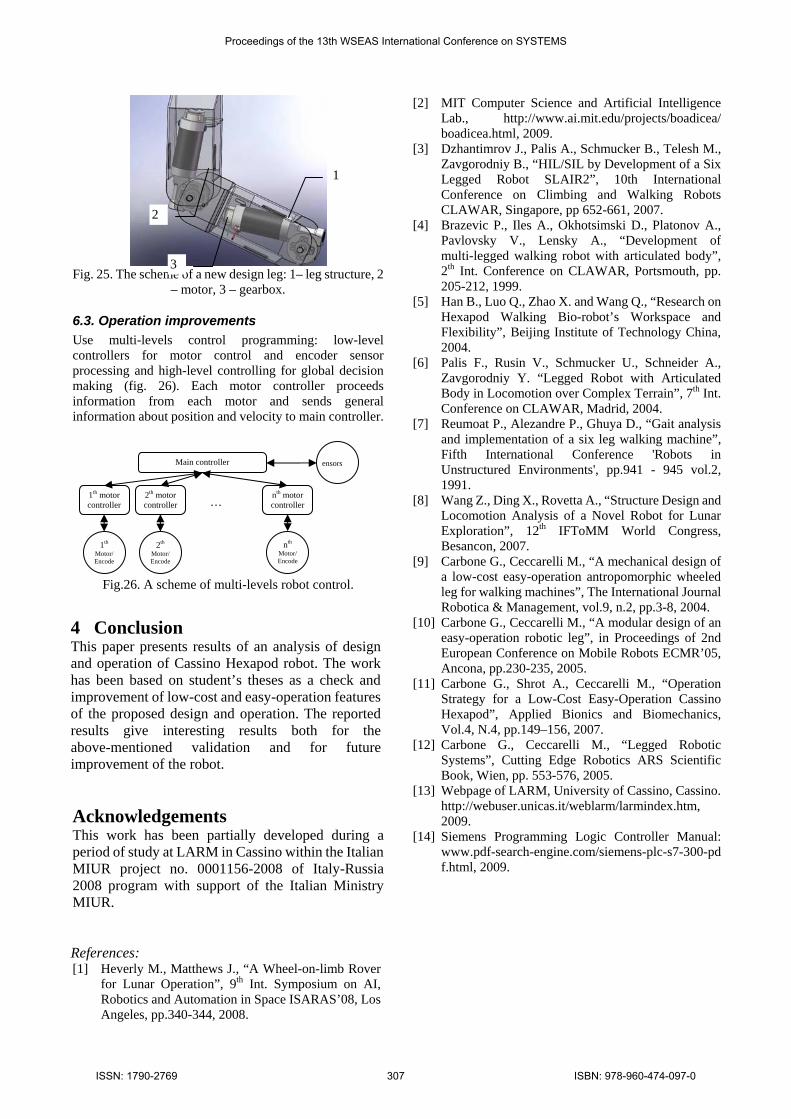
6.2. Mechanical design improvements ch joint to
We also took in account transmefficiency of gear. The maximum torque is about 6 Nmm. The necessary value of torque approximately 70 times less, then we reaches on experiments. It shows that real efficiency of robot is very small and most of torque is going away due friction moments in gearbox and joints.
6 Design and operation improvements Because of the proposed analysis for Cassino Hexapod Robot, the following improvements can be considered for new design and operation features.
Additional sensors could be insinformation about current position of robot parts, about changing environment and others. For example, one could: − install touchdetecting a good contact between wheel and supporting surface. Such kind of sensor can be very useful especially in walking mode of hexapod and in getting over obstacles. − install infrared forward leg for detecting obstacles. Such reflective sensors are very useful and low-cost; they can detect any obstacle at a distance from 50 mm to 2 m, depending on robot task and environment. − use motors in each joint with encvelocity measuring. It will give possibilities to precise control the speed and torque in each motor, so other different algorithms of walking can be applied. Also synchronization problem between each leg can be easily solved.
It is important to use ball bearing in eareduce friction, and even to use another type transmission in each joint with another transmission ratio, (for example only planet gear without belt for simplification and increasing reliability). In fig. 25 a scheme of redesigned leg structure with motor-encoders and worms gear is shown.
Fig.23. test of an operation mode.
Proceedings of the 13th WSEAS International Conference on SYSTEMS
ISSN: 1790-2769 306 ISBN: 978-960-474-097-0
[2] MIT Computer Science and Artificial Intelligence Lab., http://www.ai.mit.edu/projects/boadicea/ boadicea.html, 2009.
[3] Dzhantimrov J., Palis A., Schmucker B., Telesh M., Zavgorodniy B., “HIL/SIL by Development of a Six Legged Robot SLAIR2”, 10th International Conference on Climbing and Walking Robots CLAWAR, Singapore, pp 652-661, 2007.
Fig. 25. The scheme of a new design leg: 1– leg structure, 2 – motor, 3 – gearbox.
6.3. Operation improvements Use multi-levels control programming: low-level controllers for motor control and encoder sensor processing and high-level controlling for global decision making (fig. 26). Each motor controller proceeds information from each motor and sends general information about position and velocity to main controller.
Fig.26. A scheme of multi-levels robot control.
4 Conclusion This paper presents results of an analysis of design and operation of Cassino Hexapod robot. The work has been based on student’s theses as a check and improvement of low-cost and easy-operation features of the proposed design and operation. The reported results give interesting results both for the above-mentioned validation and for future improvement of the robot.
Acknowledgements This work has been partially developed during a period of study at LARM in Cassino within the Italian MIUR project no. 0001156-2008 of Italy-Russia 2008 program with support of the Italian Ministry MIUR. References: [1] Heverly M., Matthews J., “A Wheel-on-limb Rover
for Lunar Operation”, 9th Int. Symposium on AI, Robotics and Automation in Space ISARAS’08, Los Angeles, pp.340-344, 2008.
[4] Brazevic P., Iles A., Okhotsimski D., Platonov A., Pavlovsky V., Lensky A., “Development of multi-legged walking robot with articulated body”, 2th Int. Conference on CLAWAR, Portsmouth, pp. 205-212, 1999.
[5] Han B., Luo Q., Zhao X. and Wang Q., “Research on Hexapod Walking Bio-robot’s Workspace and Flexibility”, Beijing Institute of Technology China, 2004.
[6] Palis F., Rusin V., Schmucker U., Schneider A., Zavgorodniy Y. “Legged Robot with Articulated Body in Locomotion over Complex Terrain”, 7th Int. Conference on CLAWAR, Madrid, 2004.
[7] Reumoat P., Alezandre P., Ghuya D., “Gait analysis and implementation of a six leg walking machine”, Fifth International Conference 'Robots in Unstructured Environments', pp.941 - 945 vol.2, 1991.
[8] Wang Z., Ding X., Rovetta A., “Structure Design and Locomotion Analysis of a Novel Robot for Lunar Exploration”, 12th IFToMM World Congress, Besancon, 2007.
[9] Carbone G., Ceccarelli M., “A mechanical design of a low-cost easy-operation antropomorphic wheeled leg for walking machines”, The International Journal Robotica & Management, vol.9, n.2, pp.3-8, 2004.
[10] Carbone G., Ceccarelli M., “A modular design of an easy-operation robotic leg”, in Proceedings of 2nd European Conference on Mobile Robots ECMR’05, Ancona, pp.230-235, 2005.
[11] Carbone G., Shrot A., Ceccarelli M., “Operation Strategy for a Low-Cost Easy-Operation Cassino Hexapod”, Applied Bionics and Biomechanics, Vol.4, N.4, pp.149–156, 2007.
[12] Carbone G., Ceccarelli M., “Legged Robotic Systems”, Cutting Edge Robotics ARS Scientific Book, Wien, pp. 553-576, 2005.
[13] Webpage of LARM, University of Cassino, Cassino. http://webuser.unicas.it/weblarm/larmindex.htm, 2009.
[14] Siemens Programming Logic Controller Manual: www.pdf-search-engine.com/siemens-plc-s7-300-pdf.html, 2009.
Main controller
1th motor controller
2th motor controller
nth motor controller
1th Motor/Encode
2th Motor/Encode
nth Motor/Encode
ensors
…
1
2
3
Proceedings of the 13th WSEAS International Conference on SYSTEMS
ISSN: 1790-2769 307 ISBN: 978-960-474-097-0