design and simulation of a secured enterprise network for
TRANSCRIPT

Computer Engineering and Intelligent Systems www.iiste.org
ISSN 2222-1719 (Paper) ISSN 2222-2863 (Online) DOI: 10.7176/CEIS
Vol.10, No.5, 2019
26
Design and Simulation of a Secured Enterprise Network for
Faculty of Engineering, Rivers State University
Joseph Diema Enoch1* Sunny Orike2 Christopher. O. Ahiakwo3
Department of Electrical and Computer Engineering
Rivers State University, Port Harcourt, Nigeria
Abstract
Institutions generally seek for a network infrastructure solution that intelligently combines voice and data
networks. To compete globally, It has become necessary for the Faculty of Engineering to build and setup a
secured enterprise network solution to drive the rapid engineering and technological advancement of the
University. The aim of this study is to develop a secured, scalable, available, and manageable enterprise network
for the Faculty of Engineering, Rivers State University, Port Harcourt, Nigeria. In this article the various services
that comprise the enterprise network as a unit have been put together using the Hierarchical Network Model. The
physical and logical network topology was designed for the Faculty of Engineering infrastructures and the results
from the simulation showed that any user who tried to connect to the network and initiated http traffic were
redirected to the authentication server for verification of credentials, before being allowed on the network. The
result also shows that the Cisco Adaptive Security Appliance, the Core Router, the distribution switches and the
integrated service routers were properly configured. The design reduced network device load and the time to
identify network issues to resolve them. The configured network security provided availability, integrity, and
confidentiality. This design also enhanced rapid connectivity, and the inclusion of new devices did not affect the
transfer of packets. Finally, the specifications and commands used in this study is a model that could be modified
and deployed for other Faculties or Universities.
Keywords: Configuration,design, enterprise network, topology, security, Cisco ASA.
DOI: 10.7176/CEIS/10-5-04
Publication date:June 30th 2019
1.0 INTRODUCTION
The Faculty of Engineering is the foremost Faculty of Rivers State University, it is strongly committed to the
vision of a world leading University; known for excellence and creativity, and stand as a beacon for the future.
Its mission is to provide high quality Engineering Education and Research with a strong practical content on a
sound Engineering Science Base and to equip graduates with global engineering best practices. The Faculty of
Engineering is rapidly developing and growing in both education and research, whilst maintaining and enhancing
excellence (Faculty of Engineering RSU, n.d.). To compete globally, the Faculty needs to build and setup a
secured enterprise network solution to drive the rapid engineering and technological advancement of the
University. This solution when fully deployed would showcase the Faculty and enable her standout globally and
further shift the ranking and ratings of the University among the best in the World. The Faculty of Engineering
has eight (8) Departments, namely: (1) Agriculture & Environmental Engineering (2) Chemical/Petrochemical
Engineering (3) Civil Engineering (4) Computer Engineering (5) Electrical Engineering (6) Marine Engineering
(7) Mechanical Engineering and (8) Petroleum Engineering
The deployment of a secure enterprise network is now on high demand by Institutions globally especially in
the developing countries. Secured enterprise network is the protection of the usability and integrity of a group of
local area networks (LANs) interconnected using wide area networks (WANs) technology (Cisco Systems USA,
2018, Cisco Systems USA, 2019). It is the process of securing the connections of computers & devices to
facilitate the accessibility of data within a network of an Institution, Business or organization (Fujisoft, 2019).
There are different kinds of services an enterprise network provides to an Institutions, businesses, or
organisations. In the course of a day, a person might make a phone call, send and receive mails, attend and
participate in a virtual class or board meetings, watch a television show, listen to the radio, look up something on
the Internet, access an application software, send and receive assignments or lecture materials, or even play a
video game with someone in another country. Networks provide the ability to connect people and equipment no
matter where they are in the world. In this research, I have put together the design that comprises a secured
enterprise network for the Faculty of Engineering to enforce network security: confidentiality, authentication and
integrity.
The aim of this study is to design a secured, scalable, available, and manageable enterprise network for the
Faculty of Engineering, Rivers State University, Port Harcourt, Nigeria. The significance of the study is to
minimization cost, forester fast Communication, ease manageability, enhance security, productivity and
performance. The fundamental design goals of this study are to achieve scalability, availability, security and
manageability of the enterprise network for the Faculty of Engineering. Therefore, the scope of this study is to

Computer Engineering and Intelligent Systems www.iiste.org
ISSN 2222-1719 (Paper) ISSN 2222-2863 (Online) DOI: 10.7176/CEIS
Vol.10, No.5, 2019
27
meet the four fundamental design goals, which allows for both flexibility and growth.
2.0 Reviews
2.1 Extent of Past Work
Several studies have been carried out on Enterprise Network. A study carried out by Shiv-Yadav and Ashraf
(2016), concentrated on the Enterprise Network Design and Implementation for Airports. In their study they
looked at three major areas: quality, safety, and security. Utilities for good network security was presented in
their research. The utilities configured to enhance security for the entire network were: proxy server, domain
server, hardware firewalls, Mac address port security, and IP access control list. This was to prevent internal and
external attacks from gaining access to sensitive departments like the service providers and flight management
departments. Cabling system, failover firewalls utility Dynamic Host Configuration Protocol, Pre-boot
Execution Environment, and Domain Name System servers were the technological services used in the airport’s
network. The performance of the network was improved with these technical tools. Two different internet
service vendors services was deployed for the Air Traffic Control System. The role of the internet service
providers was to enable the confirmation of the Air Traffic Control Complex backup operation outside the local
network. The "iSCSI initiators" and "iSCSI target" of Windows server backup was used to accomplish this task.
In addition, the web server was hosted on the local network to offer high level security.
Agbetuyi et al. (2014), Designed and Simulated a Secure and Scalable Enterprise Network. In the research
they put together the various services that comprise the enterprise network as a unit, and have structured out
security policies such as host web authentication and port security, port security in this context working at a
more advanced level. The research work was carried out on Covenant University infrastructure (Senate Building)
and the results showed that any Clients who tried to connect to the network and initiated http traffic were
redirected to the authentication server for verification of credentials, before being allowed on the network and an
email alert was also forwarded to the network administrator. The security services did not impede on network
performance with the implementation of Multi-Layer Switching (MLS).
In this research, Mu’azu and Yahya (2015), focused on the design of an enterprise network by effectively
deploying technologies and protocols as Voice over IP, Access Control Lists, EIGRP routing, Fiber Optics,
VLSM for addressing, Inter VLAN routing, Network Address Translation, use of DHCP and wireless routing.
This research also investigated the major requirement that necessitates an enterprise network for the benefit of
Network Communication Engineers. Seifedine and Wassim (2014), proposed a secure design and
implementation of a network and system in Windows environment using the latest technology. Reviewed the
latest product with an application to an enterprise with worldwide branches are given.
Erik and Tamirat (2013), developed a Local Area Network (LAN) that was secured for a small scale
business. The LAN was able to provide internet services and network resources to employees of the firm and
restricted access was granted to public users. The study also investigated the vulnerability of the small scale
business network. To achieve this goals, the designed network was simulated at the laboratory and the following
configurations were made: Virtual Private Network remote client access, wireless connections, firewalls that
filters outgoing and incoming IP traffic and the layer 3 and 2 security features. The result of the simulation
showed that the network was well secured. It worked for both Internal and remote users connections through
wireless or Internet connection.
Honnia and Johanes (2016), Researched on the development of virtual local area network (VLAN) with a
network simulator called Cisco Packet Tracer. In this case study they implementing the method of LAN
Switching using VLAN to break up broadcast domains into segments, so as to improve network performance. In
the research of Giovannia and Nico (2018), they created a converged network that was geared towards meeting
the technical aspect of a business requirement using the top down network design approach. The process was
accomplished by carrying out design requirement analysis, logical and physical design, and finally, testing the
network. In converged network voice and data traffic perform very well. To accommodate numerous type of
traffic, the quality of service was also considered to optimize the network design. The result of the experiment
and simulation confirmed that the proposed design met the requirement of quality of service for a converged
network, It also showed that it performed better than the existing network design.
Mehzabul (2015), Designed an Enterprise Network Infrastructure of a City. In the study Cisco packet tracer
was used for the design and simulation of a city enterprise network by considering enterprise edge network. The
network was design to include three areas in Dhaka, Banani Branch, Motijheel Branch, and Bangladesh: Data
center. Garima, et al. (2015), focus on mesh, star, and bus topologies to study various behaviours of the
topologies design, and configuration of IP address on network devices and how packets are sent and received in
a single network using Cisco packet tracer network simulator.
Nathaniel, et al. (2017) Designed and Simulated a Local Area Network Using Cisco Packet tracer. The
research work described how Cisco Packet tracer was used to simulate the LAN model for the College of
Engineering in the University of Agriculture, Makurdi, Nigeria. The study offered detailed explanation on the

Computer Engineering and Intelligent Systems www.iiste.org
ISSN 2222-1719 (Paper) ISSN 2222-2863 (Online) DOI: 10.7176/CEIS
Vol.10, No.5, 2019
28
use of Virtual Local Area Networks to segment the network for each departments in the college of engineering.
It also analyze the transfer of packets on a network..
Chunlin, et al. (2017), explore genetic algorithm in other to use it for network topology design from
hierarchical network model. It was made up of lower physical topology and upper logical topology. The self-
similar traffic was modeled using the ON/OFF model and the self-similar traffic information on the network was
described by the logical topology. The network connection of devices and links were represented in the lower
physical topology. This study proposed a genetic algorithm technique for developing a novel network topology
design in order to obtain a network with minimum cost and delay under certain reliability. In conclusion a
practical test was carried out to verify the accuracy and the effectiveness of the network topology design. The
result of the test showed that the techniques was better than the referenced methods.
2.2 Identified Knowledge Gap
The Several studies carried out on the design and simulation of an Enterprise Network, did not handle the
physical and logical design of an enterprise network for the proposed case study but demonstrated the
generalized design implementation with a network simulator. None of the researchers included the use of Cisco
Adaptive Security Appliance (ASA) device, which is a dedicated network security hardware that prevents both
internal and external attacks on the network. Furthermore, none of the researchers developed a customized
encryption and decryption solution to secure the database of the proposed case study. Finally, it was observed
that none of the researchers included the bill of engineering measurement and evaluation of the proposed
designed case study to enable IT/Network Engineers deploy the proposed design.
2.3 Current Work and Expected Outcome
This research is to design and simulate a secured enterprise network for Faculty of Engineering Rivers State
University, Port Harcourt, Nigeria. In addition, this research work would be geared towards achieving the
identified knowledge gap as stated above. At the accomplishment of this research work, we would have
developed a solution that would enable Network/Communication Engineers deploy the design of a secured,
scalable, available, and manageable enterprise network for the Faculty of Engineering, Rivers State University,
Port Harcourt, Nigeria and also serve as a prototype for other Faculties.
3.0 MATERIALS AND METHOD
3.1 Materials
The materials that were used for this study are: Cisco Adaptive Security Appliance (ASA) device, Cisco Packet
Tracer 7.2, Java Script, php program, Linksys Smart Wi-Fi Wireless Router, Cisco Routers, Cisco and Linksys
Switches, Linksys Wireless USB Card, 4500 Fingerprint Scanner, Hotspot Manager Software, Microsoft Server
2019 Standard and Datacenter Edition, Microsoft Exchange Server 2016, HP Desktop Workstations, HP Core i3,
i5 & i7 Laptops, HP Servers and Rack, Uninterrupted Power Supply (UPS), 5KVA Inverter + 4 Batteries, Unifi
Pro Wireless Access Point, Network Cable (Dt Cat 6 S/FTP), RJ-45, AVS Voltage Guide 30AMP, Cisco Small
Business Switch, Nails, Trunks, Pipe & other Accessories, APC Surge Protector, Enterprise Internet Security and
Firewall, Radio APC Surge Protector, MS Internet UBIQUITI-UAP OUTDOOR plus Radio, 8 Port Unifi POE
Switch, Cable Ties, 25mm Earth Cable (Pure Copper), Copper Arrestor (Long), Earth Clamp (Big), Earth Rod
(6ft) Force, Copper Nail, Copper Lug, IDS Salt, Charcoal Dakin, and Copper Mart (Big).
3.2 Methodology
The method used for the design of the secured enterprise network is the top down network design approach. This
method enhances optimization of network resources and proffer better solution than bottom-up network design
approach. This techniques comprises of four stages, i.e. (i) Identifying Design Requirement and Goals, (ii)
Logical Network Design, (iii) Physical Network Design, (iv) Testing, Optimizing, and Documenting Network
Design.
3.2.1. Identifying Design Requirement and Goals
This section of the study was achieved by obtaining relevant data from users. The usersare made up of students,
lecturers and none teaching staff in the Institution. The information about the size of classes, Laboratories, Office
Complexes, and the number of students and staff for each Department in the Faculty were obtained along with
future needs of the Faculty. To aid the design of the logical and physical topology of the Institution's Enterprise
Network.
Total Number of Users for the case study = No of staff + Students= 7,674
Network design plan is for 32,736 users, which can be scaled to about 65,000 users
3.2.2. Logical Network Design
This section is concerned with the development of the proposed logical network design. The procedures for
designing logical network involves the design of network topology, routing protocol selection, and redundancy

Computer Engineering and Intelligent Systems www.iiste.org
ISSN 2222-1719 (Paper) ISSN 2222-2863 (Online) DOI: 10.7176/CEIS
Vol.10, No.5, 2019
29
technique for increasing availability. The hierarchical network design approach was adoptedowing to itsbenefits
over flat network designtechnique. There are three basic layers that characterized the hierarchical design model:
Core layer, which links distribution layer devices, Distribution layer, which Interconnects the smaller local
networks, and Access layer, which provides connectivity for network hosts and end devices.
Figure 3.1: Diagram of Hierarchical Design Model source: Cisco Systems USA (n.d.)
3.3. Physical Network Design
The physical network design stage involves choosing an appropriate LAN and WAN technologies to deploy
anInstitution Enterprise Network. The selections are made based on cabling, physical and data link layer
protocols, and internetworking devices (such as wireless access points, routers, andswitches).
3.4. Network Design Considerations
The design consideration for the core layer includes avoidanceto unnecessary delays in network traffic which is a
top priority for the network design, andfault tolerance, because all users in the network can be affected by a
failure. The distribution layer design consideration involves routing, filtering, and interconnection between the
core layer and the access layer. The access layer provides the platform for user access to network resources.
Since the access layer is bound for other segments within the network, it would facilitate the traffic generated.
The design consideration for the wireless network was basedon the physical coverage areas of the network, and
to determine the optimum locations for mounting wireless access points. The number of users within each
coverage area, was used to determine the types of antennas, access point hardware, and the required wireless
feature sets.
Figure 3.2: Physical Network Topology for the Faculty of Engineering Infrastructure

Computer Engineering and Intelligent Systems www.iiste.org
ISSN 2222-1719 (Paper) ISSN 2222-2863 (Online) DOI: 10.7176/CEIS
Vol.10, No.5, 2019
30
Figure 3.3: Logical Network Topology for the Faculty of Engineering Infrastructure
3.5 Network Architecture
The core router in figure 2 had one of its interface connected to the Internet through the Cisco Adaptive security
appliance and the other to the DMZ (De-Militrialized Zone). The DMZ had a switch which hosted serversnamely;
FTP, Web, Email and application servers. The distribution layer had three switches connecting the virtual local
area network (VLAN) of the following units of the Institution; Laboratories, Lecture Theatres, Conference Room,
Library, Departmental Offices, Staff Offices, IT Unit and Administrative Unit. The listed units are locations with
different sub-networks that made up the access layer.
3.6 Network Addressing and Subnetting
In this section of the design process, the class B private Internet Protocol (IP) Address was specified for each
devices on the IP network. This would enable the transmission of packets to the exact location of a user device
on the network. No matter the type of LAN a user is connected to, the IP addressenable hosts from a network
could interact with hosts on another network (Nathaniel et al., 2017). Furthermore, for proper management of
traffic, speed and availability of the network, the IP addresses were subnetted. The practice of taking bits from
the host part of an IP address for the purpose of reducing the size of a network is called subnetting (Nathaniel et
al., 2017). Host fields of a subnet in a network are formed after subnetting. Two IP addresses areset asidefor the
subnet and the other for the broadcast address in the subnet. We can implement Subnetting in three fundamental
methods, the first is done considering the number of small networks you intend to built from a particular group
of IP address; the second method is could be obtained from the number of host systems you wish to join a
network and thirdly, by reverse engineering that is a method in which an IP address block and a subnet mask is
known and the number of sub-networks and hosts per each subnet are obtainable (Nathaniel et al., 2017). The
internal network address selected is 172.16.0.0 with a mask of 255.255.0.0.
There are some equation that can be used to obtain the required information for subnetting as follows:
Number of subnet = (1)
Number of host per subnet = (2)
Block size = Increment = 256 - subnet mask (3)
Where:
x =Number bits on the network part or masked bits and
y = The number bits on the host part or unmasked bits
Therefore, in this study at least 2024 hosts per subnet is required
From equation (2)
Number of host per subnet =
2044 =
2046 =

Computer Engineering and Intelligent Systems www.iiste.org
ISSN 2222-1719 (Paper) ISSN 2222-2863 (Online) DOI: 10.7176/CEIS
Vol.10, No.5, 2019
31
y = log2 (2046) = = 10.998 ≈ 11
Therefore
The number of masked bits = x = 5;
Hence, from the calculation the new subnet mask in binary
and in decimal
The table below shows the subnets obtained from the computation.
Table 3.1: The obtained Subnets
S/N Network Location Network
Address
First valid
Host
Last Valid
Host Broadcast
1 Faculty Building 172.16.0.0 172.16.0.1 172.16.7.254 172.16.7.255
2 Agricultural Engineering
Laboratory 172.16.8.0 172.16.8.1 172.16.15.254 172.16.15.255
3 Chemical/ Petrochemical
Engineering Laboratory 172.16.16.0 172.16.16.1 172.16.23.254 172.16.23.255
4 Civil Engineering Laboratory 172.16.24.0 172.16.24.1 172.16.31.254 172.16.31.255
5 Computer Engineering Building/
Laboratory 172.16.32.0 172.16.32.1 172.16.39.254 172.16.39.255
6 Electrical Engineering
Laboratory 172.16.40.0 172.16.40.1 172.16.47.254 172.16.47.255
7 Marine Engineering Building 172.16.48.0 172.16.48.1 172.16.55.254 172.16.55.255
8 Mechanical Engineering
Laboratory 172.16.56.0 172.16.56.1 172.16.63.254 172.16.63.255
9 Petroleum Engineering Building 172.16.64.0 172.16.64.1 172.16.71.254 172.16.71.255
10 NEH Building 172.16.72.0 172.16.72.1 172.16.79.254 172.16.79.255
11 Centre of Excellence Marine &
Offshore Engineering 172.16.80.0 172.16.80.1 172.16.87.254 172.16.87.255
12 ChemPet PTDF Building 172.16.88.0 172.16.88.1 172.16.95.254 172.16.95.255
13 Nkpolu Bank Building 172.16.96.0 172.16.96.1 172.16.103.254 172.16.103.255
14 EDH, EDR & MDH Building 172.16.104.0 172.16.104.1 172.16.111.254 172.16.111.255
15 LT Building 172.16.112.0 172.16.112.1 172.16.119.254 172.16.119.255
16 Amphitheatre Building 172.16.120.0 172.16.120.1 172.16.127.254 172.16.127.255
Table 3.1 showed the range of network host addresses that would be used to allocate IP addresses on the
LAN for each building within the Faculty of Engineering. It also showed the network and broadcast addresses
each LAN devices or users will be operating on at any of the buildings within the Faculty of Engineering.
3.7 Switch Configurations
The code configured on the switches were, creation of trunk port for the Router, creation of access ports,
configuration of default-gateway, creation of VLANs and assignment of switch ports to the VLANs.
3.7.1 Trunk-to-Router
The following commands were used to configure a trunk port on the switch and all other access ports, the switch
command Line interface (CLI)was used to run the commands.
EngrgSW(config)# int fastethernet 0/2
EngrgSW(config-if)# switchport mode trunk
EngrgSW(config-if)# spanning-tree portfast trunk
EngrgSW(config-if)# interface range fa0/3 – 23
EngrgSW(config-if-range)# switchport mode access
EngrgSW(config-if-range)# end
3.7.2 Creating Virtual Local Area Network (VLANs)
There are about sixteen buildings within the Faculty of Engineering infrastructure at Rivers State University,
Port Harcourt, Nigeria, which included the Faculty Building, the departmental laboratories, Lecture halls etc.
each of the buildings will be connected on a separate VLAN, In all sixteen (16) VLANs were created. The
command used to create the VLAN on the switch, is as follows:
EngrgSW(config)#vlan [id].
The following commands were used to create the VLAN for the Faculty of Engineering (FE) main building and
to assign an easy identifiable name:

Computer Engineering and Intelligent Systems www.iiste.org
ISSN 2222-1719 (Paper) ISSN 2222-2863 (Online) DOI: 10.7176/CEIS
Vol.10, No.5, 2019
32
EngrgSW(config)#vlan 10
EngrgSW(config-vlan)#name FE
The code above was used to configure the VLAN IDs and Names for other VLANs.
3.7.3 Assigning Switch Ports to VLANs
To make the switch have different broadcast domain, we assigned each created VLAN to a switch port. The
basic codes used to assign a switch ports to a VLAN is as follows:
Switch (config)#interface [interface type] [interface
identifier]
Switch (config-if)#switchport access vlan [vlan id]
The function of the first code is to choose the switch port you want to assign the VLAN to. The switch “interface
type” could be fastethernet or gigabitethernet port, and the “interface identifier” is in the form of 0/1, 0/2, 0/3,
0/4,…0/n that is from the first switch port, up to the last switch port. The function of the next code is to assign a
“vlan id” the port should be part of. The configuration command used to assign the Faculty of Engineering
VLAN, is as shown:
EngrgSW(config)#interface fastethernet0/3
EngrgSW(config-if)#switchport access vlan 10
EngrgSW(config-if)#interface fastethernet0/4
EngrgSW(config-if)#switchport access vlan 10
To achieve redundancy parts, two ports were assigned the same VLAN ID.
3.7.4 Configuring Default-Gateway
The basic command used for configuring the default gateway for each VLANs is shown below. The default
gateway is configured to enables packets destined for outside network.
Switch(config)#ip default-gateway [ip address].
In the code above the “ip address” is for the interface linking the VLAN to the Router. Therefore, the commands
configured for the gateways is as follows:
The Faculty of Engineering: VLAN 10
FE(config)#ip default-gateway 172.16.0.1
The Agric. and Env. Engineering Lab: VLAN 20
AGRICSW(config)#ip default-gateway 172.16.8.1
The Chemical/Petrochemical Engrg. Lab:VLAN 30
CHEMSW(config)#ip default-gateway 172.16.16.1
The Civil Engineering Lab: VLAN 40
CIVSW(config)#ip default-gateway 172.16.24.1
The Computer Engineering Building/Lab: VLAN 50
CENSW(config)#ip default-gateway 172.16.32.1
The Electrical Engineering Lab: VLAN 60
EEESW(config)#ip default-gateway 172.16.40.1
The Marine Engineering Building/Lab: VLAN 70
MARSW(config)#ip default-gateway 172.16.48.1
The Mechanical Engineering Lab: VLAN 80
MECSW(config)#ip default-gateway 172.16.56.1
The Petroleum Engineering Building: VLAN 90
PETSW(config)#ip default-gateway 172.16.64.1
The New Engineering Hall Building: VLAN 100
NEHSW(config)#ip default-gateway 172.16.72.1
The CoE Marine and Offshore Engrg: VLAN 110
COESW(config)#ip default-gateway 172.16.80.1
The PTDF Buildingof Chem/Pet Engrg.:VLAN 120
CPTDFSW(config)#ip default-gateway 172.16.88.1
The RSU Nkpolu Bank Building: VLAN 130
RSUNBSW(config)#ip default-gateway 172.16.96.1
The Faculty Engineering Drawing Hall: VLAN 140
EDHSW(config)#ip default-gateway 172.16.104.1
The Lecture Theatre(LT1-3) Building: VLAN 150
LTSW(config)#ip default-gateway 172.16.112.1
The Amphitheatre: VLAN 160
AMPHSW(config)#ip default-gateway 172.16.120.1

Computer Engineering and Intelligent Systems www.iiste.org
ISSN 2222-1719 (Paper) ISSN 2222-2863 (Online) DOI: 10.7176/CEIS
Vol.10, No.5, 2019
33
3.8 Router Configurations
The most potent network device is the router and to achieve this research goals the following configurations
were made, DHCP, inter VLAN routing, DHCP relay, Network Address Translation (NAT), coding sub-
interfaces for all VLANs on the two main Switches.
3.8.1 Create Sub-Interfaces for Each VLAN
Sub-interfaces were configured on the router interface linking the trunk port on the switch because it is more
costly to purchase a router with large number of interfaces. The sub-interfaces will enable data from all VLANs
to get to the router. The basic command used to create the sub-interfaces is as shown below:
Core_router(config)#interface [interface type] [interface identifier break]
The parameter “interface type” is either a fastethernet or a gigabitethernet port and the parameter “interface
identifier break” begins the setup of the sub-interfaces for example 0 / 1.1 to configure the first sub-interface.
The router sub-interfaces, DHCP relay, NAT and inter-VLAN routing was configured using the commands
below.
Core_router#configure terminal
Core_router(config)# interface gig0/1
Core_router(config-if)#no ip address
Core_router(config-if)#duplex auto
Core_router(config-if)#speed auto
Core_router(config-if)#interface gig0/1.1
Core_router(config-subif)#description VLAN10_interface
Core_router(config-subif)#encapsulation dot1q 10
Core_router(config-subif)#ip address 172.16.0.1 255.255.248.0
Core_router(config-subif)#ipnat inside
Core_router(config-subif)#ip helper-address 172.16.4.3
Core_router(config-subif)#end
The ID and IP addresses of the other VLANs were configured using the same command above.
3.8.2 Configuring the Cisco Adaptive Security Appliance (ASA)
The following commands were used to configure the Cisco ASA, the ASA command Line interface (CLI) was
used to run the commands:
engrgasa(config)# interface GigabitEthernet0/0
engrgasa(config-if)# speed 100
engrgasa(config-if)# duplex full
engrgasa(config-if)# no nameif
engrgasa(config-if)# no security-level
engrgasa(config-if)# no ip address
engrgasa(config-if)# interface GigabitEthernet0/0.5
engrgasa(config-subif)# description OUTSIDE1
engrgasa(config-subif)# vlan 5
engrgasa(config-subif)# nameif OUT1
engrgasa(config-subif)# security-level 0
engrgasa(config-subif)# ip address 192.168.8.1 255.255.255.0
engrgasa(config-if)# interface GigabitEthernet0/1
engrgasa(config-subif)# speed 100
engrgasa(config-subif)# duplex full
engrgasa(config-subif)# no nameif
engrgasa(config-subif)# no security-level
engrgasa(config-subif)# no ip address
engrgasa(config-if)# interface GigabitEthernet0/1.10
engrgasa(config-subif)# description INSIDE1
engrgasa(config-subif)# vlan 10
engrgasa(config-subif)# nameif INSIDE1
engrgasa(config-subif)# security-level 90
engrgasa(config-subif)# ip address 172.16.0.1 255.255.248.0
The commands above was repeated to configure the other VLANs.
3.8.3 Wireless Access Point (WAP) Configurations
The WAP was configured using the graphical user interface (GUI) in Packet Tracer. From the GUI the config tab
was selected to access the configuration options on the WAP. To select the bandwidth of the Ethernet connection
of the WAP, on the interface area select port 0 and then set the duplex (full duplex or half duplex). To setup the
SSID of the WAP, on the interface area select port 1, select authentication type e.g. WPA2-PSK among others

Computer Engineering and Intelligent Systems www.iiste.org
ISSN 2222-1719 (Paper) ISSN 2222-2863 (Online) DOI: 10.7176/CEIS
Vol.10, No.5, 2019
34
(none, WEP, WPA-PSK, WPA2-PSK) and input the pass phrase for the chosen authentication to get connected
on the network.
3.9 Server Configuration
The Network deployment for the Faculty needs the services of a Remote Desktop service, DNS, DHCP, SMTP,
HTTP and AAA servers. The details setup information is as follows:
3.9.1 Dynamic Host Configuration Protocol (DHCP) Server Setup
The graphical user interface of the first server was used to configure the DHCP server by selecting the DHCP
service from the services tab, and thereafter turn on the DHCP service to provide the platform to configure the
address pools of the DHCP server for each VLANs on the network. The parameters used to setup the address
pools on the server is as follows:
VLAN 10 Configuration
Parameters:
Poolname: VLAN10
Default gateway: 172.16.0.1
DNS server: 172.16.4.3
Start IP address: 172.16.0.16
Subnet mask: 255.255. 248.0
Total users: 2046
VLAN 20 Configuration
Parameters:
Poolname: VLAN20
Default gateway: 172.16.8.1
DNS server: 172.16.4.3
Start IP address: 172.16.8.5
Subnet mask: 255.255.248.0
Total users: 2046
VLAN 30 Configuration
Parameters:
Poolname: VLAN30
Default gateway: 172.16.16.1
DNS server: 172.16.4.3
Start IP address: 172.16.16.5
Subnet mask: 255.255. 248.0
Total users: 2046
The configuration parameters above was repeated for the other VLANs (VLAN40 - VLAN160)
The add button was used to include the inputted parameter of the address pools for each VLANs on the
DHCP server. Not all the IP addresses are used for the DHCP address pools. The reason is to reserve them for
some network equipment that may require manual assignment of static IP address and also for the expansion of
the network. In this research VLAN 10 is the network for the administrative centre of the institution. In this
VLAN more IP address were reserved to enable the network administrator manually assign static IP addresses to
network equipments at the centre.
Other servers configured include: Domain Name Server (DNS), Hyper Text Transfer Protocol (HTTP)
Server, Email Server, Authentication, Authorization, and Accounting (AAA) Server by using the graphical user
interface (GUI) of the servers to configure it. This was achieved by clicking the services tab, and choosing the
required service.
Security configurations on the network include coding passwords on the Routers and Switches, Setting up
Console Port and Telnet Connection Passwords, Setting up Secure Shell (SSH), Setting up an AAA Model on
the Router, Access Control List Configuration
4.0 RESULTS AND DISCUSSION
4.1 The Simulation of the Enterprise Network
The simulation screen capture shown in figure 4.1 is a prototype design of a secured enterprise network. It shows
that the Cisco Adaptive Security Appliance, the Core Router, the two distribution switches and the integrated
service routers were properly configured to provide network coverage to the entire Faculty Infrastructure. The
green circular lights indicates network connectivity between the Servers, router, switches, internet and other
devices. Furthermore, the integrated service routers/access points creates a point of presence (POP) network
coverage within each buildings in the Faculty that enabled wireless connectivity and communication among PCs,
Laptops, PDA’s and other devices with WiFi enabled technologies.

Computer Engineering and Intelligent Systems www.iiste.org
ISSN 2222-1719 (Paper) ISSN 2222-2863 (Online) DOI: 10.7176/CEIS
Vol.10, No.5, 2019
35
Figure 4.1: Prototype Design of the Faculty Enterprise Network
4.2 Verifying Router Configurations
The result of the “show ip route” and “show ip int brief” command is as shown in Figure 4.2. the result
indicates that the routing protocol and router interface configuration was functioning as expected.
Figure 4.2 Configured Interface of Core Router
4.3 Verifying the Virtual Local Area Network (VLAN)
The result of the “show vlan brief” command is captured in Figure 4.3 which indicates that the VLANs are
active, the ID and ports corresponding to all VLANs assigned to each building in the Faculty are active and
working as expected.

Computer Engineering and Intelligent Systems www.iiste.org
ISSN 2222-1719 (Paper) ISSN 2222-2863 (Online) DOI: 10.7176/CEIS
Vol.10, No.5, 2019
36
Figure 4.3: VLANs created on the Switch
4.4 Verifying User Connections at Various Locations in the Faculty
The results of the user devices that received an IP address after the connection to the network are shown in
Figure 4.4 with the VLAN they are connected to.
Faculty Building Subnet
(172.16.0.0/21)
Agric.&Env. Subnet
(172.16.8.0/21)
Chem/Pet. Lab Subnet
(172.16.16.0/21)
Civil Lab Subnet (172.16.24.0/21)
Computer Subnet (172.16.32.0/21)
Electrical Lab Subnet
(172.16.40.0/21)

Computer Engineering and Intelligent Systems www.iiste.org
ISSN 2222-1719 (Paper) ISSN 2222-2863 (Online) DOI: 10.7176/CEIS
Vol.10, No.5, 2019
37
Marine Subnet (172.16.48.0/21)
Mechanical Subnet
(172.16.56.0/21)
Petroleum Subnet (172.16.64.0/21)
NEH Subnet (172.16.72.0/21)
CoE Marine Subnet
(172.16.80.0/21)
Chem PTDF Subnet
(172.16.88.0/21)
Amphitheatre Subnet
(172.16.120.0/21)
EDH Subnet (172.16.104.0/21)
LT Subnet (172.16.112.0/21)
Figure 4.4: User Devices obtaining IP address from DHCP Server
From figure 4.5 we were able to show that each user connected to the network was able to dynamically
obtain IP address according to the VLAN the user device was connected to by the DHCP Server.
4.5 Network Connectivity Test
The ping command was used for testing the communication and connectivity of the enterprise network, with the
IP address of the user or the domain name. About sixteen VLANs were configured on the network and four
server computers. A ping command was executed to ascertain the connectivity of devices on the VLANs. Figure
4.5 shows the results obtained from the test.

Computer Engineering and Intelligent Systems www.iiste.org
ISSN 2222-1719 (Paper) ISSN 2222-2863 (Online) DOI: 10.7176/CEIS
Vol.10, No.5, 2019
38
Test from Faculty IT Unit to
Gateway Server
Test from Faculty IT Unit to Mail
Server
Test from Faculty IT Unit to FTP
server
Test from Faculty IT Unit to App.
Server Test from Faculty IT Unit to user
at Faculty Office Complex
Test from Faculty IT Unit to user
at Amphitheatre
Fig. 4.5 Network Connectivity Test
From figure 4.5, it was evident that the network was well configured and it is performing optimally as
expected. Hence users on the network at any location within the coverage area could access the resources on the
Faculty enterprise network.
The ping command was also used to test and confirm if the DNS configuration was working as expected,
the command line interface was used to ping the domain name engfaculty.com. The result obtained showed that
the domain name is translated to a valid IP address which ascertain the workability or correctness of the DNS
setup. The result of the test is shown in Figure 4.6.
Figure 4.6 Connectivity Test on the DNS Server
The result obtained in Figure 4.6, clearly showed that the domain name engfaculty.com was translated to
the address of the DNS server IP address 172.16.4.3.
4.6 Verifying the Dynamic Host Configuration Protocol (DHCP)
The result of the DHCP server is shown in Figure 4.7 which displays the DHCP server IP address groups for all
VLANs. A test for the dynamic address assignment was also conducted. A user when connected to the network
automatically obtained an IP address from the address pool the user device is connected to by the DHCP server.
Computer Engineering and Intelligent Systems www.iiste.org
ISSN 2222-1719 (Paper) ISSN 2222-2863 (Online) DOI: 10.7176/CEIS
Vol.10, No.5, 2019
39
Figure 4.7: DHCP Server Pools
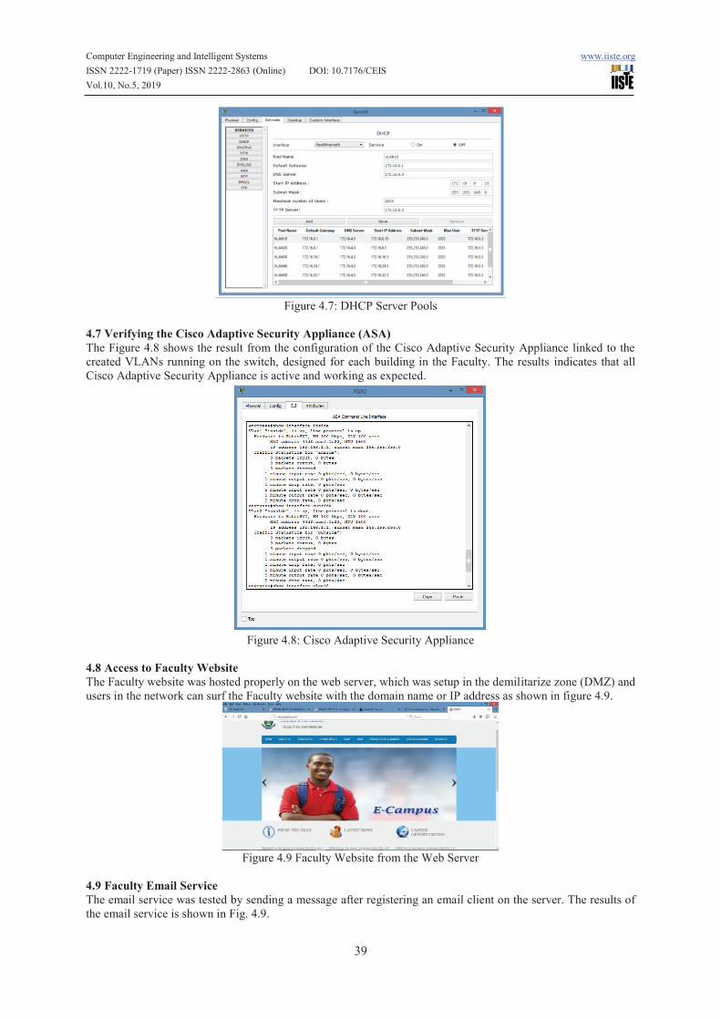
4.7 Verifying the Cisco Adaptive Security Appliance (ASA)
The Figure 4.8 shows the result from the configuration of the Cisco Adaptive Security Appliance linked to the
created VLANs running on the switch, designed for each building in the Faculty. The results indicates that all
Cisco Adaptive Security Appliance is active and working as expected.
Figure 4.8: Cisco Adaptive Security Appliance
4.8 Access to Faculty Website
The Faculty website was hosted properly on the web server, which was setup in the demilitarize zone (DMZ) and
users in the network can surf the Faculty website with the domain name or IP address as shown in figure 4.9.
Figure 4.9 Faculty Website from the Web Server
4.9 Faculty Email Service
The email service was tested by sending a message after registering an email client on the server. The results of
the email service is shown in Fig. 4.9.

Computer Engineering and Intelligent Systems www.iiste.org
ISSN 2222-1719 (Paper) ISSN 2222-2863 (Online) DOI: 10.7176/CEIS
Vol.10, No.5, 2019
40
Figure 4.10 Email Message View
The results from the email client, shows that the mail server was configured correctly on the network and it
is functioning very well.
4.10 Network Deployment Bill of Engineering Measurement and Evaluation (BEME)
The deployment of the secured enterprise network will require buying the network equipment and other
computing resources. A detail bill of engineering measurement and evaluation for the deployment of the Faculty
Enterprise Network is as stated below:
Table 4.1 Bill of Engineering Measurement and Evaluation (BEME) Summaries
Source: Survey Data February, 2019
S/N Description Amount
1 4 HP Servers and Rack 5,040,000.00
2 30 Uninterrupted Power Supply (UPS), 5kVA Inverter + 4 Batteries 3,180,000.00
3 Backup Internet Solution /Subscription 297,600.00
4 Internet and LAN/WLAN Deployment Equipment 10,543,500.00
5 Standard Earthen Reinforcement 354,200.00
Total 19,415,300.00
5.0 CONCLUSION
In this study, the physical and logical network topology was successfully developed from the surveyed data
obtained at the Faculty of Engineering, Rivers State University. A good techniques for designing a secure
enterprise networks for Faculty of Engineering was developed by ensuring internal and external protection using
the Cisco Adaptive Security Appliance.
The method not only stress the significance of using institutional prerequisites and goals in developing a
secure network yet in addition provides built-in mechanisms to capture security needs and use them seamlessly
throughout the steps of analyzing and designing secure network architecture. In this research, an Enterprise
Network for both guided and unguided media was developed by setting up the followings: DHCP, DNS, Email,
Web, FTP, VLANs. With the aid of a router and switches, VLANs were created and packets could be routed
from one device to another.
Furthermore, the network was designed to reduce network device load by limiting number of device
interconnection and broadcast domain. It further reduced cost by using appropriate specification per layered
device. Finally, it reduce time to identify problem and proffer solution. The computerization of the Institution,
would provided competitive advantage for staff in the Faculty of Engineering, since it creates an extremely
dynamic and flexible work environment, allowing lecturers be in a permanent contact and interaction with their
students, which is the fundamental basis for e-learning. Finally, the specifications and commands used in this
study is a model that could be modified and deployed for other Faculties or Universities.
5.1 Recommendations for Future Work
(a) The Addition of Biometric and CCTV technologies for advance access control and security to provide robust
end-to-end security is recommended for future work on this study.
(b) The use of IPv6 addressing is highly recommended. This will enable all users or devices on the network to
be assigned a unique IP address for easy identification and authentication.
(c) Increase the target storage capacity of the Institutions storage backup by acquiring additional high capacity
storage devices and a cloud storage solution for users on the network.

Computer Engineering and Intelligent Systems www.iiste.org
ISSN 2222-1719 (Paper) ISSN 2222-2863 (Online) DOI: 10.7176/CEIS
Vol.10, No.5, 2019
41
REFERENCES
Agbetuyi, A. F., Akinpelumi, O. B., & Adewale, A. A. (2014). Design and Simulation of a Secure and Scalable
Enterprise Network. Published at Accepted International Conference Paper: 9th International Workshop on
Security and High Performance Computing Systems. Retrieved from
http://m.covenantuniversity.edu.ng/Profiles/ Adewale-Adeyinka-Ajao/Design-and-Simulation-of-a-Secure-
and-Scalable-Enterprise-Network. November 3rd, 2018.
Chunlin, W., Ning, H., Shuo Z., Yue, Z., & Weiqiang, W. (2017). A hierarchical network model for network
topology design using genetic algorithm. MATEC Web of Conferences 119, 01008 (2017). DOI:
10.1051/matecconf/201711901008
Cisco Systems USA (2018). Enterprise Network Design, Retrieved from
http://www.cisco.com/warp/public/cc/so/neso/meso/uentd_pg.pdf. December 13th, 2018.
Cisco Systems USA (2019). What is Network Security. Retrieved from https://www.cisco.com/c/en/
us/products/security/what-is-network-security.html. January11th, 2019.
Cisco Systems USA (n.d.). Cisco Certified Network Associate (CCNA-RS) Routing and Switching. Module 3
Training Manual on Network Protocols and Communications, (pp. 1-45).
Erik, P., & Tamirat, A. (2013, May 6), Design and Simulation of Local Area Network Using Cisco Packet Tracer.
Bachelor of Engineering Degree Project. Submitted to the Faculty of Information Technology, Helsinki
Metropolia University of Applied Sciences, Finland. Retrieved from http://www.theijes.com/papers/vol6-
issue10/Version2/ I0610026377.pdf. January 15th, 2019.
Faculty of Engineering RSU (n.d.). About the Faculty of Engineering, Rivers State University, Nieria. Retrieved
from http://engineering.ust.edu.ng/index.php/dean. December 20th, 2018.
Fujisoft (2019). What Is Enterprise Networking And Why Is It Crucial For Organizations. Retrieved from
http://fujisoft.com/what-is-enterprise-networking-and-why-is-it-crucial-for-organizations/ January 15th,
2019.
Garima, J., Nasreen, N., Nisha, K., & Sourabh, S. (2015). Designing & Simulation of Topology Network using
Packet Tracer. International Research Journal of Engineering and Technology (IRJET), 2(2), 793-795.
Retrieved from https://www.irjet.net/archives/V2/i2/Irjet-v2i2144.pdf. January, 15th 2019.
Giovannia, G., & Nico, S. (2018). Design and Evaluation of Enterprise Network with Converged Services. In the
Proceeding of 3rd International Conference on Computer Science and Computational Intelligence 2018,
(pp. 526–533). retrieved from https://ac.els-cdn.com/S1877050918314959/1-s2.0-S1877050918314959-
main.pdf?_ tid=ae40d0c7-26a7-4b8d-aa20-30c57d3391d5&acdnat=1547811076_
a2224a4eba09463ae338f58d1c55fde5. January, 18th 2019.
Honnia, H., & Johanes, F. A. (2016). Design and Simulation VLAN Using Cisco Packet Tracer: A Case Study.
In Proceeding of International Seminar on Mathematics, Science, and Computer Education, 15 October (pp.
66-72), Retrieved from https://www.researchgate.net/publication/324311605_Design_and_ Simulation_
VLAN_Using_Cisco_Packet_Tracer_A_Case_Study. January, 5th 2019.
Mehzabul, H. N. (2015). Design of an Enterprise Network Infrastructure of a City. International Journal of
Advanced Research in Computer and Communication Engineering 4(9), 528-531. DOI
10.17148/IJARCCE.2015.49117. Retrieved from https://ijarcce.com/wp-content/uploads/
2015/10/IJARCCE-117.pdf. January, 18th 2019.
Mu’azu, M. B., & Yahya, F. (2015). “DESIGN AND SIMULATION OF AN ENTERPRISE NETWORK
USING PACKET TRACER: A Case Study of a Model Secondary School” (Degree Project, Ahmadu Bello
University (ABU), Zaria, Nigeria). Retrieved from
https://www.academia.edu/32444198/DESIGN_AND_SIMULATION_OF_
AN_ENTERPRISE_NETWORK_USING_PACKET_TRACER_A_Case_Study_of_a_Model_Secondary_
School. January11th, 2019.
Nathaniel, S. T., Paul, I. I., & Isaac T. I. (2017). Design and Simulation of Local Area Network Using Cisco
Packet Tracer. The International Journal of Engineering and Science (IJES), 6(10) 63-77. DOI:
10.9790/1813-0610026377.
Seifedine, K., & Wassim, H. (2014, June 3), Design and Implementation of System and Network Security for an
Enterprise with World Wide Branches, Journal of Theoretical and Applied Information Technology, (Pp.
111-118), Retrieved from https://www.researchgate.net/publication/232590969. January 15th, 2019.
Shiv-Yadav, M. S., & Ashraf, H. A. (2016, April 27). "Enterprise Network Design and Implementation for
Airports". (Master Theses. Valparaiso University Valparaiso, Indiana, United States of America). Retrieved
from https://scholar.valpo.edu/ cgi/viewcontent.cgi? article=1001&context=ms_ittheses. December 28th,
2018.