design and performance test of a twin-fuselage · pdf file · 2014-12-11of a...
TRANSCRIPT
1
Abstract
In order to improve the payload capability, reduce the bending moments and make the accession to near-space easier, the development of a twin-fuselage configuration solar-powered UAV is introduced in this paper. The purposes of this project are to exercise and evaluate the primary functionalities of the crucial engineering techniques for future full-scale high-altitude long-endurance solar powered UAV. Firstly, the impaction of solar cell to aerofoil, three-dimensional effect and aerodynamic trim are discussed in the aerodynamic design process. Secondly, the deformational modes of the UAV under statics and dynamics pressure are analyzed in the structure design process. Thirdly, the aerodynamic performance and structural stability are demonstrated and validated by flight test. The test results show that the works in aerodynamic and structural design are effective and suitable for conceptual and preliminary design of twin-fuselage configuration solar-powered aircraft.
1 Introduction
Solar-powered high-altitude, long-endurance (HALE) aircraft is the most powerful rival to low orbit satellite as a much cheaper, closer to ground, and greater flexibility platform to accomplish the communication, surveillance, reconnaissance and environmental research missions[1, 2]. It can be expected that their developments will have a great impact on both military and civil aviation industries[3]. Although, there were several research centers paying great investment and attention to
develop solar-powered HALE aircrafts all around the world in past two decades, numerous HALE missions yet ended without becoming practical[4, 5]. The primary obstacle that prevents the successful design of HALE solar-powered aircraft is the lack of alternative materials with enough strength but lighter to take the place of conventional structure, thus, the designed aircrafts are always structural flexibility, sensitivity to atmospheric conditions and low payload capability[6, 7]. In order to conquer these problems and make the accession to near-space easier, the development of a twin-fuselage configuration solar-powered UAV is introduced in this paper. The main advantage of twin fuselage configuration is that the pay load can be distributed laterally and axially, in which manner the wing and fuselage bending moments can be reduced compared to the classical configuration. Especially, as range and payload increasing, this layout will reduce the wing structural weight considerably, or alternative a larger wing span can be selected[8]. However, the design of twin fuselage configuration solar-powered aircraft is not a simple task, because there is not much experience or a database for this aircraft type. Consequently, in this paper, we design this aircraft from preliminary aerodynamic analysis. Because the main difficulty in structure design is the uncertainty of the flexible dynamic twist moment between fuselages for this kind of aircraft[9, 10], so the deformational modes of the aircraft under statics and dynamics pressure are analyzed. At last, the aerodynamic performance and structural stability are demonstrated and validated by flight test. The test results show that the works in aerodynamic and structural design are effective and suitable
DESIGN AND PERFORMANCE TEST OF A TWIN-FUSELAGE CONFIGURATION SOLAR-POWERED UAV
Xian-Zhong GAO*, Zhong-Xi HOU*, Zheng GUO* Xiao-Qian CHEN*
*College of Aerospace Science and Engineering, National University of Defense Technology, ChangSha City, HuNan Province, P. R. China
Keywords: Solar-Powered Aircraft; Twin-Fuselage Configuration; Flight Test; Design

Xian-Zhong GAO, Zhong-Xi HOU et al
2
for conceptual and preliminary design of twin-fuselage configuration solar-powered aircraft.
2 Aerodynamic Design
2.1 Impaction of solar cell to aerofoil
Because the solar cell is not flexible, so the up surface of the aerofoil should be treated as a polygonal line connected by several short line sections, as shown in Fig.1, the black line is the primary aerofoil and the red line is the aerofoil with solar cell. This manner also can be seen in Zephyr[11] and Heliplat[5]. The aerofoil in our aircraft is chosen as E214, the impaction of solar cell to aerodynamic of aerofoil is analyzed as follows.
Fig. 1 The primary aerofoil and the aerofoil with
solar cell On the condition of flight altitude h = 20km, airspeed V = 30m/s, the length of chord b = 0.8m, aspect ratio AR = 20, the Reynolds Number Re = 150000, and the attack angle α = 2o, the pressure nephograms of two aerofoils are compared in Fig.2, where, Fig.2-a is the result of the primary aerofoil, Fig.2-b is the result of the aerofoil with solar cell. It can be seen that the pressure distributions of lower-surface are basically the same, but the flow field is not smooth in the upper-surface when the aerofoil with solar cell. The fluctuations of pressure coefficient occur at the connections of short line sections, and it has smaller influence on pressure coefficient when the connection of line sections is closer to the after- edge of aerofoil. The impaction of solar cell on lift-drag polar of aerofoil is shown in Fig.3. It can be seen that, the solar cell has little impaction on lift-drag polar. It also has little impaction on lift-drag ratio, thus, for the design of solar aircraft, the aerofoil with solar cell will bring some fluctuations of pressure coefficient at the connections of short line sections, but just has slight impaction on lift-drag polar, so the
influence of solar cell to aerofoil can be neglected.
-30
-25
-20
-20
-15
-15
-10
-10
-10
-5
-5
-5
5
5
5
5
5
15 20
X
Y
0 0.2 0.4 0.6 0.8-0.4
-0.2
0
0.2
0.4
Pressure: -30 -25 -20 -15 -10 -5 0 5 10 15 20 25 30 35
a. The primary aerofoil
-30
-25
-20
-15
-15
-10
-10
-10
-5
-5
-5
5
5
5
5
10
X
Y
0 0.2 0.4 0.6 0.8
-0.2
0
0.2
0.4
Pressure: -35 -30 -25 -20 -15 -10 -5 0 5 10 15 20 25 30 35
b. the aerofoil with solar cell
Fig. 2 Compare of two aerofoils about pressure nephograms
Cd
Cl
0.02 0.04 0.06 0.08
0
0.2
0.4
0.6
0.8
1
1.2
1.4
1.6
standard E214E214 with battery
Fig. 3 The impaction of solar cell in aerofoil on lift-
drag polar
2.2 Three-dimensional effect of aerofoil
For the high aspect ratio wing of solar-powered UAV, there is just a little difference between complete aircraft and 2-D airfoil in lift and drag coefficient, so it is reasonable to assume lift and drag coefficient of solar-powered UAV can be approximated by its 2-D airfoil, but the 3D
3
DESIGN AND PERFORMANCE TEST OF A TWIN-FUSELAGE CONFIGRATION SOLAR-POWERED UAV
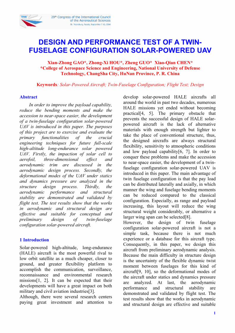
effect of aerofoil must be considered in the design of UAV[12]. In order to study the 3D effect of aerofoil, the CFD numerical method is taken. The full Navier-Stokes equations are discretised and numerically integrated based on a finite-volume approach. According to accuracy and convergence, the computational grid of 3D aerofoil is determined, as shown in Fig.4. The grid is the C-H pattern, the boundary condition is set according to attack angle of aerofoil.
Fig. 4 Computational grid of 3D aerofoil
-5
5
10
X
Y
Z
Pressure: -30 -25 -20 -15 -10 -5 0 5 10 15 Pa
Fig. 5 Lateral distributions of pressure coefficient
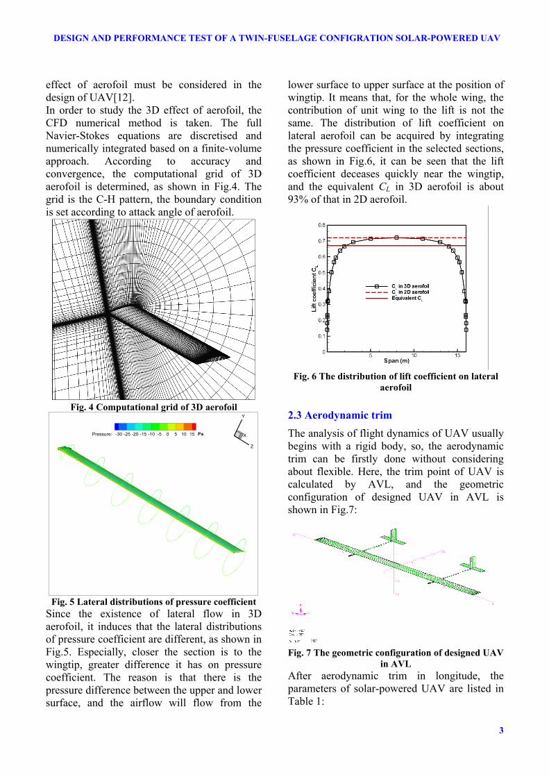
Since the existence of lateral flow in 3D aerofoil, it induces that the lateral distributions of pressure coefficient are different, as shown in Fig.5. Especially, closer the section is to the wingtip, greater difference it has on pressure coefficient. The reason is that there is the pressure difference between the upper and lower surface, and the airflow will flow from the
lower surface to upper surface at the position of wingtip. It means that, for the whole wing, the contribution of unit wing to the lift is not the same. The distribution of lift coefficient on lateral aerofoil can be acquired by integrating the pressure coefficient in the selected sections, as shown in Fig.6, it can be seen that the lift coefficient deceases quickly near the wingtip, and the equivalent CL in 3D aerofoil is about 93% of that in 2D aerofoil.
Fig. 6 The distribution of lift coefficient on lateral
aerofoil
2.3 Aerodynamic trim
The analysis of flight dynamics of UAV usually begins with a rigid body, so, the aerodynamic trim can be firstly done without considering about flexible. Here, the trim point of UAV is calculated by AVL, and the geometric configuration of designed UAV in AVL is shown in Fig.7:
Fig. 7 The geometric configuration of designed UAV
in AVL After aerodynamic trim in longitude, the parameters of solar-powered UAV are listed in Table 1:

Xian-Zhong GAO, Zhong-Xi HOU et al
4
Table 1 The parameters of solar-powered UAV after aerodynamic trim
Parameters Values Setting angle of the wing αw = 2.70°
Setting angle of the elevator αele = -0.23° Lift coefficient CL = 0.80
Pitch moment coefficient Cm = 1.00E-5 Position of gravity center 33.33% length of mean
chord Margin of static stability 26.54% length of mean
chord
3 Structure Analysis
3.1 Statics analysis
For high aspect-ratio solar-powered UAV, the wing skin approximates the aerodynamic shape and is stiffened by ribs, spars and longitudinal stringers[9]. Static aeroelastic effects generate significant structural deformation, thus, the configuration in flight is significantly different from the initial undeformed shape[13]. In order to study the structural behavior, the predicted aerodynamic pressure from the above fine CFD surface grid in Fig.4 is projected on to the coarser finite-element structural mesh, as shown in Fig.8
Fig. 8 The predicted aerodynamic pressure is
projected on to the finite-element structural mesh Result for the deformation of solar-powered UAV is shown in Fig.9:
Fig. 9 The deformation of solar-powered UAV
Fig.9 shows that the maximum deflection is found to occur at the wing tip, and the total tip deflection is 20.26 cm. The maximum stress along the wing occurs near the fuselage, as shown in Fig.10, the maximum stress is 30.22 MPa.
Fig. 10 Stress distribution along the wing
3.2 Dynamics analysis
The aim of dynamics analysis is to find the natural frequency of solar-power UAV and the main deformed shape of twin fuselage configuration. The result of dynamics analysis is listed in Table 2. From this table, it can be found that, the first, second, and third order mode frequency are below 4Hz, while the mode frequency of wind is always this value, thus, twin fuselage configuration is vulnerable to wind load.
Table 2 The result of dynamics analysis
Order Frequency
1 0.7607
2 2.0190
3 3.6472
4 4.6381
5 5.1235
6 7.1239
7 7.1941
8 9.4971
9 11.647
10 15.910
11 16.236
12 17.269
13 17.679
14 22.529
Fig.11 shows the deformed shape under the first order mode frequency, which indicates that the main deformation is in the torsional modes for the twin fuselage configuration. Due to the stiff non-uniform of wing and large distribution of mass, the structure appears to be stiff in bending. Consequently, in the designing of twin fuselage

5
DESIGN AND PERFORMANCE TEST OF A TWIN-FUSELAGE CONFIGRATION SOLAR-POWERED UAV
configuration UAV, more attention should be paid to the ability of torsion strength.
Fig. 11 The deformed shape under the first order
mode frequency
4 Performance Test
4.1 Test Procedure
After final assembly and system integration, a series of ground tests were scheduled to validate the aerodynamic and structure performance of a 1:4 scaled solar-powered UAV. An outdoor flight was also performed, as shown in Fig.12. The two fuselage configuration solar-powered UAV flew for more than 30 minutes, its tracking performance in the north-east coordinate frame was shown in Fig.13. The controller of aircraft was an off-the-shelf commercial auto-pilot. The scaled UAV was taken off by a ground operator, when the UAV arrived at a certain attitude it was transferred to be controlled by auto-pilot. The primary functionalities of the control system were exercised and evaluated, and the performance of UAV can be tested by its response of inner and outer loop.
Fig. 12 The flight test of scaled UAV
Fig. 13 Flight path of scaled UAV
4.2 Response of inner loop
Fig.14 shows the response of inner loop, it can be seen that the inner loop can track the command very well when the controller is switched to auto-pilot. This indicates that the works in aerodynamic trim process is effective.
Fig. 14 Response of inner loop
4.3 Response of outer loop
Fig.15 shows the response of outer loop, Fig.15-a is altitude response, Fig.15-b is speed response, and Fig.15-c is the heading angle response. Fig.15-a and Fig.15-c indicate that altitude and heading angle of UAV can basically follow the command, whereas Fig14-b suggests

Xian-Zhong GAO, Zhong-Xi HOU et al
6
speed cannot track command very well. The main reason for deviations from the reference velocity and degraded tracking performance during flight test are caused by the delay of airspeed indicator. Another factor influencing the outcome of experiments is that flight test is conducted in the presence of relative strong winds.
Fig. 15 Response of outer loop
5 Summary and Conclusion
The design and performance test of a twin-fuselage configuration solar-powered UAV is introduced in this paper. Several significant achievements have been accomplished in this project, including impaction analysis of solar cell to aerofoil, three-dimensional effect of aerofoil, the method of aerodynamic trim, statics and dynamics analysis on structure design and so on. These engineering techniques are crucial for full-scale twin-fuselage configuration HALE solar-powered UAV. This project is an important practice for more advance eternal UAV design. The results in aerodynamic design and structure analysis can be concluded as follows: The aerofoil with solar cell will bring some fluctuations of pressure coefficient at the connections of short line sections, but just has slight impaction on lift-drag polar, so the influence of solar cell to aerodynamic of aerofoil can be neglected during preliminary design process. For the whole wing, the contribution of unit wing to the lift is not the same, and the lift coefficient deceases quickly near the wingtip. The equivalent CL in 3D aerofoil is about 93% of that in 2D aerofoil. For the statics analysis of structure, the maximum deflection is found to occur at the wing tip, and the total tip deflection is 20.26 cm. The maximum stress along the wing occurs near the fuselage, the maximum stress is 30.22 MPa. For the dynamic analysis of structure, the first, second, and third order mode frequency are below 4Hz, and the main deformation is in the torsional modes for the twin fuselage configuration.
References
[1] Guo, Z., Chen, X. K., and Hou, Z. X., "Development of a Solar Electric Powered UAV for Long Endurance Flight," presented at the 11th AIAA Aviation Technology, Integration, and Operations Conference, Virginia Beach, 2011.
[2] Romeo, G., Frulla, G., and Cestino, E., "HELIPLATL: Design, Aerodynamic, Structural Analysis of Long-Endurance Solar-Powered Stratospheric Platform," Journal of Aircraft, Vol. 41, No. 6, 2004, pp. 1505~1520.

7
DESIGN AND PERFORMANCE TEST OF A TWIN-FUSELAGE CONFIGRATION SOLAR-POWERED UAV
[3] Goraj, Z., "Dynamics of a high altitude long endurance UAV," presented at the ICAS 2000 CONGRESS, 2000.
[4] Noll, T. E., Ishmeal, S. D., and Henwood, B., "Technical Findings, Lessions Learned, and Recommendations Resulting from the Helios Prototype Vehicle Mishap," UAV Design Process/Design Crieria for Structures, 2007, pp. 3.4-1~3.4-18.
[5] Romeo, G., Frulla, G., and Cestino, E., "Design of a high-altitude long-endurance solar-powered unmanned air vehichle for multi-payload and operations," Journal of Aerospace Engineering, Vol. 221, 2007, pp. 199~216.
[6] Noll, T. E., et al., "Investigation of the Helios Protype Aircraft Mishap," 1 2004.
[7] Hajianmaleki, M., "Conceptual Design Method for Solar Powered Aircrafts," presented at the 49th AIAA Aerospace Sciences Meeting including the New Horizons Forum and Aerospace Exposition, Orlando, Florida, 2011.
[8] Udin, S. V. and Anderson, W. J., "Wing Mass formula for Twin Fuselage Aircraft," Journal of Aircraft, Vol. 29, No. 5, 1992, pp. 907~914.
[9] Kaloyanova, V. B., Ghia, K. N., and Ghia, U., "Structural Modeling and Optimization of the Joined Wing of a High-Alititude Long-Endurance (HALE) Aircraft," presented at the 43rd AIAA Aerospaces Sciences Meeting and Exhibit, Reno Nevada, 2005.
[10] Sotoudeh, Z. and Hodges, D. H., "Validation Studies for Aeroelastic Trim and Stability Analysis of Highly Flexible Aircraft," Journal of Aircraft, Vol. 47, No. 4, 2010, pp. 1240~1247.
[11] Rapinett, A., "Zephyr: A High Altitude Long Endurance Unmanned Air Vehicle," Doctor, Department of Physics, University of Surrey, 2009.
[12] Reich, G. W., Bowman, J. C., and Sanders, B., "Large-Area Aerodynamic Control for High-Altitude Long-Endurance Sensor Platforms," Journal of Aircraft, Vol. 42, No. 1, 2005, pp. 237~245.
[13] Shearer, C. M. and Cesnik, C. E. S., "Nonlinear Flight Dynamics of Very Flexible Aircraft," Journal of Aircraft, Vol. 44, No. 5, 2007, pp. 1528~1545.
Copyright Statement The authors confirm that they, and/or their company or organization, hold company right on all of the original material included in this paper, to publish it as part of their paper. The authors confirm that they give permission, or have obtained permission from the copyright holder of this paper, for the publication and distribution of this paper as part of the ICAS 2014 proceedings or as individual off-prints from the proceedings.