design and performance characteristics of digital ... · • screen-film radiography – iq...
TRANSCRIPT

1
Design and Performance Characteristics of Digital Radiographic Receptors
Design and Performance Characteristics Design and Performance Characteristics of Digital Radiographic Receptorsof Digital Radiographic Receptors
J. Anthony Seibert, Ph.D.University of California, Davis Medical Center
Sacramento, California
J. Anthony Seibert, Ph.D.J. Anthony Seibert, Ph.D.University of California, Davis Medical CenterUniversity of California, Davis Medical Center
Sacramento, CaliforniaSacramento, California
Learning ObjectivesLearning ObjectivesLearning Objectives
• Describe digital detector technologies for radiography and mammography
• Review functional attributes
• Compare detectors in terms of IQ and dose
• Summarize advantages/disadvantages
•• Describe digital detector technologies for Describe digital detector technologies for radiography and mammographyradiography and mammography
•• Review functional attributesReview functional attributes
•• Compare detectors in terms of IQ and doseCompare detectors in terms of IQ and dose
•• Summarize advantages/disadvantagesSummarize advantages/disadvantages
Presentation OutlinePresentation OutlinePresentation Outline
• Acquisition System Overview
• Digital Detector Attributes
• Digital Detector Technologies
• Factors affecting Image Quality & Dose
• Clinical Implementation and QC
•• Acquisition System OverviewAcquisition System Overview
•• Digital Detector AttributesDigital Detector Attributes
•• Digital Detector TechnologiesDigital Detector Technologies
•• Factors affecting Image Quality & DoseFactors affecting Image Quality & Dose
•• Clinical Implementation and QCClinical Implementation and QC

2
DetectorEfficiencyResolutionScatter grid
DQE
DetectorDetectorEfficiencyEfficiencyResolutionResolutionScatter gridScatter grid
DQEDQE
Image acquisition, display, & interpretationImage acquisition, display, & interpretationImage acquisition, display, & interpretation
X-rayskVpmAs
Tube filtrationCollimation
XX--raysrayskVpkVpmAsmAs
Tube filtrationTube filtrationCollimationCollimation
PatientSize
RestraintsExam typeESE, dose
PatientPatientSizeSize
RestraintsRestraintsExam typeExam typeESE, doseESE, dose
HumanRadiologistPhysician
ExperienceCondition
HumanHumanRadiologistRadiologistPhysicianPhysician
ExperienceExperienceConditionCondition
ComputerDigitization
PreprocessingPostprocessingConfiguration
ComputerComputerDigitizationDigitization
PreprocessingPreprocessingPostprocessingPostprocessingConfigurationConfiguration
PACSData deliveryData displayData storage
Workflow
PACSPACSData deliveryData deliveryData displayData displayData storageData storage
WorkflowWorkflow
Acquisition to Interpretation: Image QualityAcquisition to Interpretation: Image QualityAcquisition to Interpretation: Image Quality
• Image quality is an indicator of the relevance of information presented in the image to the task we seek to accomplish using the image
• Considered in terms of portrayal of – Normal anatomy– Depiction of potential pathology
• Not necessarily the “same” in all images
• A constraining factor is radiation dose
•• Image quality is an indicator of the relevance Image quality is an indicator of the relevance of information presented in the image to the of information presented in the image to the task we seek to accomplish using the imagetask we seek to accomplish using the image
•• Considered in terms of portrayal of Considered in terms of portrayal of –– Normal anatomyNormal anatomy–– Depiction of potential pathologyDepiction of potential pathology
•• Not necessarily the Not necessarily the ““samesame”” in all imagesin all images
•• A constraining factor is radiation doseA constraining factor is radiation dose
Image QualityImage QualityImage Quality
• Screen-film radiography– IQ “built in” to the characteristics of the film– Film is acquisition, display and archive medium– Dose is determined by screen-film speed
• Digital radiography– IQ dependent on Signal to Noise Ratio (SNR)– Separation of acquisition, display, and archive– Dose is variable and dependent on required SNR
•• ScreenScreen--film radiographyfilm radiography–– IQ IQ ““built inbuilt in”” to the characteristics of the filmto the characteristics of the film–– Film is acquisition, display and archive mediumFilm is acquisition, display and archive medium–– Dose is determined by screenDose is determined by screen--film speedfilm speed
•• Digital radiographyDigital radiography–– IQ dependent on Signal to Noise Ratio (SNR)IQ dependent on Signal to Noise Ratio (SNR)–– Separation of acquisition, display, and archiveSeparation of acquisition, display, and archive–– Dose is variable and dependent on required SNRDose is variable and dependent on required SNR

3
Presentation OutlinePresentation OutlinePresentation Outline
• Acquisition System Overview
• Digital Detector Attributes
• Digital Detector Technologies
• Factors affecting Image Quality & Dose
• Clinical Implementation and QC
•• Acquisition System OverviewAcquisition System Overview
•• Digital Detector AttributesDigital Detector Attributes
•• Digital Detector TechnologiesDigital Detector Technologies
•• Factors affecting Image Quality & DoseFactors affecting Image Quality & Dose
•• Clinical Implementation and QCClinical Implementation and QC
Gray ScaleGray Scaleencoded on encoded on
filmfilm
Film processing: Film processing: light to optical densitylight to optical density
Log Relative ExposureLog Relative Exposure
Opt
ical
Den
sity
Opt
ical
Den
sity
Conventional screen/film detectorConventional screen/film detector
FilmFilm Intensifying Screens Intensifying Screens xx--rays rays →→ lightlight
Transmitted xTransmitted x--raysraysthrough patientthrough patient
1. Acquisition, Display, Archiving1. Acquisition, Display, Archiving
Digital XDigital X--ray Detectorray Detector
Transmitted xTransmitted x--raysraysthrough patientthrough patient
Charge Charge collection collection
devicedevice
XX--ray converterray converterxx--rays rays →→ electronselectrons
Analog to DigitalAnalog to DigitalConversionConversion
1. Acquisition1. Acquisition
2. Display2. Display
3. Archiving3. Archiving
Digital Digital processingprocessing
Digital to AnalogDigital to AnalogConversionConversion
Digital PixelDigital PixelMatrixMatrix

4
Exposure LatitudeExposure Latitude
Log relative exposureLog relative exposure
Sig
nal o
utpu
tS
igna
l out
put
10000:110000:1
DigitalDigital
Spatial ResolutionSpatial ResolutionAnalog versus DigitalAnalog versus Digital
MTF of pixel aperture (DEL)
00.10.20.30.40.50.60.70.80.9
1
0 1 2 3 4 5 6 7 8 9 10 11Frequency (lp/mm)
Mod
ulat
ion
1000 µm
200 µm
100 µm
DetectorDetectorElement,Element,
““DELDEL””SamplingSamplingPitchPitch
FilmFilm
100:1100:1
Digital DetectorsDigital DetectorsDigital Detectors
• Separation of acquisition, display and archive
• Digital acquisition is not contrast limited– Image processing
• Signal to Noise Ratio (SNR) and Contrast to Noise Ratio (CNR) impacts “image quality”
• Detector DQE determines the exposure required to achieve a required SNR
•• Separation of acquisition, display and archiveSeparation of acquisition, display and archive
•• Digital acquisition is Digital acquisition is not contrast limitednot contrast limited–– Image processingImage processing
•• Signal to Noise Ratio (SNR) and Contrast to Signal to Noise Ratio (SNR) and Contrast to Noise Ratio (CNR) impacts Noise Ratio (CNR) impacts ““image qualityimage quality””
•• Detector DQE determines the exposure required Detector DQE determines the exposure required to achieve a required SNRto achieve a required SNR
Digital DetectorsDigital DetectorsDigital Detectors
• Sampling and quantization (new noise sources)
• Detector pre-processing (correct imperfections)
• Image post-processing (enhance image contrast)
•• Sampling and quantization (new noise sources)Sampling and quantization (new noise sources)
•• Detector preDetector pre--processing (correct imperfections)processing (correct imperfections)
•• Image postImage post--processing (enhance image contrast)processing (enhance image contrast)
5
Presentation OutlinePresentation OutlinePresentation Outline
• Acquisition System Overview
• Digital Detector Attributes
• Digital Detector Technologies
• Factors affecting Image Quality & Dose
• Clinical Implementation and QC
•• Acquisition System OverviewAcquisition System Overview
•• Digital Detector AttributesDigital Detector Attributes
•• Digital Detector TechnologiesDigital Detector Technologies
•• Factors affecting Image Quality & DoseFactors affecting Image Quality & Dose
•• Clinical Implementation and QCClinical Implementation and QC
Digital Detector TechnologiesDigital Detector TechnologiesDigital Detector Technologies
• Photostimulable Storage Phosphor (PSP or CR)
• Charge Coupled Device (CCD)
• Complementary MetalOxide Semiconductor (CMOS)
• Thin-Film-Transistor array (TFT)
• Photon counters (not discussed)
•• Photostimulable Storage Phosphor (PSP or CR)Photostimulable Storage Phosphor (PSP or CR)
•• Charge Coupled Device (CCD)Charge Coupled Device (CCD)
•• Complementary Complementary MetalOxideMetalOxide Semiconductor (CMOS)Semiconductor (CMOS)
•• ThinThin--FilmFilm--Transistor array (TFT) Transistor array (TFT)
•• Photon counters (not discussed)Photon counters (not discussed)
Computed Radiography (CR)Computed Radiography (CR)Computed Radiography (CR)...is the generic term applied to an imaging system
comprised of:
Photostimulable Storage Phosphorto acquire the x-ray projection image
CR Readerto extract the electronic latent image
Digital electronicsto convert the signals to digital form
...is the generic term applied to an imaging system ...is the generic term applied to an imaging system comprised of:comprised of:
Photostimulable Storage PhosphorPhotostimulable Storage Phosphorto acquire the xto acquire the x--ray projection imageray projection image
CR ReaderCR Readerto extract the electronic latent imageto extract the electronic latent image
Digital electronicsDigital electronicsto convert the signals to digital formto convert the signals to digital form

6
CR DetectorCR DetectorCR Detector
• Photostimulable Storage Phosphor (PSP)• Direct replacement for S/F; positioning flexibility•• Photostimulable Storage Phosphor (PSP)Photostimulable Storage Phosphor (PSP)•• Direct replacement for S/F; positioning flexibilityDirect replacement for S/F; positioning flexibility
Phosphor PlatePhosphor PlatePhosphor Plate Cassette HolderCassette HolderCassette Holder
CR Image AcquisitionCR Image AcquisitionCR Image Acquisition
Phosphor platePhosphor plate
XX--rayraysystemsystem
1.1. XX--ray Exposureray Exposure
ImageImageScalingScaling
3.3.ImageImageRecordRecord
4.4.
PatientPatientComputedComputed
RadiographRadiograph5.5.
unexposedunexposed
ImageImageReaderReader
2.2.
exposedexposed
Display / ArchiveDisplay / Archive
Laser film printerLaser film printer
DICOM / PACSDICOM / PACS
Image AcquisitionImage Acquisition
Latent image producedLatent image produced
CRCRReaderReader
Latent Latent image image
extractedextracted
CR QC CR QC WorkstationWorkstationPatient information

7
Photostimulated LuminescencePhotostimulated LuminescenceConduction bandConduction band
Valence bandValence band
PSLPSL3.0 eV3.0 eV
ττ EuEu
EuEu 2+2+EuEu 3+3+ //4f 4f 77
8.3 eV8.3 eVLaser Laser
stimulationstimulation
2.0 eV2.0 eV
F/FF/F++
PSLC complexes (F centers) are PSLC complexes (F centers) are created in numbers proportional to created in numbers proportional to incident xincident x--ray intensityray intensity
ee--
ττ tunnelingtunneling
τ τ recombinationrecombination
4f 4f 66 5d5d
phononphonon
CR: How does it work?CR: How does it work?
IncidentIncidentxx--rays rays
ee
Energy Energy Band BaFBrBand BaFBr
300300400400500500600600700700800800
Rel
ativ
e in
tens
ityR
elat
ive
inte
nsity
0.00.0
0.50.5
1.01.0
λλ (nm)(nm)
Energy (eV)Energy (eV)33 442.52.5221.51.5
Stimulation and Emission SpectraStimulation and Emission Spectra
1.751.75
EmissionEmissionStimulationStimulation
DiodeDiode680 nm680 nm
BaFBr: EuBaFBr: Eu2+2+
OpticalOpticalBarrierBarrier
Photostimulated LuminescencePhotostimulated Luminescence
Incident Laser Incident Laser BeamBeam
PMTPMT
Protective LayerProtective Layer
Phosphor LayerPhosphor Layer
Base SupportBase Support
LightLightScatteringScattering
Laser Light SpreadLaser Light Spread
PhotostimulatedPhotostimulatedLuminescenceLuminescence
"Effective" readout diameter"Effective" readout diameter
ExposedExposedImagingImaging
PlatePlate
Light guideLight guidePSLPSLSignalSignal

8
CR: Latent Image ReadoutCR: Latent Image Readout
PMTPMT
Polygonal Polygonal MirrorMirror
LaserLaserSourceSource
Light channeling guideLight channeling guide
Output SignalOutput Signal
ReferenceReferencedetectordetector Cylindrical mirrorCylindrical mirrorff--θθ
lenslens
ADCADC
Laser beam: Laser beam: Scan directionScan direction
Plate translation: Plate translation: SubSub--scan directionscan direction
To imageTo imageprocessorprocessor
ADCADC
x= 1279x= 1279y= 1333y= 1333z= 500z= 500
Scan DirectionScan Direction
SubSub--scan Directionscan Direction
Laser beam deflectionLaser beam deflection
Plate translationPlate translation
TypicalTypical CR resolution:CR resolution:35 x 43 cm 35 x 43 cm ---- 2.5 lp/mm (200 2.5 lp/mm (200 µµm)m)24 x 30 cm 24 x 30 cm ---- 3.3 lp/mm (150 3.3 lp/mm (150 µµm)m)18 x 24 cm 18 x 24 cm ---- 5.0 lp/mm (100 5.0 lp/mm (100 µµm)m)
Screen/film resolution:Screen/film resolution:77--10 lp/mm (80 10 lp/mm (80 µµm m -- 25 25 µµm)m)
Phosphor Plate CyclePhosphor Plate Cycle
PSP PSP
Base supportBase support
reusereuse
plate erasure:plate erasure:remove residual signalremove residual signal
light erasurelight erasure
plate exposure:plate exposure:create latent imagecreate latent image
xx--ray exposureray exposure
plate readout:plate readout:extract latent imageextract latent image
laser beam scanlaser beam scan

9
CR InnovationsCR InnovationsCR Innovations
• High-speed line scan systems (<10 sec)
• Dual-side readout capabilities (increase DQE)
• Structured phosphors
• Mammography applications ????
• Low cost table-top CR readers
•• HighHigh--speed line scan systems (<10 sec)speed line scan systems (<10 sec)
•• DualDual--side readout capabilities (increase DQE)side readout capabilities (increase DQE)
•• Structured phosphorsStructured phosphors
•• Mammography applications ????Mammography applications ????
•• Low cost tableLow cost table--top CR readerstop CR readers
5 sec scan
Laser LineSource
ShapingLens
Linear CCDArray
LensArray
Line excitation PSL
Sub-scanDirection
CR CR ““lineline--scanscan””
Side View
Linear Laser Source
Light Collection Lens
Linear CCDArray
Stationary IP
Charge Coupled Device: CCDCharge Coupled Device: CCDCharge Coupled Device: CCD
• X-rays on scintillator• Light collection: optical or fiberoptical• Emitted light to CCD photo-sensor • Electronic charge created on silicon• Charge transfer moves packets• Charge to voltage conversion & amplification
•• XX--rays on scintillatorrays on scintillator•• Light collection: optical or Light collection: optical or fiberopticalfiberoptical•• Emitted light to CCD photoEmitted light to CCD photo--sensor sensor •• Electronic charge created on siliconElectronic charge created on silicon•• Charge transfer moves packetsCharge transfer moves packets•• Charge to voltage conversion & amplificationCharge to voltage conversion & amplification

10
CCD Charge CollectionCCD Charge CollectionCCD Charge Collection
TransparentTransparentpolysiliconpolysilicon
““gategate”” electrodeelectrode
Silicon dioxideSilicon dioxide
Silicon substrateSilicon substratePhotoPhoto--generatedgeneratedelectronselectrons
--VVoo --VVoo+V+Voo
PotentialPotentialWellWell
PotentialPotentialBarrierBarrier
PotentialPotentialBarrierBarrier
Light photonsLight photons
ee--
ee--ee--ee--ee--ee--ee--
ee--ee-- ee--
ee-- ee--
CCD charge transferCCD charge transferCCD charge transfer
• Voltage potential of gate electrode pushes electrons towards collection amplifiers
• 24 volts bias for good transfer efficiency• Larger pixel dimension has inefficient transfer• Pixel dimensions:
– 8, 10, 15, 20 micron
• Form factor of CCD array very small
•• Voltage potential of gate electrode pushes Voltage potential of gate electrode pushes electrons towards collection amplifierselectrons towards collection amplifiers
•• 24 volts bias for good transfer efficiency24 volts bias for good transfer efficiency•• Larger pixel dimension has inefficient transferLarger pixel dimension has inefficient transfer•• Pixel dimensions:Pixel dimensions:
–– 8, 10, 15, 20 micron8, 10, 15, 20 micron
•• Form factor of CCD array very smallForm factor of CCD array very small
Light emission & Optical couplingLight emission & Optical couplingLight emission & Optical coupling
Lens
Scintillator
CCDCCDDetectorDetector
Large loss of light!!!
Demagnification >10:1
Optical coupling inefficiencyOptical coupling inefficiency
XX--raysrays
LightLight

11
CCD detectorCCD detectorCCD detector• Silicon chip with photosensitive layer•• Silicon chip with photosensitive layerSilicon chip with photosensitive layer
35 cm x 43 cm 2.5 cm
2.5
cm
Optical de-magnificationLens efficiency?
Secondary Quantum Sink
High fill factor ~ 100 %Good light conversion
efficiency (~85%)
5 cm
5 cm
Larger CCD Larger CCD arraysarrays
ScintillatorScintillator
CCD acquisition and readoutCCD acquisition and readoutCCD acquisition and readout
Pixel
Silicondioxide
Electrode
CCD
HorizontalReadout Register
Masking
ParallelParallelclocksclocks
Serial clocksSerial clocks
Serial RegisterSerial Register
CMOSComplementary Metal Oxide Semiconductor
CMOSCMOSComplementary Metal Oxide SemiconductorComplementary Metal Oxide Semiconductor
• “RAM” with photodiode converter
• Random access readout
• Low voltage operation (5V)
• ? NOISE ……
• Large FOV detector available (tiled CMOS)
• High sampling resolution possible
•• ““RAMRAM”” with photodiode converterwith photodiode converter
•• Random access readoutRandom access readout
•• Low voltage operation (5V)Low voltage operation (5V)
•• ? NOISE ? NOISE …………
•• Large FOV detector available (tiled CMOS)Large FOV detector available (tiled CMOS)
•• High sampling resolution possibleHigh sampling resolution possible

12
CMOS detector on a chipCMOS detector on a chip
LATC
HES
CO
UN
TER
DEC
OD
ER
RO
W D
RIV
ERS
COLUMN SIGNAL CONDITIONING
DECODER
COUNTER
LATCHES
TIMINGAND
CONTROL
PIXEL ARRAY
CLKRUN
DEFAULTLOAD
ADDRESSDATA
+5V
VS_OUT
VR_OUT
READ
FRAME
“Tiled” matrix array of CMOS in large FOV
Available:
Array of tiled CMOS sensorsArray of tiled CMOS sensorsArray of tiled CMOS sensors
XraysXrays
ScintillatorScintillator
Fiberoptic plateFiberoptic plate
MicrolensMicrolens opticsoptics
CMOS sensorsCMOS sensors
Controller electronicsController electronics
7000x7000 element array, 177000x7000 element array, 17”” x 17x 17”” FOV for one implementationFOV for one implementation
DeadZone
Amorphous SiliconAmorphous SiliconTFT TFT active matrixactive matrix arrayarray
ThinThin--Film Film Transistor Transistor
Storage Storage CapacitorCapacitor
Charge Charge Collector Collector ElectrodeElectrode
G1G1
G2G2
G3G3
Gate Gate switchesswitches
D2D2D1D1 D3D3
Data linesData linesCR2CR2 CR3CR3CR1CR1
Charge Charge Amplifiers Amplifiers
Analog to Analog to Digital Digital ConvertersConverters
Amplifiers – Signal out
Active Area

13
Amorphous SiliconAmorphous SiliconTFT TFT active matrixactive matrix arrayarray
G1G1
G2G2
G3G3
Expose to xExpose to x--raysrays
Store the chargeStore the charge
Active ReadoutActive ReadoutActivate gatesActivate gatesAmplify chargeAmplify charge
Convert to DigitalConvert to Digital
Amplifiers – Signal out
Indirect detector:Indirect detector:aa--SiSi TFT/ CsI phosphorTFT/ CsI phosphor
GGSS DD
Adjacent gate lineAdjacent gate lineTFTTFTStorage capacitorStorage capacitorPhotodiodePhotodiode
SourceSourceGateGateDrainDrain
Structured XStructured X--ray ray phosphor (CsI)phosphor (CsI)
XX--rayray
LightLight
++
ChargeCharge
XX--rays to light to electrons to electronic signalrays to light to electrons to electronic signal
Direct detector:Direct detector:aa--Se / TFT arraySe / TFT array
Top electrodeTop electrodeDielectric layerDielectric layerSelenium photoconductorSelenium photoconductor
Charge collection electrode Charge collection electrode (pixel size)(pixel size)ThinThin--FilmFilm--TransistorTransistorStorage capacitorStorage capacitorGlass substrateGlass substrate
High High voltagevoltage
Incident xIncident x--raysrays
+- ++ ++ ++
++
--
-- --
----
--
++
--
--++
Stored chargeStored charge
XX--rays to electrons to electronic signalrays to electrons to electronic signal
++ ++++ ++

14
Presentation OutlinePresentation OutlinePresentation Outline
• Acquisition System Overview
• Digital Detector Attributes
• Digital Detector Technologies
• Factors affecting Image Quality & Dose
• Clinical Implementation and QC
•• Acquisition System OverviewAcquisition System Overview
•• Digital Detector AttributesDigital Detector Attributes
•• Digital Detector TechnologiesDigital Detector Technologies
•• Factors affecting Image Quality & DoseFactors affecting Image Quality & Dose
•• Clinical Implementation and QCClinical Implementation and QC
Image acquisition and displayImage acquisition and displayImage acquisition and display
Uncorrected Uncorrected ““RawRaw””
AcquisitionAcquisition
Corrected Corrected ““RawRaw””
PrePre--processingprocessing
““For displayFor display””enhancedenhanced
PostPost--processingprocessing
ImageImagecomparisonscomparisons
DisplayDisplay
XX--ray systemray system-- SpectrumSpectrum-- DetectorDetector
Dead pixelsDead pixelsColumn/line defectsColumn/line defectsShading/flatShading/flat--fieldingfieldingSignal amplificationSignal amplification
Enhancement:Enhancement:-- EqualizationEqualization
-- Contrast/Detail Contrast/Detail
Hard/Soft CopyHard/Soft CopyPerceptual linearizationPerceptual linearizationVOI LUT VOI LUT ---- DICOM GSDFDICOM GSDF
Hanging / ViewingHanging / Viewing
OutsideOutsideimagesimages
??
Signal to Noise Ratio (SNR)Signal to Noise Ratio (SNR)Signal to Noise Ratio (SNR)
• Determines detectability of an object
• The signal is derived from the x-ray quanta
• The noise is from a variety of sources:– X-ray quantum statistics– Electronic noise– Fixed pattern noise– Sampling noise (aliasing)– Anatomical noise
• System pre and post processing are crucial
•• Determines detectability of an objectDetermines detectability of an object
•• The signal is derived from the xThe signal is derived from the x--ray quantaray quanta
•• The noise is from a variety of sources:The noise is from a variety of sources:–– XX--ray quantum statisticsray quantum statistics–– Electronic noiseElectronic noise–– Fixed pattern noiseFixed pattern noise–– Sampling noise (aliasing)Sampling noise (aliasing)–– Anatomical noiseAnatomical noise
•• System pre and post processing are crucialSystem pre and post processing are crucial

15
Pre-ProcessingPrePre--ProcessingProcessing
• Detector / x-ray system flaws– Pixel defects– Sensitivity variations– Offset gain variations
• Wide detector dynamic range– Identify image location– Scale image data– Optimize quantization levels for “post-processing”
•• Detector / xDetector / x--ray system flawsray system flaws–– Pixel defectsPixel defects–– Sensitivity variationsSensitivity variations–– Offset gain variationsOffset gain variations
•• Wide detector dynamic rangeWide detector dynamic range–– Identify image locationIdentify image location–– Scale image dataScale image data–– Optimize quantization levels for Optimize quantization levels for ““postpost--processingprocessing””
Two major steps correct and adjust for: Two major steps correct and adjust for: Two major steps correct and adjust for:
Preprocessing, Step 1: correct flawsPreprocessing, Step 1: correct flawsPreprocessing, Step 1: correct flaws
• Detector origin– stationary patterns (structured), fixed-point noise– thickness non-uniformities – drop-outs, dead pixels, dead columns– dark current variation
• Equipment origin– heel effect– stationary patterns/artifacts (e.g., tube filter, grid)
•• Detector originDetector origin–– stationary patterns (structured), fixedstationary patterns (structured), fixed--point noisepoint noise–– thickness nonthickness non--uniformities uniformities –– dropdrop--outs, dead pixels, dead columnsouts, dead pixels, dead columns–– dark current variationdark current variation
•• Equipment originEquipment origin–– heel effectheel effect–– stationary patterns/artifacts (e.g., tube filter, grid)stationary patterns/artifacts (e.g., tube filter, grid)
Pre-processing schemesPrePre--processing schemesprocessing schemes
• 1-D shading correction– Computed Radiography (CR)– Linear CCD
• 2-D flat-field correction– Area CCD, CMOS – TFT arrays
•• 11--DD shadingshading correctioncorrection–– Computed Radiography (CR)Computed Radiography (CR)–– Linear CCDLinear CCD
•• 22--DD flatflat--fieldfield correctioncorrection–– Area CCD, CMOS Area CCD, CMOS –– TFT arraysTFT arrays

16
n 1, i ; O(x) - I(x) (x)I iiO ==
Shading correction techniques: 1Shading correction techniques: 1--D dataD data
(x)I
I Sh(x)
O
xO=
( ) x)Sh O(x) - I(x) C(x) (×=
Apply offset correction to uniform exposures, n averages:Apply offset correction to uniform exposures, n averages:
Create normalized shading correction array:Create normalized shading correction array:
Implement shading correction (line by line):Implement shading correction (line by line):
1-D shading correction11--D shading correctionD shading correction
ResponseResponse
Low noise, inverted, normalized correction traceLow noise, inverted, normalized correction trace
PrePre--processingprocessing
Corrected responseCorrected response
Scan DirectionScan Direction
2-D flat-field correction22--D flatD flat--field correctionfield correction
• Non-functioning components:– Dead pixels in columns and/or rows
• Intensity variations:– Uneven phosphor coating– Optical coupling (vignetting, barrel distortion)– Converter sensitivity
• Variation in offset and gain of sub-panels
• Variation in black-level correction
•• NonNon--functioning components:functioning components:–– Dead pixels in columns and/or rowsDead pixels in columns and/or rows
•• Intensity variations:Intensity variations:–– Uneven phosphor coatingUneven phosphor coating–– Optical coupling (vignetting, barrel distortion)Optical coupling (vignetting, barrel distortion)–– Converter sensitivityConverter sensitivity
•• Variation in offset and gain of subVariation in offset and gain of sub--panelspanels
•• Variation in blackVariation in black--level correctionlevel correction

17
Uncorrected flat-panel imageUncorrected flatUncorrected flat--panel imagepanel image
+ , + , --column defectscolumn defects
row defectsrow defects
pixel defectspixel defects
SubSub--panel offset gain variationpanel offset gain variation
BackgroundBackgroundsignalsignal
n 1, i ; y)O(x, - y)I(x, y)(x,I iiO ==
FlatFlat--field techniques: 2D imagefield techniques: 2D image(fixed detector)(fixed detector)
y)(x,I I
y)FF(x,O
O=
( ) y)x,FF y)O(x, - y)I(x, y)C(x, (×=
Apply offset and average of <n> uniform exposures:Apply offset and average of <n> uniform exposures:
Create normalized flatCreate normalized flat--field correction matrix:field correction matrix:
Implement flatImplement flat--field correction on acquired image:field correction on acquired image:
2-D Flat-field correction22--D FlatD Flat--field correctionfield correction
Raw, RawRaw, Raw
Background variationsBackground variationsColumn, line defectsColumn, line defects““DelDel”” dropoutsdropouts
Correction Correction ““maskmask””
Avg, inverted backgroundAvg, inverted backgroundColumn, line, pixel repairColumn, line, pixel repairNormalized valuesNormalized values
RawRaw
PrePre--processed imageprocessed imageImage pixel value to Image pixel value to exposure relationship?exposure relationship?
ProcessedProcessed
Contrast, resolution Contrast, resolution enhancement; proprietaryenhancement; proprietaryprocessingprocessing
PrePre--processingprocessing

18
Preprocessing, Step 2: find / scale imagePreprocessing, Step 2: find / scale imagePreprocessing, Step 2: find / scale imageDetermine CollimationDetermine Collimation
CollimationCollimationBorderBorderShift and SubtractShift and Subtract
Create / analyze Histogram DistributionCreate / analyze Histogram DistributionCreate / analyze Histogram Distribution
The shape is dependent on radiographic study, The shape is dependent on radiographic study, positioning and techniquepositioning and technique
AnatomyAnatomy
Freq
uenc
yFr
eque
ncy
Useful signalUseful signal
Collimated Collimated areaarea
Direct Direct xx--ray ray areaarea
Pixel valuePixel value
Data conversionData conversionExposure into digital numberExposure into digital number
200200 600600 1,0001,00000
200200
400400
600600
800800
1,0001,000
Raw Input digital numberRaw Input digital number
Out
put d
igita
l num
ber
Out
put d
igita
l num
ber
Grayscale transformationGrayscale transformationInput to output digital numberInput to output digital number
1010331010--11 101000 101022101011
Exposure inputExposure input
Rel
ativ
e P
SL
Rel
ativ
e P
SL
101011
1010--11
101000
101022
00 511511 10231023Raw Digital OutputRaw Digital Output
HistogramHistogramminmin maxmax
Find the Find the signal signal
1.1. Scale toScale torange range
2.2. Create film Create film looklook--alikealike
3.3.

19
Histogram: pediatric imageHistogram: pediatric image
0
200
400
600
800
0 400 600 800 1000 Digital value
Freq
uenc
y
to 8323to 9368
Useful image range for anatomyUseful image range for anatomy
200
PrePre--processed processed ““rawraw”” imageimage
Scaled and inverted:Scaled and inverted:““For ProcessingFor Processing”” imageimage
Data conversion for overexposureData conversion for overexposureExposure into digital numberExposure into digital number
ExposureExposureinputinput
Rel
ativ
e P
SL
Rel
ativ
e P
SL
00 511511 10231023
Raw Digital OutputRaw Digital Output
(scaled and log amplified)(scaled and log amplified)
Reduce overall gain Reduce overall gain
1010331010--11 101000 101022101011
101011
1010--11
101000
101022
minmin maxmaxoverexposureoverexposure

20
Screen – Film
Digital
Identical exposure
Data conversion for wide latitudeData conversion for wide latitudeExposure into digital number: less kV dependenceExposure into digital number: less kV dependence
Rel
ativ
e P
SL
Rel
ativ
e P
SL
101011
1010--11
101000
101022
00 511511 10231023
Raw Digital OutputRaw Digital Output
(scaled and log amplified)(scaled and log amplified)
ExposureExposureinputinput 1010331010--11 101000 101022101011
Change gradientChange gradient(auto mode)(auto mode)
low kVplow kVp(broad histogram)(broad histogram)
minmin maxmax
Contrast EnhancementContrast EnhancementContrast Enhancement
• Optimize image contrast via non-lineartransformation curves
• Unprocessed images: “subject contrast”
• Proprietary processing:– “Gradation processing” (Fuji)– “Tone scaling” (Kodak)– “MUSICA” (Agfa)– …….. And others by the various manufacturers
•• Optimize image contrast via Optimize image contrast via nonnon--linearlineartransformation curvestransformation curves
•• Unprocessed images: Unprocessed images: ““subject contrastsubject contrast””
•• Proprietary processing:Proprietary processing:–– ““Gradation processingGradation processing”” (Fuji)(Fuji)–– ““Tone scalingTone scaling”” (Kodak)(Kodak)–– ““MUSICAMUSICA”” (Agfa)(Agfa)–– ………….. And others by the various manufacturers.. And others by the various manufacturers

21
Look-up-table transformationLookLook--upup--table transformationtable transformation
Input digital numberInput digital number
Out
put d
igita
l num
ber
Out
put d
igita
l num
ber
00 200200 400400 600600 800800 1,0001,00000
200200
400400
600600
800800
1,0001,000
AAEELLMM
Fuji SystemExample LUTsFuji SystemFuji SystemExample LUTsExample LUTs
RawRaw UnprocessedUnprocessedContrast Contrast EnhancedEnhanced
““For processingFor processing””CADCAD
VOI LUTVOI LUT
““For presentationFor presentation””ProprietaryProprietary
Limited variabilityLimited variability
““PrePre--processedprocessed””No scalingNo scalingNo flatfieldNo flatfield
Types of image output:Types of image output:Types of image output:
VOI LUT: a more flexible approachVOI LUT: a more flexible approachVOI LUT: a more flexible approach
• Value Of Interest Look-Up-Table (DICOM)• Adjustment of contrast, brightness with non-linear
LUT adjustment• Provides for manipulation of raw data
(“For Processing” images)• Universal support (modalities, PACS) not available• Future universal image processing workstation?
•• Value Of Interest LookValue Of Interest Look--UpUp--Table (DICOM)Table (DICOM)•• Adjustment of contrast, brightness with nonAdjustment of contrast, brightness with non--linear linear
LUT adjustmentLUT adjustment•• Provides for manipulation of raw data Provides for manipulation of raw data
((““For ProcessingFor Processing”” images)images)•• Universal support (modalities,Universal support (modalities, PACS) not availablePACS) not available•• Future universal image processing workstation?Future universal image processing workstation?

22
DICOM VOI LUTDICOM VOI LUTDICOM VOI LUT• Configure CR/DX modality to send specific VOI LUT
– Eliminates “burned-in” LUT and potential information loss
• PACS must be able to use and vary VOI LUT
•• Configure CR/DX modality to send specific VOI LUTConfigure CR/DX modality to send specific VOI LUT–– Eliminates Eliminates ““burnedburned--inin”” LUT and potential information lossLUT and potential information loss
•• PACS must be able to use and vary VOI LUT PACS must be able to use and vary VOI LUT
Raw image histogram valuesRaw image histogram values P P -- valuesvalues
40954095
00
Adjustable VOI LUT
Adapted from Mike Flynn presentationAdapted from Mike Flynn presentation
Spatial Frequency ProcessingSpatial Frequency ProcessingSpatial Frequency Processing
“Edge Enhancement”““Edge EnhancementEdge Enhancement””
OriginalOriginal BlurredBlurred
DifferenceDifference Edge enhancedEdge enhancedSpatial frequencySpatial frequency
MTF: original responseMTF: original response
Res
pons
eR
espo
nse
lowlow highhigh
Spatial frequencySpatial frequency
Solid: original responseSolid: original response
Dash: low pass filteredDash: low pass filtered
Res
pons
eR
espo
nse
lowlow highhigh
Spatial frequencySpatial frequency
Original Original -- filteredfiltered
Difference:Difference:
lowlow highhigh
Spatial frequencySpatial frequency
SumSum
lowlow
Difference + OriginalDifference + Original
Edge Enhanced:Edge Enhanced:
highhigh
NonNon--linear linear weightingweighting
NonNon--linear linear weightingweighting
NonNon--linear linear weightingweighting
NonNon--linear linear weightingweighting
““Multi frequencyMulti frequency””enhanced imageenhanced image
Optimize subOptimize sub--band weightingband weighting
Multi-band Frequency ProcessingMultiMulti--band Frequency Processingband Frequency Processing

23
Standard ProcessingStandard Processing MultiMulti--frequency Processingfrequency Processing
Compliments of Keith Strauss, Boston Compliments of Keith Strauss, Boston ChildrensChildrens HospitalHospital
SNR and CNR (dSNR)SNR and CNR (SNR and CNR (dSNRdSNR))
• SNR: Average value / Std Dev of background
• CNR: ∆ Attenuation / Std Dev of background
– Contrast: tissue differences, tissue/bone differences
– Subject contrast: X-ray energy
• Detection: CNR of 3 to 5 – Size (diameter); image processing
•• SNR: Average value / Std Dev of backgroundSNR: Average value / Std Dev of background
•• CNR: CNR: ∆∆ Attenuation / Std Dev of backgroundAttenuation / Std Dev of background
–– Contrast: tissue differences, tissue/bone differencesContrast: tissue differences, tissue/bone differences
–– Subject contrast: XSubject contrast: X--ray energyray energy
•• Detection: CNR of 3 to 5 Detection: CNR of 3 to 5 –– Size (diameter); image processingSize (diameter); image processing
SNR and CNRSNR and CNRSNR and CNR
BackgroundBackground420.3 420.3 ±±3.33.3
ObjectObject411.8 411.8 ±±3.33.3
420.3SNR = = 127.43.3
420.3 - 411.8CNR = = 2.63.3

24
Noise SourcesNoise SourcesNoise Sources• Incomplete x-ray absorption: η• Secondary quantum noise: quantum sink
– # secondary quanta ≤ incident q
• Spatial gain variation (flat-field)• Aliasing (insufficient sampling)• Swank Factor
– Different x-ray photons produce variable signal
• Lubberts Effect– Different x-ray photons produce variable PSF’s
• Additive system noise– Electronic, quantization, shot, etc.
•• Incomplete xIncomplete x--ray absorption: ray absorption: ηη•• Secondary quantum noise: quantum sinkSecondary quantum noise: quantum sink
–– # secondary quanta # secondary quanta ≤≤ incident incident qq
•• Spatial gain variation (flatSpatial gain variation (flat--field)field)•• Aliasing (insufficient sampling)Aliasing (insufficient sampling)•• Swank Factor Swank Factor
–– Different xDifferent x--ray photons produce variable signalray photons produce variable signal
•• LubbertsLubberts EffectEffect–– Different xDifferent x--ray photons produce variable ray photons produce variable PSFPSF’’ss
•• Additive system noiseAdditive system noise–– Electronic, quantization, shot, etc.Electronic, quantization, shot, etc.
Visual Detection of ObjectVisual Detection of ObjectVisual Detection of Object
• SNR (CNR) is x-ray quanta dependent• Detection is determined by CNR and object size
• k = SNR × d × C
C = contrastd = diameterk = 3 to 5 for detection
•• SNR (CNR) is xSNR (CNR) is x--ray quanta dependentray quanta dependent•• Detection is determined by CNR and object sizeDetection is determined by CNR and object size
•• k = SNR k = SNR ×× d d ×× CC
C = contrastC = contrastd = diameterd = diameterk = 3 to 5 for detectionk = 3 to 5 for detection
Low Contrast Response: Leeds TO-16Low Contrast Response: Leeds TOLow Contrast Response: Leeds TO--1616
0.5 mR0.5 mR0.5 mR3.5 mR3.5 mR3.5 mR 70 kVp70 kVp70 kVp

25
What determines necessary dose?What determines What determines necessarynecessary dose?dose?
• Patient thickness
• X-ray technique; GRID or NO GRID
• Detector absorption AND conversion efficiency
• Detector electronic and stationary noise
• Detector Detective Quantum Efficiency (DQE)
• Required SNR / CNR of examination
• Pre and post processing algorithms
• Display and viewing conditions
•• Patient thicknessPatient thickness
•• XX--ray technique; GRID or NO GRIDray technique; GRID or NO GRID
•• Detector absorption Detector absorption AND AND conversion efficiencyconversion efficiency
•• Detector electronic and stationary noiseDetector electronic and stationary noise
•• Detector Detective Quantum Efficiency (DQE)Detector Detective Quantum Efficiency (DQE)
•• Required SNR / CNR of examinationRequired SNR / CNR of examination
•• Pre and post processing algorithmsPre and post processing algorithms
•• Display and viewing conditionsDisplay and viewing conditions
0102030405060708090
100
10 20 30 40 50 60 70 80 90 100 110 120 130 140
Energy (keV)
% A
bsor
ptio
n Fr
actio
n
CsI: 175 mg/cm2
Gd2O2S: 120 mg/cm2
BaFBr: 100 mg/cm2
X-ray absorption Efficiency: CsI, BaFBr, Gd2O2S
Detective Quantum Efficiency (DQE)Detective Quantum Efficiency (DQE)Detective Quantum Efficiency (DQE)
• A measure of the information transfer efficiency of a detector system
• Dependent on:– Absorption efficiency– Conversion efficiency– Spatial resolution (MTF)– Conversion noise– Electronic noise– Detector non-uniformities / pattern noise
•• A measure of the A measure of the information transfer information transfer efficiency efficiency of a detector systemof a detector system
•• Dependent on:Dependent on:–– Absorption efficiencyAbsorption efficiency–– Conversion efficiencyConversion efficiency–– Spatial resolution (MTF)Spatial resolution (MTF)–– Conversion noiseConversion noise–– Electronic noiseElectronic noise–– Detector nonDetector non--uniformities / pattern noiseuniformities / pattern noise
2 2out2in N
SNR MTF( )DQE( ) =SNR NPS ( )
fff q
=×
2 2out2in N
SNR MTF( )DQE( ) =SNR NPS ( )
fff q
=×

26
“Pre-sampled” MTF““PrePre--sampledsampled”” MTFMTF
aa--Selenium: 0.13 mmSelenium: 0.13 mm
ScreenScreen--filmfilm
CsICsI--TFT: 0.20 mmTFT: 0.20 mm
CR: 0.10 mmCR: 0.10 mm0.00.0
0.10.1
0.20.2
0.30.3
0.40.4
0.50.5
0.60.6
0.70.7
0.80.8
0.90.9
1.01.0
0.00.0 0.50.5 1.51.5 2.52.5 3.53.5 4.54.51.01.0 2.02.0 3.03.0 4.04.0 5.05.0Frequency (lp/mm)Frequency (lp/mm)
Mod
ulat
ion
Mod
ulat
ion
CR: 0.05 mmCR: 0.05 mm
Noise Power SpectrumNoise Power SpectrumNoise Power Spectrum
• Noise transfer characteristics of detector
• Analyze sub-images, Fourier Transform, average – (IEC 62220-1 standard, AAPM Task Group on NPS)
• Output is the noise power estimate as a function of spatial frequency, NPS(f) in 2 dimensions
•• Noise transfer characteristics of detectorNoise transfer characteristics of detector
•• Analyze subAnalyze sub--images, Fourier Transform, average images, Fourier Transform, average –– (IEC 62220(IEC 62220--1 standard, AAPM Task Group on NPS)1 standard, AAPM Task Group on NPS)
•• Output is the noise power estimate as a function Output is the noise power estimate as a function of spatial frequency, of spatial frequency, NPS(NPS(ff) in 2 dimensions ) in 2 dimensions
CR Image NPSCR Image NPSScan directionScan direction
DQ
E(
f )
Spatial Frequency (cycles/mm)0.0 0.5 1.0 1.5 2.0 2.5
0.0
0.2
0.4
0.6
0.8CsI - TFT
Screen-film
CR Conventional
a-Se - TFT
CR “dual-side”
Detective Quantum Efficiency, Radiography
CCD
27
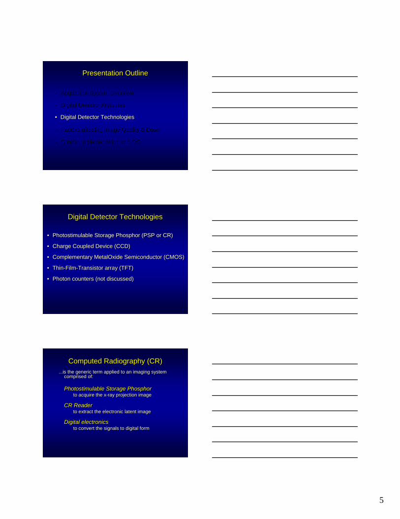
ScreenScreen--FilmFilm
aSiaSi/CsI Flat/CsI Flat--PanelPanel
CRCR
125 kVp125 kVp2 mAs2 mAs
MDACC: Chris Shaw, et alMDACC: Chris Shaw, et al
FlatFlat--field prefield pre--processingprocessing
Low contrastLow contrastresolutionresolution
Image quality depends on more than Image quality depends on more than quantum mottle!quantum mottle!
FlatFlat--field, absorption efficiency, scatter field, absorption efficiency, scatter ……
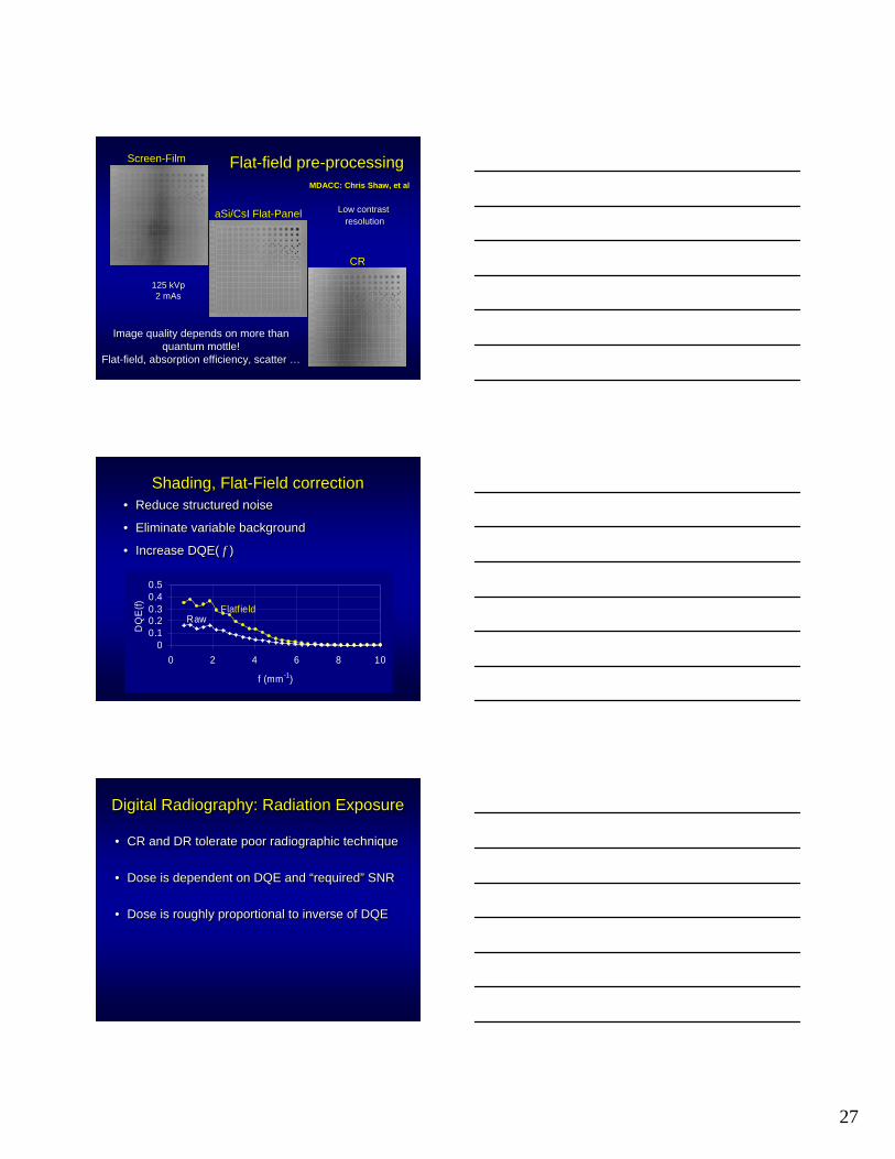
Shading, Flat-Field correctionShading, FlatShading, Flat--Field correctionField correction• Reduce structured noise
• Eliminate variable background
• Increase DQE( f )
•• Reduce structured noiseReduce structured noise
•• Eliminate variable backgroundEliminate variable background
•• Increase DQE( Increase DQE( f f ))
00.10.20.30.40.5
0 2 4 6 8 10
f (mm-1)
DQ
E(f) Flatfield
Raw
Digital Radiography: Radiation ExposureDigital Radiography: Radiation ExposureDigital Radiography: Radiation Exposure
• CR and DR tolerate poor radiographic technique
• Dose is dependent on DQE and “required” SNR
• Dose is roughly proportional to inverse of DQE
•• CR and DR tolerate poor radiographic techniqueCR and DR tolerate poor radiographic technique
•• Dose is dependent on DQE and Dose is dependent on DQE and ““requiredrequired”” SNRSNR
•• Dose is roughly proportional to inverse of DQEDose is roughly proportional to inverse of DQE

28
Exposure issuesExposure issuesExposure issues
• Incident exposure can be “hidden”
• Low exposures have excessive image noise
• High exposures lead to saturation signal loss
• Technique complacency, instead of “just enough”
• Feedback is necessary!! – S number, Exposure Index, LgM, f-number, other?
•• Incident exposure can be Incident exposure can be ““hiddenhidden””
•• Low exposures have excessive image noiseLow exposures have excessive image noise
•• High exposures lead to saturation signal lossHigh exposures lead to saturation signal loss
•• Technique complacency, instead of Technique complacency, instead of ““just enoughjust enough””
•• Feedback is necessary!! Feedback is necessary!! –– S number, Exposure Index, S number, Exposure Index, LgMLgM, f, f--number, other?number, other?
DigitalDigitalFilmFilm--screenscreen(400 speed)(400 speed)
0.01 0.1 1 10 1001
10
100
1,000
10,000
Exposure, mR
Rel
ativ
e in
tens
ity
Film
Opt
ical
Den
sity
0
1
2
3
4
20000 2000 200 20 2 Sensitivity (S)
UnderexposedUnderexposed
OverexposedOverexposed
Correctly exposedCorrectly exposed
Characteristic Curve:Response of screen/film vs. digital detectors
UselessUseless
UselessUseless5
How do manufacturers indicate estimated exposure?
How do manufacturers indicate How do manufacturers indicate estimated exposure?estimated exposure?
• Fuji: “S” – sensitivity number• S ≅ 200 / Exposure (mR)
• Kodak: “Exposure Index” – EI• EI ≅ 1000 × log (Exposure [mR] ) + 2000
• Agfa: “lg M” – relative exposure database
• IDC: “f-number” – provides analogy to camera speed• +1 = 2x exposure; +2 = 4x exposure
• DR: most systems currently do not have a feedback signal… but use phototiming (AEC)
•• Fuji: Fuji: ““SS”” –– sensitivity numbersensitivity number•• S S ≅≅ 200 / Exposure (mR)200 / Exposure (mR)
•• Kodak: Kodak: ““Exposure IndexExposure Index”” –– EIEI•• EI EI ≅≅ 1000 1000 ×× log (Exposure [mR] ) + 2000 log (Exposure [mR] ) + 2000
•• Agfa: Agfa: ““lglg MM”” –– relative exposure databaserelative exposure database
•• IDC: IDC: ““ff--numbernumber”” –– provides analogy to camera speedprovides analogy to camera speed•• +1 = 2x exposure; +2 = 4x exposure+1 = 2x exposure; +2 = 4x exposure
•• DR: most systems currently do not have a feedback DR: most systems currently do not have a feedback signalsignal…… but use phototiming (AEC)but use phototiming (AEC)

29
CR vs DR and dose efficiencyCR CR vsvs DR and dose efficiencyDR and dose efficiency
• CR ~ 2X more exposure than a 400 speed film ~200 equivalent speed
• DR DQE(0) values vary substantially (20 - 80%)
• Dose efficiency related to DQE for given SNR
• Slot-scan systems most efficient
•• CR ~ 2X more exposure than a 400 speed film CR ~ 2X more exposure than a 400 speed film ~200 ~200 equivalent equivalent speedspeed
•• DR DQE(0) values vary substantially (20 DR DQE(0) values vary substantially (20 -- 80%)80%)
•• Dose efficiency related to DQE for given SNRDose efficiency related to DQE for given SNR
•• SlotSlot--scan systems most efficientscan systems most efficient
Presentation OutlinePresentation OutlinePresentation Outline
• Acquisition System Overview
• Digital Detector Attributes
• Digital Detector Technologies
• Factors affecting Image Quality & Dose
• Clinical Implementation and QC
•• Acquisition System OverviewAcquisition System Overview
•• Digital Detector AttributesDigital Detector Attributes
•• Digital Detector TechnologiesDigital Detector Technologies
•• Factors affecting Image Quality & DoseFactors affecting Image Quality & Dose
•• Clinical Implementation and QCClinical Implementation and QC
• Modality interface: DICOM & HL-7– PACS, RIS connections, Modality Worklist
• Image Size & Storage considerations• 8 - 32 Mbytes Uncompressed
– 10 - 12 Pixels/mm– Up to 4000 x 4000 x 2 Bytes
• 3 - 13 Mbytes: ~2.5:1 Lossless Compression
• Network Transmission• 100 Mbit/sec minimum
•• Modality interface: DICOM & HLModality interface: DICOM & HL--77–– PACS, RIS connections, PACS, RIS connections, Modality WorklistModality Worklist
•• Image Size & Storage considerationsImage Size & Storage considerations•• 8 8 -- 32 Mbytes Uncompressed32 Mbytes Uncompressed
–– 10 10 -- 12 Pixels/mm12 Pixels/mm–– Up to 4000 x 4000 x 2 BytesUp to 4000 x 4000 x 2 Bytes
•• 3 3 -- 13 Mbytes: ~2.5:1 Lossless Compression13 Mbytes: ~2.5:1 Lossless Compression
•• Network TransmissionNetwork Transmission•• 100 100 MbitMbit/sec minimum/sec minimum
CR/DR implementationCR/DR implementationCR/DR implementation

30
CR/DR implementationCR/DR implementationCR/DR implementation
• Uniformity for CR/DR images and Display
– Acceptance Testing• Measurement of Performance• Correction of Substandard Performance
– Calibration of CR/DR Response (presentation state)
– Calibration of Monitors• Maximum brightness• Look-up-Tables, DICOM GSDF, Part 14
– Periodic Quality Control • Evaluation of resolution, contrast, artifacts• Monitor technologist performance, exposure indices
•• Uniformity for CR/DR images Uniformity for CR/DR images and and DisplayDisplay
–– Acceptance TestingAcceptance Testing•• Measurement of PerformanceMeasurement of Performance•• Correction of Substandard PerformanceCorrection of Substandard Performance
–– Calibration of CR/DR Response (presentation state)Calibration of CR/DR Response (presentation state)
–– Calibration of MonitorsCalibration of Monitors•• Maximum brightnessMaximum brightness•• LookLook--upup--Tables, DICOM GSDF, Part 14Tables, DICOM GSDF, Part 14
–– Periodic Quality Control Periodic Quality Control •• Evaluation of resolution, contrast, artifactsEvaluation of resolution, contrast, artifacts•• Monitor technologist performance, exposure indicesMonitor technologist performance, exposure indices
CR/DR implementationCR/DR implementationCR/DR implementation
• Image Processing optimization– Establish Contrast Scale– Balance Edge Enhancement with perceived noise– Multi-frequency Enhancement parameter
adjustments– Determine DC offset (brightness) for display
monitors
• Provide processing “looks” to Radiologists
• Verify image display conditions– Soft copy and hard copy
•• Image Processing optimizationImage Processing optimization–– Establish Contrast ScaleEstablish Contrast Scale–– Balance Edge Enhancement with perceived noiseBalance Edge Enhancement with perceived noise–– MultiMulti--frequency Enhancement parameter frequency Enhancement parameter
adjustmentsadjustments–– Determine DC offset (brightness) for display Determine DC offset (brightness) for display
monitorsmonitors
•• Provide processing Provide processing ““lookslooks”” to Radiologiststo Radiologists
•• Verify image display conditionsVerify image display conditions–– Soft copy and hard copySoft copy and hard copy
What is emerging as the lead technology?What is emerging as the lead technology?What is emerging as the lead technology?Attribute CR DR CCD
Positioning flexibility **** ** **
Replacement for S/F **** ** **
DQE / dose efficiency ** *** **
Patient throughput * *** **
X-ray system integration ** **** ****
PACS integration ** **** ****
Cost per pat. throughput *** ** ***
Technologist ease of use * *** ***

31
Digital Radiography ConsiderationsDigital Radiography ConsiderationsDigital Radiography Considerations
• Replacement of S/F, aging CR
• High throughput, ambulatory imaging
• Advanced image acquisition and processing– Digital tomosynthesis and CT– Dual energy radiography– Replacement of image intensifiers
• Low dose screening devices with CAD – Lung cancer screening with dual energy– Quantitative bone density analysis?
•• Replacement of S/F, aging CR Replacement of S/F, aging CR
•• High throughput, ambulatory imagingHigh throughput, ambulatory imaging
•• Advanced image acquisition and processingAdvanced image acquisition and processing–– Digital tomosynthesis and CTDigital tomosynthesis and CT–– Dual energy radiographyDual energy radiography–– Replacement of image intensifiersReplacement of image intensifiers
•• Low dose screening devices with CAD Low dose screening devices with CAD –– Lung cancer screening with dual energyLung cancer screening with dual energy–– Quantitative bone density analysis?Quantitative bone density analysis?
ConclusionsConclusions
•• CR is the most CR is the most flexibleflexible and costand cost--effectiveeffective technologytechnology
•• DirectDirect digital radiographic devices have advantages in digital radiographic devices have advantages in efficiency and throughput efficiency and throughput
•• The distinction between CR and DR is blurringThe distinction between CR and DR is blurring–– Portable versus integrated; active versus passivePortable versus integrated; active versus passive–– ““CassetteCassette”” versus versus ““CassettelessCassetteless””
•• All technologies are becoming faster, better, cheaperAll technologies are becoming faster, better, cheaper
•• The digital solution is best accomplished as a The digital solution is best accomplished as a complementary mix of technologiescomplementary mix of technologies