design and operation of the kupol project counter-current ... · merrill-crowe barren solution is...
TRANSCRIPT
Paste 2009 — R.J. Jewell, A.B. Fourie, S. Barrera and J. Wiertz (eds) © 2009 Australian Centre for Geomechanics, Perth, ISBN 978-0-9804185-8-3
Design and Operation of the Kupol Project Counter-Current Decantation Circuit Using Deep Cone Thickeners
F. Schoenbrunn FLSmidth Minerals, United States of America
J. Rajala Kinross Gold, United States of America
C. McCleary FLSmidth Minerals, United States of America
Abstract Kinross Gold’s Kupol Mine elected to use deep cone thickeners for their counter-current decantation (CCD) circuit as well as the grind thickener. Deep cone thickeners are commonly used for CCD circuits in the alumina industry, but this is the first application of that technology outside of alumina. The project started with process testing and proceeded through design, construction and startup. The circuit design incorporated both mechanical and process challenges. Using deep cone thickening allowed the CCD circuit to be installed indoors which was necessary in the arctic environment at Kupol. The deep cone thickener (DCT) performance allowed the CCD circuit to be reduced from six thickeners to five while maintaining the desired recovery. Some of the circuit features include partial pumping of overflow, maintenance access considerations, underflow pumping via centrifugal pumps and shear thinning, interstage mixing, and flocculant dilution design. Data from startup will be included.
1 Introduction Mill operation at the Kupol mine in the Russian Far East began in mid May 2008. The mill flowsheet is designed to treat high grade gold/silver ore using counter-current decantation (CCD) thickening and Merrill-Crowe processing. Thickener sizing and selection for the CCD circuit was consider paramount to the success of the process performance especially with high clay feed at mill start-up.
Extensive laboratory testing and analysis of results led to the selection of deep cone thickeners for the Kupol CCD circuit. The arctic site conditions were also a major factor in the selection of these units.
This paper reviews the engineering aspects of the Kupol CCD thickener circuit from lab testing through design and start-up. The initial plant performance of the CCD circuit is discussed. The Kupol mill is the first precious metals CCD thickener circuit to use deep cone thickeners.
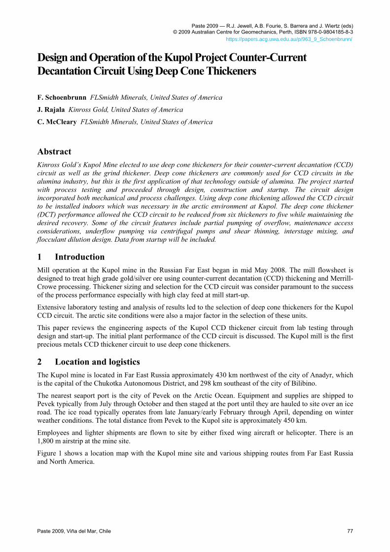
2 Location and logistics The Kupol mine is located in Far East Russia approximately 430 km northwest of the city of Anadyr, which is the capital of the Chukotka Autonomous District, and 298 km southeast of the city of Bilibino.
The nearest seaport port is the city of Pevek on the Arctic Ocean. Equipment and supplies are shipped to Pevek typically from July through October and then staged at the port until they are hauled to site over an ice road. The ice road typically operates from late January/early February through April, depending on winter weather conditions. The total distance from Pevek to the Kupol site is approximately 450 km.
Employees and lighter shipments are flown to site by either fixed wing aircraft or helicopter. There is an 1,800 m airstrip at the mine site.
Figure 1 shows a location map with the Kupol mine site and various shipping routes from Far East Russia and North America.
Paste 2009, Viña del Mar, Chile 77
https://papers.acg.uwa.edu.au/p/963_9_Schoenbrunn/
Design and Operation of the Kupol Project Counter-Current Decantation Circuit Using Deep Cone Thickeners F. Schoenbrunn et al.
Figure 1 Kupol location map with shipping routes to port of Pevek
3 Testing and sizing Testing of about ten different ore samples was conducted over a period of about one year. Variations in pH were also checked to cover possible alternative plant operating ranges. Optimal settling flux rates were initially found to occur at a feed concentration of about 14 wt%, but subsequent testing showed samples where a feed concentration of 8–10 wt% performed better. A flocculant dosage of about 30 gpt was found to be suitable for CCD1. Reflocculation of settled solids, simulating multiple stages of CCD, was tested to insure that the flocculant would be effective after shearing the floc structure. Based on the testing, 14 m deep cone thickeners (DCT) were selected to handle the tonnage and produce underflow densities of 50–55 wt%.
Rheology tests on the settled solids showed yield stresses rising above 50 Pa over a wide range; from 50 to 65 wt% depending on the sample.
4 Selection of DCTs DCTs are a newer alternative which are designed around production of high viscosity muds. They utilise very deep mud beds and steep floors to be able to produce and discharge muds near the limit of pumpability and operate at very high rates in terms of thickener area. Currently these designs are being built up to 40 m diameter although as with many new technologies, larger machines are always on the drawing board.
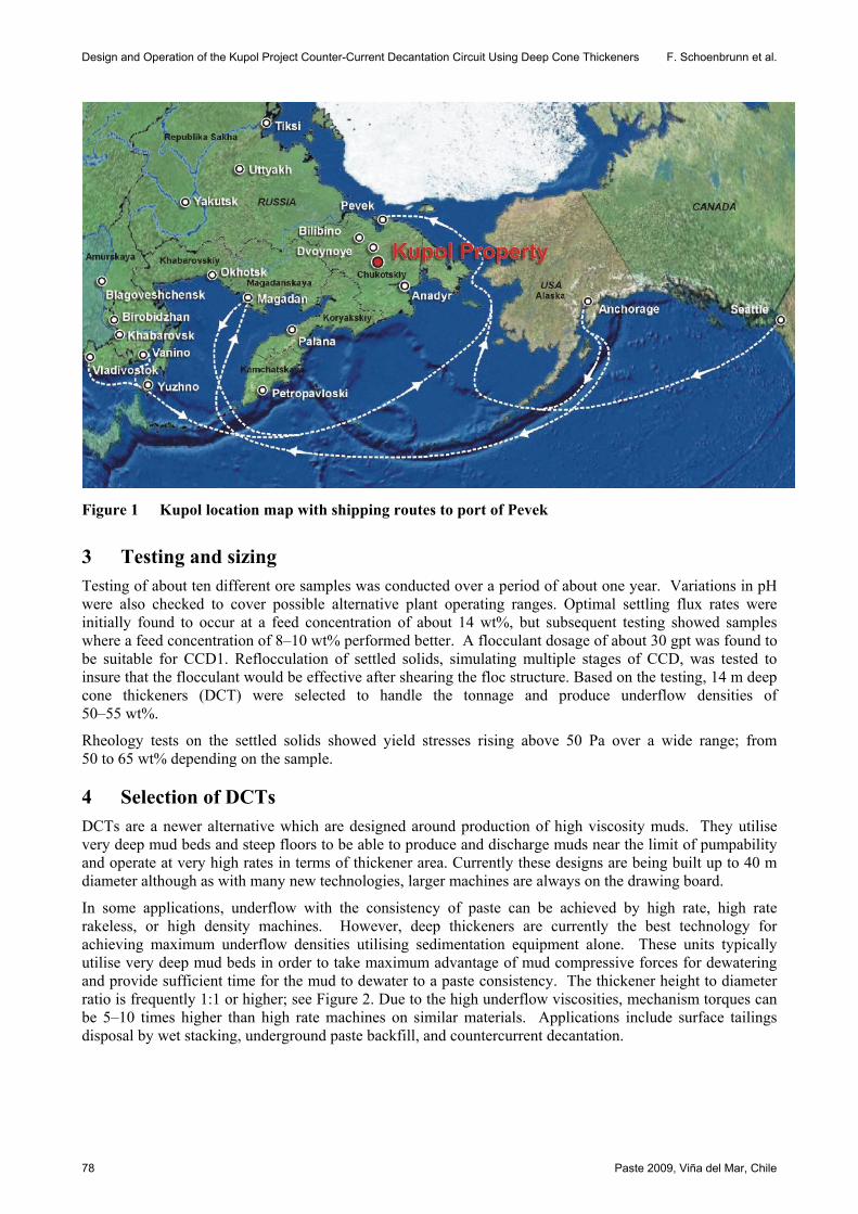
In some applications, underflow with the consistency of paste can be achieved by high rate, high rate rakeless, or high density machines. However, deep thickeners are currently the best technology for achieving maximum underflow densities utilising sedimentation equipment alone. These units typically utilise very deep mud beds in order to take maximum advantage of mud compressive forces for dewatering and provide sufficient time for the mud to dewater to a paste consistency. The thickener height to diameter ratio is frequently 1:1 or higher; see Figure 2. Due to the high underflow viscosities, mechanism torques can be 5–10 times higher than high rate machines on similar materials. Applications include surface tailings disposal by wet stacking, underground paste backfill, and countercurrent decantation.
78 Paste 2009, Viña del Mar, Chile
Thickening
Figure 2 High aspect ratio thickener
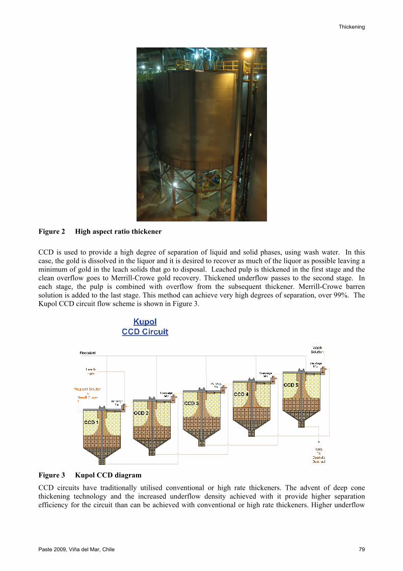
CCD is used to provide a high degree of separation of liquid and solid phases, using wash water. In this case, the gold is dissolved in the liquor and it is desired to recover as much of the liquor as possible leaving a minimum of gold in the leach solids that go to disposal. Leached pulp is thickened in the first stage and the clean overflow goes to Merrill-Crowe gold recovery. Thickened underflow passes to the second stage. In each stage, the pulp is combined with overflow from the subsequent thickener. Merrill-Crowe barren solution is added to the last stage. This method can achieve very high degrees of separation, over 99%. The Kupol CCD circuit flow scheme is shown in Figure 3.
Figure 3 Kupol CCD diagram
CCD circuits have traditionally utilised conventional or high rate thickeners. The advent of deep cone thickening technology and the increased underflow density achieved with it provide higher separation efficiency for the circuit than can be achieved with conventional or high rate thickeners. Higher underflow
Paste 2009, Viña del Mar, Chile 79
Design and Operation of the Kupol Project Counter-Current Decantation Circuit Using Deep Cone Thickeners F. Schoenbrunn et al.
densities allow the same or better overall efficiency using five stages of DCT compared with six stages of high rate thickeners.
The differences noted with the DCT are in the design details which are directed towards achieving this limiting concentration at a very high loading in terms of solids throughput per unit area. Five factors enter into this picture:
• The optimisation of flocculation procedures.
• Relatively deep pulp depth.
• Relatively steep floor slope.
• High torque and raking capacity of the mechanism.
• The use of mechanical devices, such as rakes and pickets, to ‘work’ the compacting slurry.
Deep cone thickeners were originally developed to take advantage of advances in flocculant technology. Good flocculation is a key to the successful operation of a DCT and conditions which promote this action should be followed. This includes selection of the best reagent for the particular slurry, the introduction of the reagent at a very dilute concentration in order to promote better mixing, and most importantly, the optimum solids concentration of the feed slurry. Generally, this concentration is usually lower than the normal process concentration and dilution of the slurry with recycled overflow will be necessary for minimum flocculant use and maximum solids settling rate.
Good flocculation results in the solids passing very rapidly through the normal concentrations associated with ‘zone settling’ which ordinarily would determine the thickener size. In the case of DCTs, the sizing procedures generally must take into account the volume of thick pulp within the thickener, as a substantially longer than normal retention time is necessary for the solids to obtain high concentrations. It is more economical to provide this volume by using a relatively deep bed of pulp rather than a greater area with a shallow compaction bed. This increase in depth also provides bed compression, where the weight of solids above helps compress and dewater the mud to higher concentrations.
The added depth results in greater loads being imposed on the raking mechanism, particularly since the thick mud will be found even at the perimeter of the thickener. This results in a substantial increase in load on the drive and it is necessary to use as much as an order of magnitude more torque for the drive mechanism as would be used on a similarly sized thickener producing a ‘normal’ underflow concentration. In addition, the design criteria for the drive is significantly different from normal minerals duty. The torque is typically consistently high, but not subject to as many peaks.
As the thickened mud approaches a limiting concentration, it becomes less and less like a fluid, and has little tendency to flow to the underflow withdrawal point. Therefore, steep floors of 30 to 60 degrees and rakes designed to overcome the yield stress of the mud are used to transport the thickened mud to the outlet. By contrast, standard thickener design calls for a slope of something less than 10 degrees.
Since the equipment was being installed indoors, the smaller diameter possible with DCTs was an important factor as it helped minimize the size of the building.
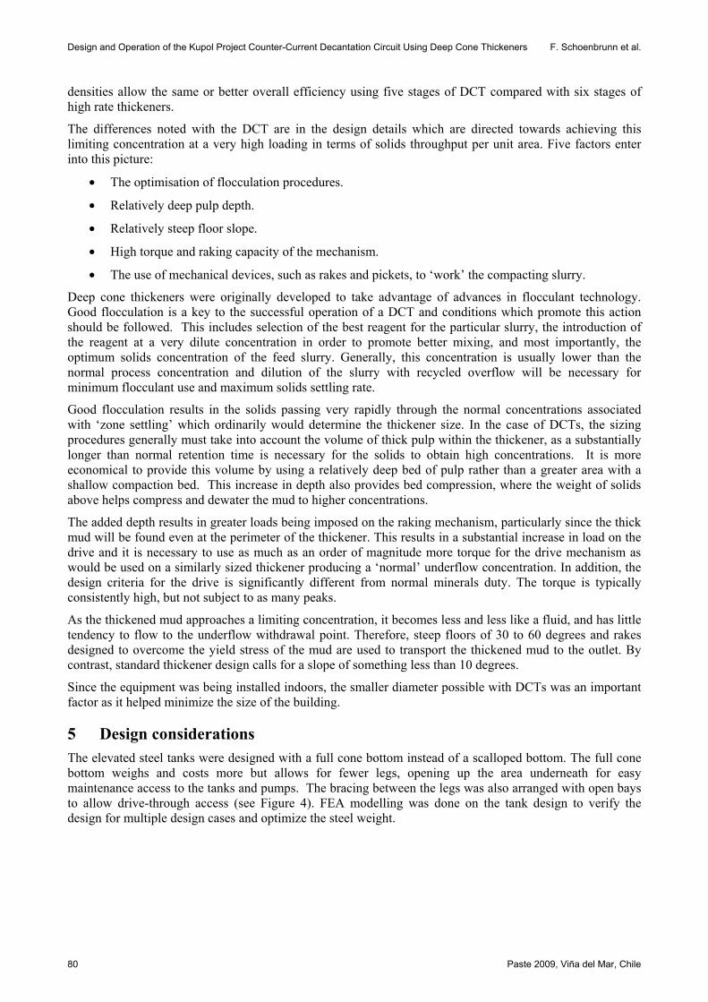
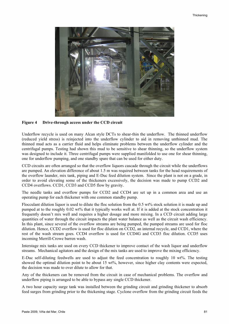
5 Design considerations The elevated steel tanks were designed with a full cone bottom instead of a scalloped bottom. The full cone bottom weighs and costs more but allows for fewer legs, opening up the area underneath for easy maintenance access to the tanks and pumps. The bracing between the legs was also arranged with open bays to allow drive-through access (see Figure 4). FEA modelling was done on the tank design to verify the design for multiple design cases and optimize the steel weight.
80 Paste 2009, Viña del Mar, Chile
Thickening
Figure 4 Drive-through access under the CCD circuit
Underflow recycle is used on many Alcan style DCTs to shear-thin the underflow. The thinned underflow (reduced yield stress) is reinjected into the underflow cylinder to aid in removing unthinned mud. The thinned mud acts as a carrier fluid and helps eliminate problems between the underflow cylinder and the centrifugal pumps. Testing had shown this mud to be sensitive to shear thinning, so the underflow system was designed to include it. Three centrifugal pumps were supplied manifolded to use one for shear thinning, one for underflow pumping, and one standby spare that can be used for either duty.
CCD circuits are often arranged so that the overflow liquors cascade through the circuit while the underflows are pumped. An elevation difference of about 1.5 m was required between tanks for the head requirements of the overflow launder, mix tank, piping and E-Duc feed dilution system. Since the plant is not on a grade, in order to avoid elevating some of the thickeners excessively, the decision was made to pump CCD2 and CCD4 overflows. CCD1, CCD3 and CCD5 flow by gravity.
The needle tanks and overflow pumps for CCD2 and CCD4 are set up in a common area and use an operating pump for each thickener with one common standby pump.
Flocculant dilution liquor is used to dilute the floc solution from the 0.5 wt% stock solution it is made up and pumped at to the roughly 0.02 wt% that it typically works well at. If it is added at the stock concentration it frequently doesn’t mix well and requires a higher dosage and more mixing. In a CCD circuit adding large quantities of water through the circuit impacts the plant water balance as well as the circuit wash efficiency. In this plant, since several of the overflow streams are being pumped, the pumped streams are used for floc dilution. Hence, CCD2 overflow is used for floc dilution on CCD2, an internal recycle, and CCD1, where the rest of the wash stream goes. CCD4 overflow is used for CCD4G and CCD3 floc dilution. CCD5 uses incoming Merrill-Crowe barren wash.
Interstage mix tanks are used on every CCD thickener to improve contact of the wash liquor and underflow streams. Mechanical agitators and the design of the mix tanks are used to improve the mixing efficiency.
E-Duc self-diluting feedwells are used to adjust the feed concentration to roughly 10 wt%. The testing showed the optimal dilution point to be about 15 wt%, however, since higher clay contents were expected, the decision was made to over dilute to allow for that.
Any of the thickeners can be removed from the circuit in case of mechanical problems. The overflow and underflow piping is arranged to be able to bypass any single CCD thickener.
A two hour capacity surge tank was installed between the grinding circuit and grinding thickener to absorb feed surges from grinding prior to the thickening stage. Cyclone overflow from the grinding circuit feeds the
Paste 2009, Viña del Mar, Chile 81
Design and Operation of the Kupol Project Counter-Current Decantation Circuit Using Deep Cone Thickeners F. Schoenbrunn et al.
surge tank. Slurry is pumped from the surge tank through a sampling system and discharges to the small grinding thickener feed tank. By pumping the surge tank slurry, the grinding thickener is continuously fed with a uniform feed rate and hydraulic load and the mass flow measurement on the pump discharge allows for ratio control of flocculant addition to the thickener. An additional benefit of the surge tank is that it effectively de-couples the grinding circuit from the subsequent unit operations and allows more flexibility in operation for short downtime periods either upstream or downstream of the surge tank.
The No. 5 leach tank also serves as a surge tank for the slurry feeding the CCD thickener circuit. Similar to the grinding thickener arrangement, the No. 5 leach tank slurry is pumped to a sampling system and then discharges to a mix tank prior to feeding the No. 1 CCD thickener.
6 Construction and installation All of the tanks were fabricated in China. Generally the quality of the tankage was suitable with a notable exception; quite a bit of the weld bevelling required considerable rework at site. Some of the bevelling problems were discovered during inspection at the Chinese tank fabricator, however, due to the tight shipping schedule the corrections had to be made at site. The mechanism steel was all fabricated in the western United States.
7 Instrumentation All of the thickeners have torque, bed pressure, underflow density and flow, as well as feed flow and tonnage measurements. Bed pressure gives an indication of the inventory of solids in the thickener. The grind, CCD1 and CCD2 thickeners also have bed level and overflow turbidity sensors. These were left off of the rest of the thickeners to reduce cost and complexity. However, since the overflow clarity is critical on CCD1, the instruments were included on CCD1 and CCD2 for the periods when CCD2 might be used as CCD1.
8 Control There are two main functions to control in thickener operation; flocculant pump speed and underflow pump speed. Dependant variables include settling rate, underflow density, bed level, bed pressure and overflow turbidity. The thickeners are set up to control the flocculant pump speed to a tonnage ratio setpoint by the operators. The underflow pump speeds are controlled by the operators to maintain either a bed pressure setpoint or a flow rate setpoint.
The two independent variables that are typically used for control of thickeners are underflow rate and flocculant addition rate. A third variable, the feed rate is generally used only in an emergency to avoid impacting plant production. The dependent variables include underflow density, overflow turbidity, rake torque, solids interface level (bed depth), solids inventory (bed mass), solids settling rate and underflow viscosity.
9 Performance The plant started up with high grade, high clay ore. This ore thickens to roughly 47–51 wt%, lower than the 50–55 wt% expected from the ores that were tested. The viscosity at 47–51 wt% is roughly 115–145 Pa, which is in the range that would be expected from a DCT and significantly higher than a standard high rate thickener could normally process.
Overall CCD circuit wash efficiency has been consistently 98–99% with a wash ratio of about 2.5–2.8. As the clay content drops, the underflow densities and wash efficiencies are increasing. There is a significant effect from continued precious metals leaching in the CCD circuit, which is aided by the change in the Au/Ag solution concentration (Le Chatelier’s Principle) and the additional 48 hours of residence time in the thickener tanks. While the overall wash circuit efficiencies are good, they are slightly lower than the design numbers. This indicates that the interstage mixing is slightly less effective than the assumed numbers, which could be a result of the relatively high underflow viscosity.
Overflow clarities are generally excellent. Shortly after startup levels of 3 ppm suspended solids in thickener overflows were achieved consistently over a several day period. Despite the very clean overflow, a
82 Paste 2009, Viña del Mar, Chile

Thickening
relatively high diatomaceous earth body aid consumption was needed to get the flow through the clarifying filters prior to Merrill Crowe. It was found that excessively high floc addition in CCD1 was a big part of the problem. Reducing the flocculant dosage from 50 to 25 gpt allowed the clarifier design solution flow rate to be maintained on a consistent basis without impacting the thickener underflow density or overflow clarity.
In October, control of the underflow was changed to use a bed pressure set point instead of manual operator control. This appears to have resulted in an improvement in underflow densities and recovery. Plant performance parameters for the thickeners and CCD circuit are listed in Table 1 and shown in Figures 5 and 6. Figure 5 displays the mill tonnage and the thickener underflow densities. Figure 6 shows the CCD circuit wash ratio along with gold and silver recoveries. Total flocculant consumption for the plant has averaged 180 gpt.
Table 1 Thickener and CCD circuit performance
Kupol Thickener Performance from May through November 2008
Month
Thickener Underflow Density (Avg. wt% Solids) CCD Wash
Ratio kg/kg Solids
Soluble Recovery
Mill Through-
put
Grind CCD
1 CCD
2 CCD
3 CCD
4 CCD 5
(Avg. wt%
Solids) (% Au) (%Ag) (Tonnes /hr)
May 45 41 2.5 96.5 95.8 98.6
June 49 48 49 49 49 47 48 2.4 98.6 98.0 111.7
July 49 50 49 49 49 49 49 2.7 98.7 98.4 120.5
Aug 50 49 49 48 47 46 48 2.7 98.5 98.1 128.7
Sept 50 49 49 48 47 49 48 2.8 98.6 98.3 135.5
Oct 50 50 50 50 49 50 50 2.7 98.9 98.5 134.7
Nov 50 50 51 50 49 50 50 2.7 98.9 98.1 135.6
Figure 5 Thickener throughput and underflow densities
Paste 2009, Viña del Mar, Chile 83

Design and Operation of the Kupol Project Counter-Current Decantation Circuit Using Deep Cone Thickeners F. Schoenbrunn et al.
Figure 6 CCD circuit wash ratio and recovery
10 Lessons The deep cone thickeners started up very smoothly and continue to perform with a minimum of problems. CCD circuits are somewhat notorious for being difficult to operate as a problem in one thickener can cascade through the circuit. Using DCTs seems to minimise these issues as they are designed to continuously produce the sorts of underflow densities that could cause problems in a conventional CCD circuit.
Acknowledgements
The authors are grateful to Rob Henderson and Kinross Gold for permission to present this paper. We would also like to acknowledge the contributions of Mike Ross and Orocon Engineering on the project.
84 Paste 2009, Viña del Mar, Chile