design and manufacturing of a new cnc gantry … · ... pengisaran cnc dan mengukir atau mengabjad...
TRANSCRIPT

DESIGN AND MANUFACTURING OF A NEW CNC GANTRY MACHINE WITH DOUBLE MOTION FEED DRIVE SYSTEM
SEYED REZA BESHARATI
THESIS SUBMITTED IN FULFILLMENT OF THE REQUIREMENTS FOR
THE DEGREE OF DOCTOR OF PHILOSOPHY
FACULTY OF ENGINEERING UNIVERSITY OF MALAYA
KUALA LUMPUR
2015

i
UNIVERSITI MALAYA
Name of Candidate: Seyed Reza Besharati (I.C/Passport No: )
Registration/ Matric No: KHA110013
Name of Degree: PhD of Engineering
Title of Project Paper/Research Report/Dissertation/Thesis (“this Work”):
Design and manufacturing of a new CNC gantry machine with double motion feed drive system
Field of Study: Manufacturing
I do solemnly and sincerely declare that:
(1) I am the sole author/writer of this Work; (2) This Work is original; (3) Any use of any work in which copyright exists was done by way of fair dealing and for
permitted purposes and any excerpt or extract from, or reference to or reproduction of any copyright work has been disclosed expressly and sufficiently and the title of the Work and its authorship have been acknowledged in this Work;
(4) I do not have any actual knowledge nor do I ought reasonably to know that the making of this work constitutes an infringement of any copyright work;
(5) I hereby assign all and every rights in the copyright to this Work to the University of Ma-laya (“UM”), who henceforth shall be owner of the copyright in this Work and that any re-production or use in any form or by any means whatsoever is prohibited without the written consent of UM having been first had and obtained;
(6) I am fully aware that if in the course of making this Work I have infringed any copyright whether intentionally or otherwise, I may be subject to legal action or any other action as may be determined by UM.
Candidate’s Signature Date
Subscribed and solemnly declared before,
Witness’s Signature Date
Name: Designation:
ORIGINAL LITERARY WORK DECLARATION

ii
The CNC machine tools are spatial machines that are able to control computer. There
are two types of machine tools structure, C-frame and gantry-frame. A CNC gantry ma-
chine tool is defined as a computer numerically controlled machine that is programmed and
controlled through a computer. Its CNC controller offers very short setup time flexibility to
run batches of one to several thousand. Today, the CNC gantry machines are widely used
in manufacturing combined with software programs to efficiently and consistently create
different products for large companies or even single consumers. The CNC gantry machine
is used in the manufacturing sector including drilling, milling, reaming, boring and counter
boring. Parts can be grooved and threaded with CNC milling centers; they can be trans-
formed into CNC lathes, CNC drill and tap areas; for CNC grinding; and used in conjunc-
tion with routers to make CNC wood engravers and letterers. The CNC gantry machine
can be used to machine small, large, short and lengthy components. Currently, there are
two types of such machines in the market. The first type has a moving worktable and fixed
gantry and the second type has a moving gantry and fixed worktable. Each type has ad-
vantages and disadvantages. In this study, a new concept is proposed to improve the speci-
fications and applicability of the first type of CNC gantry machine.
In the new concept, reciprocal and simultaneous motion of the gantry and worktable is
proposed as the gantry machine’s X-axis double motion mechanism. At the beginning of
this study, the double motion mechanism is designed based on a rack and pinion system. A
new anti-backlash system is proposed to compensate for transmission error and backlash
(simultaneously) and for use in the double motion mechanism. The simulation results of the
new anti-backlash system are discussed. Due to manufacturing limitations of the rack and
ABSTRACT
iii
pinion systems, a new double motion mechanism based on a ball screw system is proposed.
Then, various designs of a new CNC gantry machine are presented. In this improvement
process the problem is solved with the new design of a completed CNC gantry machine.
The dynamic and static behavior of the final CNC gantry machine design is investigated via
modal and static structural analysis using ANSYS software. The gantry’s natural frequency
is designed to be 202 Hz in the first vibration mode, making the machine capable of work-
ing at higher speeds of up to 11530 rpm, which is suitable not only for rough cutting but
also for finishing. The final design of the new CNC gantry machine is updated according to
the obtained results. The increase in natural frequency during gantry design modification
affects complexity, increasing the weight and manufacturing cost of the gantry. As such,
five different gantry designs are selected for comparison. Four parameters, i.e., the first
four natural frequencies, total deformation due to mechanical forces, weight and manufac-
turing cost are considered performance indices. One is selected among five designs mathe-
matically and optimized by MOGA (multi-objective genetic algorithm) in ANSYS soft-
ware. In the optimization process, the gantry’s natural frequency is maximized, thus mini-
mizing the total gantry weight and deformation against mechanical forces. CNC gantry ma-
chine documents for manufacturing are prepared, followed by modeling, casting, machin-
ing and assembly. To evaluate and verify the design and analysis, an experimental modal
test is performed. The experimental results show less than 11% error between the dynamic
analysis and experimental test.
iv
Alat mesin kawalan berangka komputer (CNC) adalah mesin spatial yang boleh
dikawal menggunakan komputer. Ada dua jenis struktur alat mesin, iaitu rangka-C dan
rangka gantri. Sebuah alat mesin gantri kawalan berangka komputer di definisikan sebagai
sebuah mesin di kawal menggunakan pengiraan komputer. Kawalan CNC-nya menawarkan
tempoh persediaan mesin yang singkat dan fleksibiliti untuk penghasilan secara
berkelompok daripada satu sehingga beberapa ribu kelompok. Kini, mesin-mesin gantri
CNC ini banyak digunakan di dalam proses pembuatan dengan kombinasi perisian
komputer untuk menghasilkan produk secara efisyen dan konsisten untuk syarikat-syarikat
besar mahupun kegunaan peribadi. Penggunaan mesin-mesin ini dalam sektor pembuatan
meliputi proses penggerudian, pengisaran, reaming, menggerek dan menggerek-balas.
Alur dan bebenang boleh di hasilkan kepada produk menggunakan fungsi mesin larikan
berpusat CNC, dan mesin turut boleh diubahkan untuk menjalankan fungsi mesin larikan
CNC, mesin gerudi dan torehan CNC, pengisaran CNC dan mengukir atau mengabjad kayu
dengan menyertakan penghala. Mesin gantry CNC ini boleh digunakan untuk
menghasilkan komponen kecil dan besar, pendek mahupun panjang. Sehingga kini, ada
dua jenis mesin seperti ini dalam pasaran. Jenis yang pertama mempunyai meja kerja yang
bergerak dengan gantri yang pegun, manakala jenis yang kedua mempunyai gantri bergerak
dengan meja kerja pegun. Kedua-duanya mempunyai kelebihan dan kekurangan. Di dalam
kajian ini, sebuah konsep baru dicadangkan untuk menambahbaik spesifikasi dan aplikasi
mesin gantri CNC jenis pertama.
Di dalam konsep baru ini, satu mekanisme pergerakan pada paksi-X mesin gantri
diperkenalkan iaitu pergerakan gantri dan meja kerja secara bersaling dan serentak, dikenali
ABSTRAK

v
sebagai mekanisme gerakan berganda. Pada permulaan kajian ini, mekanisme gerakan
berganda ini telah direka berasaskan sistem rak dan pinan. Suatu sistem anti-backlash ba-
haru diperkenalkan untuk mengadakan kompensasi terhadap ralat transmisi dan backlash
(serentak) untuk memanfaatkan mekanisme gerakan berganda. Keputusan simulasi bagi
sistem anti-backlash yang baharu ini dibincangkan. Disebabkan had pembuatan sistem rak
dan pinan, mekanisme gerakan berganda dicadangkan untuk sistem ballscrew. Kemudian,
pelbagai jenis rekabentuk mesin gantri CNC dipersembahkan. Di dalam proses pembaikan
ini, masalah-masalah telah diselesaikan dengan rekabentuk baharu untuk menyiapkan
mesin gantri CNC yang baharu. Kelakuan statik dan dinamik bagi rekabentuk akhir mesin
gantri CNC disiasat melalui kaedah analisis struktur secara mod dan static menggunakan
perisian komputer ANSYS. Mesin gantri ini direka untuk beroperasi pada frekuensi asli
202 Hz dalam mod getaran pertama bagi memungkinkan mesin untuk beroperasi pada
kelajuan yang tinggi sehingga 12000 rpm supaya ianya bukan sahaja sesuai digunakan
untuk menjalankan pemotongan kasar, bahkan untuk pemprosesan bagi tujuan kemasan.
Rekabentuk akhir bagi mesin gantri CNC dimodifikasi berdasarkan keputusan yang
didapati. Peningkatan frekuensi asli gantri semasa modifikasi rekabentuk telah
mendatangkan kesan kepada kerumitan rekabentuk, peningkatan berat dan kos pembuatan
gantri. Berdasarkan sebab-sebab ini, lima rekabentuk gantri telah dipilih bagi tujuan
perbandingan Empat parameter iaitu empat frekuensi asli yang pertama, perubahan bentuk
total disebabkan daya mekanikal, berat dan kos pembuatan dipertimbangkan sebagai indeks
prestasi. Salah satu daripada lima rekabentuk telah dipilih menggunakan kaedah
matematik. Rekabentuk yang dipilih telah menjalani proses pengoptimuman menggunakan
kaedah MOGA (multi-objective genetic algorithm) yang merupakan kaedah algoritma
genetik pelbagai objektif melalui perisian ANSYS. Dalam proses pengoptimuman,

vi
frekuensi asli bagi gantri telah dimaksimakan, selain perubahan bentuk total disebabkan
daya mekanikal dan berat dikurangkan. Dokumen bagi tujuan pembuatan mesin gantri
CNC disediakan. Kemudian, pemodelan, pembuatan acuan, pemesinan dan pemasangan
mesin dibuat. Sebagai penilaian dan pengesahan rekabentuk dan analisis, suatu eksperimen
ujian modal telah dilakukan. Keputusan eksperimen menunjukkan kurang 11% perbezaan
atau ralat antara eksperimen dan analisis dinamik.

vii
In the name of ALLAH the most compassionate, the most merciful
I thanksgiving ALLAH and I send my greeting to Prophet Muhammad and his family
and followers.
I appreciation to my dear supervisors, Associate Prof. Dr. Ahmed Aly Diaa Mohammed
Sarhan, Prof. Dr. Javad Akbari and Prof. Dr. Mohd Hamdi Bin Abd Shukor, who really
supported me during my Ph.D. program and their invaluable comments really helped me in
building up this thesis. I would also like to appreciate my dear friend Mr. Vahid Dabbagh
for his sincere helps and I would like thank Prof. Mohammadreza Movahedi and his re-
search group from Sharif University, for their useful advices. I would like to appreciate
from AMMP group for helping and supporting me.
Finally, I am constantly indebted to my wife and my family for their endurance, under-
standing and encouragement throughout my achievement.
ACKNOWLEDGMENT

viii
ORIGINAL LITERARY WORK DECLARATION ...................................................... i
ABSTRACT ................................................................................................................... ii
ABSTRAK .................................................................................................................... iv
ACKNOWLEDGMENT .............................................................................................. vii
TABLE OF CONTENT .............................................................................................. viii
LIST OF FIGURE ....................................................................................................... xvi
LIST OF TABLE ........................................................................................................ xxii
LIST OF ABBREVIATIONS ................................................................................... xxiv
LIST OF SYMBOLS ................................................................................................. xxvi
CHAPTER 1 ................................................................................................................... 1
1 INTRODUCTION ................................................................................................ 1
1.1 General Background ............................................................................................ 1
1.2 Importance of Study ............................................................................................ 2
1.3 Research Problem Statement ............................................................................... 3
1.4 Study Objectives .................................................................................................. 4
1.5 Research Methodology Flowchart ....................................................................... 5
1.6 Research Activity Explanation ............................................................................ 6
1.7 Scope of Work ..................................................................................................... 9
1.8 Organization of the Thesis ................................................................................. 10
TABLE OF CONTENT
ix
CHPTER 2 .................................................................................................................... 13
2 LITERATURE REVIEW ................................................................................... 13
2.1 Introduction........................................................................................................ 13
2.2 Concepts of Machine Tool and Gantry Machine Tool Technology .................. 14
2.2.1 General Background of Milling Machine Tool Design ............................................14
2.2.2 Milling Machine Kinematic Chain Diagram ............................................................15
2.2.3 Common Five-axis Machine Configurations ............................................................17
2.2.3.1 RRLLL Configuration ............................................................................ 18
2.2.3.2 RLLLR Configuration ............................................................................ 18
2.3 Types of CNC gantry machine tool ................................................................... 19
2.3.1 Fixed Gantry with Moving Worktable (First Type) .................................................21
2.3.2 Fixed Worktable -- Moving Gantry (Second Type) .................................................23
2.4 CNC Gantry Machine Tool Structural Design .................................................. 24
2.4.1 Different Gantry Designs Proposed ..........................................................................24
2.4.2 Gantry Design Modification .....................................................................................28
2.4.2.1 Computer-Aided Design (CAD) software for designing and drawing ... 28
2.4.2.2 Computer-aided analysis via FEM software (dynamic and static) ......... 29
2.4.3 Structural Optimization of a Machine Tool ..............................................................30
2.4.4 Applying Multi-Criteria Decision Making In the Machine Design ..........................34
2.5 Static and Dynamic Behavior of CNC Gantry Machine Tools Structure .......... 38
2.5.1 The CNC Gantry Machine Structure- Errors Sensitivities........................................38

x
2.5.1.1 Open-Loop Type .................................................................................... 39
2.5.1.2 Closed-Loop Type .................................................................................. 40
2.5.2 Static Behavior of Machine Tools Structure .............................................................41
2.5.3 Dynamic Behavior of Machine Tools Structure .......................................................41
2.6 CNC Machine Tool Feed Drive Mechanisms ................................................... 42
2.6.1 Background ...............................................................................................................42
2.6.2 The Guideway ...........................................................................................................44
2.6.2.1 Slide-Ways (Friction Guides) ................................................................. 44
2.6.2.2 Linear Guides ......................................................................................... 45
2.6.2.3 Hydrostatic Guides ................................................................................. 45
2.6.3 CNC Gantry Machine Tool Feed Drive ....................................................................46
2.7 Anti-backlash Mechanism in Feed Drive system .............................................. 49
2.7.1 Split Pinions ..............................................................................................................50
2.7.2 Controlling Backlash for Ultra-Precise Positioning .................................................51
2.7.3 Dual Pinion Electrical Preload ..................................................................................51
2.7.4 Rack and Pinion Drive with Mechanical Preload .....................................................52
2.7.5 Roller Pinion System ................................................................................................52
2.8 Conclusions and Objectives ............................................................................... 53
CHAPTER 3 ................................................................................................................. 55
3 CONCEPTUAL DESIGN OF NEW GANTRY MACHINE ............................. 55
3.1 Introduction........................................................................................................ 55

xi
3.2 The Conceptual Design of the Proposed CNC Gantry Machine ....................... 56
3.3 Proposed Design of CNC Gantry Machine with Double Motion Feed Drive
System .............................................................................................................. 61
3.3.1 Design of Double Motion Mechanism based on a Rack and Pinion system ............61
3.3.2 The Characteristics of the Double Motion Mechanism Based on Rack and Pinion .65
3.3.3 Double Motion Mechanism Backlash Problem ........................................................65
3.4 Proposing a New Anti-backlash Mechanism in Rack and Pinion System ........ 66
3.5 New Anti-backlash Design in a Rack and Pinion System ................................. 69
3.6 Proposed Double Motion Feed Drive with Anti-backlash Mechanism in Rack
and Pinion System ........................................................................................... 75
3.7 Nonlinear Dynamic Analysis of Anti-Backlash Gear Mechanism for Less
Dynamic Transmission Error ........................................................................... 76
3.7.1 The Concept ..............................................................................................................77
3.7.2 Nonlinear Dynamic Model .......................................................................................81
3.7.3 Determining the Approximate Preload Requirement (No-backlash Condition) .......85
3.7.4 Case Study for Pinion-pinion and Rack-pinion ........................................................88
3.7.4.1 Mesh Stiffness of Pinion-Pinion and Pinion-Rack ................................. 88
3.7.4.2 Transmission Error ................................................................................. 90
3.8 Conclusion ......................................................................................................... 94
CHAPTER 4 ................................................................................................................. 96
4 STRUCTURAL DESIGN OF THE GANTRY MACHINE TOOL ................... 96
4.1 Introduction........................................................................................................ 96

xii
4.2 Double Motion Mechanism Based on a Ball Screw System ............................. 96
4.3 Gradual Design of a Gantry Machine Tool Using the Ball Screw System ....... 98
4.3.1 First Proposed Gantry Machine Design ..................................................................101
4.3.2 Second Proposed Gantry Machine Design .............................................................103
4.3.3 Third Proposed Gantry Machine Design ................................................................104
4.4 Further Design Modifications Based on Dynamic and Static Analysis .......... 106
4.4.1 Dynamic Analysis of the Gantry ............................................................................107
4.4.2 Static Analysis of the Modified Gantry ..................................................................119
4.4.3 Harmonic Analysis .................................................................................................121
4.4.4 Fourth and Fifth Proposed Designs based on Static and Dynamic Analysis ..........123
4.5 Best Design Selection ...................................................................................... 125
4.5.1 Cost Evaluation .......................................................................................................125
4.5.2 Evaluation of Gantry Designs .................................................................................127
4.6 Conclusion ....................................................................................................... 129
CHAPTER 5 ............................................................................................................... 131
5 OPTIMUM GANTRY DESIGN USING MULTI-CRITERIA DECISION
MAKING (MCDM) METHOD AND MULTI-OBJECTIVE STRUCTURAL
OPTIMIZATION OF GANTRY ...................................................................... 131
5.1 Introduction...................................................................................................... 131
5.2 Optimum Gantry Design using AHP and PEG-MCDM.................................. 132
5.2.1 Analytical Hierarchy Process (AHP) ......................................................................132
5.2.2 PEG-MCDM Method .............................................................................................135

xiii
5.2.2.1 Initial Normalization ............................................................................ 136
5.2.2.2 Calculating the ordinarily-maintained primary-aggregate vector ........ 137
5.2.2.3 Calculating the shifted vectors ............................................................. 137
5.2.2.4 Calculating radial shift i
r .................................................................. 137
5.2.2.5 Evaluating the PEG function ................................................................ 138
5.2.2.6 Calculating the mean-square-error (MSE) for each alternative ........... 138
5.3 Multi-objective Structural Optimization of a Gantry ...................................... 138
5.3.1 Optimization Objectives .........................................................................................139
5.3.2 Optimization Method ..............................................................................................139
5.3.3 Optimization Process ..............................................................................................140
5.3.4 Structural Multi-Objective Optimization of a Gantry using MOGA (Multi-Objective
Optimization Algorithm) ........................................................................................141
5.3.5 Parameters Range ...................................................................................................142
5.3.6 Sensitivity Analysis of the Parameters and Optimization .......................................143
5.3.7 The Final Design Obtained with Optimization .......................................................147
5.4 Conclusion ....................................................................................................... 149
CHAPTER 6 ............................................................................................................... 151
6 GANTRY MACHINE MANUFACTURING PROCESS AND TESTING .... 151
6.1 Introduction...................................................................................................... 151
6.2 Documentation ................................................................................................. 151
6.3 Prototyping Process ......................................................................................... 152

xiv
6.3.1 The Materials and Methods for Manufacturing the CNC Machine Structure ........152
6.3.2 Casting Process .......................................................................................................153
6.3.3 Machining Process ..................................................................................................155
6.4 Modal Testing and Analysis of the Manufactured Gantry .............................. 157
6.5 Assembly of the CNC Gantry Machine ........................................................... 162
6.5.1 Standard Components of the CNC Machine ...........................................................164
6.5.1.1 Selection of Guideways ........................................................................ 164
6.5.1.2 Selection of CNC Gantry Machine Ball screws ................................... 167
6.5.1.3 Slelection of Ball Screw End Support .................................................. 173
6.5.2 Assembling the Linear Guides, Ball screws, Column Bases and Worktable .........175
6.5.3 Assembly of gantry and machine structure .............................................................175
6.5.4 Assembling the spindle carriage and holder to the gantry ......................................176
6.6 CNC Gantry Machine Controller..................................................................... 178
6.7 Conclusion ....................................................................................................... 182
CAPTER 7 ................................................................................................................ 184
7 THESIS CONCLUSION .................................................................................. 184
7.1 Conclusion ....................................................................................................... 184
7.2 Directions for Future Research ........................................................................ 187
7.3 Future Works ................................................................................................... 187
7.4 Recommendation ............................................................................................. 188
REFERENCES ........................................................................................................... 189
xv
APPENDICES ............................................................................................................ 197
Appendix A: ............................................................................................................ 198
Appendix B: ............................................................................................................ 215
Appendix C: ............................................................................................................ 241
Appendix D: ............................................................................................................ 251
Appendix E: ............................................................................................................. 258
Appendix F: ............................................................................................................. 263
Appendix G: ............................................................................................................ 278

xvi
Figure 1.1 Study Flowchart ............................................................................................... 5
Figure 2.1 : The “DMG 60 U” Five-axis Manual Milling Machine (Lamikiz, 2009) .... 16
Figure 2.2 : Kinematic Configuration (RRLLL)(Bohez, 2002) ...................................... 17
Figure 2.3 : RRLLL Configuration (Lamikiz, 2009) ...................................................... 18
Figure 2.4 : RLLLR Configuration (Lamikiz, 2009) ...................................................... 19
Figure 2.5: LLLRR Configuration (Lamikiz, 2009) ....................................................... 19
Figure 2.6: Rotary headstock (158 JIXIE) ...................................................................... 21
Figure 2.7 : The Two Types of CNC Gantry Machine ................................................... 22
Figure 2.8: Moving worktable and fixed gantry (Macrotec Machine tools LTD) ......... 22
Figure 2.9: Working Space of the First Type of Gantry Machine (Macrotec Machine
tools LTD) ........................................................................................................................... 22
Figure 2.10: Y and Z Axes of the Second Gantry Type (Macrotec Machine tools LTD)
.............................................................................................................................................. 23
Figure 2.11: The Second Type of CNC Gantry Machine (Fixed Worktable) (Tomasent)
.............................................................................................................................................. 24
Figure 2.12: New Concept of T-type Gantry X–Y for Precision Machine Tools
(Erkorkmaz, 2010) ............................................................................................................... 25
Figure 2.13: Six-axis CNC Machining System (Cheng, 2005) ....................................... 26
Figure 2.14: Two Precision Gantry Stage Types (Teo, 2007) ........................................ 26
Figure 2.15: (a) Gantry Crane, (b) FE Model of the Gantry and (c) Moving System .... 27
Figure 2.16: The Idea and Laboratory Static Testing of a Lightweight Gantry (Zhao,
2011) .................................................................................................................................... 27
Figure 2.17: Two Types of C-Frame Design (Lamikiz, 2009) ....................................... 40
LIST OF FIGURE
xvii
Figure 2.18 : A Closed-loop Design Gantry (Lamikiz, 2009) ........................................ 40
Figure 2.20: Feed Drive Hardware Schematic (Altintas, et al., 2011) ............................ 43
Figure 2.21: Linear and Rotary Feed Drive Systems (Altintas, et al., 2011) .................. 43
Figure 2.22: Guideway with Lubrication (L.N, 2009) .................................................... 44
Figure 2.23: Friction slide-way configurations (Altintas, et al., 2011; L.N, 2009) ........ 44
Figure 2.24: Linear Guide: (a) Roller Guide Model (RUE), (b) Special Hydrostatic
Guide (Altintas, et al., 2011; L.N, 2009) ............................................................................. 46
Figure 2.25: The Idea and Prototype of a Double Nut Ball Screw (Verl, 2014) ............ 47
Figure 2.26: Feed Drive Mechanism with Piezo-electric Nut (Chen, 2000) .................. 48
Figure 2.27: Rack and Pinion System for X-axis Gantry Motion ................................... 48
Figure 2.28: Anti-Backlash Gear (Imasaki, 1995) .......................................................... 50
Figure 2.29: Split Pinion System (Atlanta Drive Systems Inc., 2013 ) .......................... 50
Figure 2.30: Dual Pinion Electrical Preload (Atlanta Drive Systems Inc., 2013 ) ......... 51
Figure 2.31: Rack and Pinion Drive with Mechanical Preload (Atlanta Drive Systems
Inc., 2013 ; Lamikiz, 2009) .................................................................................................. 52
Figure 2.32: Roller Pinion System (Atlanta Drive Systems Inc., 2013 ; Clark) ............. 53
Figure 3.1: Conceptual Design of the New CNC Gantry Machine with a ...................... 57
Figure 3.2: Comparison between First Type of Existing Gantry and the New Idea ....... 58
Figure 3.3: Total Machine Structure Length in the New Design .................................... 59
Figure 3.4: Usage of Ball Screw Length in Existing and New Gantry Types ................ 60
Figure 3.5: Double Motion Gear Mechanism ................................................................. 63
Figure 3.6: The First Design of a Double Motion Mechanism and its............................ 64
Figure 3.7: The X-, Y- and Z-axes of the New CNC Gantry Machine ........................... 65
Figure 3.8: Gear Backlash Schematic ............................................................................. 69
xviii
Figure 3.9: Kinds of Backlash in Rack and Pinion ......................................................... 70
Figure 3.10: The Novel Concept of a Gear Backlash Compensation Mechanism(GBCM)
.............................................................................................................................................. 71
Figure 3.11: The Gear Backlash Compensation Mechanism (GBCM) .......................... 73
Figure 3.12: The Complete GBCM System .................................................................... 74
Figure 3.13 : Schematic of (Left and Right) GBCM Adjustment ................................... 75
Figure 3.14: The Double Motion Mechanism with the GBCM ...................................... 77
Figure 3.15: Configuration of the New Anti-backlash Mechanism ................................ 78
Figure 3.16: Linear Displacement of the Rack by Applying Preload ............................. 80
Figure 3.17: Modal Analysis Results of new Anti Backlash Mechanism ........................ 81
Figure 3.18: Model of Anti-backlash Gear Mechanism .................................................. 82
Figure 3.19: Finite Element Modeling and Analysis of (a) Pinion-Pinion and(b) Rack-
Pinion for Computing Mesh Stiffness with(534672 of nodes and 488620 of elements) ..... 91
Figure 3.20: Mesh Stiffness of Pinion-Pinion and Rack-Pinion Variation Relative to Roll
Angle .................................................................................................................................... 91
Figure 3.21: Time Response and FFT of Transmission Errors: ...................................... 93
Figure 3.22: Transimision Error Under the Linear (1
5 m ) and Nonlinear Region .. 94
Figure 4.1: The combination of 3 types of CNC gantry machine with a double motion
mechanism ........................................................................................................................... 97
Figure 4.2: Crane Type Gantry Design ........................................................................... 99
Figure 4.3: Gantry with a Slant Crossbeam .................................................................. 100
Figure 4.4: Gantry with a Normal Crossbeam .............................................................. 101
Figure 4.5: The First Gantry Machine Design Proposed .............................................. 102
Figure 4.6: The Y- and Z-axis parts .............................................................................. 103

xix
Figure 4.7: The Second Proposed Gantry Machine Design .......................................... 105
Figure 4.8: The Third Gantry Machine Design ............................................................. 105
Figure 4.9: Improved Gantry Center of Gravity in the Design Process ........................ 106
Figure 4.10: Design Modification Process Flow Chart ................................................. 108
Figure 4.11: The Third Proposed Gantry Design .......................................................... 109
Figure 4.12: Modal Analysis Results for the Third Design .......................................... 110
Figure 4.13: Modal Analysis Results for the Third Design .......................................... 111
Figure 4.14: Modification of the gantry’s columns and crossbeam ............................. 112
Figure 4.15: Final Analysis Results .............................................................................. 113
Figure 4.16: Modal Analysis Results for the Gantry Modification Process ................. 114
Figure 4.17: Modal Analysis Results of the Gantry using a Combination of Cast Iron
and Steel ............................................................................................................................. 115
Figure 4.18: Modal Analysis Results of the Gantry using a Combination of ............... 115
Figure 4.19: The Extreme Left Positions of the Spindle Carriage and Holder ............. 117
Figure 4.20: Modal Analysis Results for the Extreme Left Position of the Moving Parts
............................................................................................................................................ 117
Figure 4.21: Modal Analysis of the Gantry when the Spindle Holder is in the Middle of
the Spindle Carriage ........................................................................................................... 118
Figure 4.22: Modal Analysis Results for the Gantry with New .................................... 118
Figure 4.23: Total Deformation under the Weight ........................................................ 119
Figure 4.24: Material Cutting Pressures (Graham, 2008) ............................................. 121
Figure 4.25: Maximum Deformation of the Gantry under Cutting Force ..................... 122
Figure 4.26: Harmonic Analysis Resul ......................................................................... 123
Figure 4.27 : Frequency response from the harmonic analysis ..................................... 123

xx
Figure 4.28: The Fourth Proposed Design in the Modification Process ....................... 124
Figure 4.29 : The Fifth Proposed Design (lightweight gantry) ..................................... 124
Figure 4.30: Five Proposed Designs ............................................................................. 126
Figure 4.31 : The Five CNC Gantry Machine Design Alternatives .............................. 128
Figure 5.1: Initial Selected Parameters for Structural Optimization ............................. 142
Figure 5.2: Sensitivity Analysis Results of the Gantry Geometrical Parameters on Static
and Dynamic Characteristics ............................................................................................. 144
Figure 5.3: The Optimized Design of the New CNC Gantry Machine ........................ 148
Figure 5.4: Three Views of the “FINAL” New CNC Gantry Machine ........................ 149
Figure 6.1 : Welding Technology Machine Structure ................................................... 152
Figure 6.2 : The Crossbeam Pattern .............................................................................. 153
Figure 6.3: The Molding Process of the Machine Structure ......................................... 154
Figure 6.4: Casted CNC Machine Components ............................................................ 156
Figure 6.5 : CNC Machine Components in the Machining Process ............................. 157
Figure 6.6: The Gantry of the CNC Machine ............................................................... 158
Figure 6.7: The hanging gantry ..................................................................................... 160
Figure 6.8: Experimental Setup and Equipment Involved: ........................................... 160
Figure 6.9: Excitation Points and Sensor Locations ..................................................... 161
Figure 6.10: Rolling Circulation System in the RG Type of Linear guide (Hiwin
technologies corp, 2011) .................................................................................................... 165
Figure 6.11: The RGW-CC/ RGW-HC Series of Linear Guide (Hiwin technologies corp,
2011) .................................................................................................................................. 165
Figure 6.12: Installation of the Linear guides ............................................................... 166
Figure 6.13: Horizontal Ball Screw Installation Schematic (THK A-679, 2014) ......... 167
xxi
Figure 6.14: Vertical Ball Screw Installation Schematic (THK A-679, 2014) ............. 167
Figure 6.15: Fixed End Support (BK type) (Hiwin Company) .................................... 173
Figure 6.16 : Free End Support including Radial Bearing (BF type) (Hiwin Company)
............................................................................................................................................ 174
Figure 6.17: Assembly of the New Type of CNC Gantry Machine Structure .............. 175
Figure 6.18 : Y-axis linear guide and ball screw alignment ......................................... 176
Figure 6.19 : Assembly of the entire gantry and structure ............................................ 176
Figure 6.20 : Assembly of Y-axis part to the gantry ..................................................... 177
Figure 6.21: Assembly of Z-axis part to the Y-axis ...................................................... 177
Figure 6.22 : Final Assembly of the New Type of CNC Machine(S. R. Besharati, et al.,
2014) .................................................................................................................................. 178
Figure 6.23: Block diagram of the CENTROID for the CNC (Centroid Controler, CNC
Controler technology) ........................................................................................................ 179
Figure 6.24 : The CENTROID CNC controller unit (Centroid Controler, CNC Controler
technology) ........................................................................................................................ 180
Figure 6.25: Control Panel for Common Milling Functions (Centroid Controler, CNC
Controler technology) ........................................................................................................ 181
Figure 6.26: New Type of CNC Gantry Machine with Double Motion Mechanism ... 182
xxii
Table 3.1: Physical parameters used in the calculation ................................................... 89
Table 3.2: Parameters used in simulation ....................................................................... 92
Table 4.1: Cost Estimation Results for Five Gantry Designs ....................................... 127
Table 4.2: Performance Index Values for the Five Gantry Models .............................. 127
Table 5.1: Qualitative Numerical Conversion Guide .................................................... 133
Table 5.2: Pair-Wise Comparison of Performance Indices and Calculated Weights using
AHP ( . . 0.017, . . 0.019)C I C R .............................................................................. 134
Table 5.3: Pair-Wise Comparison of Gantry Resonance Frequencies and Calculated
Weights using AHP ( . . 0.08, . . 0.089)C I C R ......................................................... 134
Table 5.4: Normalized Performance Indices, Weights and Final Evaluation of Gantries
............................................................................................................................................ 135
Table 5.5: Technical Parameters and Conditions ......................................................... 140
Table 5.6: The Lower and Upper Bounds of Parameters (Gantry Dimensions) ........... 143
Table 5.7: The ANSYS Technical Parameters and Conditions .................................... 144
Table 5.8: Candidates Revealed by MOGA .................................................................. 146
Table 5.9: Maximum, Minimum, Radial shift i
r and PEG-functions of Design Criteria
............................................................................................................................................ 147
Table 5.10: MSE Values of Design Alternatives Introduced by MOGA ..................... 147
Table 6.1: Specifications of Casting Material ............................................................... 155
Table 6.2: Descriptions of the Instruments employed in the Experimental .................. 159
Table 6.3: The Results of Finite Element and Experimental Modal Analysis of the
Gantry ................................................................................................................................ 162
LIST OF TABLE

xxiii
Table 6.4: Experimental and FE Mode Shapes and Corresponding Natural Frequencies
............................................................................................................................................ 163
Table 6.5: The Linear Guides Selected for the CNC Gantry Machine ......................... 166
Table 6.6: The Initial Information for CNC Gantry Machine Ball Screws................... 168
xxiv
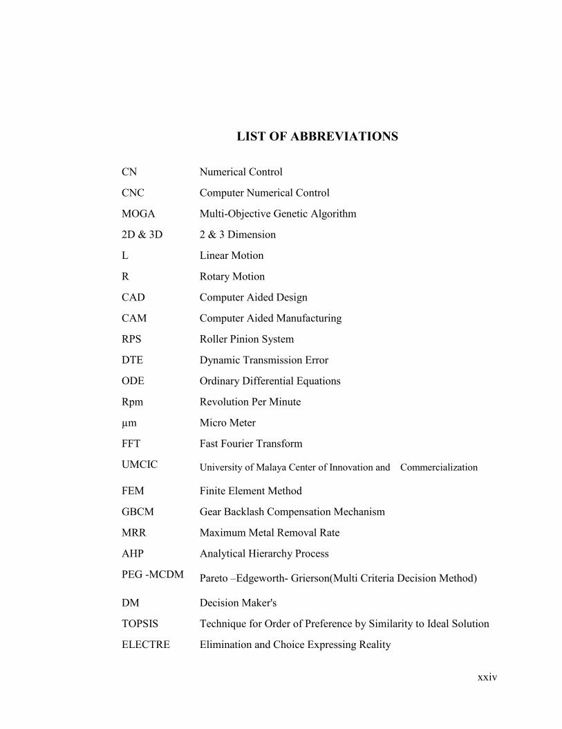
CN Numerical Control
CNC Computer Numerical Control
MOGA Multi-Objective Genetic Algorithm
2D & 3D 2 & 3 Dimension
L Linear Motion
R Rotary Motion
CAD Computer Aided Design
CAM Computer Aided Manufacturing
RPS Roller Pinion System
DTE Dynamic Transmission Error
ODE Ordinary Differential Equations
Rpm Revolution Per Minute
µm Micro Meter
FFT Fast Fourier Transform
UMCIC University of Malaya Center of Innovation and Commercialization
FEM Finite Element Method
GBCM Gear Backlash Compensation Mechanism
MRR Maximum Metal Removal Rate
AHP Analytical Hierarchy Process
PEG -MCDM Pareto –Edgeworth- Grierson(Multi Criteria Decision Method)
DM Decision Maker's
TOPSIS Technique for Order of Preference by Similarity to Ideal Solution
ELECTRE Elimination and Choice Expressing Reality
LIST OF ABBREVIATIONS

xxv
GRA Generic Risk Assessment
C.I Consistency Index
C.R. Consistency Ratio
MSE Calculating Mean-Square-Error
Eq. Equation
TPM Technology Park Malaysia
EMA Experimental Modal Analysis

xxvi
Kg Kilogram
mm Millimeter
g Gram
N Newton
HZ Hertz
kPa Kilopascal
Momentum
F Force
V Velocity
P Presser
ms Millisecond
KHz Kilo Hertz
m/s Meter per Second
MP a. Mega Pascal
jt, Circular Backlash
jt, Normal Backlash
jr Center Backlash
jθ Angular Backlash
ft/sec Feet per Second
GPa Giga Pascal
N.F. Natural Frequency
LIST OF SYMBOLS
1
1.1 General Background
Machine tools are spatial mechanisms with several degrees of freedom and require suf-
ficient workspace to coordinate workpiece and tool movement for the machining operation
(Reuleaux., 2007). The function of these machines is to move either the tool or the
workpiece, or both at the same time (simultaneously) for machining.
During the industrial development, John T. Parsons invented the first numerical control
(NC) machine around 1950 (Arnold, 2001; IOS, 2001). This NC machine had some prob-
lems. Although it worked automatically and produced workpieces with a high degree of
accuracy, it was complicated and expensive (Sematech, 1997). The first generation of nu-
merical control was this NC machine introduced in 1950, which was developed for CNC
machines after a few years. CNC technology has a radical effect on manufacturing expan-
sion across the globe (Newmana, 2008 ). This technology offers the advantage of produc-
ing a huge array of complex, different size components, from micro- to multi-meters, as
well as various types of materials such as aluminum and titanium alloys (Newmana, 2008 ).
Between the 1970s and 1980s, for producing more complex components, CNC machine
manufacturers felt the CNC machine needed to have additional axes for wider usage and
flexibility (Xu, 2006). Moreover, a high-accuracy CNC milling machine was required for
many industrial purposes due to the growing demand for component precision and con-
sistency of quality. However, for industrial requirements, CNC machine makers added ex-
tra axes consecutively. After the three-axis CNC machine, five-axis CNC machine tools
CHAPTER 1
1 INTRODUCTION

2
became increasingly popular owing to their ability to efficiently machine free-form surfac-
es (Lei, 2007). Five-axis CNC machines have most widely been used in machining com-
plex surfaces. Five motions are simultaneously and continuously controlled with a five-axis
machine. This machining ability can be useful in different, complex machining processes.
The three-axis CNC machine is complemented by two additional rotary axes to adjust the
tool orientation relative to the workpiece. The benefits of the five-axis CNC machine in-
clude: better tool accessibility, high material removal rate (MRR), surface quality, less
workpiece setup time and significantly lower production costs (W.T. Lei, 2002). One of the
important applications of the five-axis CNC machine is in industrial die and molds; this
machine tool has been widely used to machine complex parts in this field. Five-axis CNC
machines are not only applicable in milling operations but can be general-purpose, such as
for boring, turning and grinding (Teo, 2007).
1.2 Importance of Study
Five-axis CNC machine applications are crucial to the development of nearly all indus-
trial fields. Industrialized countries aim to have CNC five-axis machine technologies be-
cause CNC production is profitable. Nowadays, five-axis CNC machines yield huge profits
worldwide and their price is rising. Nonetheless, five-axis CNC machine technology is very
complicated and is rapidly undergoing development.
There are two ways to obtain this technology: reverse engineering or reverse design. The
reverse engineering method is a famous means of producing many things, but it is not ad-
dressed in this thesis. CNC gantry machine design has been considered for achieving the
technology. The importance of this study lies not only in the design of a CNC gantry ma-

3
chine but also in significantly improving the specifications of existing CNC gantry ma-
chines.
Some of the main goals are to improve precision while reducing size and cost and en-
hancing abilities. Small machine size and particular specifications are required to obtain
results. Therefore, this research provides the design of a new CNC gantry for industrial
purposes. New specifications are considered in designing a five-axis CNC gantry machine
with a double motion mechanism and high speed machining as some of this machine’s
characteristics.
1.3 Research Problem Statement
Designing five-axis CNC machines is challenging due to the technical complexity. De-
sign information of existing machines is not readily available, nor is it completely found in
books. Nevertheless, the required knowledge must be found, which will take a long time.
Unfortunately, machine manufacturers do not disclose the main CNC gantry machine tech-
nology knowledge and seldom can this science be found in papers or books. A number of
problems are evident in the first type of existing CNC gantry machine, such as machine
worktable length, precision and industrial space length. These must be solved by improve-
ments through our proposed gantry machine, which is the main target. Therefore, a new
five-axis CNC gantry machine design is required to solve the problems with the specifica-
tions, so a fundamental redesign of the machine is essential. This research is an attempt to
solve these problems in this study by designing a new CNC gantry machine. The process of
understanding and solving design problems is part of the difficulty with this technology.

4
1.4 Study Objectives
In this work, a novel type of CNC gantry machine will be designed. There are two main
objectives:
i. Design a new type of CNC gantry machine with a double motion feed drive
system (for moving both the gantry and table simultaneously). The design
includes details of the machine structure, gantry, worktable, carriages and
components, besides selecting suitable standard components.
ii. Prototyping of a semi-industrial size of new type of the CNC gantry ma-
chine which complies with standard components.

5
1.5 Research Methodology Flowchart
The flowchart of the research activities is shown in Figure 1.1.
Figure 1.1 Study Flowchart
Understanding the concept
Literature Review
Innovative Idea of a CNC Gantry Patent
Verification
Design Optimization
Documentation
Final Machine Assembly
Primary Design
Fundamental Design
Modification
Design Selection process
Prototyping the Machine
Experimental Test for Verification
Writing the Thesis
Patent
Patent
3-Design Verification
1-Identifying The problems
2-Design steps
4- Design Modification
5- Manufacturing Process

6
1.6 Research Activity Explanation
i. Understanding the Concept
The objective of this work is to design a new type of CNC gantry machine with high-
performance features. The performance of existing CNC gantry machine types can be en-
hanced. In fact, the feed drive motion of the new machine is totally different from existing
types. The gantry and table can move together simultaneously in this design. For a briefing
of the main concept, current types of CNC gantry machine must be explained.
ii. Literature Review
The literature review of prior experience about CNC gantry machine design based on
available resources (e.g., the Internet, journals and conference proceedings) can help
achieve the desired goal. The main objective of this study is to identify the capabilities of
each machine type, such as structures, motion mechanisms and applications to designing
new types. Therefore, the researcher must investigate the main different types of existing
CNC gantry machine to conceive the new idea of developing them.
iii. Innovative Idea of a CNC Gantry Machine
The new idea of a CNC gantry machine based on the conceptual design is presented.
This type of machine is made to further develop the CNC gantry machine.
iv. Patent Process
All documents related to the design novelty are prepared and submitted to the UMCIC
section for patenting.

7
v. Primary Design Step
The primary design of the new type of CNC gantry machine from the conceptual design
is discussed in this section. The overall machine design is considered.
vi. Fundamental Design Steps
The fundamental design of a CNC gantry machine with a double motion mechanism
from the primary design is considered and discussed. The different machine designs are
presented and compared in this section to find the best design of a new gantry machine
based on certain requirements.
vii. Analysis Process
Design verification via modal, harmonic and static analysis methods are considered,
and the result is applied for further machine modification.
viii. Modification Process
The design target is for the machine to be capable of tolerating around 200 Hz of natural
frequency in the first mode of vibration. Therefore, a gantry modification process is per-
formed. In this process, the modified design will be compared with the final modification
results to find a solution to increase performance, such as design dynamics and static be-
havior.
ix. Design Selection Process
In this section, several gantry designs will be selected for performance comparisons.
Some gantry specifications include the natural frequencies of the first of four modes, total
deformation of the gantry under working forces, gantry weight and manufacturing costs.
The optimum design will be presented through special optimization methods.

8
x. Optimization Process
The selected design will be optimized with MOGA (multi-objective genetic algorithm)
via ANSYS software. In this process, gantry performance will be investigated. Some gantry
technical specifications must be maximized while others must be minimized. Optimized
design documents will also be prepared for the fabrication process.
xi. Documentation
All design documents required for manufacturing are prepared and presented in this sec-
tion. 3D and 2D documents for making patterns, casting, machining and assembly are
made.
xii. Manufacturing Process
The prototyping steps for a new CNC gantry machine are presented in this section. A
concise report about the processes of pattern making, casting, machining and assembly of
the new CNC gantry machine will be presented and discussed. The manufactured detail
components and purchased standard components of the machine have been shown in Ap-
pendix (A and F).
xiii. Experimental Test for Verification
Following gantry prototyping, to verify the design process an experimental analysis test
will be performed on the prototyped gantry using related instruments. The differences be-
tween experiment results and design analyses are investigated.
xiv. Final Machine Assembly
All fabricated machine components will be assembled in this section.

9
1.7 Scope of Work
The main objective of this project is to design and manufacture a new type of CNC gan-
try machine, with the aim of solving the problems of existing CNC gantry machines by cre-
ating a new design in this project. The main advantages of the new design are presented
below.
i. Increase Worktable Length
In the first type of gantry machine the worktable length is limited to the length of the
ball screw. Using a double motion mechanism for feed drive motion should solve the prob-
lem.
ii. Decrease the Total Length of the Machine
The total length of the existing type of gantry machine is nearly twice that of the work-
table and in the new design it is reduced to almost one and a half times the worktable.
iii. Improve Total Precision of the Machine
In the current type of gantry machine the total precision is dependent on the total length
of the ball screw. In the new design a shorter ball screw is used, hence machine precision is
increased.
iv. Increase Machining Rapid Speed
The X-axis rapid speed in the existing type of gantry machine is dependent on the work-
table or gantry speed. In the new design, the rapid speed is increased to the total speed of
the worktable and gantry.

10
v. Considerably Increase Machine Efficiency
In the new CNC gantry machine design, the total efficiency will be increased on account
of the double motion mechanism.
vi. Simplify Machine Manufacturing
In the new CNC gantry machine design, the total machine length will be decreased sig-
nificantly to simplify the manufacturing process.
vii. Significantly Decrease the Total Cost of the Machine
With the new CNC gantry machine design, the total manufacturing cost will be de-
creased due to simplifying the process.
1.8 Organization of the Thesis
This research is divided into seven chapters.
CHAPTER 1: INTRODUCTION
Chapter one presents a general background and the importance of the study, the research
problem, statement of study objectives, research methodology, an explanation of research
activities, scope of study, the concept and how the contents are organized.
CHPTER 2: LITERATURE REVIEW
Chapter two comprises an introduction, a general background of machine tool design,
machine kinematic chain design, common configurations of a five-axis machine, CNC gan-
try machine types and accessories, machine structure, design-related key words for a CNC
machine gantry, such as modification, optimization, feed drive, anti-backlash with a new
anti-backlash system proposed and the conclusion.
11
CHAPTER 3: CONCEPTUAL DESIGN OF A NEW GANTRY MACHINE
Chapter three includes an introduction and the conceptual design of a new type of CNC
gantry machine. The advantages of the new type are explained, a CNC gantry machine feed
drive motion is proposed and a feed drive design (double motion mechanism) based on rack
and pinion is proposed. The design of a new CNC gantry based on a double motion mecha-
nism is presented and then the characteristics of the double motion mechanism and its prob-
lems are investigated. A new anti-backlash mechanism with a new idea for solving the first
problem of the double motion mechanism is proposed and a new anti-backlash (GBCM)
mechanism is designed. Subsequently, three new CNC gantry machine designs based on
the new anti-backlash are proposed. Nonlinear dynamic analysis of the new anti-backlash
gear mechanism design for less dynamic transmission error is carried out and the nonlinear
dynamic model is discussed. The chapter ends with a conclusion.
CHAPTER 4: STRUCTURAL DESIGN OF A GANTRY MACHINE TOOL
Following the introduction, chapter four presents the design of a double motion mecha-
nism based on a ball screw system. The double motion mechanism and its modified charac-
teristics are discussed. The gradual design of the new type of CNC gantry machine is pro-
posed based on the new motion system. The third CNC gantry machine design process is
described and analyzed. Further modification is done based on dynamic and static results
and the behavior of the modified gantry under cutting force and natural frequency below
12000 RPM is evaluated. The fourth design is introduced and a fifth gantry machine design
is proposed based on crossbeam modifications. The best gantry design is selected according
to the initial gantry design. The selection parameters are defined for the selection process
and finally, the chapter concludes.
12
CHAPTER 5: OPTIMUM SELECTION SEEKING USING MULTI-CRITERIA DE-
SIGN MAKING (MCDM) AND MULTI-OBJECTIVE STRUCTURAL OPTIMIZATION
OF A GANTRY
Chapter five begins with an introduction and continues with seeking the optimum design
using AHP and PEG-MCDM. The optimization objectives are investigated, the optimiza-
tion methods and gantry parameters for the optimization process are evaluated and the sen-
sitivity of the gantry parameters is assessed as well. Gantry optimization is carried out
based on the MOGA method and the chapter finishes with conclusions.
CHAPTER 6: GANTRY MACHINE MANUFACTURING PROCESS AND TESTING
Chapter six starts with an introduction, which is followed by the design preparation of
the new CNC gantry machine documents. The machine fabrication technology and its ma-
terials will be investigated and the experimental result of vibration of the gantry will be
prepared. In addition the final assembly process of the CNC gantry machine will be dis-
cussed. Finally the CNC controller of the machine will be introduced.
CAPTER 7: THESIS CONCLUSION
Chapter seven comprises the thesis conclusions, directions for future research, future
works and recommendations.
13
2.1 Introduction
Machine tools have an important role in manufacturing and have undergone considera-
ble productivity, precision and durability in the past few decades. The requirements for the
operational and technological properties of materials employed have also increased signifi-
cantly (Shevchuk, 2008). Surface roughness is a major consideration in modern Computer
Numerical Control (CNC) machines (Lan, 2010). It is desirable that the negative effects
such as vibration and noise in the machine tools used today be brought to a minimum. De-
sired machine tool properties include high static stiffness for bending and torsion, good dy-
namic characteristics, good dimensional stability, low coefficient of expansion, low cost
and low material requirements (Rahman, 2001.Bazul,).
In this thesis, designing a “new type” of gantry machine tool is accomplished using sev-
eral concept and methods. Static and dynamic machine tool characteristics affect the final
attainable accuracy and therefore, relevant literature is investigated in this chapter. In addi-
tion to static and dynamic characteristics, the cost of production and weight are considera-
ble matters in designing machine tools. To attain optimal results, optimization and decision
making methods could be exploited. Such methods provide scientific procedures for obtain-
ing the optimal design and at the same time reduce the time invested in the design stage.
Accordingly, relevant research regarding optimization and multi-criteria decision making is
investigated.
CHPTER 2
2 LITERATURE REVIEW

14
2.2 Concepts of Machine Tool and Gantry Machine Tool Technology
A machine tool is a special device capable of cutting away surplus material from a
workpiece in accordance to the specimen’s shape and size, as well as required degree of
accuracy and surface finish. The machine tool should meet these requirements and must be
able to uphold the cutting tool and workpiece provide sufficient power to enable the tool to
cut the material from the workpiece and position the tool and workpiece relative to each
other. The positioning must be controlled with a certain degree of accuracy. There are
many categories of machine tools, such as turning, milling and so on, with gantry machine
tools belonging to the milling category.
2.2.1 General Background of Milling Machine Tool Design
Lopez de Lacalle, Bohez and their colleagues are recognized for advancing the design
procedure of CNC milling machines. Therefore, it is necessary to become familiar with
their basic notions about machine kinematics and the definition of machine axis motion
(Bohez, 2002; Lamikiz, 2009).
Generally, the main specifications of a milling machine tool must satisfy the following
principles(Bohez, 2002; Lamikiz, 2009):
- The machine kinematics should provide sufficient flexibility for the orientation
and positioning of the tool and workpiece.
- Orientation and positioning must be accomplished with the highest possible
speed and accuracy.
- The tools and workpiece must be furnished for the fastest potential change.

15
- The machine cutting tool must be designed with the highest possible material
removal rate (MRR).
Mainly, the number of axes of a milling machine tool or the number of independent con-
trollable motions of movable parts is defined in terms of degrees of freedom. ISO 84/2001
recommends following the right-hand rule for defining the nomenclature of an axis coordi-
nate system to the corresponding Z-axis (tool axis). Hence, a three-axis milling machine
has three linear motions for the main parts (X-, Y- and Z-axis), which can be positioned
anywhere within a particular range that is limited by an over-travel limit switch. In a three-
axis CNC machine, the tool’s direction will be fixed during the machining process. Accord-
ing to this limitation, the flexibility of the tool orientation will be related to the workpiece,
therefore several different setups will be needed for machining (Lamikiz, 2009). To de-
crease the number of setups, more degrees of freedom must be added to the machine’s axes
to increase tool flexibility and workpiece orientation. For this purpose, rotational-
movement axes can be added to conventional three-linear axis machines to obtain more
flexibility in the machining process. A manual five-axis machine is a mechanical five-axis
milling machine, which can use a rotary tool with five degrees of freedom that can move in
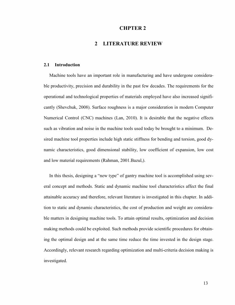
any workspace orientation and position. Figure 2.1 represents a DMG 60 U five-axis man-
ual milling machine.
2.2.2 Milling Machine Kinematic Chain Diagram
The five-axis CNC milling machine is actually similar in structure to two robots
(Lamikiz, 2009), one of which is responsible for carrying the workpiece and the other the
tool. Bezier (Be´zier, 1972) and Held (Held, 1991) presented an introduction to five-axis
16
milling, machine applications and multi-axis machining regarding kinematics and axis ori-
entation.
Figure 2.1 : The “DMG 60 U” Five-axis Manual Milling Machine (Lamikiz, 2009)
They explained that for orienting two rigid bodies in space relative to each other, six de-
grees of freedom are required for each body (tool and workpiece). Hence, twelve degrees of
freedom are needed for the orientation altogether. However, six degrees of freedom can be
reduced in number rather than each relative common orientation. For sufficient flexibility
orientation between tool and workpiece, at least five degrees of freedom are
required(Bohez, 2002), meaning that the tool and workpiece can be oriented relative to
each other under any angle via five degrees of freedom.
According to the kinematic (chain) diagram, two axis groups are prevalent. In milling
machine tools some axes are responsible for carrying the tool and others the

17
workpiece(Bohez, 2002). Hence they can be divided into workpiece axis carriers and tool
axis carriers. Furthermore, (L) and (R) introduce the axes, where L means a linear axis and
R a rotational axis. Figure 2.2 presents the milling machine’s kinematic configuration as
(RRLLL), meaning the workpiece is carried by four axes (RRLL) and the tool only by one
axis (L) (Bohez, 2002; Lamikiz, 2009). In Figure 2.2, according to the kinematic chain de-
sign, the first axis of the classical five-axis milling machine usually defines other axes.
However, the best kinematic design is the one in which the workpiece is carried by just one
axis of freedom and the other axes carry the tool.
Figure 2.2 : Kinematic Configuration (RRLLL)(Bohez, 2002)
2.2.3 Common Five-axis Machine Configurations
Based on the kinematic chain in a five-axis milling machine, there are three common
configurations starting from the workpiece and moving towards the tool tip (Lamikiz,
2009) as follows.

18
2.2.3.1 RRLLL Configuration
This configuration is normally applied in small, compact machines (Lamikiz, 2009).
The table (workpiece) is supported by a double rotation (RR) table, pendulous and rotation-
al simultaneously. One is a swiveling motion and the other is a rotation around the axis
perpendicular to the plate and three linear axes provided by the tool. Figure 2.3 shows the
RRLLL configuration.
Figure 2.3 : RRLLL Configuration (Lamikiz, 2009)
2.2.3.2 RLLLR Configuration
This five-axis machine configuration is very suitable for tall and cylindrical workpieces
)Díaz, 2009; L.N, 2009(. The table (workpiece) is supported by a rotary turning table (R) as
well as Y-axis motion (L). Two other axes (X and Z) have linear motion (LL) and the head-
stock provides swiveling (R) of freedom. Figure 2.4 illustrates the RLLLR configuration.
This configuration is used for machining large gantry machine tools, usually big industrial
molds and dies (Díaz, 2009; L.N, 2009). Three linear motions (LLL) by the X-, Y-, Z-axis
whose Cartesian motions are produced either via the tool axes or machine table

19
(workpiece) and two rotary motions (RR) by the headstock and spindle are produced Fig-
ure 2.5 shows the LLLRR configuration. The different types of CNC gantry machine tools
will be discussed next.
Figure 2.4 : RLLLR Configuration (Lamikiz, 2009)
Figure 2.5: LLLRR Configuration (Lamikiz, 2009)
2.3 Types of CNC gantry machine tool
There are different milling machine structure categories, such as the C-frame gantry
frame. CNC gantry machines can be used for making large workpieces. Gantry machine
tools are widely applied for machining complex components in the industrial field (B.

20
Sencer, 2008). For instance, in recent years, CNC machine center and gantry milling ma-
chines are the indispensable processing equipment for energy, aerospace, shipbuilding, au-
tomobile, railway and engineering machinery and tools.
The general configuration of these machines is LLLRR. Three linear motions, namely
X-axis via worktable or gantry, Y and Z-axis carriages and two rotational motions via a ro-
tary headstock, which is a CNC machine accessory, make the chain kinematic configura-
tion of CNC gantry machines. Among several accessories for CNC gantry machines are the
rotary headstock, automatic tool changer (ATC) and automatic pallet changer (APC). These
accessories are used for easy machining and easy tool and component changing in the man-
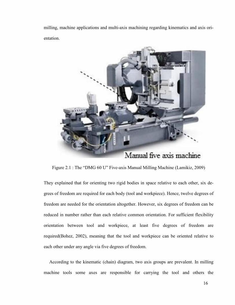
ufacturing process. The rotary headstock is one of most important accessories of a five-axis
CNC gantry machine. Figure 2.6 shows a classic example of a rotary headstock, the “twist
and swivel head.” The twist head facilitates greater accessibility and positioning to tradi-
tional 3-axis machines. However, this head does not have high stiffness, so in terms of ac-
curacy and dynamics it is not suitable for high power applications. Over the last few years,
the traditional gear transmission for two rotational axes has been replaced by a torque mo-
tor (L.N, 2009). The torque motor is directly inserted into the rotary joints. Eliminating the
gears leads to stiffness enhancement, avoiding backlash and more precise rotation.
Torque motors are mainly designed for low speed applications. Their combined ad-
vantages are performance, high torque levels, high dynamic response (due to small electri-
cal time constants), high efficiency (due to permanent magnets), high angular rotation and
dynamic stiffness. Prior to designing a new type of gantry, it is essential to familiarize with
different available types and their condition. At the moment, there are two types of gantry
machine in the world (Tsann-Huei Chang, 2004). In the first type, the gantry is fixed and
21
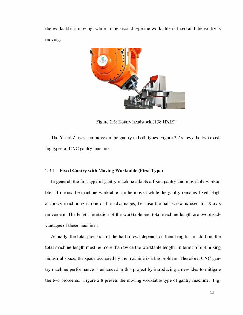
the worktable is moving, while in the second type the worktable is fixed and the gantry is
moving.
Figure 2.6: Rotary headstock (158 JIXIE)
The Y and Z axes can move on the gantry in both types. Figure 2.7 shows the two exist-
ing types of CNC gantry machine.
2.3.1 Fixed Gantry with Moving Worktable (First Type)
In general, the first type of gantry machine adopts a fixed gantry and moveable workta-
ble. It means the machine worktable can be moved while the gantry remains fixed. High
accuracy machining is one of the advantages, because the ball screw is used for X-axis
movement. The length limitation of the worktable and total machine length are two disad-
vantages of these machines.
Actually, the total precision of the ball screws depends on their length. In addition, the
total machine length must be more than twice the worktable length. In terms of optimizing
industrial space, the space occupied by the machine is a big problem. Therefore, CNC gan-
try machine performance is enhanced in this project by introducing a new idea to mitigate
the two problems. Figure 2.8 presets the moving worktable type of gantry machine. Fig-

22
ure 2.9 presents a moving table type gantry machine with working space length twice the
table length.
(a) Fixed Gantry
(b) Fixed Table (integrated
gantry)
(c) Fixed Table (disintegrate gantry)
Figure 2.7 : The Two Types of CNC Gantry Machine
(a) Fixed Gantry
(a) Fixed Gantry
Figure 2.8: Moving worktable and fixed gantry (Macrotec Machine tools LTD)
Figure 2.9: Working Space of the First Type of Gantry Machine (Macrotec Machine
tools LTD)
23
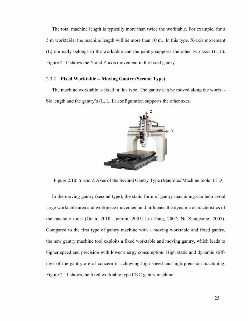
The total machine length is typically more than twice the worktable. For example, for a
5 m worktable, the machine length will be more than 10 m. In this type, X-axis movement
(L) normally belongs to the worktable and the gantry supports the other two axes (L, L).
Figure 2.10 shows the Y and Z-axis movement in the fixed gantry.
2.3.2 Fixed Worktable -- Moving Gantry (Second Type)
The machine worktable is fixed in this type. The gantry can be moved along the workta-
ble length and the gantry’s (L, L, L) configuration supports the other axes.
Figure 2.10: Y and Z Axes of the Second Gantry Type (Macrotec Machine tools LTD)
In the moving gantry (second type), the static form of gantry machining can help avoid
large worktable area and workpiece movement and influence the dynamic characteristics of
the machine tools (Guan, 2010; Jianrun, 2005; Liu Fang, 2007; Ni Xiangyang, 2005).
Compared to the first type of gantry machine with a moving worktable and fixed gantry,
the new gantry machine tool exploits a fixed worktable and moving gantry, which leads to
higher speed and precision with lower energy consumption. High static and dynamic stiff-
ness of the gantry are of concern in achieving high speed and high precision machining.
Figure 2.11 shows the fixed worktable type CNC gantry machine.
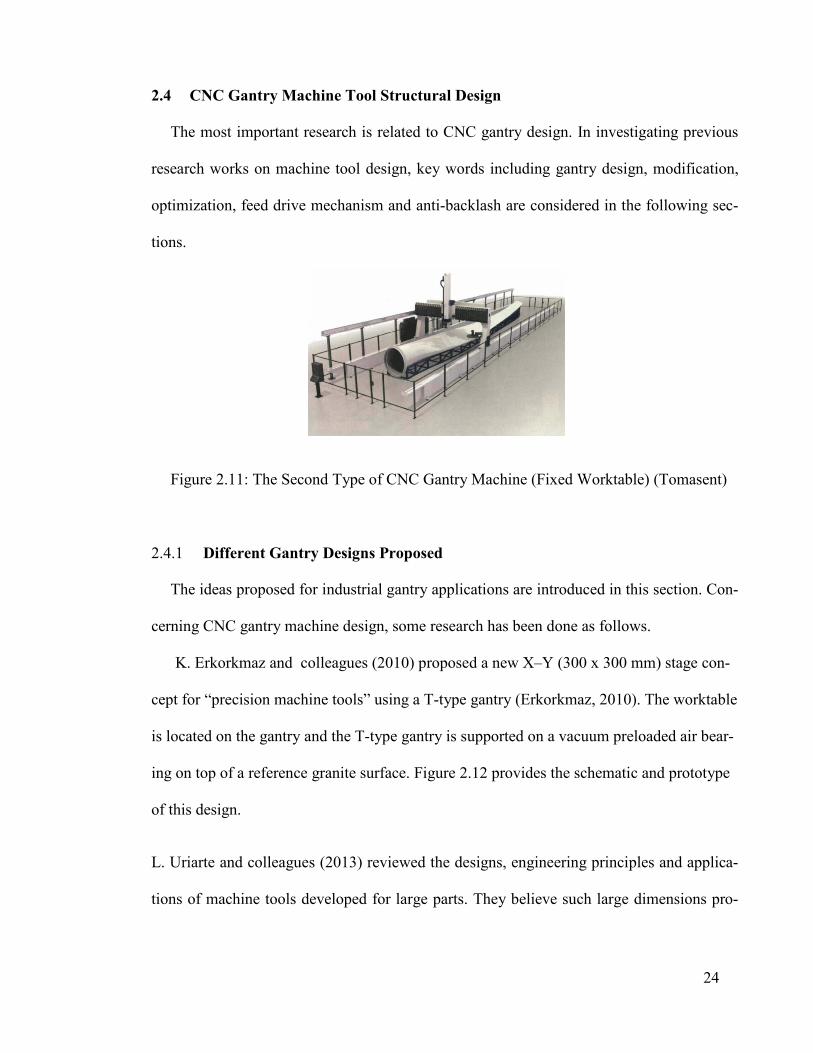
24
2.4 CNC Gantry Machine Tool Structural Design
The most important research is related to CNC gantry design. In investigating previous
research works on machine tool design, key words including gantry design, modification,
optimization, feed drive mechanism and anti-backlash are considered in the following sec-
tions.
Figure 2.11: The Second Type of CNC Gantry Machine (Fixed Worktable) (Tomasent)
2.4.1 Different Gantry Designs Proposed
The ideas proposed for industrial gantry applications are introduced in this section. Con-
cerning CNC gantry machine design, some research has been done as follows.
K. Erkorkmaz and colleagues (2010) proposed a new X–Y (300 x 300 mm) stage con-
cept for “precision machine tools” using a T-type gantry (Erkorkmaz, 2010). The worktable
is located on the gantry and the T-type gantry is supported on a vacuum preloaded air bear-
ing on top of a reference granite surface. Figure 2.12 provides the schematic and prototype
of this design.
L. Uriarte and colleagues (2013) reviewed the designs, engineering principles and applica-
tions of machine tools developed for large parts. They believe such large dimensions pro-
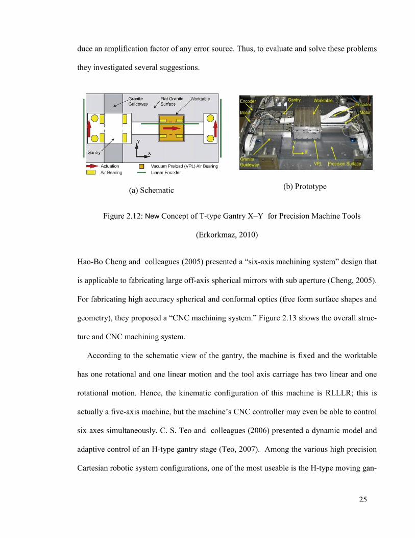
25
duce an amplification factor of any error source. Thus, to evaluate and solve these problems
they investigated several suggestions.
(a) Schematic
(b) Prototype
Figure 2.12: New Concept of T-type Gantry X–Y for Precision Machine Tools
(Erkorkmaz, 2010)
Hao-Bo Cheng and colleagues (2005) presented a “six-axis machining system” design that
is applicable to fabricating large off-axis spherical mirrors with sub aperture (Cheng, 2005).
For fabricating high accuracy spherical and conformal optics (free form surface shapes and
geometry), they proposed a “CNC machining system.” Figure 2.13 shows the overall struc-
ture and CNC machining system.
According to the schematic view of the gantry, the machine is fixed and the worktable
has one rotational and one linear motion and the tool axis carriage has two linear and one
rotational motion. Hence, the kinematic configuration of this machine is RLLLR; this is
actually a five-axis machine, but the machine’s CNC controller may even be able to control
six axes simultaneously. C. S. Teo and colleagues (2006) presented a dynamic model and
adaptive control of an H-type gantry stage (Teo, 2007). Among the various high precision
Cartesian robotic system configurations, one of the most useable is the H-type moving gan-
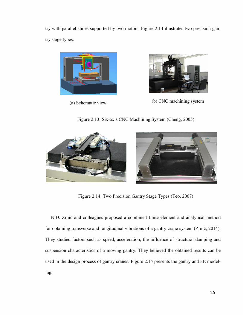
26
try with parallel slides supported by two motors. Figure 2.14 illustrates two precision gan-
try stage types.
(a) Schematic view
(b) CNC machining system
Figure 2.13: Six-axis CNC Machining System (Cheng, 2005)
Figure 2.14: Two Precision Gantry Stage Types (Teo, 2007)
N.Đ. Zrnić and colleagues proposed a combined finite element and analytical method
for obtaining transverse and longitudinal vibrations of a gantry crane system (Zrnić, 2014).
They studied factors such as speed, acceleration, the influence of structural damping and
suspension characteristics of a moving gantry. They believed the obtained results can be
used in the design process of gantry cranes. Figure 2.15 presents the gantry and FE model-
ing.

27
Figure 2.15: (a) Gantry Crane, (b) FE Model of the Gantry and (c) Moving System
Ling Zhao and colleagues (2011) proposed a method to design lightweight and high ef-
ficiency large gantries by introducing a natural bionic structure (Zhao, 2011). They made a
laboratory model to test it and a number of gantry performances, such as natural frequency
and improved weight.
Figure 2.16 shows the idea and testing of the lightweight gantry design.
Giant water lily leaf and its vein distribution
(a) The conventional ribs of original model (b) Improved bionic model
Setup for the static test
Figure 2.16: The Idea and Laboratory Static Testing of a Lightweight Gantry (Zhao, 2011)

28
2.4.2 Gantry Design Modification
Highly accurate CNC machine tools are also needed due to the growing demand for pre-
cision and consistent quality machining. The geometry of CNC gantry machines has nor-
mally been designed for easy machining of long and high components. However, the rigidi-
ty of the machine’s gantry gets reduced under severe load during machining operations.
Thus, vibration or deformation will occur during machining. After designing a gantry,
some of its characteristics are often not satisfactory and depending on the target, the design
must be modified. Manufacturers attempt to modify designs in order to achieve the strong-
est machine gantry for stability in the machining process because vibration negatively af-
fects product quality. The first natural frequencies of previous gantry designs are seldom
higher than 100 Hz (Ming, 2010; Shubo Xu, 2010). But for high finishing processes, ma-
chine tools are required to reach more than 8000 rpm. Therefore, the minimum natural fre-
quency of a machine’s gantry must be higher than 140 Hz. For the finishing process, a high
speed spindle is normally needed. Milling machines with less than 150 Hz natural frequen-
cy are not capable of high speed machining, so lower quality surface is used. Hence, the
design of a CNC machine gantry with rapid machining ability requires an appropriate gan-
try. Some researchers have explored gantry performance modification methods that can
sustain vibration during high speed machining. Several software tools are available for gan-
try modification purposes and will be discussed next.
2.4.2.1 Computer-Aided Design (CAD) software for designing and drawing
The comprehensive CAD (computer-aided design) application for different industrial
purposes yields enhanced modification methods. Recently, design and modification pro-
cesses done via CAD systems have covered all designer requirements according to re-
29
quests. Numerous researchers have tried to develop the CAD application software for in-
dustrial purposes. Lin and colleagues have attempted this and described a newly developed
algorithm for CAD using coordinate measuring machines (CMMs) (Lin, 2001). Many dif-
ferent CAD software types have been produced to help with designing and modifying a
subject.
2.4.2.2 Computer-aided analysis via FEM software (dynamic and static)
High static and dynamic stiffness are typically required when the gantry is moving. It is
difficult to predict the static and dynamic behavior of a gantry by traditional methods
(Dhupia, 2007; Lee, 2006; Ra Jeev S, 2003; S. Haranath, 1987; Stamper, 1997). Therefore,
novel ideas must be applied to the design of gantry machine tools as well as the modifica-
tion process to improve gantry characteristics. The following is a summary of research fo-
cusing on modification via FEM (finite element method) for rapid improvement of machine
tool performance.
C. Yongqing performed finite element analysis of a structure for a 2400t gantry with
ANSYS software and obtained the stress and deformation of key components in a variety
of conditions (C.Yongqing, Jan. 2007). Z. Dewen accurately calculated the arch degrees of
bridge type crane girders based on FEM. This method facilitated all sorts of deflection cal-
culation means for bridge type crane girders and deduced the calculation formula of webs
baiting arch degrees curve before the girder was made (Z.Dewen, 2006). F. Junlian applied
a modification program to modify the main girder and proposed a research method for
bridge crane girder structure analysis and optimal design (FJunlian., 2006). S. V. Sorokin
analyzed and optimized the energy flow of a structure comprising a crossbeam element
30
(Sorokin, 2001). K. M. Khuberyan analyzed underground farm arched tents supported by
crane crossbeams and the analysis showed that the deformation and stress conditions of the
arch-supported wall affected the overall structure analysis results, so the impact of the sup-
ported wall should be added to the analysis (Khuberyan, 1972). Large span crossbeams are
complex, so it is difficult to experimentally obtain a range of parameters; therefore, accord-
ing to the structure’s characteristics, Guhua (Han, 2011) analyzed and modified the cross-
beam of a heavy NC machine moving gantry and milling machine. It had a certain refer-
ence value to the design and analysis of large span machines.
2.4.3 Structural Optimization of a Machine Tool
Gantry machine tools with the advantage of extensive machining span, high machining
precision and good rigidity have been broadly applied in manufacturing industries and sub-
sequently, their development has been rapid. In China, major scientific and technological
projects of “high-grade CNC machine tools and basic manufacturing equipment” with gan-
try machine tool R&D have been undertaken as an important study issue. Focus is on struc-
tural dynamic optimization design techniques for the gantry machine tool’s main compo-
nents and parts. An important part of a gantry machine tool, the crossbeam achieves Y-axis
feed motion and supports the spindle system to achieve Z-axis feed motion. The cross-
beam’s structural and dynamic properties directly affect the gantry machine tool’s overall
stiffness and machining precision. Therefore, the crossbeam’s structural optimization de-
sign for the gantry machine tool has become a research focus of more and more scholars.
Luo and Li (2006) analyzed the stiffness of a crossbeam with different rib plate shapes by
finite element method (Luo, 2006). Shi (2009) conducted static, modal and harmonic anal-
yses for the gantry machine centre’s crossbeam and identified the weakness for further op-

31
timization design(Liu Fang, 2007) . Wang et al. (2009) conducted topology optimization
for the crossbeam by studying the layout of the rib plates, so the static stiffness and anti-
vibration performance were greatly improved (Wang XY, 2009). Guan et al. (2010) dis-
covered the weak link in a gantry machine tool’s crossbeam by using FEM and put forward
a modification scheme, which enhanced the crossbeam’s static and dynamic performance
(Guan, 2010). Zhao et al. (2008) carried out structural bionic optimization for the stiffener
plate of a gantry machine tool’s crossbeam based on giant waterlily vein distribution, so the
crossbeam achieved a lightweight performance design and its dynamic performance was
further improved (Zhao, 2008).
Currently, the optimization of structural components for machine tool design is usually
done through the static and dynamic stiffness as well as the structure’s natural frequency as
the optimized objective function. The majority of researchers have employed the finite el-
ement method (FEM) to optimize the main structural components of machine tools and also
scientifically analyzed flutter during machining. In the US, Vance from Iowa State Univer-
sity and Yeh from the IsU Research Center optimized the design of a machine’s structural
shape by virtual reality technologies (Gimenez, 1995). Jiang and Chiredast from Michigan
University presented a math model to simulate a joint form of the machine tool structure,
set up a whole machine model and then did topology optimization on the locations and
quantities of connecting pieces (e.g. solder joints, bolts) between the machine’s bonding
surfaces (Liu, 1995; Liu Fang, 2007) .
Gantry optimization is the process of altering parameters to obtain the best results under
given conditions. In the steps of the design process or updating any engineering system,
engineers are faced with many important technological decisions. The final goal of such

32
decisions is to either minimize the effort required to maximize the desired benefit or vice
versa. A practical situation can express the required effort or desired benefit as a function
of certain decision variables. The optimization process can be defined as the conditions that
yield the maximum or minimum value of a function. There are several available optimiza-
tion methods for solving problems and a number of them have been developed to solve var-
ious types of problems (Krishna, 2009; Rao, 2009).
Mathematical programming techniques are useful to minimize or maximize a function of
several variables based on certain limitations. For analyzing the problems described by a
set of random variables, also known as probability distributions, stochastic process tech-
niques can be used. Statistical methods can be used to analyze experimental data and to
build practical models to obtain the most accurate representation of a physical situation
(Guang-Yuan, 1985; Majid, 1974).
As demand for high speed, high precision machining of large components rises, the gan-
try machine tool with the advantages of large machining span, high precision and high
speed, meets the demand of crucial industries, such as aerospace, military, ship building
and other large machine building industries. Due to the extensive application of these stra-
tegic gantry machine tools, many manufacturers invest in them to develop high speed, high
precision gantry machine tools, something that requires various developments in the design
stage of gantry machine tools.
Liu et al. (Liu, 2014) investigated the structural design of the gantry beam using multi-
criteria decision making with grey relational analysis and Analytical Hierarchy Process
(AHP). Design criteria include static, anti-vibration and lightweight performance. The op-
timal crossbeam design scheme was chosen among four initially proposed schemes. Six

33
optimal, non-inferior solutions based on the dynamic optimization of the selected scheme
were obtained. The final optimal solution was recovered using gray relational analysis. The
first four natural frequencies also increased around 17%.
The application of finite element software for modeling, optimizing and redesigning key
gantry machine components has been investigated by many researchers (Guan, 2010; Han,
2011; Weule, 2003; Xiuheng, 2010; Y. Guan, 2010; Yanhua, 2009; Zhao, 2011). Guan et
al. (Guan, 2010) proposed the finite element model of a GMCU2060 gantry machine cen-
ter. According to the FE model, static and dynamic stiffness of the crossbeam were ob-
tained. Based on analysis, weak points were discovered and through modification, the static
and dynamic stiffness was enhanced.
In another research conducted by Guan et al. (Y. Guan, 2010), the weak links of a five-
axis gantry milling machine were detected using modeling and analysis of key machine
tool components. Accordingly, the static stiffness increased to 68.4 /N m and the first
natural frequency increased from 30 Hz to 42 Hz with a mass reduction of 632 kg.
By applying the bionic approach inspired by giant waterlily leaf ribs and cactus stem
structure, Zhao et al. (Zhao, 2011) aimed to improve the structural characteristics of a Lin
MC6000 gantry machine center crossbeam. The results demonstrated the effectiveness of
the bionic approach with static deformation and weight reductions of 16.22% and 3.31%,
respectively and an increase in the first four natural frequencies.
Machine tool design often comprises many conflicting criteria, such as static, dynamic,
weigh and cost performance. Several multi-criteria decision making methods proposed in-
cluding AHP, ANP, TOPSIS, ELECTRE, PROMETHEE, GRA, PEG-MCDM (Grierson,

34
2008; Yanhua, 2009) have been successfully applied by numerous researchers in the design
stage (Ayağ, et al., 2011; Taha, 2012).
To date, most researches have intended to enhance the static and dynamic performance
of the gantry machine tool crossbeam, which results from the high rigidity of the gantry
machine’s fixed wall. However, in moving the gantry machine’s columns, the topology and
structural properties of the columns directly affect the ultimate machine performance.
Therefore, in this study, static, anti-vibration, light weight and low cost performance of the
gantry head consisting of a crossbeam and columns were investigated. Prior to optimiza-
tion, the AHP method, a well-known multi-criteria decision making method, was employed
for selecting the best design scheme proposed by gantry designer experts. Sensitivity analy-
sis was conducted prior to multi-objective optimization to discover influential parameters.
Using the design exploration toolbox of ANSYS Workbench, multi-objective optimization
of the selected gantry machine tool was achieved by applying the multi-objective genetic
algorithm (MOGA). In order to choose the ultimate design among non-inferior solutions
proposed by MOGA, the PEG-MCDM method was employed. To validate the simulation
results, experimental modal analysis was carried out on the gantry prototype by comparing
the first four natural frequencies obtained from simulation and experiments. The results
proved the effectiveness of the proposed design methodology for designing a gantry ma-
chine with high performance moving columns.
2.4.4 Applying Multi-Criteria Decision Making In the Machine Design
Multi-objective decision making (MODM) is aimed at optimal design problems in
which several (conflicting) objectives are to be achieved simultaneously. The characteris-
tics of MODM are a set of (conflicting) objectives and a set of well-defined constraints.

35
Therefore, MODM is naturally associated with a method of mathematical programming for
dealing with optimization problems. However, it is evident that two main difficulties in-
volving the trade-off and scale problems complicate the MODM problems through the
mathematical programming model.
In the trade-off problem, since a final optimal solution is usually obtained through math-
ematical programming, multiple objectives must transform it into a weighted single objec-
tive. Therefore, a process of obtaining trade-off information between the considered objec-
tives should first be identified. If the trade-off information is unavailable, Pareto solutions
should be derived. With the scaling problem, on the other hand, as the number of dimen-
sions increases beyond capacity, the curse of dimensionality problem arises, i.e., the com-
putational cost increases tremendously. Recently, many evolution algorithms, such as ge-
netic algorithms (Holland, 1975), genetic programming (Koza, 1992) and evolution strate-
gy (Rechenberg, 1973) have been suggested to handle this.
With the globalization of businesses, the competitive manufacturing companies must
invest and improve production facilities, especially regarding the introduction of new
equipment to the market. Therefore, machine tool selection for investing and improving
facilities is an important decision that plays on the survival of developing manufacturing
facilities. Improperly selected machines can negatively impact the overall system perfor-
mance, such as productivity, precision, flexibility, adaptation and responsiveness. As such,
this is a time-consuming and intractable problem and it is the largest drawback for engi-
neers and managers due to the lack of deep knowledge, experience and technological un-
derstanding (Budak, 2004; Ertuğrul, 2007).

36
The progress of the production economy always requires companies to find replacement
manufacturing solutions to respond to and satisfy customer demand. One of the significant
strategies to attain optimal operational performance is to apply production automation
through flexible manufacturing system (FMS) implementation (Taha, 2011 ). FMS
achieves the efficiency of an automatic batch manufacturing system while having the flexi-
bility of a manual job shop to simultaneously machine several part types. FMS structure
comprises many CNC machine tools, workstations and material handling systems mechani-
cally linked together and electrically controlled by a computer-centered system (Stecke,
1983). However, FMS investment cost is very high. Thus, small and medium enterprises
(SMEs) in developing countries usually choose flexible manufacturing cells (FMCs) as a
competitive strategy for improving technology and productivity. Machine tools are system-
centered equipment and the critical connection responsible for transforming raw materials
into finished discrete components to be assembled into end products. Machine tool selec-
tion plays a crucial role in improving FMC performance (Abdel-Malek, 2000).
Researchers have made different contributions by offering decision-making solutions for
selecting the most suitable candidate machines. For example, Ayağ and Özdemir (Z. Ayağ,
2006) used the fuzzy AHP to select the best machine tool from alternatives on the market.
The multi-criteria decision making (MCDM) model is constructed based on quantitative
and qualitative factors. Fuzzy logic is utilized to solve the vague and imprecise information
of uncertain expert judgment. The fuzzy AHP method serves to evaluate the weights of cri-
teria and ranking of alternatives. Finally, Benefit/Cost (B/C) ratio analysis is implemented
for each alternative and the ultimate machine tool candidate responds to the highest B/C
ratio. The decision support system (DSS) for selecting the machine tool in the implementa-
tion of FMC using fuzzy AHP and artificial neural network (ANN) was proposed by Taha

37
and Rostam (Taha, 2011 ). ANN with feedback propagation is utilized to learn and verify
the fuzzy AHP results for predicting the candidate ranking. Önüt et al (Önüt, 2008) de-
scribed the hybrid fuzzy MCDM approach for machine tool selection based on the integra-
tion of fuzzy AHP with fuzzy TOPSIS (Technique for Order Preference by Similarity to
Ideal Solution) in order to evaluate the vertical CNC machining centers. The criteria priori-
ties are obtained by fuzzy AHP to handle the qualitative criteria and the alternatives rank-
ing result is quantified by fuzzy TOPSIS. Besides, Ayağ (Z. Ayağ, 2007) presented the in-
tegration of the AHP and simulation technique for machine tool selection. Taha and
Rostam (Z. Taha, 2011) presented DSS using fuzzy AHP and PROMETHEE (Preference
Ranking Organization Method for Enrichment Evaluation) to evaluate the best computer
numerical controlled (CNC) turning machines in FMC. Dağdeviren (Dağdeviren, 2008)
also proposed the integration of AHP with PROMETHEE. Durán and Aguilo (O. Durán,
2008) used fuzzy AHP for machine-tool selection, while Abdi (Abdi, 2009) used fuzzy
AHP to evaluate reconfigurable machining system equipment. Ic et al. (Y.T. Ic, 2012) de-
veloped a component-based machining center selection model using AHP for the MCDM
process in machine tool alternatives.
Lin and Yang (Lin, 1996) also employed AHP to evaluate machine selection. Ic and
Yurdakul (Y.T. İç, 2009) developed DSS to choose the most appropriate machining center,
involving the integration of fuzzy AHP and fuzzy TOPSIS. In particular, the priorities of
criteria are determined by fuzzy AHP while fuzzy TOPSIS is employed to calculate the
ranking of alternatives. Qi (Qi, 2010) proposed a fuzzy MCDM model based on the modi-
fied fuzzy AHP and grey theory to determine the weights of criteria and the performance of
each alternative through the Sugeno fuzzy integral.

38
2.5 Static and Dynamic Behavior of CNC Gantry Machine Tools Structure
Globally competing manufacturing companies tend to build their products on the
edge of technically feasibility. This trend leads to increasing demand for high stiffness
production systems. Machine tools have to function accurately and highly dynamically
to keep up with the requirements of modern machining processes like high speed cut-
ting. Besides technical issues, the time for marketing production systems is continuous-
ly becoming shorter. Machine tool manufacturers have to predict machining stiffness
without building real prototypes, which calls for a method that enables the prediction of
large machine movements and dynamic positioning. These technical characteristics are
essential for the quality and manufacturing time of machined workpieces.
2.5.1 The CNC Gantry Machine Structure- Errors Sensitivities
CNC machine tool structure should hold all machine components and must tolerate
against forces induced by the machining process. It must have enough stiffness to preserve
the machine precision requirement. High damping ratio and low thermal distortion are ex-
pected of the machine structure as well. Errors that affect the machine tool accuracy can be
classified as geometric errors, thermal errors and cutting force-induced errors. Spindle is
the core component of a CNC machine tool and it is also the important contributor to the
total thermal errors (around 70 percent) and that is due to the large amounts of heat from its
high-speed revolution and cutting process (Krulewich, 1998). Therefore the study on ther-
mal deformations of the spindle is the most important activity for reducing the total ma-
chine errors.
In addition a machine tool must be statically and dynamically rigid simultaneously to at-
tain a satisfactory machining process. In fact, the dimensional accuracy of components is
39
related to static stiffness; surface quality and maximum metal removal rate (MRR) which
are related to dynamic stiffness (Myers, 2005); and cutting process stability is related to the
dynamic performance of the machine’s structure (K Fansen, 1999). The unstable phenome-
na of the cutting process, e.g. chatter, are often the result of a mutual effect of the dynamic
behavior between the CNC machine’s structure and cutting process (Baradie, 1991; EI
Baradie, et al., 1976; M. A. EI Baradie, 1993).
CNC machine structure includes two main parts: the structure (bed) body and main
frame. They can be fabricated in one block through a casting process or assembled in sev-
eral separate sub-frames by a welding process. The machine bed is very important because
it is the solid part of the machine that holds the others components.
Two types of design machine structure must be considered due to machining heat,
namely open-loop and closed-loop (Lamikiz, 2009). In the open-loop design, heat from the
machining process is easily conducted to the ground via the structure but in the closed-loop
design heat travels a long way to the ground.
2.5.1.1 Open-Loop Type
The C-frame is a common open-loop characteristic of small milling machines. It pro-
vides easy access to the work zone but is sensitive to thermal and mechanical loads (torsion
and flexion) with an asymmetrical response. Two types of C-frame design are shown in
Figure 2.17.
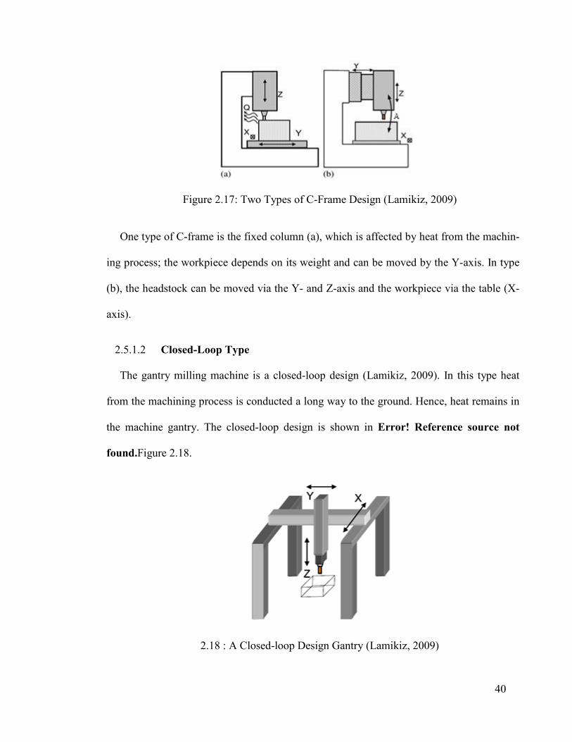
40
Figure 2.17: Two Types of C-Frame Design (Lamikiz, 2009)
One type of C-frame is the fixed column (a), which is affected by heat from the machin-
ing process; the workpiece depends on its weight and can be moved by the Y-axis. In type
(b), the headstock can be moved via the Y- and Z-axis and the workpiece via the table (X-
axis).
2.5.1.2 Closed-Loop Type
The gantry milling machine is a closed-loop design (Lamikiz, 2009). In this type heat
from the machining process is conducted a long way to the ground. Hence, heat remains in
the machine gantry. The closed-loop design is shown in Error! Reference source not
found. Figure 2.18.
2.18 : A Closed-loop Design Gantry (Lamikiz, 2009)

41
2.5.2 Static Behavior of Machine Tools Structure
Prior to manufacturing, static analysis software must be used to study the static behavior
of machine tool structure to identify several different types of machining error. Stress,
thermal error, deflection and deformation, allowable loads, etc., can be identified with
analysis software. Regarding the estimation of the static behavior of machine tool structure,
quite some research has been done including by Josef Mayr and colleagues (Mayr, 2014).
2.5.3 Dynamic Behavior of Machine Tools Structure
The dynamic behavior of machine tool structures in each frequency range can be simu-
lated as a set of individual modes of vibration. By modeling the structure with modal pa-
rameters, the vibration problem caused by resonance can be investigated (Maia, 1997). It is
still impossible to define the dynamic behavior of machine tool structures by drawing only
with a special degree of accuracy. However, considerable advances have been achieved in
the development of experimental methods to determine the mode shapes of machine tool
structures. Researchers (Y. Altintas, 2000; E. Budak, 1994; Tlusty, 1963) have introduced
static and dynamic analysis of machine tool structures involved in machining systems by
resting using stiffness measurements and modal analysis. Eman and Kim (Eman, 1983) in-
troduced a concept for the modal analysis of machine tool structures based on a parametric
representation of the measured responses. Multivariable autoregressive moving average
models were utilized in their study. Yuan et al. (Pedrammehr, 2012) presented the finite
element method for the modal analysis of machine tool structures. They determined the
first ten natural frequencies and mode shapes of the machine tool structure. Patwari et al.
(Patwari, 2010) presented experimental and analytical modal analysis techniques for struc-
tural dynamic evaluation processes of a vertical machining center. Experimental modal

42
analysis of different milling machine components was carried out in their study and the
theoretical mode shape of components was obtained by FEM. Zhijun et al. (Pedrammehr,
2012) proposed an approach to analyze the characteristics of machine tools by modal anal-
ysis and harmonic response. They carried out modal experiments to obtain modal frequen-
cy, damping and shape. Meanwhile, simulation and modal analysis using FEM served to
obtain accurate dynamic characteristics. Baker and Rouch (Baker, 2002) analyzed the in-
stability of the machining process through FEM but the result integrity was not validated by
the experimental results.
2.6 CNC Machine Tool Feed Drive Mechanisms
2.6.1 Background
A feed drive is used for positioning and orienting the cutting tool and workpiece during
machining (Altintas, et al., 2011). The machine tool carriages must carry the cutting tool
and workpiece to the desired operation location. Hence, the quality and productivity of
machine tools is determined from their positioning and speed accuracy. A feed drive sys-
tem is a mechanism that can support machine tool carriage motion via controllable posi-
tioning. A general schematic of feed drive hardware and its computer control structure is
shown in Figure 2.18
There are two types of feed drive. One is linear, which is powered directly by a linear
motor and the other is a rotary feed drive that works with a rotary motor. The ball screw
must convert rotary to linear motion in a rotary feed drive. Figure 2.20 shows linear and
rotary feed drives. The rotary feed drive consists of a machine worktable installed on the
linear guide and a ball screw supported by a servomotor. The rotational motion of the ball
screw will be converted into linear motion by a nut installed under the worktable. A CNC

43
controller controls the servomotor driver to position the worktable. The ball screw can be
connected directly to the servomotor or to a gear box to reduce rotation and increase feed
drive torque when heavy load is required. The servomotor is supported by a specific driver
connected to the CNC controller system. The worktable is positioned by a specific program
generated with a CAD/CAM system that is loaded onto the CNC machine tool controller.
The CNC program defines tool path segments that may consist of linear, circular, Sp-line or
other geometric motions.
Figure 2.19: Feed Drive Hardware Schematic (Altintas, et al., 2011)
Figure 2.20: Linear and Rotary Feed Drive Systems (Altintas, et al., 2011)

44
2.6.2 The Guideway
The guideway in a machine’s feed drive motion is one of the more important compo-
nents which can be used in this kind of mechanism. Several types of guideway may be used
in machine tools. Next, different guideway types are introduced. A slide-way schematic is
shown in Figure 2.21.
Figure 2.21: Guideway with Lubrication (L.N, 2009)
2.6.2.1 Slide-Ways (Friction Guides)
Friction guides have good damping, strength against impact loads and high load capacity
of up to 140 MPa. They are primarily used at speeds under 0.5 m/s (Díaz, 2009; L.N, 2009;
LNL de Lacalle, 2009). The slide-ways are lubricated by 1 mm deep lubrication slots locat-
ed on the moving part of the guide. The friction guides can also be coated with a few mil-
limeters of polymers in order to reduce friction. Various friction guide configurations are
shown in Figure 2.22.
(a) Schematics of Different Slide-Way Types
(b) Real Slide-Way Components
Figure 2.22: Friction slide-way configurations (Altintas, et al., 2011; L.N, 2009)

45
Different materials can be used to manufacture friction guides, for instance cast iron,
steel, bronze and some polymers.
2.6.2.2 Linear Guides
Low friction, high load capacity, stiffness and low structural damping are among the
specifications of linear guides. The two linear guide types are ball and rolling guides. Roll-
ing guides are manufactured with different sizes and loads and can be supplied with inte-
grated position sensors or racks to expedite the design and machine tool drive assembly. A
ball or roller linear guide is the “linearization” of the rolling bearing concept. Where lubri-
cation is limited, balls or roller linear guides substitute it. Balls are adequate for light loads
and high velocities and rollers work well for high loads but lower velocities. The
guideways are stiffer than friction slides, with lower opposition to displacement. Easy in-
stallation and maintenance by rapid substitution they have for guides or carriages. Machine
tool manufacturers can usually buy them already assembled with the required guide length.
They must be calculated and preloaded to a specific value for the carriage load to move.
The main drawback of this sliding system is low damping due to the direct metal-to-metal
contact. Some additional carriages especially designed for high damping using polymers or
inducing an oil film, can be inserted among rolling slides.
2.6.2.3 Hydrostatic Guides
To completely avoid metal-to-metal contact in hydrostatic guides, a sufficiently thick oil
film must always separate the sliding elements. To maintain the oil film, an external pump
continuously injects oil into the bearing. The stiffness of the bearing is proportional to the
oil supply pressure. Therefore, the main advantage of oil hydrostatic bearings is the ex-

46
tremely high damping ratio, which is very important when machining hard or brittle mate-
rials. The linear guide system is shown in Figure 2.23.
Figure 2.23: Linear Guide: (a) Roller Guide Model (RUE), (b) Special Hydrostatic
Guide (Altintas, et al., 2011; L.N, 2009)
2.6.3 CNC Gantry Machine Tool Feed Drive
Among the researchers accomplished in this field, Y. Altintas and colleagues (2011) re-
viewed different designs of machine tool feed drive systems and controls (Altintas, et al.,
2011). They discussed machine tool guide designs using friction, rolling elements, hydro-
static and magnetic levitation principles, mechanical drives based on ball screw, linear mo-
tors, electrical motors and sensors, the control of both rigid and flexible drive systems and
virtual feed modeling.
A. Verl and colleagues (2014 presented a double nut ball screw to improve its operating
characteristics (Verl, 2014). According to dynamic applications that often required ball
screws with high preloading values, this idea improved the operating characteristics by
proposing a novel design principle for ball screws using a double nut and spring. Fig-
ure 2.24 shows the idea and prototype of a double nut ball screw.
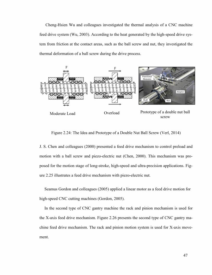
47
Cheng-Hsien Wu and colleagues investigated the thermal analysis of a CNC machine
feed drive system (Wu, 2003). According to the heat generated by the high-speed drive sys-
tem from friction at the contact areas, such as the ball screw and nut, they investigated the
thermal deformation of a ball screw during the drive process.
Moderate Load Overload Prototype of a double nut ball screw
Figure 2.24: The Idea and Prototype of a Double Nut Ball Screw (Verl, 2014)
J. S. Chen and colleagues (2000) presented a feed drive mechanism to control preload and
motion with a ball screw and piezo-electric nut (Chen, 2000). This mechanism was pro-
posed for the motion stage of long-stroke, high-speed and ultra-precision applications. Fig-
ure 2.25 illustrates a feed drive mechanism with piezo-electric nut.
Seamus Gordon and colleagues (2005) applied a linear motor as a feed drive motion for
high-speed CNC cutting machines (Gordon, 2005).
In the second type of CNC gantry machine the rack and pinion mechanism is used for
the X-axis feed drive mechanism. Figure 2.26 presents the second type of CNC gantry ma-
chine feed drive mechanism. The rack and pinion motion system is used for X-axis move-
ment.
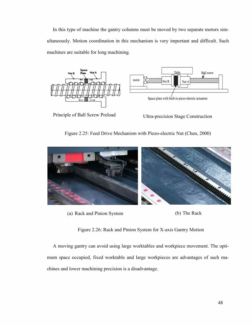
48
In this type of machine the gantry columns must be moved by two separate motors sim-
ultaneously. Motion coordination in this mechanism is very important and difficult. Such
machines are suitable for long machining.
Principle of Ball Screw Preload
Ultra-precision Stage Construction
Figure 2.25: Feed Drive Mechanism with Piezo-electric Nut (Chen, 2000)
(a) Rack and Pinion System
(b) The Rack
Figure 2.26: Rack and Pinion System for X-axis Gantry Motion
A moving gantry can avoid using large worktables and workpiece movement. The opti-
mum space occupied, fixed worktable and large workpieces are advantages of such ma-
chines and lower machining precision is a disadvantage.

49
2.7 Anti-backlash Mechanism in Feed Drive system
Rack and pinion systems are able to convert rotational motion into linear (Nsk Ltd,
2013). Rack and pinion systems have mainly been used for linear motion in CNC gantry
machines (worktable fixed type), robotics and linear motion systems with continuously
changing directions. Meanwhile, gears have almost become an integral part of power
transmission systems and machine instrumentation. Consequently, any error in gear trans-
mission will affect the performance of such systems (Brauer, 2003). When the system is
subjected to non-continuous motion with frequent direction reversal, this negative effect
will be conspicuous. Often, most such errors occur in robotic manipulators and the X-axis
motion of CNC gantry machines (Shibly, 1988). These mechanical components have non-
linear characteristics, such as gear backlash (R. Kalantari, 2009). Backlash is the shortest
distance between two teeth in mating gears. When gear teeth are not in contact, the trans-
mission force will be zero but when they are in contact, due to elasticity, the force is usual-
ly proportional to the angular position difference between the gears (R. Kalantari, 2009).
Backlash in rack and pinion systems generates different problems, such as machining pro-
cess errors, lower surface quality, noise and increased probability of damage (Li, 2007; Van
Dooren, 2001).
Anti-backlash gear systems are extensively used to reduce transmission error and obtain
precise, desirable output rotation or displacement. Available anti-backlash gears have been
used in many industrial applications, including gantry machine making and aerospace
(Shim, 2008). One method of anti-backlash gear design is to cut a gear into two halves,
with each half being ½ the thickness of the original gear. One of the gear halves is fixed to
the shaft and the other gear half is allowed to rotate on the shaft. Several coil springs are
used to push the two gear halves apart (radially) so that the gear teeth fit tightly between

50
the mating gear teeth. The coil springs are sized and compressed above normal operating
gear system torque. An example of an anti-backlash gear set is shown in Figure 2.27.
Figure 2.27: Anti-Backlash Gear (Imasaki, 1995)
2.7.1 Split Pinions
The simplest zero-backlash drive system utilizes a split pinion, which consists of two
pinion halves and an axial spring pack (Hale, 1994). The pinion halves mesh with the op-
posite tooth flanks on the same rack, eliminating backlash. One pinion half drives the axis
while the second pinion half is "preloaded" to remove the backlash. The preload setting of
the second pinion half is fully adjustable on the machine by turning the axial spring pack at
the end of the pinion shaft. Figure 2.28 shows the split pinion system.
Figure 2.28: Split Pinion System (Atlanta Drive Systems Inc., 2013 )

51
2.7.2 Controlling Backlash for Ultra-Precise Positioning
The general idea is to produce precise positioning and repeatability of rack and pinion
mechanisms by eliminating backlash, which can be accomplished using two pinions. One
pinion drives the axis and the other is for “preload” to remove backlash. Precise positioning
must be maintained during acceleration and deceleration, as well as movement direction
changes. Several different solutions to achieve a zero-backlash drive system with this idea
are presented next.
2.7.3 Dual Pinion Electrical Preload
One method to remove backlash in a rack and pinion is to use two motor/reducer assem-
blies with dual pinions operating on the same rack in a master/slave setup. One pinion
drives the axis while the second is "preloaded" to remove the backlash. The preload is cre-
ated electronically with a special motor controller; these systems can also be set up to drive
together during cycles when backlash is not critical. Figure 2.29 shows a dual pinion elec-
trical preload system.
Figure 2.29: Dual Pinion Electrical Preload (Atlanta Drive Systems Inc., 2013 )

52
2.7.4 Rack and Pinion Drive with Mechanical Preload
The mechanical preload is the same as the dual pinion electrical preload system, but one
motor includes a rotary spring. Figure 2.30 shows the rack and pinion drive with mechani-
cal preload.
Figure 2.30: Rack and Pinion Drive with Mechanical Preload (Atlanta Drive Systems
Inc., 2013 ; Lamikiz, 2009)
2.7.5 Roller Pinion System
The roller pinion system is an advanced, new technology that revolutionizes linear mo-
tion. The roller pinion system (RPS) provides zero backlash, very high positional accuracy,
unlimited length, unique design possibilities as well as the capability to achieve much high-
er performance levels in machine designs. The RPS line features an innovative rack and
pinion technology with extremely accurate positioning. This design eliminates the cumula-
tive error and thermal expansion error problems experienced with ball screw systems. The
opposing roller has contact with two or more teeth at the same time. This design eliminates
the costly and complex split and dual pinion systems required in most traditional rack and
pinion systems to achieve zero-backlash. The RPS line is designed with bearing-supported
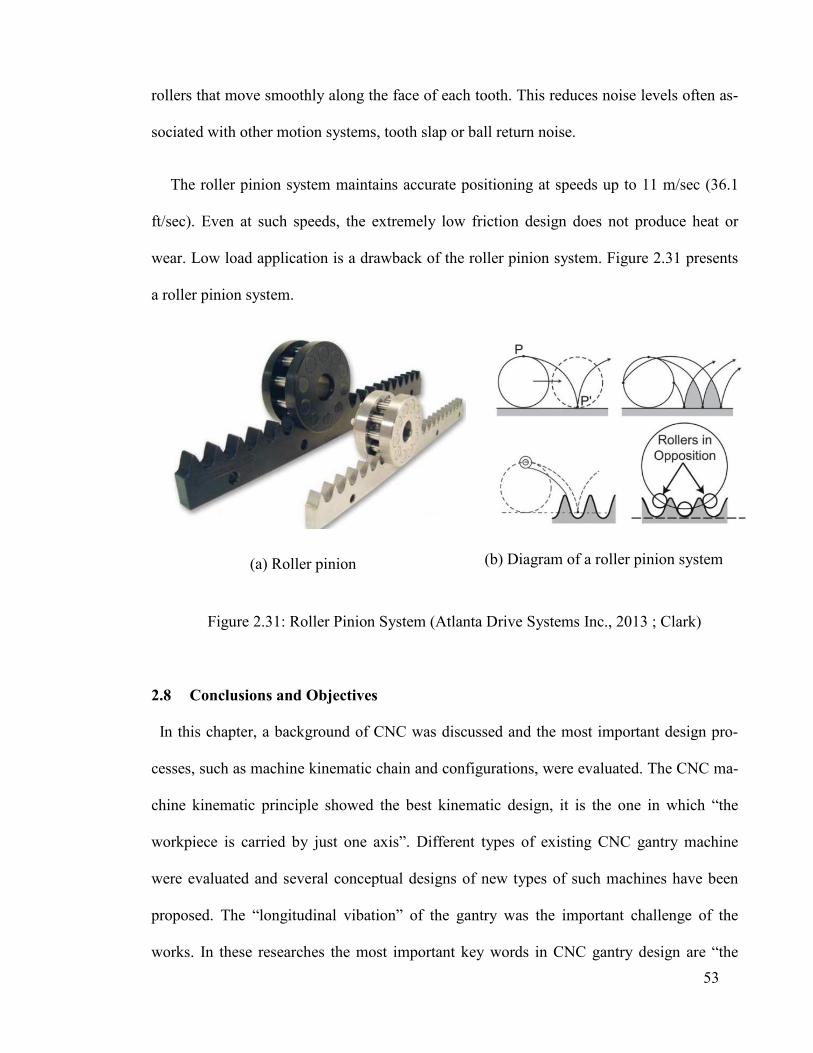
53
rollers that move smoothly along the face of each tooth. This reduces noise levels often as-
sociated with other motion systems, tooth slap or ball return noise.
The roller pinion system maintains accurate positioning at speeds up to 11 m/sec (36.1
ft/sec). Even at such speeds, the extremely low friction design does not produce heat or
wear. Low load application is a drawback of the roller pinion system. Figure 2.31 presents
a roller pinion system.
(a) Roller pinion
(b) Diagram of a roller pinion system
Figure 2.31: Roller Pinion System (Atlanta Drive Systems Inc., 2013 ; Clark)
2.8 Conclusions and Objectives
In this chapter, a background of CNC was discussed and the most important design pro-
cesses, such as machine kinematic chain and configurations, were evaluated. The CNC ma-
chine kinematic principle showed the best kinematic design, it is the one in which “the
workpiece is carried by just one axis”. Different types of existing CNC gantry machine
were evaluated and several conceptual designs of new types of such machines have been
proposed. The “longitudinal vibation” of the gantry was the important challenge of the
works. In these researches the most important key words in CNC gantry design are “the

54
design, modification and optimization” which were evaluated and discussed. Several re-
search works on the feed drive motion of CNC gantry machines have been done and evalu-
ated by the researchers. The rack and pinion with its “backlash” problems was evaluated;
existing gear anti-backlash mechanisms were evaluated.
In addition, this chapter summarized the relevant research associated with machine
tools, gantry machine tools and design criteria including “static” and “dynamic” behavior,
“cost and weight”. Tools were investigated, such as optimization and “multi-criteria deci-
sion making” for attaining optimal design solutions. The finite element method for achiev-
ing rapid and reliable solutions and analysis was also addressed. The content of this chapter
pointed out the scientific design methods and procedures that will be considered in subse-
quent chapters. The conceptual design of a new type of CNC gantry machine will be dis-
cussed in the next chapter.
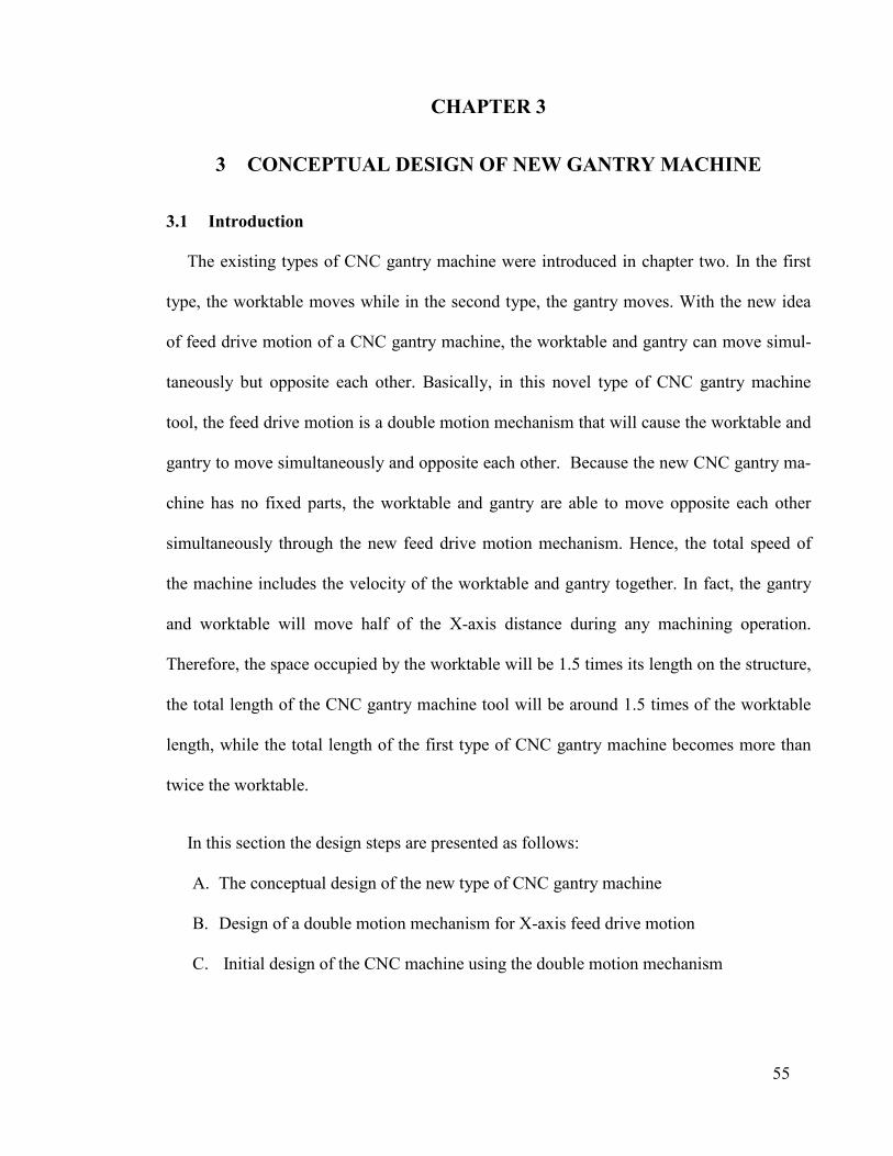
55
3.1 Introduction
The existing types of CNC gantry machine were introduced in chapter two. In the first
type, the worktable moves while in the second type, the gantry moves. With the new idea
of feed drive motion of a CNC gantry machine, the worktable and gantry can move simul-
taneously but opposite each other. Basically, in this novel type of CNC gantry machine
tool, the feed drive motion is a double motion mechanism that will cause the worktable and
gantry to move simultaneously and opposite each other. Because the new CNC gantry ma-
chine has no fixed parts, the worktable and gantry are able to move opposite each other
simultaneously through the new feed drive motion mechanism. Hence, the total speed of
the machine includes the velocity of the worktable and gantry together. In fact, the gantry
and worktable will move half of the X-axis distance during any machining operation.
Therefore, the space occupied by the worktable will be 1.5 times its length on the structure,
the total length of the CNC gantry machine tool will be around 1.5 times of the worktable
length, while the total length of the first type of CNC gantry machine becomes more than
twice the worktable.
In this section the design steps are presented as follows:
A. The conceptual design of the new type of CNC gantry machine
B. Design of a double motion mechanism for X-axis feed drive motion
C. Initial design of the CNC machine using the double motion mechanism
CHAPTER 3
3 CONCEPTUAL DESIGN OF NEW GANTRY MACHINE

56
3.2 The Conceptual Design of the Proposed CNC Gantry Machine
The conceptual design of the proposed CNC gantry machine is based on the concept of
the worktable and gantry moving simultaneously and in opposite directions (Figure 3.1).
According to the machine’s kinematic configuration discussed in chapter two, the configu-
ration of the new gantry machine is (LL) LLRR. It means there are two linear motions for
the X-axis (worktable and gantry simultaneously), another two linear motions belong to the
Y- and Z-axes and two rotational motions can be used for the rotary headstock (as a ma-
chine gantry accessory). In this design, the gantry and worktable can move at the same time
with a special mechanism, the double motion mechanism, which is introduced subsequent-
ly. The conceptual design of the new gantry machine with two different configurations is
shown in Figure 3.1.
As seen in Figure 3.1 (a), a ball screw is used for the machine’s worktable feed drive
motion. The ball screw will cause the worktable to move and the gantry will move in the
opposite direction from the worktable at the same time via the double motion mechanism
installed in the gantry columns. Figure 3.1 (b) shows that the gantry employs two servomo-
tors, which will move the double motion mechanism and the worktable will move in the
opposite direction from the gantry via the double motion mechanism. In this design, the
motion of the gantry is dependent on the worktable. The main feed drive motion is the only
difference between these two configurations. The main feed drive motion in the first (a)
configuration is via a ball screw supported by the servomotor while the main feed drive
motion in the second (b) configuration is via the double motion mechanism that is support-
ed by the servomotor directly. Therefore, the table and gantry can move in opposite direc-
tions over the same length. The worktable and gantry will move half of the machining op-
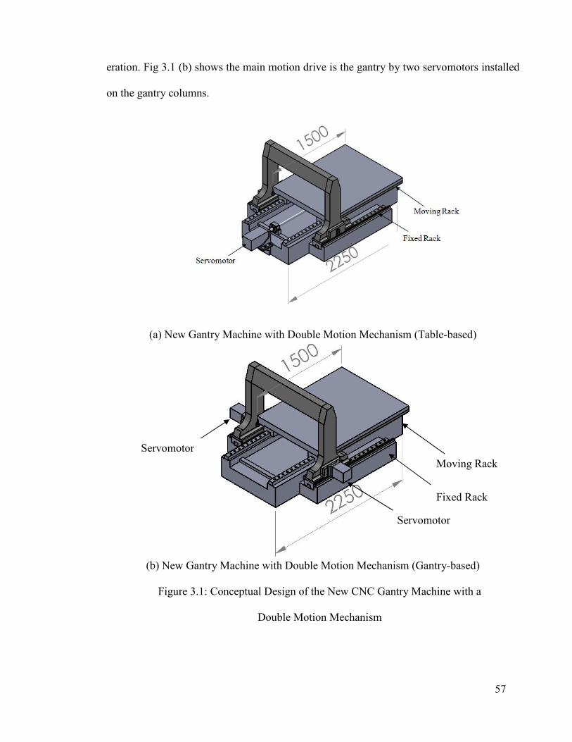
57
eration. Fig 3.1 (b) shows the main motion drive is the gantry by two servomotors installed
on the gantry columns.
(a) New Gantry Machine with Double Motion Mechanism (Table-based)
(b) New Gantry Machine with Double Motion Mechanism (Gantry-based)
Figure 3.1: Conceptual Design of the New CNC Gantry Machine with a
Double Motion Mechanism
Fixed Rack
Moving Rack
Servomotor
Servomotor

58
The conceptual design of the new CNC gantry machine was patented by University of Ma-
laysia after document preparation (M. H. S. R. Besharati, 2011). Several important ad-
vantages have been obtained from the conceptual design of this new type of CNC gantry
machine, including:
1. The total length of the machine is decreased, which affects other achievements, such
as the total cost of manufacturing and machine space occupied. In Figure 3.2 this advantage
is compared with the first existing CNC gantry machine types.
(a) Existing Type of Gantry (Initial Worktable Position)
(b) Existing Type of Gantry (End Worktable Position)
(c) New Proposed Type
(Initial Worktable Position)
(d) New Proposed Type
(End Worktable Position)
Figure 3.2: Comparison between First Type of Existing Gantry and the New Idea
As seen in Figure 3.2 (a, b) the worktable is 600 mm long and the machine structure
must be 1200mm because the worktable must move twice its length. In Figure 3.2 (c, d) the
machine structure is 900 mm long because the worktable must move half (300 mm) of its
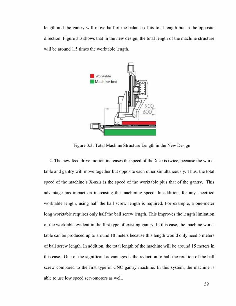
59
length and the gantry will move half of the balance of its total length but in the opposite
direction. Figure 3.3 shows that in the new design, the total length of the machine structure
will be around 1.5 times the worktable length.
Figure 3.3: Total Machine Structure Length in the New Design
2. The new feed drive motion increases the speed of the X-axis twice, because the work-
table and gantry will move together but opposite each other simultaneously. Thus, the total
speed of the machine’s X-axis is the speed of the worktable plus that of the gantry. This
advantage has impact on increasing the machining speed. In addition, for any specified
worktable length, using half the ball screw length is required. For example, a one-meter
long worktable requires only half the ball screw length. This improves the length limitation
of the worktable evident in the first type of existing gantry. In this case, the machine work-
table can be produced up to around 10 meters because this length would only need 5 meters
of ball screw length. In addition, the total length of the machine will be around 15 meters in
this case. One of the significant advantages is the reduction to half the rotation of the ball
screw compared to the first type of CNC gantry machine. In this system, the machine is
able to use low speed servomotors as well.
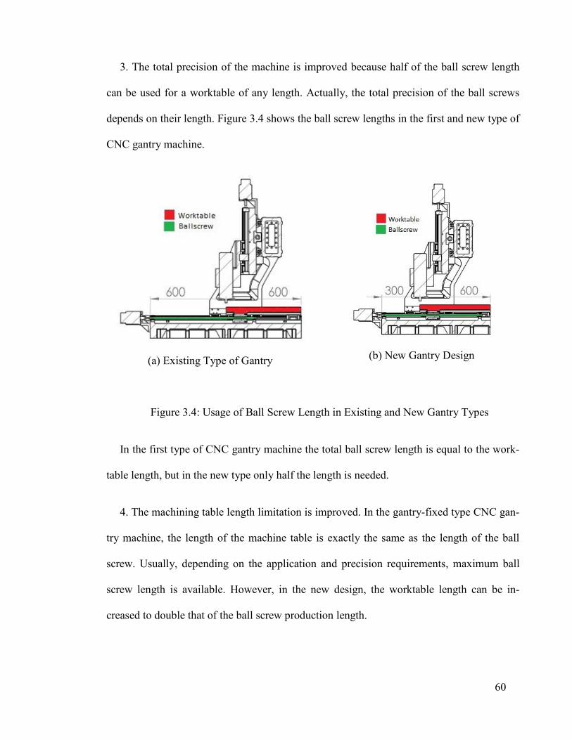
60
3. The total precision of the machine is improved because half of the ball screw length
can be used for a worktable of any length. Actually, the total precision of the ball screws
depends on their length. Figure 3.4 shows the ball screw lengths in the first and new type of
CNC gantry machine.
(a) Existing Type of Gantry
(b) New Gantry Design
Figure 3.4: Usage of Ball Screw Length in Existing and New Gantry Types
In the first type of CNC gantry machine the total ball screw length is equal to the work-
table length, but in the new type only half the length is needed.
4. The machining table length limitation is improved. In the gantry-fixed type CNC gan-
try machine, the length of the machine table is exactly the same as the length of the ball
screw. Usually, depending on the application and precision requirements, maximum ball
screw length is available. However, in the new design, the worktable length can be in-
creased to double that of the ball screw production length.

61
Other topics requiring investigation in future research on this subject include improving
machine efficiency, simplifying machine manufacturing and decreasing the total cost of the
machine.
3.3 Proposed Design of CNC Gantry Machine with Double Motion Feed Drive Sys-
tem
The concept of a double motion mechanism entails a special feed drive mechanism that
is able to produce motion for the gantry and worktable of the CNC gantry machine simul-
taneously and in opposite directions. Two types of double motion feed drive system can be
designed:
A –double motion mechanism based on a rack and pinion (dependent system),
B -double motion mechanism based on ball screw (independent system).
Both can be used for the same purpose, but there are some differences between them. By
the dependent system worktable and gantry they can move dependently and they can’t
move separately; this system is suitable for mass production applications. The independent
system can be used for universal machine, the worktable and gantry can move simultane-
ously and separately with the fore axis CNC controller.
3.3.1 Design of Double Motion Mechanism based on a Rack and Pinion system
The design of a double motion mechanism based on a rack and pinion is described
in this section and the other one will be described in section (4.2). Although it seems like a
simple design, it is not comprehensibly easily because the mechanism (with several pinions
and two racks) supports two parts that should move in opposite directions. This device has
two gear groups with several functions. The gantry and worktable’s “equal and simultane-

62
ous transferring motion” in “opposite directions” are among the gear system functions. Es-
sentially if the table moves, the gantry will move at the same time with a similar measure
but in the opposite direction. Therefore, the transfer ratio of the moving rack and fixed rack
is very important. The final designed mechanism is shown in Figure 3.5.
To understand how the double motion mechanism works, the layout of a double motion
gear system is depicted in Figure 3.5 (a). In the mechanism illustrated, two racks are used.
One is fixed and the other is moving; in any circumstance, the length of the moving rack
must be two times that of the fixed rack. In this instance, the fixed rack is 300 mm long and
is fixed on the machine structure, while a moving rack 600 mm long is installed on the
worktable. Two pinions are connected by two shafts and their ratio of transfer is 2/1. There
is a special rectangular component, which is representative of the CNC machine gantry’s
column and is able to carry both shafts. A pinion with 40 teeth is shown in front of the pic-
ture and it is fixated to the bottom shaft by a key. On the other side of this shaft the pinion
(20 teeth) is free to rotate on the shaft. Two additional gears are fixed on the upper shaft.
Although in the conceptual design (Figure 3.1) the gears of the double motion mechanism
are installed in the columns, in this step the double motion mechanism has been designed as
a separate part (Figure 3.5 (a, b)).
The mechanism functions in the following way. If the large pinion (Z = 40) moves 300
mm over the length of the fixed rack, it will rotate around N=300/ (Z*M*3.14) =1.194 rev
at the end of 300 mm (the gear module is M = 2 mm). Furthermore, the upper pinion
(Z=20) will rotate twice N = 2.388 RPM via pinion Z=40. Similarly, the corresponding pin-
ion on the other side of the shaft, pinion (Z=40) will rotated the same value, N = 2.388 rev.
Therefore, the engaged pinion (Z=20) will rotate around twice the value N = 4.777 rev it is
freewheel. This pinion will move a distance L= 599.991 mm. This means that it will move

63
the total length of the fixed rack in the opposite direction. In other words, if the big pinion
(Z = 40 at the front of the picture) rotates counterclockwise, the representative gantry will
move to the left and the moving rack (worktable) will move to the right simultaneously.
(a) Schematic of the Double Motion Sys-tem
(b) Double Motion Mechanism
Figure 3.5: Double Motion Gear Mechanism
Basically if the machine gantry moves only L= 300 mm, the worktable will move L=
300 mm in the opposite direction. In this case, if the total length of the machining operation
is L= 600 mm then the total space occupied by the machine will be L= 900 mm, while the
value for the existing type of CNC gantry machine (first type) will be L= 1200 mm.
The double motion mechanism is able to simultaneously support two linear axes of the
machine, the worktable and gantry. The ball screw system is used to drive the X-axis
(worktable) of the machine and the gantry can be simultaneously moved using the double
motion mechanism. Figure 3.6 shows the first design of the double motion mechanism as
well as its installation on the new machine structure.
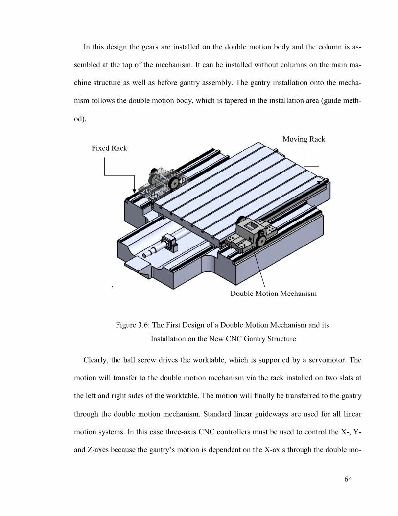
64
In this design the gears are installed on the double motion body and the column is as-
sembled at the top of the mechanism. It can be installed without columns on the main ma-
chine structure as well as before gantry assembly. The gantry installation onto the mecha-
nism follows the double motion body, which is tapered in the installation area (guide meth-
od).
`
Figure 3.6: The First Design of a Double Motion Mechanism and its
Installation on the New CNC Gantry Structure
Clearly, the ball screw drives the worktable, which is supported by a servomotor. The
motion will transfer to the double motion mechanism via the rack installed on two slats at
the left and right sides of the worktable. The motion will finally be transferred to the gantry
through the double motion mechanism. Standard linear guideways are used for all linear
motion systems. In this case three-axis CNC controllers must be used to control the X-, Y-
and Z-axes because the gantry’s motion is dependent on the X-axis through the double mo-
Fixed Rack Moving Rack
Double Motion Mechanism

65
tion mechanism and not the separate axis as shown in Figure 3.7. Therefore, the machine
has three simultaneously controllable axes.
Figure 3.7: The X-, Y- and Z-axes of the New CNC Gantry Machine
3.3.2 The Characteristics of the Double Motion Mechanism Based on Rack and Pin-
ion
This mechanism has three important characteristics:
1. The motion of the gantry is dependent on the motion of the worktable and vice versa.
2. The gantry and the worktable can be controlled by one axis (the X-axis). However,
the CNC gantry machine’s kinematic configuration is (LL) LLRR (four linear and two rota-
tional motions).
3. There is a backlash problem because a rack and pinion is used in this system.
3.3.3 Double Motion Mechanism Backlash Problem
The major problem with rack and pinion systems is backlash. It causes high transmis-
sion error, decreases precision and causes unsatisfactory surface quality in the manufactur-
66
ing process. Hence, solving the problem requires designing a complementary device for the
double motion mechanism. In fact, any error in the rack and pinion will lead to low ma-
chine performance (Brauer, 2003). The major deficiency of rack and pinion systems is in
the free play between the rack and pinion teeth (Lassâad Walha, 2009). When the system is
subjected to non-continuous motion with frequent direction reversal there will be signifi-
cant error. Nonetheless, there are many anti-backlash mechanisms to remove or control
backlash, as presented in chapter two.
3.4 Proposing a New Anti-backlash Mechanism in Rack and Pinion System
Various anti-backlash systems have been proposed for various applications, such as in-
dustrial robots, precision machining tools, radar antennas and precision servomotors. Anti-
backlash gear systems reduce the transmission error. As a result, precise and desirable out-
put rotation or displacement is gained. The double electric motor method, double helical
gear anti-backlash method, adjusting center distance method and spring-loaded anti-
backlash method (Allan, 1980; Boyuan, 2001; C. W. Cairnes, 1953; Guoming, 2001;
Imasaki, 1995; Kwon, 2004; Shim, 2008) are among the approaches used to eliminate
backlash in gear, rack and pinion systems.
Among the above-mentioned methods utilized to omit backlash, the spring-loaded anti-
backlash technique is widely employed in numerous fields. In this method, the coefficient
of the spring needs to be determined so that the mated teeth are always in contact for all
input torque. However, high preload in the system causes high contact and bending stress,
which may reduce gear lifespan. Other drawbacks of this method include complex manu-
facturing and installation, low transfer torque and high friction. In addition, if the teeth are
assumed to be rigid and static transmission error is neglected, the dynamic transmission

67
error (DTE) would always be in the system due to torsional spring deformation triggered by
the input torque.
In order to gain thorough insight into the dynamic and vibration behavior of gear sys-
tems, their modeling has been studied since 1920. Numerous investigations have been con-
ducted and accomplishments achieved regarding the dynamic modeling and analysis of
gear systems, with summaries compiled by Wang et al (Wang, 2003) and Özgüven and
Houser (Nevzat Özgüven, 1988).
More realistic and exact gear models with multi parameter excitation have been studied
in recent research works (Eritenel, 2012; He, 2007; Moradi, 2012). In addition, nonlinear
gear system dynamics have been vastly taken into account. For instance, the interactions
between time-varying mesh stiffness and clearance nonlinearities, as well as nonlinear dy-
namics of a gear rotor-bearing system with multiple clearance and dynamic transmission
errors (DTE) made by tooth deflection, which consequently lead to vibration, have been
investigated (Gregory, 1963; Kahraman, 1991a, 1991b). A relation between gear noise,
transmission error and vibration has been established in (Gill-Jeong, 2007; Wang, 2007). In
the mentioned research, the role of transmission error and dynamic behavior was consid-
ered in order to reduce gear noise. Typically, due to difficulty in solving nonlinear equa-
tions, the vibration response of dynamic gear models has been determined either by inte-
grating or applying other prevalent numerical methods (Kahraman, 1991a; Padmanabhan,
1996).
Until now, only few studies have been performed on nonlinear modeling, contact stiff-
ness and dynamic transmission error (DTE) in anti-backlash systems. For example, in
(Guoming, 2001) a simplified torsional dynamic model was established and the natural fre-
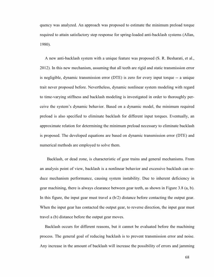
68
quency was analyzed. An approach was proposed to estimate the minimum preload torque
required to attain satisfactory step response for spring-loaded anti-backlash systems (Allan,
1980).
A new anti-backlash system with a unique feature was proposed (S. R. Besharati, et al.,
2012). In this new mechanism, assuming that all teeth are rigid and static transmission error
is negligible, dynamic transmission error (DTE) is zero for every input torque -- a unique
trait never proposed before. Nevertheless, dynamic nonlinear system modeling with regard
to time-varying stiffness and backlash modeling is investigated in order to thoroughly per-
ceive the system’s dynamic behavior. Based on a dynamic model, the minimum required
preload is also specified to eliminate backlash for different input torques. Eventually, an
approximate relation for determining the minimum preload necessary to eliminate backlash
is proposed. The developed equations are based on dynamic transmission error (DTE) and
numerical methods are employed to solve them.
Backlash, or dead zone, is characteristic of gear trains and general mechanisms. From
an analysis point of view, backlash is a nonlinear behavior and excessive backlash can re-
duce mechanism performance, causing system instability. Due to inherent deficiency in
gear machining, there is always clearance between gear teeth, as shown in Figure 3.8 (a, b).
In this figure, the input gear must travel a (b/2) distance before contacting the output gear.
When the input gear has contacted the output gear, to reverse direction, the input gear must
travel a (b) distance before the output gear moves.
Backlash occurs for different reasons, but it cannot be evaluated before the machining
process. The general goal of reducing backlash is to prevent transmission error and noise.
Any increase in the amount of backlash will increase the possibility of errors and jamming

69
during machining. Consequently, smaller amounts of backlash in gear systems lead to bet-
ter precision. Gear runout, error in profile, pitch and tooth thickness, helix angle and center
distance are all influential on increasing the amount of backlash. Excessive backlash must
be removed, particularly when the drive is frequently reversed or high load is proposed.
(a) Backlash Schematic
(b) Backlash, j, between Two Gears
Figure 3.8: Gear Backlash Schematic
However, high cost is needed to reduce backlash during gear manufacturing. Thus, machin-
ing accuracy will be affected when decreasing backlash. Any increase or decrease in the
distance of the centers between two gears will be transformed into backlash. There are dif-
ferent ways to design backlash in gears, with several kinds in rack and pinion: circular
backlash jt, normal backlash jn, center backlash jr and angular backlash jθ (°) (
Figure 3.9).
3.5 New Anti-backlash Design in a Rack and Pinion System
To solve the backlash problem it is necessary to design suitable anti-backlash for the
double motion mechanism. A new concept for a gear backlash compensation mechanism
(GBCM) is introduced for the first time. It is applicable for any other industrial application
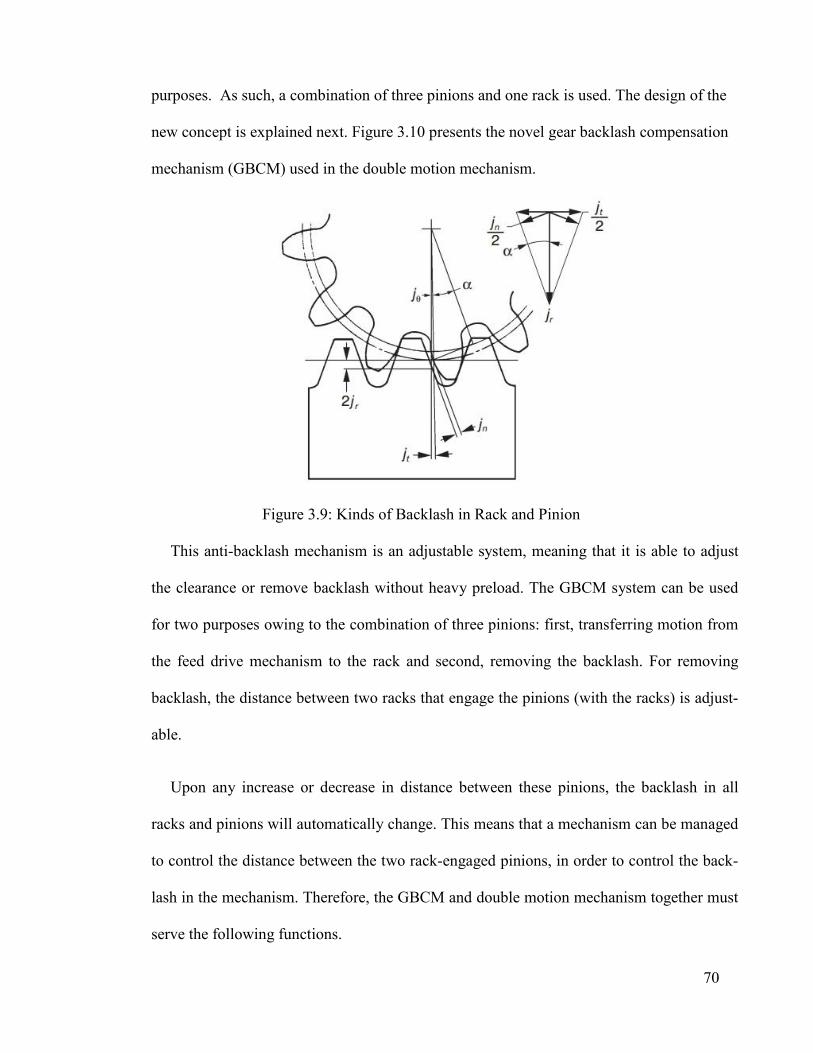
70
purposes. As such, a combination of three pinions and one rack is used. The design of the
new concept is explained next. Figure 3.10 presents the novel gear backlash compensation
mechanism (GBCM) used in the double motion mechanism.
Figure 3.9: Kinds of Backlash in Rack and Pinion
This anti-backlash mechanism is an adjustable system, meaning that it is able to adjust
the clearance or remove backlash without heavy preload. The GBCM system can be used
for two purposes owing to the combination of three pinions: first, transferring motion from
the feed drive mechanism to the rack and second, removing the backlash. For removing
backlash, the distance between two racks that engage the pinions (with the racks) is adjust-
able.
Upon any increase or decrease in distance between these pinions, the backlash in all
racks and pinions will automatically change. This means that a mechanism can be managed
to control the distance between the two rack-engaged pinions, in order to control the back-
lash in the mechanism. Therefore, the GBCM and double motion mechanism together must
serve the following functions.
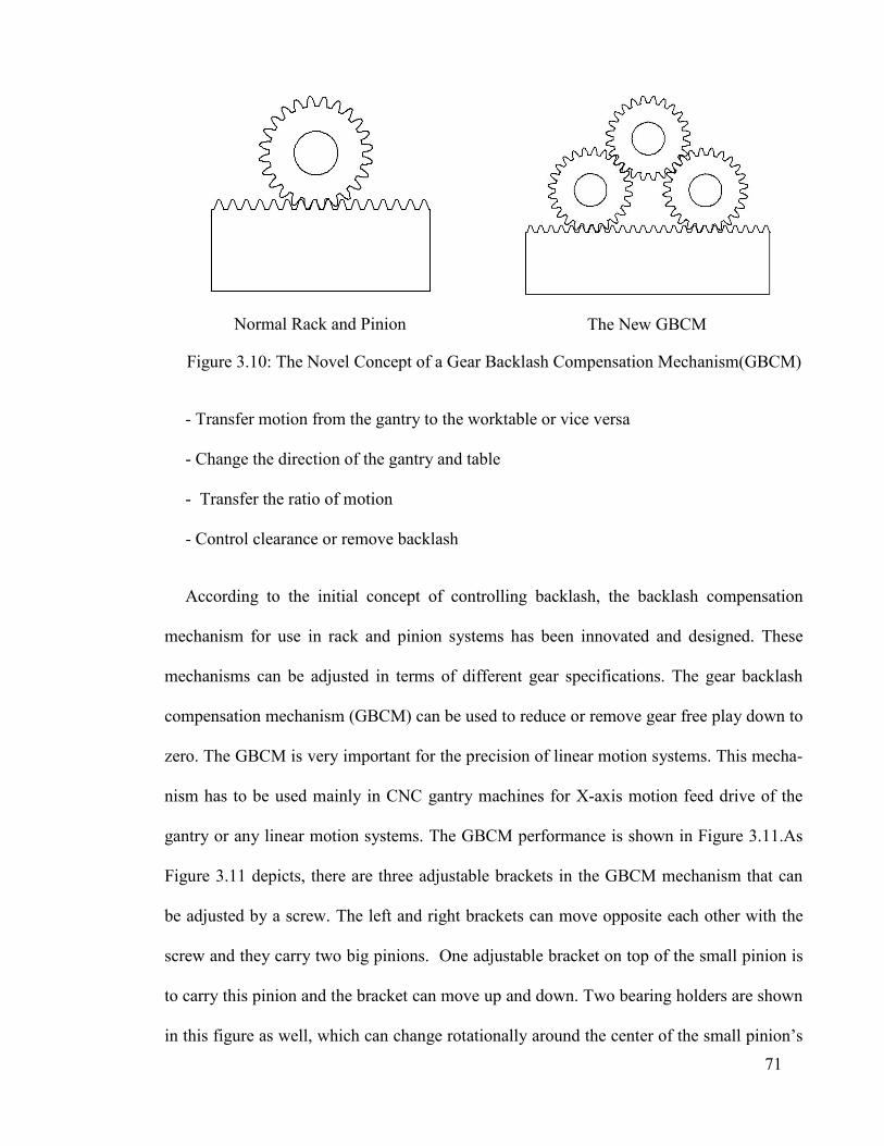
71
Normal Rack and Pinion
The New GBCM
Figure 3.10: The Novel Concept of a Gear Backlash Compensation Mechanism(GBCM)
- Transfer motion from the gantry to the worktable or vice versa
- Change the direction of the gantry and table
- Transfer the ratio of motion
- Control clearance or remove backlash
According to the initial concept of controlling backlash, the backlash compensation
mechanism for use in rack and pinion systems has been innovated and designed. These
mechanisms can be adjusted in terms of different gear specifications. The gear backlash
compensation mechanism (GBCM) can be used to reduce or remove gear free play down to
zero. The GBCM is very important for the precision of linear motion systems. This mecha-
nism has to be used mainly in CNC gantry machines for X-axis motion feed drive of the
gantry or any linear motion systems. The GBCM performance is shown in Figure 3.11.As
Figure 3.11 depicts, there are three adjustable brackets in the GBCM mechanism that can
be adjusted by a screw. The left and right brackets can move opposite each other with the
screw and they carry two big pinions. One adjustable bracket on top of the small pinion is
to carry this pinion and the bracket can move up and down. Two bearing holders are shown
in this figure as well, which can change rotationally around the center of the small pinion’s
72
axis. There are three shafts for the pinions and each bearing holder has two roller bearings
to keep the shafts. In this mechanism all the pinions are installed on the shafts and can ro-
tate smoothly.
The distance between the two large pinions can change -- it can be increased or decreased
when the adjustable bracket of the small pinion moves up or down. Thus, these two big
gears can move opposite each other thanks to the adjustable brackets, so the total backlash
between the rack and pinions will be compensated for as well. Figure 3.12 shows the entire
GBCM that can be used in linear motion systems.
The advantages of the GBCM over other similar systems are mentioned as follows.
a) In the new anti-backlash mechanism, the numerous gear teeth are engaged with others
simultaneously. This means that more power and torque can be transferred by this mecha-
nism. Most existing systems are functional for normal torque and power, like anti-backlash
gear.
b) The contact area of the gear teeth is greater in the new mechanism, so movement will
be fluent.
c) The gear backlash is easily controlled by the combination of three pinions.
d) The backlash can be controlled or removed without heavy preload requirement. All
other anti-backlash systems that can be used in CNC gantry machine feed drive motion re-
quire heavy preload to remove the backlash.
e) The requirement of clearance is adjustable, whereas in existing systems this is not
possible.
f) One motor is exploited to drive the GBCM, which is one of most important ad-
vantages of this innovation.

73
(a) Rack and Pinion System
(b) The Slats
(c) The Brackets
(d) Assembly of Slats and Brackets
(e) The GBCM Body
(f) The GMCM Mechanism
Figure 3.11: The Gear Backlash Compensation Mechanism (GBCM)
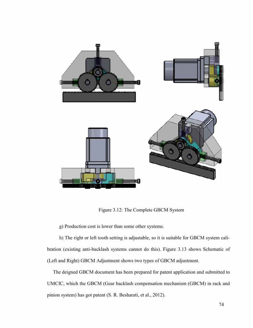
g) Production cost is lower than some other systems.
h) The right or left tooth setting is adjustable, so it is suitable for GBCM system cal
bration (existing anti-backlash systems cannot do this).
(Left and Right) GBCM Adjustment
The deigned GBCM document has been prepared for patent application and submitted to
UMCIC, which the GBCM (Gear backlash compensation mechanism (GBCM) in rack and
pinion system) has got patent
Figure 3.12: The Complete GBCM System
roduction cost is lower than some other systems.
h) The right or left tooth setting is adjustable, so it is suitable for GBCM system cal
backlash systems cannot do this). Figure 3.13 shows
) GBCM Adjustment shows two types of GBCM adjustment.
The deigned GBCM document has been prepared for patent application and submitted to
he GBCM (Gear backlash compensation mechanism (GBCM) in rack and
pinion system) has got patent (S. R. Besharati, et al., 2012).
74
h) The right or left tooth setting is adjustable, so it is suitable for GBCM system cali-
shows Schematic of
shows two types of GBCM adjustment.
The deigned GBCM document has been prepared for patent application and submitted to
he GBCM (Gear backlash compensation mechanism (GBCM) in rack and

75
(a) Internal Adjustment
(b) External Adjustment
Figure 3.13 : Schematic of (Left and Right) GBCM Adjustment
3.6 Proposed Double Motion Feed Drive with Anti-backlash Mechanism in Rack
and Pinion System
The GBCM was installed in the double motion mechanism to avoid the backlash prob-
lem of the rack and pinion system. First, for moving the pinions to the left, right, up and
down, six separate brackets were designed.
Furthermore, four suitable double brackets for rotational angular movement were de-
signed; then the new CNC double motion system was installed in the new type of CNC
gantry machine structure as shown in Figure 3.14.
In this design, the structure has been modified based on the new double motion mecha-
nism. Also, the ball screw will be derived the worktable and the motion will become a dou-
ble motion in this way. Then the gantry will be moved by the new, double motion mecha-
nism without backlash. For easy gantry assembly, a special plate has been added to install
linear blocks (Figure 3.14) and the double motion mechanism will be assembled on top of
this plate and the gantry columns on top of the double-motion mechanism.
76
3.7 Nonlinear Dynamic Analysis of Anti-Backlash Gear Mechanism for Less Dy-
namic Transmission Error
Subsequently, a new anti-backlash gear mechanism design (GBCM) comprising three
pinions and a rack is introduced. This mechanism offers several advantages compared to
conventional anti-backlash mechanisms, such as lower transmission error as well as lower
required preload.
The nonlinear dynamic modeling of this mechanism is developed to acquire insight into its
dynamic behavior. It is observed that the amount of preload required to diminish the back-
lash depends on the applied input torque and nature of periodic mesh stiffness. Then an at-
tempt is made to obtain an approximate relation and find the minimum required preload to
preserve the system’s anti-backlash property and reduce friction and wear on the gear teeth.
The mesh stiffness of the mated gears, rack and pinion is achieved via finite element meth-
od using ANSYS workbench and is approximated by Fourier series in the equation of mo-
tion.
A numerical method is used to solve the differential equation of motion and the total
transmission error of the system and spectral content is computed.
Assuming that all teeth are rigid and static transmission error is negligible, dynamic
transmission error (DTE) is zero for every input torque, which is a unique trait, not yet pro-
posed in previous research.
Gear mechanisms are used extensively in modern power transmission systems owing to
their remarkable advantages. Some gear system applications include power generation,
mining, transportation and refining industries.

77
(a) The Slats
(b) The Shafts and Angular Bearings
(c) The Brackets
(d) Double Motion Mechanism with GBCM
Figure 3.14: The Double Motion Mechanism with the GBCM
3.7.1 The Concept
The configuration of the new anti-backlash mechanism comprises three pinions, one
rack, two bearing holders and three adjustment slides, as shown in Figure 3.15.
In this mechanism, the main pinion is the driver to which input torque is applied. An op-
timum amount of preload is exerted on the main pinion by an adjusting system to ensure
Special plate

78
that all gear teeth remain in contact in various operating conditions. Afterward, the distance
between the transmission pinion and the rack is fixed using a mount screw. Contact among
the teeth of the mated gears ensures that the rotation transmission will be continuous.
In fact, transferring clockwise and counterclockwise rotation is accomplished using the
right and left transmission pinions, respectively. It is not essential to use a spring to provide
the required preload and it is sufficient to use a screw to supply an accurate amount of pre-
load. Compared with a spring-loaded mechanism, assuming that teeth are rigid and static
transmission error is zero, this system would provide zero transmission error. In order to
verify the applicability of the mechanism concept to eliminate backlash, a simulation of the
mechanism in Motion Analysis of Solidworks CAD software has been investigated.
Figure 3.15 shows the modeled mechanism and preload as well as rotational motor applied
on the mechanism. The contact constrains were applied between the adjacent gears and
rack. First, force was applied as preload to ensure contact between adjacent teeth.
(a) The Main Mechanism
(b) Gear Configuration
Figure 3.15: Configuration of the New Anti-backlash Mechanism

79
Next, the motor began rotating the main pinion clockwise and with constant angular ve-
locity at the 1st second and altered the direction at the 3rd second as well as Motor Rotation
(Clockwise from 1st Second and Counterclockwise from 3rd Second) on Main Pinion
Figure 3.16 shows the linear displacement of the rack. The small variation in rack dis-
placement before the 1st second, results from the applied preload, which attempts to elimi-
nate the initial clearance between teeth. As seen in this figure, the rack begins to move im-
mediately after motor initiation. This result verifies the anti-backlash characteristics of the
proposed mechanism for both directions.
There is a possibility of tooth separation due to the system’s dynamic complicity, which
depends on internal (variable mesh stiffness) and external system excitation (input torque).
In order to better understand the dynamic behavior of the system and determine the opti-
mum amount of preload, the next section deals with nonlinear dynamic system modeling
assuming variable mesh stiffness. For investigating the dynamic behavior of the new anti
backlash mechanism, the modal analysis is required to extract the natural frequency of the
mechanism.
Modal analysis is mainly a technique used to obtain the vibration characteristics of a
structure. Hence, the dynamic behavior of the new anti backlash mechanism with Steel
“ASTM-A36” was analyzed to identify the minimum natural frequencies. The entire modal
analysis process was done using ANSYS (engineering simulation software) by finite ele-
ment method. In order to make a finite element model, a three dimensional model of the
new anti backlash mechanism with ANSYS Workbench was considered. The three dimen-
sional model with SolidWorks software was performed. The model was exported to
ANSYS Workbench and the necessary input data as material properties like modulus of
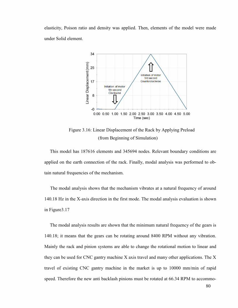
80
elasticity, Poison ratio and density was applied. Then, elements of the model were made
under Solid element.
Figure 3.16: Linear Displacement of the Rack by Applying Preload
(from Beginning of Simulation)
This model has 187616 elements and 345694 nodes. Relevant boundary conditions are
applied on the earth connection of the rack. Finally, modal analysis was performed to ob-
tain natural frequencies of the mechanism.
The modal analysis shows that the mechanism vibrates at a natural frequency of around
140.18 Hz in the X-axis direction in the first mode. The modal analysis evaluation is shown
in Figure 3.17
The modal analysis results are shown that the minimum natural frequency of the gears is
140.18; it means that the gears can be rotating around 8400 RPM without any vibration.
Mainly the rack and pinion systems are able to change the rotational motion to linear and
they can be used for CNC gantry machine X axis travel and many other applications. The X
travel of existing CNC gantry machine in the market is up to 10000 mm/min of rapid
speed. Therefore the new anti backlash pinions must be rotated at 66.34 RPM to accommo-
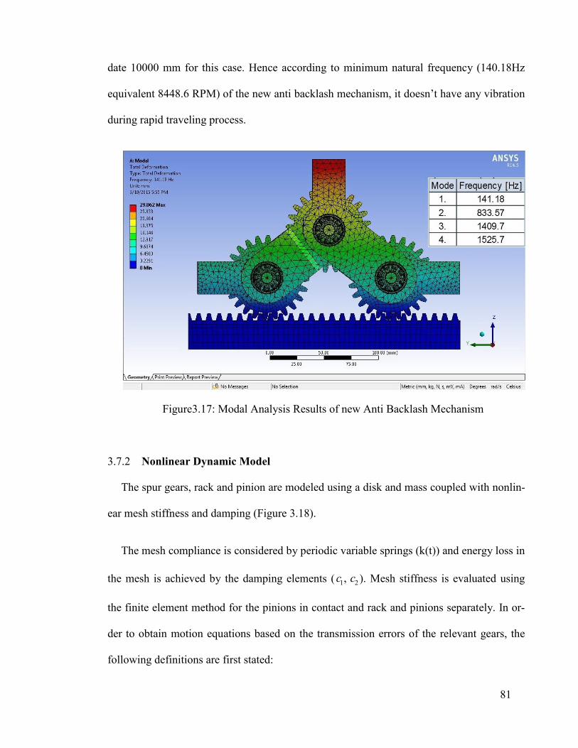
81
date 10000 mm for this case. Hence according to minimum natural frequency (140.18Hz
equivalent 8448.6 RPM) of the new anti backlash mechanism, it doesn’t have any vibration
during rapid traveling process.
Figure 3.17: Modal Analysis Results of new Anti Backlash Mechanism
3.7.2 Nonlinear Dynamic Model
The spur gears, rack and pinion are modeled using a disk and mass coupled with nonlin-
ear mesh stiffness and damping (Figure 3.18).
The mesh compliance is considered by periodic variable springs (k(t)) and energy loss in
the mesh is achieved by the damping elements ( 1 2, c c ). Mesh stiffness is evaluated using
the finite element method for the pinions in contact and rack and pinions separately. In or-
der to obtain motion equations based on the transmission errors of the relevant gears, the
following definitions are first stated:

82
Figure 3.18: Model of Anti-backlash Gear Mechanism
12 1 1 2 2x R R (3.1.a)
13 1 1 3 3x R R (3.1.b)
24 2 2x R x (3.1.c)
34 3 3x R x (3.1.d)
where 12x , 13x , 24x and 34x are relative transmission error between pinions 1 and 2, 1 and 3,
pinion 2 and rack and pinion 3 and rack, respectively. 1 2 3, ,R R R are gear radii, 1 2 3, ,
are the gears’ rotational displacements and x is the rack’s linear displacement. These rela-
tions are defined such that compression always gives positive transmission error.
For simplicity, Eq. (3.1) can be stated in matrix form as follows:
{ } [ ]{ }x P (3.2.a)
where

83
12 1 1 2
13 2 1 3
224 3
334
0 0
0 0} , [ ]
0 0 1
0
{ } , {
0 1
R R
R RP
R
R
x
xx
x
xx
(3.2.b)
Using the Newtonian laws of motion and assuming that the shafts and bearings are rigid,
the dynamic equations for the gears and rack are obtained separately, as in Eq. (3.3). In the
following equations, 1 2 3, ,J J J represent the mass inertial moment of gears 1, 2, 3 respec-
tively; m is the mass of the rack; and T and F are torque applied on gear 1 and external
force applied on the rack, respectively.
1 1 1 2 1 2 1 1 3 1 1 2 1 1 2 1 1 3 1 1 3 1( ) ( ) ( ) ( )J x R cx R t fc k Rx xR k t f T (3.3.a)
2 2 1 1 2 2 2 2 4 2 1 2 1 1 2 2 2 4 2 2 4 2( ) ( ) ( ) ( )J c x R c R k t f R kx Rxt fx (3.3.b)
3 3 1 1 3 3 2 3 4 3 1 3 1 1 3 3 3 4 2 3 4 3( ) ( ) ( ) ( )J c x R c R k t f R k tx x xf R (3.3.c)
2 24 2 34 24 2 24 34 2 34( ) ( ) ( ) ( )mx c c k t f k t fx x x x F (3.3.d)
where 1 is mesh compression displacement of gears 1-2 and 1-3 and likewise, 2 is mesh
compression displacement of gear 2-rack and gear 3-rack due to applied preload. 1 and 2
are computable using 1
/ 2 sin( / 2)p
F and 1 12 2 24k k or
1 13 2 34k k which result
from static analysis for the main pinion and transmission pinions. pF and represent the
preload and angle between the center lines of the main and transmission pinions shown in
Figure 3.15b, respectively and f is a nonlinear displacement function due to backlash and
is defined as:

84
, 0
) 0 , 0
,
(f b
b b
(3.4)
where b is backlash.
Equation (3.3) can be expressed in matrix form as follows:
} [ ]{ } [ ( )]{ ){ ( } { }C x K t f x F (3.5)
where
13 112 1
1 1
1 12 12 2 2
1 13 2 2
2 24 13 3 34 3
2 34 3 3
3424
24
0( )( )
( )
0
0 0
{ ( )} , [ ( )]
0
( ) ( )
( )
( ) (0
0 0
) ( )
( )
( )( )
t Rt R
f t R t R
f
f t
kk
J J
x k k
x J Jf x
R t R
f
tt
K tx k k
x J J
kk
m m
1 1 1 1
1 1
11 2 2 2
2 2
1 3 2 3
3 3
2 2
0 0
0 00
[ ] , { }0
0 0
0 0
c R c R
J J T
Jc R c R
J JC F
c R c R
J J F
mc c
m m
By multiplying both sides of Eq. (3.5) by [ ]P defined in (3.2.b), the following equation
that is completely based on the relative transmission error vector is obtained:
{{ } [ ( )] )} [ ]{ } { }(fx K t x C x F (3.6)
where
[[ ( ) ] )] [ ( ]PK Kt t
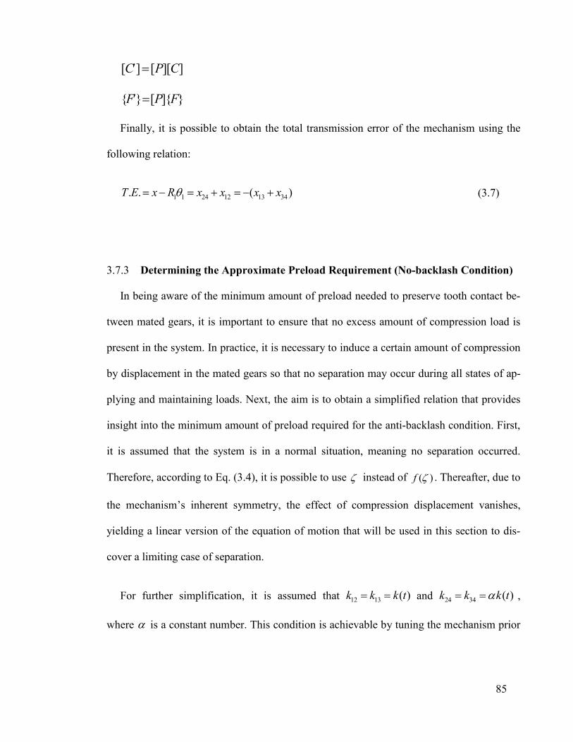
85
[ ] [ ][ ]C P C
{ } [ ]{ }F P F
Finally, it is possible to obtain the total transmission error of the mechanism using the
following relation:
1 1 24 12 13 34. . ( )T E x R x x x x (3.7)
3.7.3 Determining the Approximate Preload Requirement (No-backlash Condition)
In being aware of the minimum amount of preload needed to preserve tooth contact be-
tween mated gears, it is important to ensure that no excess amount of compression load is
present in the system. In practice, it is necessary to induce a certain amount of compression
by displacement in the mated gears so that no separation may occur during all states of ap-
plying and maintaining loads. Next, the aim is to obtain a simplified relation that provides
insight into the minimum amount of preload required for the anti-backlash condition. First,
it is assumed that the system is in a normal situation, meaning no separation occurred.
Therefore, according to Eq. (3.4), it is possible to use instead of )(f . Thereafter, due to
the mechanism’s inherent symmetry, the effect of compression displacement vanishes,
yielding a linear version of the equation of motion that will be used in this section to dis-
cover a limiting case of separation.
For further simplification, it is assumed that 12 13 ( )k k k t and 24 34 ( )k tk k ,
where is a constant number. This condition is achievable by tuning the mechanism prior

86
to employing it. It is fairly reasonable for the variable mesh matrix to be expressible only
by the constant and periodic cosine wave as follows:
0 1 cos[ ( )] ( )[ ]mK at k a t (3.8)
where is mesh frequency and 1[ ] [ ( )]
( )K t
k t . It is assumed that the transmission error
vector and rotation vector are expressed as:
0 1 2} { }sin{ ( )} { { }cosx t x t xx t (3.9.a)
0 1 2} { }sin{ ( ) { o} c s{ }t t t (3.9.b)
By substituting relations (3.8), (3.9.a) and (3.9.b) in the linear form of Eq. (3.5), the fol-
lowing equation is obtained:
2 21 2 1 2
0 1 0 1 2
{ }sin { }cos }cos }si[ ] n
cos } { }
( { { )
( )[ ]({ { ) { }sin }cosm
t t C x t x t
k a t x t x tx Fa
(3.10)
By collecting similar terms and equating them with each other we have:
0 0[ } { }]{ 0m xk a F (3.11.a)
21 2 0 1{ } [ } [ }]sin[ ]{ ]{ 0m tk aC x x (3.11.b)
22
1 1 0 0 2[ ]{ ]{{ } [ } [ } [ }]c{ 0o] sm mx x x tC k a k a (3.11.c)
Considering the fact that in steady state response the natural frequency of a system is very
large compared to mesh frequency, it can be assumed that the damping and inertial forces
are much smaller than the spring force and are negligible, therefore:
0 0[ { } { }]mk a x F (3.12.a)

87
0 1 1[ }]{ 0 { } 0m xk a x (3.12.b)
11 0 0 2 2 0
0
[ } [ } }]{ ] { {{ 0 }m mx xa
k a k a xa
x (3.12.c)
Multiplying both sides of Eq. (9.a) by 0[ ]mk a gives:
0 0 0 0 1 0 2]{ ( )} ][ [ } [ { }sin [ }cos{ ] ]{m m m ma a a x ak x t k x k t k x t (3.13.a)
Using the results obtained in Eq. (3.12) yields the following relation:
0 0 1 0 0 1 0
0 1 0
[ [ / ){ }cos [ }co]{ ( )} s
[ / )co
{ } ]( { } ]{
]{ ( )} { } ( s { }
m m m
m
k x t F k a t F a x t
k x t
a a a x k
a aF ta F
(13.b)
In order to obtain the maximum amount of transmission error, the maximum value of the
right side of Eq. (3.13.b) was considered. Therefore, the following equation is inferable:
0 max 1 0]{ } (1[ / ){ }mk x a Fa a (3.13.c)
With insight to Eq. (3.8) using (3.13.c), we obtain the following relation:
m ax[ ]{ } { }eqK x F (3.13.c)
where [ ]eqK is the equivalent stiffness matrix in which ( )k t is replaced by
1 0 0(1 / ) /m
eq
kk
a a a
.
Equation (13.c) states that the maximum absolute transmission error considering the sys-
tem’s dynamic behavior due to the periodic variation of mesh stiffness is obtainable by re-
placing e qk by ( )k t in the system and carrying out static analysis instead of dynamic anal-
ysis for the main pinion and rack considering external torque and load. In fact, this relation
lets us analyze the system statically rather than using sophisticated dynamic analysis to

88
gain insight into the dynamic behavior. Performing static analysis thus yields maximum
transmission error, which must be covered by initial compression displacement to eliminate
tooth separation. The next relation obtained keeping the explained viewpoint in mind, indi-
cates that the initial compression displacement applied in the system through the preload
must be more than the minimum compression displacement in the system considering the
equivalent mesh stiffness is eqk :
max ),(2 2eq eq
T F
k R k
(3.14)
Assuming that sufficient preload is applied in the system so no separation will occur, the
amount of additional preload will not have any influence on the transmission error value
and the equation of motion, (3.3), will become completely linear.
3.7.4 Case Study for Pinion-pinion and Rack-pinion
In this section a numerical example is discussed to obtain transmission error variation
considering step torque input and variable mesh stiffness.
3.7.4.1 Mesh Stiffness of Pinion-Pinion and Pinion-Rack
Many investigations on gear mesh stiffness have been carried out and it has been con-
cluded that the mesh stiffness of mated gears is periodic, non-constant and dependent on
the applied torque. The varying mesh stiffness is one of the important sources of internal
system excitation and it also affects the transmission error value. The mesh stiffness value
comprises bending, shear, gear body torsion and Hertzian contact stress, which act in series
to form mesh stiffness. Due to the complexity of calculating mesh stiffness, the finite ele-
ment method is normally employed to achieve accurate results.

89
For a numerical investigation, the mesh stiffness of mated gears and mated rack and pin-
ion was computed with the finite element method. ANSYS workbench was used to obtain
the deformation that occurred for the prescribed force and torque. Mesh stiffness was then
computed by dividing the applied torque or load by the resulting rotational or linear dis-
placement. Table 3.1 presents the physical parameters applied in the calculation.
Table 3.1: Physical parameters used in the calculation
Number of
teeth Z Module m,
mm Mass (kg)
Face width (mm)
Diameter of pitch circle
(mm)
Length (mm)
Height (mm)
Gear 24 2 0.222 20 48 - -
Rack 75 2 0.683 20 - 150 32
The modeling and analysis of two mated gears as well as rack-pinion are shown in 3.19.
The relevant mesh stiffness results obtained are given in Figure 3.20. The alternation of
mesh stiffness with rotation is due to the transition from a single to a two-tooth contact re-
gion. This phenomena will be repeated by 360/N, where N is the number of gear teeth. The
frequency of mesh stiffness is r*N, where r is the gear’s rotational speed.
Due to the periodic nature of mesh stiffness, its representation is approximated by Fou-
rier series and its coefficient is utilized to calculate initial compression displacement by
substituting in Eq. (3.14). However, in simulation, instead of approximation, direct use of
mesh stiffness as presented in 3.19 is applied to ensure simulation result accuracy. For fur-
ther simplification, it is assumed that pinion-pinion mesh stiffness can be derived by multi-
plying the mesh stiffness of the rack-pinion by as follows:

90
12 13 24 34 m
2
10( ) ( ) ( ) ( ) ( cos )i
i
i
k t k t k k tt t k b b
(3.15)
where 0.76 and 523000 /mk N mm , 0 0.9494b , 1 0.08264b , 2 0.03548b are
determined with the curve fitting method using the MATLAB curve fitting toolbox.
3.7.4.2 Transmission Error
The numerical method is applied to solve the matrix form of the equation of motion
(3.6). For simulation purpose, it is assumed that all pinions are identical. The parameters
employed in the simulation are presented in Table 3.2 for pinions and rack. The Rung-
Kutta method, one of the most important iterative solvers of ordinary differential equations
(ODE), was employed in MATLAB through the ode45 command. The time increment se-
lected was 0.0001 seconds (the increment is selected upon rotational speed and number of
gear teeth, 1000(RPM)/60=16.6 revolutions per second, every rotation takes 0.06 seconds,
0.06/24(teeth) = 0.0025, that should be divided to 15 degrees, 0.0025/15=0.000166 se-
conds) while the applied step torque was 24N.m and the rack was assumed to be free of ex-
ternal force. The rotational speed was 1000 rpm.
An initial compression displacement of 5 m due to preload was assumed and the damp-
ing constant, c, was 1000 N.s/m. Table 3.2 presents a summary of the simulation parameter
values. Figure 3.21 illustrates the time response and FFT of transmission error ( 12x , 13x ,
24x , 34x ) and total transmission error computed using Eq. (3.7).The results comprise tran-
sient and steady portions. The steady part of the results is periodic and emerged from the
periodic variation of mesh stiffness; no separation occurred during simulation.
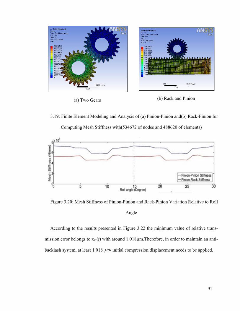
91
(a) Two Gears
(b) Rack and Pinion
3.19: Finite Element Modeling and Analysis of (a) Pinion-Pinion and(b) Rack-Pinion for
Computing Mesh Stiffness with(534672 of nodes and 488620 of elements)
Figure 3.20: Mesh Stiffness of Pinion-Pinion and Rack-Pinion Variation Relative to Roll
Angle
According to the results presented in Figure 3.22 the minimum value of relative trans-
mission error belongs to x12(t) with around 1.018µm.Therefore, in order to maintain an anti-
backlash system, at least 1.018 m initial compression displacement needs to be applied.

92
Table 3.2: Parameters used in simulation
Parameter Value Parameter Value
Applied torque, T(N/m) 24 0.76
Applied force on rack, F(N)
0 ( / )m
k N mm 523000
Rotational speed of pin-ions, n (rpm) 1000 0
b 0.9494
Initial compression dis-placement between mated
pinions, 1
)( m 5 1
b 0.08264
Damping coefficient,
1 2( . / )c c N s m 1000 2
b -0.03548
According to Eq. (3.14), the approximated amount of compression displacement is 1.15
m and if the modification of mesh stiffness were not applied, the minimum compression
displacement value would be 0.95 m , which is less.
Thus, the method suggested in this work to evaluate the approximate required initial
compression displacement is effective and simple and does not need lengthy and tedious
simulation.
In order to investigate the alternation of transmission error under tooth separation, the
initial compression displacement was reduced to 0.9 m to activate the nonlinearity in the
equation of motion associated with tooth separation. Figure 3.22 shows the transmission
error associated with initial compression displacement of 5 m and 0.9 m , respectively.
This figure indicates that the absolute value of transmission error increases as the initial
compression crosses the limit.

93
(a) (b)
(c) (d)
(e) (f)
(g) (h)
(i) (j)
Figure 3.21: Time Response and FFT of Transmission Errors:
(a,b) 12( )x t , (c,d) 13( )x t , (e,f) 24 ( )x t , (g,h) 34( )x t and (i,j) T.E.

94
Figure 3.22: Transimision Error Under the Linear (1
5 m ) and Nonlinear Region
(1
0.9 m )
Since the preload and initial compression displacement are in direct relation, then, by in-
creasing the preload the absolute value of transmission error will be reduced in the nonline-
ar region.
3.8 Conclusion
In this chapter, the conceptual design of a new CNC gantry machine with (LL) LLRR
kinematic configuration and its advantages was presented. According to the design of this
new type of gantry machine, the new feed drive motion (double motion mechanism) was
designed. In response to the problem with the rack and pinion used in the double motion
mechanism for removing backlash, a new concept of a double motion mechanism with an
anti-backlash device with a combination of three gears and one rack was introduced. The
advantages of the new double motion mechanism were explained. A nonlinear dynamic
analysis of the new anti-backlash system was presented to gain insight into the system’s
dynamic behavior. The validity of the concept of eliminating backlash was examined with
Motion Analysis of Solidworks CAD software. The mesh stiffness of mated gears and rack-
pinion was evaluated with the finite element method and a motion equation was solved.

95
Assuming that the gear and rack teeth are rigid and static transmission error is negligible,
the total transmission error of the new mechanism is zero, which is one of the more signifi-
cant features of this system. The minimum amount of preload at which the system remains
anti-backlash during operation was estimated. This depends on applied torque, external
load on the rack and varied mesh stiffness behavior. Total system transmission error was
obtained by solving the differential equation of motion using the Runge-Kutta method.
Finally, it is expected that the proposed mechanism will find numerous applications in
industry, such as industrial robots and precision machine tools, due to its low transmission
error and low preload.
Further development and investigations of the relative advantages of this new mecha-
nism through experimentation could be a subject of future research. The structural design
steps of the new type of CNC gantry machine are discussed in the next chapter

96
4.1 Introduction
To design the new type of CNC gantry machine, designer expertise is required in the ini-
tial stage. The different designs for the new CNC gantry machine proposed are introduced
in this section according to designer experience. Following the expert design step, the addi-
tional improvement process of the final design using FEM software will be discussed.
The first design introduced is based on a new system with a double motion mechanism.
As discussed in Section 3.3, there are two types of double motion mechanism. The first
type is designed based on a rack and pinion and the second type is based on a ball screw.
In this chapter, the second type of double motion mechanism is introduced. In this system,
the motions of the gantry and worktable are independent. Actually, in the new double mo-
tion feed drive system the worktable and gantry motions are dependent during machining
but independent if workpiece set-up is required. Hence, the double motion mechanism
based on the rack and pinion system cannot fit this motion requirement.
4.2 Double Motion Mechanism Based on a Ball Screw System
For the second type of double motion mechanism, the ball screw system is proposed.
Hence, the gantry and worktable of the CNC machine can be moved separately by this sys-
tem. The U-axis has been added to the machine and consequently, the gantry moves on the
U-axis and the worktable moves on the X-axis. The gantry CNC machine controller must
CHAPTER 4
4 STRUCTURAL DESIGN OF THE GANTRY MACHINE TOOL

97
control both independently. In this stage, many industrial applications require flexible feed
drive system such as worktable and gantry move simultaneously or individually. As a re-
sult, we decided to use double motion based on independent system. Hence the most im-
portant achievement is the combination of three types of CNC gantry machine into one ma-
chine with the double motion mechanism based on a ball screw system, as shown in Fig-
ure 4.1.
Figure 4.1: The combination of 3 types of CNC gantry machine with a double motion
mechanism
The new CNC gantry machine can be used for three kinds of application. The “fixed
gantry,” “fixed worktable,” and “moving gantry and worktable” together form the combi-
The Ball Screw System The Worktable is on the X-axis
The Beas column of the Gantry (U-axis)

98
nation of three types of CNC gantry machine. These three application types are provided by
the new double motion system based on a ball screw. Therefore, the total longitudinal mo-
tion of the machine has been converted to the X- and U-axes. The double motion mecha-
nism based on a ball screw system has two characteristics:
1. The motion of the gantry is independent of the worktable and vice versa. With this
advantage, the machine can employ three types of CNC gantry together (fixed gantry, fixed
worktable and double motion system). It is suitable for academic use by different research-
ers in machining processes using three types of CNC gantry machine.
2. The gantry and worktable can be controlled by two axes (X & U) separately. The
CNC gantry machine’s kinematic configuration is LLLLRR (four separate linear motions
and two rotational motions relative to a standard CY spindle), meaning that the CNC gantry
machine needs to have a six-axis CNC controller.
4.3 Gradual Design of a Gantry Machine Tool Using the Ball Screw System
In this section, the gradual gantry design including the design of the structure, axis parts,
gantry, crossbeam, feed drive motion and other parts, is investigated. The final design has
been chosen for the following process that is utilized to further improve the design using
well-known scientific methods.
Regarding the design of a CNC machine gantry, two initial, different design methods for
a gantry are introduced. One is the crane design method, which is normally used for design-
ing cranes (discussed in chapter 2). The second is the common gantry design method, using
normal and slant crossbeams. The gantry crane, columns and crossbeam, main structure,
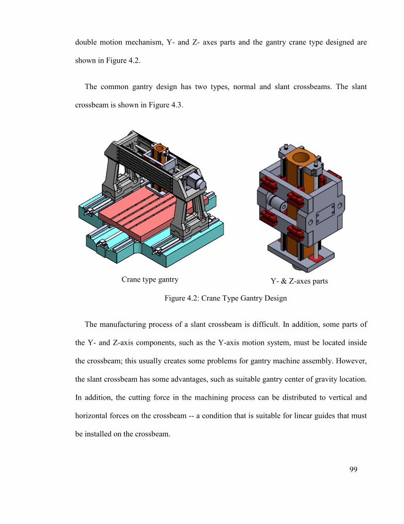
99
double motion mechanism, Y- and Z- axes parts and the gantry crane type designed are
shown in Figure 4.2.
The common gantry design has two types, normal and slant crossbeams. The slant
crossbeam is shown in Figure 4.3.
Crane type gantry
Y- & Z-axes parts
Figure 4.2: Crane Type Gantry Design
The manufacturing process of a slant crossbeam is difficult. In addition, some parts of
the Y- and Z-axis components, such as the Y-axis motion system, must be located inside
the crossbeam; this usually creates some problems for gantry machine assembly. However,
the slant crossbeam has some advantages, such as suitable gantry center of gravity location.
In addition, the cutting force in the machining process can be distributed to vertical and
horizontal forces on the crossbeam -- a condition that is suitable for linear guides that must
be installed on the crossbeam.

100
Figure 4.3: Gantry with a Slant Crossbeam
Actually, it is easy to manufacture the normal crossbeam with this method, but the gan-
try’s center of gravity must be improved by applying design modifications. This method is
a common, standard approach, which is why it was chosen to design the new CNC gantry.
Based on this discussion, the normal crossbeam is used in the design of the new CNC gan-
try machine. The gantry with a normal crossbeam is shown in Figure 4.4.
The normal crossbeam has a key disadvantage as discussed previously. The centers of
gravity of the spindle carriage and holder are far from the gantry’s center of gravity. This
will cause a problem for linear motion guides installed under the gantry columns that will
probably get damaged during operation because of the cutting forces produced by the cut-
ting tools.
Slant Crossbeam
Gantry column Spindle Carriage
Y axis Motion system
Gantry is on the U-axis
The worktable is on the X-axis
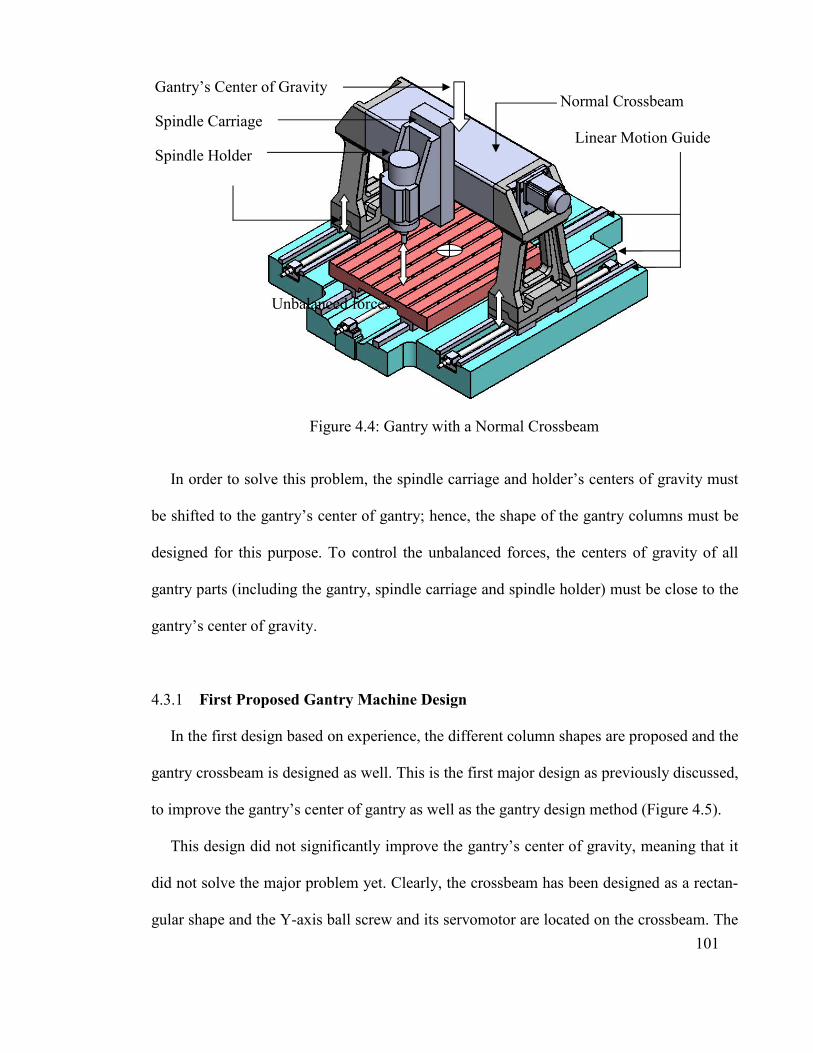
101
Figure 4.4: Gantry with a Normal Crossbeam
In order to solve this problem, the spindle carriage and holder’s centers of gravity must
be shifted to the gantry’s center of gantry; hence, the shape of the gantry columns must be
designed for this purpose. To control the unbalanced forces, the centers of gravity of all
gantry parts (including the gantry, spindle carriage and spindle holder) must be close to the
gantry’s center of gravity.
4.3.1 First Proposed Gantry Machine Design
In the first design based on experience, the different column shapes are proposed and the
gantry crossbeam is designed as well. This is the first major design as previously discussed,
to improve the gantry’s center of gantry as well as the gantry design method (Figure 4.5).
This design did not significantly improve the gantry’s center of gravity, meaning that it
did not solve the major problem yet. Clearly, the crossbeam has been designed as a rectan-
gular shape and the Y-axis ball screw and its servomotor are located on the crossbeam. The
Normal Crossbeam
Linear Motion Guide
Gantry’s Center of Gravity
Spindle Carriage
Spindle Holder
Unbalanced forces

102
Y-axis part comprises the body and standard components such as spindle carriage linear
blocks and spindle holder with two main components, the body and holder. The spindle
holder’s linear guide is installed onto the spindle carriage and the spindle holder servomo-
tor is installed on top of the spindle carriage body. The initial design of the new CNC gan-
try machine is shown in Figure 4.5. In the first design, three servomotors support the X-
and U-axes’ (worktable and gantry) feed drive motions. They connect to the ball screws
using flexible couplings.
Figure 4.5: The First Gantry Machine Design Proposed
Although the feed drive motions of the gantry and worktable parts are supported by this
system, two other feed drive motions (Y- and Z-axes) are supported by a belt in this design.
Usually, for better performance the servomotor must support the ball screw directly via
Y-axis Ball screw
U-axis Ball screw
U-axis Ball screw
X-axis Ball screw
Gantry’s Center of Gravity
Servomotor Bracket

103
flexible coupling. The servomotors’ brackets of X- and U-axes were designed and installed
onto the structure. The gantry’s center of gravity was still not acceptable and had to be im-
proved in the next design. Additional changes to the column shape should perhaps improve
the design for enhanced performance. The spindle carriage and spindle holder are shown in
Figure 4.6, with standard components such as linear guides and ball screw selected and
added to the design. The Y- and Z-axis parts of the CNC gantry machine are clearly visible.
Figure 4.6: The Y- and Z-axis parts
4.3.2 Second Proposed Gantry Machine Design
In this CNC gantry machine design, two important changes are applied.
Z-axis ball screw
Spindle Holder
Spindle
Z-axis Linear Guide
The Z-axis motion
Transfer via Belt
Spindle
Carriage body

104
1. To improve the gantry’s center of gravity, the shape of the columns has been changed
(Figure 4.7). Changing the columns’ shape improved the position of the gantry’s center of
gravity, whereby the center of gravity has shifted to the center of the gantry.
2. As discussed in section 4.2, to incorporate three types of CNC gantry machine in one
machine, the gantry must be able to move nearly the entire structure length. Hence, the ma-
chine structure has been modified for this purpose. The overall dimensions of the CNC
gantry machine and machining space have been finalized in this design.
Figure 4.7 shows the second design of the new CNC gantry machine.
4.3.3 Third Proposed Gantry Machine Design
In the third design, more modifications have been done to improve the gantry’s center of
gravity location. Most changes were done to the machine gantry. This design is the final
modification of the CNC gantry machine using designer experience and is shown in Fig-
ure 4.8.
In this design, additional changes have been applied to the gantry components, such as
columns and crossbeam, for easy manufacturing and assembly. For example, the Y-axis
servomotor was placed inside the gantry for easy assembly; with this modification, the Y-
axis servomotor can be installed to the ball screw directly using flexible coupling. The Z-
axis servomotor bracket was designed, which can also be installed to the ball screw directly
by flexible coupling. In this design the gantry’s center of gravity has nearly shifted to the
center of the gantry. It can be seen in Figure 4.9 that the first and final designs are compa-
rable. The next steps in the design process entail modifications based on the dynamic and
static design requirements using finite element analysis.
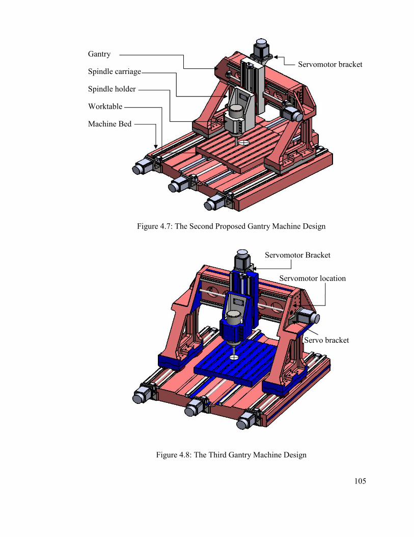
105
Figure 4.7: The Second Proposed Gantry Machine Design
Figure 4.8: The Third Gantry Machine Design
Servomotor location
Servo bracket
Servomotor Bracket
Gantry
Spindle carriage
Spindle holder
Worktable
Machine Bed
Servomotor bracket
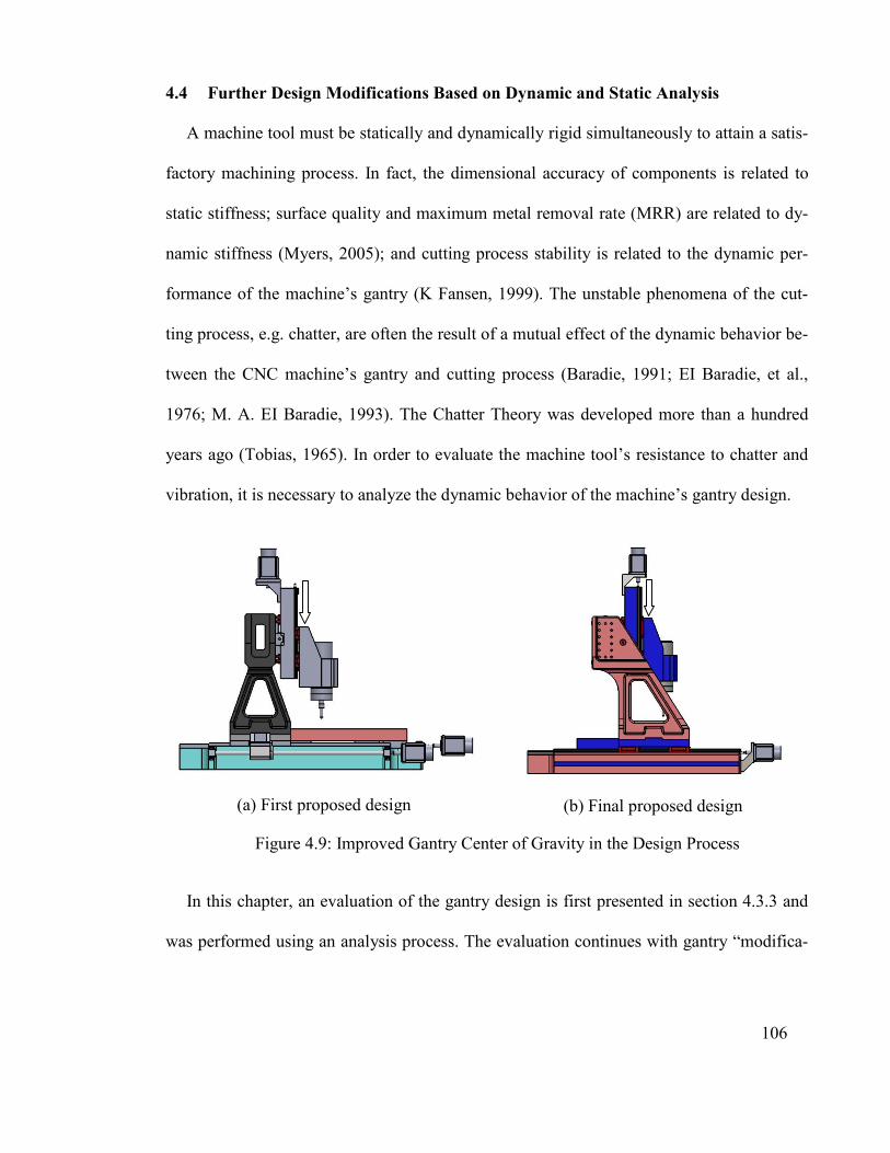
106
4.4 Further Design Modifications Based on Dynamic and Static Analysis
A machine tool must be statically and dynamically rigid simultaneously to attain a satis-
factory machining process. In fact, the dimensional accuracy of components is related to
static stiffness; surface quality and maximum metal removal rate (MRR) are related to dy-
namic stiffness (Myers, 2005); and cutting process stability is related to the dynamic per-
formance of the machine’s gantry (K Fansen, 1999). The unstable phenomena of the cut-
ting process, e.g. chatter, are often the result of a mutual effect of the dynamic behavior be-
tween the CNC machine’s gantry and cutting process (Baradie, 1991; EI Baradie, et al.,
1976; M. A. EI Baradie, 1993). The Chatter Theory was developed more than a hundred
years ago (Tobias, 1965). In order to evaluate the machine tool’s resistance to chatter and
vibration, it is necessary to analyze the dynamic behavior of the machine’s gantry design.
(a) First proposed design
(b) Final proposed design
Figure 4.9: Improved Gantry Center of Gravity in the Design Process
In this chapter, an evaluation of the gantry design is first presented in section 4.3.3 and
was performed using an analysis process. The evaluation continues with gantry “modifica-

107
tion” followed by a “selection” process of the best gantry design. The analysis process is
presented as follows:
A) Modal analysis of the gantry is carried out in order to extract the natural fre-
quencies and mode shapes.
B) Harmonic analysis of the gantry is done according to the cutting process per-
formance, which is defined for the machine design (L.N, 2009).
C) The gantry is statically analyzed to extract the maximum deformation under
the weight and cutting force.
4.4.1 Dynamic Analysis of the Gantry
Sufficient gantry stiffness and damping lead to a stable cutting process and the perfor-
mance is achievable by dynamically modifying the machine tool (Zhang, 1996).
In the modification process using modal analysis, the following procedure was done se-
quentially.
- The gantry’s 3D design was converted into simulation software format
- The dynamic behavior of the gantry was evaluated by modal analysis; the first natural
frequency of the gantry was extracted in this step.
- The results were compared with the initial requirement of 200 Hz natural frequency.
- The modification process for the gantry was performed based on the modal analysis
results.
- The gantry was statically analyzed.
In the modification process, around 12,000 rpm (200 Hz natural frequency) for the ma-
chine spindle and 10-micron spindle tip accuracy are requirements that must be achieved in

108
the dynamic analysis step. Other machine requirements, such as what kind of materials can
be machined or the machine’s material removal rate (MRR) value are discussed in the static
analysis step. The design modification process flow chart is shown in Figure 4.10
Figure 4.10: Design Modification Process Flow Chart
The entire analysis process was done in ANSYS (engineering simulation software) by
finite element method. In order to make a finite element model, a three dimensional model
of machine’s gantry with ANSYS Workbench has been under consideration. The three di-
mensional model with SolidWorks software is executed. The model is exported to ANSYS
Workbench and the necessary input data as material properties like modulus of elasticity,
Poison ratio and density is applied. Then, elements of the model are made under Solid ele-
ment. This model has 85985 elements and 154081 nodes. Relevant boundary conditions are
applied on the earth connection of the gantry. Finally, modal analysis is performed to ob-
tain natural frequencies of the gantry. During analysis, the total weight of the gantry was
417 kg; each column was 93.55 kg, the crossbeam was 118 kg and the spindle carriage and
holder were 118 kg. The third gantry design is shown in Figure 4.11.
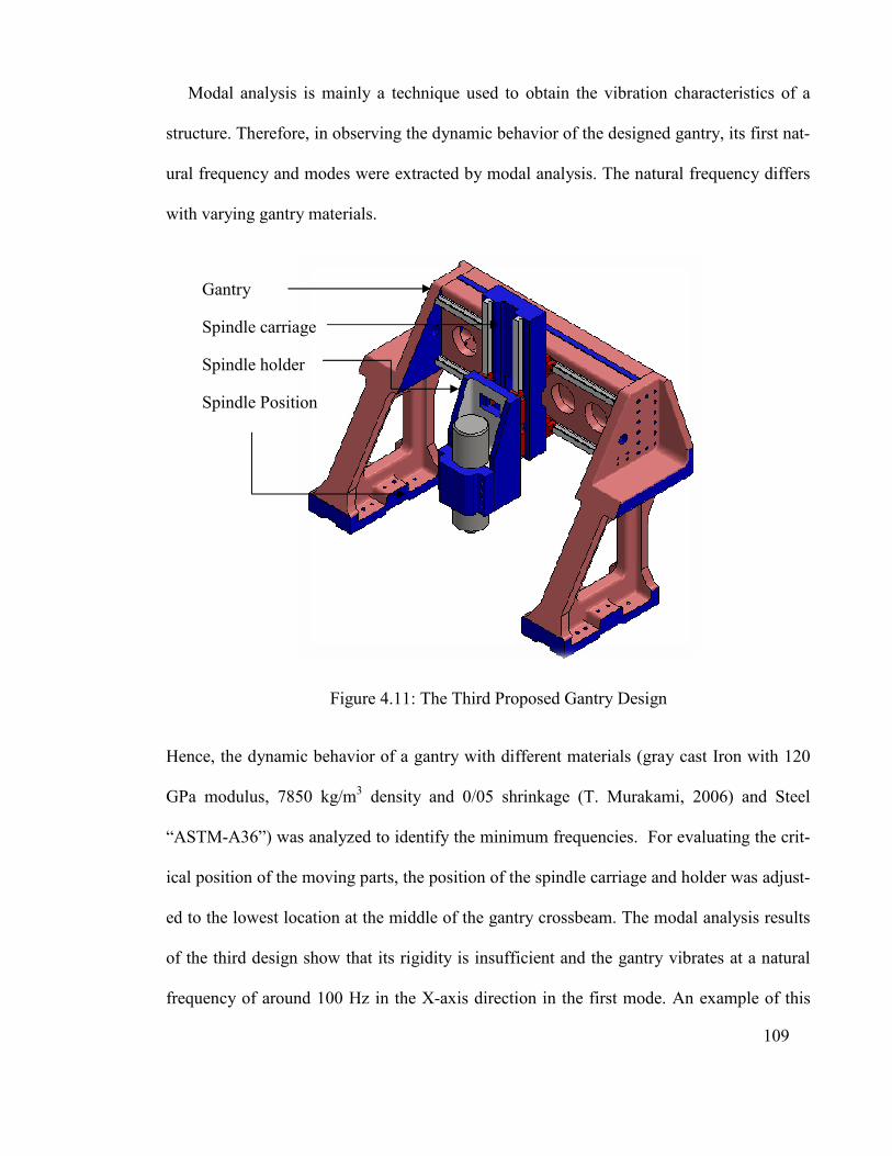
Modal analysis is mainly a technique used to obtain the vibration characteristics of a
structure. Therefore, in observing the dynamic behavior of the designed gantry, its first na
ural frequency and modes were extracted by
with varying gantry materials.
Figure
Hence, the dynamic behavior of a gantry with different materials (gray cast Iron with 120
GPa modulus, 7850 kg/m
“ASTM-A36”) was analy
ical position of the moving parts, the position of the spindle carriage and holder was adjus
ed to the lowest location at the middle of the gantry crossbeam. The modal analysis results
of the third design show that its rigidity is insufficient and the gantry vibrates at a natural
frequency of around 100 Hz in the X
Gantry
Spindle carriage
Spindle holder
Spindle Position
Modal analysis is mainly a technique used to obtain the vibration characteristics of a
structure. Therefore, in observing the dynamic behavior of the designed gantry, its first na
ural frequency and modes were extracted by modal analysis. The natural frequency differs
with varying gantry materials.
Figure 4.11: The Third Proposed Gantry Design
behavior of a gantry with different materials (gray cast Iron with 120
GPa modulus, 7850 kg/m3 density and 0/05 shrinkage (T. Murakami, 2006
A36”) was analyzed to identify the minimum frequencies. For evaluating the cri
ical position of the moving parts, the position of the spindle carriage and holder was adjus
ed to the lowest location at the middle of the gantry crossbeam. The modal analysis results
third design show that its rigidity is insufficient and the gantry vibrates at a natural
frequency of around 100 Hz in the X-axis direction in the first mode. An example of this
109
Modal analysis is mainly a technique used to obtain the vibration characteristics of a
structure. Therefore, in observing the dynamic behavior of the designed gantry, its first nat-
modal analysis. The natural frequency differs
: The Third Proposed Gantry Design
behavior of a gantry with different materials (gray cast Iron with 120
T. Murakami, 2006) and Steel
For evaluating the crit-
ical position of the moving parts, the position of the spindle carriage and holder was adjust-
ed to the lowest location at the middle of the gantry crossbeam. The modal analysis results
third design show that its rigidity is insufficient and the gantry vibrates at a natural
axis direction in the first mode. An example of this

110
modal analysis evaluation is shown in Figure 4.12 and the modal analysis results for two
different gantry materials (gray cast Iron and Steel) are shown in Figure 4.13 (a, b). The
results indicate that the minimum natural frequency of a gantry with steel is better than cast
iron, but still, neither meets the initial design target of 200 Hz.
Figure 4.12: Modal Analysis Results for the Third Design
The dynamic analysis process must be resumed because the result is not acceptable. For
this reason, more design modifications are required to meet the design requirements.
Various column and crossbeam shapes have been proposed to improve the gantry’s nat-
ural frequency. Many changes have also been made to the columns and crossbeam in the
modification process to enhance the natural frequency (Figure 4.14). In order to increase
the natural frequency it is necessary to enhance the stiffness of the structure. Increasing the
stiffness requires enlarging the cross selection area. In contrast, increasing the area leads to

111
greater structure mass, which consequently decreases the structure’s natural frequency.
Therefore, increasing the stiffness shall be conducted bearing in mind the dynamic struc-
ture and its mode shape. The most significant parts of the structure that have the highest
impact on natural frequency should be identified prior to applying changes.
Frequency Modes (a) Using Cast Iron
Frequency Modes (b) Using Steel
Figure 4.13: Modal Analysis Results for the Third Design
With respect to the first shape mode of the structure, the most effective part for enhanc-
ing the stiffness and natural frequency is the column’s cross section. As seen in
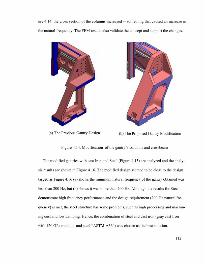
112
ure 4.14, the cross section of the columns increased -- something that caused an increase in
the natural frequency. The FEM results also validate the concept and support the changes.
(a) The Previous Gantry Design
(b) The Proposed Gantry Modification
Figure 4.14: Modification of the gantry’s columns and crossbeam
The modified gantries with cast Iron and Steel (Figure 4.15) are analyzed and the analy-
sis results are shown in Figure 4.16. The modified design seemed to be close to the design
target, as Figure 4.16 (a) shows the minimum natural frequency of the gantry obtained was
less than 200 Hz, but (b) shows it was more than 200 Hz. Although the results for Steel
demonstrate high frequency performance and the design requirement (200 Hz natural fre-
quency) is met, the steel structure has some problems, such as high processing and machin-
ing cost and low damping. Hence, the combination of steel and cast iron (gray cast Iron
with 120 GPa modulus and steel “ASTM-A36”) was chosen as the best solution.

113
Figure 4.15: Final Analysis Results
Therefore, the crossbeam material was converted to steel for this purpose. The modal anal-
ysis of the new combination of gantry materials performed is shown in Figure 4.17.
The analysis results of the new combination of gantry materials are shown in Fig-
ure 4.18. The modal analysis results indicate that the design target (200 Hz) was achieved.
However, the modification process caused an increase in the gantry’s weight.
The reason steel was applied in the crossbeam is that steel weights less than cast Iron
and therefore reduces the weight associated with the system and increases the natural fre-
quency. On the other hand, decreasing the weight of the crossbeam rather than the columns

114
has greater effect on increasing the natural frequency since in the first mode the crossbeam
has more vibration than the columns.
Frequency Modes
(a) Modal Analysis Results for the Modified Gantry using Cast Iron
Frequency Modes
(b) Modal Analysis Results for the Modified Gantry using Steel
Figure 4.16: Modal Analysis Results for the Gantry Modification Process
(Cast Iron and Steel)

115
A major challenge in gantry design is the changing position of the moving elements,
such as the spindle carriage and holder. The dynamic behavior of the gantry will be affect-
ed by the different positions, as the gantry’s mass distribution and stiffness change.
Figure 4.17: Modal Analysis Results of the Gantry using a Combination of Cast Iron
and Steel
Frequency Modes
Figure 4.18: Modal Analysis Results of the Gantry using a Combination of
Cast Iron and Steel

116
To investigate the dynamic behavior of the gantry relative to the different moving part
positions, two new spindle carriage and holder positions were evaluated by modal analysis.
Two positions for the moving parts (spindle carriage and spindle holder) were selected
to evaluate the dynamic behavior of the gantry in this case. The spindle carriage is extreme
left side of middle of the gantry crossbeam when the spindle holder is at the end of the
spindle carriage. The modal analysis of the gantry when the moving parts are on the ex-
treme left side of the crossbeam is shown in Figure 4.19 and the modal analysis results for
the extreme left side position of the moving parts are shown in Figure 4.20. The results
show that the gantry’s minimum natural frequency did not change significantly, but the
minimum frequency occurred when the Y-axis was at the extreme left of the crossbeam.
Although the first natural frequency almost did not change in this position, the other fre-
quency modes increased significantly.
The modal analysis for the middle position of the gantry crossbeam when the spindle
holder is at the middle of the spindle carriage is shown in Figure 4.21 and the analysis re-
sults are shown in Figure 4.22. According to the modal analysis results, the first natural
frequency in the middle position increased significantly, meaning that the moving parts
(spindle carriage and holder) could help increase the crossbeam stiffness in the middle po-
sition.
As seen in Figure 4.22, the gantry’s natural frequencies in the middle gantry crossbeam
position are higher in all frequency modes. Therefore, the natural frequencies of all posi-
tions, even the critical gantry position that was selected at the first, are higher than the de-
sign requirement of 200 Hz.

117
Figure 4.19: The Extreme Left Positions of the Spindle Carriage and Holder
Frequency Modes
Figure 4.20: Modal Analysis Results for the Extreme Left Position of the Moving Parts

118
Figure 4.21: Modal Analysis of the Gantry when the Spindle Holder is in the Middle of
the Spindle Carriage
Frequency Modes
Figure 4.22: Modal Analysis Results for the Gantry with New
Moving Part Positions

119
4.4.2 Static Analysis of the Modified Gantry
To identify the static behavior of the gantry, two evaluations were performed. The total
deformation of the gantry under its total weight, which increased during modification, was
extracted via static analysis. In this process, the total gantry weight was applied onto the
middle of the gantry crossbeam. The total deformation under the weight is shown in Fig-
ure 4.23.
Figure 4.23: Total Deformation under the Weight
Figure 4.23 shows the total crossbeam deformation under the weight acquired in the red
area, which is 6.3662e-4 mm -- less than the minimum required error of 10 µm.
The standard, high-speed CNC machine spindle was chosen. It has 3.3 N-m torque and
more than 12,000 rpm. An end mill was used for cutting at high-speed machining to calcu-

120
late cutting force. The cutting force generated by spindle torque can be calculated. An end
mill with 8 mm diameter served as the cutting tool in this process. The amount of cutting
force on the edge of the end mill based on the torque equation (M=F*r) was 825 N. The
cutting pressure in a milling operation can be obtained from the (KS=F/A) equation and
Figure 4.24. For calculating KS, the cross section of a milling chip was selected (1 mm
depth and 0.3 mm feed rate, then A = 0.3 mm2) to find the maximum cutting pressures that
can be obtained from the spindle torque with the selected tool. If the force already calculat-
ed is (F=825 N), then the amount of KS will be 2750 N/mm2. According to this infor-
mation, the type of material that can be machined with this tool is obtained as per Fig-
ure 4.24, hence the selected tool is able to machine steel (ST 34-37).
The selected spindle can clamp 4-16 mm diameter and different end mill sizes. This cal-
culation method can be used for various end mill sizes.
The cutting speed (Eq. 4.1) according to 8 mm diameter end mill and 12,000 RPM spin-
dle speed was 301.44 m/min. According to KS (2750 N/mm2) and (A= 0.3 mm2) the spin-
dle must be able to produce 4.144 kW of power using (Eq. 4.2) for a machining operation
in this case. However, the selected spindle can produce 6 kW of power, so it is easily capa-
ble of this cutting operation.
� =�∗�∗�
���� (4.1)
P =�∗��∗�
����� (4.2)
In order to evaluate the gantry behavior under the cutting force of finishing steel materi-
al, the total amount of force must be multiplied by a 1.2 safety factor.

121
Figure 4.24: Material Cutting Pressures (Graham, 2008)
This amount of force (F=990N) is located on the tip of the end mill and the undesirable de-
formation under cutting force is identified via static analysis (Figure 4.25).
As shown in Figure 4.25, the maximum structure deformation under the maximum force
produced by the spindle (when the spindle holder is in critical position) is 0.0099 mm.
Thus, the expected accuracy of 10 microns is achievable in critical condition.
4.4.3 Harmonic Analysis
In the next step, the total amount of deformation when the gantry vibrates under cutting
force of F=825 N must be identified using harmonic analysis. 300 Hz frequency was evalu-
ated to observe the maximum gantry deformation during vibration. Furthermore, the exist-

122
ing cutting force of F=825 N was applied to the spindle tip for analysis. The harmonic
analysis result is shown in Figure 4.26.
Figure 4.25: Maximum Deformation of the Gantry under Cutting Force
The frequency response from the harmonic analysis is shown in Figure 4.27. Evidently,
the maximum deformation (nearly 150 microns) of the spindle tip occurred when the spin-
dle was rotating at nearly 12600 rpm; however, at less than 11530 rpm the maximum de-
formation was 10 microns. Hence, the required 10micron accuracy for the gantry machine
can be achieved at around 11530 rpm spindle speed.
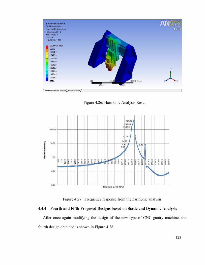
123
Figure 4.26: Harmonic Analysis Resul
Figure 4.27 : Frequency response from the harmonic analysis
4.4.4 Fourth and Fifth Proposed Designs based on Static and Dynamic Analysis
After once again modifying the design of the new type of CNC gantry machine, the
fourth design obtained is shown in Figure 4.28.

124
Figure 4.28: The Fourth Proposed Design in the Modification Process
Since the gantry weight increased during the modification process, a new crossbeam was
designed to reduce the weight. This design reduced the gantry’s weight by up to 3.8%. Fig-
ure 4.29 shows the fifth proposed design (lightweight gantry).
Figure 4.29 : The Fifth Proposed Design (lightweight gantry)
Both last two designs satisfy the design requirement. The fifth design is lighter than the
fourth design but the fifth design has been shown lower natural frequency than the fourth

125
design. In addition, the fifth design is more difficult to be manufactured using the available
facilities on prototyping process. However, in selection process some of the important crite-
ria of the existing designs will be evaluated via the proper method.
4.5 Best Design Selection
Five gantry designs have been developed based on experience and modification process-
es. Each step of the process focused on one or two gantry design criteria, such as stiffness
or natural frequency. There are other criteria, including light weight and manufacturing cost
that cannot be achieved at the same time in the design process but are nonetheless im-
portant to selecting the best option. There are several scientific methods to find the ideal
option among several designs with different criteria.
Figure 4.30 illustrates the design obtained from the gradual design and modification
process. In the selection process for the best gantry design, the four main criteria consid-
ered were manufacturing cost, natural frequency, the total deformation of each gantry under
its weight and cutting force and weight.
4.5.1 Cost Evaluation
Cost is an important factor in the selection process. To evaluate the cost of the obtained
designs, four cost sources (modeling, casting, machining and assembling) were defined
based on existing experience and manufacturers’ quotations, such as casting cost (cast iron
per Kg), modeling cost (cost of patterns) and casting process, machining and assembly cost.
The costs were estimated by industrial experts, as presented in Table 4.1.

126
1. The First Design
2. The Second Design
3. The Third Design
4. The Fourth Design
5. The Fifth Design
Figure 4.30: Five Proposed Designs

127
Table 4.1: Cost Estimation Results for Five Gantry Designs
Model5 Model4 Model3 Model2 Model1 Parameters
3100$ 2800$ 3000$ 2500$ 2100$ Modeling
1161$ 1224$ 765$ 685$ 492$ Casting/Kg
6000$ 6500$ 5800$ 5900$ 4500$ Machining
600$ 500$ 400$ 400$ 350$ Assembly
10861$ 11024$ 9965$ 9485$ 7442$ Total Cost
4.5.2 Evaluation of Gantry Designs
The initial gantry design evaluation was conducted based on designer experience and anal-
ysis. An attempt was made for each configuration to offer unique characteristics with re-
spect to performance indices. The initial results of static and dynamic analysis evaluations
as well as prototyping costs are shown in Table 4.2
Table 4.2: Performance Index Values for the Five Gantry Models
Model 5 Model 4 Model 3 Model 2 Model 1
4.41 3.60 8.53 6.32 6.63 Deformation (µm)
250.47 286.69 135.5 157.54 215.1 1th N.F.
307.71 303.17 202.98 194.54 216.49 2ed N.F.
441.69 479.38 320.23 370.24 403.29 3rd N.F.
507.22 631.56 368.08 381.87 525.7 4th N.F.
473.5 492.6 292.1 244 273.2 Mass (kg)
1088.75
11031.5
9930.25
9410
7633
Approximated Manu-
facturing Cost (Unit)
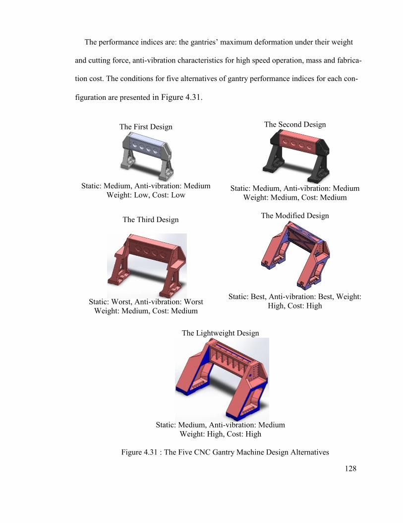
128
The performance indices are: the gantries’ maximum deformation under their weight
and cutting force, anti-vibration characteristics for high speed operation, mass and fabrica-
tion cost. The conditions for five alternatives of gantry performance indices for each con-
figuration are presented in Figure 4.31.
The First Design
Static: Medium, Anti-vibration: Medium
Weight: Low, Cost: Low
The Second Design
Static: Medium, Anti-vibration: Medium
Weight: Medium, Cost: Medium
The Third Design
Static: Worst, Anti-vibration: Worst
Weight: Medium, Cost: Medium
The Modified Design
Static: Best, Anti-vibration: Best, Weight:
High, Cost: High
The Lightweight Design
Static: Medium, Anti-vibration: Medium
Weight: High, Cost: High
Figure 4.31 : The Five CNC Gantry Machine Design Alternatives

129
Because there are many criteria affecting the ultimate selection, it is indeed difficult to
choose among these five candidate designs. This problem leads to using special methods
that help find out which candidate is more appropriate and appealing. In the next chapter,
the MCDM (Multi-criteria decision making) is introduced and exploited to select the best
overall design.
4.6 Conclusion
In this section the double motion mechanism was converted from a rack and pinion to a
ball screw system. The three gradual designs of the new type of CNC gantry machine were
presented. All CNC gantry machine components were designed and completed in the ma-
chine assembly. Most changes were dependent on the gantry columns. Several different
machine designs were evaluated to improve the machine design. The third design of the
new CNC gantry machine was presented and enhanced center of gravity was found.
To evaluate the gantry’s behavior and modification with desired characteristics, modal
analysis was performed. The natural frequency of the gantry was 102.36 HZ and the gan-
try’s frequency was 131.95 Hz when the material was changed to steel. The results showed
that the gantry was improving. Modification was also done to increase stiffness. For this,
the minimum natural frequency of the gantry was increased slightly, to more than 200 Hz.
This gantry modification process increased its weight. The results indicate that the Z-axis
position had no significant effect on the gantry’s dynamic behavior. The range of machin-
ing materials and cutting force was calculated for the selected spindle. According to the
static analysis results, the cutting force did not have any negative effect on machining pre-
cision. The harmonic results show that deformation was around 10 microns at the spindle
tip at 11530 rpm. The fourth proposed design of a new CNC gantry machine was patented

130
(S. R. Besharati, et al., 2013) as a special gantry machine of three different types. The
fourth and fifth designs were proposed and the fifth design was a lightweight gantry, with
gantry weight reduction by up to 3.8%.
As pointed out, due to the difficulty in selecting the best design, it was necessary to em-
ploy the MCDM method to discover the best overall design. In the next chapter, the
MCDM is introduced and two methods, AHP and PEG-MCDM, are used to help obtain the
best overall design. The optimum gantry selection process in light of the different designs
and the optimization of the ultimately chosen one will be discussed in the next chapter as
well.

131
5.1 Introduction
The gantry design is an important part of the CNC gantry machine tool, as the gantry
plays a crucial role in supporting the spindle as well as influencing the gantry’s static and
dynamic characteristics. This is reflected in the final machining precision and ultimate al-
lowable cutting speed and feed rate.
In this section, selecting the best gantry alternative using Multi-Objective design is con-
sidered through the analytical hierarchy process (AHP) and PEG-MCDM method. The ob-
jectives include the maximum static deformation of the gantry, the first four natural fre-
quencies, mass and fabrication cost. The AHP method is applied to quantify the signifi-
cance of each criterion according to experts’ judgment. The five proposed gantry configu-
ration designs are selected based on experts’ experience and the engineering modification
process.
Upon selecting the best among five proposed designs, the multi-objective genetic algo-
rithm is employed to further enhance the performance indices. However, due to the com-
plexity involved in automatic cost evaluation, these indices are not considered during the
optimization process. The optimization results offer several solutions. The PEG-MCDM is
used to select the best candidate and the final solution offers good static, dynamic and
weight performance.
CHAPTER 5
5 OPTIMUM GANTRY DESIGN USING MULTI-CRITERIA DECI-
SION MAKING (MCDM) METHOD AND MULTI-OBJECTIVE
STRUCTURAL OPTIMIZATION OF GANTRY

132
5.2 Optimum Gantry Design using AHP and PEG-MCDM
In practice, gantry design is a multi-criteria decision making problem aimed to achieve
the ultimate design that exhibits higher stiffness, less deflection, low cost and light weight
performance (Ayağ, et al., 2006). Improper machine design and selection may cause ineffi-
cient design with low performance and weak competitive capabilities. Due to conflict be-
tween the design criteria, selecting the best solution without using quantitative methods is
not appropriate. Several MCDM methods introduced by many researchers can be used suc-
cessfully in machine tool design selection (G-H Tzeng, 2011). A number of the MCDM
(Multi-Criteria Design Making) methods are based on the Decision Maker's (DM) prefer-
ence, which stems from the DM’s wisdom and experience.
5.2.1 Analytical Hierarchy Process (AHP)
The Analytical Hierarchy Process (AHP) proposed by Saaty (Saaty, 1980) is based on a
pair-wise comparison of alternatives or criteria according to a DM’s judgment. Ease and
applicability of this method lead to its exploitation in many diverse applications, especially
in machine tool selection. After obtaining the evaluation matrix based on the DM’s prefer-
ence, a consistency test must be performed to ensure consistent results. Finally, this method
reveals the weight of each alternative or criterion, which may later be applied for the deci-
sion making process.
In order to convert the judgment of a DM to a corresponding numerical value, Table 5.1
serves as a guide.

133
The AHP method must be used separately for each group of criteria or alternatives that
are on the same level. Thereafter, an evaluation matrix ( )ij n n
I a
is established, where n
is the number of criteria or alternatives.
Due to inconsistence in DMs’ judgment, further result evaluation with AHP is necessary
to obtain confident results. Consistency Index ( . .)C I and Consistency Ratio ( . .)C R are
two indices applicable to assessing final results. These two indices must be lower than 0.1
to ensure reliable assessment (G-H Tzeng, 2011).
Table 5.1: Qualitative Numerical Conversion Guide
Number Qualitative meaning
1 Equal
3 Moderate
5 Strong
7 Demonstrated
9 Extreme
2, 4, 6, 8 Intermediate values
A pair-wise comparison of the gantry’s performance indices and natural frequency order
is presented in Table 5.2 and 5.3, respectively. Also, the weights of the criteria calculated
using the AHP method, are presented in the two tables as well. The consistency index and
consistency ratio are well below 0.1 (Boadway, 1984), implying confident results.
In order to compare the values of performance indices, the indices must be normalized pri-
or to analysis using Eq. (5.1). Obviously the goal is to minimize deformation, cost and
mass and maximize the natural frequencies.
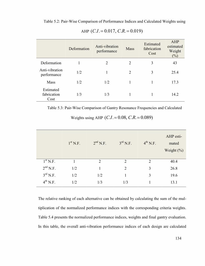
134
Table 5.2: Pair-Wise Comparison of Performance Indices and Calculated Weights using
AHP ( . . 0.017, . . 0.019)C I C R
AHP estimated Weight
(%)
Estimated fabrication
Cost Mass
Anti-vibration performance
Deformation
43 3 2 2 1 Deformation
25.4 3 2 1 1/2 Anti-vibration performance
17.3 1 1 1/2 1/2 Mass
14.2 1 1 1/3 1/3 Estimated fabrication
Cost
Table 5.3: Pair-Wise Comparison of Gantry Resonance Frequencies and Calculated
Weights using AHP ( . . 0.08, . . 0.089)C I C R
AHP esti-
mated
Weight (%)
4th N.F. 3rd N.F. 2nd N.F. 1st N.F.
40.4 2 2 2 1 1st N.F.
26.8 3 2 1 1/2 2nd N.F.
19.6 3 1 1/2 1/2 3rd N.F.
13.1 1 1/3 1/3 1/2 4th N.F.
The relative ranking of each alternative can be obtained by calculating the sum of the mul-
tiplication of the normalized performance indices with the corresponding criteria weights.
Table 5.4 presents the normalized performance indices, weights and final gantry evaluation.
In this table, the overall anti-vibration performance indices of each design are calculated
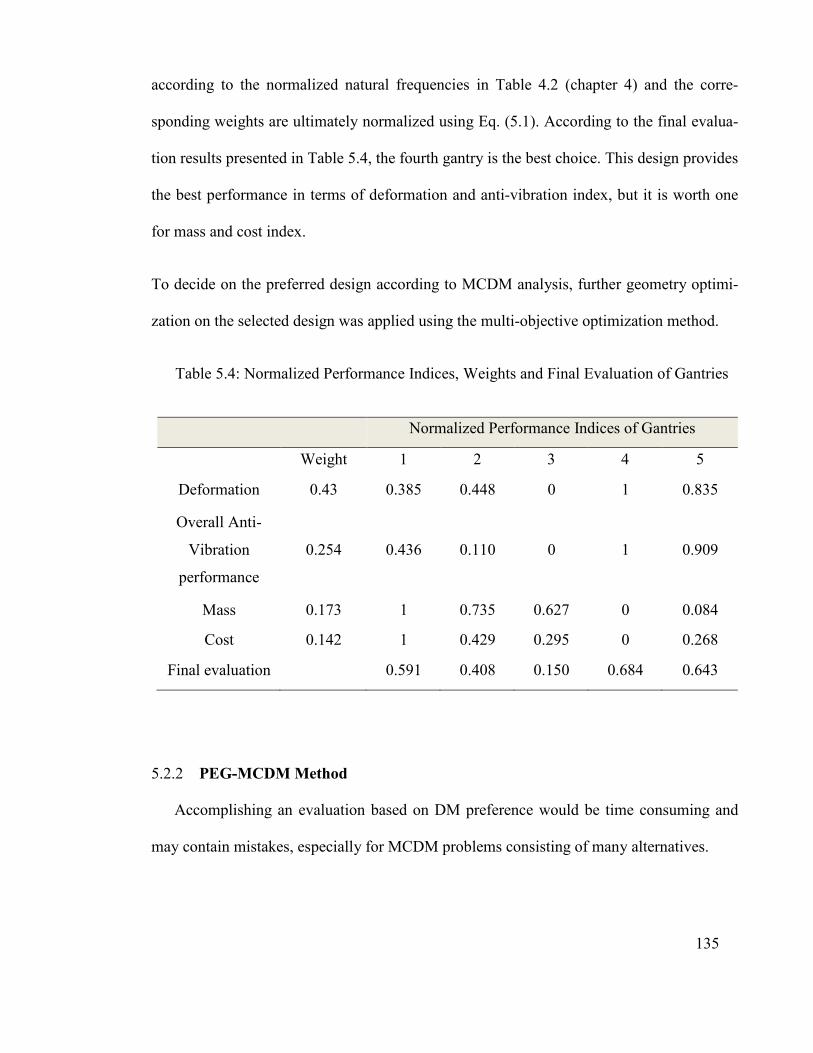
135
according to the normalized natural frequencies in Table 4.2 (chapter 4) and the corre-
sponding weights are ultimately normalized using Eq. (5.1). According to the final evalua-
tion results presented in Table 5.4, the fourth gantry is the best choice. This design provides
the best performance in terms of deformation and anti-vibration index, but it is worth one
for mass and cost index.
To decide on the preferred design according to MCDM analysis, further geometry optimi-
zation on the selected design was applied using the multi-objective optimization method.
Table 5.4: Normalized Performance Indices, Weights and Final Evaluation of Gantries
Normalized Performance Indices of Gantries
Weight 1 2 3 4 5
Deformation 0.43 0.385 0.448 0 1 0.835
Overall Anti-
Vibration
performance
0.254 0.436 0.110 0 1 0.909
Mass 0.173 1 0.735 0.627 0 0.084
Cost 0.142 1 0.429 0.295 0 0.268
Final evaluation 0.591 0.408 0.150 0.684 0.643
5.2.2 PEG-MCDM Method
Accomplishing an evaluation based on DM preference would be time consuming and
may contain mistakes, especially for MCDM problems consisting of many alternatives.

136
The PEG-MCDM method proposed by Grierson (Grierson, 2008) in 2008 is a MCDM
method used to discover the optimum choice among Pareto solutions without requiring DM
preference. The method is based on a trade-off analysis technique adapted from the theory
of social welfare economies (Boadway, 1984).
Originally, Grierson (Grierson, 2008) developed the method for a two-criteria problem
and then advanced it for a general multi-criteria problem. In this thesis, this method is ap-
plied to select among Pareto solutions resulting from multi-objective structural optimiza-
tion of a gantry based on MOGA (Konak, 2006). The procedure of applying PEG-MCDM
is as follows (Grierson, 2008):
5.2.2.1 Initial Normalization
Since the criteria are often non-commensurable and there may large numerical differ-
ences among them, the first step is to map all criteria vectors in the range of [0, 1] where 1
corresponds to the designer's need.
The criteria vector * ( 1, )i
i nf contains the value of each criterion for all alternatives,
where n is the number of criteria. In order to normalize the criteria vector, the following
relation is applicable:
, ,( max( )) / (max( ) min( )); ( 1, ) ( 1, )
i ii j i j iX f i n j m f f f (5.1.a)
, ,( min( )) / (max( ) min( )); ( 1, ) ( 1, )
i ii j i j iX f i n j m f f f (5.1.b)
For the higher-is-better and lower-is-better rules, Eqs. (5.1.a) and (5.1.b) are used, re-
spectively.
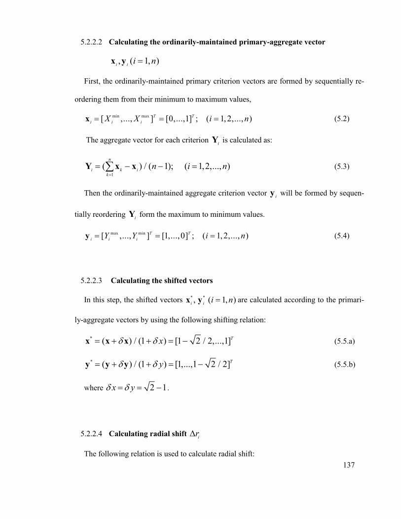
137
5.2.2.2 Calculating the ordinarily-maintained primary-aggregate vector
, ( 1, )i i
i nx y
First, the ordinarily-maintained primary criterion vectors are formed by sequentially re-
ordering them from their minimum to maximum values,
min max[ ,..., ] [0,...,1] ; ( 1,2,..., )T T
i i iX X i n x (5.2)
The aggregate vector for each criterion i
Y is calculated as:
1
( ) / ( 1); ( 1,2,..., )n
ik
k in i n
Y x x (5.3)
Then the ordinarily-maintained aggregate criterion vector i
y will be formed by sequen-
tially reordering i
Y form the maximum to minimum values.
max min[ ,..., ] [1,...,0] ; ( 1,2,..., )T T
i i iY Y i n y (5.4)
5.2.2.3 Calculating the shifted vectors
In this step, the shifted vectors * *, ( 1, )i i
i nx y are calculated according to the primari-
ly-aggregate vectors by using the following shifting relation:
* ) / (1 ) [1 2 / 2,...,1]( Tx xx x (5.5.a)
* ) / (1 ) [1,...,1 2 / 2]( Ty y y y (5.5.b)
where 2 1x y .
5.2.2.4 Calculating radial shift i
r
The following relation is used to calculate radial shift:

138
2 2ii i
r x y (5.6)
where i i
x y is calculated according to the following relation:
* * * * * * * *
1 1 1 10.5 ( )( ) / ( )
j j j j j ji j jix x y y x x yx y y
(5.7)
where j is such that * */ 1j j
x y while * *
1 1/ 1
j jx y
.
5.2.2.5 Evaluating the PEG function
The PEG-function estimates the optimum value of each criterion based on the PEG theo-
ry. The following relation is used to calculate PEG functions:
0 max max min( )( 2 / 2); ( 1, )i i i i i
f irf f f n (5.8)
5.2.2.6 Calculating the mean-square-error (MSE) for each alternative
In obtaining the PEG functions of criteria, the closeness of each alternative to the opti-
mum value is determined by the following relation:
* 201 / (1 / ) ; ( 1, )i i i
MSE n f f i n (5.9)
The alternative with the lowest MSE is set as the best alternative design.
5.3 Multi-objective Structural Optimization of a Gantry
In this section, the fourth gantry design was optimized using MOGA to improve all ob-
jectives excluding cost. Sensitivity analysis was conducted to identify the most effective
parameters among fourteen initial geometrical parameters from Table 5.6 selected intuitive-
ly. After determining the most effective parameters, MOGA was performed using the De-

139
sign Exploration toolbox of ANSYS workbench to obtain the Pareto-optimal solutions. In
order to choose the final configuration, PEG-MCDM was applied.
For gantry optimization ANSYS software was used. First, some gantry dimension pa-
rameters were defined for the optimization process. These parameters were changed during
the process to achieve a new design with new dimensions. Moreover, the results of dynam-
ic and static behavior of the new design were investigated via ANSYS, after which the ob-
jectives were optimized by the special method.
5.3.1 Optimization Objectives
In this process, four objectives were defined for optimization using the ANSYS optimi-
zation package. Initially, four natural frequencies of the gantry related to CNC machine
performance and gantry mass were calculated. Gantry mass must be minimized while the
natural frequencies of the machine must be maximized. Mass is usually opposite the high
natural frequency of the structure, which signifies that the machine’s performance is related
to the natural frequency. The objectives and future conditions (after optimization) are
shown in Table 5.5.
5.3.2 Optimization Method
The ANSYS software offers several optimization methods such as Screening, MOGA,
Adaptive Multiple-Objective methods which are suitable for multi-objective optimization
[Appendix G]. The genetic algorithm is one such method that finds wide applications for
multi-objective optimization problems. Therefore, the method applied was the multi-
objective genetic algorithm (MOGA).
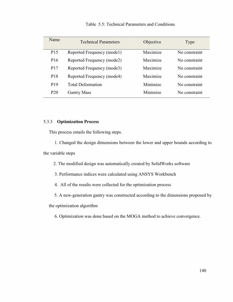
140
Table 5.5: Technical Parameters and Conditions
Name Technical Parameters Objective Type
P15 Reported Frequency (mode1) Maximize No constraint
P16 Reported Frequency (mode2) Maximize No constraint
P17 Reported Frequency (mode3) Maximize No constraint
P18 Reported Frequency (mode4) Maximize No constraint
P19 Total Deformation Minimize No constraint
P20 Gantry Mass Minimize No constraint
5.3.3 Optimization Process
This process entails the following steps.
1. Changed the design dimensions between the lower and upper bounds according to
the variable steps
2. The modified design was automatically created by SolidWorks software
3. Performance indices were calculated using ANSYS Workbench
4. All of the results were collected for the optimization process
5. A new-generation gantry was constructed according to the dimensions proposed by
the optimization algorithm
6. Optimization was done based on the MOGA method to achieve convergence.

141
5.3.4 Structural Multi-Objective Optimization of a Gantry using MOGA (Multi-
Objective Optimization Algorithm)
Upon selecting the preferred configuration, the structural optimization of the gantry is a
valuable task for further improving the performance indices. Each performance index indi-
cates an objective that the optimization algorithm attempts to improve. Since in gantry op-
timization more than one objective takes part in overall performance, a multi-objective op-
timization algorithm must be employed.
Unlike a single-objective optimization problem that contains a single, global optimum solu-
tion, multi-objective optimization problems contain many optimum solutions. The defini-
tion of an optimal solution is not straightforward, as it defines a single-objective optimiza-
tion problem. Pareto-optimal solutions or non-dominant solutions are multi-objective opti-
mization problem solutions. A Pareto-optimal solution is achieved when it is not possible to
further improve a single selected objective without causing at least one other objective to
deteriorate (Deb, 2001).
Design Exploration of the ANSYS workbench provides many important and practical
means for design optimization, including several algorithms for multi-objective optimiza-
tion. Among the numerous multi-objective optimizations, MOGA has been exploited in
many engineering design problems (Andersson, 2003). In this thesis, MOGA is employed
to explore the design space and identify Pareto-optimal solutions. Due to the gantry’s con-
figuration complexity, initial parameter selection was carried out intuitively. Figure 5.1
shows the initial design parameters.
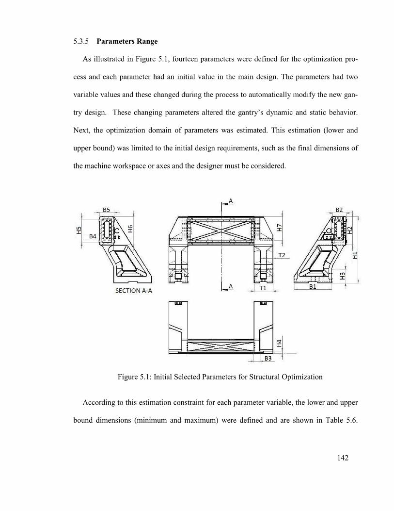
142
5.3.5 Parameters Range
As illustrated in Figure 5.1, fourteen parameters were defined for the optimization pro-
cess and each parameter had an initial value in the main design. The parameters had two
variable values and these changed during the process to automatically modify the new gan-
try design. These changing parameters altered the gantry’s dynamic and static behavior.
Next, the optimization domain of parameters was estimated. This estimation (lower and
upper bound) was limited to the initial design requirements, such as the final dimensions of
the machine workspace or axes and the designer must be considered.
Figure 5.1: Initial Selected Parameters for Structural Optimization
According to this estimation constraint for each parameter variable, the lower and upper
bound dimensions (minimum and maximum) were defined and are shown in Table 5.6.

143
The parameter ranges for sensitivity analysis and optimization are as follows (all units are
in millimeters):
The Pareto analysis is a formal technique where many possible courses of action are
competing for attention. In fact, the problem solver estimates the value delivered by each
action, then selects a number of the most effective actions that deliver a total value reason-
ably close to the maximal possible one. Table 5.7 shows the organization of the ANSYS
optimization process carried out in this work.
Table 5.6: The Lower and Upper Bounds of Parameters (Gantry Dimensions)
No. Optimization Domain Base Dimension Lower Bound Upper Bound
1 T1 200 180 220
2 B4 100 90 110
3 H5 250 240 260
4 H6 300 285 315
5 B5 150 140 160
6 T2 70 60 80
7 H7 250 225 270
8 B3 60 54 66
9 H4 25 22.5 27.5
10 B1 400 380 420
11 H1 700 675 725
12 B2 150 140 160
13 H2 300 280 320
14 H3 170 160 180
5.3.6 Sensitivity Analysis of the Parameters and Optimization
Sensitivity analysis reveals the significance of each parameter. Figure 5.2 presents the
sensitivity analysis results obtained using the Design Exploration toolbox of ANSYS.
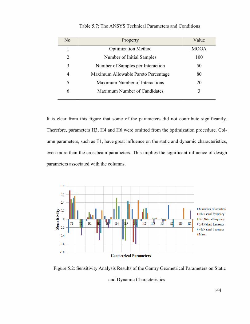
144
Table 5.7: The ANSYS Technical Parameters and Conditions
No. Property Value
1 Optimization Method MOGA
2 Number of Initial Samples 100
3 Number of Samples per Interaction 50
4 Maximum Allowable Pareto Percentage 80
5 Maximum Number of Interactions 20
6 Maximum Number of Candidates 3
It is clear from this figure that some of the parameters did not contribute significantly.
Therefore, parameters H3, H4 and H6 were omitted from the optimization procedure. Col-
umn parameters, such as T1, have great influence on the static and dynamic characteristics,
even more than the crossbeam parameters. This implies the significant influence of design
parameters associated with the columns.
Figure 5.2: Sensitivity Analysis Results of the Gantry Geometrical Parameters on Static
and Dynamic Characteristics

145
MOGA was performed using the design exploration toolbox of ANSYS workbench. As
convergence criteria, the maximum allowable Pareto percentage was set to 80%. The popu-
lations of the first and later generations were 100 and 50 (Sensitivity Analysis of the Pa-
rameters and Optimization
Sensitivity analysis reveals the significance of each parameter. Figure 5.2 presents the sen-
sitivity analysis results obtained using the Design Exploration toolbox of ANSYS.
Table 5.7 MOGA converged automatically after 243 evaluations. The five candidate points
selected among the Pareto-optimum solutions are shown in Table 5.8. These are non-
dominated solutions. In order to select the final optimal solution, PEG-MCDM was em-
ployed as described in section 5.2. Following the previously outlined procedure, the nor-
malization of criteria values, primary-aggregate vectors, radial shifts and PEG-functions
were evaluated for each criterion as shown in Table 5.9. Accordingly, the MSE (Mean-
Square-Error) value of each candidate point was calculated using Eq. (5.9). Table 5.10 re-
veals the MSE values of the design alternatives.
According to the results, the fifth solution offers the least MSE and is the best option intro-
duced by the PEG-MCDM method. Therefore, this option was considered the final choice.
Upon finalizing the multi-criteria design stage, the prototype was fabricated according to
the geometrical parameters of the fifth design. This prototype was used to investigate and
ensure the accuracy of the FE model.

146
Table 5.8: Candidates Revealed by MOGA
Candidates 1 2 3 4 5
1T 215.4 215.4 212.2 212.2 209.64
2T 61.75 61.75 66.25 66.25 65.57
1B 399.51 418.99 385.71 385.71 394.18
2B 148.85 148.85 142.6 142.6 142.75
3B 54.54 55.022 60.917 60.917 63.15
4B 102.27 102.27 93.57 93.53 100.72
5B 156.57 156.81 144.80 144.80 141.58
1H 682.25 689.27 677.25 677.28 681.74
2H 312.79 311.85 297.97 297.97 313.78
5H 254.83 254.83 244.31 244.41 251.84
7H 237.86 237.86 241.58 239.69 229.64
Max Deformation
(mm) 0.0032 0.0033 0.0033 0.0033 0.0035
1st natural
frequency (Hz) 315.13 314.59 313.09 313.10 315.97
2nd natural
frequency (Hz) 321.55 318.57 318.63 318.37 322.48
3rd natural
frequency (Hz) 507.05 504.18 503.93 503.57 497.94
4th natural
frequency (Hz) 655.98 656.19 640.02 640.34 640.55
Mass (kg) 544.95 556.24 517.99 519.13 513.88

147
Table 5.9: Maximum, Minimum, Radial shift i
r and PEG-functions of Design Criteria
min
if max
if
ir 0
if
Max defor-
mation
0.0032
0.0035
-0.27008
0.003442
1st Natural
freq. (Hz)
385.7172
418.998
-0.08545
398.5451
2nd Natural
freq. (Hz)
313.0993
315.9777
-0.20628
314.5566
3rd Natural
freq. (Hz)
318.3707
322.4886
-0.13778
320.1734
4th Natural
freq. (Hz)
497.9459
507.0545
-0.33448
503.7251
Mass (kg) 640.0225
656.1948
-0.22875
648.5735
Table 5.10: MSE Values of Design Alternatives Introduced by MOGA
Candidates 1 2 3 4 5
MSE 0.000436 0.000635 0.000464 0.000478 0.000308
5.3.7 The Final Design Obtained with Optimization
Based on the modification process, the final modified gantry machine design is shown in
Figure 5.3 and three views of the “FINAL” new type of CNC gantry machine are shown in
Figure 5.4. Defining the technology for fabricating the components with available facilities,
ease of fabrication and low cost fabrication are the targets of the next stage. The design

148
team has prepared documents, such as 3D and detailed drawing files for fabrication. All
CNC design documentation is attached in the index.
(a) Optimized CNC Gantry Machine without Cover
(b) The New CNC Gantry Machine with Cover
Figure 5.3: The Optimized Design of the New CNC Gantry Machine

Figure 5.4: Three Views of the “FINAL” New CNC Gantry Machine
5.4 Conclusion
Improving static and dynamic char
This implies that in the design stage, many conflicting criteria must be taken into consi
eration to meet the machine performance indices as well as fulfill market demand. Combi
ing experts’ knowledge
as a guide in the design stage, which further yielded confidence regarding the final design
configuration.
The performance indices used were the maximum static deformation of the gantry, the
first four natural frequencies, mass and fabrication cost. According to the designers’ jud
: Three Views of the “FINAL” New CNC Gantry Machine
Improving static and dynamic characteristics may ultimately cause higher mass and cost.
This implies that in the design stage, many conflicting criteria must be taken into consi
tion to meet the machine performance indices as well as fulfill market demand. Combi
ing experts’ knowledge and experience along with well-developed MCDM methods served
as a guide in the design stage, which further yielded confidence regarding the final design
The performance indices used were the maximum static deformation of the gantry, the
st four natural frequencies, mass and fabrication cost. According to the designers’ jud149
: Three Views of the “FINAL” New CNC Gantry Machine
acteristics may ultimately cause higher mass and cost.
This implies that in the design stage, many conflicting criteria must be taken into consid-
tion to meet the machine performance indices as well as fulfill market demand. Combin-
developed MCDM methods served
as a guide in the design stage, which further yielded confidence regarding the final design
The performance indices used were the maximum static deformation of the gantry, the
st four natural frequencies, mass and fabrication cost. According to the designers’ judg-

150
ment, the significance of the criteria was determined using the AHP method. After normal-
izing the performance indices, the optimal configuration was selected based on merit as
calculated by aggregating the weighted normalized performance indices.
MOGA was employed to additionally improve the performance indices. Prior to optimiza-
tion, sensitivity analysis was done to eliminate insignificant parameters. The sensitivity
analysis results signified a major contribution of the columns on the static and dynamic
characteristics of the gantry relative to the crossbeam's contribution. Five design points
were chosen through Pareto-optimal solutions revealed by MOGA. These non-dominated
design points were examined by PEG-MCDM technique to identify the ultimate configura-
tion. The manufacturing process of the new type of CNC gantry machine designed and dis-
cussed in the last chapters will be presented in the subsequent chapter.
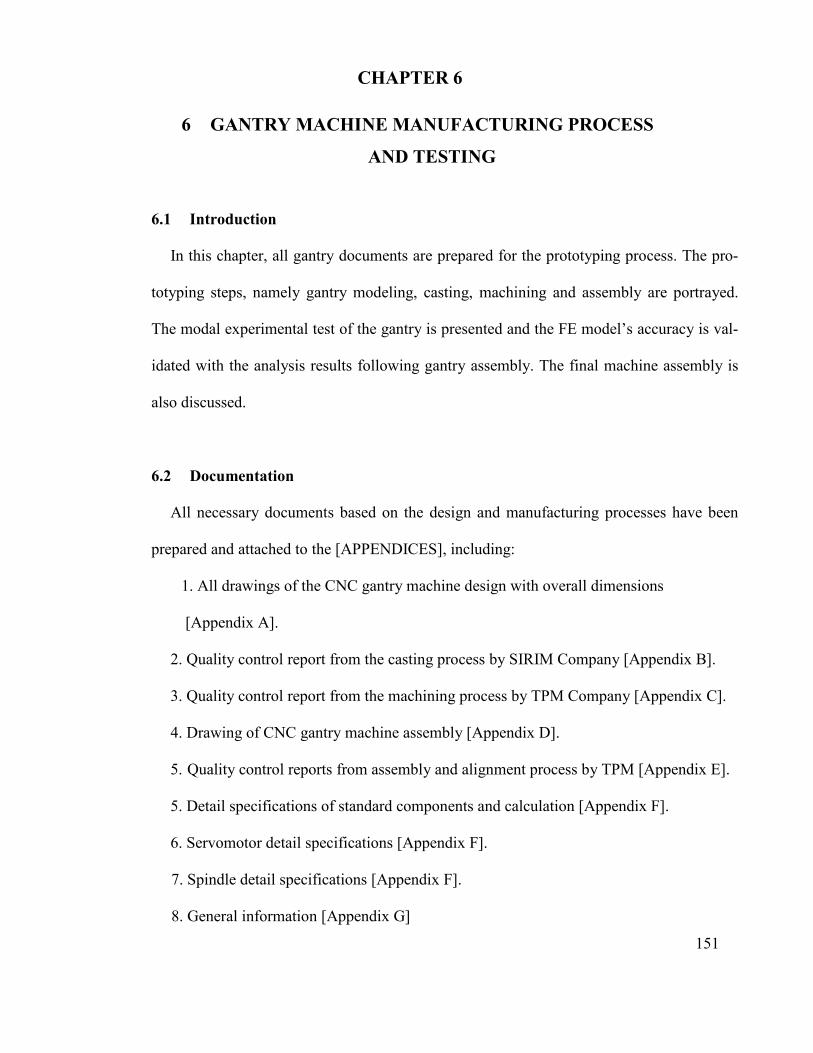
151
6.1 Introduction
In this chapter, all gantry documents are prepared for the prototyping process. The pro-
totyping steps, namely gantry modeling, casting, machining and assembly are portrayed.
The modal experimental test of the gantry is presented and the FE model’s accuracy is val-
idated with the analysis results following gantry assembly. The final machine assembly is
also discussed.
6.2 Documentation
All necessary documents based on the design and manufacturing processes have been
prepared and attached to the [APPENDICES], including:
1. All drawings of the CNC gantry machine design with overall dimensions
[Appendix A].
2. Quality control report from the casting process by SIRIM Company [Appendix B].
3. Quality control report from the machining process by TPM Company [Appendix C].
4. Drawing of CNC gantry machine assembly [Appendix D].
5. Quality control reports from assembly and alignment process by TPM [Appendix E].
5. Detail specifications of standard components and calculation [Appendix F].
6. Servomotor detail specifications [Appendix F].
7. Spindle detail specifications [Appendix F].
8. General information [Appendix G]
CHAPTER 6
6 GANTRY MACHINE MANUFACTURING PROCESS
AND TESTING
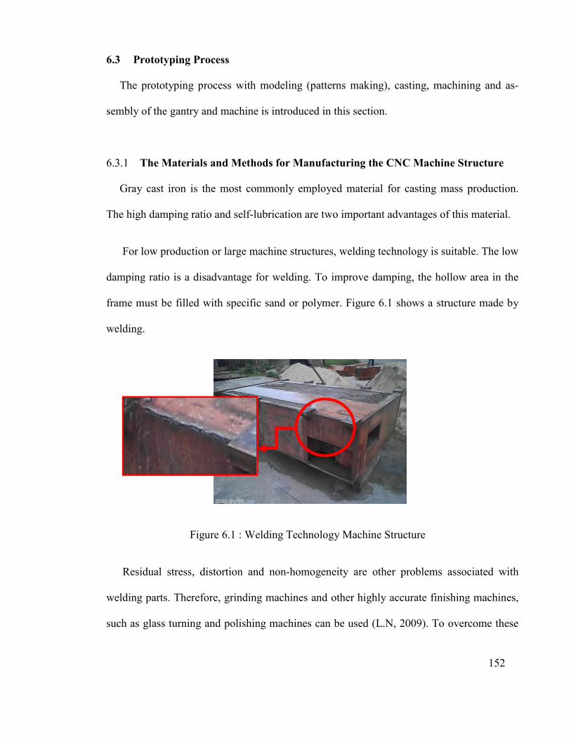
152
6.3 Prototyping Process
The prototyping process with modeling (patterns making), casting, machining and as-
sembly of the gantry and machine is introduced in this section.
6.3.1 The Materials and Methods for Manufacturing the CNC Machine Structure
Gray cast iron is the most commonly employed material for casting mass production.
The high damping ratio and self-lubrication are two important advantages of this material.
For low production or large machine structures, welding technology is suitable. The low
damping ratio is a disadvantage for welding. To improve damping, the hollow area in the
frame must be filled with specific sand or polymer. Figure 6.1 shows a structure made by
welding.
Figure 6.1 : Welding Technology Machine Structure
Residual stress, distortion and non-homogeneity are other problems associated with
welding parts. Therefore, grinding machines and other highly accurate finishing machines,
such as glass turning and polishing machines can be used (L.N, 2009). To overcome these

153
issues, casting technology is more suitable for machine prototyping. The casting process is
introduced in the next section.
6.3.2 Casting Process
In this step, the design of the main machine components, i.e. structure, columns, cross-
beam, worktable, Y and Z-axis carriages, spindle holder and column base is prepared for
pattern-making. The patterns are made by special CNC machine based on a calculation of
the shrinkage requirement. The patterns are made of expanded Polystyrene (EPS) material,
which is suitable for easy and fast casting. EPS is also cheaper than other materials, but it
can only be used once. The crossbeam pattern is shown in Figure 6.2.
Figure 6.2 : The Crossbeam Pattern
154
The component patterns are placed in a mold for casting. Some special sand is strewed
in the mold. The molding process of a CNC machine structure is shown in Figure 6.3.
(a) Sand Mold of the Machine Structure
The Molding Process
Figure 6.3: The Molding Process of the Machine Structure

155
For casting, gray cast iron material is suggested for gantry prototyping. The specifica-
tions of this material are given in Table 6.1.
Table 6.1: Specifications of Casting Material
All components were produced by casting method with EPS patterns. The molding pro-
cess was very difficult and took time because the patterns were not rigid enough. The dif-
ferent casted components are illustrated in Figure 6.4.
6.3.3 Machining Process
For machining the components, the methods and manufacturing technologies must be
prepared as detailed drawings. Quality control and assembly instruction are two important
steps. To prepare these requirements and prototype the CNC machine, one of the best gov-
ernmental companies in Malaysia, TPM (Technology Park Malaysia) with good experience
in producing CNC milling machines, was chosen. TPM prepared the technical instructions
for machining, quality control and assembly based on the CNC machine documents submit-
ted to them. Thus, all components were fabricated by CNC machine at TPM.

156
(a) Columns, Spindle carriage, Spindle clamp and Base columns
(b) Crossbeam, Spindle holder, Worktable
(c) Machine bed
Figure 6.4: Casted CNC Machine Components

157
The CNC vertical machine was used for some components and the CNC horizontal ma-
chine for others. The machine components fabricated at TPM are shown in Figure 6.5.
(a) Spindle carriage, Base columns and Spindle holder
(a) Machine Worktable
(a) Machine Structure
(d) The Column
Figure 6.5 : CNC Machine Components in the Machining Process
6.4 Modal Testing and Analysis of the Manufactured Gantry
Before final machine assembly, the CNC machine gantry was assembled for modal test-
ing and analysis. A gantry vibration test was required to verify the gantry’s dynamic behav-
ior as investigated via modal analysis in ANSYS software. The assembled gantry is shown
in Figure 6.6.
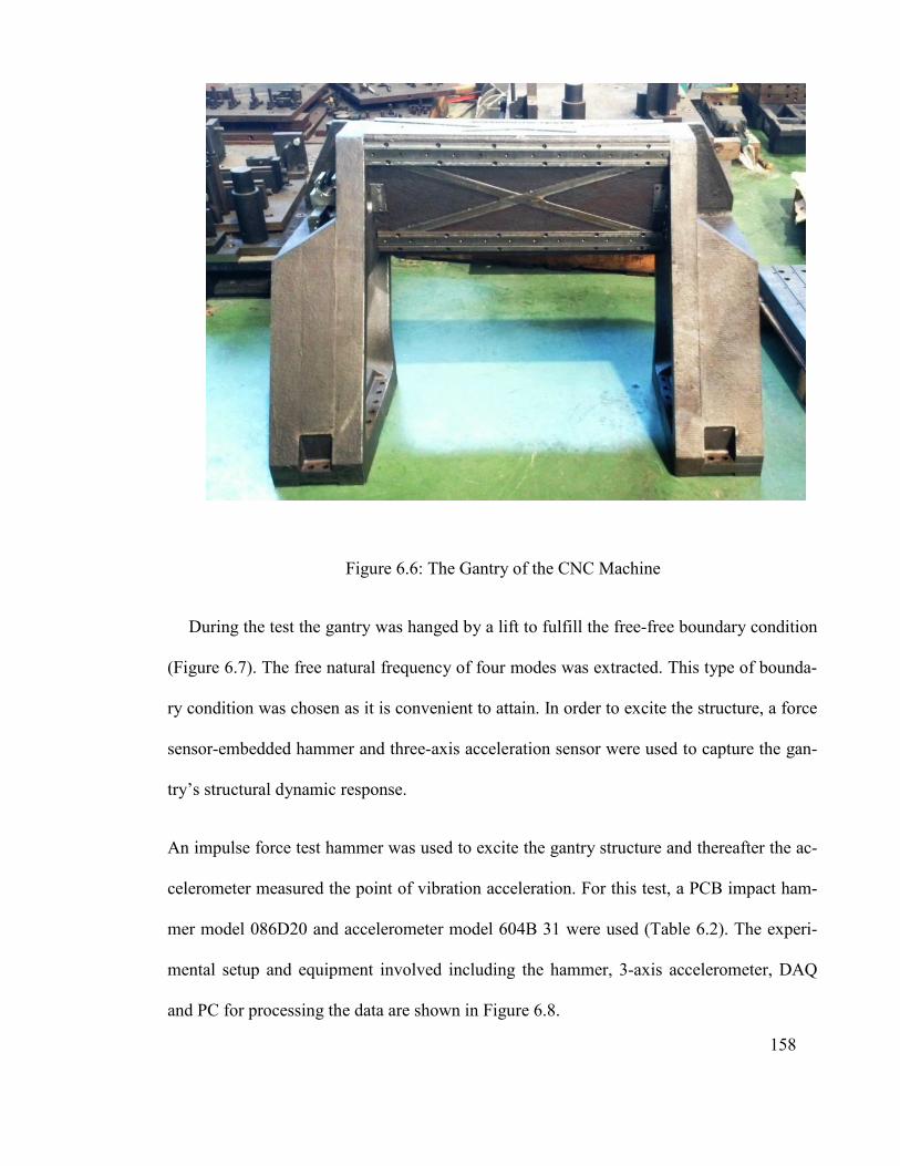
158
Figure 6.6: The Gantry of the CNC Machine
During the test the gantry was hanged by a lift to fulfill the free-free boundary condition
(Figure 6.7). The free natural frequency of four modes was extracted. This type of bounda-
ry condition was chosen as it is convenient to attain. In order to excite the structure, a force
sensor-embedded hammer and three-axis acceleration sensor were used to capture the gan-
try’s structural dynamic response.
An impulse force test hammer was used to excite the gantry structure and thereafter the ac-
celerometer measured the point of vibration acceleration. For this test, a PCB impact ham-
mer model 086D20 and accelerometer model 604B 31 were used (Table 6.2). The experi-
mental setup and equipment involved including the hammer, 3-axis accelerometer, DAQ
and PC for processing the data are shown in Figure 6.8.
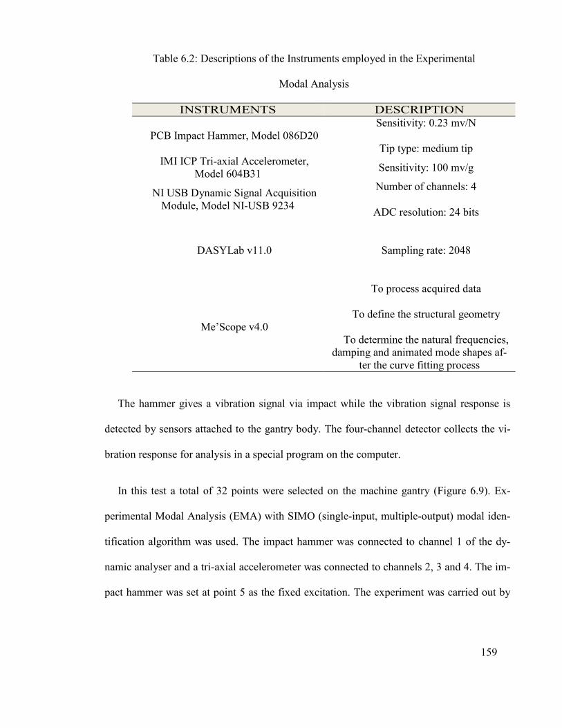
159
Table 6.2: Descriptions of the Instruments employed in the Experimental
Modal Analysis
DESCRIPTION INSTRUMENTS Sensitivity: 0.23 mv/N
Tip type: medium tip PCB Impact Hammer, Model 086D20
Sensitivity: 100 mv/g IMI ICP Tri-axial Accelerometer,
Model 604B31 Number of channels: 4
ADC resolution: 24 bits
NI USB Dynamic Signal Acquisition Module, Model NI-USB 9234
Sampling rate: 2048
DASYLab v11.0
To process acquired data
To define the structural geometry
To determine the natural frequencies, damping and animated mode shapes af-
ter the curve fitting process
Me’Scope v4.0
The hammer gives a vibration signal via impact while the vibration signal response is
detected by sensors attached to the gantry body. The four-channel detector collects the vi-
bration response for analysis in a special program on the computer.
In this test a total of 32 points were selected on the machine gantry (Figure 6.9). Ex-
perimental Modal Analysis (EMA) with SIMO (single-input, multiple-output) modal iden-
tification algorithm was used. The impact hammer was connected to channel 1 of the dy-
namic analyser and a tri-axial accelerometer was connected to channels 2, 3 and 4. The im-
pact hammer was set at point 5 as the fixed excitation. The experiment was carried out by
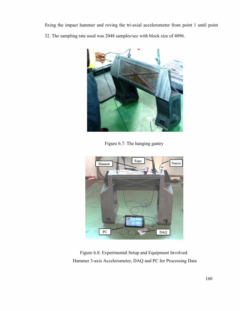
160
fixing the impact hammer and roving the tri-axial accelerometer from point 1 until point
32. The sampling rate used was 2048 samples/sec with block size of 4096.
Figure 6.7: The hanging gantry
Figure 6.8: Experimental Setup and Equipment Involved:
Hammer 3-axis Accelerometer, DAQ and PC for Processing Data

161
Structural Wire-mesh Model of machine
tool gantry columns
Measurement Points and Locations of
crossbeam on the machine tool gantry
Figure 6.9: Excitation Points and Sensor Locations
The free natural frequency of the gantry’s four modes of vibration was extracted via
modal analysis in ANSYS software before the testing process. The experimental results
were compared with the FE. The gantry’s natural frequency results from modal analysis are
shown in Table 6.3.
The results show that the mode shape of frequency response in both analyses (FE and
EME) was the same. The FE results for the gantry compared with experimental modal
analysis (EMA) are given in Table 6.3. It can be seen the results are close to each other,
meaning that the modification process of the gantry design was acceptable.

162
Table 6.3: The Results of Finite Element and Experimental Modal Analysis of the Gantry
Mode shapes FE (Finite Element)
Modal Analysis
EMA (Experimental Modal
Analysis)
Frequency of Mode1 117.50Hz 101Hz
Frequency of Mode2 179.55Hz 175Hz
Frequency of Mode3 238.38Hz 210Hz
Frequency of Mode4 333.38Hz 300Hz
Experimental and FE-predicted mode shapes and associated natural frequencies are
compared in Table 6.4. According to these results, the FE model adequately represents the
actual experimental structural behavior, meaning the model can be used to predict the struc-
ture’s behavior.
6.5 Assembly of the CNC Gantry Machine
The CNC gantry machine was assembled in four steps as follows:
1. Investigated suitable standard components for the machine
2. Assembled the structure including the worktable and base columns
3. Assembled the gantry to the machine bed
4. Assembled the spindle carriage holder to the gantry

163
Table 6.4: Experimental and FE Mode Shapes and Corresponding Natural Frequencies
Mode No.
FE Predicted Mode Shapes Experimental Mode Shapes Er-
ror%
1
117.5 Hz
101Hz
16.33
2
179.55 Hz
175 Hz
2.6
3
238.46 Hz
210 Hz
13.55
4
333.38 Hz
300 Hz
11.12

164
6.5.1 Standard Components of the CNC Machine
6.5.1.1 Selection of Guideways
The guideways are directly responsible for the precision and smoothness of the ma-
chine’s axis movements. The required functional parameters for the longitudinal guideways
are:
- Geometric perfection -- any guideway defect will be transferred into the moving part
and create non-accuracy.
- Stiffness -- the guide must withstand the cutting forces and inertial loads without de-
formations.
- Wear resistance -- good frictional feature is valued for guideway surface or rolling el-
ements.
- Sufficient toughness -- to withstand small impacts from the machining process, espe-
cially in case of highly interrupted cutting. Figure 2.21Based on the requirements, standard
linear guides were chosen for the CNC gantry machine. Two types of linear guide were se-
lected for this machine, namely “RGW25CC” and “RGW30CC” of the rolling circulation
system type from HIWIN Company. This type of linear guide is suitable for heavy loads, as
rollers are used instead of balls for circulation in the linear block.
Figure 6.10 shows the rolling type of linear guides and Figure 6.11 presents the RGW-
CC/ RGW-HC series of linear guides. According to the information of standard CNC ma-
chine components from a linear guide catalogue, suitable linear guides were selected for the
machine. The RGW25 CC was selected for the U-axis (the gantry) and Y- and Z-axis feed
drive motions and RGW30 was chosen for the X-axis feed drive motion of the CNC gantry
machine (Figure 6.12).

165
Figure 6.10: Rolling Circulation System in the RG Type of Linear guide (Hiwin
technologies corp, 2011)
Figure 6.11: The RGW-CC/ RGW-HC Series of Linear Guide (Hiwin technologies corp,
2011)
The detailed specifications of the linear guides are provided in Table 6.5 and the tech-
nical information for these linear guides of two sizes, such as dimensions, basic dynamic
load rating, basic static rating, static rated moment and calculation of applied loads are
shown in [Appendix F]

166
Figure 6.12: Installation of the Linear guides
Table 6.5: The Linear Guides Selected for the CNC Gantry Machine
AXES Model WR HR W L
1 X-axis RGW30CC 28 28 90 109.8
2 U-axis RGW25CC 23 23.6 70 97.9
3 Y-axis RGW25CC 23 23.6 70 97.9
4 Z-axis RGW25CC 23 23.6 70 97.9
RGW25 CC
RGW25 CC RGW25 CC
RGW25 CC
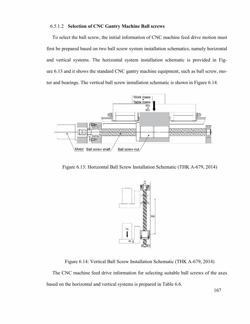
167
6.5.1.2 Selection of CNC Gantry Machine Ball screws
To select the ball screw, the initial information of CNC machine feed drive motion must
first be prepared based on two ball screw system installation schematics, namely horizontal
and vertical systems. The horizontal system installation schematic is provided in Fig-
ure 6.13 and it shows the standard CNC gantry machine equipment, such as ball screw, mo-
tor and bearings. The vertical ball screw installation schematic is shown in Figure 6.14.
Figure 6.13: Horizontal Ball Screw Installation Schematic (THK A-679, 2014)
Figure 6.14: Vertical Ball Screw Installation Schematic (THK A-679, 2014)
The CNC machine feed drive information for selecting suitable ball screws of the axes
based on the horizontal and vertical systems is prepared in Table 6.6.
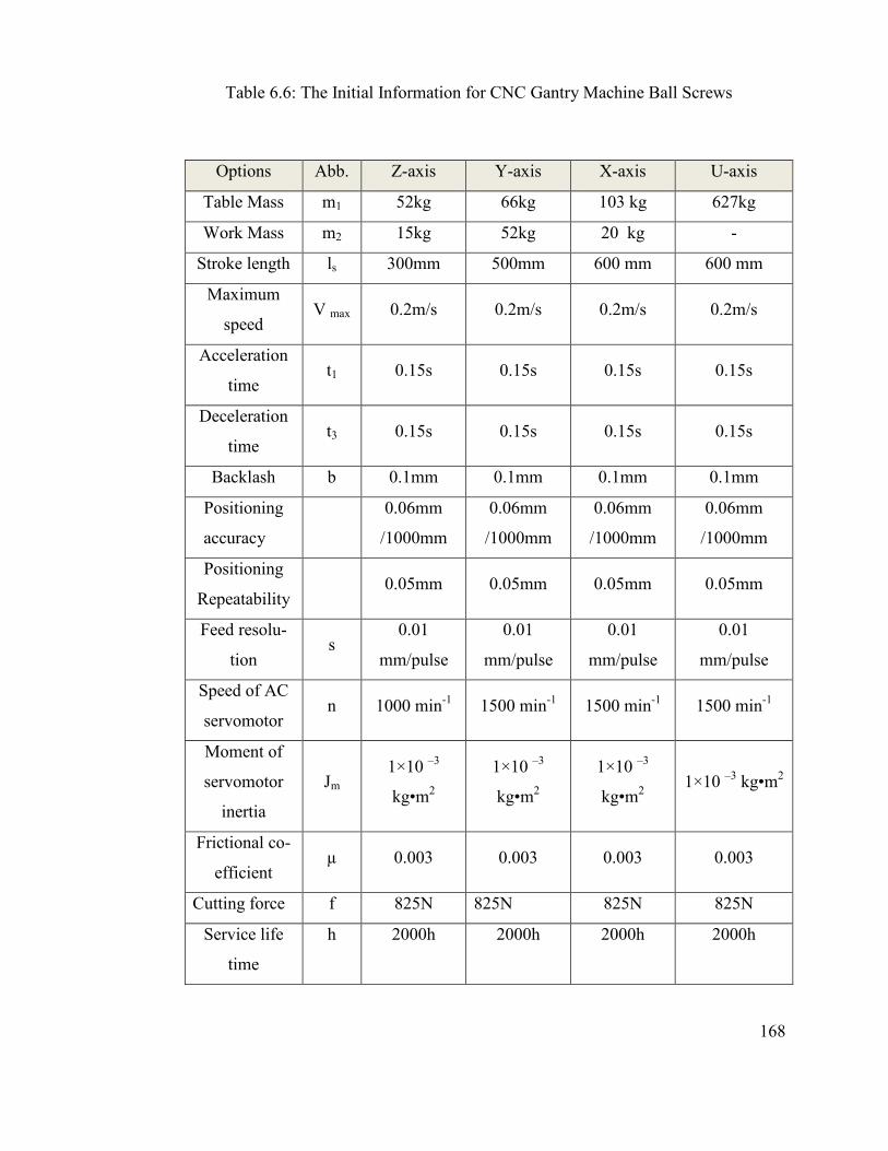
168
Table 6.6: The Initial Information for CNC Gantry Machine Ball Screws
Options Abb. Z-axis Y-axis X-axis U-axis
Table Mass m1 52kg 66kg 103 kg 627kg
Work Mass m2 15kg 52kg 20 kg -
Stroke length ls 300mm 500mm 600 mm 600 mm
Maximum
speed V max 0.2m/s 0.2m/s 0.2m/s 0.2m/s
Acceleration
time t1 0.15s 0.15s 0.15s 0.15s
Deceleration
time t3 0.15s 0.15s 0.15s 0.15s
Backlash b 0.1mm 0.1mm 0.1mm 0.1mm
Positioning
accuracy
0.06mm
/1000mm
0.06mm
/1000mm
0.06mm
/1000mm
0.06mm
/1000mm
Positioning
Repeatability 0.05mm 0.05mm 0.05mm 0.05mm
Feed resolu-
tion s
0.01
mm/pulse
0.01
mm/pulse
0.01
mm/pulse
0.01
mm/pulse
Speed of AC
servomotor n 1000 min-1 1500 min-1 1500 min-1 1500 min-1
Moment of
servomotor
inertia
Jm 1×10 –3
kg•m2
1×10 –3
kg•m2
1×10 –3
kg•m2 1×10 –3 kg•m2
Frictional co-
efficient µ 0.003 0.003 0.003 0.003
Cutting force f 825N 825N 825N 825N
Service life
time
h 2000h 2000h 2000h 2000h
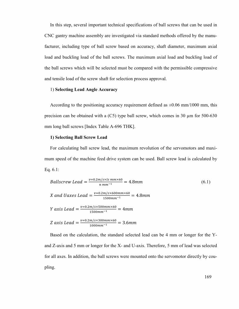
169
In this step, several important technical specifications of ball screws that can be used in
CNC gantry machine assembly are investigated via standard methods offered by the manu-
facturer, including type of ball screw based on accuracy, shaft diameter, maximum axial
load and buckling load of the ball screws. The maximum axial load and buckling load of
the ball screws which will be selected must be compared with the permissible compressive
and tensile load of the screw shaft for selection process approval.
1) Selecting Lead Angle Accuracy
According to the positioning accuracy requirement defined as ±0.06 mm/1000 mm, this
precision can be obtained with a (C5) type ball screw, which comes in 30 µm for 500-630
mm long ball screws [Index Table A-696 THK].
1) Selecting Ball Screw Lead
For calculating ball screw lead, the maximum revolution of the servomotors and maxi-
mum speed of the machine feed drive system can be used. Ball screw lead is calculated by
Eq. 6.1:
������������� =���.��/�������
����� = 4.8�� (6.1)
������������� =���.��/��������
�������� = 4.8��
��������� =���.��/��������
�������� = 4��
��������� =���.��/��������
��������= 3.6��
Based on the calculation, the standard selected lead can be 4 mm or longer for the Y-
and Z-axis and 5 mm or longer for the X- and U-axis. Therefore, 5 mm of lead was selected
for all axes. In addition, the ball screws were mounted onto the servomotor directly by cou-
pling.

170
3) Selecting a Screw Shaft Diameter
In the standard catalog for ball screws with 5 mm of lead, several different diameters
(14, 16, 20, 25 mm) [Index A-711THK] for shaft are offered by manufacturers. According
to the design limitations, 20 mm diameter was selected for the CNC gantry machine axes,
but the selected diameter must be supported by calculation. The maximum axial and buck-
ling loads of the selected ball screw are calculated in the next step. Both loads must be less
than the permissible load.
5) Calculating the Maximum Axial Load of the X-axis Ball screw
The calculation process will only be done for the X and U axes, but the results can be
used for all axes because the condition of these two ball screws is more critical than the Y
and Z axes.
Considering Table 6.6 where the cutting force (section 4.4.2) is f=825N, mass is m1
=130 kg, work mass is m2 = 20 kg, frictional coefficient of the guide surface is μ= 0.003,
maximum speed is Vmax=0.2 m/s, gravitational acceleration is g = 9.807 m/s2 and accelera-
tion time is t1 = 0.15s; then the maximum acceleration and maximum axial load are ob-
tained by Eq. 6.2-6.8 respectively:
� =����
�� (6.2)
� =�.�
�.��= 1.33�/��
The maximum axial load during forward acceleration will be obtained by Eq. 6.3:
Fa1 = μ× (m1 + m2) g + f + (m1 + m2) ×α (6.3)
Fa1 (X axis) = 0.003× (130+20)×9.807+825+ (130+20)×1.33=1028.9N
Fa1 (U axis) = 0.003× (627/2)×9.807+825+ (627/2)×1.33=1251.1N

171
The maximum axial load during forward uniform motion will be obtained by Eq. 6.4:
Fa2 = μ× (m1 + m2) g + f (6.4)
Fa2 (X axis) = 0.003× (130+20)×9.807+825 = 829.4N
Fa2 (U axis) = 0.003× (627/2)×9.807+825 = 834.2N
The maximum axial load during forward deceleration will be obtained by Eq. 6.5:
Fa3 = μ× (m1 + m2) ×g + f – (m1 + m2) ×α (6.5)
Fa3 (X axis) = 0.003× (130+20)×9.807+825– (130+20)×1.33= 629.9N
Fa3 (U axis) 0.003× (627/2)×9.807+825– (627/2)×1.33= 417.2N
The maximum axial load during backward acceleration will be obtained by Eq. 6.6:
Fa4 = – μ× (m1 + m2) ×g – f – (m1 + m2) × α (6.6)
Fa4 (X axis) = – 0.003× (130+20)×9.807–825– (130+20)×1.33= –1028.9 N
Fa4 (U axis) = – 0.003× (627/2)×9.807–825– (627/2)×1.33= –1251.1 N
The maximum axial load during uniform backward motion will be obtained by Eq. 6.7:
Fa5 = – μ× (m1 + m2) ×g – f (6.7)
Fa5 (X axis) = – 0.003×(130+20)×9.807– 825= –829.4 N
Fa5 (U axis) = – 0.003×(627/2)×9.807– 825= –834.2 N
The maximum axial load during backward deceleration will be obtained by Eq. 6.8:
Fa6 = – μ× (m1 + m2) ×g – f + (m1 + m2) ×α (6.8)
Fa6 (X axis) = – 0.003× (130+20)×9.807– 825+ (130+20)×1.33= – 629.91 N
Fa6 (U axis) = – 0.003× (627/2)×9.807– 825+ (627/2)×1.33= – 417.2 N

172
Thus, the maximum axial load applied on the ball screw is Fa max for Fa1(X axis) = 1028.9
N and Fa1 (U axis) =1251.1N.
6) Buckling Load on the Screw Shaft
According to the minor thread diameter of the ball screw (17.5 mm), the distance be-
tween two bearings La X axis = 820mm, La U axis = 757 mounted on the ball screw and the
mounting method factor (η2=10) related to the fixed-supported condition [Index A-712
THK], the buckling load (P1) will be obtained by Eq.6.9:
�� = �� ���
��� × 10� (6.9)
������� = 2 ��.��
����× 10�= 2789.6N
������� = 2 ��.��
����× 10�= 3273.3N
7) Permissible Compressive and Tensile Load of the Screw Shaft
According to the minor thread diameter of the ball screw shaft (d1 =17.5 mm), the per-
missible compressive and tensile load of the ball screw can be obtained from Eq. 6.11.
P2 = 116 × d12 (6.11)
P2=116 × (17.5)2 =35525 N
However, the calculation result shows that the maximum axial load (Fa1(X axis) =
1028.9N, Fa1 (U axis) = 1251.1N) is less than buckling load (P1(X axis) =2789.6N, P1 (U axis) =
3273.3N). Also, this load is less than the permissible compressive and tensile load
(P2=35525N), hence these ball screws can work with no problem.

6.5.1.3 Slelection of Ball Screw End Support
The end supports are standard bearings that can facilitate easy ball screw installation
The two types of end support are fixed and free end support.
support and Figure 6.16
Figure 6
Slelection of Ball Screw End Support
The end supports are standard bearings that can facilitate easy ball screw installation
The two types of end support are fixed and free end support. Figure 6.15
shows a free end support.
6.15: Fixed End Support (BK type) (Hiwin Company
173
The end supports are standard bearings that can facilitate easy ball screw installation.
Figure 6.15 shows a fixed end
Hiwin Company)
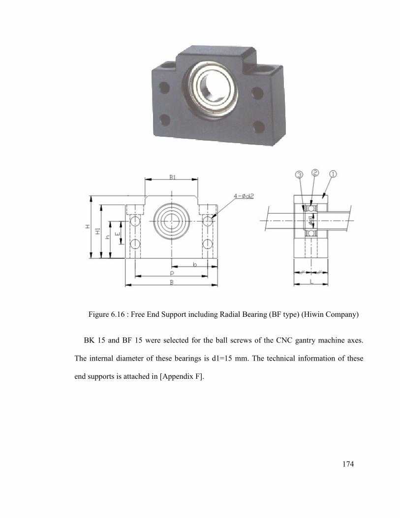
Figure 6.16 : Free End Support including Radial Bearing (BF type)
BK 15 and BF 15 were selected for the ball screws of the CNC gantry machine axes.
The internal diameter of these bearings is d1=15 mm. The technical information of these
end supports is attached in [Appendix F
Free End Support including Radial Bearing (BF type)
BK 15 and BF 15 were selected for the ball screws of the CNC gantry machine axes.
The internal diameter of these bearings is d1=15 mm. The technical information of these
ports is attached in [Appendix F].
174
Free End Support including Radial Bearing (BF type) (Hiwin Company)
BK 15 and BF 15 were selected for the ball screws of the CNC gantry machine axes.
The internal diameter of these bearings is d1=15 mm. The technical information of these
175
6.5.2 Assembling the Linear Guides, Ball screws, Column Bases and Worktable
The machine structure assembly includes the machine bed, worktable and column bases.
They were installed and aligned on the ball screw [the alignment documents are attached in
the appendix]. Figure 6.17 shows the assembly of the CNC gantry machine structure.
Figure 6.17: Assembly of the New Type of CNC Gantry Machine Structure
6.5.3 Assembly of gantry and machine structure
Prior to assembling the gantry on the machine structure, the Y-axis linear guide and ball
screw were aligned on the ground. Figure 6.18 illustrates the Y-axis feed drive motion line-
ar guides and ball screw alignment [the alignment documents are attached to the Appen-
dix]. Following Y-axis accessory alignment, the gantry was assembled to the machine
structure (Figure 6.19)
Fixed End Support BK type
Free End Support BK type

176
6.5.4 Assembling the spindle carriage and holder to the gantry
In this step the spindle carriage is assembled to the gantry (Figure 6.20) and the spindle
holder is assembled to the spindle carriage (Figure 6.21).
Figure 6.18 : Y-axis linear guide and ball screw alignment
Figure 6.19 : Assembly of the entire gantry and structure
Ball screw
Linear guide

177
Figure 6.20 : Assembly of Y-axis part to the gantry
Figure 6.21: Assembly of Z-axis part to the Y-axis

178
Clearly, all axes are aligned [the alignment documents are attached to the appendix] and
the machine’s angular accuracy was investigated with relevant instruments [the quality
control (Q.C) documents are attached to the appendix]. Finally, the CNC machine spindle
was assembled to the holder (Figure 6.22).
6.6 CNC Gantry Machine Controller
The control for the new CNC gantry machine is a separate project undertaken by a Mas-
ter’s student from University of Malaya. However, the CNC controller selected for the ma-
chine is briefly introduced next. There are two types of CNC controller (PC- and PLC-
based) The PC-based system has been chosen to control the machine because it is flexible
and applicable in the academic field.
Figure 6.22 : Final Assembly of the New Type of CNC Machine(S. R. Besharati, et al.,
2014)

The CENTROID is a
Console) control card that is the pinnacle of CNC control technolog
CNC CPU, Servo Drive and PLC have been brought together in one amazing printed ci
cuit card. The All-in-One
ital DC Servo motor drive with its powerful MPU11 CNC CPU (the 11th in a l
linage of CNC CPU cards) and its own CNC PLC (designed with functions geared towards
machine tools). The All
block diagram of the CENTROID for the CNC is shown in
Figure 6.23: Block diagram of the CENTROID for the CNC
The CENTROID comes in several series, with the M3
The M39S uses the CENTROID's new ALLIN1DC CNC control card along with a new
The CENTROID is a PC-based controller, made in the USA, All-in
) control card that is the pinnacle of CNC control technology. The CENTROID's
CNC CPU, Servo Drive and PLC have been brought together in one amazing printed ci
One-DC CNC control card combines the CENTROID's renowned di
ital DC Servo motor drive with its powerful MPU11 CNC CPU (the 11th in a l
linage of CNC CPU cards) and its own CNC PLC (designed with functions geared towards
machine tools). The All-in-One-DC provides reliable operation with simple installation.
block diagram of the CENTROID for the CNC is shown in Figure 6.23
: Block diagram of the CENTROID for the CNC (Centroid Controler, CNC
Controler technology)
CENTROID comes in several series, with the M39S series selected for this purpose
The M39S uses the CENTROID's new ALLIN1DC CNC control card along with a new
179
in-One-DC (Display
y. The CENTROID's
CNC CPU, Servo Drive and PLC have been brought together in one amazing printed cir-
DC CNC control card combines the CENTROID's renowned dig-
ital DC Servo motor drive with its powerful MPU11 CNC CPU (the 11th in a long reliable
linage of CNC CPU cards) and its own CNC PLC (designed with functions geared towards
DC provides reliable operation with simple installation. A
.
Centroid Controler, CNC
9S series selected for this purpose.
The M39S uses the CENTROID's new ALLIN1DC CNC control card along with a new

180
Windows 7-based Tablet PC that runs the reliable CNC11 software. The big screen and
keyboard with built-in mouse pad. This combination yields many advantages and useful
tools to make CNC jobs easier and faster to complete. In addition to all the great CEN-
TROID features, CNC software can be used. Windows 7 familiarity helps with easy file
transfers and networking, running Windows-compatible 3rd party software tools on the
control, such as G code editors, CAD systems, CAD/CAM systems etc., using any PC-
compatible keyboard or mouse, background editing, running another program while the
machine is doing a job, Internet-based remote control for fast, accurate tech support and
fast and reliable Solid State Hard Drive (no moving parts).Figure 6.24 shows the CEN-
TROID CNC controller unit. The remote control panel can be hand-held or mounted and
has clearly labeled controls for each axis and direction.
Figure 6.24 : The CENTROID CNC controller unit (Centroid Controler, CNC Controler
technology)

181
There are buttons dedicated for spindle and coolant controls. Also, there is spindle speed
override and feed rate override. Tool Check, Feed Hold, Cycle Start, Rapid over-
ride, Incremental and Continuous Jog and Single Block are additional capabilities. Extra
auxiliary buttons are programmable for special applications. Figure 6.25 shows the control
panel.
Figure 6.25: Control Panel for Common Milling Functions (Centroid Controler, CNC
Controler technology)
The CNC controller was installed onto the CNC gantry machine at TPM by the Master’s
student undertaking the machine controller project. The complete CNC gantry machine
with DOBELE motion mechanism is shown in Figure 6.26.
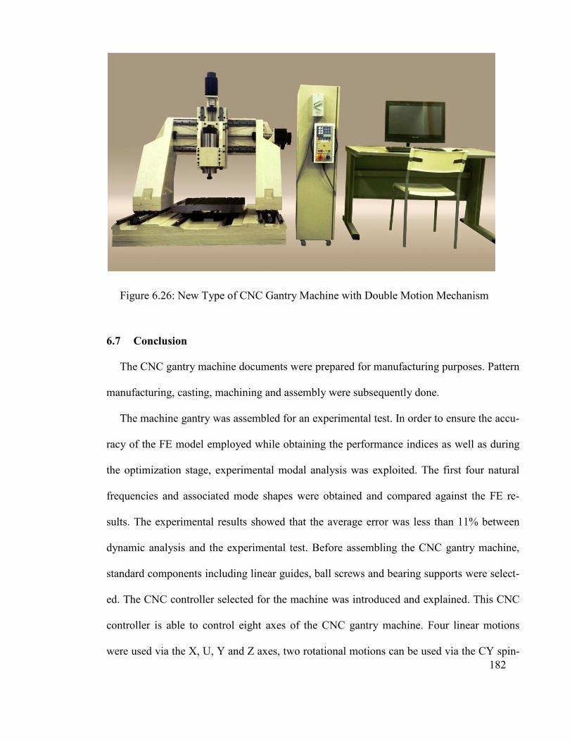
182
Figure 6.26: New Type of CNC Gantry Machine with Double Motion Mechanism
6.7 Conclusion
The CNC gantry machine documents were prepared for manufacturing purposes. Pattern
manufacturing, casting, machining and assembly were subsequently done.
The machine gantry was assembled for an experimental test. In order to ensure the accu-
racy of the FE model employed while obtaining the performance indices as well as during
the optimization stage, experimental modal analysis was exploited. The first four natural
frequencies and associated mode shapes were obtained and compared against the FE re-
sults. The experimental results showed that the average error was less than 11% between
dynamic analysis and the experimental test. Before assembling the CNC gantry machine,
standard components including linear guides, ball screws and bearing supports were select-
ed. The CNC controller selected for the machine was introduced and explained. This CNC
controller is able to control eight axes of the CNC gantry machine. Four linear motions
were used via the X, U, Y and Z axes, two rotational motions can be used via the CY spin-

183
dle if requested for future functions and two extra axes for other requirements. Considering
the machine and CNC controller’s capabilities, the final machine configuration can be
LLLLRR. The CNC controller selected for the machine was introduced. The final thesis
conclusions are discussed in the next chapter.

184
7.1 Conclusion
The CNC gantry machine is presently one of the most valuable machine tools for indus-
trial manufacturing purposes, as it is useful in many fields. The CNC gantry machine is
functional for machining large and long components. Up until now, two such machine
types have been invented. The first type has a moving worktable and fixed gantry while the
second type has a moving gantry and fixed worktable. Both types have advantages and dis-
advantages.
In this study, for improving the specifications and applications of the existing types of
CNC gantry machine, a new, innovative CNC gantry machine has been proposed. The ad-
vantage of the proposed gantry machine is the reciprocal (simultaneous) motion of the gan-
try and worktable, which is called a double motion mechanism.
Initially, the double motion mechanism was designed as a rack and pinion system. Due
to backlash (gear mechanism error), a new anti-backlash gear mechanism comprising three
spur gears and a rack was explained and a nonlinear dynamic system model was introduced
to gain insight into the system’s dynamic behavior. Validity of the concept of eliminating
backlash was examined using Motion Analysis (MA) in Solidworks software. The mesh
stiffness of mated gears and rack-pinion was evaluated with the finite element method and
was considered by solving a motion equation. Assuming that the gear and rack teeth are
rigid and static transmission error is negligible, the total transmission error of the new
mechanism will be near zero.
CAPTER 7
7 THESIS CONCLUSION

185
The minimum amount of preload at which the system remains anti-backlash while oper-
ating was estimated. This depends on applied torque, external load on the rack and varied
mesh stiffness behavior. Total system transmission error was obtained by solving the dif-
ferential equation of motion using the Runge-Kutta method.
However, due to difficulties in manufacturing gear systems, a new double motion
mechanism was proposed with a ball screw system. Three different designs of a new CNC
gantry machine were then proposed.
To evaluate the behavior and modifications of the gantry with desired characteristics,
modal analysis was performed. The gantry’s natural frequency was 102.36 Hz, but it
changed to 131.95 Hz when the material was changed to steel. The results showed that the
gantry was improving.
A modification process was done to increase stiffness. The minimum natural frequency
of the gantry increased slightly to above 200 Hz. The deformation of the CNC machine’s
spindle tip was around 10 microns at 11530 rpm. This modification process increased the
gantry’s weight. The results indicated that the Z-axis position has no significant effect on
the gantry’s dynamic behavior.
The range of machining materials and cutting force was calculated for the selected spin-
dle. According to the static analysis results, cutting force did not have any negative effect
on machining precision. It appeared that the new CNC gantry machine could function at
11,530 rpm in the machining process without a problem. The final design of the new CNC
gantry machine was patented as a special gantry machine of three different types.
After modifying the third gantry machine design, the fourth design was obtained.
186
Since the gantry weight increased during modification, a new crossbeam was designed
to decrease the weight. Hence, a fifth design was proposed by changing the gantry cross-
beam. This design reduced the gantry’s weight by up to 3.8%.
The increasing natural frequency of the gantry during design modification affected
complexity and increased the weight and manufacturing cost of the gantry. For these rea-
sons, five different gantry designs were selected and compared. Four parameters, namely
the first four natural mode frequencies, total deformation under mechanical forces and
weight and manufacturing cost were considered for the comparison. One was selected
among five designs using a mathematical method. The selected design was optimized by
MOGA (multi-objective genetic algorithm) in ANSYS software.
In the optimization process, the gantry’s natural frequency was maximized and total de-
formation against mechanical forces and its weight was minimized.
The CNC gantry machine documents for manufacturing were prepared. Subsequently,
pattern manufacturing, casting, machining and assembly were done, respectively.
To evaluate and verify the design and analysis processes, an experimental test was per-
formed with related instruments. The experimental results indicated that that the average
error was less than 11% between the dynamic analysis and experimental test.
Before assembling the CNC gantry machine, standard components, such as linear
guides, ball screws and bearing supports were selected, after which they were assembled
respectively.
The selected CNC machine controller was introduced and explained. This CNC control-
ler is able to control eight axes of the CNC gantry machine. Four linear motions were used

187
through the X, U, Y and Z axes, two rotational motions will be used via the CY spindle if
requested for future functions and two extra axes can be applied for other requirements. In
light of the capabilities of the machine and CNC controller, the final machine configuration
can be LLLLRR. The controller is a separate project done by a Master’s student at Univer-
sity of Malaya. To control the machine, there are two types of CNC controller (PC- and
PLC-based). A PC-based system, the CENTROID, was chosen for machine control because
it is flexible. Ultimately, the complete, new type of CNC gantry machine was presented in
this study.
7.2 Directions for Future Research
Considering the advantages of the double motion mechanism discussed in this study,
other advantages should be investigated further in future research works. The topics ad-
dressed in this case, such as improving “machine efficiency,” simplifying “machine manu-
facturing,” and decreasing the “total cost” of the machine, need more investigation as well.
In addition, considering the capability of the CNC gantry machine designed and made in
three types, experimentally testing the machining process of the new type (simultaneously
moving gantry and worktable) and comparing the results with other types, is subject to po-
tential, significant new research.
7.3 Future Works
According to the machine tool errors which affected the machining accuracy, such as
geometric and thermal errors, for finding the geometrical errors, the metrological test of the
machine will be needed in the future works. In addition the total thermal errors of spindle

188
of the CNC gantry machine must be evaluated due to the large amounts of the heat, which
is produced by its high-speed revolution.
7.4 Recommendation
Throughout this project, the researcher worked very hard to innovate, design and proto-
type the machine. This is an original type of gantry machine, which will significantly affect
the machining process and CNC gantry machine manufacturing. Therefore, recommends
commercializing this machine.

189
158 JIXIE, Available from: "158jixie.com/news-detail/256/256275.html". Abdel-Malek, et al. . (2000). Algorithm based decision support system for the concerted
selection of equipment in machining/assembly cells. International journal of production research, 38(2), 323-339.
Abdi, M. ( 2009). Fuzzy multi-criteria decision model for evaluating reconfigurable machines. International Journal of Production Economics, 117(1), 1-15.
Allan, et al. (1980). The determination of minimum pre-load torque for anti-backlash gears in a positional servomechanism. IEEE Transactions on Industrial Electronics and Control Instrumentation, 27(1), 26-29.
Altintas, et al. (2011). Machine tool feed drives. Paper presented at the CIRP Annals-Manufacturing Technology.
Altintas, Y. (2000). Manufacturing Automation Cambridge University Press, London, UK 2000.
Andersson, J. (2003). Applications of a multi-objective genetic algorithm to engineering design problems. Paper presented at the Evolutionary Multi-Criterion Optimization.
Arnold, et al. (2001). The recent history of the machine tool industry and the effects of technological change. Münchner Betriebswirtschaftliche Beiträge, 14.
Atlanta Drive Systems Inc. (2013 ). Ultra-High Precision Rack & Pinion Drive Systems Available From: "atlantadrives.com" (Vol. (800) pp. 505-1715).
Ayağ, et al. (2006). A fuzzy AHP approach to evaluating machine tool alternatives. Journal of intelligent manufacturing, 17(2), 179-190.
Ayağ, et al. (2011). An intelligent approach to machine tool selection through fuzzy analytic network process. Journal of intelligent manufacturing, 22(2), 163-177.
Ayağ, Z. ( 2007). A hybrid approach to machine-tool selection through AHP and simulation. International journal of production research, 45(9), 2029-2050.
B. Sencer, et al. (2008). Feed optimization for five-axis CNC machine tools with drive constraints. Machine Tools.
Baker, et al. (2002). Finite Elem. Anal. Des., 38 1029-1046. Baradie, et al. (1991). Statistical theory of machine tool stability. Journal of Engineering
Manufacture 205, 195–206. Be´zier, P. (1972). Numerical Control Mathematics and Applications: Wiley & Sons. Boadway, et al. (1984). Welfare economics: Pablised by "Blackwell Oxford". Bohez, Erik LJ. (2002). Five-axis milling machine tool kinematic chain design and
analysis. International Journal of Machine Tools and Manufacture, 42(4), 505-520. Boyuan, et al. (2001). Drive Chain Return difference analysis and estimate of spring-loaded
anti-backlash Gear. Mechanical Design, 6, 40-42. Brauer, et al. (2003). Investigation of transmission error, friction and wear in anti-backlash
involute gear transmissions: A finite element approach. (C815490 Ph.D.), Kungliga Tekniska Hogskolan (Sweden), Ann Arbor.
Budak, E. (2004). A decision support system for machine tool selection. Journal of Manufacturing Technology Management, 15(1), 101-109.
C. W. Cairnes, Anti-backlash gearing "US Patent 2,663,198, 1953". (1953). C.Yongqing, W. Xunchi. (Jan. 2007). Finite element analysis of 2400t gantry crane.
Construction machinery, 7-73.
REFERENCES

190
Centroid Controler, Available From: "centroidcnc.com/cnc_technology.html". (CNC Controler technology).
Chen, et al. (2000). A ballscrew drive mechanism with piezo-electric nut for preload and motion control. International Journal of Machine Tools and Manufacture, 40(4), 513-526.
Cheng, et al. (2005). Design of a six-axis high precision machine tool and its application in machining aspherical optical mirrors. International Journal of Machine Tools and Manufacture, 45(9), 1085-1094.
Clark, Norman G. Roller Pinion System -- The Linear Drive Alternative corp., Hiwin technologies. (2011). HIWIN "Motion control and System Technology". Dağdeviren, M. (2008). Decision making in equipment selection: an integrated approach
with AHP and PROMETHEE. Journal of intelligent manufacturing, 19(4), 397-406.
Deb, K. (2001). Multi-objective optimization using evolutionary algorithms: John Wiley & Sons Chichester.
Dhupia, et al. (2007). Dynamics of the arch-type reconfigurable machine tool. International Journal of Machine Tools and Manufacture, 47(2), 326-334.
Díaz, et al. (2009). Machines for the Aeronautical Industry Machine Tools for High Performance Machining,Springer, 399-420.
E. Budak, Y. Altintas. (1994). Peripheral milling conditions for improved dimensional accuracy. International Journal of Machine Tools and Manufacture, 34(7), 907-918.
EI Baradie, et al. (1976). Dynamic acceptance tests for horizontal milling machine based on a statistical theory of machine tool chatter. Journal of Engineering for Industry Transactions of ASME, 98(3), 919-929.
EI Baradie, M.A. . (1993). Statistical analysis of the dynamic cutting coefficients and machine tool stability. Journal of Engineering for Industry Transactions of ASME 115, 115(2), 205-215.
Eman, et al. (1983). Modal analysis of machine tool structures based on experimental data. Journal of manufacturing science and engineering, 105(4), 282-287.
Eritenel, et al. (2012). Three-dimensional nonlinear vibration of gear pairs. Journal of Sound and Vibration, 331(15), 3628-3648.
Erkorkmaz, et al. (2010). Precision machine tool X–Y stage utilizing a planar air bearing arrangement. Paper presented at the CIRP Annals - Manufacturing Technology.
Ertuğrul, et al. (2007). Fuzzy Multi-criteria Decision Making Method for Machine Selection. Analysis and Design of Intelligent Systems using Soft Computing Techniques, 41, 638-648.
FJunlian. (2006). Bridge crane girder optimization design based on ANSYS. Science & Technology Association Forum, 21-22.
G-H Tzeng, J-J Huang. (2011). Multi-attribute decision making: methods and applications. CRC Press.
Gill-Jeong, Cheon. (2007). WITHDRAWN: Nonlinear behavior analysis of spur gear pairs with a one-way clutch. Journal of Sound and Vibration, 304(1), 18-30.
Gimenez, et al. (1995). A Step by Step Approach to the Dynamic Behavior of Centreless Grinding Machines. Int. J. Maeh. Tools Manuf, 35(9), 1291-1307.

191
Gordon, et al. (2005). Development of a high-speed CNC cutting machine using linear motors. Journal of Materials Processing Technology, 166(3), 321-329.
Graham, T.Smith. (2008). Cutting tool technology: Published by "Springer". Gregory, et al. (1963). Dynamic behaviour of spur gears. Paper presented at the
Proceedings of the institution of mechanical engineers. Grierson, Donald E. (2008). Pareto multi-criteria decision making. Advanced Engineering
Informatics, 22(3), 371-384. Guan, et al. (2010). Analysis and optimization of crossbeam of gantry machining center.
Paper presented at the Information Engineering and Computer Science (ICIECS), 2010 2nd International Conference on.
Guang-Yuan, et al. (1985). Fuzzy optimum design of structures. Engineering optimization, 8(4), 291-300.
Guoming, L. I. (2001). Calculation and analysis of double gear’s inherent frequency. Electro-Mechanical Engineering, 3, 11-12.
Hale, et al. (1994). Design of anti-backlash transmissions for precision position control systems. Precision Engineering, 16(4), 244-258.
Han, et al. (2011). Structural analysis and optimization on crossbeam of heavy NC gantry moving boring & milling machine. Paper presented at the Electronic and Mechanical Engineering and Information Technology (EMEIT), 2011 International Conference on.
He, et al. (2007). Effect of sliding friction on the dynamics of spur gear pair with realistic time-varying stiffness. Journal of Sound and Vibration, 301(3), 927-949.
Held, M. (1991). A geometry-based investigation of the tool path generation for zigzag pocket machining. The Visual Computer, 7(5-6), 296-308.
Hiwin Company, Available From: "hiwin.com/html/ball%20screws/support_units.html". Hiwin technologies corp, available from "hiwin.com". (2011). Motion control and System
Technology. Holland, J. M. (1975). Adaptation in natural and artificial systems. Ann Arbor. Imasaki, Naoki. (1995). Adaptive control of robot manipulators with anti-backlash gears.
Paper presented at the Robotics and Automation, 1995. Proceedings., 1995 IEEE International Conference on.
IOS. (2001). Industrial automation systems and integration – Numerical control of machines – Coordinate system and motion nomenclature (Vol. International Standard ISO 84).
Jianrun, et al. (2005). Dynamic optimization design of 5 axis numerical control gantry machining center. China Mechanical Engineering, 16(21), 1949-1953.
K Fansen, Y Junyi (1999). Fuzzy dynamic response analysis of machine tool structure International Journal of Machine Tools and Manufacture, 39(12), 1993–2002.
Kahraman, et al. (1991a). Interactions between time-varying mesh stiffness and clearance non-linearities in a geared system. Journal of Sound and Vibration, 146(1), 135-156.
Kahraman, et al. (1991b). Non-linear dynamics of a geared rotor-bearing system with multiple clearances. Journal of Sound and Vibration, 144(3), 469-506.
Khuberyan, et al. (1972). Analysis of the arches of underground powerhouses with crane-supporting beams. Hydrotechnical Construction, 6(4), 376-382.

192
Konak, et al. (2006). Multi-objective optimization using genetic algorithms: A tutorial. Reliability Engineering & System Safety, 91(9), 992-1007.
Koza, J. R. (1992). Genetic programming: on the programming of computers by means of natural selection (Vol. 1): MIT press.
Krishna, V. (2009). Structural optimization using ANSYS classic and radial basis function based response surface models.
Krulewich, Debra A. (1998). Temperature integration model and measurement point selection for thermally induced machine tool errors. Mechatronics, 8(4), 395-412.
Kwon, et al. (2004). Rate loop control based on torque compensation in anti-backlash geared servo system. Paper presented at the American Control Conference, 2004. Proceedings of the 2004.
L.N, et al. (2009). machine tools for high performance machining: Springer press. Lamikiz, et al. (2009). Machine Tool Performance and Precision. In L. N. López de Lacalle
& A. Lamikiz (Eds.), Machine Tools for High Performance Machining (pp. 219-260): Springer London.
Lan, T.-S. (2010). Parametric deduction optimization for surface roughness. American Journal of Applied Sciences, 7(9), 12-48.
Lassâad Walha, et al. (2009). Nonlinear dynamics of a two-stage gear system with mesh stiffness fluctuation, bearing flexibility and backlash. Mechanism and Machine Theory, 44, 1058–1069.
Lee, et al. (2006). Dynamic analysis of a mesoscale machine tool. Journal of manufacturing science and engineering, 128(1), 194-203.
Lei, et al. (2007). Double ballbar test for the rotary axes of five-axis CNC machine tools. International Journal of Machine Tools & Manufacture, 47 273–285.
Li, S. (2007). Finite element analyses for contact strength and bending strength of a pair of spur gears with machining errors, assembly errors and tooth modifications. Mechanism and Machine Theory, 42(1), 88-114.
Lin, et al. (1996). Evaluation of machine selection by the AHP method. Journal of Materials Processing Technology, 57(3), 253-258.
Lin, et al. (2001). CAD-based CMM dimensional inspection path planning – a generic algorithm. Robotica, 19(2), 137-148.
Liu, et al. (1995). Damping Identification of the Mechanical Structural Jiont Surface. Journal of Vibration and Shock, 14 (3), 61-65.
Liu, et al. (2014). Structural optimization of the cross-beam of a gantry machine tool based on grey relational analysis. Structural and Multidisciplinary Optimization, 50, 297-311.
Liu Fang, et al. (2007). Dynamic finite element analysis of the high speed gantry machine center GMC3000[J],. Modern Manufacturing Engineering, 113-116.
LNL de Lacalle, et al. (2009). Machine Tools for Removal Processes: A General View Machine Tools for High Performance Machining, Springer, 1-45 .
Luo, et al. (2006). Design and research of the structural of cross-rail in the planer type machines. Mech Electr Eng Technol, 35(3), 45-47.
Macrotec Machine tools LTD, Available from. google.com.my/?gws_rd=cr&ei=e0U1VKuTC4WSuAT9jIJ4#q=Macrotec+Machine+tools+LTD.
193
Maia, et al. (1997). Theoretical and Experimental Modal Analysis (John Wiley & Sons, New York, NY, USA 1997 ).
Majid, Kamal Izeldeen. (1974). Optimum design of structures. Mayr, et al. (2014). Cutting Fluid Influence on Thermal Behavior of 5-axis Machine Tools.
Paper presented at the Procedia CIRP. Ming, et al. (2010, 26-28 June 2010). Influence of different boundary constraint in static
and dynamic analysis. Paper presented at the Mechanic Automation and Control Engineering (MACE), 2010 International Conference on.
Moradi, et al. (2012). Analysis of nonlinear oscillations in spur gear pairs with approximated modelling of backlash nonlinearity. Mechanism and Machine Theory, 51, 14-31.
Myers, A. (2005). Measurement techniques for determining the static stiffness of foundations for machine tools. Journal of Physics, 13, 410–413.
Nevzat Özgüven, et al. (1988). Mathematical models used in gear dynamics—a review. Journal of Sound and Vibration, 121(3), 383-411.
Newmana, et al. (2008 ). Strategic advantages of interoperability for global manufacturing using CNC technology. Robotics and Computer-Integrated Manufacturing, 24 699– 708.
Ni Xiangyang, et al. (2005). features analysis of 5 axis numerical control gantry machining center[J]. Precision with the automation, 12-16.
Nsk Ltd. (2013). Patent Application Titled "Rack and Pinion Steering Gear Unit" Under Review. NewsRx, Atlanta. ABI/INFORM Complete database.
O. Durán, J. Aguilo. (2008). Computer-aided machine-tool selection based on a Fuzzy-AHP approach. Expert Systems with Applications, 34(3), 1787-1794.
Önüt, et al. (2008). A hybrid fuzzy MCDM approach to machine tool selection. Journal of intelligent manufacturing, 19(4), 443-453.
Padmanabhan, et al. (1996). Analysis of periodically forced nonlinear Hill’s oscillator with application to a geared system. The Journal of the Acoustical Society of America, 99(1), 324-334.
Patwari, et al. (2010). Dynamic modal analysis of vertical machining centre components. Advances in Acoustics and Vibration.
Pedrammehr, et al. (2012). Modal analysis of the milling machine structure through FEM and experimental test. Advanced Materials Research, 383, 6717-6721.
Qi, J.. (2010). Machine tool selection model based on fuzzy MCDM approach. In,. IEEE, 282-285.
R. Kalantari, M. Saadat Foomani. (2009). Backlash Nonlinearity Modeling and Adaptive Controller Design for an Electromechanical Power Transmission System. Sharif University of Technology, 16, 463-469.
Ra Jeev S. (2003). Vibration analysis of machine tool structure. Paper presented at the VIII International Conference on Recent Advances in Structure Dynamics, Southampton, UK.
Rahman, et al. ( 2001.Bazul,). Non-conventional materials for machine tool structures. Int. J. JSME., 44: 1-11, DOI: 10.1299/jsmec.44.1.
Rao, S. S. (2009). Engineering optimization: theory and practice: John Wiley & Sons. Rechenberg, Evolutionsstrategie. (1973). Optimierung technischer Systeme nach Prinzipien
der biologischen Evolution. Frommann-Holzboog Verlag, Stuttgart.

194
Reuleaux. (2007). Theoretische Kinematik. Verlag Dr. Müller. S. Haranath, et al. (1987). Dynamic analysis of machine tool column with layer finite
element approach. International Journal of Machine Tools and Maunfacture, 27-41. S. R. Besharati, et al. (2012). Malaysia Patent No. PI 2012 701279. Patent title "Gear
Backlash Compensation Mechanism (GBCM) in Rack and Pinion System", UMCIC.
S. R. Besharati, et al. (2013). Malaysia Patent No. PI 2013 001205 Patent title "A Newly Efficient, Accurate and Precision CNC Gantry Machine with Double Motion", UMCIC.
S. R. Besharati, et al. (2014). Malaysia Patent No. PCT: UM.TNC2/UMCIC/603/536. Patent title "A Newly Efficient, Accurate and Precision CNC Gantry Machine with Double Motion", UMCIC.
S. R. Besharati, M. Hamdi. (2011). Malaysia Patent No. PI 2011700176. Patent title "CNC Double Motion Gantry Machine", UMCIC.
Saaty, T. L. (1980). The analytic hierarchy process New York: McGraw-Hill. Sematech. (1997). Computer Integrated Manufacturing (CIM) Application Framework
Specification 2706 Montopolis Drive, Austin, TX 78741 U.S.A (Vol. 7, pp. 17-21). Shevchuk, S.A. (2008). Cast iron in machine tools. Russian. Eng. Rese., 29, 901-903. Shibly, H. A. (1988). Performance evaluation and efficient control of trajectory following
robots with friction and backlash. (Volumes I and II). (8813721 Ph.D.), Carnegie Mellon University, Ann Arbor. ProQuest Dissertations & Theses Full Text database.
Shim, et al. (2008). Reduction of PTO rattle noise of an agricultural tractor using an anti-backlash gear. Biosystems engineering, 100(3), 346-354.
Shubo Xu, et al. ( 2010). Study on Modeling Simulation of Long-span Gantry NC Machining Center Structure. International Conference of Digital Manufacturing & Automation.
Sorokin, et al. (2001). Analysis and optimization of energy flows in structures composed of beam elements–Part I: problem formulation and solution technique. Structural and Multidisciplinary Optimization, 22(1), 3-11.
Stamper, et al. (1997). Optimization of a three DOF translational platform for well-conditioned workspace. Paper presented at the Robotics and Automation.
Stecke, K. E. (1983). Formulation and solution of nonlinear integer production planning problems for flexible manufacturing systems. Management Science, 29(3), 273-288.
T. Murakami, et al. (2006). Damping and tribological properties of Fe–Si–C cast iron prepared using various heat treatments. Materials Science and Engineering, 2006, 113 - 119.
Taha, et al. (2012). A hybrid fuzzy AHP-PROMETHEE decision support system for machine tool selection in flexible manufacturing cell. Journal of intelligent manufacturing, 23(6), 2137-2149.
Taha, et al. ( 2011 ). A fuzzy AHP-ANN-based decision support system for machine tool selection in a flexible manufacturing cell. The International Journal of Advanced Manufacturing Technology, 57(5-8), 719-733.
Teo, et al. (2007). Dynamic modeling and adaptive control of a H-type gantry stage. Mechatronics, 17, 361–367.
THK A-679, Available from "THK.com". (2014). Ballscrew General Catalog.
195
Tlusty, M. Polacek. (1963). Proceedings of the ASME International Research in Production Engineering. Pittsburgh, USA, 465-474.
Tobias, S.A. . (1965). Machine Tool Vibration. Wiley New York. Tomasent, Availabl from: . "news.thomasnet.com/fullstory/CNC-Machining-Finishing-
System-offers-5-axis-flexibility-565843" Tsann-Huei Chang, et al. (2004). US 10/011,487. Patent title" Gantry type hybrid parallel
linkage five-axis machine tool". Van Dooren, R. (2001). Comments on non-linear dynamics of gear-pair systems with
periodic stiffness and backlash. Journal of Sound and Vibration, 244(5), 899-903. Verl, et al. (2014). Double nut ballscrew with improved operating characteristics. CIRP
Annals - Manufacturing Technology, 63(1), 361-364. W.T. Lei, Y.Y. Hsu. (2002). Accuracy test of five-axis CNC machine tool with 3D probe–
ball. Part I: design and modeling. International Journal of Machine Tools & Manufacture, 42, 1153–1162.
Wang, et al. (2003). Survey of nonlinear vibration of gear transmission systems. Applied Mechanics Reviews, 56(3), 309-329.
Wang, et al. (2007). Dynamics of a hypoid gear pair considering the effects of time-varying mesh parameters and backlash nonlinearity. Journal of Sound and Vibration, 308(1), 302-329.
Wang XY, et al. (2009). The topological optimization design and analysis for gantry machine tool crossbeam component. Manuf Technol Mach Tool, 56(11), 64–67.
Weule, et al. (2003). Structural Optimization of Machine Tools including the static and dynamic Workspace Behavior. Paper presented at the The 36th cirp-international seminar on manufacturing systems.
Wu, et al. (2003). Thermal analysis for the feed drive system of a CNC machine center. International Journal of Machine Tools and Manufacture, 43(15), 1521-1528.
Xiuheng, et al. (2010). Structural Optimization on Beam Parts of Bridge Type Five Axis Linkage Gantry Machining Center. Paper presented at the Intelligent Networks and Intelligent Systems (ICINIS), 2010 3rd International Conference on.
Xu, et al. (2006). Making CNC machine tools more open, interoperable and intelligent—a review of the technologies. Computers in Industry, 57 141–152.
Y. Guan, et al. (2010). Finite Element Analysis of Five-Axis Gantry Milling Machine Main Structure. International Conference on E-Product E-Service and E-Entertainment (ICEEE),, 1-4.
Y.T. Ic, et al. (2012). Development of a component-based machining centre selection model using AHP.
Y.T. İç, M. Yurdakul. ( 2009). Development of a decision support system for machining center selection. Expert Systems with Applications, 36(2), 3505-3513.
Yanhua, S. (2009). Beam Parts Dynamic Characteristic Analyse of GS5200 Gantry Five-face Machining Center. Manufacturing Technology & Machine Tool, 5, 32.
Z. Ayağ, et al. ( 2006). A fuzzy AHP approach to evaluating machine tool alternatives. Journal of intelligent manufacturing, 17(2), 179-190.
Z. Taha, S. Rostam. ( 2011). A hybrid fuzzy AHP-PROMETHEE decision support system for machine tool selection in flexible manufacturing cell. Journal of intelligent manufacturing, 1-13.

196
Z.Dewen, et al. (2006). Bridge type crane girders deflection analysis based on the finite element method. Water transportation science research,, A-7.
Zhang, et al. (1996). The theory of response analysis of fuzzy stochastic dynamical systems with a single degree of freedom. Science Press.
Zhao, et al. (2008). Structural bionic design for high-speed machine tool working table based on distribution rules of leaf veins. SCIENCE CHINA Technological Sciences, 55(8), 2091-2098.
Zhao, et al. (2011). Lightweight Design and Verification of Gantry Machining Center Crossbeam Based on Structural Bionics. Journal of Bionic Engineering, 8(2), 201-206.
Zrnić, et al. (2014). Dynamic responses of a gantry crane system due to a moving body considered as moving oscillator. Archives of Civil and Mechanical Engineering(0).

197
No. Appendix No. Subjects Page No.
1. Appendix A All drawings of the CNC gantry machine
design with overall dimensions
A1- A16
2. Appendix B Quality control report from the casting
process by SIRIM Company
B1- B9
3. Appendix C Quality control report from the machining
process by TPM Company
C1- C9
4. Appendix D Drawing of CNC gantry machine assem-
bly
D1- D6
5. Appendix E Quality control reports from assembly and
alignment process by TPM
E1- E-5
6. Appendix F -Detail specifications of standard compo-
nents and calculation
-Servomotor detail specifications
-Spindle detail specifications
F1- F4
7. Appendix G General information G1- G3
APPENDICES
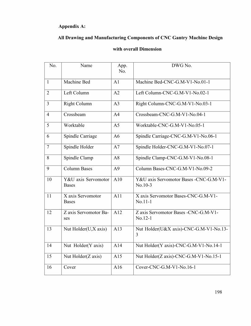
198
Appendix A:
All Drawing and Manufacturing Components of CNC Gantry Machine Design
with overall Dimension
No. Name App. No.
DWG No.
1 Machine Bed A1 Machine Bed-CNC-G.M-V1-No.01-1
2 Left Column A2 Left Column-CNC-G.M-V1-No.02-1
3 Right Column A3 Right Column-CNC-G.M-V1-No.03-1
4 Crossbeam A4 Crossbeam-CNC-G.M-V1-No.04-1
5 Worktable A5 Worktable-CNC-G.M-V1-No.05-1
6 Spindle Carriage A6 Spindle Carriage-CNC-G.M-V1-No.06-1
7 Spindle Holder A7 Spindle Holder-CNC-G.M-V1-No.07-1
8 Spindle Clamp A8 Spindle Clamp-CNC-G.M-V1-No.08-1
9 Column Bases A9 Column Bases-CNC-G.M-V1-No.09-2
10 Y&U axis Servomotor Bases
A10 Y&U axis Servomotor Bases -CNC-G.M-V1-No.10-3
11 X axis Servomotor Bases
A11 X axis Servomotor Bases-CNC-G.M-V1-No.11-1
12 Z axis Servomotor Ba-ses
A12 Z axis Servomotor Bases -CNC-G.M-V1-No.12-1
13 Nut Holder(U,X axis) A13 Nut Holder(U&X axis)-CNC-G.M-V1-No.13-3
14 Nut Holder(Y axis) A14 Nut Holder(Y axis)-CNC-G.M-V1-No.14-1
15 Nut Holder(Z axis) A15 Nut Holder(Z axis)-CNC-G.M-V1-No.15-1
16 Cover A16 Cover-CNC-G.M-V1-No.16-1

215
Appendix B:
Report of Quality Control of Casting Process (from SIRIM Company)
No. Name App. No.
DWG No.
1 Base X B1 Machine Bed-CNC-G.M-V1-No.01-1
2 Test B2 Left Column-CNC-G.M-V1-No.02-1
3 Test2 B3 Right Column-CNC-G.M-V1-No.03-1
4 MD1 B4 Crossbeam-CNC-G.M-V1-No.04-1
5 Y beam Base B5 Worktable-CNC-G.M-V1-No.05-1
6 MD2XT B6 Spindle Carriage-CNC-G.M-V1-No.06-1
7 MD3-2 B7 Spindle Holder-CNC-G.M-V1-No.07-1
8 MD3 B8 Spindle Clamp-CNC-G.M-V1-No.08-1
9 G1-1&G1-2 B9 Column Bases-CNC-G.M-V1-No.09-2

241
Appendix C:
Report of Quality Control from Machining Process by TPM (Technology Park Ma-
laysia)
No. Name App. No.
DWG No.
1 Machine Bed C1 Machine Bed-CNC-G.M-V1-No.01-1
2 Left Column C2 Left Column-CNC-G.M-V1-No.02-1
3 Right Column C3 Right Column-CNC-G.M-V1-No.03-1
4 Crossbeam C4 Crossbeam-CNC-G.M-V1-No.04-1
5 Worktable C5 Worktable-CNC-G.M-V1-No.05-1
6 Spindle Carriage C6 Spindle Carriage-CNC-G.M-V1-No.06-1
7 Spindle Holder C7 Spindle Holder-CNC-G.M-V1-No.07-1
8 Spindle Clamp C8 Spindle Clamp-CNC-G.M-V1-No.08-1
9 Column Bases C9 Column Bases-CNC-G.M-V1-No.09-2
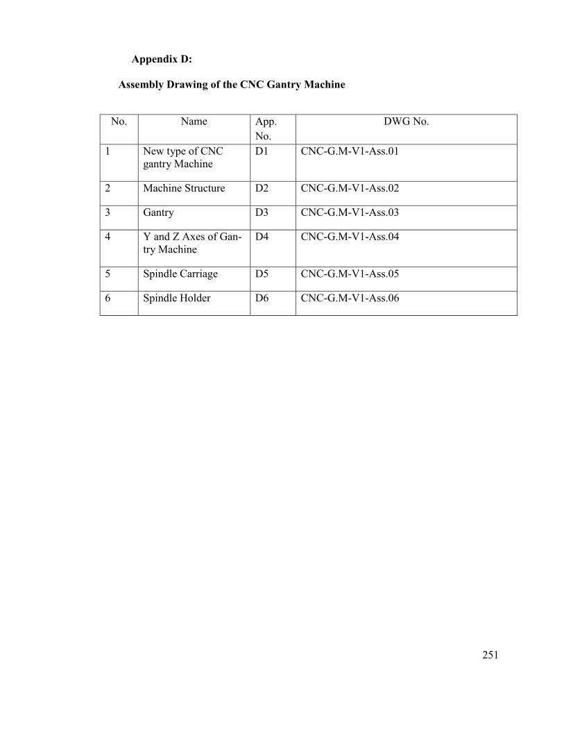
251
Appendix D:
Assembly Drawing of the CNC Gantry Machine
No. Name App.
No.
DWG No.
1 New type of CNC gantry Machine
D1 CNC-G.M-V1-Ass.01
2 Machine Structure D2 CNC-G.M-V1-Ass.02
3 Gantry D3 CNC-G.M-V1-Ass.03
4 Y and Z Axes of Gan-try Machine
D4 CNC-G.M-V1-Ass.04
5 Spindle Carriage D5 CNC-G.M-V1-Ass.05
6 Spindle Holder D6 CNC-G.M-V1-Ass.06

258
Appendix E:
Report of Quality Control from Assembly and Alignment Process by TPM (Tech-
nology Park Malaysia)
No. Name App.
No.
DWG No.
1 Q.C. 1 E1 Ballscrew Alignment
2 Q.C. 2 E2 Linear guides Alignment
3 Q.C. 3 E3 Squareness X-Y
4 Q.C. 4 E4 Squareness X-Z

263
Appendix F:
Specifications and Calculation of Standard CNC Machine Components
No. Name App.
No.
DWG No.
1 List of the components
F1 Standard components
2 Calculation F2 Applied load of linear guide
3 Specification F3 End support (BK)
4 Specification F4 End support (BF)
5 Specification F5 Servomotor

264
Standards CNC Gantry Machine Components
Name Specification quantity documents
Servomotor Delta type 4 Attachment
Spindle Up to 24000
RPM 1 Attachment
Linear guide X axis 28/1150 1 Attachment
Linear guide U axis 23/1150 2 Attachment
Linear guide Y axis 23/700 1 Attachment
Linear guide Z axis 23/510 1 Attachment
Ballscrew X axis 20/760 1 Attachment
Ballscrew U axis 20/995 2 Attachment
Ballscrew Y axis 20/636 1 Attachment
Ballscrew Z axis 20/470 1 Attachment
Flexible Coupling 16/48 5 standard
Bearing BK -15 5 Attachment
Bearing Bf -15 5 Attachment
M8 L=40 28 Structure linearguide
M6 L=30 76 Gantry linearguide
M6 L=50 6 Workable bearings
M6 L=50 12 Gantry bearings
M8 L=40 12 For lock linear
M8 L=35 12 Motor brackets

265
M8 L=25 20 Motors
M6 L=25 24 For lock linear
M12 L=80 28 Crossbeam to columns
M12 L=95 12 Columns to base
M12 L=80 8 Columns to base
M12 L=60 8 Columns to base
M10 L=65 4 Gantry motor Bracket
M6 *** L=20 16 Crossbeam lock
M6 L=30 24 Crossbeam linearguide
M6 L=50 6 Crossbeam bearing
M6 L=25 32 Crossbeam lock
M6 L=30 18 Y axis linear
M8 L=50 16 Y axis linear block
M8 L=55 4 Y axis nut holder
M6 L=30 6 Y axis nut
M6 L=50 6 Y axis bearing
M8 L=30 4 Y axis motor bracket
M6 L=25 8 Y axis linear lock
M4 L=15 16 Lock linear
M8 L=40 16 Z axis linear block
M8 L=50 4 Z axis nut holder
M6 L=30 6 Z axis nut

266
M6 L=25 8 Z axis linear lock
M8 L=55 8 Spindle holder
M8 L=45 32 Base linear block
M10 L=60 8 Base nut holder
M6 L=25 16 Base lock block
M6 L=30 16 Base lock block
M6 *** L=15 16 Base lock block
M10 L=65 16 Worktable linear block
M10 L=70 4 Worktable Nut holder
M6 L=30 6 Nut to holder
M10 30 12 Lock linear columns
Lifting eye bolt
M12 4 structure
Lifting eye bolt
M10 2 Y axis body
Lifting eye bolt
M12 2 crossbeam
Lifting eye bolt M12 2 gantries
Lifting eye bolt M10 1 Z axis body
Lock linear D=11 12 Worktable linear
Lock linear D=9 12 Y axis linear
Pine d=10 L=50 4 Spindle holder

267
Applied load of linear guide
The applied load of linear guide of CNC gantry X axis motion have been calculated in
the following as an example to verifying of selected standard LM guides. The Figure 1 is
shown the X axis LM guide installation schematic. This is radial condition of installation of
LM guides and CNC gantry machine worktable will be considered for the evaluation pro-
cess. The Figure 2 is shown real dimension of the X axis LM position. The requirement in-
formation of calculation is shown if Table 1. Two types of linear guide have selected for
this machine “RGW25CC”, “RGW30CC” of rolling circulation system type from HIWIN
Company (Table 2)
Figure 1: The X axis LM guide installation schematic

268
Figure 2: Linear guide positions
Table 1: Requirement Information for Calculation
Options Abb. Z axis Y axis X axis U axis
Table Mass m1 52kg 66kg 103 kg 627kg
Work Mass m2 15kg 52kg 20 kg -
Stroke length ls 300mm 500mm 600 mm 600 mm
Maximum
speed V max 0.2m/s 0.2m/s 0.2m/s 0.2m/s
Acceleration
time t1 0.15s 0.15s 0.15s 0.15s
Deceleration
time t3 0.15s 0.15s 0.15s 0.15s

269
1- The applied load (radial direction) can be obtained via Eq. (7.1). Where, m1=103,
m2=20, V=0.2 m/s, t1, t3=0.15s, t2=2.7, acceleration a1=10 m/s2 , a3=1.333 m/s2, ls= 600
mm. According Figure 2, l0=469 mm, l1=292 mm, l2=150 mm, l3=100 mm, l4=85(61) mm,
l5=155.
�1 = +���
�−
�����
���+
�����
���+
���
�= 337.1 (7.1 a)
�2 = +���
�+
�����
���+
�����
���+
���
�= 666.5 (7.1 b)
�3 = +���
�+
�����
�×��−
�����
���+
���
�= 313.9 (7.1 c)
P3 = +���
�−
�����
�×��−
�����
���+
���
�= −15.5 (7.1 d)
2- The applied load (radial direction) during leftward acceleration can be obtained via
Eq. (7.2):
���� = �� −��×��×��
�×��−
������
���= 153.9 (7.2 a)
���� = �� +������
���+
������
���= 849.7 (7.2 b)
���� = �� +������
���+
������
���= 497.1 (7.2 c)
���� = �� −��×��×��
�×��−
������
���= 198.7 (7.2 d)
3- The applied load (lateral direction) can be obtained via Eq. (7.3):
����� = −��×��×��
�×��= −170.2 (7.3 a)
����� = +������
���= 170.2 (7.3 b)
����� = +������
���= 170.2 (7.3 c)
����� = −��×��×��
�×��= −170.2 (7.3 d)

270
4- The applied load (lateral direction) during leftward acceleration can be obtained via
Eq. (7.4):
���� = �1 +������
���+
������
���= 362.1 (7.4 a)
���� = �2 −��×��×��
�×��−
������
���= 642.2� (7.4 b)
���� = �3 −��×��×��
�×��−
������
���= 289.6� (7.4 c)
���� = �4 +������
���+
������
���= 8.8� (7.4 d)
5- The applied load (lateral direction) via Eq. (7.5):
����� = +������
���= +14.6 (7.5 a)
����� = −��×��×��
�×��= −14.6 (7.5 b)
����� = −��×��×��
�×��= −14.6 (7.5 c)
����� = +������
���= +14.6 (7.5 d)
6- The applied load (lateral direction) during rightward acceleration can be obtained via
Eq. (7.6):
���� = �1 +������
���+
������
���= 361.4 (7.6 a)
���� = �2 −��×��×��
�×��−
������
���= 642.2 (7.6 b)
���� = �3 −��×��×��
�×��−
������
���= 289.6 (7.6 c)
���� = �4 +������
���+
������
���= 8.8 (7.6 d)
7- The applied load (lateral direction) during rightward acceleration can be obtained via
Eq. (7.7):

271
����� = +������
���= +109.8 (7.7 a)
����� = −��×��×��
�×��= −109.8 (7.7 b)
����� = −��×��×��
�×��= −109.8 (7.7 c)
����� = +������
���= +109.8 (7.7 d)
8- The applied load (radial direction) during rightward acceleration can be obtained via
Eq. (7.8):
���� = �1 −��×��×��
�×��−
������
���= 312.8 (7.8 a)
���� = �2 +������
���+
������
���= 690.8 (7.8 b)
���� = �3 +������
���+
������
���= 338.2 (7.8 c)
���� = �4 −��×��×��
�×��−
������
�×��= −39.8 (7.8 d)
9- The applied load (lateral direction) can be obtained via Eq. (7.9):
����� = −��×��×��
�×��= −109.8 (7.9 a)
����� = +������
���= +109.8 (7.9 b)
����� = +������
���= +109.8 (7.9 c)
����� = +������
�×��= −109.8 (7.9 d)
10- Combined radial and thrust load (during uniform motion) can be obtained:
PE1=P1=337.1N
PE2=P2=666.5N
PE3=P3=313.9N

272
PE4=P4=15.5N
11- Combined radial and thrust load (during leftward acceleration) can be obtained via
Eq. (7.10):
PEla1=|Pla1|+|Ptla1|=624.1N (7.10 a)
PEla2=|Pla2|+|Ptla2|=1019.9N (7.10 b)
PEla3=|Pla3|+|Ptla3|=667.3N (7.10 c)
PEla4=|Pla4|+|Ptla4|=368.9N (7.10 d)
12- Combined radial and thrust load (during leftward acceleration) can be obtained via
Eq. (7.11):
PEld1=|Pld1|+|Ptld1|=376.7N (7.11 a)
PEld2=|Pld2|+|Ptld2|=656.8N (7.11 b)
PEld3=|Pld3|+|Ptld3|=301.2N (7.11 c)
PEld4=|Pld4|+|Ptld4|=23.4N (7.11 d)
13- Combined radial and thrust load (during rightward acceleration) can be obtained via
Eq. (7.12):
PEra1=|Pra1|+|Ptra1|=471.2N (7.12 a)
PEra2=|Pra2|+|Ptra2|=752N (7.12 b)
PEra3=|Pra3|+|Ptra3|=399.4N (7.12 c)
PEra4=|Pra4|+|Ptra4|=118.6N (7.12 d)
14- Combined radial and thrust load (during rightward acceleration) can be obtained via
Eq. (7.13):
PErd1=|Prd1|+|Ptrd1|=422.6N (7.13 a)
PErd2=|Prd2|+|Ptrd2|=800.6N (7.13 b)

273
PErd3=|Prd3|+|Ptrd3|=448N (7.13 c)
PErd4=|Prd4|+|Ptrd4|=149.6N (7.13 d)
15- The average load of each linear guide can be obtained via Eq. (7.14):
������
���
�× (�����
� × �� + ���� × �� + �����
� × �� + ������ × �� + ���
� × �� +
������ × ��) = 359.3 (7.14 a)
������
���
�× (�����
� × �� + ���� × �� + �����
� × �� + ������ × �� + ���
� × �� +
������ × ��) = 686.3 (7.14 b)
������
���
�× (�����
� × �� + ���� × �� + �����
� × �� + ������ × �� + ���
� × �� +
������ × ��) = 341.3 (7.14 c)
������
���
�× (�����
� × �� + ���� × �� + �����
� × �� + ������ × �� + ���
� × �� +
������ × ��) = 111.2 (7.14 d)

274
Table 2: The RGW-CC/RGW-HC Series of Linear Guides(corp., 2011)

278
Appendix G:
Optimization Methods:
The ANSYS Design Xplorer offers the following Goal Driven Optimization methods
Method Description Response
Surface Optimi-zation
Direct Op-timization
Screening Shifted-Hammersley Sampling X X
NLPQL Nonlinear Programming by Quad-
ratic Lagrangian X X
MISQP Mixed-Integer Sequential Quadratic
Programming X X
MOGA Multi-Objective Genetic Algorithm X X
Adaptive Single-Objective
Hybrid optimization method using Latin Hypercube Sampling, a Kriging response surface, NLPQL and domain reduction in a Direct Optimization sys-tem
X
Adaptive Multiple-Objective
Hybrid optimization method using a Kriging response surface and MOGA in a Direct Optimization system
X
Performing a Screening Optimization
The Screening option can be used for both Response Surface Optimization and Direct
Optimization. It allows you to generate a new sample set and sort its samples based on ob-
jectives and constraints. It is a non-iterative approach that is available for all types of input
parameters. Usually the Screening approach is used for preliminary design, which may lead
you to apply the MOGA or NLPQL options for more refined optimization results.
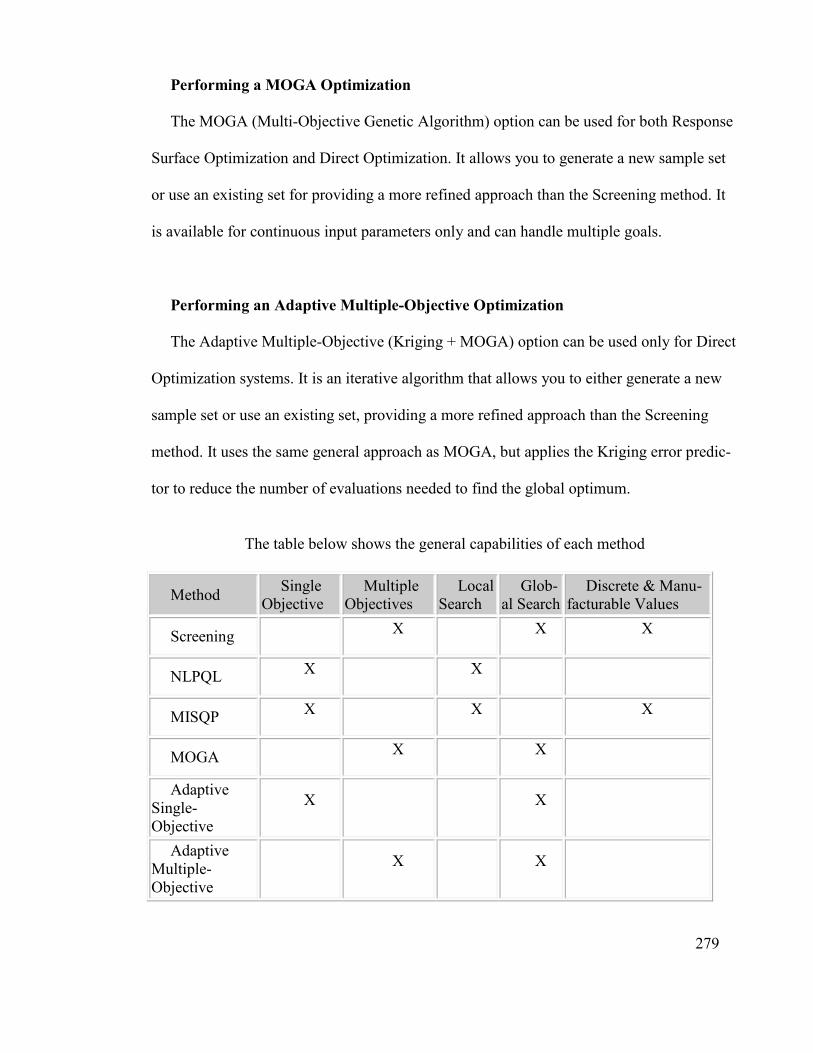
279
Performing a MOGA Optimization
The MOGA (Multi-Objective Genetic Algorithm) option can be used for both Response
Surface Optimization and Direct Optimization. It allows you to generate a new sample set
or use an existing set for providing a more refined approach than the Screening method. It
is available for continuous input parameters only and can handle multiple goals.
Performing an Adaptive Multiple-Objective Optimization
The Adaptive Multiple-Objective (Kriging + MOGA) option can be used only for Direct
Optimization systems. It is an iterative algorithm that allows you to either generate a new
sample set or use an existing set, providing a more refined approach than the Screening
method. It uses the same general approach as MOGA, but applies the Kriging error predic-
tor to reduce the number of evaluations needed to find the global optimum.
The table below shows the general capabilities of each method
Method Single
Objective Multiple
Objectives Local
Search Glob-
al Search Discrete & Manu-
facturable Values
Screening X X X
NLPQL X X
MISQP X X X
MOGA X X
Adaptive Single-Objective
X X
Adaptive Multiple-Objective
X X