design and manufacturing directional drilling team 15
TRANSCRIPT

Page 1
College of Engineering
Department of Mechanical Engineering
Spring 2018-2019
Senior Design Project Report
Design and Manufacturing Directional Drilling
In partial fulfilment of the requirements for the Degree of
Bachelor of Science in Mechanical Engineering
Team 15
Team Members
Student Name ID
Mutab Alshmmari 201600336
Nayef Alfaleh 201500173
Nawaf Alhammad 201300405
Fayed Ibrahim 201502046
Project Advisor:
Advisor Name: Dr. Panos Sphicas
Page 2
Abstract
Oil industry is one of the biggest sectors in Saudi Arabia. There are many leading drilling
companies consider Saudi Arabia as their main client. However, exploration drilling is one of
the main concerns for those companies. Due to depth of drilling and limitations on changing
drilling direction, exploration drilling is very challenging. Our prototype will try to find a
solution to direct the drill bit with an angle while drilling without the need to pull out BHA.
We will implement the concepts of Fluid Dynamics in order to control the angle and maintain
it. The changing of angle can be done through using a piston will be connected to the drilling
pipe. The piston helps to bend the drilling pipe with certain forces that will make the drill bit
bends as well in the other direction. By controlling the force of piston, we can control
bending angle of the drill bit.

Page 3
Acknowledgments
First of all, we would like to express our appreciation to all those who provided us the
possibility to complete this project. A kindly appreciation to senior project advisor Dr. Panos
Sphicas for his continued support for our project and his sincere encouragement and
suggestions.
Moreover, we would like also to acknowledge with much appreciation to the faculty of
Mechanical Engineering Department at Prince Mohammed Bin Fahd University who were
interested in helping us to proceed.
Finally, Special thanks go to our team Muteb Alshmmari*, Nayef Alfaleh, Nawaf Alhammad
and Fayed Ibrahim, whom participating with high protentional and ultimate energy to build
Directional Drilling.
Page 4
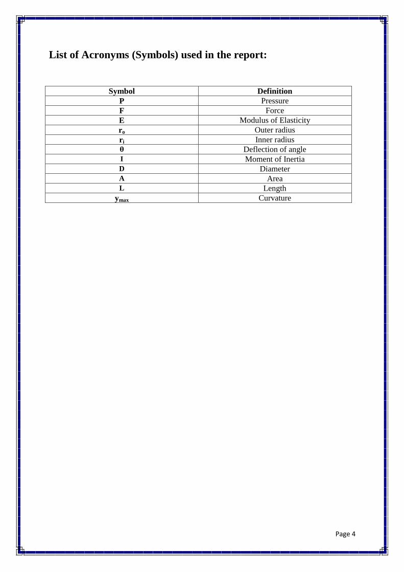
List of Acronyms (Symbols) used in the report:
Symbol Definition
P Pressure
F Force
E Modulus of Elasticity
ro Outer radius
ri Inner radius
Deflection of angle
I Moment of Inertia
D Diameter
A Area
L Length
ymax Curvature

Page 5
List of Figures:
Figure 2.1: Whipstock..............................................................................................................12
Figure 2.2: Bent points ...................................................................................................................... 15
Figure 2.3: How motor work.................................................................................................. 16
Figure 2.4: Methods of RSS................................................................................................... 18
Figure 2.5: How RSS work.................................................................................................... 19
Figure 2.6: Function of Drill Pipe...........................................................................................23
Figure 2.7: Component of inside Drill Pipe.......................................................................... 23
Figure 3.1: Exploded assembly of the system...................................................................... 30
Figure 4.1: Tape measure ...................................................................................................... 34
Figure 4.2: Leisner pointer.................................................................................................... 34
Figure 4.3: Ruler ................................................................................................................... 34
Figure 4.4: Board .................................................................................................................. 35
Figure 4.5: Force in different direction with same angle acting a
point........................................................................................................................................ 36
Figure 4.6: Graph of Force Vs Angle……………………………........................................ 37
Figure 4.7: Graph of Force Vs
Pressure…………………………….......................................................................................38

Page 6
List of Tables:
Table 1.1: The system measurements .................................................................................. 10
Table 3.1: Engineering Standards ........................................................................................ 27
Table 3.2: Pictures of components....................................................................................... 33
Table 4.1: Calculation Force................................................................................................ 37
Table 4.2: Calculation Pressure..............................................................................................30
Table 5.1: Tasks and their durations .................................................................................... 39
Table 5.2: Tasks and assigned members .............................................................................. 40
Table 5.3: Tasks the contribution of the members................................................................41
Table 5.4: Dates of the activates and events.........................................................................42
Table 5.5: Bill of materials .................................................................................................. 43

Page 7
Table of Contents
Abstract ............................................................................................................................. 2
Acknowledgments................................................................................................................. 3
List of Acronyms (Symbols) used in the report: .................................................................... 4
List of Figures: ...................................................................................................................... 5
List of Tables: ....................................................................................................................... 6
Chapter 1: Introduction ......................................................................................................... 9
1.1 Project Objectives .................................................................................................. 10
1.2 Project Specifications ............................................................................................ 10
1.3 Applications ........................................................................................................ 11
Chapter 2: Literature Review .............................................................................................. 12
2.1 Project background .............................................................................................. 12
2.2 Previous Work ..................................................................................................... 20
Chapter 3: System Design ................................................................................................... 25
3.1 Design Constraints and Design Methodology ...................................................... 25
3.2 Engineering Design standards .............................................................................. 26
3.3 Theory and Theoretical Calculations .................................................................... 28
3.4 Product Subsystems and selection of Components ............................................... 29
3.5 Manufacturing and assembly (Implementation) ................................................... 29
Chapter 4: System Testing and Analysis.............................................................................. 34
4.1 Tools……………………………………………………………..................................... 34
4.2 Calculation………………………. ................................................................................... 35
4.3 Procedure……………………….……………………………………………………… 36
4.4 Results…………………………………………………………………………………… 37
Chapter 5: Project Management .......................................................................................... 40
5.1 Project Plan ......................................................................................................... 40
5.2 Contribution of Team Members ........................................................................... 41
5.3 Project Execution Monitoring .............................................................................. 42
5.4 Challenges and Decision Making ......................................................................... 42
5.5 Project Bill of Materials and Budget .................................................................... 43
Chapter 6: Project Analysis ................................................................................................ 44
6.1 Life-long Learning ................................................................................................. 44

Page 8
6.2 Impact of Engineering Solutions ........................................................................... 45
6.3 Contemporary Issues Addressed .......................................................................... 46
Chapter 7: Conclusions and Future Recommendations ........................................................ 47
7.1 Conclusions ......................................................................................................... 47
7.2 Future Recommendations .................................................................................... 47
8. References ............................................................................................................... 48
Appendix A: Progress Reports ............................................................................................ 50
Appendix B: Engineering standards (Local and International) ............................................. 56
Appendix C: CAD drawings and Bill of Materials ............................................................... 57
Appendix D: Datasheets ...................................................................................................... 64
Appendix E: Operation Manual ........................................................................................... 66
Appendix F: Gantt Chart ..................................................................................................... 67

Page 9
Chapter 1: Introduction
Many engineering applications, require the drilling a hole deep under the surface of the earth.
Such applications include installation of utility lines, land surveying, oil and gas extraction,
anchoring of foundations, etc. For these applications, drilling rigs are used. Typically, drilling
rigs, are very big structures with many tools and equipment. The size, shape and complexity
of rigs vary with the purpose and location of the rig. Medium to small sized rigs, are usually
mobile and used in exploration for water or for testing materials. On the other hand, large
sized drilling rigs can penetrate deep inside the earth with a depth of thousands of meters,
therefore this type of rigs are fixed and mainly used for oil and gas extraction.
Rigs can be classified based on their power source, the pipe used, their height, the method of
drilling and the inclination of their derrick. A common characteristic of most rigs is their
inability to direct the axis of drilling. Such an ability is called directional drilling and can be
categorized into four groups of drilling. 1) The first one is called oil field directional drilling.
2) The second is called utility directional drilling and is mainly horizontal or parallel to
surface. 3) The forth is Surface in Seam (SIS). SIS is used to penetrate a wall of reservoir
from a horizontal line.
The benefits of directional drilling are generally categorized in three groups. The first one is
to increase the exploration parts inside the earth crust by going horizontal instead of vertical.
The second reason is some of targeted areas are beneath a very hard to drill formation,
therefore best answer is to drill horizontally to reach those areas. Lastly to connect reservoirs
from different areas into one main hole, to simplifies the workload and more efficient way
rather than building several drilling rigs.

Page 10
There are many drilling techniques used in drilling sites such as Auger drilling and
Hydraulic Rotary Drilling. HRD method is mainly used when there is no need to bring
samples of formations to surface for testing.
Although there are many types and methods of drilling, however there are limitations
on directional drillings. One of the limitations is the technique on how to build it and control
the angle of inclination. As the drilling can reach huge depths, it’s hard to control it through
cables and wires. One of the ways that is used nowadays is to use a tilted drill bid with fixed
angle. But it takes time and efforts for changing the angle of drilling. Drilling companies are
searching for ways to control angles of bid while drilling, but few of them worked or can’t be
implemented on site locations.
1.1 Project Objectives
• Study the literature of drilling.
• Find Applications of directional drilling.
• Design one/two prototypes of directional drilling.
• Successful approach to gathering natural gas and oil.
1.2 Project Specifications:
This project is applicable to all types of Drilling. The Directional Drilling has been
selected for this project which has the specifications as listed in table 1.1.
Item Size
Steel Pipe (Length) 1 m
Steel Pipe (Diameter) 6.5 in
Aluminium Pipe (Diameter) 3.5 in
Aluminium Pipe (Length) 1 m
Pistons (Diameter) 0.5 in

Page 11
Pistons (Length) 0.75 in
Sleeve Centralizer (Diameter) 6 in
Sleeve Centralizer (Distance between two
holes)
1.40 in
Sleeve Centralizer (Diameter of holes) 0.51 in
Sleeve Centralizer (Length) 7.87 in
Spacer (Thickness) 2.50 in
O-ring (Thickness) 0.03 in
Drill Bit (Diameter) 6.5 in
Table1.1: The system measurements
1.3 Applications:
The main applications for the project are:
To be used for Horizontal Wells
To be used in Deep oil drilling
To be used in Drilling beneath inaccessible locations

Page 12
Chapter 2: Literature Review
2.1 Project Background:
1Whipstock
After drilling the well to the kickoff point, the bit is pulled out of the hole. A whipstock is a
wedge that is set in the hole. The fat edge of the wedge is on the bottom of the hole. The drill
string is rotated and the bit drills formation to the planned direction. Forced against the side
of the hole, it starts to cut out of the original hole. After drilling below the whipstock, the bit
is pulled out of the hole again. The drilling assembly is run back in. The deviation at the
bottom of the hole will be worn and cut away as operations continue.
Whipstocks are often used to sidetrack the well out of casing. Instead of a drill bit, a mill is
used that can cut metal. In this application, the whipstock is left in place to guide tools
through the cut in the casing. The drill string will bend to allow the bottom hole assembly to
go around the curved hole.
Figure 2.1: Whipstock
Page 13
2 Rotary Bottom Hole Assembly
Rotary Bottom hole Assemblies
There are three basic types of rotary bottom hole assemblies used in directional drilling:
Building Assemblies, Dropping Assemblies, and Holding Assemblies
A building assembly is intended to increase hole inclination, a dropping assembly is intended
to decrease hole inclination, and a holding assembly is intended to maintain hole inclination.
It should be noted that a building assembly might not always build angle. Formation
tendencies may cause the assembly to drop or hold angle. The building assembly is intended
to build angle. The same is true for the dropping and holding assemblies.
Before the invention of measurement while drilling (MWD) tools and steerable motors,
rotary bottom hole assemblies (BHA) were used to deflect wellbore. A bottom hole assembly
is the arrangement of the bit, stabilizer, reamers, drill collars, subs and special tools used at
the bottom of the drill string. Anything that is run in the hole to drill, ream or circulate is a
bottom hole assembly. The simplest assembly is a bit, collars and drill pipe and is often
termed a slick assembly. The use of this assembly in directional drilling is very limited and
usually confined to the vertical section of the hole where deviation is not a problem.
In order to understand why an assembly will deviate a hole, let's consider the slick assembly,
which is the simplest and easiest to understand. The deviation tendency in this assembly is a
result of the flexibility of the drill collars and the forces acting on the assembly causing the
collars to bend. Even though drill collars seem to be very rigid, they will bend enough to
cause deviation.
The point at which the collars contact the low side of the hole is called the tangency point.
The distance L from the bit to the tangency point is dependent upon collar size, hole size,
applied bit weight, hole inclination, and hole curvature. Generally, the distance L is less than
50m (150 feet).
Above the tangency point of the slick assembly, the remainder of the drill string generally has
no effect on deviation. As weight is applied to the bit, the tangency point will move closer to
the bit.
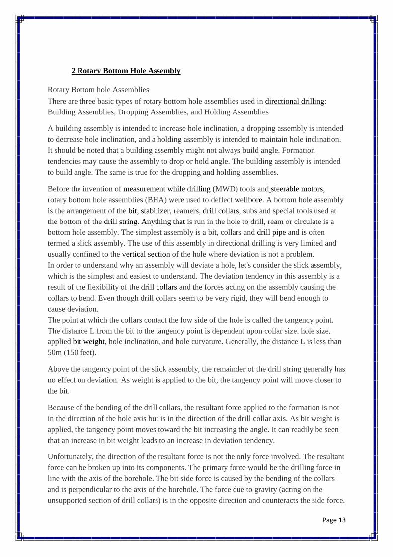
Because of the bending of the drill collars, the resultant force applied to the formation is not
in the direction of the hole axis but is in the direction of the drill collar axis. As bit weight is
applied, the tangency point moves toward the bit increasing the angle. It can readily be seen
that an increase in bit weight leads to an increase in deviation tendency.
Unfortunately, the direction of the resultant force is not the only force involved. The resultant
force can be broken up into its components. The primary force would be the drilling force in
line with the axis of the borehole. The bit side force is caused by the bending of the collars
and is perpendicular to the axis of the borehole. The force due to gravity (acting on the
unsupported section of drill collars) is in the opposite direction and counteracts the side force.
Page 14
The net deviation force is then equal to the summation of the bit side force and the force due
to gravity. If the force due to gravity is greater than the bit side force the angle will drop.
Changing the weight on bit can control the deviation tendency. Increasing the bit weight will
lower the tangency point increasing the angle. Since resultant force is proportional to the sine
of angle, an increase in bit weight increases the bit side force and ultimately the deviation
tendency. Of course, a decrease in bit weight will decrease the deviation tendency.
Effect of Increased Bit Weight
Another factor affecting deviation tendency is the stiffness of the drill collars. Stiffer collars
will bend less, which increases the height to the tangency point. If the tangency point moves
up the hole, then the deviation tendency will be reduced. Therefore, small diameter drill
collars will enhance the deviation tendency.
The addition of a stabilizer above the bit significantly affects the deviation tendency of a
bottom hole assembly. The stabilizer acts as a fulcrum around which the unsupported section
of the bottom hole assembly reacts. The addition of the moment arm between the bit and
stabilizer increases the bit side force. In fact, the single stabilizer assembly is a very strong
building assembly.
3 Steerable motor
A mud motor incorporating a bent housing that may be stabilized like a rotary bottom
hole assembly. A steerable motor can be used to steer the wellbore without drill string
rotation in directional drilling operations, or to drill ahead in a rotary drilling mode.

Page 15
Figure 2.2: Bent points
Methods of Deflection
•Typical steerable motor configuration
B e n t H o u s i n g f o r C h a n g i n g D i r e c t i o nB e n t H o u s i n g f o r C h a n g i n g D i r e c t i o n
W h e n S l i d i n g t h e D r i l l s t r i n gW h e n S l i d i n g t h e D r i l l s t r i n g
S t a b i l i z e r s D e f i n e D i r e c t i o n a l S t a b i l i z e r s D e f i n e D i r e c t i o n a l
T e n d e n c y W h e n R o t a t i n g t h e D r i l l s t r i n gT e n d e n c y W h e n R o t a t i n g t h e D r i l l s t r i n g
Stabilizers Define Directional Tendency
When Rotating the Drillstring
Bent Housing for Changing Direction
When Sliding the Drillstring

Page 16
Figure 2.3: How motor work
• Positive Displacement Motor ‐ PDM
• Fluid flow drives the inner rotor inside the stator
StatorStatic
Rotor Rotating
• The rotor rotation is then transferred to the bit
• When orienting, to build angle The entiredrillstring is not rotating and the bent is orientedtoward the direction of interest
• The amount of angle build in a certain interval iscontrolled through orienting/rotating ratio
Inside the Steerable Motor
41

Page 17
4Rotary steerable assembly
Typically, are deployed when drilling directional, horizontal, or extended-reach wells.
State-of-the-art rotary steerable systems have minimal interaction with the borehole, thereby
preserving borehole quality. The most advanced systems exert consistent side force similar to
traditional stabilizers that rotate with the drill string or orient the bit in the desired direction
while continuously rotating at the same number of rotations per minute as the drill string.
Then, Rotary Steerable System has Revolution Control unit inside it has Battery Power
(Lithium Battery Pack), Navigation Sensors that help to obtain such as the velocity of drilling
and Microprocessor control. Next, as we seen in (Figure 2) Rotary Steerable System works
by apply power from turbine into Collar Rotation and motor that help drill rotating with an
angle. Furthermore, ROTARY MODE steerable motor become "locked" with respect to
trajectory and the hole direction and inclination maintained while drilling.

Page 18
Figure 2.4: Methods of RSS
Methods of Deflection
• Rotary steerable Systems
• Steerable without sliding (100% rotation)
• Can change both inclination and direction downhole

Page 19
Figure 2.5: How RSS work
Geo‐Pilot® Point the Bit Technology
• Rotating Inner Shaft is deflectedin center between bearings withdual eccentric cams
• Results in bit tilt in oppositedirection
• Deflection ( % )
• Toolface direction
73
Page 20
2.2 Previous Work:
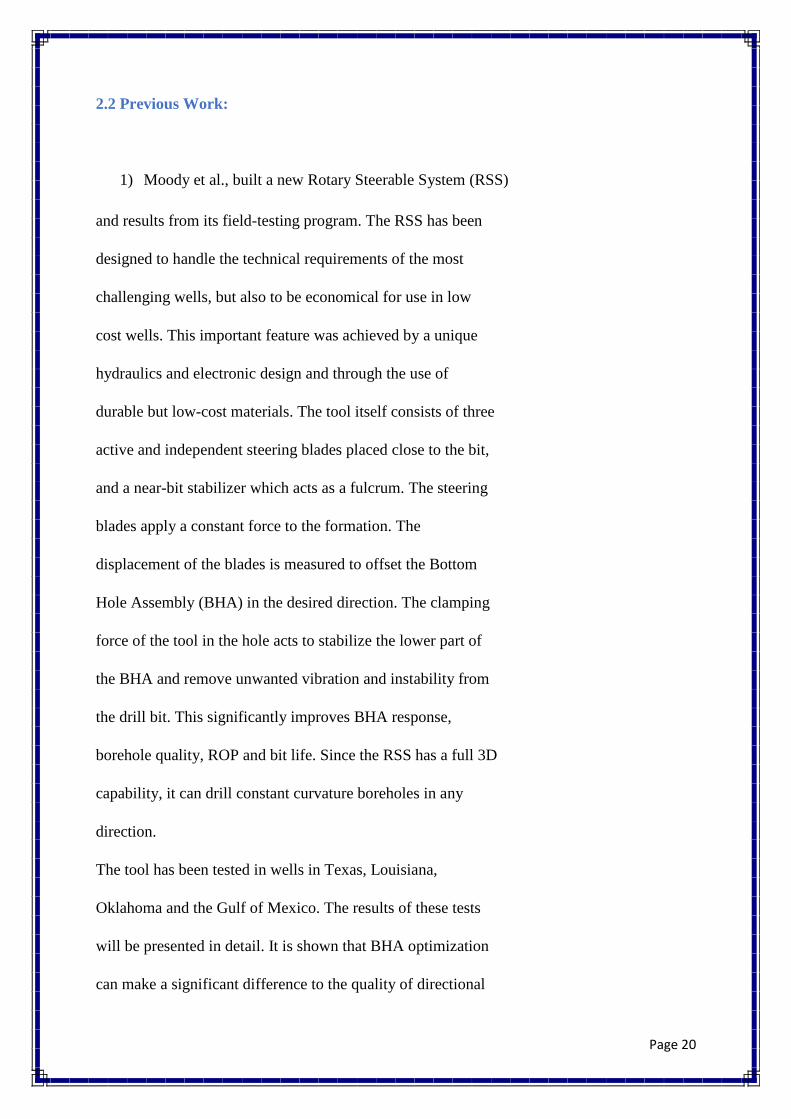
1) Moody et al., built a new Rotary Steerable System (RSS)
and results from its field-testing program. The RSS has been
designed to handle the technical requirements of the most
challenging wells, but also to be economical for use in low
cost wells. This important feature was achieved by a unique
hydraulics and electronic design and through the use of
durable but low-cost materials. The tool itself consists of three
active and independent steering blades placed close to the bit,
and a near-bit stabilizer which acts as a fulcrum. The steering
blades apply a constant force to the formation. The
displacement of the blades is measured to offset the Bottom
Hole Assembly (BHA) in the desired direction. The clamping
force of the tool in the hole acts to stabilize the lower part of
the BHA and remove unwanted vibration and instability from
the drill bit. This significantly improves BHA response,
borehole quality, ROP and bit life. Since the RSS has a full 3D
capability, it can drill constant curvature boreholes in any
direction.
The tool has been tested in wells in Texas, Louisiana,
Oklahoma and the Gulf of Mexico. The results of these tests
will be presented in detail. It is shown that BHA optimization
can make a significant difference to the quality of directional
Page 21
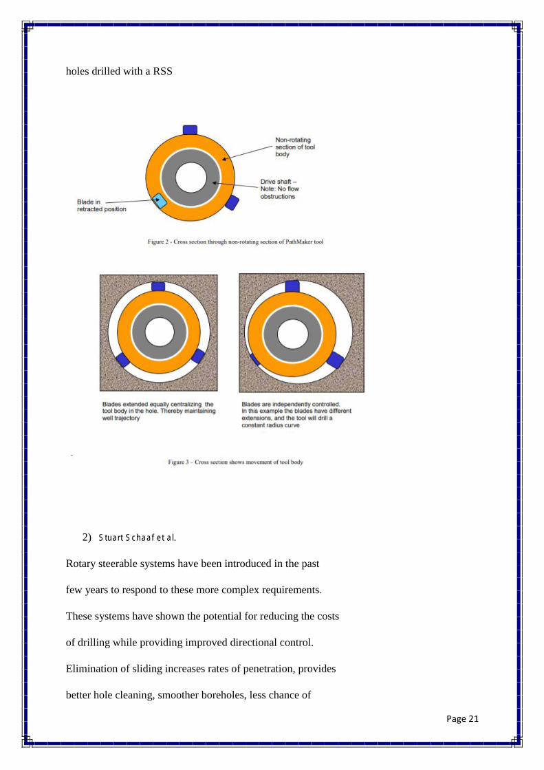
holes drilled with a RSS
2) Stuart Schaaf et al.
Rotary steerable systems have been introduced in the past
few years to respond to these more complex requirements.
These systems have shown the potential for reducing the costs
of drilling while providing improved directional control.
Elimination of sliding increases rates of penetration, provides
better hole cleaning, smoother boreholes, less chance of

Page 22
differential sticking; and the ability to drill further.
Schlumberger has developed a new rotary steerable system,
which functions on a point-the-bit principle. The system has
no non-rotating or stationary parts in contact with the
formation. The system is implemented in a 6 ¾-inch platform
and operates in bore-hole diameters between 8 3/8-inch and 9
7/8-inch.
This paper will present an overview of the new point-the bit
system. Benefits of the system will be discussed. Case
studies from two wells will be presented. The presentation
will discuss the well objectives, the plan implementation, and
include operational highlights and issues. Project results and
improvements in implementation will be presented with
discussion on how the system was utilized to insure value-added
savings.

Page 23
Figure 2.6: Function of Drill Pipe
Figure 2.7: Component of inside Drill Pipe
3) Ali Al Dabyah et al.
To address the client needs, a new generation of RSS has been introduced.
In 2014, a 6¾-in. high-build rate RSS was developed primarily for conventional markets,
which have a
Page 24
need for high build rates and simultaneous acquisition of LWD data. The use of a high-build
rate RSS in
conjunction with an optimized bottom hole assembly (BHA) for build-rate capability has
enabled operators
to achieve build-up rates up to 12°/100 ft.
In 2015, a 4¾-in. high-performance RSS was developed to fill the need of higher weight on
bit and to
provide a simple, rugged design with enhanced reliability.
In this paper the authors present the new generation of rotatory steerable and its impact on the
market.
This paper will be supported by number of case studies from oil and gas.

Page 25
Chapter 3: System Design
3.1 Design Constraints and Design Methodology
3.1.1 Geometrical Constraints
There were few constraints that the project has to find a way around them. One of the
constraints was the size of the drill hole pipe. In our project we simulated the 6.5’’ hole in
real life application by 6.5’’ pipe. In many operation locations around the world, the size of
the hole can be much bigger. That can help a lot regarding the size of the machined parts. The
bigger the size would result in durability in tools life.
3.1.2 Sustainability
Due to the small size that we forced to use; we faced an issue regarding sustainability
of our project. If we able to make the prototype bigger than 6.5’’ in diameter, we could have
used bearings. In Engineering applications bearings offer great help in connected shafts (or
pistons in our project) to a rotating pipe. In this way we can minimize corrosion and wear of
both pistons and drilling pipe.
3.1.3 Environmental
Our prototype has very little impact on the environmental aspect, as it will be
implanted deep inside earth crust. However, we used compressor to force pistons to bend the
drill pipe instead of oil pump. Leakage of oil might be harmful for both environments and the
operators around it. Therefore, using compressed air would be sufficient on both safety and
environmental aspects
3.1.4 Social
Our system can be shared by multi companies. Some companies can use it to drill boreholes
for the customers while others are able to use it to gathering the oil and natural gas to increase
production rate. Thus, the system shall have social impact.
Page 26
3.1.5 Economic
Our prototype is mainly mechanical parts fit together. This means the costs are very
low comparing with installing electronics or electrical components. The maintenance of
mechanical parts can be done with ease and no time waste. This result saving money and time
for companies of oil drilling. Also, our prototype reduces the numbers of maintenance
operators to mechanical engineers, instead of having mechanical, electronics and electrical
engineers to finish maintenance.
3.1.6 Safety
Safety was one of the most concerns in our prototype. We machined every part to the
0.01’’ in most accurate manufacturing machines we had. By having such accuracy, we
managed to lower friction to minimum. By minimizing fumes resulted from frictions between
pistons and drill pipe, we managed to minimize health issues to operator.
3.1.7 Ethical
This project has homogenous previous works. Thus, we took some general ideas from them
and we improved the work by our suggestions to improve the design in terms of safety,
economically, and sustainability.
3.2 Engineering Design Standard:
Engineering standards should be followed in each components of our system. In this section,
we described each component that have been selected for our project. The selected
components are the following; Aluminium Pipe, Drill Bit and O-ring. The Aluminium Pipe
standard has been taken according to Seamless Aluminium Pipe - Series 6061-T6 Schedule
40. The standard of Drill Bit has taken from American Petroleum Institute (API) standard
rock bits. The O-ring was taken from AS-568 Standard O-Rings. See table 3.1

Page 27
Components Engineering Standard Details
Aluminium Pipe Seamless Aluminium Pipe -
Series 6061-T6 Schedule 40
ASME S241MASME
SB241ASTM B241Mil-P-
25995UNS A96061
Drill Bit American Petroleum
Institute (API) standard rock
bits
-0.0 to +1/32 Rock Bit
O-ring As-568 Standard O-
ring
.426 ± .005
Table 3.1: Engineering Standards
3.2.1 Aluminium Pipe:
Length: 39.37 in
Diameter: 3.5 in
3.2.2 Drill Bit:
Diameter: 6.5 in
3.2.3 O-ring:
Inner Diameter: 0.45 in
Outside Diameter: 0.51 in
Thickness: 0.03 in

Page 28
3.3 Theory and Theoretical Calculation
In theory, we can control the directional drilling by controlling the bend of the drill
pipe. By controlling pressure, we can control the bend angle and set it to the desired one.
Maximum Bending calculations
I= π (r。4 - ri
4) / 4
I= π (0.04604
– 0.04392 4) / 4
I= 6.031X10⁻⁷
KN/m2
θ = PL 2
/ 16EI
0.02618 = P*1 2
/ 16*6.031X10-7
*117X106
P = 29.561 KN
Calculation
Fy
= 2F sin (30) +2F sin (60) +F
Forces on each piston -> F=268N
Formula to calculate pressure -> PA=268
P π (ro
2
) =268
Pressure on each set -> Peach set
= 2115.6 kpa
Force on each piston - > Ptotal
=423 kpa
Page 29
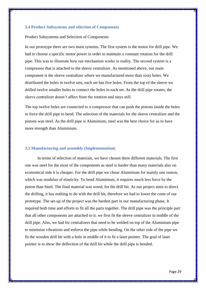
3.4 Product Subsystems and selection of Components
Product Subsystems and Selection of Components
In our prototype there are two main systems. The first system is the motor for drill pipe. We
had to choose a specific motor power in order to maintain a constant rotation for the drill
pipe. This was to illustrate how our mechanism works in reality. The second system is a
compressor that is attached to the sleeve centralizer. As mentioned above, our main
component is the sleeve centralizer where we manufactured more than sixty holes. We
distributed the holes in twelve sets, each set has five holes. From the top of the sleeve we
drilled twelve smaller holes to connect the holes in each set. As the drill pipe rotates, the
sleeve centralizer doesn’t affect from the rotation and stays still.
The top twelve holes are connected to a compressor that can push the pistons inside the holes
to force the drill pipe to bend. The selection of the materials for the sleeve centralizer and the
pistons was steel. As the drill pipe is Aluminium, steel was the best choice for us to have
more strength than Aluminium.
3.5 Manufacturing and assembly (Implementation)
In terms of selection of materials, we have chosen three different materials. The first
one was steel for the most of the components as steel is harder than many materials also on
economical side it is cheaper. For the drill pipe we chose Aluminium for mainly one reason,
which was modulus of elasticity. To bend Aluminium, it requires much less force by the
piston than Steel. The final material was wood, for the drill bit. As our project aims to direct
the drilling, it has nothing to do with the drill bit, therefore we had to lower the costs of our
prototype. The set-up of the project was the hardest part in our manufacturing phase. It
required both time and efforts to fit all the parts together. The drill pipe was the principle part
that all other components are attached to it. we first fit the sleeve centralizer in middle of the
drill pipe. Also, we had for centralizers that need to be welded on top of the Aluminium pipe
to minimize vibrations and enforce the pipe while bending. On the other side of the pipe we
fit the wooden drill bit with a hole in middle of it to fit a laser pointer. The goal of laser
pointer is to show the deflection of the drill bit while the drill pipe is bended.

Page 30
1 Drill Pipe 1 Piece
2 Centralizer 12 pieces
3 Centralizer 2 4 pieces
4 Spacer 2 pieces
5 Piston 60 pieces
6 Drill Bit 1 piece
7 O-ring 60 pieces
8 Sleeve Centralizer 1 piece
Figure 3.1: Exploded assembly of the system
1
2 2 4
5
6
7
8

Page 31
Component Name Picture
Composer
Sleeve Centralizer
Drill Bit
Steel Pipe

Page 32
Aluminium Pipe
Motor
Spacer
Centralizer

Page 33
Small Tube
Dispenser Tool
Table 3.2: Pictures of components

Page 34
Chapter 4: System Testing and Analysis
4.1 Tools:
Figure 4.1: Tape measure
Figure 4.2: Leisner pointer
Figure 4.3: Ruler

Page 35
Figure 4.4: Board
4.2 Calculation:
4.2.1 Calculation several Materials:
I= π (r。4 - ri
4) / 4
θ = PL 2
/ 16EI
ymax = PL
3 / 48EI
Material Force (KN) ymax (mm)
Copper 29.561 0.872
Aluminum 28.9 5.313
PVC 1.96 8.69
4.2.2 Calculation Pressure:
D= 0.5 in =1.25 cm=0.0125 m
Fy= 2F sin (30) +2F sin (60) +F
Fy= F (2sin (30) +2sin (60) +1)

Page 36
=3.737F
1000=3.732F
F= 1000/3.732
F=268N
PA=268
P π (ro2)
=268
P=268/ π *r2
P=268/ π *(0.0635)2
Peach set = 2115.6 kpa
Ptotal=423 kpa
Figure 4.5: Force in different direction with same angle acting a point
4.3 Procedure:
1. We fixed the laser pointer to the middle of the drill bit and point it to the
board.

Page 37
2. We connected the top holes of the sleeve together and then connect them to
the compressor.
3. Then we set the compressor to the calculated pressure that is needed to bend
the Aluminium pipe.
4. Record the deflection of the laser pointer on the board.
5. Apply Pythagoras theorem to record the angle of the bend.
( )
4.4 Results
Angle of Deflection Force (KN)
0.5◦ 65.688
0.7◦ 91.96
0.9◦ 118.238
1.1◦ 144.5136
1.3◦ 170.788
Table 4.1: Calculation Force
Figure 4.6: Graph of Force Vs Angle
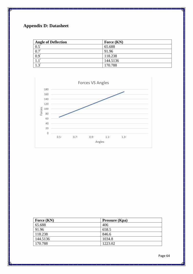
We notice on graph between force and deflection of angle is direct relation if we
want to increase the deflection of angle, we need to increase the amount of force.
0
20
40
60
80
100
120
140
160
180
0.5◦ 0.7◦ 0.9◦ 1.1◦ 1.3◦
Forc
es
Angles
Forces VS Angles

Page 38
PA=F
Force (KN) Pressure (Kpa)
65.688 406
91.96 658.5
118.238 846.6
144.5136 1034.8
170.788 1223.02
Table 4.2: Calculation Pressure
Figure 4.7: Graph of Force Vs Pressure
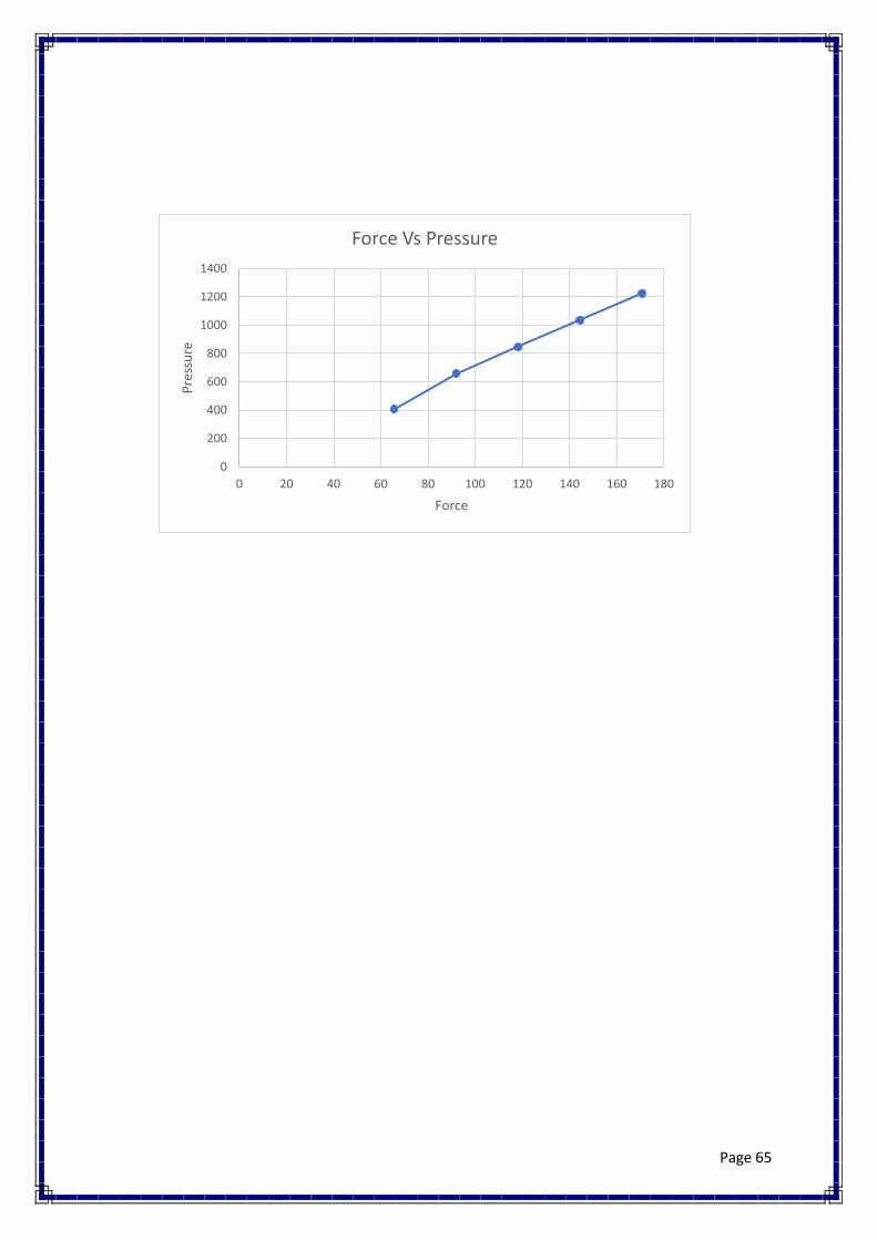
Also, we realize between the force and pressure is direct relation, if we want to bend the drill
pipe, we need high pressure to push the pistons with high amount of force.
0
200
400
600
800
1000
1200
1400
0 20 40 60 80 100 120 140 160 180
Pre
ssu
re
Force
Force Vs Pressure

Page 39
Chapter 5: Project Management
5.1 Project Plan
In our project, there are many tasks included. Each task is assigned to one or more members.
Here is the all information about the tasks, team members, and the duration of each task to be
completed. See table 5.1 for tasks & durations and table 5.2 for the assigned members.
Task 1 Start Date Days to complete Identifying the project
6/01/2019
16
Determine the
objectives Subdividing small tasks
to collect information Search and review the
previous work Writing chapter 1 of
the report Preparing and submit
the forms Write chapter 2
Task 2 Brain storming and
gathering ideas for the
conceptual design
20/01/2019
10 Draw the first
conceptual design Selected the
appropriate Materials Searching for the parts Order the parts what
we want on global sites
30/01/2019
3
Buying the available
part from local shop 2
Task 3 Solid works Design
1/02/2019
12 Calculation of hole
diameter Calculation pipe
diameter Type of material of
drilling pipe Power of motor 5/02/2019 6 Write chapter 3 6/02/2019 3
Task 4 Initial prototype 10/02/2019 10
Preparing the Mid-term
presentation
14/02/2019
2
Writing chapter 4 8

Page 40
Task 5
Start assembly the project
3/03/2019
15 Testing the system Finding the errors and
upgrade the system Task 6
Finishing the final
report 06/04/2019
6 Finalized the project
Final presentation 11/04/2019
Table 5.1: Tasks and their durations
Task 1 Responsible Identifying the project
All Team
Determine the objectives
Subdividing small tasks to collect information
Search and review the previous work
Writing chapter 1 of the report
Preparing and submit the forms
Write chapter 2
Task 2 Brain storming and gathering ideas for the
conceptual design
All Team
Draw the first conceptual design Metab Selected the appropriate Materials
Nayef Searching for the parts
Order the parts what we want on global sites
Buying the available part from local shop
Task 3 Solid works Design Nayef + Metab
Calculation of hole diameter Fayed + Nawaf Calculation pipe diameter Metab + Nayef
Type of material of drilling pipe All Team Power of motor Nawaf + Fayed Write chapter 3 Nayef + Fayed
Task 4 Initial prototype
Fayed + Nawaf Preparing the Mid-term presentation
Writing chapter 4
Task 5
Start assembly the project
Nawaf+Nayef Testing the system
Finding the errors and upgrade the system
Task 6 Finishing the final report Metab+Nayef
Finalized the project Fayed + Nawaf Final presentation
Table 5.2: Tasks and assigned members

Page 41
5.2: Contribution of Team Members
The tasks in this project was assigned to one member or more members. It depends to the
ability of doing the task and the time required to complete the task. Table 5.3 shows the tasks
and the members with how many percentages of contributing for each member.
Task 1 Responsible Percent Complete
Identifying the project
All Team
100%
Determine the objectives
Subdividing small tasks to collect
information
Search and review the previous
work
Writing chapter 1 of the report
Preparing and submit the forms
Write chapter 2
Task 2
Brain storming and gathering ideas
for the conceptual design
All Team 100%
Draw the first conceptual design Metab 100%
Selected the appropriate Materials
Nayef
100% Searching for the parts
Order the parts what we want on
global sites
Buying the available part from local
shop
Task 3
Solid works Design Nayef + Metab 100%
Calculation of hole diameter Fayed + Nawaf 100%
Calculation pipe diameter Metab + Nayef 100%
Type of material of drilling pipe All Team 100%
Power of motor Nawaf + Fayed 30%
Write chapter 3 Nayef + Fayed 100%
Task 4
Initial prototype
Fayed + Nawaf 60%
Preparing the Mid-term
presentation
100%
Writing chapter 4
Task 5
Start assembly the project
Nawaf+Nayef
30% Testing the system
Finding the errors and upgrade the
system
Task 6
Finishing the final report Metab+Nayef 10%
Finalized the project Fayed + Nawaf Final presentation
Table 5.3: Tasks the contribution of the members

Page 42
5.3: Project Execution Monitoring
During our project, we had many activities which relates to improve our project. These
activities including the important meeting and events that related to our senior project. In
table 5.4 shows the list of meeting and other events for our project during spring semester
2019.
Time / Date Activities / Events
Three times a week Assessment Class
Weekly Meeting with group members
Biweekly Meeting with advisor
14 March 2019 Finish first prototype
21 March 2019 Midterm presentation
14 April 2019 Finishing final prototype
16 April 2019 Test the system
18 April 2019 Final submission of report
2 April 2019 Final presentation
Table 5.4: Dates of the activates and events
5.4: Challenges and Decision Making:
During the project phases, we faced some challenges that effect the progress of the project.
Following challenges are the main challenges we have faced:
1) Finding the Materials
2) Dimensions of Components
3) Manufacture complex component
5.4.1: Finding the Materials:
In our Project, we faced an issue for choosing a material such as Aluminium, Copper and
PVC. Furthermore, we did calculation for three materials depending on the standards then we
chose which material is applicable in our project in order to bend the pipe without broken.
5.4.2: Dimensions of components:
Some diminution part is not available in market, so we had to manufacture it, such as we
manufacture aluminium pip and steel pipe in casting with rolling operation. Also, we
manufacture the drill bit in order to fit inside a hole by using a shaft and cutting edges.

Page 43
5.4.3: Manufacture complex component:
In our project we had a problem that we cannot manufacture complex part in any workshop,
so we looking for a workshop that they have CNC machine in order to manufacture
centralizer which is the reacquired part. Even we find a workshop with CNC machine, they
can’t do finishing in the part, so the piston will not fit.
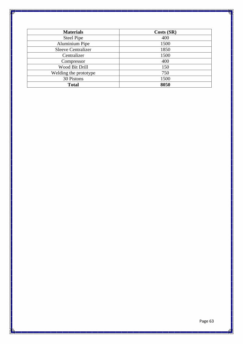
5.5: Project Bill of Materials and Budget
Table 5.5 shows the materials that we purchased and their costs in Saudi Riyals (SR). This
table includes also the manufacturing and failed part costs.
Materials Costs (SR)
Steel Pipe 400
Aluminium Pipe 1500
Sleeve Centralizer 1850
Centralizer 1500
Compressor 400
Wood Bit Drill 150
Welding the prototype 750
30 Pistons 1500
Total 8050
Table 5.5: Bill of Materials

Page 44
Chapter 6: Project Analysis
6.1: Life-long Learning
When we are working in our project, we have learned and gain some knowledge about the
important skills which was required to complete our project. By working as a team, we
succeed to improve our skills in time management, communicate in effective way with
members of the group. In this part, we will discuss the skills and experiences which we have
learned since we worked in our project.
6.1.1: Software Skills
In this project, we have learned various skills and experiences from some software, such as
Solid works and Microsoft Word. These two programs are familiar for us because we have
used them during university life. We used some advanced skills in these programs which we
have not use it before. For instance, we used our Solid works skills to design our system part
by part then, we used mate tools to assemble the parts together.
6.1.2: Hardware Skills:
During our project, we used some new devices that aim us to collect the data. we used two
types of measurements. First was measurement tape which able to measure the distance
between laser pointer and the board. We learned how to apply mathematical equations such
as Pythagoras theorem to calculate deflect angle.
6.1.3: Time Management Skills
By our project life, we gain one of the important skills which is the time management. While
we want to reach to our purpose, we have to manage the time to fit with the tasks. We divided
the tasks into specific deadline to be finished on or before the deadline. One of the tools that
we used to manage our time is Gantt Chart. We divide our tasks and subtasks into start and
end dates. Also, we kept updating the Gantt Chart with our advisors to keep them in touch
about what we have done weekly.

Page 45
6.1.4: Project Management
In our project, we divided the works between members of the group. Each one of the
members has his own work which should be done individually. Then, we had a meeting two
times a week to discuss and collect the work that have done by that member. Mostly, our
group has divided to two teams. The first team was focusing on the research and report.
While, the other team was focusing on the prototype and manufacturing.
6.2 Impact of Engineering Solutions
Our project has various impacts in terms of society, economy, and environment. In this
section, there are all the impacts of our project in terms of what previously mentioned.
6.2.1: Society
Our project is an advantage in terms of society. Installing private water supplies and drilling
boreholes for our customers often involves the installation of underground pipework to
deliver water from the source to the area of its intended use.
6.2.2: Economy
Our project assists the people in terms of economy. Directional Drilling will merge into the
ever-growing inventory of technologies that create the economic that extend the lives of, and
yield more reverse from oil and gas fields yielding more production than early estimate even
as it remains impossible to count which particular new technology gave rise to so much more
production. This project was expected to cost approximately more than 9000 SR. After we
finished the final project, we found that it costs around 8000 SR.
6.2.3: Environmentally
Our project helps the society in directional drilling can be further enhanced by taking the
right safety precautions. Workers who are supplied with the right safety equipment and
trained in the correct operation of all horizontal directional drilling equipment are able to
work both efficiently and, in a manner, that most limits the impact of their activities on the
environment.

Page 46
6.3 Contemporary Issues Addressed:
In our prototype there was huge friction fumes coming from pitons forcing drill pipe to bend.
Those fumes are harmful to humans for many reasons. The first issue is the bad effects of air
pollution on human body. There are many organs and bodily functions that can be harmed,
the consequences including: respiratory diseases,
cardiovascular damage, headaches and anxiety, Irritation of the eyes, nose and throat and
nervous system damage.

Page 47
Chapter 7: Conclusion and Future Recommendation
7.1 Conclusion:
In every project, people learn many things that assist them in the normal life. From this
project, we gained the experiences, we improved our communication skills, and we learned
new things. Also, we achieved important results from this project that will encourage us in
terms of working in different projects in future. In engineering science, our project is
consisting various areas of engineering including; Mechanical Design, solid mechanics, and
thermodynamics which help us to improve our background on these areas. In this project, we
learned how to use various manufacturing processes that are essential in our lives such as
finishing. Moreover, we improved our skills regarding to engineering software such as
solidworks. This project as any other project has some challenges. We faced a problem
regrading to finding the workshops that have CNC machining.
7.2 Future Recommendation:
There will be great deal of friction between the pistons and the drill pipe, hence it reduces the
life of both parts. Our recommendation is to use special type of lubricants or bearings. Also,
some developments can be made by using pressurized fluids to turn the drill pipe instead of
regular motor. By having pressurized fluids, the forces can be used in many areas such as to
use jetting techniques for directional drilling. Moreover, pressurized fluids can work as a
motor by installing turbines inside the bottom hole assembly. Those turbines can either
generate electricity to rotate the drill pipe, or/and to helps to record vital data and send it to
the operator on the surface.

Page 48
8. References:
[online] Available at: Glossary.
https://www.glossary.oilfield.slb.com/en/Terms/r/rotary_steerable_system.aspx
[online] Available at: https://www.glossary.oilfield.slb.com/en/Terms/s/steerable_motor.aspx
En.wikipedia.org. (2019). Drilling rig. [online] Available at: https://en.wikipedia.org/wiki/Drilling_rig#Drilling_rig_classification [Accessed 17 Feb. 2019].
Hibbeler, R., & Yap, K. Mechanics of materials.
Ward-Smith, J. (2012). Mechanics of Fluids, Ninth Edition. Boca Raton: CRC Press.
Drilling Formulas and Drilling Calculations. (2019). Deviating the Wellbore by Jetting and Whipstock
(Directional Drilling). [online] Available at: http://www.drillingformulas.com/deviating-the-wellbore-
by-jetting-and-whipstock-directional-drilling/
Anon, (2019). [online] Available at: https://www.netwasgroup.us/services-2/rotary-bottomhole-
assemblies
Bybee, K. (2010). Design, Development, and Testing of a Slimhole Rotary-Steerable System. Journal
of Petroleum Technology, 62(12), pp.81-83.
SCHAAF, STUART, Schlumberger Oilfie (2000). Application of a Point the Bit Rotary Steerable
System in Directional Drilling Prototype Well Bore Profiles for Aera Energy, LLC. AAPG Bulletin, 84.
Wilson, A. (2016). New Rotary-Steerable System Delivers High Dogleg Severity, Improves
Penetration Rate. Journal of Petroleum Technology, 68(12), pp.60-61
Li, S. (2013). Construction Monitoring of a Municipal Gas Pipeline during Horizontal Directional
Drilling. Journal of Pipeline Systems Engineering and Practice, 4(4), p.04013005.
Jaganathan, A., Shah, J., Allouche, E., Kieba, M. and Ziolkowski, C. (2011). Modeling of an obstacle
detection sensor for horizontal directional drilling (HDD) operations. Automation in Construction,
20(8), pp.1079-1086

Page 49
Inyang, I. and Whidborne, J. (2019). Bilinear modelling, control and stability of directional
drilling. Control Engineering Practice, 82, pp.161-172
Muchendu, P., J.G, D. and Njeri, E. (2014). Determination of optimum drilling parameters using 8.5-
inch tricone bits in olkaria geothermal steamfield, Kenya. IOSR Journal of Applied Geology and
Geophysics, 2(2), pp.11-28.
Fei, Y., Cong, S. and Bian, B. (2011). Hydraulic System Simulation of Heavy Horizontal Directional
Drilling Head. Advanced Materials Research, 287-290, pp.428-431.
Page 50
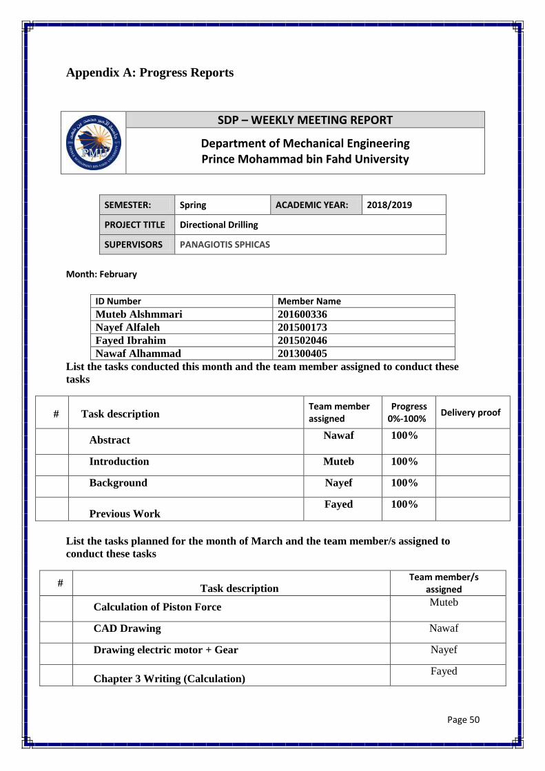
Appendix A: Progress Reports
SDP – WEEKLY MEETING REPORT
Department of Mechanical Engineering Prince Mohammad bin Fahd University
SEMESTER: Spring ACADEMIC YEAR: 2018/2019
PROJECT TITLE Directional Drilling
SUPERVISORS PANAGIOTIS SPHICAS
Month: February
ID Number Member Name
Muteb Alshmmari 201600336
Nayef Alfaleh 201500173
Fayed Ibrahim 201502046
Nawaf Alhammad 201300405
List the tasks conducted this month and the team member assigned to conduct these
tasks
# Task description Team member assigned
Progress 0%-100%
Delivery proof
Abstract Nawaf 100%
Introduction Muteb 100%
Background Nayef 100%
Previous Work
Fayed 100%
List the tasks planned for the month of March and the team member/s assigned to
conduct these tasks
# Task description
Team member/s assigned
Calculation of Piston Force Muteb
CAD Drawing Nawaf
Drawing electric motor + Gear Nayef
Chapter 3 Writing (Calculation)
Fayed
Page 51
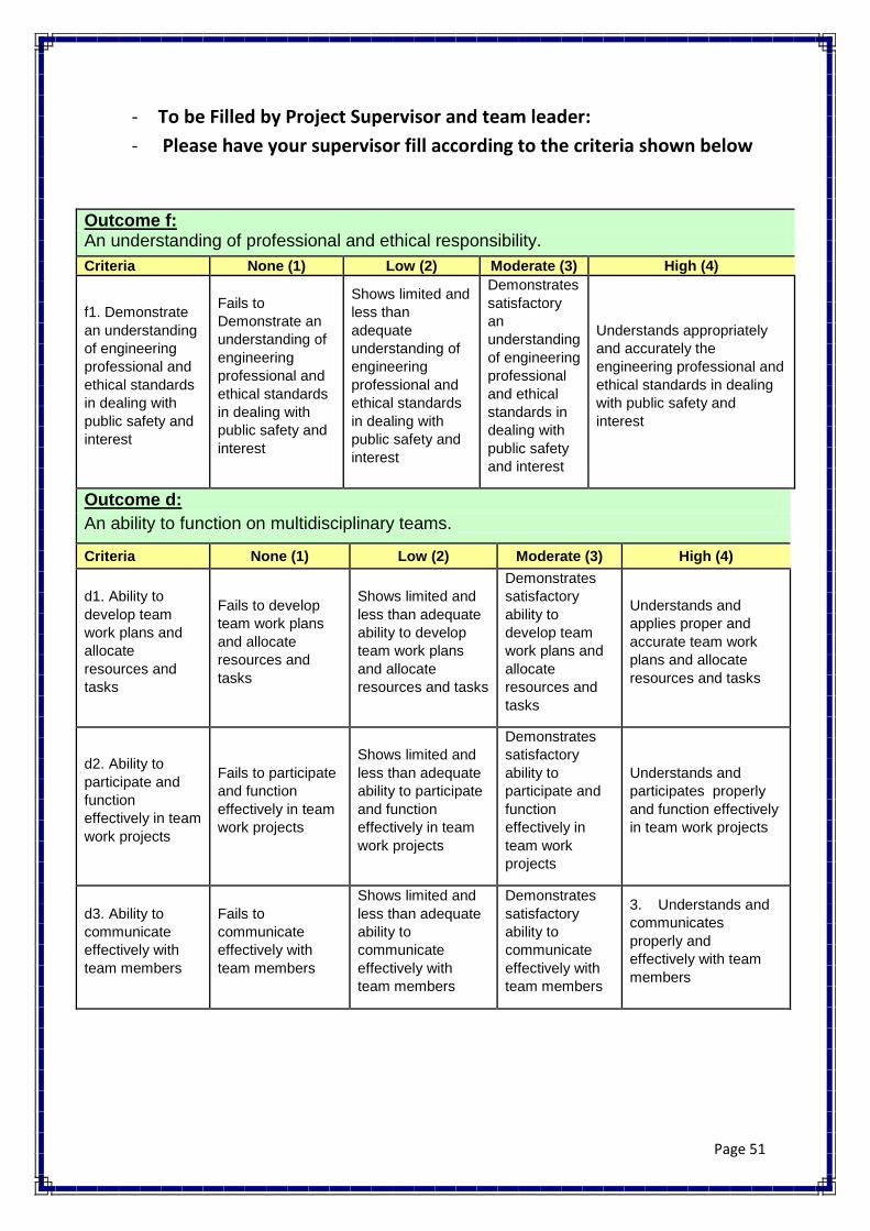
- To be Filled by Project Supervisor and team leader:
- Please have your supervisor fill according to the criteria shown below
Outcome f: An understanding of professional and ethical responsibility.
Criteria None (1) Low (2) Moderate (3) High (4)
f1. Demonstrate
an understanding
of engineering
professional and
ethical standards
in dealing with
public safety and
interest
Fails to
Demonstrate an
understanding of
engineering
professional and
ethical standards
in dealing with
public safety and
interest
Shows limited and
less than
adequate
understanding of
engineering
professional and
ethical standards
in dealing with
public safety and
interest
Demonstrates
satisfactory
an
understanding
of engineering
professional
and ethical
standards in
dealing with
public safety
and interest
Understands appropriately
and accurately the
engineering professional and
ethical standards in dealing
with public safety and
interest
Outcome d:
An ability to function on multidisciplinary teams.
Criteria None (1) Low (2) Moderate (3) High (4)
d1. Ability to
develop team
work plans and
allocate
resources and
tasks
Fails to develop
team work plans
and allocate
resources and
tasks
Shows limited and
less than adequate
ability to develop
team work plans
and allocate
resources and tasks
Demonstrates
satisfactory
ability to
develop team
work plans and
allocate
resources and
tasks
Understands and
applies proper and
accurate team work
plans and allocate
resources and tasks
d2. Ability to
participate and
function
effectively in team
work projects
Fails to participate
and function
effectively in team
work projects
Shows limited and
less than adequate
ability to participate
and function
effectively in team
work projects
Demonstrates
satisfactory
ability to
participate and
function
effectively in
team work
projects
Understands and
participates properly
and function effectively
in team work projects
d3. Ability to
communicate
effectively with
team members
Fails to
communicate
effectively with
team members
Shows limited and
less than adequate
ability to
communicate
effectively with
team members
Demonstrates
satisfactory
ability to
communicate
effectively with
team members
3. Understands and
communicates
properly and
effectively with team
members

Page 52
Indicate the extent to which you agree with the above statement, using a scale of 1-4
(1=None; 2=Low; 3=Moderate; 4=High)
# Name Criteria (d1) Criteria (d2) Criteria (d3) Criteria (f1)
1 Muteb Alshmmari 3 3
3 3
2 Nayef Alfaleh 3 3
3 3
3 Fayed Ibrahim 3 3
3 3
4 Nawaf Alhammad 3 3
3 3

Page 53
SDP – WEEKLY MEETING REPORT
Department of Mechanical Engineering Prince Mohammad bin Fahd University
SEMESTER: Spring ACADEMIC YEAR: 2018/2019
PROJECT TITLE Directional Drilling
SUPERVISORS PANAGIOTIS SPHICAS
Month: February
Member Name ID Number
Muteb Alshmmari 201600336
Nayef Alfaleh 201500173
Fayed Ibrahim 201502046
Nawaf Alhammad 201300405
List the tasks conducted this month and the team member assigned to conduct these
tasks
# Task description Team member assigned
Progress 0%-100%
Delivery proof
Solid work Designing Nawaf 100%
Calculation of piston force Muteb 100%
Design Gears (First Approach) Nayef 100%
Writing Chapter 3 (Calculation)
Fayed 100%
List the tasks planned for the month of April and the team member/s assigned to
conduct these tasks
# Task description
Team member/s assigned
Testing the Prototype Muteb
Prepare Component from Workshop Nawaf + Nayef
Prepare Final Presentation Fayed

Page 54
- To be Filled by Project Supervisor and team leader:
- Please have your supervisor fill according to the criteria shown below
Outcome f: An understanding of professional and ethical responsibility.
Criteria None (1) Low (2) Moderate (3) High (4)
f1. Demonstrate
an understanding
of engineering
professional and
ethical standards
in dealing with
public safety and
interest
Fails to
Demonstrate an
understanding of
engineering
professional and
ethical standards
in dealing with
public safety and
interest
Shows limited and
less than
adequate
understanding of
engineering
professional and
ethical standards
in dealing with
public safety and
interest
Demonstrates
satisfactory
an
understanding
of engineering
professional
and ethical
standards in
dealing with
public safety
and interest
Understands appropriately
and accurately the
engineering professional and
ethical standards in dealing
with public safety and
interest
Outcome d:
An ability to function on multidisciplinary teams.
Criteria None (1) Low (2) Moderate (3) High (4)
d1. Ability to
develop team
work plans and
allocate
resources and
tasks
Fails to develop
team work plans
and allocate
resources and
tasks
Shows limited and
less than adequate
ability to develop
team work plans
and allocate
resources and tasks
Demonstrates
satisfactory
ability to
develop team
work plans and
allocate
resources and
tasks
Understands and
applies proper and
accurate team work
plans and allocate
resources and tasks
d2. Ability to
participate and
function
effectively in team
work projects
Fails to participate
and function
effectively in team
work projects
Shows limited and
less than adequate
ability to participate
and function
effectively in team
work projects
Demonstrates
satisfactory
ability to
participate and
function
effectively in
team work
projects
Understands and
participates properly
and function effectively
in team work projects
d3. Ability to
communicate
effectively with
team members
Fails to
communicate
effectively with
team members
Shows limited and
less than adequate
ability to
communicate
effectively with
team members
Demonstrates
satisfactory
ability to
communicate
effectively with
team members
3. Understands and
communicates
properly and
effectively with team
members

Page 55
Indicate the extent to which you agree with the above statement, using a scale of 1-4
(1=None; 2=Low; 3=Moderate; 4=High)
# Name Criteria (d1) Criteria (d2) Criteria (d3) Criteria (f1)
1 Muteb Alshmmari 4 4
4 4
2 Nayef Alfaleh 4 4
4 4
3 Fayed Ibrahim 4 4
4 4
4 Nawaf Alhammad 4 4
4 4

Page 56
Appendix B: Engineering standards (Local and International)
Components Engineering Standard Details
Aluminium Pipe Seamless Aluminium Pipe -
Series 6061-T6 Schedule 40
ASME S241MASME
SB241ASTM B241Mil-P-
25995UNS A96061
Drill Bit American Petroleum
Institute (API) standard rock
bits
-0.0 to +1/32 Rock Bit
O-ring As-568 Standard
O’ring
.426 ± .005

Page 57
Appendix C: CAD drawing and Bill of Materials
1 Drill Pipe 1 Piece
2 Centralizer 12 pieces
3 Centralizer 2 4 pieces
4 Spacer 2 pieces
5 Piston 60 pieces
6 Drill Bit 1 piece
7 O-ring 60 pieces
8 Sleeve Centralizer 1 piece
1
2 2 4
5
6
7
8

Page 58

Page 59

Page 60

Page 61

Page 62
Page 63
Materials Costs (SR)
Steel Pipe 400
Aluminium Pipe 1500
Sleeve Centralizer 1850
Centralizer 1500
Compressor 400
Wood Bit Drill 150
Welding the prototype 750
30 Pistons 1500
Total 8050
Page 64
Appendix D: Datasheet
Angle of Deflection Force (KN)
0.5◦ 65.688
0.7◦ 91.96
0.9◦ 118.238
1.1◦ 144.5136
1.3◦ 170.788
Force (KN) Pressure (Kpa)
65.688 406
91.96 658.5
118.238 846.6
144.5136 1034.8
170.788 1223.02
0
20
40
60
80
100
120
140
160
180
0.5◦ 0.7◦ 0.9◦ 1.1◦ 1.3◦
Forc
es
Angles
Forces VS Angles
Page 65
0
200
400
600
800
1000
1200
1400
0 20 40 60 80 100 120 140 160 180
Pre
ssu
re
Force
Force Vs Pressure

Page 66
Appendix E: Operation Manual
To run the prototype, please follow these procedures:
1. We fixed the laser pointer to the middle of the drill bit and point it to the
board.
2. We connected the top holes of the sleeve together and then connect them to
the compressor.
3. Then we set the compressor to the calculated pressure that is needed to bend
the Aluminium pipe.
4. Record the deflection of the laser pointer on the board.
5. Apply Pythagoras theorem to record the angle of the bend

Page 67
Appendix F: Gantt Chart
Task 1 Start Date Days to complete Identifying the project
6/01/2019
16
Determine the
objectives Subdividing small tasks
to collect information Search and review the
previous work Writing chapter 1 of
the report Preparing and submit
the forms Write chapter 2
Task 2 Brain storming and
gathering ideas for the
conceptual design
20/01/2019
10 Draw the first
conceptual design Selected the
appropriate Materials Searching for the parts Order the parts what
we want on global sites
30/01/2019
3
Buying the available
part from local shop 2
Task 3 Solid works Design
1/02/2019
12 Calculation of hole
diameter Calculation pipe
diameter Type of material of
drilling pipe Power of motor 5/02/2019 6 Write chapter 3 6/02/2019 3
Task 4 Initial prototype 10/02/2019 10
Preparing the Mid-term
presentation
14/02/2019
2
Writing chapter 4 8 Task 5
Start assembly the project
3/03/2019
15 Testing the system

Page 68
Finding the errors and
upgrade the system Task 6
Finishing the final
report 06/04/2019
6 Finalized the project
Final presentation 11/04/2019