design and manufacture of a high-g unmanned aerial vehicle ... · design and manufacture of a...
TRANSCRIPT
Design and Manufacture of a High-g Unmanned Aerial Vehicle Structure
TECHNOLOGY LABORATORY FOR ADVANCED COMPOSITESDepartment of Aeronautics and Astronautics
Massachusetts Institute of Technology
Seth S. KesslerAdvisor: Prof. S. Mark Spearing
Draper Advisor: Greg Kirkos
TELAC-11/17/99 2
WIDE AREA SURVEILLANCE PROJECTILE
• WASP commenced in 1997
• Developed at Charles Stark Draper Laboratories
• Small autonomous flyer launched in an artillery shell,
deployed over the battlefield
• Reduce the risk and time of obtaining crucial
battlefield reconnaissance data
• Expendable vehicle, low manufacturing costs

TELAC-11/17/99 3
PHASE I — INITIAL PROOF OF CONCEPT
• Meet geometric constraints of 5” naval shell
• Design vehicle components to survive 15,000 g’s
• Largely Al design for fabrication & cost considerations– could not maintain flight because of weight– difficult to control because of cg location
Tail Section
Flyer
Projectile

TELAC-11/17/99 4
PHASE II — INTEGRATED VEHICLE DEMONSTRATION
• 155 mm shell launched at 16,000 g’s
• Reducing weight for endurance and control– introduction of composite to key components– exploration of manufacturing options
• Functional test article demonstration with components
155 mm SHELL LAUNCH
Protective Shroud Design and Analysis
TELAC-11/17/99 6
PROTECTIVE SHROUDShroud attachmentring
Gap
Gap
• Supports vehicle during gun launch– Provides load path for acceleration force– Most of vehicle in tension, prevents buckling– Relieves tail section requirements, improves cg
• Bears 60,000 lbs force of expulsion charge
• Protects vehicle during balloting
• Provide ballistic weight for trajectory tables
TELAC-11/17/99 7
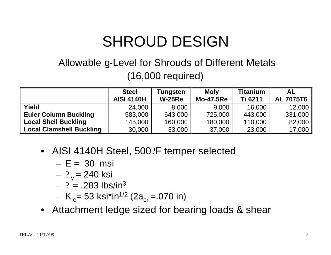
SHROUD DESIGN
Steel Tungsten Moly Titanium ALAISI 4140H W-25Re Mo-47.5Re Ti 6211 AL 7075T6
Yield 24,000 8,000 9,000 16,000 12,000Euler Column Buckling 583,000 643,000 725,000 443,000 331,000Local Shell Buckling 145,000 160,000 180,000 110,000 82,000Local Clamshell Buckling 30,000 33,000 37,000 23,000 17,000
• AISI 4140H Steel, 500?F temper selected– E = 30 msi– ? y = 240 ksi– ? = .283 lbs/in3
– KIc= 53 ksi*in1/2 (2acr =.070 in)
• Attachment ledge sized for bearing loads & shear
Allowable g-Level for Shrouds of Different Metals(16,000 required)
TELAC-11/17/99 8
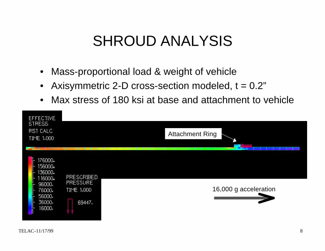
SHROUD ANALYSIS
• Mass-proportional load & weight of vehicle• Axisymmetric 2-D cross-section modeled, t = 0.2”• Max stress of 180 ksi at base and attachment to vehicle
Attachment Ring
16,000 g acceleration

INTRODUCTION OF COMPOSITE TO KEY COMPONENTS
Composite Cylinder Design, Analysis and Testing

TELAC-11/17/99 10
TAIL SECTION DESIGN OBJECTIVES
• Minimal configuration change
• Weight savings over previous design
• Be able to model and analyze structure
• Understanding of manufacturing concerns
• Size section by prescribed launch loads

TELAC-11/17/99 11
ORIGINAL MASS SAVINGS STUDY
• Mass savings over original design
• Illustrates the advantages of composite sections to Al
• Significant displacement of cg for control stability
Material Comment Tail Overall7075 Al Original - -7075 Al Optimized 39% 10%As4 Gr/Ep 20 Ply 92% 23%As4 Gr/Ep 40 Ply 85% 21%
More detailed analysis needed on composite
TELAC-11/17/99 12
CYLINDER DESIGN APPROACH• Static model to predict fracture
– modeled in I-DEAS, processed in ABAQUS– maximum stress components identified in ABAQUS Post – CLPT solver on MATLAB w/Tsai-Wu failure criteria
• Dynamic model to predict buckling– modeled in I-DEAS, processed in ABAQUS– sensitivity trade study to save time in future configurations
• Tests to validate model– compression tests on MTS machine– air-gun tests at Picatinny Arsenal

TELAC-11/17/99 13
REPRESENTATIVE CONFIGURATION
3.5”
120?
1/8” short slot
1/4” long slot
fixed
2”
5.5”5”
12 lbs @ 12,000 g’s
SIDE VIEW BOTTOM VIEW

TELAC-11/17/99 14
FAILURE PREDICTION METHOD
• Elements of max stress identified in ABAQUS Post
• Axial, circumferential, and shear stress recorded
• Laminate Tsai-Wu failure constants calculated in Matlab
• Equation solver used to find failure load– stress scales linearly with load before buckling– FEA solution in ABAQUS with 1000 lbs load– solve Tsai-Wu equality using stress*X scaling factor
TELAC-11/17/99 15
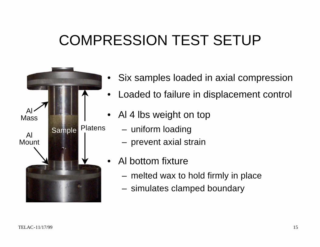
COMPRESSION TEST SETUP
• Six samples loaded in axial compression
• Loaded to failure in displacement control
• Al 4 lbs weight on top– uniform loading– prevent axial strain
• Al bottom fixture– melted wax to hold firmly in place – simulates clamped boundary
Sample
Al Mass
PlatensAl
Mount

TELAC-11/17/99 16
MANUFACTURING
• Curing– AS4/3501-6 carbon fiber composite– hand layed-up on 3.5” diameter mandrel– 3 tubes of [0/±45]3s standard cure and postcure
• Machining– Carbide band-saw used to cut to 5.5” long– Slots milled with two passes of carbide endmill– Half samples with long slots, half short slots

TELAC-11/17/99 17
COMPRESSION TEST RESULTS
• Long slots– ? u?45,000 lbs (range of 44,000 - 45,200 lbs)– failure caused by buckling near slot
Load Displacement Graph
-50000
-45000
-40000
-35000
-30000
-25000
-20000
-15000
-10000
-5000
01.711.721.731.741.751.761.771.78
displacement (in)
com
pre
ssiv
e lo
ad (
lbs) First ply failure

TELAC-11/17/99 18
COMPARISON OF FEM AND TESTS
• Predicted buckling load of 56,400 lbs• Predicted fracture strength of 64,100 lbs
First Buckling Mode
45,000 lbs
Tested Sample

TELAC-11/17/99 19
• Short slots– ? u?56,000 lbs (range of 55,000 - 61,000)– failure caused at 45? plies
COMPRESSION TEST RESULTS
Load Displacement Graph-60000
-55000
-50000
-45000
-40000
-35000
-30000
-25000
-20000
-15000
-10000
-5000
01.721.731.741.751.761.771.781.791.8
displacement (in)
com
pre
ssiv
e lo
ad (
lbs) First ply failure

TELAC-11/17/99 20
COMPARISON OF FEM AND TESTS
• Predicted Buckling load of 92,700 lbs• Predicted Fracture strength of 51,900 lbs
First Buckling Mode
56,000 lbs
Tested Sample
TELAC-11/17/99 21
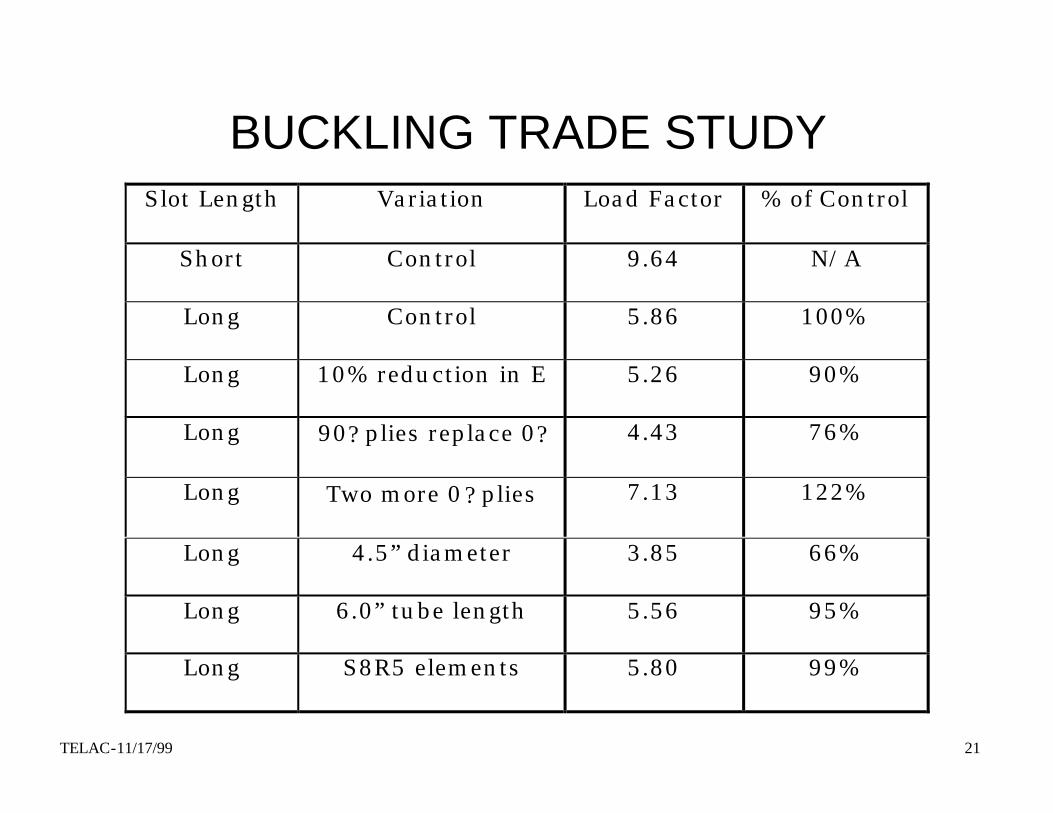
BUCKLING TRADE STUDYSlot Length Variation Load Factor % of Control
Short Control 9.64 N/A
Long Control 5.86 100%
Long 10% reduction in E 5.26 90%
Long 90? plies replace 0? 4.43 76%
Long Two more 0? plies 7.13 122%
Long 4.5” diameter 3.85 66%
Long 6.0” tube length 5.56 95%
Long S8R5 elements 5.80 99%
TELAC-11/17/99 22
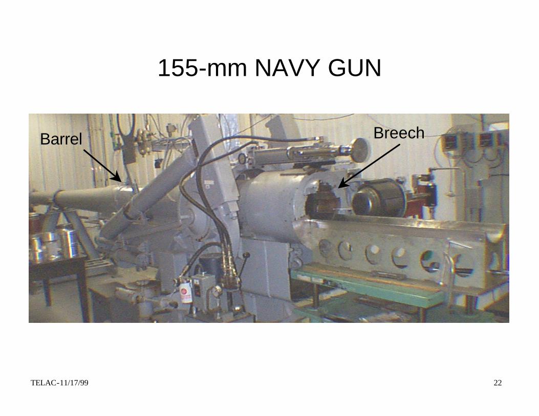
155-mm NAVY GUN
BreechBarrel
TELAC-11/17/99 23
AIR-GUN TESTING
• Six samples with same configuration as compression tests
• Both slot lengths survived 10,000 g’s– equivalent to 40,000 lbs with 4 lbs block– below threshold measured for compressive tests
• Both failed catastrophically at 15,000 g’s – equivalent to 60,000 lbs with 4 lbs block– exceeds both 45,000 and 55,000 lbs measured failure limits
• Some uncertainty in g-level estimation

TELAC-11/17/99 24
CONCLUSIONS
• Models– weight can be saved using composites over Al design– ABAQUS model accurate for predicting failure modes– FEA + CLPT + Tsai predicts failure loads with error
• Testing– compression testing correlates well with air-gun– can potentially save much money and time
• Design– preliminary design criteria using static + dynamic FEA – knockdown factor of 1.25 for failure criteria obtained

FUNCTIONAL TEST ARTICLE
Manufacture and Integration of Composite Body and Wing
Sections
TELAC-11/17/99 26
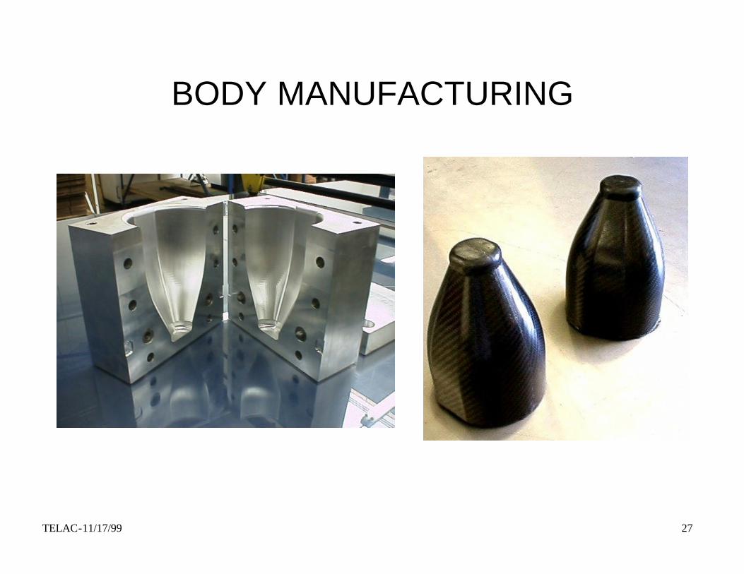
COMPOSITE BODY
• 3 parts: Nose, Wing and Tail sections
• Compression molding by Quatro Composites?
– Graphite fibers, 33 msi
– High temperature / high strength epoxy system
– .1” wall thickness, 20 fiber layers
• Machined with diamond grit carbide tools
• Sections joined with Al or Ti inserts, bonded & bolted
• Designed to be g-hardened from previous static and dynamic FEA, tests of composite cylinders
TELAC-11/17/99 27
BODY MANUFACTURING
TELAC-11/17/99 28
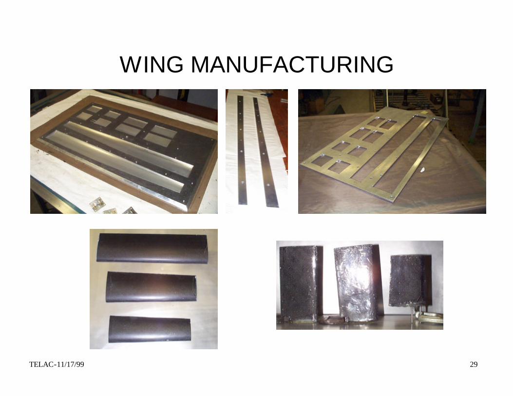
COMPOSITE WINGS
• All aero-surfaces made in composite– 3 part hinged wing sections, thin cambered airfoil
– 2 part telescoping vertical rudder
– 1 part horizontal tail fin sections, symmetric airfoil
• Made by hand “wet” lay-up at MIT– Graphite woven ?45? fabric and unidirectional tape
– Taper of 28 layer leading to 12 layer trailing edge
– West System? epoxy with colloidal silica thickener
– Open faced molds, vacuumed room temp cures
• Sized from WASP I work (Jenkins, Radcliffe)
TELAC-11/17/99 29
WING MANUFACTURING
TELAC-11/17/99 30
MANUFACTURING PROCEDURECure #1: Wet Lay-up of all aero-surfaces on mold
Cure #2: Excess fabric cut away with templateBond tail fin surfaces together with chopped fiberBond top rudder piece with metal posts for springsWrap fabric around lower rudder piece with mandrelSecondary cure of leading edges
Cure #3: Sand all edges of aero-surfacesFinishing coat of epoxy on tail and rudder surfacesChopped fiber ledges built for hinges
Cure #4 Spring loaded hinge bonded to ledged on one sideFabric bonded over hinge to prevent delamination
Cure #5 Hinge bonded to other ledge with covering fabric
Cure #6 Neoprene filler bonded in hinge gap

TELAC-11/17/99 31
HINGE MECHANISM
Finished hinge mechanism
Hinge with dihedral stop
Folded 3-part wing
Chop-fiber ledge for hinge

TELAC-11/17/99 32
FUTURE WASP WORK
• Testing
– static tests on composite body parts, wings and hinges
– air-gun tests of structure and on all components
• Analysis
– Integrate composite failure tool in ANSYS
– Analyze and optimization of all WASP composite parts
• Production
– Design of production scale vehicle, 1000/year for 10 years
– Proof test of flight ready, g-hard vehicle in 2002