design and implementation of ftth network based...
TRANSCRIPT
ISSN: 2347-971X (online) International Journal of Innovations in Scientific and ISSN: 2347-9728(print) Engineering Research (IJISER)
www.ijiser.com 209 Vol 4 Issue 11 Nov 2017/101
DESIGN AND IMPLEMENTATION OF FTTH NETWORK BASED ON GPON
TECHNOLOGY
Femey Rose1 , Dr. Sunil Jacob
2 , Renjith R
3
1 Assistant Professor, AISAT School of Engineering & Technology, Kalamassery, Kerala
2Professor, Department of Electronics and communication, SSET, Ernakulam, Kerala
3Technical Assistant, Sun Fiber Optics, Nest, Kakkanad, Kerala, India
Abstract—Fiber to the Home provides best transmission possibilities to conventional wired or wireless techniques.
It offers advantages such as high bandwidth, immunity against interference, low cost & flexible designs, makes the
telecom operators to choose FTTX networks. FTTH based on GPON technology is the most efficient method for
FTTH implementation since it provides triple play, high splitting ratio, low CAPEX (Capital expenditure) and
OPEX (Operational expenditure) , high speed transmission and so on. This design proves the allocation of maximum
number of users for a multi dwelling buildings with tolerable power budget and cost. This design is also capable to
incorporate future services like IPTV and provides dynamic allocation of bandwidth (DAB) according to the user
requirements. INAS EMS software is used to show the active ports, diagnose the issues by fire alarm settings,
physical / logical topological configuration support etc. after the network implementation.
Keywords—Fiber to the Home (FTTH), Passive optical network (PON) , Optical network terminal (ONT), Optical
line terminal (OLT), Gigabit Passive optical network (GPON).
1. INTRO DUCTIO N
The requirement such as high bandwidth and capacity,
high speed internet, HDTV, VoIP causes the thought
for FTTX access networks. FTTH based on GPON
technology is one of the techniques which can provide
triple play services at a reasonable cost. It uses only
passive equipment’s except at central office (CO) and at
the customer premises. Now most of the telecom
operators uses FTTH network based on GPON due to
its flexibilities in handling extended technologies and
services in future. For a GPON technology maximum of
128 uses can be included in a network with maximum
reachability of 60 km and maximum distance between
concecutive ONTs of 20 km as per G.984.6 ITU-T
specification [8]. It uses tree topology to maximize the
coverage with minimum network splits thus reducing
optical power [7]. GPON uses 2.44 Gbps downstream
with AES encryption and 1.24 Gbps upstream data
transmission. Broadcasting or continuous transmission
for downstream and TDM technique for upstream are
used as transmission method.
In this paper, the validation of proposed design is
done on the basis of power budget and cost. The results
shows that the received power levels falls within
tolerable power budget and the consumed cost is low
compared to other networks. INAS EMS software is
used to check the connectivity’s , active ports location
diagonisation of ONTs etc. The different profile
configurations like ONU profile, VoIP profile ,DBA
(Dynamic Bandwidth Allocation) profile are also done
to have different services. This paper includes different
sections like Components of GPON network, design,
Implementation, testing results, and finally the
conclusion.
2. COMPONENTS OF GPON FTTH NETWORK
A Passive Optical Network (PON) is capable of having
P2M (point to multipoint) network with passive
components like optical splitter or coupler along the
transmission section. It uses active components only at
CO and at customer premises. It uses WDM to mix up
video signals with the data and voice from OLT. The
Figure.1 shows the basic FTTH Network.

ISSN: 2347-971X (online) International Journal of Innovations in Scientific and ISSN: 2347-9728(print) Engineering Research (IJISER)
www.ijiser.com 210 Vol 4 Issue 11 Nov 2017/101
Figure 1: FTTH Network [7]
2.1 Optical Line Terminal (OLT)
It is the most important part of the network, where the
electrical signal from the service provider’s equipment
are converted into optical signals and given to the
feeder network. The mode of transmission from ONT is
broadcasting [8] from where it sends GEM frames
through the GEM port with GEM port IDs It is capable
of having Multi-service chassis for FTTx deployments,
Supports a variety of service types, Non-blocking
architecture with & Routing within distributed
architecture, scalability and line rate performance, Full
electrical and optical redundancy Outstanding
scalability and line rate performance, Real-time
network traffic monitoring and analysis .V8240 GPON
OLT is used. Specifications are given in the table 1.
Table 1: V8240 GPON OLT Specifications.
2.2 Optical Network Terminal (ONT)
It is an active component used at customer premises
which converts optical to electrical signals. ONU/ONT
represents the single customer where they will get the
triple play application. H640 series GPON ONT are
used. It is capable of having carrier class VoIP
telephony supporting both MGCP and SIP protocols,
Flexible VLAN tagging support, QoS for traffic
prioritization and bandwidth management, IGMP
support for IPTV applications. Its specifications are
given in table 2.
Table 2: H640 Series GPON ONT
2.3 Splitter
Splitters are used to physically split the fiber to number
of fibers; to couple same or different information’s to N
users. MxN planar splitters are used which is based on
planar light wave circuit (PLC) technology and high
precision alignment. MxN splitters can split or combine
light from one or two fibers into N outgoing fibers
uniformly over a wide spectral range with ultra-low
insertion loss and low polarization dependent loss. With
upto 64 output ports, these splitters are ideal for high
density split applications like Fiber To The Home
(FTTH) networks, FTTx Deployments Optical CATV
Networks, CWDM and DWDM Systems, Passive
Flash Memory 72 MB
SDRAM 1 GB
Dimensions (W x
H x D)
17.1 x 12.2 x
11.2 in (434 x
310 x 285 mm)
Switching Capacity 296Gbps
Power Voltage AC
type
100-240VAC,
50/60Hz
DC type -48/60VDC
Operating Temp 32 to 122°F (0
to 50°C)
SIU (Subscriber
Interface Unit)
10 slots
NIU (Network
Interface Unit)
2 slots
SFU (Switching
Fabric Unit)
2 slots
Service
Interface
4 10/100Base-TX ports (RJ45)
2 POTS ports (RJ11)
1 RF video port (F-connector)
Uplink
Interface
1 GPON port (SC/APC type)
Operatin
g Temp
32 to 104°F (0 to 40°C)
Storage
Temp
-4 to 140°F (-20 to 60°C)
Input 100-240VAC
Dimensio
ns (W x
H xD)
• Excluding bracket:10.24 x 2.05
x 7.87 in (260 x 52 x 200 mm)
• Including bracket, wall
mounting:10.51 x 2.60 x 7.87 in
(267 x 66 x 200 mm)
• Excluding bracket, desktop
mounting: 10.24 x 2.80 x 7.87
in (260 x 71 x 200 mm)
ISSN: 2347-971X (online) International Journal of Innovations in Scientific and ISSN: 2347-9728(print) Engineering Research (IJISER)
www.ijiser.com 211 Vol 4 Issue 11 Nov 2017/101
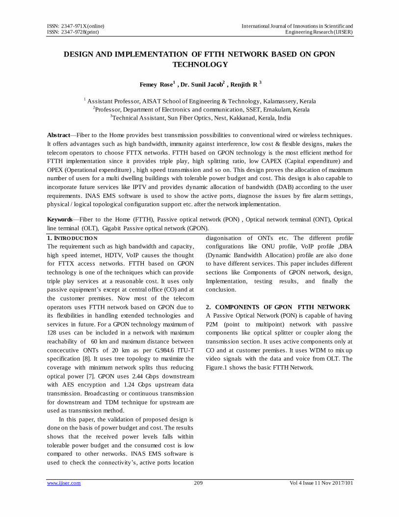
Optical Networks, Fiber Communication Systems
Telecom, LANs. It has the features like Low Insertion
Loss, Ultra broadband performance (1260 –
1630nm),Low PDL and PMD, Stable towards thermal
variations, Superior port to port uniformity. A splitter
type is shown in Figure.2
Figure 2: PLC splitter with Ribbon fiber
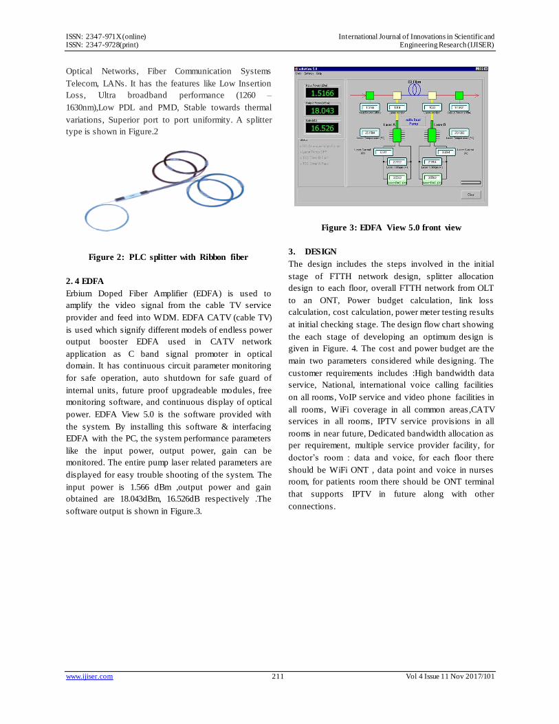
2. 4 EDFA
Erbium Doped Fiber Amplifier (EDFA) is used to
amplify the video signal from the cable TV service
provider and feed into WDM. EDFA CATV (cable TV)
is used which signify different models of endless power
output booster EDFA used in CATV network
application as C band signal promoter in optical
domain. It has continuous circuit parameter monitoring
for safe operation, auto shutdown for safe guard of
internal units, future proof upgradeable modules, free
monitoring software, and continuous display of optical
power. EDFA View 5.0 is the software provided with
the system. By installing this software & interfacing
EDFA with the PC, the system performance parameters
like the input power, output power, gain can be
monitored. The entire pump laser related parameters are
displayed for easy trouble shooting of the system. The
input power is 1.566 dBm ,output power and gain
obtained are 18.043dBm, 16.526dB respectively .The
software output is shown in Figure.3.
Figure 3: EDFA View 5.0 front view
3. DESIGN
The design includes the steps involved in the initial
stage of FTTH network design, splitter allocation
design to each floor, overall FTTH network from OLT
to an ONT, Power budget calculation, link loss
calculation, cost calculation, power meter testing results
at initial checking stage. The design flow chart showing
the each stage of developing an optimum design is
given in Figure. 4. The cost and power budget are the
main two parameters considered while designing. The
customer requirements includes :High bandwidth data
service, National, international voice calling facilities
on all rooms, VoIP service and video phone facilities in
all rooms, WiFi coverage in all common areas ,CATV
services in all rooms, IPTV service provisions in all
rooms in near future, Dedicated bandwidth allocation as
per requirement, multiple service provider facility, for
doctor’s room : data and voice, for each floor there
should be WiFi ONT , data point and voice in nurses
room, for patients room there should be ONT terminal
that supports IPTV in future along with other
connections.

ISSN: 2347-971X (online) International Journal of Innovations in Scientific and ISSN: 2347-9728(print) Engineering Research (IJISER)
www.ijiser.com 212 Vol 4 Issue 11 Nov 2017/101
Figure 4: Design Flow Chart
The FTTH network design showing the
transmission from OLT to one ONT is shown in
Figure.5. The video signals are given to EDFA where
there is an isolator to have the transmission only in one
direction and transmitted at 1550nm and the voice , data
are given to OLT to convert to optical signal and
transmitted at 1310nm.WDM mixes these two signals
from EDFA and OLT.
Figure 5: FTTH network design
The splitter allocation in each floor is designed
considering the insertion losses, power transmitted and
received at OLT and ONT. The power and the losses
are calculated using the power meter testing. The
splitter allocation design is shown in Figure.6 which is
drawn using coral drawing and power ,insertion losses
(IL) calculated are given in table 3. This design is
flexible to accommodate future extensions to each
floor. Even though the design is made upto 9th
floor ,
the implementation is performed only upto 5th
floor as
per the customer requirement.
Figure 6: Splitter allocation design
Table 3: Power and Losses in the Components

ISSN: 2347-971X (online) International Journal of Innovations in Scientific and ISSN: 2347-9728(print) Engineering Research (IJISER)
www.ijiser.com 213 Vol 4 Issue 11 Nov 2017/101
Power budget, link loss and cost are calculated using
the following equations:
Rx power at ONT = min tx of OLT – (patch cord A
max IL + patch cord B IL + splitter max IL + riser cable
(C) IL + drop cable (D) IL ).
Rx power at ONT = tx power at OLT – ( all losses
along the path from OLT to ONT).
Patch cord A : OLT to WDM and splitter
Patch cord B : splitter to patch panel.
Link loss = total length of fiber x attenuation (dB/km) +
no. of splices x splicing loss + no. of connector x
connector loss.
Total loss = Link loss + safety margin (3 dB).
Total cost = active component cost + passive
component cost+ labor cost including implementation
and maintenance cost.
Using these equations, the results are shown in
table 4. The number of splices and connectors in each
link are 4 and 9 respectively. Standard values of splice
loss and connector loss are taken which is equal to
0.3dB/km and 0.75 dB respectively. Using this link loss
= 7.168 dB & total loss = 10.168 dB. Only at OLT we
use the connector type as SC-PC and all the other
sections SC-APC is used. Transmit power for ONT and
OLT are 1.5 dBm and the maximum tolerable power
receive is -28 dBm.
Table. 4 Received power levels in ONT
4. IMPLEMENTATION
The optimal design leads to implementation of the
FTTH network. The design is done for 9 floors
including the future works. This is a green field project
for the implementation of FTTH network based on
GPON in a new building which consists of :Ground
Floor : MRI scan, consult, reception, First floor:
endoscopy , nurse’s room, ICU, consult, pre/post-
operative room, Second floor: Doctor’s room, nurse’s
room, consult room, nuero lab, Urodynamic, Third floor
: not assigned, Fourth floor : consult room, Fifth Floor :
Pathologists, lab in charge room, staff room, reception,
lab tech/data entry, serology lab, TTD lab ,
cytopathologist’s room. The implementation procedure
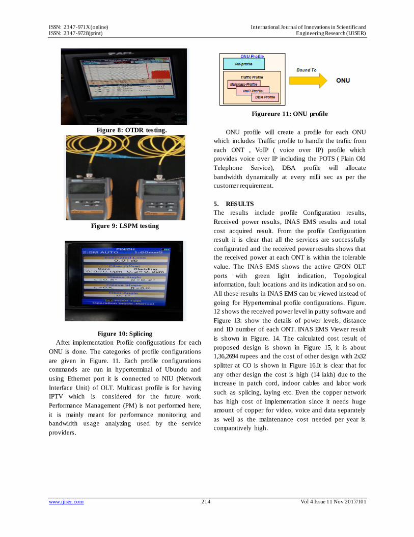
is shown in the Figure. 7 . For testing, the methods used
are OTDR and LSPM. Optical Time Domain
Reflectrometry (OTDR) will launch the light into the
network and it will used to measure the total length of
the fiber, loss of fiber, connector, splice, bent positions
and break point detection by using any one of the
following output trace, table and summary. It can’t be
used for power measurement. Figure. 8 shows the
OTDR testing. Light source and power meter (LSPM)
testing is a type of testing which uses a light source as
laser and power meter to test the loss and power in the
equipments. Figure.9 shows the LSPM testing.
Figure 7: Implementation flow chart
Noise M210 OTDR , a product of AFL (American
Fugikura Ltd ) , Fugikura 80S splicer and F2H product,
FHP1 series of power meter were used for OTDR
testing, splicing and LSPM testing. Figure.10 shows the
spicing.
ISSN: 2347-971X (online) International Journal of Innovations in Scientific and ISSN: 2347-9728(print) Engineering Research (IJISER)
www.ijiser.com 214 Vol 4 Issue 11 Nov 2017/101
Figure 8: OTDR testing.
Figure 9: LSPM testing
Figure 10: Splicing
After implementation Profile configurations for each
ONU is done. The categories of profile configurations
are given in Figure. 11. Each profile configurations
commands are run in hyperterminal of Ubundu and
using Ethernet port it is connected to NIU (Network
Interface Unit) of OLT. Multicast profile is for having
IPTV which is considered for the future work.
Performance Management (PM) is not performed here,
it is mainly meant for performance monitoring and
bandwidth usage analyzing used by the service
providers.
Figureure 11: ONU profile
ONU profile will create a profile for each ONU
which includes Traffic profile to handle the trafiic from
each ONT , VoIP ( voice over IP) profile which
provides voice over IP including the POTS ( Plain Old
Telephone Service), DBA profile will allocate
bandwidth dynamically at every milli sec as per the
customer requirement.
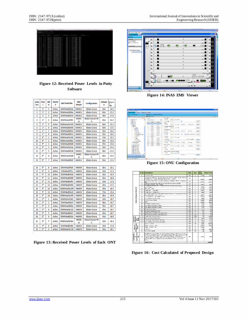
5. RESULTS
The results include profile Configuration results,
Received power results, INAS EMS results and total
cost acquired result. From the profile Configuration
result it is clear that all the services are successfully
configurated and the received power results shows that
the received power at each ONT is within the tolerable
value. The INAS EMS shows the active GPON OLT
ports with green light indication, Topological
information, fault locations and its indication and so on.
All these results in INAS EMS can be viewed instead of
going for Hyperterminal profile configurations. Figure.
12 shows the received power level in putty software and
Figure 13: show the details of power levels, distance
and ID number of each ONT. INAS EMS Viewer result
is shown in Figure. 14. The calculated cost result of
proposed design is shown in Figure 15, it is about
1,36,2694 rupees and the cost of other design with 2x32
splitter at CO is shown in Figure 16.It is clear that for
any other design the cost is high (14 lakh) due to the
increase in patch cord, indoor cables and labor work
such as splicing, laying etc. Even the copper network
has high cost of implementation since it needs huge
amount of copper for video, voice and data separately
as well as the maintenance cost needed per year is
comparatively high.
ISSN: 2347-971X (online) International Journal of Innovations in Scientific and ISSN: 2347-9728(print) Engineering Research (IJISER)
www.ijiser.com 215 Vol 4 Issue 11 Nov 2017/101
Figure 12: Received Power Levels in Putty
Software
Figure 13: Received Power Levels of Each ONT
Figure 14: INAS EMS Viewer
Figure 15: ONU Configuration
Figure 16: Cost Calculated of Proposed Design

ISSN: 2347-971X (online) International Journal of Innovations in Scientific and ISSN: 2347-9728(print) Engineering Research (IJISER)
www.ijiser.com 216 Vol 4 Issue 11 Nov 2017/101
Figure 17: Cost Calculated for 2x32 Splitter
Design
6. CONCLUSION
The results shows the above mentioned design of FFTH
network based on GPON technology is an optimum
design which has tolerable power budget and the cost of
implementation of this particular design is
comparatively low than the other network designs. It is
proven that the above design can include extended
versions of technology and services like IPTV in future.
7. ACKNOWLEDGMENT
This work described in this paper is carried out with the
support of SFO (Sun Fiber Optics) Technologies,
NeST, DASAN Networks, funded by Sunrise Hospital ,
Kakkanad, Kerala, India. This work was supported by
Sun Fiber Optics, a NeST Group Company, DASAN
Networks and Funded by Sunrise Hospital , Kakkand ,
Kochi, Kerala, India.
Figure 18: Central Office
Figure 19: FTB with Splitter
Figure 20: WiFi ONT
REFERENCES
[1] S. Chatzi et al., ―Techno-economic comparison of
current and next generation long reach optical access
networks‖, in 9th conference on Telecommunications
Internet and Media Techno Economics (CTTE),IEEE
Conference publications,pp.1-6,2010.
[2] S.Kulkarni and M. El-Sayed, ―FTTH-Based Broadband
Access Technologies: Key Parameters for Cost
Optimized Network Planning‖,in Bells Labs Technical
Journal,vol.14,no.4,2010.
[3] A.Ouali and K.F. Poon, ―Optimal Design of
GPON/FTTH networks using Mixed Integer Linear
Programming‖, in Networks and Optical
Communications(NOC),IEEE 9th International
Conference, 2011.

ISSN: 2347-971X (online) International Journal of Innovations in Scientific and ISSN: 2347-9728(print) Engineering Research (IJISER)
www.ijiser.com 217 Vol 4 Issue 11 Nov 2017/101
[4] J.Segarra et al., ―Planning and Designing FTTH
Networks: Elements,Tools and Practical Issues‖, in 14th
International Conference on Transparent Optical
Networks(ICTON),IEEE Conference publications,pp.1-
6,2012.
[5] A. Ouali et al., ―FTTH Network Design Under Power
Budget Constraints‖, in IFIP/IEEE International
Symposium on Integrated Network management(IM
2013),pp.748-751,2013.
[6] D.J. Kadhim and N.A.R.Hussian, ―Design and
Implementation of a practical FTTH Network‖,in
International Journal of Computer
Applications,vol.72,no.12,June 2013.
[7] M.M. Al-Quzwini, ―Design and Implementationof a
Fiber To The Home FTTH Access Network based on
GPON‖,in International Journal of Computer
Applications,vol.92,no.6,April 2014.
[8] ITU-T G.984 Gigabit Passive Optical Network
Specifications