design and implementation of bundle protocol stack for ...lib.tkk.fi/dipl/2006/urn007387.pdf ·...
TRANSCRIPT
HELSINKI UNIVERSITY OF TECHNOLOGY
Department of Electrical and Communications Engineering
Omar Mukhtar
Design and Implementation of Bundle Protocol Stack for
Delay-Tolerant Networking
Master’s thesis submitted in partial fulfillment of the requirements for the degree of Master of Science in Technology
Supervisor: Professor Jörg Ott (Networking Laboratory)
Espoo, 11th August 2006
HELSINKI UNIVERSITY OF TECHNOLOGY Abstract of the Master’s thesis
Author: Omar Mukhtar
Name of the Thesis: Design and Implementation of Bundle Protocol Stack for
Delay-Tolerant Networking
Date: 11.08.2006
Pages: 94
Department:
Professorship:
Department of Electrical and Communication Engineering
Networking Technology
Supervisor: Professor Jörg Ott
The Internet family of protocols (TCP/IP) has dominated the computer network
communications; offering services such as worldwide web (WWW), file transfer (FTP),
e-mail and voice-over-IP (VoIP) to the scientific, research and business communalities
and to the common users. The TCP/IP protocols are also merging with other
telecommunication paradigms such as 3G and 4G cellular networks. Despite of wide
deployment, TCP/IP protocols are ill suited for some extreme networks because of some
strict fundamental assumptions regarding end-to-end communication, built-into their
architecture. These assumptions do not always hold in the emerging challenged
networks such as mobile ad hoc networks, deep space communication, sensor networks,
low earth orbiting (LEO) satellites etc., because of variable requirements of bandwidth,
longer end-to-end delays, intermittent connectivity and higher error rates.
Delay-Tolerant Networking tries to solve some of the issues by relaxing many of the
assumptions used in the TCP/IP regarding end-to-end communication. It defines an
overlay network for end-to-end message delivery, which uses the Bundle protocol. In
the thesis work, we have implemented the Bundle protocol stack for Symbian based
smart phones to extend DTN for mobile phone based interpersonal communication and
the networks formed by socializing of people. We have also designed and implemented
a convergence layer for Bluetooth. The software architecture is generic, extensible and
provides API for the development of customized DTN applications for mobile phones.
Keywords: Delay-Tolerant Networking, Bundle protocol, Symbian application design.
ii

Foreword
This Masters of Science thesis was written in Networking Laboratory in Helsinki
University of Technology. The thesis works was carried out the under the supervision of
Professor Jörg Ott.
I would like to thank Professor Ott for giving me the opportunity to work under his
supervision. He has provided invaluable inspirations, guidance and encouragement
during the entire course of the thesis work. He has been very friendly and supportive;
especially when the deadlines used to be close and during the reviews of this literature.
I also appreciate the support from the laboratory staff, especially to the department
secretary Raija Halkilahti and her coordinator Arja Hänninen. I especially thank to the
study program coordinator Mrs Anita Bisi for her support in finalizing the timely
submission of the thesis.
Finally, I express my deepest gratitude to my family for their prayers and encouragement.
Omar Mukhtar
Espoo, August 8, 2006.
iii
Table of Contents
Foreword ............................................................................................................................ iii
Table of Contents............................................................................................................... iv
Abbreviations and Acronyms ........................................................................................... vii
1. Introduction................................................................................................................. 1
1.1. Internet Protocols – Pros and Cons..................................................................... 1
1.2. Delay and Tolerant Networking.......................................................................... 4
1.3. Background and Related Work........................................................................... 6
1.3.1. InterPlaNetary (IPN) Internet ..................................................................... 7
1.3.2. Disconnected MANETs .............................................................................. 7
1.3.3. Nomadic Networks ..................................................................................... 8
1.4. Motivation of the Thesis Work ........................................................................... 8
1.4.1. Similar Work............................................................................................. 10
1.5. Outline of Thesis Work..................................................................................... 10
1.6. Summary ........................................................................................................... 11
2. DTN – Architecture and Protocol Specifications ..................................................... 12
2.1. DTN Architecture ............................................................................................. 12
2.1.1. Key Architectural Principles..................................................................... 13
2.2. Network Hierarchy and Protocol Stack ............................................................ 16
2.3. DTN Family of Protocols.................................................................................. 18
2.3.1. Protocol Design Principles........................................................................ 18
2.3.2. Bundle Protocol ........................................................................................ 22
2.3.3. Convergence Layer Protocols ................................................................... 27
2.3.4. Routing Protocols...................................................................................... 31
2.3.5. Neighbor Discovery .................................................................................. 32
2.4. Summary ........................................................................................................... 33
3. Implementation Architecture .................................................................................... 34
3.1. Conceptual Model of Bundle Node .................................................................. 34
3.1.1. Bundle Protocol Agent.............................................................................. 35
iv

3.1.2. Convergence Layers.................................................................................. 35
3.1.3. Application Agent..................................................................................... 35
3.2. Architecture for Symbian OS............................................................................ 36
3.2.1. Symbian OS .............................................................................................. 36
3.2.2. Top-level Architecture .............................................................................. 37
3.3. Summary ........................................................................................................... 40
4. Programming for Symbian OS and Design Patterns................................................. 41
4.1. Programming for Symbian OS.......................................................................... 41
4.1.1. Code Optimization .................................................................................... 42
4.1.2. Clean-up Stack & Leave Mechanism ....................................................... 43
4.1.3. Thin Templates ......................................................................................... 44
4.1.4. Active Objects........................................................................................... 44
4.1.5. Naming Conventions ................................................................................ 45
4.1.6. Strings and Binary Data ............................................................................ 45
4.1.7. Client-Server Framework.......................................................................... 46
4.2. Design Patterns ................................................................................................. 46
4.2.1. Model-View-Controller Pattern ................................................................ 46
4.2.2. Observer Pattern........................................................................................ 47
4.3. Summary ........................................................................................................... 48
5. Design and Implementation Details.......................................................................... 49
5.1. Utility Classes ................................................................................................... 49
5.1.1. FNV Hash ................................................................................................. 49
5.1.2. EID............................................................................................................ 50
5.1.3. SDNV........................................................................................................ 51
5.1.4. Schedular-Timer ....................................................................................... 53
5.1.5. Event-Notifier ........................................................................................... 53
5.2. Convergence-Layer Adapter Classes................................................................ 54
5.2.1. Connection Classes ................................................................................... 54
5.2.2. CLA Classes.............................................................................................. 55
5.3. Bundle Protocol Agent Classes......................................................................... 59
5.3.1. BPA Class ................................................................................................. 59
v

5.3.2. Bundle and Admin-Record Classes .......................................................... 62
5.3.3. BP-Router Class........................................................................................ 63
5.3.4. EID Lookup Record Class ........................................................................ 65
5.4. Application Agent Classes................................................................................ 65
5.4.1. Symbian Client-Server Framework Classes ............................................. 66
5.4.2. DTNServer Class ...................................................................................... 66
5.4.3. DTNSession Class .................................................................................... 67
5.5. User Interface Classes....................................................................................... 68
5.6. DTN Applications............................................................................................. 69
5.6.1. DTN-Socket Class .................................................................................... 69
5.6.2. Application Design Principles .................................................................. 70
5.6.3. Application Design Example .................................................................... 71
5.7. Summary ........................................................................................................... 72
6. Verification and Demonstration................................................................................ 73
6.1. Verification ....................................................................................................... 73
6.1.1. Functional Testing .................................................................................... 74
6.1.2. Interoperability Testing............................................................................. 75
6.1.3. Performance Testing ................................................................................. 75
6.2. Demonstration Setup......................................................................................... 77
6.3. Software Release............................................................................................... 79
6.4. Summary ........................................................................................................... 80
7. Conclusions and Recommendations ......................................................................... 81
References......................................................................................................................... 84
vi

Abbreviations and Acronyms
AA Application Agent
API Application Programming Interface
BGP Border Gateway Protocol
BP Bundle Protocol
BPA Bundle Protocol Agent
CL Convergence Layer
CLA Convergence Layer Adapter
DLL Dynamically Linked Library
DTN Delay Tolerant Network(ing)
EGP Exterior Gateway Protocol
Gbps Giga bits per second
GPRS General Packet Radio Systems
GUI Graphical User Interface
HIP Host Identity Protocol
ID Identifier
IP Internet Protocol
IPC Inter-Process Communication
IPN InterPlaNetary
IPv4 IP version 4
IPv6 IP version 6
kbps kilo bits per second
LAN Local Area Network
MANET Mobile Ad hoc Network
Mbps Mega bits per second
MFC Microsoft Foundation Classes
MMS Multimedia Messaging Service
MVC Model View Controller
OOP Object Oriented Programming
vii

OS Operating System
PAN Personal Area Network
PDA Personal Digital Assistant
PPP Point-to-Point Protocol
QoS Quality of Service
RF Radio Frequency
RIP Routing Information Protocol
SDK Software Development Kit
SDNV Self-Delimiting Numeric Value
SDP Service Discovery Protocol
SMS Short Message Service
SPP Serial Port Profile
STL Standard Template Library
TCP Transmission Control Protocol
UDP User Datagram Protocol
UI User Interface
UML Unified Modeling Language
URI Uniform Resource Identifier
URL Uniform Resource Locator
UUID Universally Unique ID
VoIP Voice over IP
WLAN Wireless LAN
WTCP Wireless TCP
viii

1. INTRODUCTION
The first chapter provides an introduction, background and motivation of the t
It starts with a short analysis of success and failures of conventional and mos
deployed communication network, the Internet and its family of protocols
section presents a brief account of history, background and introduction
Tolerant Networking. Subsequent section discusses motivation and outline o
work. In the last section, an outline of material, presented in this document, is
1.1. Internet Protocols – Pros and C
During past two decades, the Internet has become widely deployed wi
popularity of its services such as e-mail, web and now VoIP. It has greatly
other communication networks, to an extent that conventional circuit-switche
are converging towards packet-based services, e.g. 3G and 4G. The Interne
protocols, also known as TCP/IP protocol suite, is becoming the basis of num
of applications and inter-networks. In fact, most of today’s PANs, MANs
follow an hour-glass paradigm, with IP protocol at the heart and a large
hesis work.
t commonly
. The next
of Delay-
f this thesis
provided.
ons
th extreme
influenced
d networks
t family of
erous kinds
and WANs
number of
1
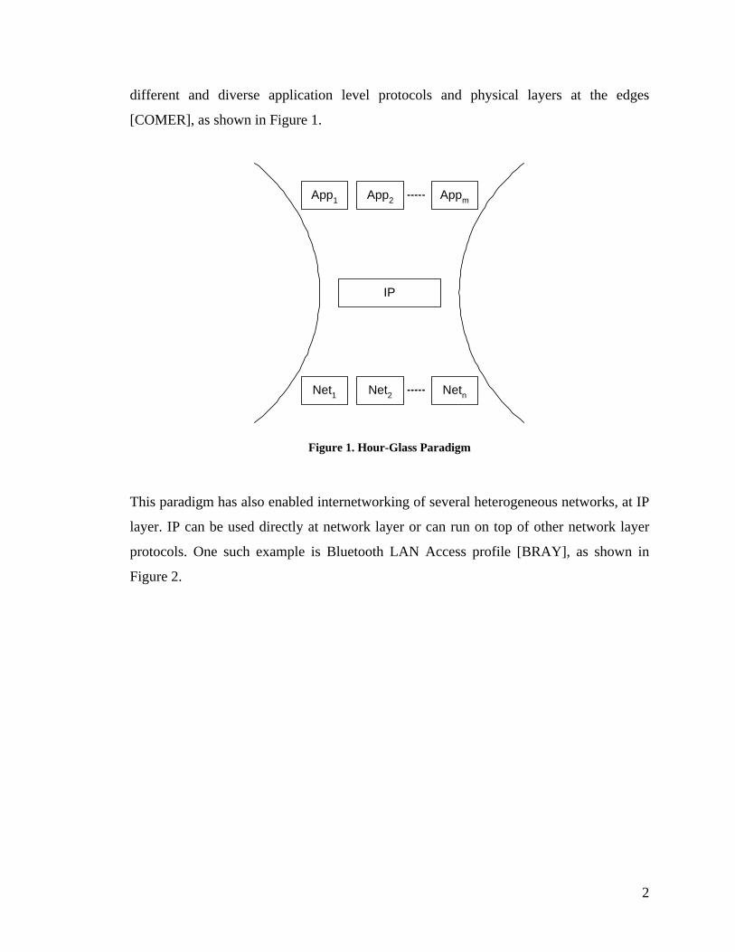
different and diverse application level protocols and physical layers at the edges
[COMER], as shown in Figure 1.
App1 App2 Appm
IP
Net1 Net2 Netn
Figure 1. Hour-Glass Paradigm
This paradigm has also enabled internetworking of several heterogeneous networks, at IP
layer. IP can be used directly at network layer or can run on top of other network layer
protocols. One such example is Bluetooth LAN Access profile [BRAY], as shown in
Figure 2.
2

Bluetooth Radio
Bluetooth Baseband
L2CAP
RFCOMM
PPP
IP
TCP/UDP
Figure 2. Bluetooth stack for LAN Access Profile
Despite of success and wide deployment of Internet family of protocols, the shortcomings
of TCP/IP are being observed by researchers as new heterogeneous networks and
communication paradigms are emerging, such as wireless networks, PANs, MANETs,
3G and 4G cellular technologies, and seamless ubiquitous and pervasive connectivity
[BALA97].. The Internet and TCP/IP protocols were built using some fundamental
assumptions for underlying network architecture, which do not hold when TCP/IP
protocols are adapted in emerging networks and communication paradigms. Researchers
have proposed different solutions to fix some of the problem, but mainly it turns out to be
‘one solution for one problem’ model. Some issues and proposed solutions as described
below.
TCP/IP protocols assume end-to-end connectivity, low error rates, small end-to-end
delays, and many algorithms are built over these assumptions. With the advent of mobile
wireless networks in particular, the flaws posed by these assumption becomes evident.
For example, TCP slows down the transmission assuming congestion in the network
rather than loss of packets. In wireless networks, on the contrary, error rates are quite
high and TCP throughput is degraded significantly, because TCP should transmit more
vigorously. Researchers proposed some solutions to improve the performance of TCP,
but the problem cannot be eliminated entirely because of end-to-end connectivity model
3
[TANENBAUM] [BPSK97]. With the growth in usage of Internet, wireless networks and
cellular networks, mobility and multi-homing issues have become evident as well.
Mobile devices such as laptops, smart-phones, PDAs have become sophisticated
computing and communication machines, often equipped with multiple communication
interfaces. A single TCP connection maps to one IP address for an entire session, and
hence multiple communication links each identified by a different IP address cannot be
used for a single session, taking advantages of multi-homing or vertical handovers.
Mobile IP [RFC2002] and Host Identity Protocol (HIP) [RFC4423] propose independent
solutions for such problems. Routing between IP and non-IP networks has also been
investigated especially for VoIP and circuit-switched telephony, and solutions such as
ENUM [RFC2916] have been proposed.
With the advent of wireless and mobile networks and devices, the demand for ubiquitous
and pervasive connectivity is also increasing. Despite efforts to increase coverage area of
network and communication services, studies and research efforts indicate that
intermittent connectivity is becoming a rule rather than an exception [OTT04] [SESB05]
[BAIG06]. Intermittent connectivity is also evident in sparse ad hoc networks. TCP/IP
protocols fail as end-to-end model breaks again.
Besides all the research efforts mentioned above to mend the Internet, research is going
on to design new communication paradigms that do not follow some of the basic
assumptions strictly, upon which Internet TCP/IP protocols were built. One such effort is
delay tolerant networking, which aims at a variety of challenged, extreme and stressed
networks.
1.2. Delay Tolerant Networking
As described in last section, existing Internet protocols do not work well in some
environments, due to some strict fundamental assumptions built-into the architecture.
Delay-tolerant networking is an emerging communication paradigm that tries to solve
some of the issues described earlier. The DTN architecture has conceived to relax most of
4

those assumptions. Briefly, it relaxes end-to-end error control, continuous connectivity,
and very low propagation delays. It defines a layer-agnostic interconnection of
heterogeneous (IP and non-IP) networks by introducing a new internetworking layer with
relaxed requirements. DTN targets a broad range of challenged, stressed and extreme
networks, which cannot maintain end-to-end connectivity, have longer delays, or
infrequent interrupted connections. Such networks include deep space communication,
sensors-based network, satellite connections with periodic connectivity, sparse mobile ad
hoc networks etc. The major differences between these emerging networks and
conventional Internet are discussed in [BURL03] and [FALL03], and are summarized in
Table 1.
Table 1. Comparison of conventional Internet and emerging heterogeneous inter-networks
Conventional TCP/IP Internet Emerging Heterogeneous Inter-networks
Smaller signal propagation delays, order of
milliseconds, because of high-speed LANs
and Optic fibers.
Varied signal propagation delays, order of
up to several minutes, because of wireless
links, satellite channels.
High data rates, from a few Mbps to
several Gbps, in access networks and in
backbones.
Varied data rates from a few kbps, as in
PANs, to several Mbps, as in WLANs.
Often bidirectional communication on each
connection, because of same protocol suite
and similar policies across the connection
over Internet.
Possibly time-disjoint periods for
transmission and reception, due to multi-
path links and different policies among
differently managed dissimilar networks.
Continuous end-to-end connectivity.
Might be intermittent, scheduled or
opportunistic connectivity in dissimilar
heterogeneous environment.
Low end-to-end error rates, due to reliable
physical links, and error correction at
several layers of protocol stack.
High error rates, due to wireless links,
dissimilar protocol stacks etc.
Homogeneous protocols used at network A new paradigm of heterogeneous
5

and transport layers across the end-to-end
path; all nodes including end stations
support TCP/IP stack.
networks, protocol families and
management policies.
Single route selection between end nodes
for acceptable communication
performance.
Heterogeneous environment may not offer
a single bi-directional route.
Identical naming convention for routing
and delivery. Not possible among dissimilar networks.
Poor recovery mechanism in case of
temporary connection loss or hardware
failures/reboots. End-to-end
communication session needs to be re-
established.
End-to-end connection setup among
dissimilar and disjoint networks and
intermittent connections may not be viable
from practical point of view, due to less
time & cost efficiency.
Uniform routing schemes across end-to-end
path (RIP. BGP, EGP).
Complex disparate routing schemes
(epidemic routing, flooding, statistical,
multi-path routing etc.) used in different
regions of dissimilar networks across end-
to-end path.
1.3. Background and Related Work
This section describes the history and background of research efforts that have led to the
evolution of DTN and associated family of protocols. It also discusses other research
efforts with similar goals, which now can be combined with DTN. Initially, the research
efforts for Interplanetary Internet became the most fundamental basis for DTN
architecture and protocol suite. Later on, other research areas with similar problem set
were also included as requirement specifications. This resulted in a common protocol
suite for DTN, now known as bundle protocol. The research is going on under IRTF
umbrella.
6

1.3.1. InterPlaNetary (IPN) Internet
The history of DTN architecture dates back to late 1990’s when NASA started an effort
to investigate an IP-like protocol suite for communication across the solar system. This
research effort was termed as Interplanetary Internet, which aimed at an open, layered
and globally interoperable architecture supporting fairly long round trip delays between
the planets and astronomical equipments. During 1990’s, Internet has already dominated
being the biggest terrestrial communications network. Internet has been mostly wired to
high-speed fiber backbone, very low delays and negligible error rates. The backbone
offers symmetric data channels and is always-connected. IPN internet has to support both
wired (fiber, cable, copper) and wireless (satellites, WLAN, MANETs etc.) networks
with a number of challenging constraints, to become future’s communication network,.
These include significant delays, higher error rates, power and bandwidth limitations,
irregular connectivity and asymmetric channels [BURL03] [JACK05].
1.3.2. Disconnected MANETs
As practical applications of ad hoc networks are being investigated, new kinds of mobile
ad hoc networks are emerging and being deployed, termed as MANETs. These have
different sets of practical constraints, physical limitations, performance requirements and
data-delivery goals. They also use divergent set of protocols. Such MANETs also cannot
fulfill the stringent protocol requirements of TCP/IP family. Some details of such
MANETs are given below.
Sensornets
Sensor networks, also known as sensornets, is an ongoing research area in ad hoc
networks. Sensornets may have a sparse distribution of network nodes and data-retrieving
occasions are rare. Examples of such networks are: ZebraNet for wildlife monitoring
7

[JUANG02], whales and seals for water monitoring, data mules and message ferries
[ZHAO05] etc.
Disjoint Information Resource Access Networks
Some experimental networks have been deployed in remote areas to access information
resources, such as web and e-mail, where deployment of a permanent infrastructure is not
feasible. Data-nodes arrive from time to time to form an ad hoc network and provide
intermittent connectivity. Examples are Daknet [PENT04] in Cambodia and India, SNC
in Lapland [SNC], Wizzy in South Africa. Conventional TCP/IP protocols are not
feasible in such ad hoc infrastructure also.
1.3.3. Nomadic Networks
In order to access Internet via WLAN, while in a vehicle speeding on a long highway,
conventional infrastructure cannot work; other access networks (UMTS, satellite) being
too expensive or unavailable. There may be established some hot-spots along the way but
the intermittent connectivity is too short to work with conventional IP protocols based
communication for e-mail exchange, web-browsing etc. Hence conventional Internet
protocols fails here again. Drive-Thru Internet is an effort in similar directions in order to
define a non-conventional disruption tolerant architecture [OTT04]. Other efforts in
similar directions are DieselNet [BURG06], FleetNet [LOC03], Network-On-Wheels
[LEIG06] and in [SCH05].
1.4. Motivation of the Thesis Work
With increasing penetration of smart mobile phones and PDAs, a new kind of multi-hop
mobile ad hoc networking architecture is under investigation, termed as Social-Networks.
These personal devices are capable of wireless communications, often supporting more
8
than one link-layer technology, and people tend to always carry these devices with them.
This results in mobile ad hoc network as people meet at some place. The topology of
such mobile ad hoc networks is based on socialization behavior of the people, hence
termed as Social Networks [NEW04]. This is an on-going research area and new
architectures for communication, mobility modeling and routing are being investigated
by researchers [MUS06] [HUI05].
The motivation behind this thesis work is to implement and extend the DTN architecture
to smart mobile phones based MANETs. In particular, this work intends to provide a
DTN software framework, which could be used to investigate and explore DTN
applications in mobile ad hoc networks formed by smart phones. This could also help
investigating social networks formed by such mobile ad hoc networking.
Another interesting aspect of this research work is to provide a framework for smart
phone applications, which could effectively be configured to use multiple communication
links and networks in a ubiquitous fashion. Thus some of human-input responsibilities,
such as selection and configuration of multiple links and communication channels; user-
interaction in order to complete a communication operation, can be taken up by
communication applications themselves. This will hide such complex operations from
common users, enabling them performing data communication operations, such as file
transfer; web browsing; exchanging e-mails etc., seamlessly and more effectively in
disruptive, intermittent environments, like Drive-Thru Internet, social networks etc.,
which is not possible with conventional TCP/IP based architectures.
Symbian OS based smart mobile phones have been selected for this purpose. Symbian
OS has significant advantages over other peer technologies available such as:
Symbian-based smart mobile phones have more than one on-board link-layer
technologies available; like GPRS, MMS, WLAN, Infrared, and Bluetooth.
Symbian OS provides a generic abstraction for underlying communication
infrastructure, including telephony services, with a rich set of APIs.
9

Symbian OS offers a broad range of APIs to perform many primitive tasks for
handling communications, media and data, efficiently.
Symbian-based phones dominate the smart mobile phones market [SYMB06].
Good tools and SDKs are available to write sophisticated and larger software of
release quality.
Using native programming language for Symbian provides the advantage of
integrating protocol stack into the OS, in later stages.
1.4.1. Similar Work
DTN is an on-going research area. The specifications are still maturing. Many topics
have gathered intention of researchers including routing, naming-conventions, user-level
applications, link-layer convergence protocols etc. There is a reference implementation
available on the research group’s web page, for Linux. Although that has been ported on
some PDAs like Nokia 770 tablet1, yet there’s no known implementation for smart
mobile phones explicitly. There is a Java based simulator and Java implementation of
DTN [DTNRG]. There is also an implementation for TinyOS [PATRA04].
1.5. Outline of Thesis Work
An implementation of the Bundle protocol for Symbian based mobile phones has been
carried out during this thesis work. Interoperability testing has been performed against
reference implementation.
A brief background and motivation of this thesis work has been given in this introductory
chapter. Next chapters describe DTN architecture and associated family of protocols in
detail. A brief overview of Symbian OS and application design is also given, in order to
1 This porting work has also been carried out in Networking Lab Helsinki University of Technology by the
same research group.
10

facilitate extension of this work in future. Also a detailed design description is provided
in subsequent chapters. Finally, an example scenario is explained and demonstrated.
Appendices contain more details about design, and provide guidelines in order to build,
configure and use this implementation for further research, development and testing.
1.6. Summary
In this chapter, introduction and motivation to the thesis work was presented. A brief
review of related work was also given. DTN is an emerging communication paradigm for
challenged networks such as mobile ad hoc networks and other intermittent networking
scenarios. The thesis work aims at design an implementation of DTN applications for
mobile phones in order to provide a software framework for smart phones based inter-
personal communication over social networks. Next chapter discusses DTN architecture
and protocols in detail.
11
2. DTN – ARCHITECTURE AND PROTOCOL SPECIFICATIONS
This chapter starts with the description of architectural principles of De
Networking. Subsequent sections discuss the semantics of different
protocols.
2.1. DTN Architecture
As described in Chapter 1, the motivation behind DTN is to embrace unus
and challenged emerging networks. Such networks may have occasional
intermittent connectivity, long delays, and may comprise a divergent set
families. End-to-end communication across such networks using the I
protocols cannot be achieved due to various reasons described in previous ch
DTN is an overlay network of DTN nodes (nodes that participate in DTN
existing internets. DTN defines an abstraction layer on top of transport laye
application layers, called bundle layer. Although, some of the responsibili
lay-Tolerant
DTN-family
ual, extreme
or scheduled
of protocol
P family of
apter.
) on top of
rs and below
ties, such as
12

session management and synchronization on connection break ups [TANENBAUM],
makes it , analogous to Session layer in OSI model. Nevertheless, it is a full-fledged
internetworking layer, responsible for routing the data from source to destination. DTN
neither defines any fixed-length data units nor does put any upper or lower bounds on
application data unit size. It talks about messages, which a user wants to deliver to other
end. Bundle layer is responsible for end-to-end delivery mechanism of messages, called
virtual message forwarding [DTNARCH05].
As mentioned earlier, IPN formed the basis for DTN. The research efforts under IPNSig
led to DTN architecture, termed initially as Bundle Space, which defined core
requirements for IPN design. These include heterogeneous networks, long delays, short
contacts (possibly one-way), data being too expensive for end-to-end retransmissions
and smaller transaction size matching available bandwidth-delay product [IPN99]. This
led to key design decisions for IPN:
Deployment of an overlay network on top of existing internets, including
Internet, forming networks of internets with gateways and relay nodes to bridge
low latency environments with those with higher one.
Late binding of names to addresses; routing between internets is based on names.
Actual address translation may be performed very late in the overlay-network.
Relaying of data between heterogeneous environments depends upon
intermediate nodes. To cope with longer delays, a store-and-forward model
(similar to e-mail) is suitable.
Along with conventional proactive control of transaction size, reactive control
can lead to performance in disruptive environment.
2.1.1. Key Architectural Principles
The DTN Research Group refined the architectural principles further to incorporate all
kinds of extreme challenged and disruptive networks. They also elaborate on the
13

differences between delay-tolerant networking and convention inter-networking models,
especially the Internet [DTNARC05]. Some of the key points are summarized below:
Virtual Message Switching
Application data units are structured as variable-length messages, instead of limited size
packets. This abstraction is closer to user’s perspective of communication of data. A
message can be a huge file or a short e-mail message.
The communication abstraction of messages can also help enhance the ability of network
to make better decisions of routing, scheduling and path selection.
Naming and Addressing Mechanism: End-Point IDs
A generic naming syntax augmented with late binding to enhance interoperability
between heterogeneous internets. Late binding means that actual name-to-address
translation is carried out late in the delivery process. This concept does not require an
end-to-end connectivity prior to start of communication. The other advantage is that
routing between heterogeneous networks can be performed based on names, and hence
no address-to-address mapping mechanism is required prior to start of communication,
as opposed to DNS resolution in Internet.
Store and Forward Model
DTN uses a store-and-forward model like e-mail system. This breaks down the
requirement of having an end-to-end always connected path. Messages can be stored in
the network for longer periods. To increase reliability and to cope with hardware
failures, persistent storage is recommended. Whenever a scheduled or opportunistic link
becomes available, the network can deliver the message over that. Hence end-to-end
path connectivity is not required from the source node’s perspective.
14

Non-conversational Asynchronous Communication
DTN uses asynchronous, minimal conversational model that differs from conventional
query/response model of communication. Conventional services using the TCP/IP family
of protocols use end-to-end query/response model messages. For example FTP can use
up to 10 end-to-end transactions exchanged for a simple file transfer (requests and
responses for connection, log-on, transfer mode, directory services, file exchange, log-
off etc.). In an extreme environment of networking, including possibilities of
unidirectional links, such conversational models cannot work. DTN suggests a non-
conversational asynchronous model. So applications should be designed or adopted in a
way to minimize the end-to-end transactions, using larger self-contained messages.
Bundling
DTN suggests combining all application level data and metadata to form a single
bundled message, in order to minimize end-to-end transactions. For example, all FTP
metadata (login-name, password, file name(s) etc.) and actual data (file(s) if applicable)
can be sent to FTP server, bundled in one message. This is why DTN layer in protocol
stack is called Bundle Layer.
Routing
Routing in DTN networks is an area under research and has not been fully defined as
yet. Being in a heterogeneous environment with a divergent set of protocol families, the
possibilities of routing algorithm that can be used efficiently are numerous. DTN nodes
can deal with different types of communication links available, which may have different
requirements of delays, bandwidth, availability etc. Links, or as termed as contacts in
[DTNARCH05] can be:
Persistent (always-connected links like DSL)
On-demand (like persistent but require initial setup, like dial-up connections)
15
Scheduled (an intermittent link available periodically for some time, like deep-
space satellite connection)
Opportunistic (an intermittent link formed unexpectedly when the nodes become
available in the vicinity of each other, like a visitor in a shop etc.)
Predicted (an intermittent link which is likely to be in a certain locality due to
previous known history or by other measures such as scheduled transport
vehicles or planetary dynamics)
With such a divergent set of links, the routing graph does not remain a simpler fully
connected one (like in IP networks), rather routing information spans over multiple
graphs possibly not fully connected. All this requires more sophisticated routing
algorithms with a bunch of matrices to decide from (including but not limited to
capacity, time and duration of link availability, probability of getting in contact with
other network or nodes). In contrast with the Internet routers, a Bundle node can defer
the routing of a bundle if a better link is known to be available in the near future. Further
details can be seen from [LEG05] and [LIND06].
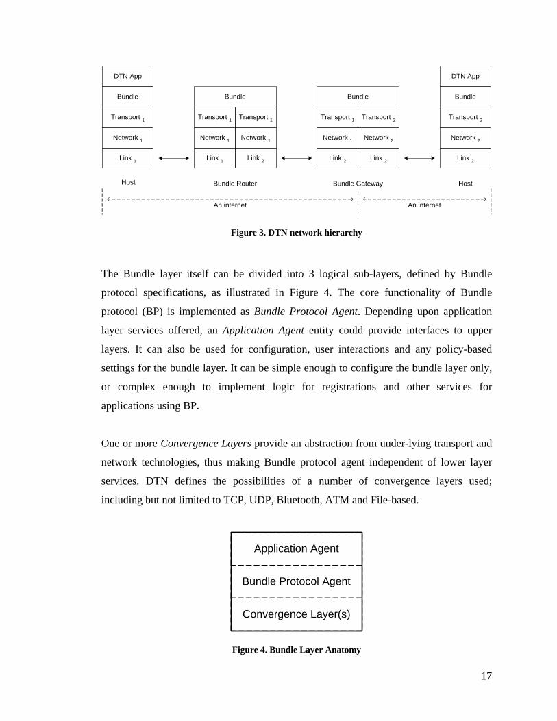
2.2. Network Hierarchy and Protocol Stack
As described earlier in introductory sections, DTN defines an overlay network, which
works on top of transport layers (or equivalent) and below application layer. The
protocol used by DTN nodes is called Bundle protocol, and hence the layer it works at is
termed as bundle layer. The Bundle protocol is layer-agnostic and hence can inter-
connect heterogeneous internets. The nodes that participate in DTN, running bundle
protocol, can be configured in a number of ways including hosts, gateways, routers,
proxies etc. An example topology is described in Figure 3.
16
An internet An internet
Bundle Gateway
Link 2
Network 1
Transport 1
Bundle
Link 2
Network 2
Transport 2
Host
Link 2
Network 2
Transport 2
Bundle
DTN App
Bundle Router
Link 1
Network 1
Transport 1
Bundle
Link 2
Network 1
Transport 1
Host
Link 1
Network 1
Transport 1
Bundle
DTN App
Figure 3. DTN network hierarchy
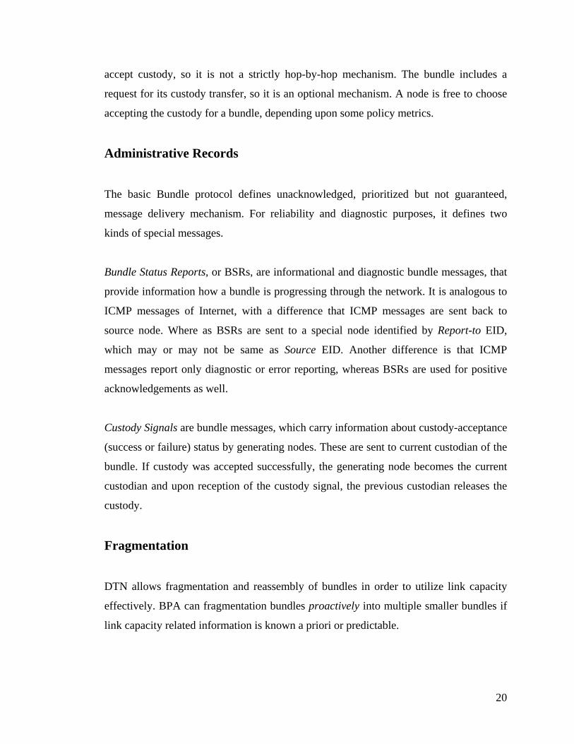
The Bundle layer itself can be divided into 3 logical sub-layers, defined by Bundle
protocol specifications, as illustrated in Figure 4. The core functionality of Bundle
protocol (BP) is implemented as Bundle Protocol Agent. Depending upon application
layer services offered, an Application Agent entity could provide interfaces to upper
layers. It can also be used for configuration, user interactions and any policy-based
settings for the bundle layer. It can be simple enough to configure the bundle layer only,
or complex enough to implement logic for registrations and other services for
applications using BP.
One or more Convergence Layers provide an abstraction from under-lying transport and
network technologies, thus making Bundle protocol agent independent of lower layer
services. DTN defines the possibilities of a number of convergence layers used;
including but not limited to TCP, UDP, Bluetooth, ATM and File-based.
Convergence Layer(s)
Bundle Protocol Agent
Application Agent
Figure 4. Bundle Layer Anatomy
17

2.3. DTN Family of Protocols
The DTN research group has defined a basic bundling protocol. There are other drafts
produced by researchers for convergence layers, routing and security protocols. In the
following sub-section, a general notation and terminology used throughout in those
documents is described. Later on, the semantics of basic protocols are discussed.
2.3.1. Protocol Design Principles
DTN has defined some new general terminologies and concepts used in the design of
DTN family of protocols, which are presented below.
End-point Identifiers
As described earlier, DTN uses a general naming scheme to identify nodes. These names
are called End-point Identifiers or EIDs. EID’s are based on URI schemes with the
syntax:
<scheme name> : <scheme specific part or SSP>
Any of the standard URI schemes can be used and DTN also defines its own scheme,
denoted as “dtn”. A special case is dtn:none. Since DTN employs the concept of late
binding, EIDs are not translated to addresses in the very beginning, in contrast to the
Internet protocols. Instead routing is performed based on EIDs directly.
EIDs are also a unique concept in a way that a node can be member or multiple EIDs and
one EID can be associated with multiple nodes. Thus routing becomes more complex,
and this is an on-going research area. A singleton EID is the one, which is associated
18

with a single node only. Some of the protocol semantics, such as custody transfer, are
only defined for singleton EIDs only. The Bundle protocol specifications state that a
Bundle node must be member of at least one singleton EID.
Bundles
DTN payloads are in the form of messages, formally called Bundles. As explained
earlier, DTN suggests combining all application layer data and associated meta-data into
one message called bundle. Bundles can be of variable sizes.
Custody Transfer
As described above, DTN uses store-and-forward operations, which are different from
conventional store-and-forward mechanism of the Internet. The Internet routers store
packets for a very short interval of time directly proportional to queuing and
transmission delays, and discard them if no route to the destination is available. By
definition, DTN has to keep messages or bundles in queues for longer time. DTN also
strongly suggests keeping queued bundles in some form of persistent storage. This helps
coping hardware failures or device startups.
Since there may not be an end-to-end path in DTN networks, conventional end-to-end
reliability mechanisms like retransmissions cannot work. DTN moves the responsibility
of reliable delivery from source node to other DTN nodes deeper in the network. This is
achieved by moving a copy of message ‘closer’ to destination (in terms of some routing
metric), and termed as custody transfer. Hence, retransmission related responsibilities
move away from source node gradually, breaking the requirement of end-to-end
retransmissions, as done in the Internet.
The node, which currently has the custody of bundle, is called custodian of the bundle.
When a node gains responsibility of retransmissions of bundles, it accepts custody; when
it discharges, it releases custody. Not all the DTN nodes in the network are required to
19
accept custody, so it is not a strictly hop-by-hop mechanism. The bundle includes a
request for its custody transfer, so it is an optional mechanism. A node is free to choose
accepting the custody for a bundle, depending upon some policy metrics.
Administrative Records
The basic Bundle protocol defines unacknowledged, prioritized but not guaranteed,
message delivery mechanism. For reliability and diagnostic purposes, it defines two
kinds of special messages.
Bundle Status Reports, or BSRs, are informational and diagnostic bundle messages, that
provide information how a bundle is progressing through the network. It is analogous to
ICMP messages of Internet, with a difference that ICMP messages are sent back to
source node. Where as BSRs are sent to a special node identified by Report-to EID,
which may or may not be same as Source EID. Another difference is that ICMP
messages report only diagnostic or error reporting, whereas BSRs are used for positive
acknowledgements as well.
Custody Signals are bundle messages, which carry information about custody-acceptance
(success or failure) status by generating nodes. These are sent to current custodian of the
bundle. If custody was accepted successfully, the generating node becomes the current
custodian and upon reception of the custody signal, the previous custodian releases the
custody.
Fragmentation
DTN allows fragmentation and reassembly of bundles in order to utilize link capacity
effectively. BPA can fragmentation bundles proactively into multiple smaller bundles if
link capacity related information is known a priori or predictable.
20

In some cases, if a bundle is partially transmitted to next hop and the two peer nodes
detect this, the transmitting node may reactively fragment the remaining portion into a
new bundle. Similarly, the receiving node may modify the incoming portion of bundle to
make it a fragment. Reactive fragmentation is an optional capability because it depends
upon services offered by underlying convergence layers, whether they provide
mechanism for partial transfers.
Like in IP, fragmentation is done on only one ‘level’, i.e. a bundle is fragmented into two
to make new bundles. If needed, those new bundles can be fragmented further. This
process is loosely analogous to mitosis process of biological cell division, in which a cell
is divided into two. Also like IP, reassembly is performed at destination node only.
Class of Service
DTN defines a coarse-grained postal-style prioritized delivery services. The quality of
service metrics are different from conventional Internet style traffic, as DTN traffic is
generally not interactive, may be one way, and obviously with least timely delivery
requirements. There are 3 priority classes defined in DTN architecture (priority low to
high): Bulk, Normal and Expedited. DTN nodes should transfer bundles with high
priority first. At the moment, there is no well-defined quality of service mechanism in
DTN.
Self Delimiting Numeric Values
DTN specifications define protocol formats in such a way that it can be easily modified
in future. One fundamental concept is how to represent fields that contain numbers
denoting lengths and sizes. DTN defines a new scheme for number representation that is
similar to ASN.1 encoding. This is termed as Self Delimiting Numeric Values or SDNVs,
and as name implies, they can be of variable length. Each byte representing the number
field contains a special marker bit, so that last byte can be detected. Hence with a small
overhead of total marker bits, greater flexibility is achieved. Hence the any arbitrary
21
length of a field can be described without changing the header in future. DTN
architecture recommends using SDNVs in all relevant protocols, which have been or
could be defined. For details see [BPSPEC04].
DTN Time Stamps
DTN also defines a new notation for representing time stamps. Time stamps are 64-bit
fields, with first 32-bits (in network byte order) contain number of seconds elapsed since
start of year 2000. The remaining 32-bits contain number of nanoseconds since start of
current second at the time of creating time stamp. All relevant protocols must use this
notation to describe any time-related information.
2.3.2. Bundle Protocol
The primary DTN protocol running at Bundle layer is called Bundle protocol. Bundle
protocol defines semantics, formats and sequences of protocol messages in order to carry
out basic bundle layer services, including:
Asynchronous message transfer
Generation of Bundle Status Reports messages
Custody transfer related signaling
The Bundle protocol design is based upon the architectural and protocol design
principles described in the earlier sections. It defines a primary bundle message header,
along with a payload header and administrative records’ header formats [BPSPEC04].
The Bundle protocol permits use of additional extension headers specified by
supplementary protocol specification documents. Some important fields of these headers
are described here; for details see [BPSPEC05].
22
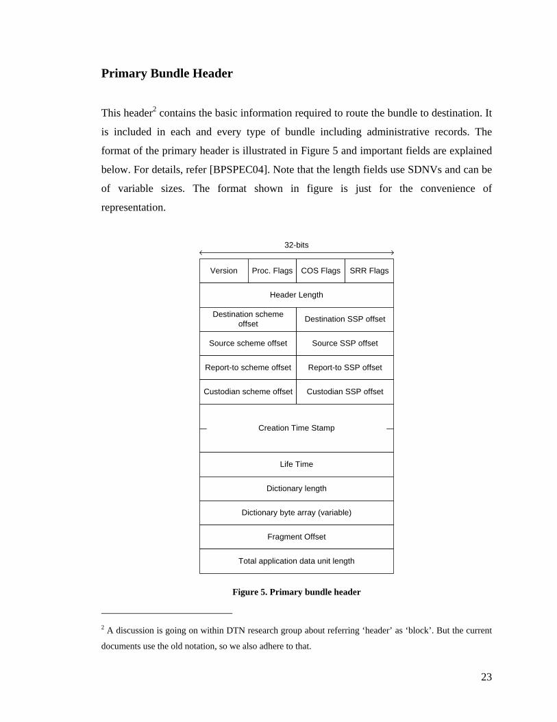
Primary Bundle Header
This header2 contains the basic information required to route the bundle to destination. It
is included in each and every type of bundle including administrative records. The
format of the primary header is illustrated in Figure 5 and important fields are explained
below. For details, refer [BPSPEC04]. Note that the length fields use SDNVs and can be
of variable sizes. The format shown in figure is just for the convenience of
representation.
Version Proc. Flags COS Flags SRR Flags
Header Length
Destination schemeoffset Destination SSP offset
Source scheme offset Source SSP offset
Report-to scheme offset Report-to SSP offset
Custodian scheme offset Custodian SSP offset
Creation Time Stamp
Life Time
Dictionary length
Dictionary byte array (variable)
Fragment Offset
Total application data unit length
32-bits
Figure 5. Primary bundle header
2 A discussion is going on within DTN research group about referring ‘header’ as ‘block’. But the current
documents use the old notation, so we also adhere to that.
23
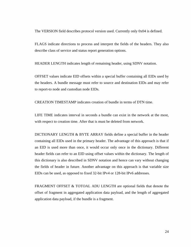
The VERSION field describes protocol version used. Currently only 0x04 is defined.
FLAGS indicate directions to process and interpret the fields of the headers. They also
describe class of service and status report generation options.
HEADER LENGTH indicates length of remaining header, using SDNV notation.
OFFSET values indicate EID offsets within a special buffer containing all EIDs used by
the headers. A bundle message must refer to source and destination EIDs and may refer
to report-to node and custodian node EIDs.
CREATION TIMESTAMP indicates creation of bundle in terms of DTN time.
LIFE TIME indicates interval in seconds a bundle can exist in the network at the most,
with respect to creation time. After that is must be deleted from network.
DICTIONARY LENGTH & BYTE ARRAY fields define a special buffer in the header
containing all EIDs used in the primary header. The advantage of this approach is that if
an EID is used more than once, it would occur only once in the dictionary. Different
header fields can refer to an EID using offset values within the dictionary. The length of
this dictionary is also described in SDNV notation and hence can vary without changing
the fields of header in future. Another advantage on this approach is that variable size
EIDs can be used, as opposed to fixed 32-bit IPv4 or 128-bit IPv6 addresses.
FRAGMENT OFFSET & TOTOAL ADU LENGTH are optional fields that denote the
offset of fragment in aggregated application data payload, and the length of aggregated
application data payload, if the bundle is a fragment.
24

Bundle Payload Header
This simple header describes the type of payload (which is currently always 0x01), flags
indication directions to process the header and a length field in SDNV notation to
describe the length of payload. The format is illustrated in Figure 6. The length fields use
SDNVs and can be of variable sizes. The format shown in figure is just for the
convenience of representation. Additional protocol documents can define more payload
header types such as routing information, security headers. At the moment, payload can
either be application level data or an administrative record header.
Headertype Proc. flags Header Length
Bundle payload (variable)
32-bits
Figure 6. Bundle payload header
Bundle Status Report and Custody Signal Formats
If the primary header’s processing flag indicate that the bundle payload is an
administrative record then the payload is processed according to a specific format. The
first byte describes the type of administrative record (status report or custody signal) and
some optional flags for additional information describing directions to interpret
remaining fields.
If the administrative record is a status report then the remaining fields describe type(s) of
status report and the time when the event took place, for which the report was generated,
in DTN timestamp format. One administrative record message can aggregate multiple
reports for the same bundle, thus reducing network traffic. The format is shown in Figure
25
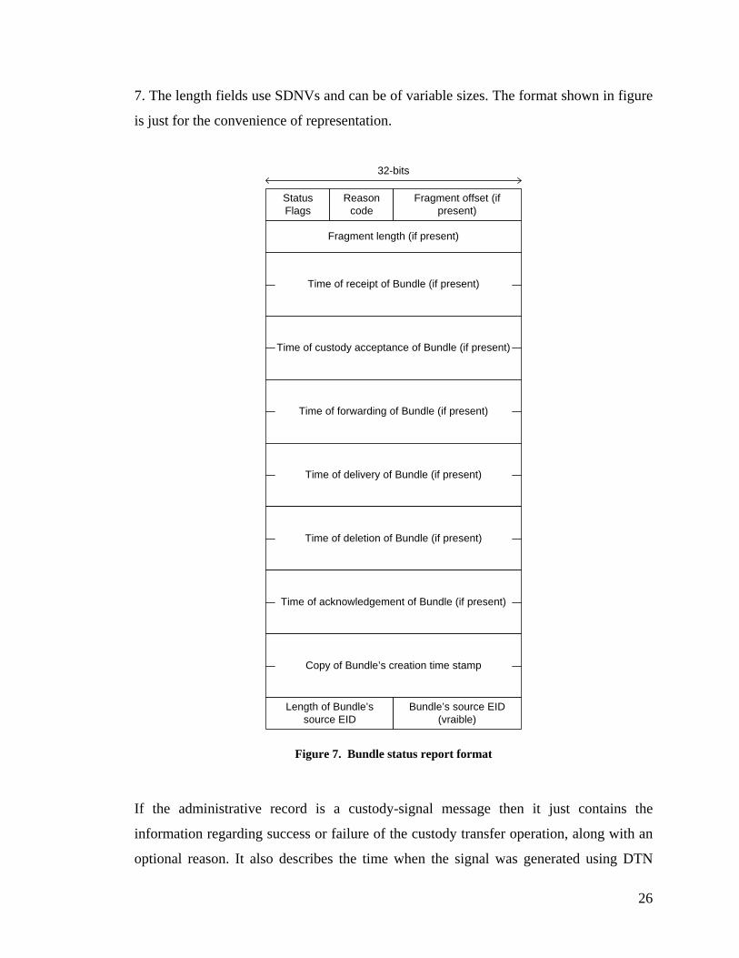
7. The length fields use SDNVs and can be of variable sizes. The format shown in figure
is just for the convenience of representation.
StatusFlags
Reasoncode
Fragment offset (ifpresent)
Fragment length (if present)
Time of receipt of Bundle (if present)
Time of custody acceptance of Bundle (if present)
Time of forwarding of Bundle (if present)
Time of delivery of Bundle (if present)
Time of deletion of Bundle (if present)
Time of acknowledgement of Bundle (if present)
Copy of Bundle’s creation time stamp
Length of Bundle’ssource EID
Bundle’s source EID(vraible)
32-bits
Figure 7. Bundle status report format
If the administrative record is a custody-signal message then it just contains the
information regarding success or failure of the custody transfer operation, along with an
optional reason. It also describes the time when the signal was generated using DTN
26
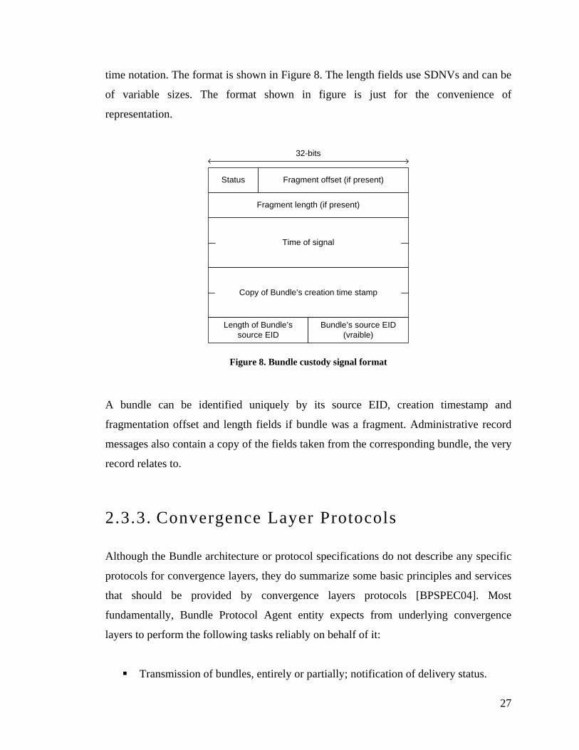
time notation. The format is shown in Figure 8. The length fields use SDNVs and can be
of variable sizes. The format shown in figure is just for the convenience of
representation.
32-bits
Status Fragment offset (if present)
Fragment length (if present)
Time of signal
Copy of Bundle’s creation time stamp
Length of Bundle’ssource EID
Bundle’s source EID(vraible)
Figure 8. Bundle custody signal format
A bundle can be identified uniquely by its source EID, creation timestamp and
fragmentation offset and length fields if bundle was a fragment. Administrative record
messages also contain a copy of the fields taken from the corresponding bundle, the very
record relates to.
2.3.3. Convergence Layer Protocols
Although the Bundle architecture or protocol specifications do not describe any specific
protocols for convergence layers, they do summarize some basic principles and services
that should be provided by convergence layers protocols [BPSPEC04]. Most
fundamentally, Bundle Protocol Agent entity expects from underlying convergence
layers to perform the following tasks reliably on behalf of it:
Transmission of bundles, entirely or partially; notification of delivery status.
27

Reception of bundles, entirely or partially; notification of reception status.
Connection management (establishment, teardown, error detection etc.) specific
to underlying transport technology.
Convergence layer protocol operations can be as simple as connection management and
message boundary marking in case of a reliable underlying transport like TCP. On the
other hand for a connection-less unreliable transport protocol, like UDP, a convergence
layer protocol should implement its own reliable delivery mechanism.
There is an unofficial release of a draft document for TCP (available in the release
package of reference implementation code), which in principle can be use for any
connection-oriented stream protocol. The same protocol has been adapted for Bluetooth
convergence layer.
TCP Convergence Layer Protocol
Since TCP is a connection-oriented reliable transport protocol, this convergence layer
has to perform only two basic tasks:
Marking message boundaries with delimiters, as TCP is stream-oriented protocol,
it does not define and boundaries for application layer data units. So convergence
layer must define its own mechanism to extract segmented or aggregated
messages obtained from the contiguous stream.
Detection of connection and transmission status. Although TCP provides a
reliable delivery mechanism, it does not offer any services for upper layer to
acknowledge delivery of data to the application running on peer node.
Applications using TCP must devise their own mechanism to provide precise
information regarding data delivery, connection teardown etc. Applications are
not precisely notified about TCP connection failures in some scenarios. To cope
such issues, the TCP CLA exchanges application level acknowledgements and
regular keep-alive messages between the peers of a connection.
28
A draft has been proposed describing TCP convergence layer [TCPCL]. It defines TCP
CL level messages with short headers and delimiters to mark message boundaries. In
addition to that, it defines mechanisms for graceful connection establishment and
teardown by sending messages and using timers.
The TCP CL protocol defines a connection to be a unidirectional3 link in terms of data
transfer direction. Since a TCP connection itself is a bi-directional link, TCP CL
protocol level messages can be sent in either direction over same connection. The peer,
which initiates a connection, is termed as ‘connection-initiator’ and is responsible for
deciding direction of connection. A connection-initiator can be a receiver. This helps in
situation when the node is behind a NAT (firewall), so it can establish a connection to
some node outside NAT (firewall). Hence no NAT (firewall) traversal mechanism is
required.
Following is description of basic message formats defined by protocol.
CONTACT HEADER message is sent upon connection establishment, by both the peers.
It contains connection parameters, which define the flow of information over the
connection. After preamble, a 4-byte constant representing ASCII codes of letters in
string “dtn!”, a version field indicates current version of protocol as 2. Flags identify
connection direction and request for application level acknowledgements. An interval, in
seconds, is offered for keep-alive message exchange.
There is a 32-bit number denoting partial acknowledgement length, which enables the
receiver to send regular acknowledgements during the coarse of bundle transmission.
This feature is useful to detect connection drop earlier, and is particularly useful if
bundle is quite large. In case of partial transfer of a bundle, if the connection drops, the
BP layer can fragment the bundle reactively to send remaining portion.
3 This is going to be changed in the near future.
29
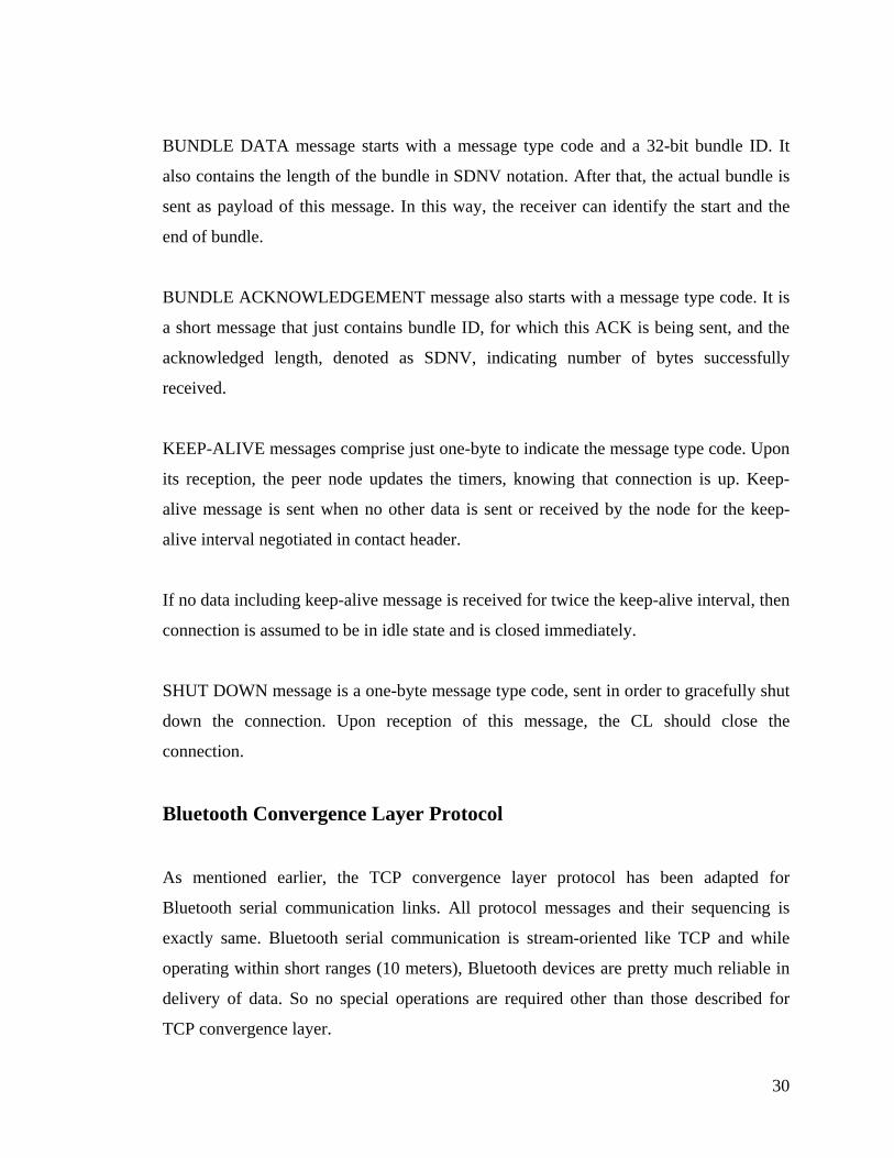
BUNDLE DATA message starts with a message type code and a 32-bit bundle ID. It
also contains the length of the bundle in SDNV notation. After that, the actual bundle is
sent as payload of this message. In this way, the receiver can identify the start and the
end of bundle.
BUNDLE ACKNOWLEDGEMENT message also starts with a message type code. It is
a short message that just contains bundle ID, for which this ACK is being sent, and the
acknowledged length, denoted as SDNV, indicating number of bytes successfully
received.
KEEP-ALIVE messages comprise just one-byte to indicate the message type code. Upon
its reception, the peer node updates the timers, knowing that connection is up. Keep-
alive message is sent when no other data is sent or received by the node for the keep-
alive interval negotiated in contact header.
If no data including keep-alive message is received for twice the keep-alive interval, then
connection is assumed to be in idle state and is closed immediately.
SHUT DOWN message is a one-byte message type code, sent in order to gracefully shut
down the connection. Upon reception of this message, the CL should close the
connection.
Bluetooth Convergence Layer Protocol
As mentioned earlier, the TCP convergence layer protocol has been adapted for
Bluetooth serial communication links. All protocol messages and their sequencing is
exactly same. Bluetooth serial communication is stream-oriented like TCP and while
operating within short ranges (10 meters), Bluetooth devices are pretty much reliable in
delivery of data. So no special operations are required other than those described for
TCP convergence layer.
30

Bluetooth RF serial communication (or serial port profile, SPP, in Bluetooth
terminology) is the basic communication mechanism supported by every Bluetooth
device. A Bluetooth device is assigned a 48-bit unique MAC address, which is used to
identify the device in serial communication, as IP is used in the Internet. Each
application using SPP is identified by a unique channel number (similar to port numbers
in TCP/IP). Bluetooth protocol specifications define an 8-bit channel number ranging
from 0 to 255. Serial communication is also stream oriented. All these similarities with
TCP makes it possible to adapt the TCP CL protocol easily.
2.3.4. Routing Protocols
At the moment, DTN does not define any particular routing protocol to use with the
Bundle protocol. A variety of routing algorithms and protocols can be used, depending
upon DTN application area, from simple epidemic routing to complex statistical and
heuristic algorithms. Nevertheless, researchers have proposed some routing algorithms
and protocols for DTN. A couple of epidemic routing algorithms have been implemented
in the reference implementation and in this thesis work as well. In the following, a brief
description of some routing algorithms and protocols is provided; while there are many
further research efforts, the routing approaches listed below have been implemented for
the DTN reference implementation.
Static Routing
Static routing is the simplest form of routing, in which the routes from source to all
possible destinations are provided statically at system startup. Usually, the routing
information does not change, or new routes may be added manually. Hence no protocol
is required for routing information propagation.
31

Flooding
Flooding is another simple routing algorithm, in which the incoming data is transmitted
to all the links except from which the data arrived. Flooding also does not require any
protocol for routing information propagation. Nevertheless, some mechanism is required
to prevent loops, so that source node should not keep on forwarding same data over and
again. One simplest mechanism is to keep hop count, and discarding data using some
threshold value. Another mechanism is to keep track of transmitted data using some
unique identifier. If the same data arrives again, it can be discarded.
PRoPHET
A probabilistic algorithm PRoPHET (Probabilistic Routing Protocol using History of
Encounters and Transitivity) has been recently proposed for DTN. It exploits the
mobility patterns followed by users carrying mobile devices, which may form an ad hoc
network. Normally, a random movement of nodes is assumed in an ad hoc network. But
users in daily life follow a fixed pattern repetitively. PRoPHET discusses mechanism to
keep track of this pattern and use these metrics for deciding the routes. The details are
provided in [LIND06].
2.3.5. Neighbor Discovery
One of the largest application areas of DTN is the MANETs with intermittent
connectivity, having no end-to-end path available most of the time. The nodes
participating in the mobile ad hoc network may not have time or means to configure
network parameters, particularly if the connectivity interval is quite short. Examples are
ad hoc networks formed in a market or at a disastrous place or on board in a public
transport vehicle. In order to achieve effective communication, the nodes should be able
discover each other and establish a network automatically on the fly. Some routing
protocols for ad hoc networks, such as PRoPHET, also depend upon such mechanism
32
provided by underlying layers. We propose a mechanism for neighbor discovery in
Bluetooth based Ad Hoc networks.
Bluetooth family of protocols specifies a mechanism to advertise the device information,
application services and parameters for the services. Bluetooth devices can query each
other for such information in order to establish a connection. This mechanism is called
Service Discovery Protocol (SDP) and is built into the Bluetooth protocol stack. SDP
works at L2CAP layer and uses a predefined reserved channel. The advertising device
maintains a service database and each service is identified by a universally unique
identifier (UUID). Upon request from another Bluetooth device, the service information
is sent to it. In this way, a device can determine what applications are supported by the
others and how those devices can be connected to [BRAY].
We have used SDP to advertise the device MAC address and channel identifier for SPP
using RFComm service UUID. This information has been termed DTN-service. The
Bluetooth convergence layer in our implementation advertises its DTN-service
information and discovers other devices in neighborhood advertising their DTN-service
information. The implementation details are provided in Chapter 5.
2.4. Summary
In this chapter, DTN architecture has been explained. It also included an overview of
DTN family of protocols, mainly he Bundle protocol and convergence layer protocols. A
few experimental routing protocols have been discussed briefly. Finally a neighbor
discovery mechanism for Bluetooth convergence layer has been proposed. Next chapter
describes implementation architecture for DTN, tailored for Symbain based smart
phones.
33

3. IMPLEMENTATION ARCHITECTURE
This chapter describes the top-level architecture of Bundle protocol implem
Symbian mobile phones. Although the overall design is tailored for Symb
level architecture is generic enough to be used on other platforms. This cha
give any detailed design or algorithms, rather describes architectural desi
used in the implementation.
3.1. Conceptual Model of Bundle N
A Bundle node is a logical entity on a DTN node, which implements the Bun
to send and receive bundles. It can be a thread, or process running on gen
computer, or dedicated hardware device. As described in Chapter 2, the Bun
works above the transport layer and below the application layer. Hence it u
offered by transport layer and offers Bundle layer services to applications,
communicate over DTN. Bundle protocol specifications subdivide Bundle
logical sub-layers, as illustrated in Figure 4.
entation for
ian OS, top-
pter does not
gn decisions
ode
dle protocol
eral-purpose
dle protocol
ses services
which could
layer into 3
34

3.1.1. Bundle Protocol Agent
The core protocol logic is handled by the Bundle Protocol Agent. BPA is responsible for
generating and receiving bundles and administrative records. It may also maintain
persistent storage. Besides, BPA is responsible for all routing decisions.
3.1.2. Convergence Layers
To use transport layer services from an abstract level, BPA utilizes one or more
convergence layers. Each convergence layer is optimized for a different transport layer –
but should offer BPA a uniform Service Access Point at an abstract level.
3.1.3. Application Agent
To offer its services to application layer programs, BPA utilizes Application Agent sub-
layer. Depending upon targeted DTN applications, AA should be customized in order to
hand over application layer data and meta-data to BPA. AA may also maintain DTN
applications’ registration information. Registration is a mechanism used by an
application-layer program to identify itself as DTN user-application. It is analogous to
‘handle’ abstraction used in many OS services like file, networking, graphics etc. Each
application using such services is assigned a unique handle, which is used as a reference
to invoke system calls for those services. DTN expands this concept to a more abstract
level and in slightly loosely-coupled fashion. An application may remain ‘registered’ for
a DTN service even if the program is not running. DTN defines active and passive
registration states for this purpose.
35

DTN Applications
DTN applications are application layer programs using Bundle node in order to
communicate in delay-tolerant networks. Since DTN uses a different concept of network
communication, applications may need to be tailored accordingly. For example,
conventional FTP cannot be used as it is in DTN networks. So either FTP client
applications can be altered to provide all data and/or meta-data at once to Bundle
protocol, or some gatewayapplication can be designed to bridge between conventional
applications and Bundle node.
3.2. Architecture for Symbian OS
Although the top-level architecture is quite generic, it mainly targets Symbian OS.
Symbian OS programming issues are discussed in detail in next chapter. Nevertheless
some general features are described here, before discussing the top-level design.
3.2.1. Symbian OS
Symbian OS is the dominant OS for smart phones and other handheld devices like PDAs
[SYMB]. Such devices have constrained resources; battery-power, memory, processing
capabilities etc. Yet they are becoming widely used devices, carried by users most of the
time, to most of the places they visit. This makes smart-phones based inter-personal
communication an interesting and potential application platform for DTN.
Owing to be running on devices with constrained resources, Symbian OS introduces may
architectural and system design concepts, which are different form other operating
systems running on general purpose computers. It offers OS-level services
asynchronously, and provides a rich library of utility functions, algorithms and data-
structures especially optimized for constrained-devices. To execute asynchronous tasks,
36

Symbian OS defines its own mechanism of multitasking (explained in next chapter).
Symbian OS also defines a unique IPC mechanism, which is used by OS services as
well.
3.2.2. Top-level Architecture
The top-level architecture of bundle-node application follows the conceptual model
described in earlier sections of this chapter. The software comprises 3 main components:
BPA, AA and CLA(s). For modularity, these components are subdivided into logical
blocks. This is illustrated in Figure 9. BPA component implements the core logic of
Bundle protocol. It utilizes a Router component to make routing decisions. At the
moment, Router component obtains routing information from a file, because at the
moment, Bundle protocol does not define any semantics for route information
propagation. Router component can be expanded to determine routes on its own, as it
executes asynchronously. Alternatively, BPA can also update its routing information.
BPA
CLA 1 CLA n
Router
UI & Config.
AA
App 1 App m
Figure 9. Top-level Architecture
37
BPA can utilize one or more Convergence Layer Adapters in order to use underlying
transport layer services. CLA components provide a generic API as Service Access
Points. Currently, two convergence layers are supported in the design: TCP CL for
TCP/IP and Bluetooth CL for serial communications. BPA can launch either or both of
these upon user request.
Application Agent provides a SAP to DTN applications (referred as App in above figure)
wishing to utilize BPA services that can be access through Symbian OS IPC mechanism.
DTN applications can register with the AA, which presents bundle transmission requests
to BPA on behalf of DTN applications. IPC mechanism enables multiple DTN
applications to utilize BP services, asynchronously. This enhances modularity and new
DTN applications can be developed without modifying BP application.
User-Interface component is mainly used to configure the application while it is
executing. The user can configure different options for BPA, start CLA services and
enable/disable logging information etc. It provides a graphical user interface for this
purpose, in the form of menus and dialog boxes etc. Another use of UI component is to
invoke BPA services locally, without needing any external DTN application. This
functionality is useful for demonstration and diagnostic purposes. User can send any
media file to other mobile-phone using Bundle protocol, which is received and saved by
BP application on that device.
In the following we discuss some fundamental architectural concepts used in the
implementation.
Asynchronous Interaction via Message Queues
The layered architecture of application requires that components should not use
synchronous or blocking operations, which could take significant processing time. This
would degrade the performance; for example if application is listening for a connection
synchronously, it will not be able to perform any other tasks. Hence the different
38

components of application interact asynchronously. Symbian OS applications utilize a
concept similar to threads for multitasking and asynchronous operations, explained in
next chapter.
Components require some mechanism in order to exchange data and use services offered
by other components, asynchronously. A notion of ‘message queues’ is used for this
purpose. Every component owns two queues to store data, operational instructions and
status. One queue holds requests for the services offered by the component, termed as
TxQ. The other queue holds replies (results and status) for those requests, termed as
RxQ. In order to relate requests and replies in two queues, an identifier is used. The
queues operate as a FIFO; first-in, first-out queues.
IPC based API
Application Agent offers Bundle protocol services to DTN application via a generic API,
which is based upon Symbian OS native Inter-Process Communication. Bundle node
executes as server applications. DTN applications connect to Bundle node as client
application. This process may include registration, implicitly or explicitly. DTN
applications then can use Bundle protocol services to send or receive data.
User Interface Design Issues
Different Symbian devices may vary in user interface styles. This is the reason why
Symbian OS variants offer a common base for basic OS services, but can use slightly
varying API for user interface designs. The application is designed in such a way that
decouples UI component from other components. Hence a customized version of UI
components can be implemented for each variant of Symbian OS, while the core
components of Bundle protocol are reused without modification.
39

3.3. Summary
This chapter described a generic software architecture for the Bundle node
implementation, tailored for Symbian OS. The architecture is decomposed into several
components, while preserving the protocol hierarchy as described in the specification
documents. Next chapter provides a crash course for Symbain OS application design,
before each component is described in detail.
40

4. PROGRAMMING FOR SYMBIAN OS AND DESIGN PATTERNS
This chapter describes some of unique aspects of Symbian OS programm
This chapter also discusses some design patterns used by Symbian ap
general or specifically by this implementation of the Bundle protocol.
4.1. Programming for Symbian OS
As mentioned in the previous chapter, Symbian OS was specifically design
held devices (such as mobile phones, PDAs) with constrained resources
memory, battery power, processing capabilities). Symbian OS has been
C++ programming language, hence C++ being native programming langu
also supports other programming languages such as Java, Python with th
virtual machines, interpreters etc. Since this application developed in the
ing in detail.
plications in
ed for hand-
(screen size,
developed in
age for it. It
e support of
thesis work
41

functions as a server program, it has been implemented using C++ for better
performance in terms of code optimization and speed of execution.
Although Symbian OS uses C++, which is a standardized, widely used and well matured
programming language, the roots of Symbian OS dates back to mid 90s when C++ was
still going through standardization process. Hence some of the advanced features of
OOP languages were not supported by compilers at that time. Symbian OS introduced its
own mechanism similar to concepts found in modern OOP languages today. For
example, exception handling is not supported by Symbian OS; nevertheless Symbian OS
uses its own mechanism to achieve similar behavior.
Symbian OS also does not use standard library functions and data-structures used by
C++ programmers, such as Standard Template Library (STL), IOStream, file-handling.
These library functions and data-structures require significant memory space for code
and data, making them infeasible for hand-held devices with limited memory. Symbian
OS provides its own library functions and data-structures to serve these purposes.
Symbian OS provides an API for a wide range of library and utility functions such as file
handling, graphics, communication and networking, inter-process communication, string
handling and processing. Some of unique features of Symbian OS, which govern the
application design considerations, are discussed below.
4.1.1. Code Optimization
As mentioned earlier, Symbian OS provides a wide range of library functions. Since
hand-held devices have limited permanent storage and physical memory for code
execution, these library functions are specifically optimized for hand-held devices in
terms of code size and execution speed. The OS code itself, along with library functions,
is placed in ROM in the form of DLLs. Applications programs are also stored as DLLs
in the Flash memory. These DLLs contain only executable code and read-only data.
42

When an application executes, only one copy is loaded in the RAM, which is shared by
all the instances of the programs using it. The OS code and library functions do not need
to be fetched into RAM for execution; rather they are directly accessed and executed
from ROM. RAM only holds application program DLLs, stack and the heap. This is
termed as in-place execution.
4.1.2. Clean-up Stack & Leave Mechanism
Since memory is an expensive resource in Symbian OS devices, loosing memory
chunks, due to memory-leaks in programs is not affordable. Memory is leaked when it is
allocated dynamically and then not destroyed properly, after use. When a dynamically
allocated memory is freed, it goes back to heap; in case of a memory-leak, it does not.
Hence the application would run short of heap memory and program execution would
cease or crash. Unfortunately, C++ does not offer any neat and clean mechanism for
handling memory-leaks gracefully, like garbage collector used in Java. Symbian OS
defines a similar mechanism via clean-up stack and function leave mechanism. Function
leaving is similar to exceptions found in OOP languages.
A function leaves (i.e. returns) abnormally if any exception occurs due to some
erroneous condition like resource unavailability. Many of the API functions offered by
Symbian OS can leave. If a function leaves, dynamically allocated memory by that
function would be leaked, as all the references available for that would be lost. Since
exception can occur at any stage in function execution, it is necessary to keep track of all
the memory dynamically allocated, so that it could be deleted when function leaves.
Symbian OS provides a neat mechanism for this purpose. A reference of each object,
dynamically created, is pushed to a clean-up stack provided by the framework. Hence if
a function leaves, framework pops all the references previously pushed onto it and
destroys the memory. Hence clean-up stack, together with the leave mechanism, co-
serves as garbage collector and exception handling mechanism. Nevertheless, unlike
garbage collector used in Java, this mechanism does not work always automatically. The
43

programmer has to explicitly call the API functions to destroy objects from the cleanup
stack in normal cases. Nevertheless, the objects are deleted automatically if an exception
occurs and the function leaves abnormally.
4.1.3. Thin Templates
Templates are often used in C++ to provide blueprints of algorithms for data structures.
Hence the algorithms can be reused for any data type without recoding. Compilers
automatically generate code for template classes. In some cases, it results in a separate
copy generated for each version, hence increasing code size significantly. Symbian OS
uses a concept called thin-templates to keep its code size smaller. The basic idea is to
separate the code, which uses template references from other code, by breaking it into
small functions. Hence a very small portion of code is replicated for each template class.
This reduces OS code size. All the collection classes (queues, arrays etc.) of Symbian
OS use thin-templates.
4.1.4. Active Objects
Symbian OS discourages the use of threads for performance reasons. Threads require
context-switching mechanism, which is an overhead for system resources: memory and
CPU time. Moreover, multi-threaded applications require some kind of intra-process
synchronization mechanism via mutexes or semaphores. This also requires extra coding.
Nevertheless multitasking is necessary for sophisticated applications to perform
background tasks and asynchronous operations. Symbian OS introduces co-operative
multitasking in contrast with preemptive multitasking used in conventional operating
systems using threads as basic execution unit. In co-operative multitasking, each
execution unit performs a small operation and then gives chance to others for completing
their operations; hence termed co-operative. OS does not preempt the execution before
completion. Hence no mechanism for intra-process synchronization is required.
44
Symbian programs achieve this by using active objects. Classes, which perform
asynchronous or background tasks, are derived from active-object class. The framework
creates an active scheduler for each process. When a function is called which requires
asynchronous execution, active scheduler is signaled. The Active Object class provides a
callback function, which is called by framework when associated asynchronous task is
completed. Each active object is allowed to have only one request pending for
asynchronous operation. While the requested asynchronous operation is being executed
in the background, the active object stops further execution, giving chance to the other
active objects to perform their operations.
4.1.5. Naming Conventions
In order to better utilize resources, Symbian divides classes into four types. T-classes
objects are of small size and can be created on stack; hence can be used as automatic
variables. M-classes encapsulate abstract classes, which define interfaces. Objects of
such classes cannot be instantiated, and these classes are only used to derive from them.
C-classes contain member objects, which are too large to be created on stack. Hence
such objects are created on heap, and their reference is placed on clean-up stack. R-
classes contain handles, which are references to other services offered by operating
system servers or application servers. These letters are prefixed in the names of classes.
Leaving function names are appended by letter ‘L’ to denote that this function can leave.
A function calling other leaving functions is also a leaving function. In order to break the
nesting, a function, which calls other leaving functions, can place a trap harness by
using a macro. The leaving process stops at the first occurrence of the trap harness.
4.1.6. Strings and Binary Data
Symbian OS does not supports conventional C-style char-pointer based strings and STL-
strings are not available either, in library functions. Symbian OS provides thin-template
45
based wrappers for single-byte data types. Strings are special case of binary data. This
mechanism also provides an abstract interface for Unicode character set which requires
two bytes per character. These data types in Symbian are called descriptors.
4.1.7. Client-Server Framework
Symbian OS offers its services via special programs executed by the kernel. These
programs are called system servers. Symbian OS provides a generic IPC API to use these
services. Some examples are file server, serial communication server, socket server, and
window server. User-level programs can also offer their services utilizing the same IPC
mechanism; hence termed as application servers.
4.2. Design Patterns
Design patterns are algorithmic solutions to commonly occurring problems in software
engineering. They speed up the design process by providing an efficient, documented
and tested algorithm for the problem. Like other OOP languages and systems, Symbian
OS also utilizes many design patterns, both in framework and in application design. A
couple of design patterns, which are used in the implementation of Bundle node, are
briefly described in the following.
4.2.1. Model-View-Controller Pattern
MVC pattern describes a software architecture that splits an application’s data, view and
control logic into three components i.e. model, view and controller respectively. As a
result of this decoupling, modifications of any of the components have minimal effect on
other components. This pattern is used by many toolkits for GUI based applications like
Symbian, MFC, and QT etc. In Symbian, the basic GUI application framework follows
this pattern. Model holds the data and algorithms to process the data. View component is
46

responsible for drawing the data on screen. The controller logic handles user interactions
and decides how to manipulate the model. This is illustrated in Figure 10.
Model View
Controller
Figure 10. MVC pattern
In Bundle node, BPA, AA, CLAs, all components form model. View and controller are
placed in UI component.
4.2.2. Observer Pattern
Observer pattern is used often in event driven programming. This pattern defines two
components: subject and observer or listener. A subject component generates an event
and then observer is notified via a callback function. This is illustrated in Figure 11.
+Notify()Observer
+NotifyObserver()Subject
+Notify()ObserverA
Figure 11. Observer pattern
47

In Bundle node, all components forming a ‘model’ mimic multitasking via use of
periodic timer events. Each component is associated with a timer active object, which
generates periodic tick events as a subject. The component itself is derived from an
abstract observer class, which provides a virtual function as a callback. On each tick of
timer, the component performs operations on the data in the message queues.
4.3. Summary
This chapter presented an overview of Symbian OS programming and application design
considerations. Symbian OS applications use many design patterns, not so common in
other platforms such as Windows and Unix. Next chapter describes the details of
software components and the use of design patterns described in this chapter.
48

5. DESIGN AND IMPLEMENTATION DETAILS
This chapter describes detailed design of the Bundle node’s implementa
details include breakdown of components into classes, interaction and rela
the classes, and brief description of functionality of each class. Each comp
software is discussed in separate sections, using a bottom-up approach. Syst
built-in classes are beyond the scope of the document.
5.1. Utility Classes
Utility classes implement some general algorithms or data-structures us
classes belonging to different components of the Bundle node.
5.1.1. FNV Hash
tion. Design
tion between
onent of the
em APIs and
ed by other
49

FNV-hash is a simple yet efficient public-domain algorithm for computing smaller (32
or 64 bit) hash values with low collision rate. They are used in several software systems
to compute table indexes, unique identifiers and for similar purposes [FNV].
FNV hash is used to compute unique bundle IDs. A bundle is uniquely identified by its
creation timestamp, source EID and, if applicable, fragmentation length and offset
values. Nevertheless this information cannot be used as such for indexing purposes.
Moreover, TCP CL uses a 32-bit bundle ID while transmitting bundle over the network.
To maintain uniqueness of these values within the network, a 32-bit hash is computed
from the creation timestamp, the source EID and the fragment offset and length fields of
a bundle. This hash value is termed as Bundle ID and can be used for indexing purposes
as well.
FNV Hash Algorithm
FNV hash algorithm, described below, is encapsulated in a class, and can be accessed
via a static function.
Initialize 32-bit hash value with a number proposed in algorithm.
For each byte in data buffer, do the following:
o Take XOr of current data-byte and least-significant byte of hash value.
o Multiply hash value with 32-bit prime number proposed in the algorithm,
using modulo-32 operations.
Final value is the hash value.
5.1.2. EID
This class manipulates end-point IDs and offers following services via member
functions:
50
Parsing of URIs into scheme and scheme-specific parts. The EID is stored in the
member variables in this decomposed form and can be accessed individually.
Composing the scheme and SSP back to complete URI.
Comparing the EIDs.
Cloning of an EID into a new copy.
The EID class also stores an application tag field. This field is used by the AA to
demultiplex incoming data units to the DTN applications. Such mechanism is not
specified by the protocol specification documents, and at the moment, is implementation
dependent. Since EID can be based on any URI scheme, the manner, in which
application tag filed is extracted, is URI and implementation specific. For “dtn” URI
scheme, we propose that application tag should be identified by the last ‘/’ occurring in
the SSP. Hence the format of SSP becomes:
<Bundle node identifier>/<application tag>
Any string after the ‘/’ denotes the application tag, which is stored in the EID class and is
used by the AA for demultiplexing to the corresponding DTN application.
5.1.3. SDNV
This class encapsulates the SDNVs and can perform the following operations:
Parsing of an SDNV string to extract the numeric value. The current
implementation of the algorithm supports extraction of numbers up to 32 bits in
size.
Generating SDNV string from 32-bit numeric value.
Computing the length of SDNV string from numeric value.
51

SDNV String Parsing
SDNV class maintains an array of bytes. It extracts bytes from an SDNV string until last
byte (with the most-significant bit set to 0) is found, and stores into array. Then it
computes the numeric value using the following algorithm.
Initialize 32-bit numeric value with 0.
Set shifting-index to 0;
Starting from last byte in array till first byte in array, do the following in each
iteration:
o Set most-significant bit of current byte to 0, as it is just marker bit.
o Shift left, the bits of the value obtained in previous step, shifting-index
times.
o Add the value obtained in previous step to numeric value.
o Increment shifting-index by 7.
Numeric value placeholder contains SDNV encoded value.
Calculating Length of SDNV String
This algorithm computes the number of bytes a numeric value possesses when encoded
into SDNV string.
Determine minimum number x > 0, such that 2x is greater than the numeric value.
Multiply the value obtained in previous step with 9; divide by 8; ceil the result to
nearest integer.
Divide the result obtained in previous step by 8; ceil the result to nearest integer.
The resultant value is the length of SDNV string in bytes.
Composing SDNV String
The following algorithm describes how to encode a number into SDNV string:
52

Calculate the length of SDNV string from numeric value using the algorithm
above. Generate a byte array of that much length.
Starting from last index of array till first index, repeat the following:
o Store least significant byte into array at corresponding index.
o Set most significant bit of stored byte to 1, except for last iteration. For
last iteration, set this bit to 0.
o Shift number to right 7 bits.
The byte array holds SDNV string.
5.1.4. Schedular-Timer
This class is derived from CTimer, which is provided by Symbian OS. CTimer is an
active-object and encapsulates a timer object, which can be set to generate an event after
certain amount of time. Schedular-Timer class uses Observer pattern. This class
implements virtual callback function RunL, called every time the event is generated. This
function sets timer to fire again, and calls the notify function of the listener object.
Hence the listener object will be notified periodically in order to execute its services.
After experimenting with different variations of the timer value, a value of 100
microseconds has been chosen in order to ensure good responsiveness of the software.
5.1.5. Event-Notifier
This is an interface or abstract base class for observer or listener classes using observer
pattern. It declares a virtual function EventHandler only, used as callback function by
subject class.
53

5.2. Convergence-Layer Adapter Classes
The classes used by convergence layers are described in this section. There are two main
sub-groups of these classes.
5.2.1. Connection Classes
Connection classes encapsulate the basic socket operations for connection opening,
closing, reading and writing data. Symbian sockets perform these services
asynchronously; hence a connection class has to be an Active Object. Connection classes
are derived from an abstract base class. Two derived classes are used in this
implementation: one for TCP connection and the other for Bluetooth RF Comm.
Connections. This hierarchy is shown in Figure 12.
CActive
CConnection
CTCPConnection CBTRFCommConnection
Figure 12. Connection classes
Since a connection class performs its services asynchronously, there is a message
queuing mechanism as described in Chapter 3, implemented in the base class
CConnection. A connection object retrieves command messages for data transmission,
connection opening or closing etc., from its TxQ. It places the status of these requests or
data received in its RxQ. The entity, which owns a connection object, can use Push() and
Pop() functions in order to handover and retrieve data, respectively.
54

Since an Active Object can have only one asynchronous operation pending, Connection
classes implement a state machine to save the state of current operation. Once the current
operation is completed, the framework calls the callback function. In the callback
function, a request for next operation is placed and the state is changed accordingly.
A connection is a bi-directional link, so it is used for both sending and receiving. Since a
connection object can perform only one operation at a time, it switches the roles of
sending and receiving alternatively in order to maintain a fair behavior.
Since a Connection class offers its services to a CLA class asynchronously, the latter
does not know about connection or transmission failures until it reads the status message
from Connection’s RxQ. This can lead to synchronization problems; e.g. a Connection
object is in closed state but the CLA, still being unaware of that, hands over more data to
transmit. To avoid such issues, the CLA always checks the state of Connection object,
and does not handover any data to it if the later is in closed state.
Even though a connection is closed, the CLA does not delete the Connection object until
it retrieves all the status messages from Connection’s RxQ. A connection’s TxQ is
always emptied by itself when it goes to closed state, and a failure status is placed in its
RxQ message for each transmit request.
5.2.2. CLA Classes
These classes implement the convergence layer protocols. A CLA class maintains an
array of Connection-Info objects, which encapsulate a Connection object, and some
other information related to that connection such as connection state, direction, a
temporary buffer for segmentation and reassembly. The relationship between these
classes is shown in Figure 13.
55
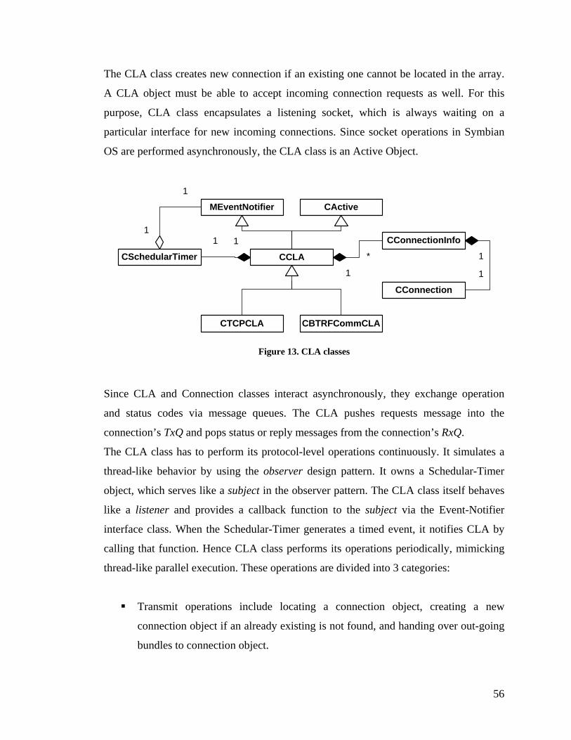
The CLA class creates new connection if an existing one cannot be located in the array.
A CLA object must be able to accept incoming connection requests as well. For this
purpose, CLA class encapsulates a listening socket, which is always waiting on a
particular interface for new incoming connections. Since socket operations in Symbian
OS are performed asynchronously, the CLA class is an Active Object.
CActive
CCLA
CTCPCLA CBTRFCommCLA
MEventNotifier
CConnectionInfo
1
*
CConnection
1
1
CSchedularTimer11
1
1
Figure 13. CLA classes
Since CLA and Connection classes interact asynchronously, they exchange operation
and status codes via message queues. The CLA pushes requests message into the
connection’s TxQ and pops status or reply messages from the connection’s RxQ.
The CLA class has to perform its protocol-level operations continuously. It simulates a
thread-like behavior by using the observer design pattern. It owns a Schedular-Timer
object, which serves like a subject in the observer pattern. The CLA class itself behaves
like a listener and provides a callback function to the subject via the Event-Notifier
interface class. When the Schedular-Timer generates a timed event, it notifies CLA by
calling that function. Hence CLA class performs its operations periodically, mimicking
thread-like parallel execution. These operations are divided into 3 categories:
Transmit operations include locating a connection object, creating a new
connection object if an already existing is not found, and handing over out-going
bundles to connection object.
56
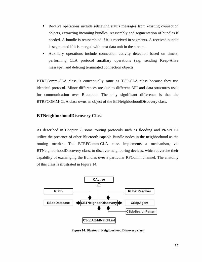
Receive operations include retrieving status messages from existing connection
objects, extracting incoming bundles, reassembly and segmentation of bundles if
needed. A bundle is reassembled if it is received in segments. A received bundle
is segmented if it is merged with next data unit in the stream.
Auxiliary operations include connection activity detection based on timers,
performing CLA protocol auxiliary operations (e.g. sending Keep-Alive
message), and deleting terminated connection objects.
BTRFComm-CLA class is conceptually same as TCP-CLA class because they use
identical protocol. Minor differences are due to different API and data-structures used
for communication over Bluetooth. The only significant difference is that the
BTRFCOMM-CLA class owns an object of the BTNeighborhoodDiscovery class.
BTNeighborhoodDiscovery Class
As described in Chapter 2, some routing protocols such as flooding and PRoPHET
utilize the presence of other Bluetooth capable Bundle nodes in the neighborhood as the
routing metrics. The BTRFComm-CLA class implements a mechanism, via
BTNeighborhoodDiscovery class, to discover neighboring devices, which advertise their
capability of exchanging the Bundles over a particular RFComm channel. The anatomy
of this class is illustrated in Figure 14.
CBTNeighborDiscovery
CActive
RHostResolverRSdp
RSdpDatabase CSdpAgent
CSdpSearchPattern
CSdpAttrIdMatchList
Figure 14. Bluetooth Neighborhood Discovery class
57

This class performs two main tasks: service advertisement and discovery. It starts
advertising the RFComm channel for the Bundle node when the BTRFComm-CLA is
enabled and stops the advertisement when the BTRFComm-CLA is disabled. The SDP
record, which comprises the UUID of the service, channel ID and a textual description of
the service, is added into the SDP database of the device when the service advertisement
is started, and is removed when the advertisement is stopped. This mechanism is
achieved via RSDP and RSDPDatabase classes provided by the framework.
Secondly, this class is responsible for discovering the neighbors and their DTN-service
information continuously on regular basis. This task involves two operations: device
discovery (for the device address) and service discovery (for the channel ID). It
discovers the Bluetooth device addresses of the neighboring Bundle nodes via
RHostResolver class. Then it enquires to all the devices, discovered in this way, about
their SDP records using the CsdpAgent class. The CsdpSearchPattern class is used to
narrow down the search criteria to DTN-service information records only, which uses
the corresponding service UUID to filter out irrelevant service records thus saving
computing resources. The service discovery tasks are performed in the background using
the Active Object design pattern.
When a DTN-capable device is discovered in the neighborhood, the information
retrieved is sent to the BP-Router component by the BTRFComm-CLA class. The BP-
Router component may utilize this information for computing routes by using algorithms
such as flooding or PRoPHET. The BTNeighborhoodDiscovery class maintains a local
cache for the devices discovered so far. The service discovery operation is performed
only for new entries in the cache. Old entries, which cannot be detected in the
neighborhood anymore, are removed from the cache and the BP-Router is also notified
so that it can also remove the corresponding entry from its routing records.
58

5.3. Bundle Protocol Agent Classes
The BPA component implements the core logic of the Bundle protocol; so it uses all the
classes described earlier, directly or indirectly, as shown in Figure 15. In order to
perform protocol level operations, it uses the observer pattern via the Schedular-Timer
and the Event-Notifier classes, similar to the CLA component. The other classes are
described below in detail.
CBase
CBPA
MEventNotifier
CSchedularTimer
11
1
1
CBPRecord
1 *
CBundle
CEIDLookUpRecord
1*
11
11
CCLA
CAdminRecord
10..1
CBPRouter
11
Figure 15. BPA classes
5.3.1. BPA Class
This is the main class of the BPA component and contains the protocol state-machine
logic. It also creates and owns CLA objects, a BP-Router object and maintains a list of
bundles for transmission and reception. This class also provides an interface for the AA
component via message queues, TxQ, RxQ. Since it does not perform any asynchronous
operation locally, rather calls asynchronous services of other components, this class
59
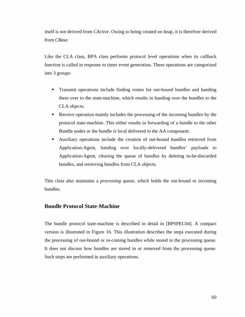
itself is not derived from CActive. Owing to being created on heap, it is therefore derived
from CBase.
Like the CLA class, BPA class performs protocol level operations when its callback
function is called in response to timer event generation. These operations are categorized
into 3 groups:
Transmit operations include finding routes for out-bound bundles and handing
them over to the state-machine, which results in handing over the bundles to the
CLA objects.
Receive operation mainly includes the processing of the incoming bundles by the
protocol state-machine. This either results in forwarding of a bundle to the other
Bundle nodes or the bundle is local delivered to the AA component.
Auxiliary operations include the creation of out-bound bundles retrieved from
Application-Agent, handing over locally-delivered bundles’ payloads to
Application-Agent, clearing the queue of bundles by deleting to-be-discarded
bundles, and retrieving bundles from CLA objects.
This class also maintains a processing queue, which holds the out-bound or incoming
bundles.
Bundle Protocol State-Machine
The bundle protocol state-machine is described in detail in [BPSPEC04]. A compact
version is illustrated in Figure 16. This illustration describes the steps executed during
the processing of out-bound or in-coming bundles while stored in the processing queue.
It does not discuss how bundles are stored in or removed from the processing queue.
Such steps are performed in auxiliary operations.
60
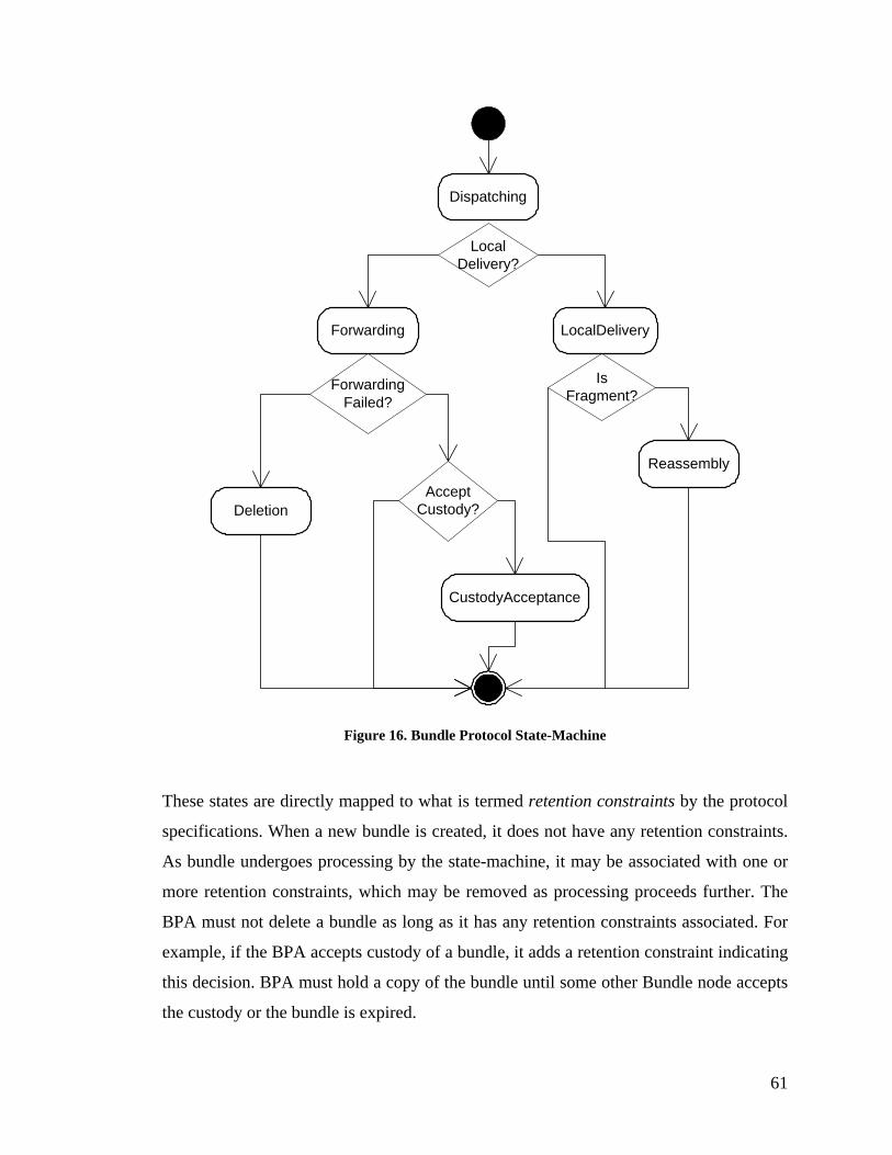
Dispatching
Forwarding LocalDelivery
LocalDelivery?
ForwardingFailed?
Deletion
CustodyAcceptance
AcceptCustody?
IsFragment?
Reassembly
Figure 16. Bundle Protocol State-Machine
These states are directly mapped to what is termed retention constraints by the protocol
specifications. When a new bundle is created, it does not have any retention constraints.
As bundle undergoes processing by the state-machine, it may be associated with one or
more retention constraints, which may be removed as processing proceeds further. The
BPA must not delete a bundle as long as it has any retention constraints associated. For
example, if the BPA accepts custody of a bundle, it adds a retention constraint indicating
this decision. BPA must hold a copy of the bundle until some other Bundle node accepts
the custody or the bundle is expired.
61

An out-bound or an incoming bundle is placed in the dispatching state, after its
destination route has been determined by consulting to the BP-Router component. If the
bundle is to be destined for local delivery and is a complete bundle then it is delivered to
the AA. If such bundle is a fragment, its state is changed to reassembly and it is kept in
the processing queue until all the fragments are reassembled and ADU is delivered to the
AA, or the fragments expire. If the bundle in dispatching state has to be forwarded to
another Bundle node and forwarding is failed then the bundle is deleted. On the other
hand if bundle is forwarded successfully and its custody acceptance is requested, the
BPA can accept the custody depending upon the local policy. If it does so, then the
bundle is kept in custody-acceptance state. The bundle is removed from the processing
queue if it does not have any retention constraints.
Configuration File
The BPA component uses a configuration file in order to load configuration parameters
at the startup. BPA class is also responsible for loading and parsing the contents of the
configuration file. The file consists of name-value tuples. The tuples are separated by a
‘;’ sign and white spaces are ignored. Within each tuple, the filed name and value are
separated by a ‘=’ sign and white spaces are ignored. The current implementation uses
four tuples: local EID, report-to EID, TCP listening port and Bluetooth listening channel
ID. The syntax of the file is generic enough to add more entries.
5.3.2. Bundle and Admin-Record Classes
This class represents a data-structure for a bundle message. It provides the API for the
following operations:
It parses a bundle message in binary format, and extracts different header fields
to store in the respective member variables.
62

In the BPA, a bundle message is stored in parsed form. This class provides the
API for setting and getting values of different fields of header. Hence a bundle
message can be processed and modified efficiently.
It composes a binary bundle message using the information stored in different
fields.
This class stores the payload in binary format, which is delivered to the AA as it is.
Nevertheless, if the bundle is an administrative record then it further decomposes it and
creates an object of Admin-Record class, which provides the API for further analysis of
the payload.
5.3.3. BP-Router Class
This class maintains the routing records for BPA. It reads the entries from a routing file,
on program startup. Entries in the file are stored in the following format, one per line:
<EID> <Transport Type> <Priority> <Node Address> <Service Identifier>
Each field in the entry is separated by one or more white space characters. The first field
contains EID in standard URI format, as explained in Chapter 3. Transport Type field
denotes underlying link-layer technology, used to select corresponding convergence
layer adapter. Currently, two values are defined: ‘TCP’ for the Internet connections and
‘RF_Comm’ for Bluetooth connections. These values are case insensitive. Priority field
is an unsigned numeric value, which is used for routing decisions by the static routing
algorithm for selecting the high priority route in case multiple routing entries exist for a
particular destination. Node Address is a transport-type-dependent field denoting IPv4
addresses for TCP or Bluetooth device address for RF_Comm. Service Identifier is again
a transport dependent numeric value, usually used by protocol stacks for selecting the
application that uses the particular service identified by this value. For TCP, it
corresponds to the ‘port number’ a listening socket is accepting connections on, and the
‘channel ID’ for Bluetooth connections.
63

BP-Router class is derived from CBase and MEventNotifier classes, and uses the timer-
based observer design pattern, as used by some other components. Hence, its callback
function is called in regular intervals, simulating a thread like parallel execution of the
component. Each time, the records from the routing file are updated; hence entries can
be modified without restarting the program.
DTN specification documents, at the moment, do not define any mechanism for routing
information propagation. In fact no routing algorithm has been selected at all, as this is
an on going research area. At the moment, BP-Router class also does not implement any
sophisticated algorithm for routing decisions. Routes are statically defined in the routing
file and simpler algorithms, such as static routing and flooding, are used for routing
decisions. When BPA component enquires the router object for some routing
information, it provides information to use for a particular routing algorithm. In case of
static routing algorithm, the router object simply selects the first route with highest
priority. In case of flooding algorithm, all routing entries stored are used to forward
bundles. BPA maintains a flooding queue, holding signatures (which comprises source
EID, creation timestamp and fragmentation information, if applicable) of the bundles
forwarded, to prevent routing loops.
Nevertheless, since BP-Router component performs route updating asynchronously, it
can be extended to determine routes by other means such as neighbor discovery in which
it determines surrounding devices forming an ad hoc network using Bluetooth or
WLAN. Such information can be used by routing algorithms such as flooding. In future,
DTN protocol specification documents may define additional protocols for routing
information propagation (e.g. PRoPHET), which can be incorporated into modular
architecture of BPA or BP-Router components. In the current implementation, the
Bluetooth CLA detects other devices in the neighborhood and this information is stored
in the BP-Router component. BPA can enquire the routes by specifying a particular
algorithm. In case of the flooding algorithm, the BP-Router component returns routes to
all the devices in the neighborhood, from its NeighborhoodQ.
64

5.3.4. EID Lookup Record Class
This simpler class is used in order to exchange routing information between BP-Router
and BPA components. It implements a linked-list, each node of which contains a single
routing entry stored in BP-Router component. The Number of nodes in the list depends
upon the routing algorithm used. The same class can be utilized to add new entries into
BP-Router by BPA component, as well.
5.4. Application Agent Classes
Application Agent component provides a seamless interface to application programs, via
Symbian IPC mechanism, for utilizing DTN communication. As described in previous
chapter, Symbian provides a client-server framework for IPC. The AA component
executes as application server. An application program can connect to the server. When
this IPC session is created, the application registers for a particular service such as ‘DTN
file transfer’, by providing an application tag. The application tag is used by application
agent to demultiplex incoming bundle payloads, and is used in EIDs based on DTN
URIs. While the IPC session is maintained, DTN applications can send and receive their
data identified by the tag. Application Agent maintains two queues for incoming and
outgoing application data units. The incoming data is not discarded if the session with
corresponding application program does not exist. In such case, the application program
can receive the data whenever it establishes a session with the AA, using a particular
application tag for registration.
A mechanism is provided in Bundle node UI to send and receive test bundles. In this
case, no registration is required and the UI directly accesses queues for sending or
receiving ADUs.
65

The classes used in the design of the AA component are illustrated in Figure 17 and are
discussed in detail below.
CDTNServer
CServer
CActive
CDTNSession
1 0..*
CSession
CShareableSession
RMessageCBPACSchedularTimer
MEventNotifier
Figure 17. AA classes
5.4.1. Symbian Client-Server Framework Classes
The classes shown in above figure follow a fixed design pattern of Symbian client-server
framework. The server application creates a server object, which waits for new IPC
session requests. When a client program requests the kernel to establish a connection
with the server program, the kernel dispatches a session request to the server program.
This logic is built into the framework provided by CServer class. Upon receiving this
request, a session object for that IPC connection is created by the server object. While
the session is established, the client program can issue synchronous or asynchronous
service requests. The actual logic of service execution is handled in CSession class. A
session object receives service request parameters in the object of the RMessage class.
When the client program terminates the session, the framework deletes the
corresponding session object.
5.4.2. DTNServer Class
The server class is an Active Object, waiting for new IPC session requests. It maintains
two queues for holding incoming and outgoing ADUs. Additionally, it uses the timer-
66

based observer design pattern for multiplexing and demultiplexing the outgoing and
incoming ADUs, respectively. It performs the following operations in its callback
function periodically:
Iterates through all the session objects to extract outgoing ADUs and places them
in the queue along with application tag for corresponding registration.
Iterates through all the incoming ADUs in the corresponding queue and hands
over them to the corresponding session object if found any.
Hands over new outgoing ADUs to BPA
Extracts new incoming ADUs from BPA. The notification of success or failure
while sending outgoing ADUs is also received in the same channel.
The server object registers only one session per application tag. That is, it refuses to
register an application for a service if another application is already registered for that
service. This simply results in the graceful termination of the new IPC session by the
framework.
5.4.3. DTNSession Class
The session class receives the request messages from the client via the IPC framework.
Each message comprises a message type and zero or more arguments. The session class
decodes the message type in order to determine type of service requested and performs
the corresponding operations, synchronously or asynchronously. Four types of requests
are handled by current implementation:
A registration request is serviced synchronously. This must be the very first
request issued by client programs. The session is closed if any other request is
issued in prior to the registration request. The session is also terminated if
another session is already established for that registration. The client application
must terminate the session in order to cancel the registration.
67

A transmission request is serviced asynchronously. An outgoing ADU is created,
using the arguments passed along, and buffered temporarily. The session object
then waits for the completion of request asynchronously. The server object
extracts this ADU and hands over to BPA. When BPA notifies about the
transmission status, whether success or failure, the client is informed.
A reception request is also serviced asynchronously. The client program requests
for any ADU received for the particular registration. The request completes when
either any ADU for that registration is sent to client, or the request is canceled by
the client.
A cancel request cancels any pending asynchronous request. Naturally, it applies
to transmit or receive requests only.
5.5. User Interface Classes
UI classes follow a fixed design pattern of Symbian GUI applications. They create and
start other components, directly or indirectly. They provide graphical interface, in the
form of menus and dialog boxes, to users for configuring and using Bundle node
services. The relationship between the classes is illustrated in Figure 18. The user
interface framework varies for different variants of Symbian OS. The classes shown in
the figure correspond to Series80 implementation, and may vary for other builds. A brief
description is provided below. For details, consult Symbian SDK documentation and
other literature such as [HAR03].
CEikApplication
CBPAApplication
CEikDocument
CBPADocument
CEikAppUi
CBPAUi
CCoeControl
CBPAView
CBPACAppAgentBPA_UIControls
Figure 18. UI classes
68
In Symbian OS, every GUI application is a DLL and CBPAApplication class simply
provides a startup entry point for the DLL. CBPADocument class does nothing but
creating the UI object. CBPAUi class handles all the user inputs. It also creates BPA and
AA components on startup. CBPAView class provides a mechanism for drawing and
printing on screen. BPA class uses its services to print information and debugging
messages.
Some simple classes in BPA_UIControls package create dialog boxes for getting more
information from the user about the requested operations. For example, one dialog box
enquires about bundle sending options. Another provides interface for file selection.
5.6. DTN Applications
As described in Chapters 2 and 3, DTN defines a new paradigm for communication, and
a variety of applications can use the Bundle protocol. This is an ongoing research area
and no particular structure for such applications has been defined so far. A simple
application has been developed during this thesis work for demonstration purposes. It
sends and receives files using Bundle protocol. More applications can be developed
using Symbian client-server framework for IPC. This section briefly describes the
framework and design patterns of client applications, which can connect to and utilize
Bundle node server application. For more details, consult Symbian SDK documentation
and other literature, such as [HAR03].
5.6.1. DTN-Socket Class
This class provides the API for establishing a session with the server (i.e. Bundle node),
sending and receiving data, and closing the session. It is illustrated in Figure 19 and
provides the following functions for using Bundle protocol services.
69

Connect() function establishes a session with server.
Register() function registers for a particular service. The name of service is
provided in argument as a descriptor. This operation completes synchronously.
Send() function sends request for transfer of data. The data and meta-data (i.e.
options for sending data e.g. destination address etc.) are packed in a data-
structure and passed as the argument of the function. This operation completes
asynchronously.
Receive() function checks for any data received. This operation completes
asynchronously when data is available for this registration.
Cancel() function cancels any pending receive or send operation.
Close() function closes the session.
RSessionBase RDTNSocket
Figure 19. DTN-Socket class
5.6.2. Application Design Principles
A DTN application can be as sophisticated as a web browser or as simpler as basic
console-based FTP client, as far as data processing presentation is concerned. DTN
communication is as simple as using a socket. The IPC based interface, as described
above, is asynchronous. Application should create an object of DTN-Socket class and
register for a particular service. It may then issue request for sending or receiving data.
For sending request, it should pack all the data and metadata in a data-structure defined
in the implementation. Meta-data includes destination EID, lifetime, custody transfer
requests etc.
Applications can use Active Objects or can just wait synchronously for the completion
of operation, by blocking the execution. The latter is achieved by calling
70
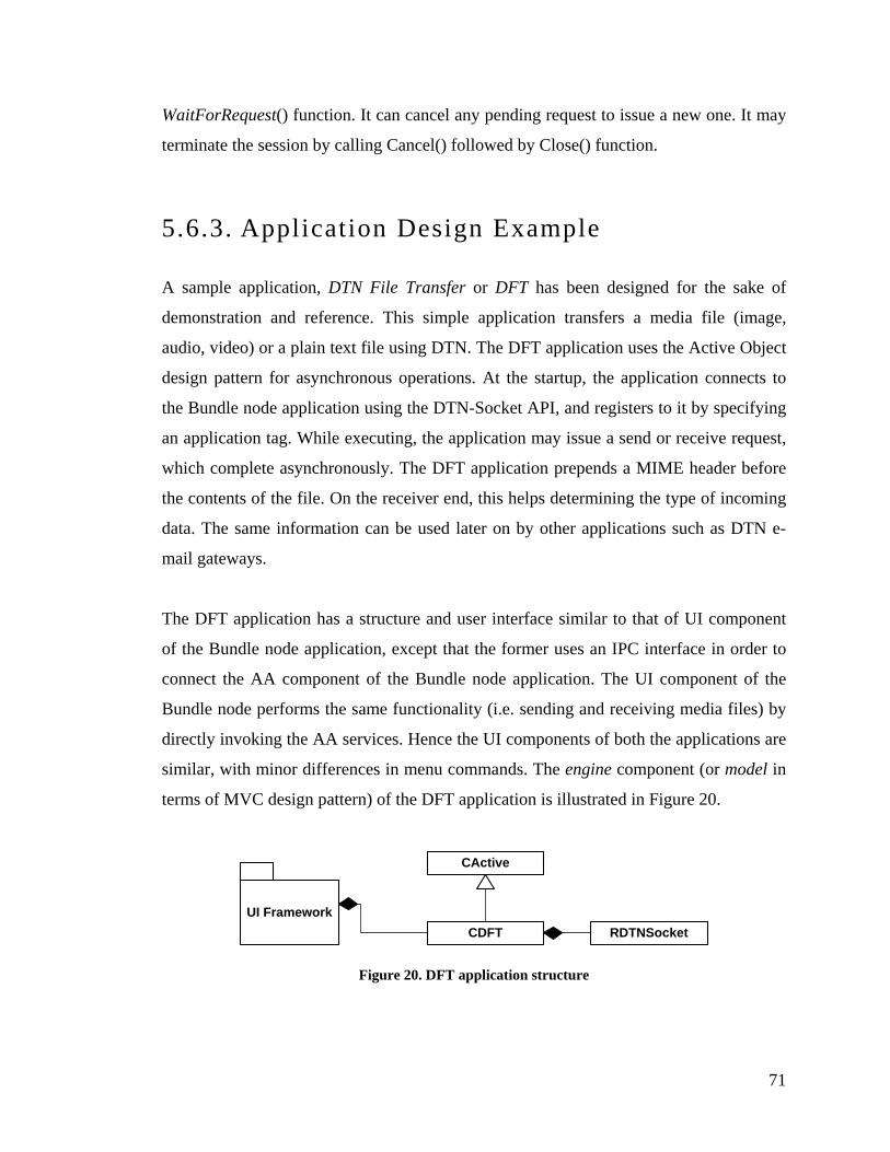
WaitForRequest() function. It can cancel any pending request to issue a new one. It may
terminate the session by calling Cancel() followed by Close() function.
5.6.3. Application Design Example
A sample application, DTN File Transfer or DFT has been designed for the sake of
demonstration and reference. This simple application transfers a media file (image,
audio, video) or a plain text file using DTN. The DFT application uses the Active Object
design pattern for asynchronous operations. At the startup, the application connects to
the Bundle node application using the DTN-Socket API, and registers to it by specifying
an application tag. While executing, the application may issue a send or receive request,
which complete asynchronously. The DFT application prepends a MIME header before
the contents of the file. On the receiver end, this helps determining the type of incoming
data. The same information can be used later on by other applications such as DTN e-
mail gateways.
The DFT application has a structure and user interface similar to that of UI component
of the Bundle node application, except that the former uses an IPC interface in order to
connect the AA component of the Bundle node application. The UI component of the
Bundle node performs the same functionality (i.e. sending and receiving media files) by
directly invoking the AA services. Hence the UI components of both the applications are
similar, with minor differences in menu commands. The engine component (or model in
terms of MVC design pattern) of the DFT application is illustrated in Figure 20.
CDFT
CActive
RDTNSocketUI Framework
Figure 20. DFT application structure
71

The DFT class implements a callback function, which is called by the framework when
the asynchronous request completes. If a file is sent then the Bundle node notifies the
DFT application, when it successfully forwards the Bundle to next node. In the current
application, no end-to-end acknowledgement mechanism is provided. If the application
requests for reception of a file, it completes when the file is received. The incoming data
is stored in a file. A new request placed always cancels the previous one. New DTN
applications should use a similar pattern.
5.7. Summary
In this chapter, a detailed description of implementation of the Bundle node for Symbian
platform was presented. Using a bottom-up approach, some utility classes were
described first, followed by the classes used in each component. Finally the UI
components was described, which instantiates all the components and provides the entry
point for the application startup. The last section discussed some guidelines for
designing DTN applications, which can use the Bundle node’s services using native IPC
mechanism of Symbian platform. The design of a sample DTN application was also
presented as a reference. Having discussed the detailed design, the next chapter focuses
on testing and demonstration of the software.
72
6. VERIFICATION AND DEMONSTRATION
This chapter focuses on some verification techniques employed for the B
application testing. First, different types of testing performed for the
described. Later sections describe a demonstration setup, presented in a conf
6.1. Verification
Verification or testing is the integral part of research and development l
significant effort has been placed for verification of software before it has b
publicly. A complete description of testing plan and test cases is beyond the
document. In the following, a brief description of different test strategies is g
undle node
software are
erence.
ife cycle. A
een released
scope of this
iven.
73

6.1.1. Functional Testing
Functional testing verifies the correctness of algorithms and protocols, validating that
software functions as well as described in requirement and design specifications, from
user’s perspective. Individual components (classes or modules) are not tested separately,
as done in unit testing. Rather overall behavior of integrated components is evaluated.
The following aspects of software behavior are considered as metrics, while performing
functional testing:
The functionality of application. Each component and class works exactly as
described in protocol specification documents and software design description.
The software stability during execution. The application must not crash at any
stage. It should be able to handle unwanted scenarios gracefully, such as invalid
inputs, resource unavailability. It should start and exit gracefully.
The fair utilization of resources. Software uses different resources available in
the execution environment, such as memory, processing power. It should acquire
and free those resources gracefully. There must not be memory leaks. No
component should create a deadlock, consuming all the processing power
forever.
Functional testing has been performed mostly by using emulator and debugger. For
every use case, the code has been stepped-into and iterated-through. Inputs are either
provided via UI component (e.g. when user initiates a bundle transmission) or they come
from network (e.g. when the application receives a bundle from another instance of the
application). For every input, the complete path of execution is traced to eliminate
logical bugs. A logging mechanism is provided to print informational and debugging
messages on screen. This helps tracing problems, while the software runs on real device.
Using same techniques and tools, memory leaks have been detected and eliminated to
maximum, in order to ensure the stability of software.
74

6.1.2. Interoperability Testing
The purpose of interoperability testing is to verify the protocol using a reference design.
This provides a next level of confidence, after functional testing, regarding the
correctness of algorithms and protocols. A reference implementation, DTN2 [DTNRG],
has been used throughout the design and verification life cycle for interoperability
testing. In the testing, the version of the reference design used was 2.2.0, latest package
taken from the CVS repository available at that time.
6.1.3. Performance Testing
Performance testing for measurements and analysis has been conducted on the stable
working application. Usually, the measurements are compared with some reference data
to show performance boost. Since DTN architecture is in early stages of research and
development, performance comparisons are out of the scope of this thesis work and
hence the measurements are not compared with any reference data. Nevertheless, some
statistics have been collected in terms of end-to-end delay, to show performance of
application, while using different communication links. End-to-end delay is the sum of
transmission delay, propagation delay, queuing delay and the nodal processing delay
[ROSS03]. The test setup is shown in Figure 21.
WLAN (Ad Hoc)
a.
Bluetooth
b.
Figure 21. Performance Testing Setup
75
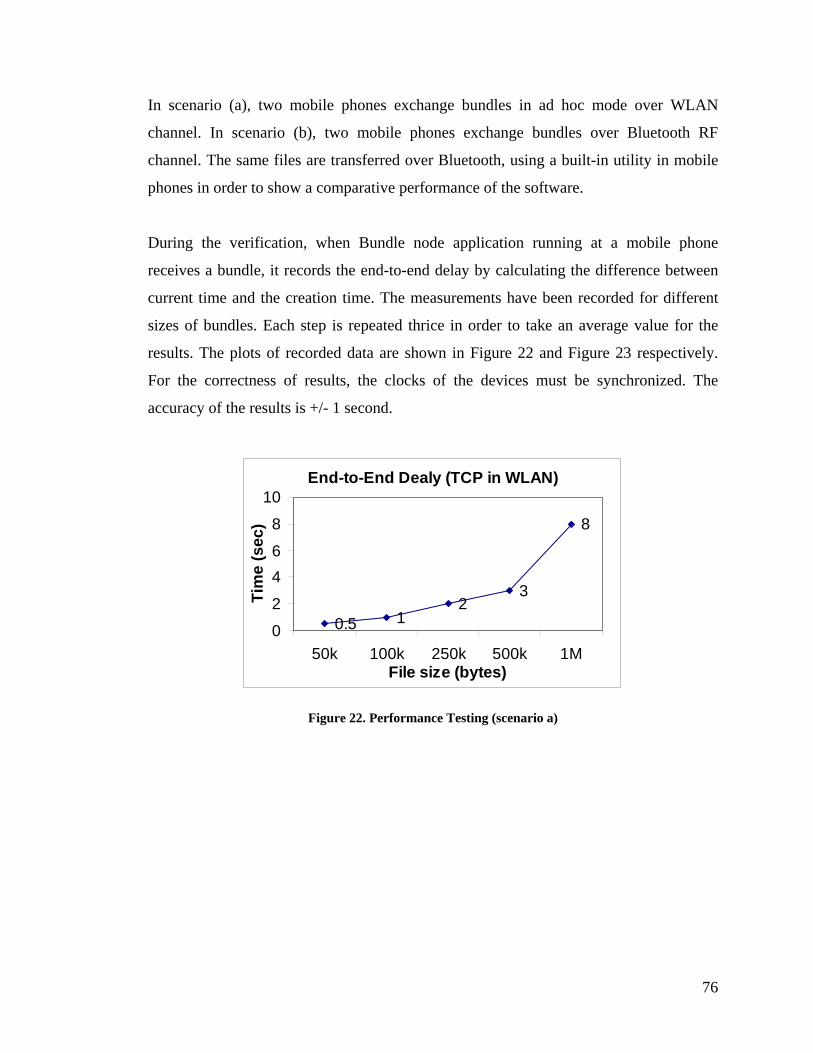
In scenario (a), two mobile phones exchange bundles in ad hoc mode over WLAN
channel. In scenario (b), two mobile phones exchange bundles over Bluetooth RF
channel. The same files are transferred over Bluetooth, using a built-in utility in mobile
phones in order to show a comparative performance of the software.
During the verification, when Bundle node application running at a mobile phone
receives a bundle, it records the end-to-end delay by calculating the difference between
current time and the creation time. The measurements have been recorded for different
sizes of bundles. Each step is repeated thrice in order to take an average value for the
results. The plots of recorded data are shown in Figure 22 and Figure 23 respectively.
For the correctness of results, the clocks of the devices must be synchronized. The
accuracy of the results is +/- 1 second.
End-to-End Dealy (TCP in WLAN)
0.5 12
3
8
0
2
46
8
10
50k 100k 250k 500k 1MFile size (bytes)
Tim
e (s
ec)
Figure 22. Performance Testing (scenario a)
76
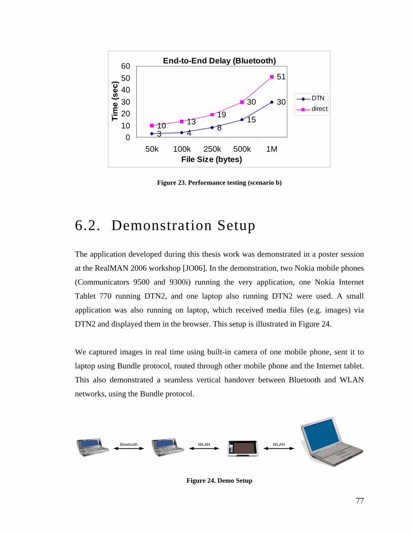
End-to-End Delay (Bluetooth)
3 4 815
30
10 1319
30
51
0102030405060
50k 100k 250k 500k 1MFile Size (bytes)
Tim
e (s
ec)
DTNdirect
Figure 23. Performance testing (scenario b)
6.2. Demonstration Setup
The application developed during this thesis work was demonstrated in a poster session
at the RealMAN 2006 workshop [JO06]. In the demonstration, two Nokia mobile phones
(Communicators 9500 and 9300i) running the very application, one Nokia Internet
Tablet 770 running DTN2, and one laptop also running DTN2 were used. A small
application was also running on laptop, which received media files (e.g. images) via
DTN2 and displayed them in the browser. This setup is illustrated in Figure 24.
We captured images in real time using built-in camera of one mobile phone, sent it to
laptop using Bundle protocol, routed through other mobile phone and the Internet tablet.
This also demonstrated a seamless vertical handover between Bluetooth and WLAN
networks, using the Bundle protocol.
Bluetooth WLAN WLAN
Figure 24. Demo Setup
77

The screen-shots of the application running on mobile phone for sending the images
using DTN, and the application running on the laptop for receiving and displaying the
images using DTN, are shown in Figure 25 and Figure 26 respectively.
Figure 25. DTN application for Symbian Mobile-phone screen-shot
78

Figure 26. Screenshot of received image at laptop
6.3. Software Release
The code of the software developed during the thesis work has been released in public
domain under GNU GPL license. This would provide the researchers with the further
research and development opportunities, which would help extending and enhancing the
work carried out so far. For more information, visit the following website:
http://www.netlab.tkk.fi/u/jo/dtn/index.html
79

6.4. Summary
A brief description of different verification techniques was provided in this chapter. A
demonstration setup was also explained to show various application scenarios of DTN.
In the next chapter, conclusions and recommendations drawn during the thesis work are
discussed.
80
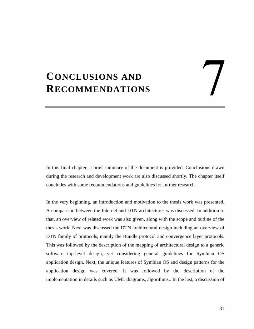
7. CONCLUSIONS AND RECOMMENDATIONS
In this final chapter, a brief summary of the document is provided. Conclu
during the research and development work are also discussed shortly. The c
concludes with some recommendations and guidelines for further research.
In the very beginning, an introduction and motivation to the thesis work w
A comparison between the Internet and DTN architectures was discussed. I
that, an overview of related work was also given, along with the scope and o
thesis work. Next was discussed the DTN architectural design including an
DTN family of protocols, mainly the Bundle protocol and convergence lay
This was followed by the description of the mapping of architectural design
software top-level design, yet considering general guidelines for S
application design. Next, the unique features of Symbian OS and design pa
application design was covered. It was followed by the descript
implementation in details such as UML diagrams, algorithms.. In the last, a d
sions drawn
hapter itself
as presented.
n addition to
utline of the
overview of
er protocols.
to a generic
ymbian OS
tterns for the
ion of the
iscussion of
81

some testing strategies, employed for the verification of the software developed during
the thesis work, was presented.
In earlier chapters (the first and the second), a brief analysis of the Internet family of
protocols was given with a focus on functional and performance issues arising with the
emergence of mobile ad hoc networks. Different solutions proposed for these issues
were mentioned briefly, and the approach used by DTN was discussed in detail. DTN
defines an overlay network on top of existing heterogeneous networks. It uses EID-based
generic naming-scheme along with concepts such as late binding, multi-graph routing
tables, in order to deal routing problems in heterogeneous networks where no single
routing solution can work. It uses notion of virtual messaging; a message bundles all the
application level data and meta-data into one data-unit, called bundle, in order to
minimize transactions between sender and receiver. This as opposed to conversational
style protocols such as HTTP, which are ill-suited for intermittent connections. DTN
also does not follow end-to-end connectivity paradigm strictly. The communication may
commence even if no connected path to destination is available at the moment. It
introduces a concept of custody transfer, in which the bundles are moved away from
source into the network closer to the destination. Hence for final delivery, source node is
not necessarily involved, breaking end-to-end model. DTN supports multiple transport
and network topologies via one or more convergence layer adapter. The main role of
CLAs to provide a generic interface to Bundle layer for point-to-point reliable delivery
services between the bundle nodes. We have proposed a neighborhood discovery
mechanism for Bluetooth convergence layer, using SDP. The information gathered by
this mechanism can be utilized by routing protocols such as flooding and PRoPHET.
DTN is an emerging paradigm for communication across a set of heterogeneous
networks and protocols, each with divergent and distinct requirements such as quality of
service, delays, routing, queuing, power, storage and applications. For example, a delay-
tolerant network may comprise a set of sensors nodes on some planet using a satellite
connection for deep space communication for sending data to earth. Being a relatively
new area, research is going on in many areas to define and refine protocols to support a
82

larger set of networks and protocol families. Routing protocols for route information
propagation, policy based statistical and heuristic routing algorithms, custody transfer to
non-singleton nodes, multicasting in DTN, uses of URI schemes to multiplex application
data, security issues in DTN, convergence layer designs for non-conventional transport
technologies such as SMS, MMS or flash disks, DTN aware application design or
gateway application design enabling legacy applications to use DTN etc. are to name a
few.
This thesis work can be extended in several ways mentioned above. At the moment it
supports only trivial routing algorithms such as static routing and flooding. The BP-
Router component can be extended to incorporate more complex routing algorithms,
such as PROPHET, Swarm routing [KASS01]. Integration of Bundle Security Protocol
is also one of the primary future goals. New applications design such as FTP over DTN,
Web over DTN is also an area of interest. Automatic time-synchronization among the
devices in an ad hoc network requires some research and development activity.
Finally, real word testing of applicability and measurements is also very important, as
exploring DTN for real world inter-personal communication using mobile phones was
the primary motivation factor of this work.
83

References
[COMER] Douglas E. Comer, “Internetworking with TCP/IP Vol. 1”, 4th ed., Prentice
Hall, 2000.
[BRAY] Jennifer Bray, Charles F. Sturman, “Bluetooth : Connect without cables”, 1st
ed., Prentice Hall, 2000.
[BALA97] Hari Balakrishnan et al., “A Comparison of Mechanism for Improving TCP
Performance over Wireless Links”, IEEE/ACM Transactions on Networking, Vol. 5, No.
6, December 1997.
[TANENBAUM] Andrew S. Tanenbaum, “Comuter Networks”, 4th ed., Prentice Hall,
2003.
[RFC2002] C. Perkins, “IP Mobility Support”, RFC 2002, October 1996.
[RFC4423] R. Moskowitz, P. Nikander, “Host Identity Protocol (HIP) Architecture”,
RFC 4423, May 2006.
[RFC2916] P. Faltstorm, “E.164 numbers and DNS”, RFC 2916, September 2000.
[OTT04] Joerg Ott, Dirk Kutscher, “Why seamless? Towards exploiting WLAN-based
intermittent connectivity on the road”, TERENA networking conference, June 2004.
[BAIG06] A. Baig, L. Libman, and M. Hassan, "Performance Enhancement of On-Board
Communication Networks using Outage Prediction," IEEE Journal on Selected Areas of
Communications (JSAC), 2006. (selected but to-be-appeared, web-source 2006:
http://www.ocean.cse.unsw.edu.au/jsac06.pdf)
84

[BURL03] S. Burleigh, K. Fall, et al., “Delay-Tolerant Networking: An Approach to
Interplanetary Internet”, IEEE Communications Magazine, June 2003.
[FALL03] Kevin Fall, “A Delay-Tolerant Network Architecture for Challenged
Internets”, Proceedings SIGCOMM, August 2003.
[JACK05] Joab Jackson, “The Interplanetary Internet”, IEEE Spectrum, August 2005.
[JUANG02] Philo Juang et al., “Energy Efficient Computing for Wildlife Tracking:
Design Tradeoffs and Early Experiences with ZebraNet”, ACM ASPLOS-X, October
2002.
[ZHAO05] Wemi Zhao, Mostafa Ammar and Ellen Zegura, "Controlling the Mobility of
Multiple Data Transport Ferries in a Delay-Tolerant Network", INFOCOM 2005
Proceedings IEEE, Vol. 2, 2005.
[PENT04] Alex Pentland, Richard Fletcher, Amir Hasson, “DakNet: Rethinking
Connectivity in Developing Nations”, IEEE Computer magazine, January 2004.
[SNC] Sami Network Connectivity project (websource 2006:
http://www.snc.sapmi.net/).
[BURG06] John Burgess, Brian Gallagher et al., “MaxProp: Routing for Vehicle-Based
Disruption-Tolerant Networking”, Proceedings of IEEE Infocom 2006, April 2006.
[LOC03] Christian Lochert, Hannes Hartenstein et al., “A Routing Strategy for
Vehicular Ad Hoc Networks in City Environments”, IEEE Intelligent Vehicles
Symposium, June 2003.
85

[LEIG06] A. Leiggener, R. Schmitz et al., "Analysis of Path Characteristics and
Transport Protocol Design in Vehicular Ad Hoc Networks", IEEE Semiannual Vehicular
Technology Conference, May 2006.
[SCH05] Simon Schutz, Lars Eggert, et al., "Protocol Enhancements for Intermittently
Connected Hosts", ACM SIGCOMM Computer Communication Review Vol. 35 No. 2,
July 2005.
[NEW04] M. E. J. Newman, J. Park, “Why Social Networks are different from other
types of networks”, Physical Review E, 69, February 2004.
[MUS06] M. Musolesi, C Mascolo, “A Community based Mobility Model for Ad Hoc
Network Research”, RealMAN 2006.
[HUI05] P. Hui, A. Chaintreau, J. et al., “Pocket Switched Networks and Human
Mobility in Conference Environments”, In Proceedings of the ACM SIGCOMM 2005
Workshop on Delay-Tolerant Networking (WDTN), August 2005.
[SYMB06] Worldwide total smartphone device market share stats. (web source 2006
http://www.symbian.com/about/fastfacts/fastfacts.html).
[DTNRG] Delay-Tolerant Networking Research Group, (http://www.dtnrg.org).
[PATRA04] Serqiu Nedenshi, Rabin Patra. “DTNLite: A Reliable Data Transfer
Architecture for Sensor Networks”, 8th International Conference on Intelligent
Engineering Systems, 2004.
[DTNARCH05] V. Cerf, S. Burleigh et al., “Delay-Tolerant Networking Architecture”,
v 5, March 2006
86

[IPN99] Eric Travis, A presentation for IPN, (web source 2006
http://www.ipnsig.org/reports/interinter/index.htm).
[LEG05] J. Leguay, T. Friedman, V. Conan, "DTN Routing in a Mobility Pattern
Space", Proceedings SIGCOMM Workshop on Delay Tolerant Networks, 2005.
[LIND06] A. Lindgren, A. Doria, “Probabilistic Routing Protocol for Intermittently
Connected Networks”, draft-lindgren-dtnrg-prophet-02, March 2006.
[BPSPEC04] K. Scott, S. Burleigh, “Bundle Protocol Specifications” v 4, November
2005.
[TCPCL] M. Demmer, “Protocol for the DTN TCP Convergence Layer”, Internet draft,
March 2006.
[FNV] L. C. Noll, Fowler / Noll / Vo (FNV) hash algorithm (Web source 2006:
http://www.isthe.com/chongo/tech/comp/fnv/).
[HAR03] Richard Harrison, “Symbian OS C++ for Mobile Phones”, Vol. 1, John Wiley
& Sons Ltd., 2003.
[ROSS03] James F. Kurose, Keith W. Ross, “Computer Networking”, 2nd ed., Addison
Wesley, 2003.
[JO06] Omar Mukhtar, Joerg Ott, “Backup and Bypass: Introducing DTN-based Ad-hoc
Networking to Mobile Phones”, ACM RealMAN, May 2006.
[KASS01] I. Kassabalidis et al., “Swarm Intelligence for Routing in Communication
Networks”, Global Telecommunication Conference, 2001.
87