design and implementation of a modular manipulator
TRANSCRIPT

DESIGN AND IMPLEMENTATION OF A MODULAR MANIPULATOR
ARCHITECTURE
By
OGNJEN SOSA
A THESIS PRESENTED TO THE GRADUATE SCHOOL OF THE UNIVERSITY OF FLORIDA IN PARTIAL FULLFILMENT
OF THE REQUIREMENTS FOR THE DEGREE OF MASTER OF ENGINEERING
UNIVERSITY OF FLORIDA
2004

Copyright 2004
by
Ognjen Sosa

To my mother, father and brother.
“If a man empties his purse into his head, no man can take it away from him. An investment in knowledge always pays the best interest.” — Benjamin Franklin

ACKNOWLEDGMENTS
I would like to express my thanks to my entire committee (Dr. Carl Crane, Dr. John
Schueller, and Dr. John Ziegert) for their support of my study. Furthermore, I would like
to extend my thanks to Dr. Robert Bicker (of the University of Newcastle upon Tyne) for
his insightful ideas and hands-on support.
Special thanks go to my advisor Prof. Carl Crane, for his patience with my
endeavors; to Mr. Dave Armstrong, our project manager, for always trying to keep me on
track; and to Tyndall Airforce Base (contract # F08637-00-C6008) for providing
financial support for my studies. I am also grateful to the entire staff of the Center for
Intelligent Machines and Robotics (with distinguished contributions from David Kent,
Tom Galluzzo, Shannon Ridgeway, and Hyun Kwon Jung).
Finally I would like to thank all of my friends and extended family for their moral
support and guidance over the last 7 years. However, without the love and patience of
those closest to me, this work would have never been accomplished. Thus, my greatest
appreciation goes to my mother, Jadranka; my father Darko; and my brother Vedran.
Their pride and recognition of my accomplishments had an immense impact on my
motivation and provided a strong driving mechanism during my studies.
iv

TABLE OF CONTENTS page ACKNOWLEDGMENTS ................................................................................................. iv
LIST OF TABLES...............................................................................................................x
LIST OF FIGURES .......................................................................................................... xii
ABSTRACT.......................................................................................................................xv
CHAPTER 1 INTRODUCTION ........................................................................................................1
1.1 Introduction.............................................................................................................1 1.2 Background.............................................................................................................3 1.3 Joint Architecture for Unmanned Systems (JAUS)................................................4
1.3.1 Overview .....................................................................................................4 1.3.2 Standards .....................................................................................................5 1.3.3 System Topology..........................................................................................7 1.3.4 Component Definition ..................................................................................9 1.3.5 Message Specification ................................................................................10
2 SYSTEM ANALYSIS AND OVERVIEW................................................................13
2.1 Mechanism Overview...........................................................................................14 2.2 Kinematic Analysis of the Puma 762 Robot.........................................................14
2.2.1 Notation ......................................................................................................14 2.2.2 Forward and Reverse Position Analysis.....................................................17 2.2.3 Forward and Reverse Velocity Analysis ....................................................23 2.2.4 Singularity Determination ..........................................................................24 2.3.5 Quaternion Representations........................................................................26
3 PUMA 762 CONTROLLER SYSTEM......................................................................28
3.1 Overview...............................................................................................................28 3.2 Reverse Engineering the Puma 762 Robot ...........................................................29
3.2.1 Existing Architecture..................................................................................29 3.2.2 Encoder and Potentiometer Val Interface...................................................30 3.2.3 Amplifier Digital-to-Analog Converter Signals and Control Lines ...........31
v

3.2.4 Safety..........................................................................................................32 3.2.5 Tuning.........................................................................................................32
3.3 Galil DMC-2100 Functionality.............................................................................33 3.3.1 Command Modes........................................................................................33 3.3.2 Theory of Operation ...................................................................................34
3.4 Galil C/C++ Application Programming Interface (API) ......................................35 4 LOW-LEVEL MANIPULATOR CONTROL COMPONENT .................................37
4.1 Primitive Manipulator Component .......................................................................37 4.1.1 Definition of Coordinate Systems ..............................................................37
4.1.1.1 Global coordinate system.................................................................37 4.1.1.2 Vehicle coordinate system ...............................................................37 4.1.1.3 Manipulator base coordinate system ................................................38 4.1.1.4 End-effector coordinate system........................................................38
4.1.2 Component Function ..................................................................................38 4.1.3 Associated Messages ..................................................................................39 4.1.4 Component Description..............................................................................39 4.1.5 Input and Output Messages ........................................................................40
4.1.5.1 Code 0601h: Set Joint Effort ............................................................40 4.1.5.2 Code 2600h: Query Manipulator Specifications ..............................41 4.1.5.3 Code 2601h: Query Joint Effort .......................................................41 4.1.5.4 Code 4600h: Report Manipulator Specifications .............................41 4.1.5.5 Code 4601h: Report Joint Effort ......................................................41
4.2 Primitive Manipulator Applications to the Puma system.....................................44 5 MANIPULATOR SENSOR COMPONENTS...........................................................45
5.1 Manipulator Joint Position Sensor Component ....................................................45 5.1.1 Component Function ..................................................................................45 5.1.2 Associated Messages ..................................................................................45 5.1.3 Component Description..............................................................................46 5.1.4 Input and Output Messages ........................................................................46
5.1.4.1 Code 0602h: Set Joint Positions message ........................................46 5.1.4.2 Code 2602h: Query Joint Positions message ...................................47 5.1.4.3 Code 4602h: Report Joint Positions message ..................................47
5.2 Manipulator Joint Velocity Sensor Component ...................................................47 5.2.1 Component Function ..................................................................................47 5.2.2 Associated Messages ..................................................................................47 5.2.3 Component Description..............................................................................47 5.2.4 Input and Output Messages ........................................................................48
5.2.4.1 Code 0603h: Set Joint Velocities message.......................................48 5.2.4.3 Code 4603h: Report Joint Velocities message.................................48
5.3 Manipulator Joint Force/Torque Sensor Component ...........................................49 5.3.1 Component Function ..................................................................................49 5.3.2 Associated Messages ..................................................................................49 5.3.3 Component Description..............................................................................49
vi

5.3.4 Input and Output Messages ........................................................................49 5.3.4.1 Code 2605: Query Joint Force/Torques ...........................................49 5.3.4.2 Code 4605h: Report Joint Force/Torques ........................................49
5.4 Sensor Component Applications to the Puma System .........................................50 6 MANIPULATOR LOW-LEVEL POSITION AND VELOCITY DRIVER
COMPONENTS .........................................................................................................51
6.1 Manipulator Joint Positions Driver Component ...................................................51 6.1.1 Component Function ..................................................................................51 6.1.2 Associated Messages ..................................................................................51 6.1.3 Component Description..............................................................................52
6.2 Manipulator End-Effector Pose Driver Component .............................................52 6.2.1 Component Function ..................................................................................52 6.2.2 Associated Messages ..................................................................................52 6.2.3 Component Description..............................................................................53 6.2.4 Input and Output Messages ........................................................................53
6.2.4.1 Code 0604h: Set Tool Point message...............................................53 6.2.4.2 Code 0605h: Set End-Effector Pose message ..................................54 6.2.4.3 Code 2604h: Query Tool Point ........................................................54 6.2.4.4 Code 4604h: Report Tool Point .......................................................55
6.3 Manipulator Joint Velocities Driver Component .................................................55 6.3.1 Component Function ..................................................................................55 6.3.2 Associated Messages ..................................................................................55 6.3.3 Component Description..............................................................................55
6.4 Manipulator End-Effector Velocity State Driver Component..............................56 6.4.1 Component Function ..................................................................................56 6.4.2 Associated Messages ..................................................................................56 6.4.3 Component Description..............................................................................57 6.4.4 Code 0606h: Set End-Effector Velocity State message .............................57
6.5 Applications of the Low-Level Driver Components to the Puma System ...........58 7 MID-LEVEL POSITION AND VELOCITY DRIVER COMPONENTS.................61
7.1 Manipulator Joint Move Driver Component ........................................................61 7.1.1 Component Function ..................................................................................61 7.1.2 Associated Messages ..................................................................................61 7.1.3 Component Description..............................................................................62 7.1.4 Code 0607: Set Joint Motion......................................................................63
7.2 Manipulator End-Effector Discrete Pose Driver Component...............................65 7.2.1 Component Function ..................................................................................65 7.2.2 Associated Messages ..................................................................................65 7.2.3 Component Description..............................................................................65 7.2.4 Code 0608h: Set End-Effector Path Motion...............................................66
7.3 Applications of the Mid-Level Driver Components to the Puma System............66
vii

8 OVERVIEW OF SOFTWARE DESIGN...................................................................69
8.1 Overview...............................................................................................................69 8.2 The Interface to the Galil Controller ....................................................................70 8.3 Component Level Software Development............................................................72
8.3.1 Primitive Manipulator State Thread ...........................................................73 8.3.2 Manipulator Sensor Components ...............................................................74 8.3.3 Low-Level Position and Velocity Drivers..................................................75
8.4 Message Level Software Development ................................................................76 8.5 Node Level Software Development......................................................................76 8.6 Node Manager and Communicator.......................................................................77
9 TESTING AND RESULTS........................................................................................78
9.1 Subsystem Commander Component Overview....................................................78 9.2 Case 1: Set Joint Effort .........................................................................................79 9.3 Case 2: Set Joint Position .....................................................................................81
9.3.1 The “Average” Set......................................................................................82 9.3.2 The “Low” Set ............................................................................................84 9.3.3 The “High” Set ...........................................................................................85
9.4 Case 3: Set End-Effector Pose..............................................................................88 9.5 Case 4: Set Joint Velocities ..................................................................................89 9.6 Case 5: Set End-Effector Velocity State...............................................................90 9.7 Case 6: Set Joint Motion.......................................................................................91
9.7.1 Set Joint Motion: Pose 1.............................................................................91 9.7.2 Set Joint Motion: Pose 2.............................................................................93 9.7.3 Set Joint Motion: Pose 3.............................................................................94
9.8 Case 7: Set End-Effector Path Motion..................................................................96 10 CONCLUSIONS AND FUTURE WORK.................................................................99
10.1 Conclusions.........................................................................................................99 10.2 Future Work......................................................................................................101
APPENDIX A EQUATIONS FOR A SPHERICAL HEPTAGON .................................................102
B JAUS MANIPULATOR COMPONENTS: SOURCE CODE.................................104
B.1 The GalilInterface.c File and the Corresponding Header GalilInterface.h ........104 B.2 The Pm.c File and the Corresponding Header Pm.h..........................................117 B.3 The Mjps.c File and the Corresponding Header Mjps.h ....................................130 B.4 The Meepd.c File and the Corresponding Header Meepd.h ..............................141 B.5 The Meedpd.c File and the Corresponding Header Meedpd.h ..........................159 B.6 The Mc.c File and the Corresponding Header Mc.h..........................................178 B.7 The Main.c File ..................................................................................................182
viii
C SOURCE CODE FOR THE USER DEFINED JAUS MESSAGES .......................200
C.1 The JointEffort.c File and the Corresponding Header JointEffort.h..................200 C.2 The JointPosition.c File and the Corresponding Header JointPosition.h...........202 C.3 The EndEffectorPose.c File ...............................................................................204
LIST OF REFERENCES.................................................................................................207
BIOGRAPHICAL SKETCH ...........................................................................................209
ix

LIST OF TABLES
Table page 1-1 The JAUS core message set.....................................................................................9
1-2 Segmentation of command codes by class.............................................................10
1-3 Message header data format...................................................................................12
2-1 Mechanical specifications of the Puma 762 robot .................................................14
2-2 Mechanism parameters of the Puma 762 robot......................................................15
2-3 Closed-loop mechanism parameters of the Puma 762 robot .................................19
3-1 Pin connections between Val and Galil ICM-2900 interconnect modules ............31
3-2 Controller gain values ............................................................................................33
4-1 Set Joint Effort message parameters ......................................................................40
4-2 Report Manipulator Specifications parameters......................................................42
5-1 Set Joint Positions message parameters.................................................................46
5-2 Set Joint Velocities message parameters ...............................................................48
5-3 Report Joint Force/Torque message parameters ....................................................50
6-1 Set Tool Point message parameters .......................................................................54
6-2 Set End-Effector Pose message parameters...........................................................54
6-3 Set End-Effector Velocity State message parameters............................................58
7-1 Set Joint Motion message parameters....................................................................63
7-2 Set End-Effector Path Motion message parameters...............................................67
9-1 The Puma 762 platform specific conversion factors..............................................81
9-2 Values of the K constant and corresponding range of motion parameters ............82
x
9-3 Values of the K constant and “average” set of motion parameters........................82
9-4 Values of the K constant and “low” set of motion parameters ..............................84
9-5 Values of the K constant and “high” set of motion parameters.............................86
A-1 Fundamental formulas for a Spherical Heptagon ................................................102
A-2 Subsidiary formulas for a Spherical Heptagon Set 1 ...........................................103
xi

LIST OF FIGURES
Figure page 1-1 Manipulator linkage parameters for link ij ..............................................................6
1-2 Manipulator linkage parameters for revolute joint j ................................................6
1-3 Manipulator linkage parameters for prismatic joint j ..............................................7
1-4 Architecture hierarchy .............................................................................................8
1-5 Architecture hierarchy of the manipulator control node..........................................8
1-6 The JAUS message header detail...........................................................................11
1-7 Bit layout of message properties............................................................................11
2-1 Puma 762, 6-DOF robot manipulator ....................................................................13
2-2 Labeled kinematic model of the Puma 762 manipulator .......................................15
2-3 Reverse analysis solution tree for Puma 762 robot................................................22
2-4 Wrist singularity of Puma 762 robot......................................................................25
2-5 Forearm boundary singularity of Puma 762 robot.................................................25
2-6 Forearm interior singularity of Puma 762 robot ....................................................26
3-1 Schematic representation entire manipulator system.............................................29
3-2 Arm signal interconnects between Val and ICM-2900 modules ...........................30
3-3 BRK-ON-HI connection diagram..........................................................................32
3-4 Functional elements of a motion control system ...................................................34
3-5 Initializing the Galil libraries .................................................................................35
3-6 Establishing communications with the Galil Controller........................................35
3-7 Closing the connection to the Galil Controller ......................................................35
xii

3-8 Sending commands to the Galil Controller............................................................36
3-9 Resetting the controller ..........................................................................................36
4-1 Joint effort provides basic manipulator mobility ...................................................40
5-1 Joint position sensor component............................................................................46
5-2 Joint velocity sensor component............................................................................48
6-1 Manipulator Joint Positions Driver component .....................................................52
6-2 Manipulator End-Effector Pose Driver component ...............................................53
6-3 Manipulator Joint Velocities Driver component....................................................56
6-4 Manipulator End-Effector Velocity State Driver component ................................57
7-1 Manipulator Joint Move Driver component ..........................................................62
7-2 Manipulator End-Effector Discrete Pose Driver component.................................66
8-1 The galilInterface.c logic flow diagram.................................................................70
8-2 Generic component logic flow diagram.................................................................72
8-3 The Primitive Manipulator state thread logic flow diagram..................................73
8-4 Manipulator Joint Position Sensor logic flow diagram..........................................74
8-5 Manipulator End-Effector Pose Driver logic flow diagram ..................................75
9-1 Subsystem Commander operator graphical user interface.....................................79
9-2 Primitive Manipulator Screen as it responds to the Set Joint Effort message .......80
9-3 External closed-loop control diagram....................................................................81
9-4 Joint step responses using “average” motion parameters ......................................83
9-5 The MJPD screen as motion is completed under the “average” set ......................83
9-6 The MJPD screen as motion is completed under the “low” set.............................84
9-7 Joint step responses using “low” motion parameters.............................................85
9-8 Joint step responses using “high” motion parameters............................................86
9-9 The MJPD screen as motion is completed under the “high” set............................87
xiii

9-10 Subsystem Commander screen showing the final configuration of Puma 762 .....87
9-11 The MEEPD screen as it responds to Set End-Effector Pose message..................89
9-12 The MJVD Screen as it responds to Set Joint Velocities message ........................90
9-13 The MJMD screen showing component status upon completion of pose 1 ..........91
9-14 Joint performance plots for motion parameters set in pose 1 ................................92
9-15 The MJMD screen showing component status upon completion of pose 2 ..........93
9-16 Joint performance plots for motion parameters set in pose 2 ................................94
9-17 The MJMD screen showing component status upon completion of pose 3 ..........95
9-18a Joint performance plots for motion parameters set in pose 3 ................................95
9-18b Joint performance plots for motion parameters set in pose 3 ................................96
9-19 The MEEDPD screen after completion of pose 1..................................................97
9-20 The MEEDPD screen after completion of pose 5..................................................97
xiv

Abstract of Dissertation Presented to the Graduate School of the University of Florida in Partial Fulfillment of the Requirements for the Degree of Master of Engineering
DESIGN AND IMPLEMENTATION OF A MODULAR MANIPULATOR ARCHITECTURE
By
Ognjen Sosa
December 2004
Chair: Carl D. Crane, III Major Department: Mechanical and Aerospace Engineering
The Joint Architecture for Unmanned Systems (JAUS) has successfully established
a well-defined component interface for unmanned mobile systems, but has yet to address
the implications of such systems requiring an on-board robot manipulator. This
configuration is seen in many applications including planetary exploration, hazardous
materials removal, and marine research and is frequently referred to as the vehicle-
manipulator system. The purpose of our study was to develop and implement a set of
JAUS components that will allow for tele-operational (teleop) and autonomous control of
a vehicle-manipulator platform. Teleop control is the control of a system by the direct
input of a human or a computer. Autonomous control is a cooperative mode between the
vehicle and the manipulator.
Testing and implementation of these components was performed on a 6-degree-of-
freedom (6-DOF) Puma 762 robot manipulator (Unimation – Westinghouse, Danbury,
Connecticut) outfitted with a commercially available Galil motion controller (Galil
xv

Motion Control, Inc, Rocklin, California). Successful completion and adequate
compatibility to the outlined JAUS performance specifications would ensure the
inception of the above mentioned components to the latest version of the document’s
Reference Architecture. Even though this modular manipulator architecture is suitable for
both autonomous and teleop control, testing and results were based solely on the input
provided using a graphical user interface on a computer.
xvi

CHAPTER 1 INTRODUCTION
1.1 Introduction
In the past decade, significant technological breakthroughs have led to smarter and
more-reliable unmanned systems. Reliability and robustness of these systems depend on
many factors, most of which are defined in the early stages of design and development.
With an increasing interest in this field and tremendous implications to both civilian and
military use, there is a growing demand for a set of well-defined standards that could
ensure safety, reliability, and interoperability. The Center for Intelligent Machines and
Robotics (CIMAR) at the University of Florida has been involved in developing of one
such standard, in cooperation with the Department of Defense.
The Joint Architecture for Unmanned Systems (JAUS) has successfully established
a well-defined component interface for unmanned mobile systems, but has yet to address
the implications of such systems requiring an on-board robot manipulator. This
configuration is seen in many applications including planetary exploration, hazardous
materials removal, and marine research; and is frequently referred to as a
vehicle-manipulator system. The purpose of our study is to develop and implement a set
of JAUS components that will allow for tele-operational (teleop) and autonomous control
of a vehicle-manipulator platform. Teleop control is defined as the control of a system by
the direct input of a human or a computer. Autonomous control is defined as a
cooperative mode between the vehicle and the manipulator. The components focus on a
serial manipulator comprising of any number of prismatic and revolute joints. Parallel
1

2
mechanisms are not addressed as a part of our study. The components are grouped
according to function into the following categories:
• Low-level manipulator control components: The one component in this category allows for low-level command of the manipulator joint-actuation efforts. This is an open-loop command that could be used in a simple tele-operation scenario. The component in this category is listed as follows:
o Primitive manipulator component
• Manipulator sensor components: These components, when queried, return instantaneous sensor data. Three components are defined that return respectively joint positions, joint velocities, and joint torques or forces. The components in this category are listed as follows:
o Manipulator joint position sensor component
o Manipulator joint velocity sensor component
o Manipulator joint force/torque sensor component
• Low-level position and velocity driver components: These components take as inputs the desired joint positions, the desired joint velocities, the desired end-effector pose, or the desired end-effector velocity state. Closed-loop control is implied. No path information is specified. The components in this category are listed as follows:
o Manipulator joint positions driver component
o Manipulator end-effector pose driver component
o Manipulator joint velocities driver component
o Manipulator end-effector velocity state driver component
• Mid-level position and velocity driver components: Two components are grouped under this heading. The first takes as input the goal values for each joint parameter at several time values together with motion constraints (i.e. maximum joint velocity, maximum acceleration, and maximum deceleration). The second takes as input a series of end-effector poses at specified time values. Closed-loop control is implied. The components in this category are:
o Manipulator Joint Move Driver Component
o Manipulator End-Effector Discrete Pose Driver Component.

3
Testing and implementation of these components is performed on a
6-degree-of-freedom (6-DOF) Puma 762 robot manipulator outfitted with a commercially
available Galil motion controller. Successful completion and adequate compatibility to
the outlined JAUS performance specifications would ensure the inception of the
above-mentioned components to the latest version of the document’s Reference
Architecture. Even though this modular-manipulator architecture is suitable for both
autonomous and teleop control, testing and results are based solely on input provided
using a graphical user interface on a computer.
1.2 Background
Robot manipulators are used in a wide variety of applications; but usually follow
user-defined paths, thus requiring teleop control. In the case of a manipulator aboard an
autonomous mobile system, there is a growing demand for the manipulator and the
vehicle to be able to cooperate, allowing the system to autonomously complete
more-complex tasks (such as sample acquisition, instrument placement, and mobility
assistance). This problem was first addressed by NASA in the mid 1990s as the first rover
missions to Mars were planned. Technology developed in 1998 [1] allowed robot
manipulators aboard the vehicles to autonomously acquire small rock samples
(designated by the user) within 1 meter away; and to place instruments on targets less
than 5 meters away. These capabilities are accomplished with onboard vision sensors
using stereo processing algorithms developed by Matthies [2]. This application showed
the autonomous behavior of the manipulator but did not consider other high-level vehicle
functions. The algorithms were designed to be portable, extendible, and reusable across
many vehicle platforms. Testing was successfully completed on Rocky 7 [3].

4
Other inhospitable environments (such as oceans) are frequently explored using
underwater vehicle-manipulator systems (UVMS). These systems are mostly used for
inspection, drilling, mine countermeasures, and surveying [4]. In most applications,
UVMS operates as a master-slave configuration, and as such is prone to a few
deficiencies. Challenges include correctly modeling the nonlinear hydrodynamic effects
of the environment; and improving the performance of motion control encompassing
singularity avoidance, obstacle detection, and power optimization [5]. Recent research [6]
in the field of UVMS uses a unified force control approach, which combines impedance
control with hybrid position/force control by means of fuzzy switching to perform
autonomous underwater manipulation.
1.3 Joint Architecture for Unmanned Systems (JAUS)
1.3.1 Overview
The Joint Architecture for Unmanned Systems (JAUS) [7] is being developed in
conjunction with the Department of Defense and many other members of industry and
academia for use in research, development and acquisition of unmanned systems. The
current version of the document is divided into three large volumes; the JAUS Domain
Model (Vol. I), JAUS Reference Architecture (RA-Vol. II), and JAUS Document Control
Plan (Vol. III). The JAUS Working Group was chartered to reduce lifecycle costs, and
integration and development time; to provide a framework for technology insertion; to
accommodate expansion of existing systems with new capabilities.
Volume I defines known and prospective operational requirements of unmanned
systems. Volume III defines the process used to identify and track requested changes to
accepted JAUS documentation. Components developed as a part of our study affect all
three parts of Volume II because it is concerned with aspects of component design. The

5
main purpose of the Reference Architecture (RA) is to describe all functions and
messages that shall be used to design new components. Joint Architecture for Unmanned
Systems defines components for all classifications of Unmanned Systems, from teleop to
autonomous. As a particular system evolves, the architecture is already in place to
support more-advanced capabilities. To meet this requirement, four technical constraints
are imposed on JAUS:
• Platform independence: Since unmanned systems will be based on a variety of missions, no assumptions are made regarding the vehicle platform.
• Mission isolation: Joint Architecture for Unmanned Systems defines a mission as the ability to gather information about or to alter the state of the environment in which the platform is operating. This allows the developer to construct the system to support a variety of missions.
• Computer hardware independence: Advances in computer technology over the past couple of decades have seen rapid growth. The JAUS computer hardware constraint was put in place to ensure software and hardware portability as new systems are developed in the future.
• Technology independence: This constraint is similar to hardware independence, but focuses more on technical approach [7, 8]. In this particular application, the architecture makes no assumption regarding the method used to obtain joint positions. For example different manipulators could be outfitted by different position sensors that include encoders, potentiometers, or rotational variable differential transformers.
1.3.2 Standards
The Reference Architecture (RA) document defines the JAUS specific protocol for
transmission of messages. Aside from computer code specifications, this section also
standardizes mathematical notations. The notation used in this thesis is standard to many
popular robotics textbooks; specifically, we use the definitions covered by Crane and
Duffy [9]. To standardize the method of referencing manipulator links (or joints), Figures
1-1 through 1-3 illustrate the notation that will be used later in the document. Figure 1-1

6
shows the parameters used for link ij. Figure 1-2 and Figure 1-3 show additional
parameters used to define rotational joints and prismatic joints, respectively.
Si Sj
aij
aij
αij
Figure 1-1. Manipulator linkage parameters for link ij (Source: Crane C., Duffy J.,
Kinematic Analysis of Robot Manipulators, Cambridge University Press, 1998, p. 21, Figure 3.2)
Link length aij is measured as the perpendicular distance between joint axis i and
joint axis j along the unit vector aij. Note that it can have a negative value. Twist angle
αij is the angle between Si (unit vector along joint axis i) and Sj (unit vector along joint
axis j) measured in a right hand sense about aij.
Sj
ajk
aij
Sj
θj
Figure 1-2. Manipulator linkage parameters fo t j (Source: Crane C., Duffy r revolute join
J., Kinematic Analysis of Robot Manipulators, Cambridge University Press, 1998, p. 22, Figure 3.5)

7
Constant joint offset Sj is measured as the perpendicular distance between link aij
and Link ajk along the unit vector Sj. Note that it can have a negative value. Variable
joint angle θj is the angle between aij (unit vector along link ij) and ajk (unit vector a
link jk) measured in a right hand sense ab
long
out Sj.
Sj
ajk
aij
Sj
θj
J., Kinematic Analysis of Robot Manipulators, Cambridge University Press,
Figure 1-3. Manipulator linkage parameters for prismatic joint j (Source: Crane C., Duffy
1998, p. 22, Figure 3.6)
Variable joint offset Sj is measured as the perpendicular distance between link aij
and link ajk along the unit vector Sj. Note that it can have a negative value. Joint angle θj
is the angle between aij (unit vector along link ij) and ajk (unit vector along link jk)
measured in a right hand sense about Sj.
1.3.3 System Topology
The Joint Architecture for Unmanned Systems hierarchy [7] is comprised of four
elements: system, subsystem, node, and component/instance. Figures 1-4 and 1-5 show
the interaction of the four hierarchical elements in general and with respect to the
m nipulator extension. A system is defined as a logical grouping of one or more
ents. A subsystem is
an independent unit consisting of a number of nodes supporting its functional
a
subsystems allowing for cooperative advantage between the constitu

8
requir
tion,
ements and defining an operational unmanned system. The scope of our study will
encompass the use of all but the system element, thus in this particular implementa
subsystem would correspond to the vehicle hosting the manipulator.
Figure 1-4. Architecture hierarchy
Figure 1-5. Architecture hierarchy of the manipulator control node

9
A node is defined as a distinct entity, composed of all the hardware and software
neces
ing on a single node.
As it can be seen in Figure 1-5, JAUS is a hierarchical system of components with
standar terfaces. Each component has a d identification number
and performs a single, cohesive function. Each o accept the core JAUS
message set as well as the input and output me the component itself.
The JA essage set [7] is shown in Ta
able 1-1. The JAUS core message set
sary to support a well-defined computing capability. In the case of a vehicle-
manipulator system, the manipulator control node contains all of the manipulator
components whether they are a part of a single or multiple processors working together.
Finally, a component or an instance is a cohesive software process [8]. An instance is a
single occurrence runn
1.3.4 Component Definition
dized in distinct name an
component has t
ssages specific to
US core m ble 1-1.
TCode Description 0x01
0x06
0x0D
Set component authority
Set emergency
Create service connection
Request component control
0x02 0x03 0x04 0x05
0x07 0x08 0x09 0x0A 0x0B 0x0C
0x0E 0x0F 0x10
Shutdown Standby Resume Reset
Clear emergency
Confirm service connection Activate service connection Suspend service connection Terminate service connection
Release component control Confirm component control Reject component control

10
1.3.5 Message Specification
JAUS can be defined as component based message passing architecture. As such, it
uses a well defined set of messages that commence actions, exchange information, and
cause events to occur. JAUS defines six classes of messages at the component level, each
of which will be used in the manipulator component implementation. Table 1-2 lists the
message classes [7].
Table 1-2. Segmentation of command codes by class Message Class Offset Range (0000h to FFFFh)
CoQuInfEvent Setup
NoResUse
6000h – 7FFFh
mmand ery orm
0000h – 1FFFh 2000h – 3FFFh 4000h – 5FFFh
Event Notification de Management erved r Defined Message
8000h – 9FFFh A000h – BFFFh C000h – CFFFh D000h – FFFFh
All messages are composed of a message header and the message data buffer. The
header defines the message’s destination node, component, instance, subsystem
identification and the message’s corresponding source information. The header also
contains the JAUS command code, the number of bytes in the data buffer that the
destination component can expect to receive, as well as the information pertaining to the
message properties [8]. The header format is common to all messages as shown in Table
1-3, allowing JAUS to employ an embedded protocol providing specific information on
how to handle encoding before and after the transmission. The message header, at a
minimum, should be included in all messages. Figure 1-6 and Figure 1-7 show message
header detail, header data format and header bit layout, respectively.

11
Figure 1 The JAU etail (Source: JAUS Working Group, 2004, Joint
Architec ems (JAUS): Reference ArchitecturSpecification, Version 3.2, Volume II, The Joint Architecture for Un nned
s , October 2004, Part 2, p.11, Figure 3.1)
-6. S message header dture for Unmanned Syst e
maSystem , http://www.jauswg.org
15 14 13 12 11 10 09 08 07 06 05 04 03 02 01 00
Re ser ve d
Re ser ve d
VersionRange 0 .. 63
Version 2.0 = 0
Version 3.0 or 3.1 = 1
Version 3.2 = 2
3 .. 63 unused
User D
ef ine d Me ssa ge Fl ag
0 –J A
US, 1 –
Exp eri m
e nt al
S erv ic e Con ne cti on Fl ag
Se rv ice Co nn ec tio n, 0 - N
o t
a ck /na kN
o ne, 1 –R
e que st a ck/n ak2 –
na k r esp on se3 –
a ck re spo ns e
Message PriorityRange 5
Default Priority 6
Normal Priority Range0 .. 11
Safety Critical Range12 .. 15
Figure 1-7. Bit layout of message properties (Source: JAUS Working Group, 2004, Joint
Architecture for Unmanned Systems (JAUS): Reference Architecture Specification, Version 3.2, Volume II, The Joint Architecture for Unmanned Systems, http://www.jauswg.org, October 2004, Part 2, p.13, Figure 3.2)
The message data buffer contains packed JAUS control data, and each command
code has control data used by the system to command component behavior. If a particular
system or subsystem contains multiple components passing multiple messages
simultaneously, it can potentially result in system delays due to bandwidth overload. In
1 –
0 –
0 ..1

12
order to prevent this, each component and its subsequent command codes must have the
ability to pack and unpack (compress) the control data [8].
Each JAUS component and message is well c d in the sections
above. The next four ch of manipulator
contro
of
It
re.
Field Description Type Size (Bytes)
onstrained as describe
apters strive to provide adequate definitions
l components relative to the JAUS framework. Chapter 8 covers the aspects of
software design and details of the component and message implementation onto the
PumaA 762 robot. Finally, Chapter 9 provides the results in terms of the compatibility
the designed JAUS components and messages with the constraints outlined by JAUS.
also quantifies the performance specifications of the system using the new architectu
Table 1-3. Message header data format Field #
1 2 3 4 5 6 7 8 9 10 11 12
Message Properties Command Code Destination Instance ID Destination Component ID Destination Node ID Destination Subsystem ID Source Instance ID Source Component ID Source Node ID Source Subsystem ID Data Control (bytes) Sequence Number Total Bytes
Unsigned Short Unsigned Short Byte Byte Byte Byte Byte Byte Byte Byte Unsigned Short Unsigned Short
2 2 1 1 1 1 1 1 1 1 2 2
16
CHAPTER 2 SYSTEM ANALYSIS AND OVERVIEW
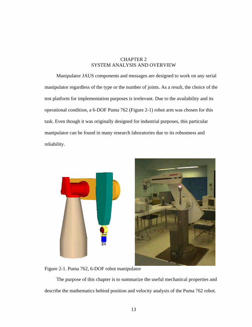
Manipulator JAUS components and messages are designed to work on any ser
manipulator regardless of the type or the number of joints. As a result, the choice o
test platform for implementation purposes is irrelevant. Due to the availability and its
operational condition, a 6-DOF Puma 762 (Figure 2-1) robot arm was chosen for t
task. Even though it was originally design
ial
f the
his
ed for industrial purposes, this particular
o its robustness and
reliability.
manipulator can be found in many research laboratories due t
Figure 2-1. Puma 762, 6-DOF robot manipulator
The purpose of this chapter is to summa seful mechanical properties and
escribe the mathematics be ind
rize the u
d h position and velocity analysis of the Puma 762 robot.
13

14
The theoretical approach and notations used in the following sections specifically follow
defi .
2.1 Mechanism Overview
The Puma arm can be compared to a human torso, shoulder, and wrist. It consists
of members connected by six revolute joints, each defining an axis about which the
members rotate. The major joints are equipped with limit-switch-shutoff-sy
ositioned 2 degrees past the software stops providing additional safety. The Puma 762
weighs 590 kg and has a maximum static payload of 20 kg. Table 2-1 lists useful
Table 2-1. Mechanical specifications of the Puma 762 robot 2 3 4 5 6
nitions outlined by Crane and Duffy [9, 10]
stems
p
mechanical specifications of the system.
Joint # 1 Software Movement Limits (deg) 320 220 270 532 220 532
Joint Angular Resolution (deg * 10-3) 5.0
Encoder Index Resolution; equal to one motor re
4.0 2.78 3.57 6.26 6.26 13.4
3.5 4.5 12.5 6.2 13.4
volution (deg)
tic Analysis of the Puma 762 Robot
2.2.1 Notation
Figures 1-2 and 1-3 show detailed
label revolute and prismatic joints, respectively. The mechanism parameters listed in
Table 2-2 are used to create a kinematic chain shown in Figure 2-2. The proper analysis
of a robot manipulator mandates that a coordinate system is attached to each of the
]. Its
2.2 Kinema
definitions of vectors and parameters used to
bodies. The coordinate system attached to link ij is called the ith coordinate system [9
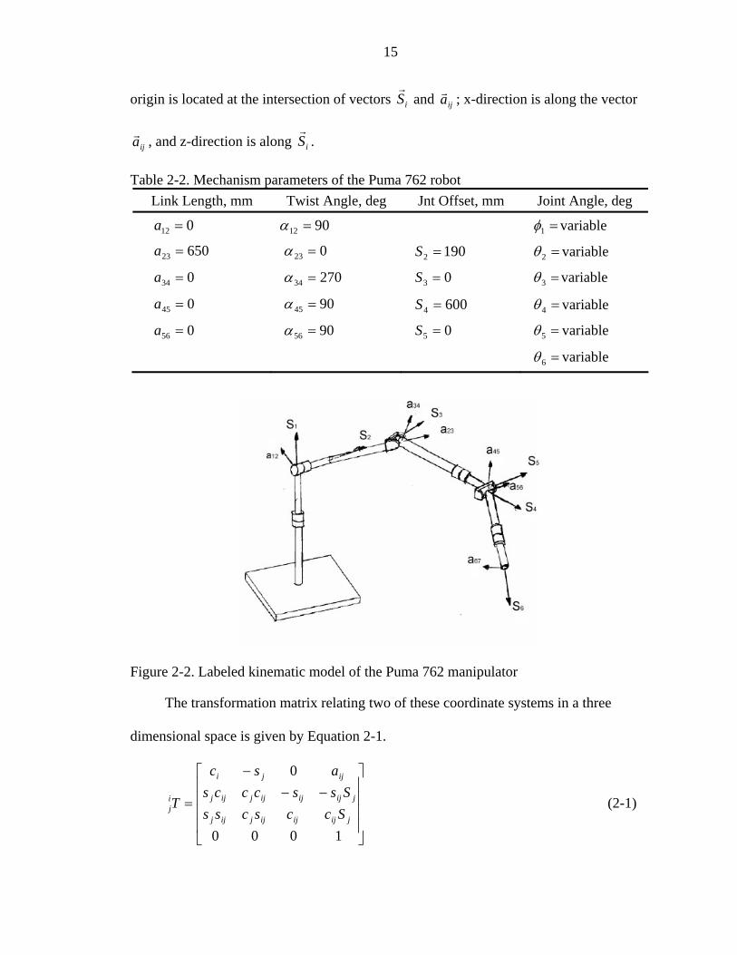
15
origin is located at the intersection of vectors iSr
and ijar ; x-direction is along the vector
ijar , and z-direction is along iSr
.
Table 2Li
-2. Mechanism parameters of the Puma 762 robot nk Length, mm Twist Angle, deg Jnt Offset, mm Joint Angle, deg
012 =a 9012 =α =1φ variable
65023 =a 023 =α 1902 =S =2θ variable
270034 =a 34 =α 03 =S =3θ variable
90045 =a 45 =α 6004 =S =4θ variable
90056 =a 56 =α 05 =S =5θ variable
=6θ variable
Figure 2-2. Labeled kinem
The transformation matrix relating two of these coordinate systems in a three
⎦
⎢
⎣ 1000
jijijijjijji
atic model of the Puma 762 manipulator
dimensional space is given by Equation 2-1.
⎥⎥
⎥⎤
⎢⎢
⎢⎡
−−−
=
0
jijijijjijj
ijji
j SccscssSsscccs
asc
T (2-1) ⎥

16
The inverse of this transformation is very frequently used and is given by the
follow
⎥⎤
⎢⎢⎢⎢
−−
−
=0 jijij
ijjj
ijjijjijj
sccs
acssc
T
or, and represent the sine
ing 4×4 transformation:
⎡ j sc
⎥⎥⎥
⎦⎣
−1000
ijjijjji Sc
assc (2-2)
where ija represents a link length of a serial manipulat is ic
and cosine of iθ , respectively. Furthermore, and represent the sine and cosine ofijs cij ijα .
Finally, a fixed coordinate system is defined as having its origin coincident with the
origin of the first coordinate system and its axis along the vector 1Sr
. The transformation
that relates the first coordinate system and the fixed is given in Equation 2-3.
⎥
⎥
⎦
⎤
⎢
⎢
⎣
⎡ −
=
10000100
00sincos 11
1
φφ
T (2-
General expressions determining the directions of joint vectors with respect to the
first coordinate system are given in Equations 2-4 and 2-5.
⎥
⎥
⎢
⎢ 00cossin 11 φφF 3)
⎦⎢⎢⎣
=101
1S ⎢−= 122 sS ⎥⎥⎥⎤
⎢⎡0
r ⎥⎤
⎢⎡
1
0r
⎥⎦⎢⎣ 12c⎥
⎥⎦⎢⎣ 2Z ⎥⎦⎢⎣ −− 2,...,2,1 nnZ
⎤⎡1 ⎤⎡ 2c ⎤⎡ −− 2,...,1,1 mnW
⎥⎢= 23 YS ⎢= −− 2,...,2,1 nnn YS (2-4)
⎢⎢⎢
⎣
=0012
1ar ⎢
⎣ 122ss
r ⎢
⎣ −− 2,...,1,1 mnU
r
where t
a
⎥⎤
⎢⎡ 2
1
Xr ⎥
⎤⎢⎡ −− 2,...,2,1
1nnX
r
⎥
⎥⎥⎥
⎦ ⎥⎥
⎢⎢= 12223
1 csa ⎥⎥
⎢⎢−= −−
*2,...,1,1
1mnnm Ua (2-5) ⎥
⎦
⎥
⎦
he definitions of the X, Y, Z and W, U*, U are presented in Appendix A. Using
the coordinate transformation given in Equ tion 2-3 and expressions from Equations 2-4

17
and 2-5, direction vectors can be obtained in terms of the fixed coordinate system and are
shown in Equations 2-6 and 2-7.
iF
iF STS
rr1
1⋅=
ijF
ijF aTa
(2-6)
rr 11⋅= (2-7)
2.2.2 or
The most basic problem in the analysis of serial manipulators is to determine the
position and orientation of the end-effector for a specified set of joint angles. Following
the method outlin ines the
transformation that relates the end-effector coordinate system to the fixed coordinate
system. In the case of a 6-axis r
follow :
(2-8)
can be found
fro
(2-9)
All of the terms in Equation mechanism s that
are listed in Table 2-2 for the Puma 762 manipulator.
A mo complicated problem arises when one is trying to determ sible
joint-angle configurations for a specific end-effector position and orientation. This
on-t f
is
e kinematic analysis and begins by closing the link-loop with a
hypothetical member. For a 6-R (6-revolute-joint) manipulator such as the Puma 762, this
F ward and Reverse Position Analysis
ed by Crane and Duffy [9], the first step to the solution determ
obot, the transformation in question is obtained as
s
TTTTTTT FF 56
45
34
23
1216 ⋅⋅⋅⋅⋅=
The coordinates of the end-effector in the fixed coordinate system
m Equation 2-9.
toolF
toolF PTP 6
6 ⋅=
2-8, are obtained from known parameter
re ine all pos
n rivial solution is clearly more difficult, however due to a favorable geometry o
most of the industrial manipulators, much of the analysis is simplified. The approach
referred to as the revers

18
results in a 1-degree-of-freedom 7-R spatial mechanism with the angle 7θ known [9].
Detailed derivation of the solution to this problem is provided by Crane and Duffy [
thus only the final equations used to obtain the values of the 6-close the-loop param
are shown below. The twist angle 71
9],
- eters
α can be calculated using Equations 2-10 and 2-1
1771 SSc FF
1.
rr⋅= (2-10)
( ) 11771 SSSs FFFrrr
⋅×=
Next, joint angle
(2-11)
7θ is found using Equations 2-12 and 2-13.
2) 71677 aac FF rr⋅= (2-1
( ) 7171677 aaas FFF rrr⋅×= (2-13)
eter 1γ is defined as the angle between the vector 71arParam and the x-axis of the fixed
⎤
coordinate system, thus using a similar approach as outlined above, this angle is obtained
using Equations 2-14 and 2-15.
⎦⎢⎣
⎡
0
1r
01
sin Sa FFrr
⋅
⎥⎥
⎢⎢⋅= 0cos 711 aFγ (2-14)⎥
1711
0 ⎟⎟⎟⎞
⎜⎜⎛
⎥⎥⎤
⎢⎢⎡
×=γ (2-15)
⎠⎜⎝ ⎥⎦⎢⎣
Finally, the values of 7S , 71a and 1S can be obtained and are given by Equations 2-16, 2-
17, and 2-18 respectively.
( )71
7 s
F r7161 aPS
S otigFFrr
⋅×= 2-16) (

19
( )71
71671 s
SSPa
FForig
Frrr
⋅×= 2-17) (
( )
711 s
SFFF rr
7176 aSP orig
r⋅×
( 18)
Table 2-3. Closed-loop mechanism parameterLink Length, mm Twist Angle, deg Jnt Offset, mm Joint Angle, deg
= 2-
Table 2-3 shows the mechanism parameters for the newly formed closed-loop spatial
mechanism.
s of the Puma 762 robot
012 =a 9012 =α ..1 LCS = =1φ variable
65023 =a 023 =α 1902 =S =2θ variable
34 0=a 27034 =α 03 =S =3θ variable
90045 =a 45 =α 6004 =S =4θ variable
90056 =a 56 =α 05 =S =5θ variable
067 9067=a =α 1296 =S =6θ variable
..71 LCa = ..71 LC=α ..7 LCS = =7θ C.L.
Once all of the closed-loop parameters have been calculated, the vector-loop
equation for the closed-loop Puma mechanism can be constructed and is represented
using Equations 2-19:
071717171664423232211
rrrrrrrr=++++++
Ex nding these v ctors and exp
aaSSSSSSaaSSSS (2-19)
pa e ressing them in terms of the Set 14 of the table of
direct n cosines fo
⎢⎢⎢
⎣
=⎥⎥⎥
⎦⎢⎢⎢
⎣
+⎥⎥⎥
⎦⎢⎢⎢
⎣
+⎥⎥⎥
⎦⎢⎢⎢
⎣
+⎥⎥⎥
⎦⎢⎢⎢
⎣
+⎥⎥⎥
⎦⎢⎢⎢
⎣
−+⎥⎥⎥
⎦⎢⎢⎢
⎣⎥
⎥
⎦⎢
⎢
⎣ 00
010 1217117716567142232
12 Ucsa
ZYS
ZYS
ZYSsaS
c(2-20)
Further simplification is obtained by using subsidiary spatial and polar-sine, sine-cosine,
and cosine laws from Equation 2-21.
io r the spatial heptagon (Appendix A) results in:
⎤⎡⎤⎡⎤⎡⎤⎡⎤⎡⎤⎡⎤⎡+⎥
⎤
⎢
⎡−
000 117156712
121
cXXXcsS
⎥⎥⎥
⎦121715671

20
⎥⎥⎥
⎦
⎤⎡⎤⎡ 325671 XX
The representation in Equation 2-20 yields three equations. Further substitution of th
⎢⎢⎢
⎣
−=⎥⎥⎥
⎦⎢⎢⎢
⎣ 3
*32
5671
5671
ZX
ZY (2-21)
e
know te n rms and simplification of the Z component of the equation yields Equation 2-22.
[ ] [ ] [ ] 0217176117776 =+++ SsaXSc (2-22)
This is an equation of the form
− sSYS
011 =++ DBsAc , where A, B, and D are constants. The
solution provides two possible values labeled as a1θ and b1θ . Corresponding values of the
ated as )( 11 γθ −a and )( 11 γθ −b . angle 1φ can be calcul
Substituting the known values into the X and Y components of the Equatio 2-20
7117716324223
n
yields Equations 2-23 and 2-24:
01 =++++ c (2-23)
(2-24)
Moving the terms that do not contain the unknown variables and expanding the
direction-cosines results in Equations 2-25 and 2-26:
(2-25)
(2-26)
wher ca
aXSXSXSca
017716*32432342231 =++−+−− YSYSXSVasaS
AsSca =+ +324223
BcSsa =−− +324223
e 17117716 XSXSA −−−= , 177161 YSYSSB −−= , while and represent
sine and cosine of
32+s 32+c
)( 32 θθ + , respectively. Squaring both sides of both Equations 2-25
and 2-26 and then adding them yields Equation 2-27.
(2-27) [ ] 22322322423
24
223 2 BAsccsSaSa +=−++ ++

21
[ ] ( )[ ] ( ) 33swhere 322322322 insin ssccs −=−=+−=− ++ θθθθ . Substituting this term back
into the Equation 2-27 results in Equation 2-28.
[ ] [ ] 02 2224
2234233 =−−++− BASaSas (
This equation contains only 3
2-28)
θ as the unknown. For each value of 1θ , 2 corresponding
values of 3θ are determined. Regrouping Equations 2-25 and 2-26 yields the following
relationships:
[ ] ssSac [ ] AcS =− 34234232 (2-29)
+−
[ ] [ ] BcScsSas =−++− ]34234232
Equations 2-29 and 2-30 provide a system
(2-30)
of 2 equations and 2 unknowns. Thus a unique
value of 2θ is solved for each corresponding set of 1θ and 3θ . The next step is to solve for
5θ us g in Equation 2-31:
57123 ZZ = (2-31)
With corresponding substitutions and expansions, this yields two values of 5θ for each
set of 7θ , 1θ , 3θ , and 5θ as follows:
71235 Zc −= (2-32)
Solution of 4θ is
and 2
)
(2-34)
wher
obtained from a system of 2 subsidiary spherical Equations 2-33
-34.
712354 XX = (2-33
7123*54 YX −=
e 454554 sYcXX −= and 4545*54 cYsXX += . Final form of the solution shown in

22
Equations 2-35 will result in a unique value of 4θ for each of the 8 sets of corresponding
angle values.
5
4 sX
c (7123= 2-35)
5
7123
sY
−=
The solution of the last remaining joint angle 6
4s (2-36)
θ is obtained using the followi
two fundamental spherical sine and sine-cosine laws defined by Equations 2-37 a
ng
nd 2-38.
2-37)
(2-38)
65643217 ssX = (
csY =
Since
65643217
56α 432176 Xs = and 432176 Yc =is known, the equations reduce to . The final solution
tree for the Puma 762 robot is shown below in Figure 2-3.
Figure 2-3. Reverse analysis solution tree for Puma 762 robot

23
2.2.3 Forward and Reverse Velocity Analysis
Similar to the forward position analysis, the velocity analysis assumes that the
angular velocities of each of the joints are known, and as a result it determines the
velocity state of the last link of the manipulator as shown in Equations 2-39.
65655454434332322121606060
6060
60
60
SSSSSSSS
v O
/+/+/+/+/=/=⎥⎦
⎤⎢⎣
⎡=⎥⎦
⎤⎢⎣
⎡ωωωωωωωω
r
r
r
r
ji S/ are the unitized line coordinates for each of the joint-axes. From Duffy and
(2-39)
where
Crane[10], this equation can be rewritten in the matrix format yielding Equation 2-40.
ωωω JSv
=/=⎥⎦
⎢⎣
60 r ⎤⎡ 6060
60 r
(2-40)
atrix, is the 6
×where J, the Jacobian m 6 matrix formed from the unitized screw
655443322110
OOOOOO SSSSSSSSSSSSSS rrrrrr
coordinates, which can be written using Equation 2-41.
[ ] ⎥⎦
⎤⎢⎣
⎡=//////=
655443322110
655443322110
SSSSJrsrrrr
(2-41)
whereω is the vector of joint velocities defined by Equation 2-42.
(2-42)
Assuming that the position analysis is completed, all members of the Jacobian are
known, thus the forward velocity analysis is completed using Equation 2-39. Just as was
the case with the position analysis, the reverse velocity problem becomes more
complicated and individual joint velocities can be determined by simple arithmetic
yielding Equation 2-43.
(2-43)
[ ]T655443322110 ωωωωωωω =
60601 SJ /⋅⋅= − ωω

24
It is possible that the manipulator is driven to a configuration in which the Jacobian
matrix is singular and the inverse cannot be obtained [10]. Such configurations are the
pic of the following section.
2.2.4
h such
conditions occur. Such configurations will cause joint velocities to rapidly increase, and
there will be no feasible solutions of the manipulator to move in a desired direction.
Many computational methods are developed to optimize singularity avoidance.
For practical purposes, the line coordinates of the Jacobian matrix shown in
Equation 2-44 are expressed in terms of the third coordinate system. This is
arithmetically the most favorable selection and allows for easy identification of singular
configurations.
(2-44)
The determinant of this Jacobian yields Equation 2-45.
to
Singularity Determination
A robot is defined to be in a singular configuration when the determinant of the
Jacobian is equal to 0. Duffy and Crane [10] also define this special configuration when 1
or more of the joint-axis lines as defined in the previous section become linearly
dependent to the others. This section identifies those configurations in whic
⎥⎥⎥⎥⎥⎥⎥⎥
⎦
⎤
⎢⎢⎢⎢⎢⎢⎢⎢
⎣
⎡
−−−−
−−−
=
+
+
+
+
45444223
323322
45444323322
454
532
45432
0000000
000110
0100000
csSsScacasS
ssScSsacSssc
cccsss
J
[ ] ( )( )[ ]32422335423det ++−−= sScacsSaJ (2-45)
The left side of the Equation 2-45 equals zero if:
• Wrist singularity (s5 = 0): In this case vectors and become collinear. 4S 6S
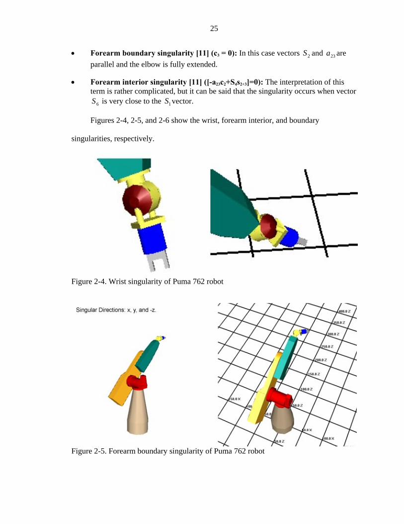
25
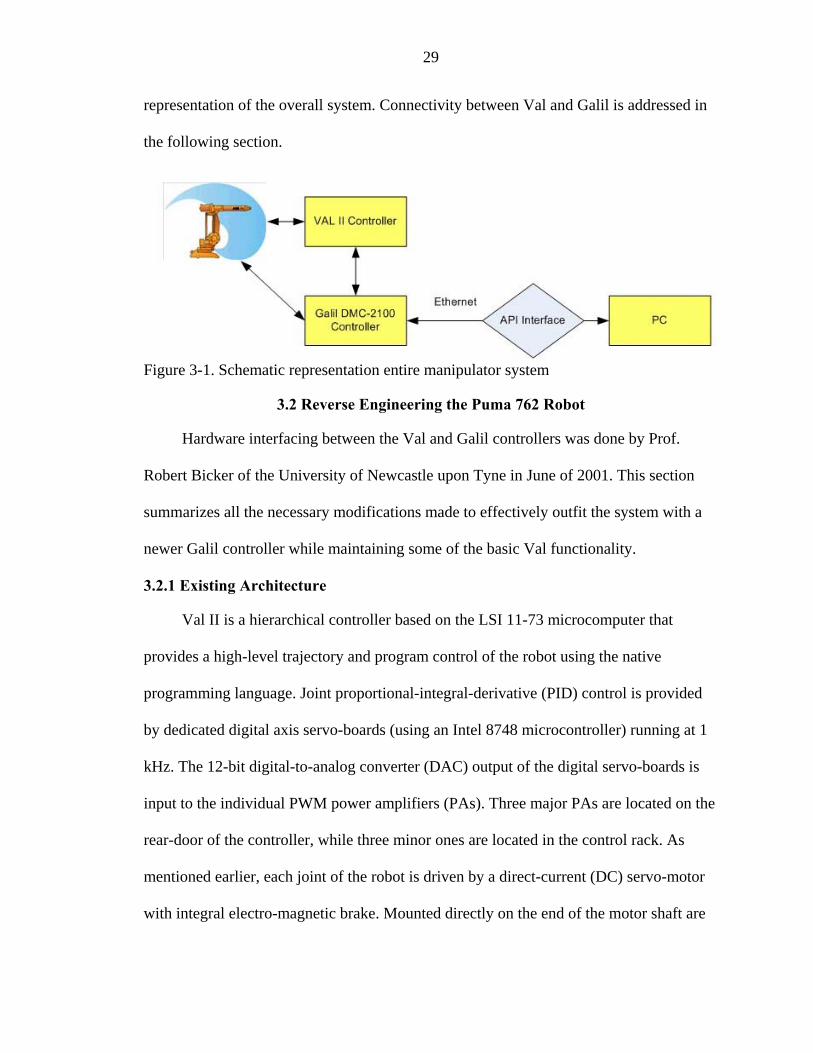
• Forearm boundary singularity [11] (c3 = 0): In this case vectors and are parallel and the elbow is fully extended.
• Forearm interior singularity [11] ([-a23c2+S4s2+3]=0): The interpretation of this term is rather complicated, but i at the singularity occurs when vector
is very close to
2S 23a
t can be said th the 1S vector. 6S
Figures 2-4, 2-5, and 2-6 show the wrist, forearm interior, and boundary
singularities, respectively.
Figure 2-4. Wrist singularity of Puma
762 robot
Figure 2-5. Forearm boundary singularity of Puma 762 robot

26
Figure 2-6. Forearm interior singularity of Puma 762 robot
erest
he
The above 3 configurations require special attention and will be a matter of int
in the upcoming chapters.
2.3.5 Quaternion Representations
Crane and Duffy [9] define a real quaternion as a set of 4 real numbers written in
definite order as shown in Equation 2-46.
),,,( cbadq = (2-46)
Chapter 6 will use quaternion representation for the position and orientation of t
end-effector. For that reason, this section defines those aspects of the quaternion algebra.
The unit quaternion q is defined in Equation 2-47.
( )ksjsisq zyx +++= θθ sin)cos( (2-47)
The equivalent rotation matrix is defined by Crane and Duffy [9] as the following:
⎢⎢
⎡
−+−−−−+−+−
+−−−+−=
θθθθθθθθθθθθθθ
2cos1(2sin)2cos1(2sin)2cos1(2cos1(2cos)2cos1(2sin)2cos1(
sin)2cos1(2sin)2cos1(2cos)2cos1(
2
2
zyyzyx
yzxzyxx
j
sssssssssssss
sssssssR
⎢
⎣ + θθθθ
2cos)2sin_)2
2
zxzyyzx
xi s
⎥⎥⎥
⎦
⎤

27
In summary, this chapter provides all the necessary analysis sufficient for tasks
mand
7.
ated by the proposed JAUS components. Equations derived in Sections 2.3.3 and
2.3.4 will become essential for component development outlined in Chapters 5, 6 and
Detailed information on theory covered in this chapter and more advanced robot
manipulator analysis is presented by Crane and Duffy [9] and Duffy [10].

CHAPTER 3PUMA 762 CONTROLLER SYSTEM
hapter resses the capa of an onboard controller system and ties
t qui ents outlined b AUS C mpliance Specification (JCS)
d fore m dular architectu lementation, the platform was in operational
c allowing user to contro tion of the individual joints using
commercially available software. Such conditions required no additional changes to the
c rdware configuration. For c etion pur chapter provides a brief
s f modifi ons to the orig em configuration. Further emphasis is put
on the functions available in the C/C ication terface (API) and its
u implementation.
verview
ve to the a 762 is the V h lev anguage. Aside from
being a sophisticated development to plete control system. Joint
A n stems standard currently dictates the use of a C
progr
This c add bilities
hem into the re rem y the J o
ocument. Be o re imp
ondition, the l the mo
urrent ha ompl poses, this
ummary o cati inal syst
++ Appl Programming In
se in this
3.1 O
Nati Pum al II hig el programming l
ol, Val II is a com
rchitecture for U manned Sy
amming language for development purposes. Due to some deficiencies in the older
VAL controller and lack of an adequate API, the Puma was outfitted with a Galil DMC-
2100 motion controller. Unfortunately, the use of a commercially available motion
controller dictates operational constraints. The JCS document mentioned above defines
three levels of interoperability. This implementation satisfies inter-nodal, or level II
compliance, supporting interoperation between nodes [12]. Figure 3-1 shows the simplest
28
29
representation of the overall system. Connectivity between Val and Galil is addressed in
the following section.
Figure 3-1. Schematic representation entire manipulator system
3.2 Reverse Engineering the Puma 762 Robot
microcomputer that
d program control of the robot using the native
p ngu Joi po al-integral-derivative (PID) control is provided
by dedicated digital axis ser ard sing an Intel 8748 microcontroller) running at 1
kHz. The 12-bit digital-to-analog converter (DAC) output of the digital servo-boards is
input to the individual PWM power a ajor PAs are located on the
rear-door of the controller, while three minor ones are located in the control rack. As
menti otor
e end of the motor shaft are
Hardware interfacing between the Val and Galil controllers was done by Prof.
Robert Bicker of the University of Newcastle upon Tyne in June of 2001. This section
summarizes all the necessary modifications made to effectively outfit the system with a
newer Galil controller while maintaining some of the basic Val functionality.
3.2.1 Existing Architecture
Val II is a hierarchical controller based on the LSI 11-73
provides a high-level trajectory an
rogramming la age. nt pro rtion
vo-bo s (u
mplifiers (PAs). Three m
oned earlier, each joint of the robot is driven by a direct-current (DC) servo-m
with integral electro-magnetic brake. Mounted directly on th

30
an incremental encoder (25 eter providing position
feedb
hen
nector located in the J56 slot directs encoder quadrature (A &
Q), in
ure
0 lines) and a geared servo-potentiom
ack. The initial calibration process requires each joint to be driven through a small
angle, sufficient to locate the nearest encoder index. This non-absolute position is t
compared to the values stored in a look-up table via the corresponding analog
potentiometer reading [13].
3.2.2 Encoder and Potentiometer Val Interface
The board edge con
dex and potentiometer outputs to respective digital servo-boards (J45-50) via a
J-bus backplane. Wire-wrap terminals are provided at the rear of the backplane only on
the J56, and wire-wrap connections are made to a 50-way IDC wire-wrap connector. A
50-way ribbon cable runs to a break-out box, and then single core cables are bundled to
the respective connections on the Galil ICM-2900 modules, designated 1 and 2 (Fig
3-2).
Figure 3-2. Arm signal interconnects between Val and ICM-2900 modules

31
3.2 Amplifier Digital-to-An.3 alog Converter Signals and Control Lines
l
ines are also present. Table 3-1 shows the pin
connections between the Val controller and Galil’s interconnect modules.
Table 3-1. Pin connections between Val and Galil ICM-2900 interconnect modules VAL Signal 34/50 way pin Wire color ICM-2900
The DAC outputs on the Val controller for each axis are derived by the digita
servo boards. The DAC (+/-) signals are presented to a 34-way IDC connector on the
control backplane, and are linked to the power amplifier backplane via a 34-way ribbon
cable (J103 => J79). Additional control l
_teach-error 1 white _stop 2 white 1/14/INPUT1 Hnd-sig1 3 white Hnd-sig2 4 white Brk-on-hi 5 white
E-sto_ox-inhibit 8 white 1/14/INPUT3
DAC-1 12 blue 1/3/GND
blue 1/4/GND DAC+3 15 orange 1/1/MOCMDZ DAC-3 DACDAC-4 18 blue 1/1/GND
DAC+6 21 orange 1/4/MOCMDY
_Encoder fault 34 white 1/14/INPUT2
Deadman-sw 6 white p b 7 white
Servo E-stop 9 white DAC+1 11 orange 1/3/MOCMDX
DAC+2 13 orange 1/4/MOCMDY DAC-2 14
16 blue 1/1/GND +4 17 orange 1/2/MOCMDW
DAC+5 19 orange 2/3/MOCMDX DAC-5 20 blue 2/3/GND
DAC-6 22 blue 1/4/GND Remote +ve 33 white

32
In order to retain Val safety functionality, all control lines are connected straight
0-34 interconnection cabling. Stop, Encoder-fault and Ox-inhibit
pectively of the ICM module 1. The amplifier
ed by a single control line BRK-ON-HI (brake on high). This is a
TTL controller, which is pulled low on VAL being
initia o drive this line
low v
through via the 34-50-5
signals are linked to digital inputs 1-3, res
enable signal is provid
open-collector output from the LSI-11
lized. A 7406 hex-inverter (with open-collector outputs) is used t
ia the Galil digital output 1 as is shown in Figure 3-3.
Figure 3-3. BRK-ON-HI connection diagram
using the Galil
comm mote ON/OFF switch
box ( e arm
essential to apply either the SH or
orOff) Galil commands prior to powering up the arm to prevent any
ck mode (AFn=1). Step response tests
ere carried out using the Servo-Design Kit software. Small and large steps (100 and
3.2.4 Safety
fiers are enabled by pulling-low BRK-ON-HIThe power ampli
and OP1 (OutPut 1 set). Arm power is applied using the re
if motion control set to REMOTE) or via the front panel (if set to LOCAL). Th
will attempt to go into closed loop at this time, and it is
MO (ServoHere, Mot
run-away.
3.2.5 Tuning
Axis tuning was carried out sequentially, initially in the digital feedback mode
(AFn=0), and subsequently in the analog feedba
w

33
1000 counts – using encoder feedback) as well as manual tuning and auto-tuning features
were used, although manual tuning was preferred. Proportional (KPn), Derivative (KDn)
and Integral action gains (KIn) are set as shown in Table 3-2.
Table 3-2. CoAxi
ntroller gain values s/Joint # KP KD KI
A/1 80 500 1 B/2 60 500 1 C/3 100 200 1 D/4 100 500 1 E/5 100 500 1 F/6 100 500 1
Once adequately t endly computer
interf
res including high-speed communications, non-volatile
d improved cabling for noise reduction. It is
desig ctor
ommand motion using the Galil controller. The
requir
f the
lute or relative position and selects the values of
maxim
uned, this configuration provides a user fri
ace and allows for simple control of the manipulator.
3.3 Galil DMC-2100 Functionality
DMC-2100 is one of Galil’s highest performance stand-alone controllers outfitted
with many enhanced featu
program memory, faster encoder speeds an
ned to solve complex problems involving jogging, point-to-point positioning, ve
positioning, electronic gearing, multiple move sequences, and contouring [14].
3.3.1 Command Modes
There are several of ways to c
ements of this project are simple and only take advantage of two motion modes.
Independent axis positioning generates an independent trajectory profile for each o
axes. The user commands either abso
um speed, acceleration and deceleration. The second, and more relevant, is
independent jogging. This mode is very flexible and allows the user to change all of the

34
above-mentioned values during motion and specify the direction. The controller operates
as a closed-loop position con
troller while in the jog mode. It converts the velocity profile
et is generated with every sample period
[14].
ee
ming.
servo system. On the lowest level, the
contro
into a position trajectory and a new position targ
3.3.2 Theory of Operation
This section only offers a brief overview of the operation of a motion control
system. Detailed information can be found in many control theory books and controller
manuals. The operation of a system (such as the DMC-2100) could be divided in thr
levels as follows:
• Closing the loop
• Motion profiling
• Motion program
Figure 3-4 shows the elements of the
ller ensures that the motor follows the commanded position. This is accomplished
using a feedback provided by a sensor. In the case of the Puma system, position feedback
is provided by an incremental encoder.
Figure 3-4. Functional elements of a motion control system
Most of the commercially available motion controllers use trajectory generators.
This function describes where the motor should be at every sampling period. Finally, at

35
the highest level of control, the program describes the tasks such as desired distances or
speed [14]. A detailed mathematical model of each of the various components presented
below can be found in [14].
3.4 Galil C/C++ Application Programming Interface (API)
Engineers at
Galil Motion Control Inc. have developed a set of API function calls
evelopment on various computer platforms. These calls
provi
res
is section lists only the calls and
es used in our study (Figure 3-5 through 3-9). Additional function
ned in the interface document [15].
extern LONG FAR GALILCALL DMCInitLibrary(void);
that can be used in software d
de an effective link between the Galil machine code and standard C or C++
programming languages. Manipulator JAUS implementation more specifically requi
libraries running on the Linux operating system. Th
corresponding prototyp
calls and installation procedures are outli
Function Prototype:
Function Description: This function must be called prior to using the library.
Figure 3-5. Initializing the Galil libraries
Function Prototype: extern LONG FAR GALILCALL DMCOpen(PCONTROLLERINFO pcontrollerinfo, PHANDLE phdmc);
Function Description: The handle to the controller is returned in the argument phdmc. Pcontrollerinfo: Structure holding information about the controller. Phdmc: Buffer to recelive the to the Galil controller to be used in all subsequcalls.
ent
Figure 3-6. Establishing communications with the Galil Controller
Function Prototype: extern LONG FAR GALILCALL DMCClose(HANDLEDMC hdmc);
Function Description: This function closes the Ethernet connection to the controller.
Figure 3-7. Closing the connection to the Galil Controller

36
Function Prototype:
pszCommand, PCHAR pchResponse, ULONG cbResponse); extern LONG FAR GALILCALL DMCCommand(HANDLEDMC hdmc, PSZ
Function Description:
pchResponse: Buffer receiving the response data.
This function is used to send commands to the controller.
pszCommand: The command send to the controller in the machine language.
cbResponse: Length of the buffer. Figure 3-8. Sending commands to the Galil Controller
extern LONG FAR GALILCALL DMCReset(HANDLEMC hdmc); Function Prototype:
Function Description: This function is used to reset the controller.
Figure 3-9. Resetting the controller
The use of these calls will become more apparent in Chapter 9 as the aspects of
software design on a node level are introduced.

CHAPTER 4 COMPONENT
s the latest
Reference Architecture Document. The
chapt
9) allows for low-level command
f the manipulator joint efforts. This is an open-loop command that could be used in a
simple tele-operated scenario. This component is currently in version 3.2 of the JAUS
Reference Architecture.
4.1.1 Definition of Coordinate Systems
A variety of platform configurations on which manipulator components can be
implemented might require data to be interpreted in terms of different coordinate systems
either to adequately define the geometry or allow for easier task completion.
4.1.1.1 Global coordinate system
Points that are defined in this coordinate system are defined in units of longitude,
latitude, and elevation. The x-axis points North and the z-axis points downward.
4.1.1.2 Vehicle coordinate system
This coordinate system is attached to the vehicle frame. The x-axis points in the
forward direction and the z-axis points downward. The y-axis is defined so as to have a
LOW-LEVEL MANIPULATOR CONTROL
This chapter defines the Primitive Manipulator (PM) component in terms of the
JAUS architecture. For the purposes of easy insertion, the format used to present the
information in the first section of this and the upcoming chapters, follow
format outlined in version 3.2 of the JAUS
er further details the application of the PM to the Puma system.
4.1 Primitive Manipulator Component
The one component in this category (JAUS ID# 4
o
37
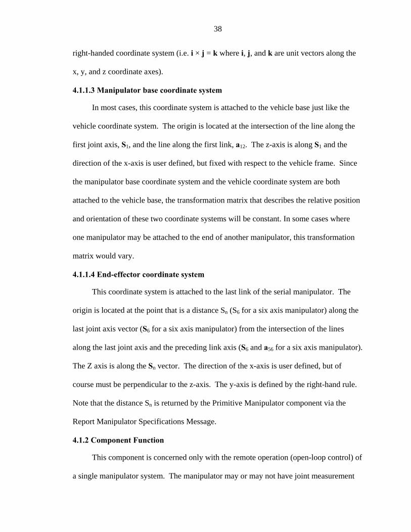
38
right-handed coordinate system (i.e. i × j = k where i, j, and k are unit vectors along the
x, y, and z coordinate axes).
4.1. Ma base co ate system
In most cases, this coordinate system is attached to e the
vehicle coordinate system. The origin is loc t the inter line along the
first joint a d the line first 12. The z-axis is along S1 and the
direction of the x-axis is user defined, but fixed with respect to the vehicle frame. Since
the nipula ordina nd the vehicle coordinate system are both
attached to the vehicle base, the transformation matrix that d position
and orienta ese two c syste e co here
one manipulator may be attached to the end of another ma tion
matrix would vary.
4.1.1.4 End-effector coordinate system
This coordinate system is attached to the last link of r. The
origin is located at the point that is a distance Sn (S6 for a ng the
last joint ax r a manipulator) from the
along the last joint axis and the preceding link axis (S6 and a56 for a six axis manipulator).
The Z axis is along the Sn vector. The direction of the x-axis is user defined, but of
course must be perpendicular to the z-axis. The y-axis is de .
Note that the distance Sn is returned by the Primitive Man the
Report Manipulator Specifications Message.
4.1.2 Component Function
This component is concerned only with the remote operation (open-loop control) of
a single manipulator system. The manipulator may or ma not have joint measurement
1.3 nipulator ordin
the vehicle base just lik
ated a section of the
xis, S1, an along the link, a
ma tor base co te system a
escribes the relative
tion of th oordinate ms will b nstant. In some
a
cases w
nipulator, this transform
the serial manipulato
six axis manipulator) alo
intersection of the lines is vector (S6 fo six axis
fined by the right-hand rule
ipulator component via
y

39
sensors that would provide joint position and joint velocity information. Without joint
measurem ope n only oint mo mands to the
manipulat nen t use a int angle or velocity feedback from the
ma lato eives sired percentage of m ch
joi an
4.1.3 Associated Messages
The PM accepts the core input and output ssages listed in Table 1-1. The set of
user defined input and output m s specifi his co elow.
Detailed definitions are provid tion 4
• et Jo
•
• Query Joint Efforts
• epo pe tions
• po
m riptio
This the lo nterface to a mani is in many
respects similar to the Primitive r component for mobility of the platform. When
q the will r des of th cification
p ers f motion, and axes velocity limits. The notations used to
describe these data are docum any popular text books on robotics and were
previously presented in Chapter 2. The mechanism specification parameters as reported
y the Report Manipulator Specifications Message consist of the number of joints, the
pe of each joint (either revolute or prismatic), the link description parameters for each
nk (link length and twist angle, Figures 1-1 to 1-3), the constant joint parameter value
ent sensors, the rator ca send j tion efforts as com
or. This compo t does no ny jo
nipu r. It only rec the de aximum joint effort for ea
nt as input.
me
c to tessage mponent are listed b
ed in Sec .2.6.
S int Effort
Query Manipulator Specifications
R rt Manipulator S cifica
Re rt Joint Efforts
4.1.4 Co ponent Desc n
component is w-level i
Drive
pulator arm and
ueried, component eply with a cription e manipulator’s spe
aramet , axes range o
ented in m
b
ty
li

40
(offset for a r hapter 1,
Figur
evolute joint, Figure 1-2), and joint angle for a prismatic joint (C
e 1-3). The minimum and maximum allowable value for each joint and the
maximum velocity for each joint follow this information. Motion of the arm is
accomplished via the Set Joint Effort message (Figure 4-1). In this message, each
actuator is commanded to move with a percentage of maximum effort.
Primitive Manipulator
Commanded joint effort
This section provides detailed specifications of user defined messages. It covers
data types used for each of the parameters, as well as the upper and lower lim
Actuator commands
Figure 4-1. Joint effort provides basic manipulator mobility
4.1.5 Input and Output Messages
its. This
information becomes very important for software development purposes and is further
covered in Chapter 8.
4.1.5.1 Code 0601h: Set Joint Effort
Field #1 in Table 4-1 indicates the number of joint effort commands contained in
this message. This message sets the desired joint effort values.
Table 4-1. Set Joint Effort message parameters Field # Name Type Units Interpretation
1 Num Joints Byte N/A 1 ... 255; 0 is Reserved
2 Joint 1 –effort Short int Percent Scaled integer Lower Limit = -100% Upper Limit = +100%
3 ... n … n + 1 Joint n –effort Short int Percent see field 2

41
4.1.5.2 Code 2600h: Query Manipulator Specifications
This message shall cause the Primitive Manipulator component to reply to the
requestor with a Code 4600h: Report Manipulator Specifications message.
4.1.5.3 Code 2601h: Query Joint Effort
This message shall cause the receiving component to reply to the requestor with a
Code 4601h: Report Joint Efforts message.
4.1.5.4 Code 4600h: Report Manipulator Specifications
This message provides the specifications of the manipulator including the number
of joints, the link lengths, twist angles, offset or joint angles, minimum and maximum
value for each joint, and minimum and maximum speed for each joint.
4.1.5.5 Code 4601h: Report Joint Effort
This message provides the receiver with the current values of the commanded joint
effort. The message data and mapping of the presence vector for the Report Joint Efforts
message are identical to Code 0601h: Set Joint Effort.

42
Table 4-2. Report Manipulator Specifications parameters Field # Name Type Units Interpretation
1 Number of Joints Byte N/A
1 … 255 0 is Reserved For a value of n the messadata area size in bytes is:
ge
(36 + 13(n-1)) bytes.
2 Joint n Type Byte N/A Joint type of the last joint of the
manipulator. 1 = revolute, 2 = prismatic
3 Joint n –
Offset/Joint Angle
rad omm
Prismatic joint, × 10-3 radians.
Revolute joint, mm
4 Joint n – Min value
5 Joint n – Unsigned
Short rad or
mm
Prismatic joint, mm Revolute joint,
value × 10-3 radians.
Joint n – Unsigned
rad/s or mm/s
Prismatic joint, mm/sec Revolute joint,
value × 10-3 radians/sec.
7 coordinate Integer m
manipulator coordinate
Scaled integer: Lower limit = -30 m Upper limit = +30 m
8 coordinate sys. y
Integer m
y coordinate of origin of
system measured with respect to vehicle coordinate system
9 lator
sys. z Integer m
z coordinate of origin of coordinate
measured with respect ordinate system
10 d component of unit quaternion q Integer N/A
nes the ulator ured cle
it = +1
Unsigned Short
r value
Max value
6 Max velocity Short
manipulator
sys. x
x coordinate of origin of
system measured with respect to vehicle coordinate system
manipulator manipulator coordinate
manipucoordinate
manipulatorsystemto vehicle co
quaternion q defi
orientation of the manipcoordinate system meas
e vehiwith respect to thcoordinate system
Scaled integer: Lower limit = -1 Upper lim

43
Table 4-2. Continued Field # Name Type Units Interpretation
12 see field 10 b component of unit quaternion q
Integer N/A
13 /A see field 10
1 = revolute, 2 = prismatic
14 Link Length Short
Twist Angle Short value × 10-3 radians
14c 1 –
Offset/Joint Angl
Unsigned rad or Prismatic joint,
value × 10-3 radians. m
14e Max value
Unsigned rad or Prismatic joint, mm
14f Short mm/s
Prismatic joint, mm/sec Revolute joint,
value × 10-3 radians/sec. … n-1
)b Link a(n-1)n – Twist Angle
Unsigned Short rad Twist Angle -
value × 10-3 radians
(n-1)c Offset/Joint Unsigned Short
rad or mm
Prismatic joint, value × 10-3 radians.
Revolute joint, mm
(n-1
mm
Prismatic joint, mm Revolute joint,
value × 10-3 radians.
(n-1)f rad/s Revolute joint,
c component of Integer Nunit quaternion q
14 Joint 1 Type Byte N/A
a Link a12 – Unsigned mm Link Length
14b Link a12 – Unsigned rad Twist Angle -
Joint
e Short mm Revolute joint, m
14d Joint 1 – Min value
Joint 1 – Short mm Revolute joint, value × 10-3 radians.
Joint 1 – Unsigned rad/s or Max velocity
Joint (n-1) Type Byte N/A 1 = revolute, 2 = prismatic
(n-1)a Link a(n-1)n – Link Length
Unsigned Short mm Link Length
(n-1
Joint (n-1) –
Angle
)d Joint (n-1) – Min value Unsigned rad or
(n-1)e Joint (n-1) – Max value
Short
Joint (n-1) – Max velocity
Unsigned Short
Prismatic joint, mm/sec
value × 10-3 radians/sec.

44
4.2 Primitive Manipulator Applications to the Puma system
ponent is to allow for tele-op
comm
. Thus, a Set Joint Effort message commanding values of [50, 50,
ts at fifty percent of the maximum
velocity in the positive direction th interpretatio efforts can vary
d nding co ller prov the es that no
sensor feedback is provided, it is possible to drive the robot
triggering a fatal Val II error. Either one of the joints reachi
driving a m ulator to a singular configuration would cause Val to respond in such a
way. In order to prevent this from happening during the tasks requiring closed-loop
board position ad velocity sensor
components covered in the following chapter.
As mentioned earlier, the primary function of this com
ands of joint efforts. This implementation interprets joint efforts as the percentages
of maximum velocity
50, 50, 50, 50] would in effect rotate each of the join
. Note at the n of joint
epe on the type of the ntro ided. Since component assum
into an unfavorable state
ng a hardware limit, or
anip
control, this implementation takes advantage of the on
Computer logic and software design of this
and all other components will be the topic of Chapter 8.

CHAPTER 5
mponents that when queried, return instantaneous joint
siti ue information. Note that a particular manipulator
urement sensors onboard. Consequently, the
imple
e
oint Position Sensor Component
en queried.
1,
ssages specific to this component
• Query Joint Positions
• Report Joint Positions.
Detailed definitions are provided in Section 5.1.4.
MANIPULATOR SENSOR COMPONENTS
This chapter describes the co
po on, velocity, and force or torq
might only have one or two meas
mentation of all three components covered in this chapter is seldom necessary.
Moreover, the JAUS Reference Architecture is not concerned with the type of the sensors
used, but rather with the format in which the measured information is exchanged with th
component requesting it.
5.1 Manipulator J
5.1.1 Component Function
The function of the Manipulator Joint Position Sensor Component (MJPS) is to
report the values of manipulator joint parameters wh
5.1.2 Associated Messages
The MJPS (JAUS ID# 51) accepts the core input and output messages (Chapter
Table 1-1). The set of user defined input and output me
are:
45

46
5.1.3 Component Description
The Report Joint Positions m ssage provides instan ions. The
positions are given in radians for revolute and in meters for p
component is shown in Figure 5-1.
e the taneous joint posit
rismatic joints. The
Joint PositionSensor
actualRepo
join tions ;rt Jo sitions
Message
t posiint Po
requestQuery J
joint pooint Posi
Message
5.1.4.
sitions ;tions
Figure 5-1. Joint position sensor component
5.1.4 Input and Output Messages
Similar to Section 4.1.5, this section and Sections 5.2.4 and 5.3.4, are used to
provide detailed specifications of user defined messages. They cover data types and value
limits for each of the parameters.
1 Code 0602h: Set Joint Positions message
Set Joint Positions message is not defined by this component but it is included as a
reference.
Table 5-1. Set Joint Positions message parametersField # Name Type Units Interpretation
1 Number of Joints Byte N/A 1 ... 255 0 is Reserved
2 Joint 1 –position Int rad or m Scaled integer: If revolute joint, Lower limit = -8π rad Upper limit = +8π rad If prismatic joint, Lower limit = -10 m Upper limit = +10 m
3 ... n … n + 1 Joint n –position Int rad or m see field 2

47
5.1.4.2 Code 2602h: Query Joint Positions message
This message shall cause the receiving component to reply to the requestor with a
Code 4602h: Report Joint Positions message.
5.1.4.3
This message provides the receiver with the current values of the joint positions.
The message data for the Report Joint Positions message is identical to Code 0602h: Set
Joint Positions.
5.2 Manipulator Joint Velocity Sensor Component
5.2.1 Component Function
The function of the Manipulator Joint Velocity Sensor (MJVS) is to report the
values of instantaneous joint velocities when queried.
5.2.2 Associated Messages
The MJVS (JAUS ID# 52) accepts the core input and output messages (Chapter 1,
Table 1-1). The set of user defined input and output messages specific to this component
are:
• Query Joint Velocities
• Report Joint Velocities.
Detailed definitions are provided in Section 5.2.4.
5.2.3 Component Description
The Report Joint Velocities message provides the instantaneous joint velocities.
The velocities are given in radians/sec for revolute and in meters/sec for prismatic joints.
The component is depicted in Figure 5-2.
Code 4602h: Report Joint Positions message

48
actual ivelocit
nstantaneous jointies ;
es MessageReport Joint Velociti
Joint VelocitySensor
request instantaneous jointvelocities ;Query Joint Velocities Message
5.2.4 Input and Output Messages
5.2.4.1 Code 0603h: Set Joint Velocities message
Set Joint Velocities message is not defined t it is included for
reference purposes.
Table 5-2. Set Joint Velocities message parameters Field # Name Type Units Interpretation
Figure 5-2. Joint velocity sensor component
by this component bu
1 Num Joints /A 255 Byte N 1 ... 0 is Reserved
2 Joint 1 –velocity int rm/sec
lute joint, Lower limit = -10π rad/sec Upper limit = +10π rad/sec If prismatic joint,
-5 m/sec /sec
n + 1 Joint n –velocity int rad/sec or see field 2
ad/sec or If revo
Lower limit = Upper limit = +5 m
3 ... n …
m/sec
This message shall cause the receiving component to reply to the requestor with a
Code 4603h: Report Joint Velocities m
This message provides the receiver with the current values of the joint velocities.
The message data for the Report Joint Velocities message is identical to Code 0603h: Set
Joint Velocities.
5.2.4.2 Code 2603h: Query Joint Velocities message
essage.
5.2.4.3 Code 4603h: Report Joint Velocities message
49
5.3 Manipulator Joint Force/Torque Sensor Component
.1 ion
nt Force/Torque Sensor (MJFTS) is to report
torques (for revolute joints) and forces (for prismatic joints)
t a ual joints of the manipulator kinematic model when queried.
.2 ages
ID# 53) accepts the core input and output messages (Chapter 1,
d input and output messages specific to this component
are lis
ntaneous joint forces
or torques acting on each joint of the manipulator kinematic model. Forces are returned
for prismatic joints in units of Newton’s (N). Torques is returned for revolute joints in
units of Newton-meters (Nm).
5.3.4 Input and Output Messages
5.3.4.1 Code 2605: Query Joint Force/Torques
This message shall cause the receiving component to reply to the requestor with a
Code 4605h: Report Joint Force/Torques message.
5.3.4.2 Code 4605h: Report Joint Force/Torques
This message replies to the requestor with the values of current joint forces or
to r p c and revolute joints, r iv
5.3 Component Funct
The function of the Manipulator Joi
the values of instantaneous
tha re applied at the individ
5.3 Associated Mess
The MJFTS (JAUS
Table 1-1). The set of user define
ted below, while detailed definitions are provided in Section 5.3.4:
• Query Joint Force/Torques
• Report Joint Force/Torques
5.3.3 Component Description
The Joint Force/Torque Sensor component provides the insta
rques fo rismati espect ely.

50
Table 5-3. Report Joint Force/Torque message parameters Field # Name Type Units Interpretation 1 N 1
0 is Reserved um Joints Byte N/A ... 255
2 Joint 1 –force or int N or Nm If revolute joint Scaled integer: Lower limit = -1000 Nm
00 Nm If prismatic joint
Lower limit = -500 N
3 ... n …
torque
torque
Upper limit = +10
Scaled integer:
Upper limit = +500 N
n + 1 Joint n –force or int N or Nm see field 2
5.4 Sensor Component Applications to the Puma System
ch nboard the Puma 762 manipu es rem for
position feedback (Chapter 3, Section 3.2.1). This information is o
controller i verted to r s. S arly y is
re rted in ver nto r s p et
JAUS specifications. In many instances, the joint data is converted back to either encoder
c ts or d l int ti
The position sensor component implemented on the Puma system has additional
monitoring joint movement and assuring that
no set software limits have been breached. It further uses the acquired information to
monitor joint angle values approaching singularity configurations (Chapter 2, Section
2.3.4). Actions taken if either occurs are discussed in Chapter 8. The use of MJPS and
MJVS components will become more apparent in the next chapter dealing with
closed-loop control of joint positions and velocities.
Ea joint o lator us an inc ental encoder
btained from the Galil
n encoder counts and is con adian imil , the velocit
po encoder counts per second and con ted i adian er second to me
oun egrees for the purposes of more meaningfu erpreta on.
functionality (Section 5.1.1). This involves

CHAPTER 6 VEL POSITION AND VELOCITY DRIVER COMPONENTS
These components take as inputs the desired joint positions or velocities, or the
desired end-effector pose or velocity state. They further use platform specific information
provided by the PM component, as well as the sensor information obtained from the
MJPS and MJVS components to perform closed-loop position and velocity control. It
should be noted that in most implementations, these components and the Primitive
Manipulator component would be embedded in the same node that will facilitate the
control process. The implementation of the low level drivers to the Puma platform
becomes nontrivial and is addressed in Section 6.5.
river Component
6.1.1 Component Function
The function of the Manipulator Joint Positions Driver (MJPD) is to perform
closed-loop joint position control.
6.1.2 Associated Messages
The MJPD (JAUS ID# 54) accepts the core input and output messages (Chapter 1,
Table 1-1). User defined messages that are received or sent by this component were
defined in previous chapters and are:
• Set Joint Positions
• Report Manipulator Specifications
• Report Joint Efforts
MANIPULATOR LOW-LE
6.1 Manipulator Joint Positions D
51

52
• Report Joint Positions
• Set Joint Effort.
6.1.3 Component Description
The inputs are the desired joint values, current joint angles, and the manipulator
specifications report. The output is the join effort level that is sent to the Primitive
Manipulator component. Figure 6-1 shows the MJPD component.
t
Manipulator JointPositions Driver
Joint PositionSensor
Set Joint EffortMessage
commanded joint values ;Set Joint Positions Message
Report ManipulatorSpecifications Message
PositionsMessage
Report Joint
actual joint effort ;Report Joint Effort Message
Figure 6-1. Manipulator Joint Positions Driver component
6.2 Manipulator End-Effector Pose Driver Component
6.2.1 Component Function
The function of the Manipulator End-Effector Pose Driver (MEEPD) is to perform
closed-loop position and orientation control of the end-effector.
6.2.2 Associated Messages
ts the core input and output messages (Chapter
1, Table 1-1). Some of the user defined messages that are received or sent by this
component were defined in previous chapters, while others are defined in Section 6.2.4.
The following messages are associated with this component:
• Set Tool Point
The MEEPD (JAUS ID# 55) accep

53
• Set End-Effector Pose
•
fort
• Report Tool Point.
ation control of the end-
effector. The input is the desired position and orientation of the end-effector specified in
Query Tool Point
• Report Manipulator Specifications
• Report Joint Efforts
• Report Joint Positions
• Set Joint Ef
6.2.3 Component Description
This component performs closed-loop position and orient
the vehicle coordinate system, the current joint angles, and the data from the manipulator
specification report. The output is the joint effort level that is sent to the Primitive
Manipulator component. The component is shown in Figure 6-2.
Manipulator End-Effector Pose
Driver
Joint PositionSensor
Set Joint Effort
commanded end effector pose ;Set End Effector Pose Message
MessageReport ManipulatorSpecifications Message
Report JointPositionsMessage
actual joint effort ;Report Joint Effort Message
6.2.4 Input and Output Messages
6.2.4.1 Code 0604h: Set Tool Point message
This message specifies the coordinates of the end-effector the
c dinate d-effec For a b te system
Figure 6-2. Manipulator End-Effector Pose Driver component
tool point in terms of
oor system attached to the en tor. 6-axis ro ot, this coordina

54
is defined by having its origin located at the intersection of the S6 joint axis vector and
the user defined link vector a67. The z-axis of the coordinate sy 6
x-axis is along the a67 vector.
T le 6-1. eters ld # Type Un Interpretation
stem is along S and the –
ab Set Tool Point message paramFie Name its 1 e of tool point Int m Scaled integer:
5 m
x coordinat Lower limit = -1 Upper limit = +15 m
2 Int m See field 1 3 z coordinate of tool point Int m S
y coordinate of tool point ee field 1
6 4.2 Co r Pos essag
This d end-
coordinates of the tool point are defined in terms of the vehicle coordinate system. The
orien ies
the ax ector
.2. de 0605h: Set End-Effecto
message n
e m e
defi es the desire effector position and orientation. The
tation of the end-effector is defined by a unit quaternion (d ; a, b, c) which specif
is and angle of rotation that was used to establish the orientation of the end-eff
coordinate system with respect to the vehicle coordinate system.
Table 6-2: Set End-Effector Pose message parameters Field # Name Type Units Interpretation
1 x component of tool point int m Scaled integer: Lower limit = -30m Upper limit = +30m
2 y co3 z com
mponent of tool point int m see field 1 ponent of tool point int m see field 1
4
d component of unit quaternion q int N/A Scaled integer: Lower limit = -1 Upper limit = +1
5 a component of unit quaternion q int N/A see field 4 6 b component of unit quaternion q int N/A see field 4 7 c component of unit quaternion q int N/A see field 4
6.2.4.3 Code 2604h: Query Tool Point
This message shall cause the receiving component to reply to the requestor with a
Code 4604h: Report Tool Point message.

55
6.2.4.4 Code 4604h: Report Tool Point
This message provides the receiver with the current values of the joint positions.
The message data for the Report Joint Positions message is identical to Code 0604h: Set
Tool Point.
6.3 Manipulator Joint Velocities Driver Component
6.3.1 Component Function
The function of the Manipulator Joint Velocities Driver (MJVD) is to perform
closed-loop joint velocity control.
6.3.2 Associated Messages
The MJVD (JAUS ID# 56) accepts the core input and output messages (Chapter 1,
Table 1-1). User defined messages that are received or sent by this component were
defined in previous chapters and are:
• Set Joint Velocities
• Report Manipulator Specifications
•
• Set Joint Effort
6.3.3 Component Description
t
a from
g the
Report Joint Effort
• Report Joint Velocities
The input consists of the desired instantaneous joint velocities, the current join
velocities (rad/s for revolute and m/s for prismatic joints, respectively), and the dat
the manipulator specification report (Puma platform specific parameters, includin
orientation of the manipulator base coordinate system). The output is the joint effort
level that is sent to the Primitive Manipulator component. The Manipulator Joint
Velocities Driver component is shown in Figure 6-3.

56
Manipulator JointVelocities Driver
Joint VelocitySensor
Set Joint Effort
commanded joint velocities ;Set Joint Velocities Message
Rep
MessageReport ManipulatorSpecifications Message
Message
ort JointVelocities
actual joint effort ;Report Joint Effort Message
Figure 6-3. Manipulator Joint Velocities Driver component
6.4 Manipulator End-Effector Velocity State Driver Component
6.4.1 Component Function
The function of the Manipulator End-Effector Velocity State Driver (MEEVD) is to
perform closed-loop velocity control of the end effector.
6.4.2 Associated Messages
The MEEPD (JAUS ID# 57) accepts the core input and output messages (Chapter
1, Table 1-1). Some of the user defined messages that are received or sent by this
component were defined in previous chapters, while Set End-Effector Velocity State
message is defined in Section 6.4.4. The following messages are associated with this
component:
• Set End-Effector Velocity State
• Report Manipulator Specifications
• Report Joint Effort
• Report Joint Positions
• Report Joint Velocities
• Set Joint Effort

57
6.4.3 Component Description
The input is the desired end-effector velocity state, specified in the vehicle
coordinate system or the end-effector coordinate system, the current joint positions and
joint vel t is the
joint
ocities, and the data from the manipulator specifications report. The outpu
effort level that is sent to the Primitive Manipulator component. Figure 6-4 depicts
this component.
Manipulator End-Effector Velocity
State DriverJoint Velocity
Sensor Set Joint Effort
commanded end-effector velocitystate values ;
Message
Message
Set End-effector Velocity State
Report Ma
Report Joint
Mess
Joint PositionReport JointPositionsMessage
nipulatorSpecifications Message
Velocitiesage
actual joint effort ;Report Joint Effort Message
Sensor
Figure 6-4. Manipulator End-Effector Velocity State Driver component
6.4.4 Code 0606h: Set End-Effector Velocity State message
The velocity state of body B measured with respect to body A is defined as the
angular velocity of body B with respect to body A, ω , and the linear velocity of the
point in body B that is coincident with the origin of the reference frame measured with
respect to body A, A v . From these parameters, the velocity of any point in body B can
be de
r0→P
. The
A B
B0
termined from the equation P0BAB
0AB
PA
→×+= rωvv . Here BP
A v is the velocity of
some point P, that is embedded in body B, measured with respect to body A and
represents the vector from the origin of the reference frame to point P, i.e. the coordinates
of point P. In this application, body B is the end-effector, and body A is ground

58
reference coordinate system is embedded in ground, but is aligned with either the end-
ect or the vehicle coordinate system at this instant.
elocity State message parameters Type Units Interpretation
eff or coordinate system
Table 6-3. Set End-Effector VField # Name
1 Coordinate system byte N/A 1 = reference coord. system aligned with vehicle coord. sys. 2 = reference coord. system aligned with
definition
end-effector coord. sys. 2
rad/sec
velocity ω
velocity ω
velocity A v Lower limit = -10
Upper limit = +10
6 y component of the linear velocity A v
int m/sec see field 5
sec see field 5
x component of angular velocity AωB
int rad/sec Scaled integer: Lower limit = -20 π rad/sec Upper limit = +20 π
3 y component of angular A B
int rad/sec see field 2
4 z component of angular A B
int rad/sec see field 2
5 x component of the linear 0
int m/sec Scaled integer:
m/sec
rad/sec
B
B0
7 z component of the linear int m/velocity B
0A v
nt implementation revolves around the
troller is inherently capable of position
d velocity c re e s velocity m he use of
ependent jo to pe e jo otion (Chapter 3, Section 3.3.1).
erefore this s to relate this interpretation to e omponent’s
requirements.
6.5 Applications of the Low-Level Driver Components to the Puma System
The complexity of low-level compone
concept of joint effort. Even though the Galil con
an ontrol, the interp tation of ffort a andates t
ind gging mode rpetuat int m
Th section strive ach individual c

59
The Manipulator Joint Positions Driver component receives commanded joint
positions and ueries the MJPS for current joint v rmation is
rapidly updated, the corresponding joint efforts are determin
)
constantly q alues. As this info
ed using Equation 6-1.
(
][][][][
][max nvelocity
nknpositionnpositionneffort pcurrdes ⋅−= -1)
where n is the joint number and is a proportional constan
determined experimentally for each of the joints and depend on the chosen values of
ximum spe an celera nt e 0%
to 100%, computed efforts are clipped when received by the
instance, if commanded joint position is -3000 encoder coun
o
maximum velocity in the negative direction. As the position
becomes smaller causing the effort to decrease. When the de ched the
fort is zero. This implementation t ds anoth m.
Since the independent jogging mode uses trajectory generator, there is a possibility of
ershoot. Equ up uickl and oint back to the
esired position.
e Man r End-Effe se componen esired position
and orientation of the end-effector as its inputs. It then uses the reverse position analysis
(Section 2.3.2 he corresponding joint values. Just as with the MJPD, this
ponent co eries fo rent j ons. Once this information is
available, the identical approach (Equation 6-1) is used to complete the task.
(6
pk t whose values are
ma ed, acceleration d de tion. Since joi fforts can vary from -10
Primitive Manipulator. For
ts, and the current value is
6000 encoder counts, then the PM will cause that joint to m ve at a 100% of the
gap closes, the difference
sired position is rea ,
resulting ef hus ad er control loop to the syste
ov ation 6-1 is set to q y fix the error return the j
d
Th ipulato ctor Po Driver t receives the d
) to compute t
com nstantly qu r cur oint positi

60
Definitio ffo r the t ts c velocity is much
r and is ion .
n of the joint e rt fo wo componen ommanding
simple given by Equat 6-2
][][
][max nvelocityde=
nvelocityn s (6-2)
The Ma int Velocities Driver component receives the desired joint
h us verse ysis n 2.3.3 to
e the ired v f th
he sse to th anip effort values
ever e 0% or 1 (e.g, ing a -2 r count per second
velocity would be converted to -50%, given the maximum velocity of 5000 encoder
ec ly up to the Galil controller to close the loop and ensure
n a ed
cha ll t re functionality of the JAUS manipulator
plementation. The following chapter further takes the above capabilities and allows the
system to handle multiple sets of joint positions and end-effector positions and
orientations.
effort
nipulator Jo
velocities, w ile the MEEVD es re velocity anal from Sectio
determine th se values given des elocity state o e end-effector. Once
computed, t se values are pa d on e Primitive M ulator. The
should n xceed -10 00% command 500 encode
counts per s ond). It is entire
joint motio t the desired spe .
This pter explored a he co
im

CHAPTER 7 ELOCITY DRIVER COMPONENTS
the last 2 components with respect to the scope of our study.
to architecture was only concerned with single-goal
mp resented in this chapter will extend this interface to allow
m ive multiple joint position configurations or a tool-point path
most implementations, these components and the
Primi
-
ecified. The specified motion parameters are the desired values, maximum velocity,
maximum acceleration, and maximum deceleration.
7.1.2 Associated Messages
The MJMD (JAUS ID# 58) accepts the core input and output messages (Chapter 1,
Table 1-1). Some of the user defined messages that are received or sent by this
component were defined in previous chapters, while Set Joint Motion message is defined
in Section 7.1.4. The following messages are associated with this component:
• Set Joint Motion
MID-LEVEL POSITION AND V
This chapter defines
Up this point, this modular
co letion. The components p
the anipulator to rece
profile. It should be noted that in
tive Manipulator will be embedded in the same node which will facilitate the
control process. Finally, the last section will briefly discuss how these 2 components are
implemented on the Puma platform.
7.1 Manipulator Joint Move Driver Component
7.1.1 Component Function
The function of the Manipulator Joint Move Driver (MJMD) is to perform closed
loop joint level control of the manipulator where motion parameters for each joint are
sp
61

62
• Report Manipulator Specifications
• Report Joint Effort
• Report Joint Positions
• Report Joint Velocities
• Set Joint Effort
7.1.3 Component Description
The inputs are the desired joint va i ther with data to
define a trapezoidal velocity profile (i.e. the maximum joint velocity, ma um joint
acceleration, and maximum joint deceleration). No explicit path is defined, only the
values of the joint angles at distinct times. The time values are measured in units of
started. Additional inputs are the current joint values, joint velocities, and the data from
the Report Manipulator Specifications message. The output is the joint effort level that is
sent t
lues at specified t me values toge
xim
seconds and are relative to the time that the movement to the first joint angle set is
o the Primitive Manipulator component. The MJMD is shown in Figure 7-1.
Manipulator JointMove Driver
Joint PositionSensor
Joint VelocitySensor
Set Joint EffortMessage
commanded joint motion profile ;
Report Manipulator
Report Joint
Positions Message
Set Joint Motion Message
Specificaitons Message
Velocities Message
Report Joint
actual joint effort ;ffort MessageReport Joint E
Figure 7-1. Manipulator Joint Move Driver component
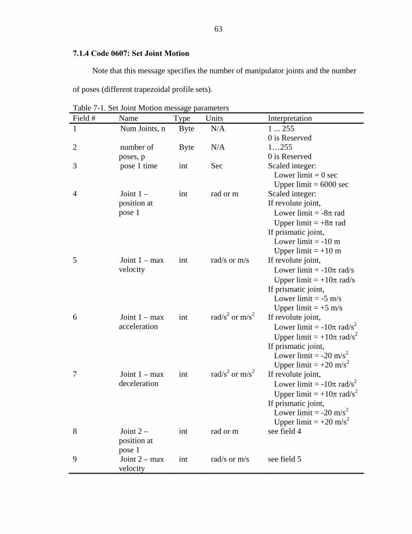
63
7.1.4 Code 0607: Set Joint Motion
Note that this message specifies the number of manip mber
o oses (di file sets
Table 7-1. S essage parameters Field # pe Units ion
ulator joints and the nu
f p fferent trapezoidal pro
et Joint Motion m
).
Name Ty Interpretat1 Byte N/A 1 ... 255
ed Num Joints, n
0 is Reserv2 of Byte N/A 1…255
3 Sec ec
it = 6000 sec 4 rad or m Scaled integer:
joint, Lower limit = -8π rad
it = +8π rad If prismatic joint,
er limit = -10 m it = +10 m
5 t /s or m joint, Lower limit = -10π rad/s
it = +10π rad/s If prismatic joint,
mit = -5 m/s Upper limit = +5 m/s
6 2 or joint, Lower limit = -10π rad/s2
it = +10π rad/s2
mit = -20 m/s2
Upper limit = +20 m/s2
7 2 or joint, Lower limit = -10π rad/s2
Upper limit = +10π rad/s2
/s2
2
number poses, p pose 1 time int
0 is Reserved Scaled integer: Lower limit = 0 s Upper lim
Joint 1 – int position at pose 1
If revolute
Upper lim
Low Upper lim
Joint 1 – max velocity
in rad /s If revolute
Upper lim
Lower li
Joint 1 – max acceleration
int rad/s m/s2 If revolute
Upper limIf prismatic joint, Lower li
Joint 1 – max deceleration
int rad/s m/s2 If revolute
If prismatic joint, Lower limit = -20 m Upper limit = +20 m/s
8 Joint 2 – position at pose 1
int rad or m see field 4
9 Joint 2 – max velocity
int rad/s or m/s see field 5

64
Table 7-1. Continued Field # Name Type Units Interpretation 10 Joint 2 – max int rad/s
acceleration 2 or m/s2 see field 6
11 deceleration
4n Joint n – int rad or m see field 4
velocity
acceleration
deceleration see field 7
-1) 4n+4 pose p time int s see field 3 -1) 4n+5 Joint 1 –
position at pose p
int rad or m see field 4
(p-1) 4n+6 Joint 1 – max velocity
int rad/s or m/s see field 5
(p-1) 4n+7 Joint 1 – max acceleration
int rad/s2 or m/s2 see field 6
(p-1) 4n+8 Joint 1 – max deceleration
int rad/s2 or m/s2 see field 7
… (p-1)8n Joint n –
position at pose p
int rad or m see field 4
(p-1)8n+1 Joint n – max velocity
int rad/s or m/s see field 5
(p-1)8n+2 Joint n – max acceleration
int rad/s2 or m/s2 see field 6
(p-1)8n+3 Joint n – max deceleration
int rad/s2 or m/s2 see field 7
Joint 2 – max int rad/s2 or m/s2 see field 7
…
position at pose 1
4n+1 Joint n – max int rad/s or m/s see field 5
4n+2 Joint n – max int rad/s2 or m/s2 see field 6
4n+3 Joint n – max int rad/s2 or m/s2
…(p(p

65
7.2 Manipulator End-Effector Discrete Pose Driver Component
7.2.1 Component Func
) is
hapter
s chapters, while Set End-Effector Path Motion
message is defined in Section 6.4.4. T the list of all the messages
assoc
coordinate system which is defined by a point and a quaternion at time t), the current
tion
The function of the Manipulator End-Effector Discrete Pose Driver (MEEDPD
to perform closed-loop control of the end-effector pose through a series of specified
positions and orientations.
7.2.2 Associated Messages
The MEEDPD (JAUS ID# 59) accepts the core input and output messages (C
1, Table 1-1). Some of the user defined messages that are received or sent by this
component were defined in previou
he following is
iated with this component:
• Set End-Effector Path Motion
• Report Manipulator Specifications
• Report Joint Effort
• Report Joint Positions
• Report Joint Velocities
• Set Joint Effort
7.2.3 Component Description
This component performs closed-loop control of the end-effector pose as measured
with respect to the vehicle coordinate system. The inputs are a path motion description
(discrete end-effector position and orientation at time t measured in the vehicle
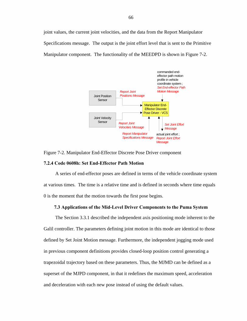
66
joint values, the current joint velocities, and the data from the Report Manipulator
Specifications message. The output is the joint effort level that is sent to the Primitive
Manipulator componen n in Figure 7-2.
t. The functionality of the MEEDPD is show
Manipulator End-Effector Discrete
Pose Driver - VCS
Joint PositionSensor
commanded end-effector path motionprofile in vehiclecoordinate system ;Set End-effector Path
Positions MessageMotion MessageReport Joint
Joint VelocitySensor
Set Joint EffortMessage
Report JointVelocities Message
Report ManipulatorSpecifications Message
actual joint effort ;Report Joint EffortMessage
7.2.4 Code 0608h: Set End-Effector Path Motion
A series of end-effector poses are defined in terms of the vehicle coordinate system
at various times. The time is a relative time and is defined in seconds where time equa
0 is the moment that the motion towards the first pose begins.
7.3 Applications of the Mid-Level Driver Components to the Puma System
The Section 3.3.1 described the independent axis positioning mode inherent t
Galil controller. The parameters defining joint motion in this mode are iden
Figure 7-2. Manipulator End-Effector Discrete Pose Driver component
ls
o the
tical to those
define sed d by Set Joint Motion message. Furthermore, the independent jogging mode u
in previous component definitions provides closed-loop position control generating a
trapezoidal trajectory based on these parameters. Thus, the MJMD can be defined as a
superset of the MJPD component, in that it redefines the maximum speed, acceleration
and deceleration with each new pose instead of using the default values.

67
Field # Name Type Units Interpretation Table 7-2. Set End-Effector Path Motion message parameters
1 number of poses, n Byte N/A 1 ... 255 0 is Reserved
2 time 1 int sec time for pose 1
Lower limit = 0 sec
Upper limit = +30 m
point for pose 1
for pose 1
quaternion q for pose 1 Lower limit = -1
8 b component of unit int N/A see field 6
9 c component of unit quaternio
int N/A see field 6
… 8n-6
int m see field 3
8n-2 d component of unit quaternion q for pose n
int N/A see field 6
8n-1 a component of unit quaternion q for pose n
int N/A see field 6
8n b component of unit quaternion q for pose n
int N/A see field 6
8n+1 c component of unit quaternion q for pose n
int N/A see field 6
Scaled integer:
Upper limit = 6000 sec 3 X component of tool
point for pose 1 int m Scaled integer:
Lower limit = -30 m
4 Y component of tool int m see field 3
5 Z component of tool point int m see field 3
6 d component of unit int N/A Scaled integer:
Upper limit = +1 7 a component of unit
quaternion q for pose 1 int N/A see field 6
quaternion q for pose 1
n q for pose 1
time n int sec see field 2 8n-5 X component of tool
point for pose n int m see field 3
8n-4 Y component of tool point for pose n
int m see field 3
8n-3 Z component of tool point for pose n
An identical approach is taken to determine the corresponding joint efforts
(Equation 6-1). Note however, that the proportional constant should change with the pk

68
magnitude of these parameters. Since this implementation is used to test rather then
optimize manipulator performance, previously determined values of are adequate for
operating speeds below 10000 encoder counts per second. T
completed a new set of parameters is applied to the system.
Unlike the MJMD, the functionality of the MEEDPD component is identical to that
of the MEEPD. It just allows for a single message to define multiple tool-point positions
and orientations to be executed autonomously at a particular time. N te that this
implementation uses generic timing functions provided with the Linux kernel. More
precise operation would require the use of a real-time operating system. All aspects of
software design are addressed in the following chapter.
pk
hus after each pose is
o

CHAPTER 8 OVERVIEW OF SOFTWARE DESIGN
anipulator
comp
associated with each of the components and
their
ts, this chapter begins its
analysis at the lowest level and moves up hierarchically. More specifically, it first
addresses the logistics behind the interface to the Galil controller, then goes into the
component and message development, and finally describes the node level functionality.
Due to a high level of redundancy, only one component out of the first three groups will
be analyzed in detail. Furthermore, this development takes advantage of multithreading, a
powerful tool described in many popular computer science books. From a software
development standpoint, each component is treated as a separate thread, and could be
The purpose of our study was to design and implement the JAUS m
onents. The design aspects were covered in Chapters 4, 5, 6, and 7, while the
software implementation is addressed here. Keep in mind that the chapter covers design
and logistics aspects rather than computer science technicalities. The source code is
rather complicated but well documented and could be easily read. For completion
purposes, this chapter gives a brief overview of the node manager and its role in
inter-component communications.
8.1 Overview
The scope of computer programming
corresponding messages reflects the importance of software design in this and any
other large scale project. In order to allow for easy and clear understanding behind the
process control and data flow in each of the functional elemen
69

70
compared to a program running a while-loop. An additional thread is used in the interface
to the controller.
8.2 The Interface to the Galil Controller
The Section 3.4 gave an overview of the C function prototypes that are the core of
this development. Only a single program/thread is responsible for communications with
the Galil controller eliminating the need for multithread synchronization. The file
galilInterface.c is responsible for managing startup and shutdown routines of this
particular thread. The interface has a well defined structure that is shown in Figure 8-1:
Figure 8-1. The galilInterface.c logic flow diagram

71
On startup, the code checks whether the RoboWorks 3-D software tool is used.
This p
next chapter. RoboTalk is the program that
handles Ethernet communications between the computer hosting RoboWorks and the
computer providing position data. The file RoboTalk.h contains function prototypes for
queried using “TP”, “TV”, and “TT” commands, respectively. Regardless of the fact that
the Puma 762 does not have any torque sens plemented for
testin the
g the
e
ackage, developed at the University of Texas, was slightly modified to work with
the Linux operating system for both simulation and real-time 3D display purposes. Its
application will become more apparent in the
the Connect(), SetTagValues(..), and Disconnect() functions shown in Figure 8-1. This is
followed by establishing a connection to the Galil controller, resetting it for safety
purposes, and calibrating all the joints using stored potentiometer values.
After the state thread is started, position, velocity and force/torque values are
ors, this component was im
g purposes. Commanding an independent jogging motion is accomplished using
“JG” command (e.g. if the Primitive Manipulator commands a 50% effort, this is
converted to -2500 encoder counts per second velocity using Equation 6-2, assumin
maximum velocity is 5000 encoder counts per second). In addition to the core
functionality, galilInterface.c is used to set up maximum speed, acceleration, and
deceleration values using “SP”, “AC”, and “DC” commands generating a trapezoidal
profile. The function is set as a sleeper outside the thread and will change the values only
if called. Only the Manipulator Joint Motion component is responsible for changes to th
default parameters. The file also contains a homing function that could take the
manipulator to its home position on startup. This capability should be used after
recalibration of joint values. The source code for galilInterface.c, RoboTalk.c, and

72
corresponding header files is listed in Appendix B, Section B.1. The Primitive
Mani e
are
is very similar. Figure 8-2 shows the functional elements of a
generic component file.
pulator component and all of the sensor components acquire data from the interfac
file using external access functions eliminating the need for the use of global variables.
8.3 Component Level Software Development
Components are based on standardized interfaces (Section 1.3.4). From a softw
development standpoint, this means that the code structure of the files defining these
unique JAUS entities
Figure 8-2. Generic component logic flow diagram

73
Each component follows a standard process flow defining thread startup and
shutdown routines. As it is shown in Figure 8-2, each component consists of two threads.
The first is responsible for performing com hile the other handles the
incoming core and user-define the state thread that the
partic mergency,
w
ponent function w
d messages. Therefore it is in
ular component’s behavior is defined. This implementation defines E
Failure, and Shutdown states identically across the entire node. In order to better
understand the inner workings of these JAUS elements, the state thread of one component
from each of the Chapters 4, 5, and 6 is analyzed.
8.3.1 Primitive Manipulator State Thread
The best way to represent the processes within a particular file is using a flo
chart. Therefore, Figure 8-3 shows the PM state thread.
Figure 8-3. The Primitive Manipulator state thread logic flow diagram

74
Each component is set to the Initialize state by default during the startup routine.
While at this state, the PM accesses the information provided by the interface to the Galil
controller requesting the status on initialization procedures, ensuring all integrity checks
are complete and the system is up and running. Once the component enters the Ready
state, it talks to the interface file again, but this time accessing the function directly
responsible for commanding motion, given the joint effort values. The source code for
the file pm.c and its corresponding header is documented in Appendix B.2.
8.3.2 Manipulator Sensor Components
The state thread of Manipulator Joint Position Sensor is described in this section as
it provides more complex functionality than the other sensor components. Definitions of
Initialize, Standby and Ready states are shown in Figure 8-4.
Figure 8-4. Manipulator Joint Position Sensor logic flow diagram

75
The definition of the initialize state in the above diagram is applied to the
remainder of the components on this node. If the query status message to the Primitive
Manipulator returns Ready, it is assumed that the initialization procedure was successful.
Once in the Ready state, the MJPS accesses the Galil interface file and queries it for
position. Next, it checks those values ensuring that none of the joints are crossing
position limits, or getting close to a singularity configuration. In either case, the MJPS
changes the status of the Primitive Manipulator to the Emergency state. This instantly
causes all the other components to go into the Emergency state as well. The system
would now have to be reinitialized. The source code for the mjps.c file and the
corresponding header is listed in the Appendix B.3.
8.3.3 Low-Level Position and Velocity Drivers
It should be noted, that all states, except Ready, are defined in the same manner as
covered in previous sections across all of the remaining components. Figure 8-5 shows
the MEEPD state thread (Ready state only).
Figure 8-5. Manipulator End-Effector Pose Driver logic flow diagram

76
The Figure 8-5 simply states that this component performs its unique function as
long as th itive Manipulato
the software functionality is defined, and since the timing functional -level
components is a trivial addition, it is not discussed in detail. However, f tion
purposes, Appendix B.4 and Appendix B.5 list the meepd.c and the meedpd.c files and
eir corresponding headers, respectively.
8.4 Message Level Softw
Each manipulator component sends or receives user defined messages. Prior to
algorithms are well defined and easy to implement. They are based on converting a
preserving correct values. These functions can further clip passing parameters if they lay
its. Information being passed is defined as a structure type so that
it. For example, joint velocities are
sent b
uma system, it also ensures that both the Val
and Galil controllers, as well as the arm itself are powered up before starting the interface
thread. The order in which the components are started up is irrelevant, but should be
ere is no change in th f the Prime status o r. At this point all of
ity of the mid
or comple
th
are Development
messages being exchanged, they are compressed (packed) and eventually uncompressed
(unpacked) once they reach the destination (Section 1.3.5). Packing and unpacking
desired parameter into a byte stream, thus using a correct byte counter is critical for
outside the specified lim
it is easily accessed by the components requesting
y the MJVD component as a part of a jointVelocity_t structure containing six
velocity values and a parameter defining the total number of joints. Message files and
their corresponding headers are documented in the Appendix C.
8.5 Node Level Software Development
The Manipulator Control node is responsible for startup and shutdown of all the
manipulator components. In the case of the P

77
consistent with the order in which they are shutdown. Two files, mc.c and mc.h, are listed
in the Appendix B.6.
nager ator
o JA omp sible fo nent co re
the C munic and th nger. Th r allows nt of
message entry into a sub aint nk betw ms.
he N
nsible for starting the node itself.
ronment for display purposes.
How in the
is listed in the Appendix B.7.
8.6 Node Ma and Communic
Tw US c onents respon r all inter-compo mmunications a
om ator e Node Ma e Communicato for a single poi
system while m aining the data li een the subsyste
T ode Manger component is responsible for routing JAUS messages from one node
to another. When a component sends a message [7], it first goes to the Node Manager
where the information regarding the destination component is interpreted and passed onto
the communicator, which handles the transmission of the message to the proper nod.
Finally, at the highest level, the main file is respo
This file further uses a “curses” text-based window envi
the information is being displayed for each of the components is discussed
next chapter. The main.c file

CHAPTER 9 TESTING AND RESULTS
This chapter covers the methods used to test 2 aspects of this JAUS
implementation. The first ensures that the functionality of developed messages and
components meets the JAUS specification requirements. The latter looks at how well this
architecture handles manipulator control from the view point of accuracy and task
completion. In order to adequately test this implementation, an additional component
mimicking a Subsystem Commander (SSC) was created. The manipulator sensor
components are self tested as the information they provide becomes critical to
entially 7
different cases or scenarios pertaining to the functionality of the driver components are
evaluated by the SSC. User input is required when choosing the scenario, however the
current setup mandates that any parameter change has to be done in the source code.
9.1 Subsystem Commander Component Overview
The Subsystem Commander component is defined in the JAUS Reference
Architecture document. Its function is to coordinate all activity within a given subsystem.
The SSC (JAUS ID# 32) has the responsibility of performing mission planning, issuing
commands, and querying status for the subsystem operation. The document states that
functions of this component may be performed by humans, or by the computer or both
[7]. The capabilities of the RoboWorks software package are integrated with this
component to display real-time position data of the manipulator. This could be useful
when the commander is located off site. Figure 9-1 shows this operator control setup.
components responsible for closed-loop position and velocity control. Ess
78

79
Figure 9-1. Subsystem Comm operator graphical user interface
9.2 Case 1: Set Joint Effort
t without any
nsor feedback. In order to ensure that no other components are commanding joint
efforts, their status is changed to the Standby state. Note that the case numbers
correspond to the items listed in Figure 9-1. Set Joint Effort Message commands the
following set of values:
ander
The first scenario is used to test the Primitive Manipulator componen
se
[ ]121212151515 −−−=effort (9-1)
Given the default maximum velocity value of 5000 encoder counts per second
(enc/s) for the first three joints and 1000 enc/s for the last three joints, these values are
converted back to [750, -750, 750, -120, 120, -120] enc/s as they are passed on to the

80
Galil controller using Equation 6-2. Figure 9-2 shows a snapshot of the Primitive
Manipulator screen during the execution of this command.
Figure 9-2. Primitive Manipulator Screen as it responds to the Set Joint Effort message
Note that the current effort values are slightly different from the commanded ones.
This error ranging between 1% and 4% is inherent to the underlying theory behind the
independent jogging mode covered in Chapter 3. Figure 9-2 also shows that the PM
screen is used to display the contents of the Manipulator Specifications message.
Mechanism and controller information is also available. It is useful to realize that in this
and the upcoming sections, any information regarding position and velocity information
is displayed in units of encoder counts (enc) and encoder counts per second (enc/s),
respectively. This was done for practical purposes to allow for quick interpretation of the
corresponding positions with the actual ones. Table 1-1 lists the conversion factors used
to go from specified JAUS standard units to enc and enc/s and vice versa:

81
Table 9-1. The Puma 762 platform specific conversion factors Joint # Rad der Co der Cians to Enco unts Enco ounts to Degrees
1 45836.6 0.00125 2 51.9 0.00086875 57.5 0.001115625 52.6 152.6 285.3
6593 5134 91 0.00626 5 9 0.00626 6 4 0.01337
9.3 Case 2: Set Joint Position
This case tests the capabilities of the Manipulator Joint Position Driver. The SSC
simply commands six joint values corresponding to the desired joint positions. That
information is then used to determine the corresponding joint efforts (Equation 6-1) that
are passed to the PM. Unlike the PM, MJVD, and MEEVD components, this and the
other position drivers use the independent jogging mode to command position. This
requires an introduction of an additional loop to the existing control system as shown in
Figure 9-3.
Figure 9-3. External closed-loop control diagram
are tuned to provide
stable ge of
f K values and
potentially a more complicated control loop. The values of K and motion parameters used
in this project are summarized in Table 9-2.
The value of K is determined experimentally and its values
, no-steady-state-error operation of each of the joints within a particular ran
motion parameters. The Puma 762 system is capable of high-speed operation with great
accuracy; however such implementation would require a different set o

82
Table 9-2. Values of the K constant and corresponding range of motion parameters
Joint # K Max Speed
(end/s) Max Acceleration
(enc/s2) Max Deceleration
(enc/s2)
1 34 1000-10000 28000-256000 28000-256000 2 34 1000-10000 28000-256000 28000-256000 3 34 1000-10000 28000-256000 28000-256000 4 34 250-1000 28000-256000 28000-256000 5 15 250-1000 28000-256000 28000-256000 6 14 250-1000 28000-256000 28000-256000
To further illustrate the performance of the manipulator system within these ranges,
the MJPS is commanded the sam
ters. Keep in mind that when this or any other
Manipulator and the senso
9.3.1
lues of the K constant and “average” set of motion parameters
JoMax Speed Max Acceleration Max Deceleration
e position, [35000, -35000, 50000, 5500, 6500, -4000],
with three different sets of motion parame
driver component enters the Ready state, all other components except the Primitive
rs are set to Standby.
The “Average” Set
Table 9-3 shows the set of “average” motion parameters used to test the
performance of the MJPD.
Table 9-3. Va
int # K (end/s) (enc/s2) (enc/s2)
1 34 5000 128000 128000 2 34 5000 128000 128000
128000 4 34 1000 5 15 1000 128000 128000
3 34 5000 128000 128000 128000
6 14 1000 128000 128000
are shown The step responses of each of the joints as they are commanded motion
in Figure 9-4.

83
Joint 1
0.5
0.70.8
on (r
a
0
0.10.
0.
2
30.4
0.6
0.9
0 5 10 15Time (s)
Pos
itid)
Joint 2
-0.3
-0.2
-0.10 5 10 15
n (r
ad
-0.4Posi
t
-0.6
-0.5
0
Time (s)
io)
Joint 3
0
0.2
0.4
0.8
1
1.2
Pos
iti (r
ad)
0.6
0 5 10 15Time (s)
on
Joint 4
0
0.1
0.2
0.3
0.4
0.5
0.6
0.7
(rad
)
0 5 10 15Time (s)
Pos
ition
Joint 5
0
0.1
0.2
0.3
0.4
0.5
0.6
0.7
0.8
0 5 10 15Time (s)
Posi
tion
(rad)
Joint 6
-1-0.9
-0.8-0.7-0.6-0.5
-0.4-0.3-0.2
-0.10
0 5 10 15
Time (s)
Posi
tion
(rad
)
Figure 9-4. Joint step responses using “average” motion parameters
Figure 9-5. The MJPD screen as motion is completed under the “average” set
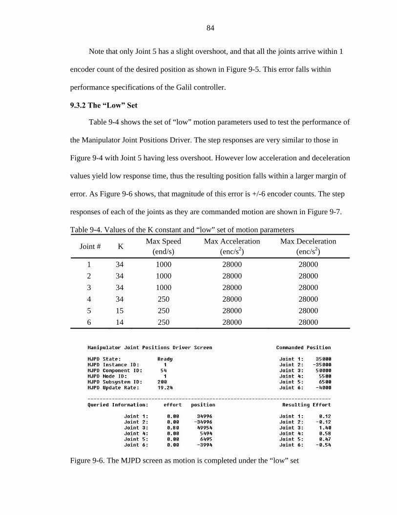
84
Note that only Joint 5 has a slight overshoot, and that all the joints arrive within 1
encoder count of the desired position as shown in Figure 9-5. This error falls within
performance specifications o
9.3.2
ance of
ration
re 9-7.
Joint # K Max Speed Max Acceleration
2Max Deceleration
2)
f the Galil controller.
The “Low” Set
Table 9-4 shows the set of “low” motion parameters used to test the perform
the Manipulator Joint Positions Driver. The step responses are very similar to those in
Figure 9-4 with Joint 5 having less overshoot. However low acceleration and decele
values yield low response time, thus the resulting position falls within a larger margin of
error. As Figure 9-6 shows, that magnitude of this error is +/-6 encoder counts. The step
responses of each of the joints as they are commanded motion are shown in Figu
Table 9-4. Values of the K constant and “low” set of motion parameters
(end/s) (enc/s ) (enc/s
1 34 1000 28000 28000 2 34 1000 28000 28000 3 34 1000 28000 28000
5 15 250 28000 28000 6
4 34 250 28000 28000
14 250 28000 28000
Figure 9-6. The MJPD screen as motion is completed under the “low” set

85
Joint 1
0
0.10.2
0.3
0.4
0.6
0.7
0.9
sitio
nd)
0.5
0.8Po
(ra
0 20 40 60 80Time (s)
Joint 2
-0.3
-0.2
-0.1
00 20 40 60 80
ition
(ra
-0.5
-0.4Pos
d)
-0.6Time (s)
Joint 3
0
0.4
0.6
0.8
1
Time (s)
Pos
on (r
ad)
0.2
1.2
0 20 40 60
iti
80
Joint 4
0
0.2
0.4
0.6
Time (s)
Pos
on (r
ad)
0.1
0.3
0.5
0.7
0 20 40 60 80
iti
Joint 5
0
0.
0.
0 20 40 60 80Time (s)
Posi
tion
(
0.7
0.8
0.5
0.6
rad)
0.1
0.2
3
4
Joint 6
-1
-0.9
-0.8
-0.7
-0.4
-0.3
-0.2
-0.1
00 20 40 60 80
Time (s)
Poad
)
-0.6
-0.5
sitio
n (r
Figure 9-7. Joint step responses using “low” motion parameters
9.3.3 The “High” Set
Table 9-5 shows the set of “high” motion parameters used to test the performance
of the MJPD. The step responses of each of the joints as they are commanded motion are
shown in Figure 9-8. High values of maximum speed, acceleration and deceleration
govern the quick response to the commanded position.

86
Table 9-5. Values of the K constant and “high” set of motion parameters
Joint # K Max Speed
(end/s) Max Acceleration
(enc/s2) Max Deceleration
(enc/s2)
1 34 10000 256000 256000 2 34 10000 256000 256000 3 34 10000 256000 256000 4 34 2500 256000 256000 5 15 2500 256000 256000 6 14 2500 256000 256000
Joint 1
0.1
0.2
0.3
0.4
0.5
0.6
0.7
0.8
0.9
Posi
tion
(rad
)
00 2 4 6 8
Time (s)
Joint 2
-0.6
-0.5
-0.4
-0.3
-0.2
-0.1
00 2 4 6
Time (s)
Posi
tion
(rad
)
8
Joint 3
1
1.2
0
0.2
0.4
0.6
0.8
0 2 4 6 8Time (s)
Posi
tion
(rad
)
Joint 4
0
0.1
0.2
0.3
0.4
0.5
0.6
0.7
0 2 4 6 8Time (s)
Posi
tion
(rad
)
Joint 5
0
0.1
0.2
0.3
0.4
0.5
0.6
0.7
0.8
0.9
0 2 4 6 8Time (s)
Posi
tion
(rad
)
Joint 6
-1
-0.9
-0.8
-0.7
-0.6
-0.5
-0.4
-0.3
-0.2
-0.1
00 2 4 6
Time (s)
Posi
tion
(rad
)
8
Figure 9-8. Joint step responses using “high” motion parameters

87
Unlike the other two cases, this “high” case starts to show some signs of
instability in the initial part of the motion, but quickly recovers with resulting position
error within the Galil controller specifications as shown in Figure 9-9.
Figure 9-9. The MJPD screen as motion is completed under the “high” set
Figure 9-10 shows the final configuration of the PUMA 762 manipulator as seen by
the Subsystem Commander component.
Figure 9-10. Subsystem Commander screen showing the final configuration of Puma 762
88
9.4 Case 3: Set End-Effector Pose
This section shows the performance of the Manipulator End-Effector Pose Driver
Component. As described in Chapter 8, this component is responsible for computation of
independent joint efforts based on the commanded position and orientation of the
end-effector.
In order to adequately perform the forward or reverse position analysis, the joint
angles that correspond to the manufacturer’s specifications need to be converted to the
kinematic values or vice versa using the following relationship:
2,1, KK ermanufacturikinematici += θθ (9-2)
where values of correspond to the conversion factors shown in column 3 of
Table 9-1, and values of are [0, 90, 90, 180, 180, 0] for Joints 1, 2, 3, 4, 5, and 6
respectively. The orientation of the end-effector is expressed using a unit quaternion.
Simp used to convert the four values defining a
quaternion into the and vectors. Once the analysis is complete, the function
returns up to eight possible solution sets. An optimization technique is used to pick one
solution by defining a total cost function given in Equation 9-3:
1K
2K
le approach outlined in Section 2.3.5 is
67aF6SF
⎟⎠
⎜⎝
−iK ,1
80⎟⎞
⎜⎛ −
= curridesi ppCost ,, )(
min (9-3)
d
manufacturer’s values required in the calculation of the desired joint efforts. Hence, the
results of the commanded position [908, -602, 512] mm and orientation [0.4650,-0.1810,
-0.8030,-0.3320] are shown in Figure 9-11.
Thus, the solution requiring the least amount of encoder counts to get to the desire
position and orientation is chosen. Those angles are then converted back to the

89
Figure 9-11. The MEEPD screen as it responds to Set End-Effector Pose message
The computation of errors associated with the resulting position and orientation is
non-trivial and is not covered in this thesis. However, it should be noted that the resulting
joint angle positions are within 2 encoder counts with respect to those computed using the
reverse position analysis.
9.5 Case 4: Set Joint Velocities
This scenario is very similar to that covered in Section 9.2 since joint efforts are
interpreted as joint velocities. The only difference is that joint velocities are now
converted back to joint efforts and then back to velocities at the interface level. Figure
9-12 shows the Manipulator Joint Velocities Driver screen during the commanded
motion. The individual joint velocities are calculated using Equation 6-1 with “average”
parameter set defining maximum joint velocity. Therefore, a Set Joint Velocities message
commanding [-3000, 2500, -3500, 500, -300, 250] for joints 1, 2, 3, 4, 5, and 6
respectively yields [-60, 50, -70, 50, -30, 25] joint efforts as shown in Figure 9-12.

90
Figure 9-12. The MJVD Screen as it responds to Set Joint Velocities message
It is apparent that very close values of velocity are obtained with the larges
0.5% occurring in motion of joint 1. This e
t error of
rror is inherent to the theory behind the
independent jogging m
contro
included in this document due to the time constraints.
otion, since the “JG” command is directly passed to the Galil
ller.
9.6 Case 5: Set End-Effector Velocity State
This section is supposed to evaluate the performance of the Manipulator
End-Effector Velocity State Driver. This component takes as input the desired velocity
state of the end-effector and computes the resulting joint velocities. Any commanded
motion will reach a singularity configuration if not terminated in time; hence the motion
has to be constantly monitored and carefully selected. In addition, since the resulting
velocities vary as the end-effector moves in a commanded direction, the “high” set of
maximum parameters is used in for this application allowing for a wide range of possible
solutions. Once determined, the joint velocities are converted into efforts and passed to
the PM. The collection of results for this section is still in progress and might not be

91
9.7 Case 6: Set Joint Motion
This case is in many ways similar to Case 2, in that it uses the same approach to
compute the resulting joint efforts. However, the major difference is seen as this
component sets the parameters defining the trapezoidal trajectory profile with each pose.
As a result, neither of the “average”, “low” or “high” sets are used in this
implementation, but rather a custom set is created with each pose. In this example, the
SSC sends a message to the Manipulator Joint Move Driver containing three different
poses. The results as well as the resulting trajectory profiles are covered in the following
sections.
9.7.1 Set Joint Motion: Pose 1
The snapshot of the MJMD screen after the completion of the first pose is shown in
Figure 9-13.
Figure 9-13. The MJMD screen showing component status upon completion of pose 1

92
The desired trapezoidal motion parameters are listed above. Figure 9-14 shows the
velocity performance plot displaying the actual motion parameters for each of the joints.
Joint 2Joint 1
-0.1
-0.06
-0.04
0 5 10 15 20 25
Time (s)
-0.08
-0.02
0
0.02
0.04
0.06
0.08
0.1
0.12
Velo
city
(rad
/s)
0.1
0.08
0.04
0.06
/s)
-0.06
-0.04
-0.02
0
0.02
0 5 10 15 20 25
Time (s)
loci
ty (r
Vead
Joint 3
-0.08
-0.06
-0.02
0
0.02
0.04
0.08
0.12
0 5 10 15 20 25Velo
y (r
ad/s
-0.04
0.06
0.1
Time (s)
cit
)
Joint 4
-0.02
0
0.02
0.04
0.08
0.12
0 5 10 15 20Velo
y (r
ad/s
-0.08
-0.06
-0.04
0.06
0.1
25
Time (s)
cit
)
Joint 5
-0.08
-0.06
-0.04
0
0.02
0.04
0.06
0.1
0 5 10 15 20 25
Time (s)
Velo
city
d/s)
-0.02
0.08
0.12
(ra
Joint 6
-0.15
-0.1
-0.05
0
0.05
0.1
0.2
Time (s)
Velo
city
d/s)
0.15
0.25
0 5 10 15 20 25
(ra
Figure 9-14. Joint performance plots for motion parameters set in pose 1
It is apparent that these plots closely follow the desired parameters with the
exception to the deceleration stage which is affected by the additional control loop that
was introduced in Section 9-3. In this stage, the component constantly reduces
commanded velocity values that are then passed to the Galil controller which then once

93
again
all values
al
o
ithin +/-1 encoder counts.
9.7.2
uses a trajectory generator to close the loop. The incremental position parameter
used in the Galil “JG” function is not specified, thus the controller uses very sm
to set the path by default. The combination of the two control loops provides addition
damping. Similar behavior can be observed in the upcoming sections. Referring back t
Figure 9-13, it can be seen that the resulting positions are w
Set Joint Motion: Pose 2
The snapshot of the MJMD screen after the completion of the second pose is shown
in Figure 9-15.
Figure 9-15. The MJMD screen showing component status upon completion of pose 2
performance plot showing the actual motion parameters for each of the joints.
The second set of joint positions goes in effect after 30 seconds of the component
startup. The Puma was commanded to go back to its home position, which was
successfully accomplished in a little over 23 seconds. The desired trapezoidal motion
parameters for pose 2 are listed in Figure 9-15. Figure 9-16 depicts the velocity
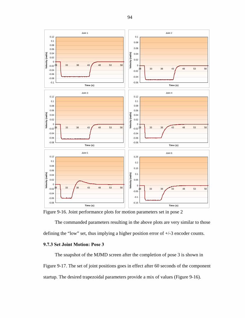
94
Joint 1
-0.08
-0.06
-0.02
0
0.02
0.04
0.08
0.1
28 33 38 43 48 53 58
Time (s)
Velo
cit
ad/s
)
-0.1
-0.04
0.06
0.12
y (r
Joint 2
-0.04
0
0.04
0.08
28 33 38 43 48 53 58
Time (s)
Velo
city
ad/s
)
-0.06
-0.02
0.02
0.06
0.1
(r
Joint 3
-0.08
-0.06
0.04
58elo
/s
-0.04
-0.02
0
0.02
0.06
0.08
0.1
0.12
28 33 38 43 48 53Vci
ty (r
ad)
Time (s)
Joint 4
-0.06
-0.04
-0.02
0.04
28 33 38 43 48 53 58Velo
/s
0
0.02
0.06
0.08
0.1
0.12
city
(rad
)
-0.08Time (s)
Joint 5
-0.06
-0.02
0
0.02
0.04
0.08
0.1
0.12
28 33 38 43 48 53 58Velo
(rad
/s)
-0.08
-0.04
0.06
Time (s)
city
Joint 6
0
0.05
0.1
0.15
0.2
0.25
28 33 38 43 48 53 58Velo
c (r
ad/s
)
-0.15
-0.1
-0.05
Time (s)
ity
Figure 9-16. Joint performance plo ters set in pose 2
se
nt
he desired trapezoidal parameters provide a mix of values (Figure 9-16).
ts for motion parame
The commanded parameters resulting in the above plots are very similar to tho
defining the “low” set, thus implying a higher position error of +/-3 encoder counts.
9.7.3 Set Joint Motion: Pose 3
The snapshot of the MJMD screen after the completion of pose 3 is shown in
Figure 9-17. The set of joint positions goes in effect after 60 seconds of the compone
startup. T

95
onent status upon completion of pose 3 Figure 9-17. The MJMD screen showing comp
Joint 1
-0.04
-0.03
-0.02
-0.01
0
0.01
0.02
58 78 98 118 138
Time (s)
Ve/s
)lo
city
(rad
Joint 2
-0.04
-0.03
-0.02
-0.01
0
0.01
0.02
58 78 98 118 138
Time (s)
Velo
city
(rad
/s)
Joint 3
-0.02
-0.01
0
0.01
0.02
0.03
0.04
58 78 98 118 138
Time (s)
Velo
city
(rad
/s)
Joint 4
-0.04
-0.03
-0.02
-0.01
0
0.01
0.02
0.03
0.04
58 78 98 118 138
Time (s)
Velo
city
(rad
/s)
Figure 9-18a. Joint performance plots for motion parameters set in pose 3

96
Joint 6
-0.08
-0.07
-0.06
-0.05
-0.04
-0.03
-0.02
-0.01
0
0.01
0.02
58 78 98 1
Joint 5
-0.02
-0.01
0
0.01
0.02
0.03
0.04
58 78 98 118 138
Time (s)
Velo
city
(rad
/s)
18 138
Ti e (s)
Velo
city
(rad
/s)
m Figure 9-18b. Joint performance plots for mo on parameters set in pose 3
Comm
reached in approximately 80 seconds with the der cou ts. Figures
9-18a and 9-18b show the velocity performance plot showing the actual motion
parameters for each of the joints.
iscrete Pose
river. This component can be considered a superset of the MEEPD in that it
ndamentally performs the same function with the ability of the user to specify the
end-effector path or profile. In other words, this component takes as input the message
that specifies multiple positions and orientations of the end-effector at different times. A
test sample message contains five different end-effector pose sets, the two of which are
shown in Figure 9-19 and Figure 9-20. The “average” set of motion parameters is used
for this component by default and thus the accuracy of +/- 3 encoder counts was obtained
with all the results. This chapter has successfully shown that all the information
communicated between the JAUS components is done correctly. It has also illustrated
that each component properly performs its required tasks, outlined in Chapters 4-7.
ti
anded joint positions [-62000, -65000, 65000, 5000, 5000, -5000] are
accuracy of +/-5 enco n
9.8 Case 7: Set End-Effector Path Motion
This section tests the capabilities of the Manipulator End-Effector D
D
fu
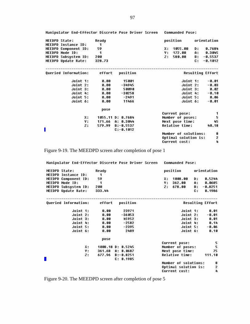
97
Figure 9-19. The MEEDPD screen after completion of pose 1
Figure 9-20. The MEEDPD screen after completion of pose 5

98
Finally, the chapter defined a range of joint motion parameters which will ensure
ulator system. The last
formation covered in this thesis and offers some ideas
evelopment and alternative platform implementations.
stable, minimal steady-state-error operation of the Pum 762 manip
chapter summarizes all the in
regarding future component d

CHAPTER 10 CONCLUSIONS AND FUTURE WORK
10.1 Conclusions
d on the design and development of 9 components used to
m. Considering that these components are
lo for the Joint Architecture for Unmanned Systems (JAUS), this development
, each of the components had to meet the
ed JAUS component. Second, a testing platform had to be chosen,
anipulator components had to be applied to the test
ormance of this platform had to be tested under the
ew architecture.
A standard JAUS component is defined through a set of 4 criteria: the function of
utput messages that the component may handle,
these terms, all 9 components were fully
stra he function was clearly defined for each of the
ponents, varying from the simple open-loop control, to the discrete closed-loop
and discuessed the specifics of their individual
Our study focuse
command and control a manipulator ar
deve ped
had to meet three specific objectives. First
criteria of a fully defin
and the functionality of the m
platform. Finally, the perf
implementation of the n
the component, the accepted input and o
and the full description of the component. In
con ined to the JAUS architecture. T
com
end-effector position control. A full set of input and output messages were defined to
meet the JAUS message standards. The component description defined the
implementation of these components into the JAUS architecture, set the corresponding
and unique identification numbers,
functionality.
99

100
T as chosen as the testing platform due to the availability and
prior to this
otion
ontroller was kept to
accomplished.
r component was used to interpret
sed
e
ace.
our study involved the programming
lements on 4 levels. The design aspect took advantage of the
m
vel
the
rtup and shutdown routines of the Manipulator Control node. This
for displaying all of the information pertaining to the
tandard to many
d in terms of the
the J
of the components. The results were
cations of the Puma robot under the new
he Puma 762 robot w
acceptable operating condition. The robot was reverse engineered
implementation to accommodate a commercially available Galil DMC-2100 m
controller. Some of the safety functionality of the native Val II c
ensure that proper initialization routines are
The implementation of the Primitive Manipulato
joint efforts as joint velocities with respect to the commands that the Galil controller u
to perpetuate motion. This approach uses an independent jogging mode inherent to th
Galil controller interf
The scope of the software development during
of the JAUS functional e
multithreading tool and applied it to each of the components allowing a single progra
on a node level to spawn and run all of the manipulator components. On the lowest le
a program had to be created to be able to interface the C based JAUS software to
Galil machine-based command language. On the highest level, the main program was
used to handle the sta
program was further responsible
particular component using the curses windows development tool s
Linux distributions.
F ally, e perfin th ormance of each of the components was teste
guidelines set by AUS for component functionality. This was accomplished by
passing the specific commanding messages to each
used to determine the performance specifi

101
modular architecture. More specifically, the accuracy of the resulting position and
l, are
a small
rgin of error inherent to the independent jogging mode as it uses the trajectory
oop position control. Second, messages sent through the node
he process of packing and unpacking. Finally, a
ons with
s
ponents
s tested successfully on the Puma 762 Robot. It can be assumed that these components
ons.
autonomous control of an
arm that would be a part of the vehicle-manipulator
he aspects of low-level and
id-lev ed
both teleop and
mplementation was only able to address one of the two
v i c and 15 enc/s, respectively. Such errors, even though smalelocity is with n 6 en
still significant especially if high precision operation is required by the particular
application. There are 3 reasons that could explain the inaccuracies. First, there is
ma
generator for closed-l
manager lose some precision during t
small frequency associated with the interface thread responsible for communicati
the Galil controller provided delayed information to the commanding component
running at much higher update rates.
O erall, e Manv th ipulator Control node containing 9 JAUS manipulator com
wa
could be now implemented on any serial manipulator system with slight modificati
Moreover, infrastructure in place allows for both teleop and
independent m, as wellar as an
system.
10.2 Future Work
This implementation has successfully addressed t
m el controls of manipulators. More specific messages oriented towards advanc
task completion could be added to the current node. The next major step would be to test
th l a a vehicle-manipulator system requis imp ement tion on iring
autonomous control, as this i
aspects.

APPENDIX A EQUATIONS FOR A SPHERICAL HEPTAGON
71 s
543 ss=
Table A-1. Fundamental formulas for a Spherical Heptagon 66712345 ssX = csY 67cZ = 66712345 = 12345
Z771ssX = 77123456 csY = 7123456 c=
=
1234567 cZ = 23456
112345 ssX = 3456Y67
223
1127 cs=
456X = s 22345671 csY = 2345671 cZ =
334ssX =
44567123 ssX = 56712 33456712 csY =
44567123 csY = 3456712 cZ =
4567123 cZ =
55671234 ssX = 55671234 csY = Z 5671234 c
767ssX = 76754321 csY = 6754321 cZ =
7165432 cZ =
1276543 cZ =
54321
17132 ss 654X = 17165432 csY =
21276543 csY = 76X 212
32317654 ssX = 32317654 csY = 2317654 cZ =
43421765 ssX 43421765 csY 3421765 cZ = = =
54532176 ssX 54532176 csY 4532176 sZ = = =
656ssX = 65643217 csY = 5643217 cX = 43217
102

103
Table A-2. Subsidiary formulas for a Spherical Heptagon Set 1
612345 X X =
723456 XX =
134567 X X =
245671 XX =
356X =712 X
467123 XX =
571234 XX =
754321 XX =
1XX = 65432
276543 XX =
3 176 XX =54
4XX =21765
5XX =32176
6X 43217X =
612345* YX =− 612345 ZZ =
723456 YX =− *123456 ZZ =
134567* YX =− 234567 ZZ =
245671* YX =− 345671 ZZ =
456712 ZZ =
567123 ZZ =
671234
356712* YX =−
467123* YX =−
571234 YX * =− ZZ = 754321
* Y= X− 754321 ZZ =
165432* YX =−
276543* YX =−
3
165432 ZZ =
276543 ZZ =
317654 ZZ = 17654*X− Y=
6 Y=
421765 ZZ = 421765 YX =− *
*
532176 ZZ =
643217 ZX = 3217X− 5
643217* YX =−
O tion
sines or the
ther sets re d to this configuration as well as the derivations of the direclate
co f spatial heptagon are listed in the Appendix section of [9].

APPENDIX B IPULATOR COMPONENTS: SOURCE CODE JAUS MAN
B.1 The GalilInterface.c File and the Corresponding Header GalilInterface.h
//// //////////////////////////////////////////////////////////// terface.c
0.1 Original Creation gnjen Sosa ([email protected]) om Galluzzo ([email protected])
09/28/2004
This file contains the C code used to interface JAUS to PUMA 762 manipulator and the GALIL DMC2100 controller.
////////////
nclud
cludInterface to the Galil Controller Interface to the RoboWorks software efines getRoboWorksReady() function
rc = 0; // Return code // Response from the controller ] = "";// Command to the controller
// Handle to controller fInMotion[NUM_JOINTS]; // Motion complete flag
ntrollerinfo; // Controller information structure [] ={0x12,0x16,'\r',0x0};
he computer on ning
, "Puma_J2", "Puma_J3", "Puma_J4", "Puma_J5", "Puma_J6"};
rfaceRun;
];
/ ////////////////////// galilIn
//// File:
sion: // Ver// Written by: O
T// Template by: : // Date
// Description://
/ ////////////////////////////////////////////////////////////////////////////// #include <ctype.h> #include <stdlib.h>
nclude <stdio.h> #i#include <string.h>
e <math.h> #i#include <errno.h> #include <sys/time.h> #include <unistd.h> #include <pthread.h> #include "galilInterface.h" #include "mcConstants.h" // Constants used across Manipulator Control Node #include "logLib.h" // Debug functions
e "timeLib.h" // Timing functions #in#include "dmclnx.h" // include "RoboTalk.h" // #
#include "mc.h" // D
s // Controller Variablelong char buffer[32] = "";har g[128c input_strin
MC hdmc = -1; HANDLEDint CONTROLLERINFO co
ar RVch // RoboTalk Variables
tive char filename[] = "Puma760Robot"; // Not case-sensi = "192.168.0.86"; // ipAddress of tchar ipAddress[]
//which RoboWorks is runfloat tagValues[NUM_JOINTS];
ar* TagNames[] = {"Puma_J1"ch // Ready Variables nt i interfaceReady = 0, initialReady = 0, homeReady = 0;
dy = 0, valReady = 0, armReady = 0; int galilRea // Interface Thread Variables
interfaceThreadId; pthread_t int inteint interfaceThreadRunning = FALSE;
interfaceThreadHz = 0; double // Other Variable Declarations static double jointCmdEffort[NUM_JOINTS], jointRetEffort[NUM_JOINTS
104

105
static double retPosition[NUretPositionAbs[NUM_JOINTS];
M_JOINTS], retPositionEnc[NUM_JOINTS],
],
_JOINTS], maxAcceleration[NUM_JOINTS], xDece ;
fort[i] = 0;
5000; // Use this value as default unless other
0000;
}
maxDeceleration[i] = 150000;
on[i] = 0;
dures dy = 0;
&attr,PTHREAD_CREATE_DETACHED);
proceed
t int (void)
tSec)
terfaceThreadId);
st double retVelocity[NUM_JOINTS], retForceTorque[NUM_JOINTSatic read_velocity[NUM_JOINT
atic S];
st double maxSpeed[NUMNUM_JOINTS]ma leration[
int interfaceStartup(void) {
pthread_attr_t attr; int i; long index[NUM_JOINTS];
iables // Initialize var for (i=0; i<NUM_JOINTS; i++) {
fort[i] = 0; jointCmdEf jointRetEf if (i < 3) { maxSpeed[i] = values assigned maxAcceleration[i] = 15
maxDeceleration[i] = 150000; else { maxSpeed[i] = 1000; maxAcceleration[i] = 150000; } fInMoti index[i] = 0; } // Connect to RoboWorks 3D software if (getRoboWorksReady() == 1)
filename, ipAddress); Connect(
ntialization proce // Perform iRea interface
initManipulator(index); sleep(1); // homeManipulator(); // sleep(3); //Start interface thread interfaceRun = TRUE; pthread_attr_init(&attr);
pthread_attr_setdetachstate( pthread_create(&interfaceThreadId, &attr, interfaceThread, NULL); pthread_attr_destroy(&attr); // Check if initialization and homing procedures complete in order to if (getInitialize() && getPumaHome() ) interfaceReady = 1; return 0; } in erfaceShutdown{ double timeOutSec; interfaceRun = FALSE;
+ INTERFACE_THREAD_TIMEOUT_SEC; timeOutSec = getTimeSeconds() while(interfaceThreadRunning)
{ usleep(10000); if(getTimeSeconds() >= timeOu {
el(in pthread_canc

106
interfaceThreadRunning = FALSE; cError("interface: interfaceThread Shutdown Improperly\n");
buffer)); //Query actuator status
boWorksReady() == 1) // ();
}
*i erface adData)
me =
ac
(retPosition, retPositionEnc, retPositionAbs); ocity(retVelocity);
rcetorque(retForceTorque);
t ng = FALSE;
break; } } // Shut down motors rc = DMCCommand(hdmc, "OP ?;", buffer, sizeof( if (rc) PrintError(rc); else { long temp;
ol(buffer); temp = at if (temp == 1) { rc = DMCCommand(hdmc, "OP0;", buffer, sizeof(buffer)); if (rc)
PrintError(rc);
} } interfaceReady = 0; // Close connection to RoboWorks // if (getRo Disconnect // Reset Galil resetGalil(); // Close connection to Galil = DMCCl rc ose(hdmc); if (rc) { PrintError(rc); return rc; return 0; } void nt Thread(void *thre{ double time = 0, prevTime = 0; int i; interfaceThreadRunning = TRUE;
TimeS ; ti get econds() while(interfaceRun) {
= time; prevTime = time getTimeSeconds();
eThreadHz = 1.0/(time-prevTime); interf motion(jointCmdEffort, jointRetEffort); position vel// fo for (i=0; i<NUM_JOINTS; i++) {
= tagValues[i] (float)retPositionAbs[i]; } usleep(100); // Sending position values to RoboWorks if (getRoboWorksReady() == 1) SetTagValues(TagNames, tagValues, 6); }
faceThreadRunni in er

107
pthread_exit(NULL); } // Accessors
ceUpdateRate(void){ double getInterfat get terfac
return interfaceThreadHz; } erfaceThreadRunning; }
uble tJoint CmdEffort[i]; } ead_velocity[i]*100/maxSpeed[i]; }
Torque[i]; }
homeReady; }
////////////////////////////
/////////////////////////////// m the PRIMITIVE MANIPULATOR
////////////////////////////
; =0
////// ////////////////// s ge of maximum
elocity for th all but two S ompone ally set joint velocities.
he function below is currently set up to overwrite the default
// ////////////////////////////////////////////////////////// e ax_speed)
maxSpeed[i] = max_speed[i] * J2_RAD_TO_ENC;
x_speed[i] * J6_RAD_TO_ENC;
ation)
++)
in In eThreadRunning(void){ return intntdo ge CmdEffort(int i) { return joi
t(int i) { return rdouble getJointRealEffordouble getJointPosition(int i) { return retPosition[i]; } double getJointVelocity(int i) { return retVelocity[i]; } double getJointForceTorque(int i) { return retForceint getGalilReady(void) { return galilReady; } int getValReady(void) { return valReady; } int getArmReady(void) { return armReady; }
initialReady; } int getInitialize(void) { return returnint getPumaHome (void) {
int getInterfaceReady(void){ return interfaceReady; }
////////////////////////////////////////////////////////// Private Functions
/////////////////////////////////////////////////////on use// Functi d to access values of SET_JOINT_EFFORT fro
////////////////////////////////////////////////////////int setEffort(double *effort) { int i for (i ; i<NUM_JOINTS; i++) { jointCmdEffort[i] = effort[i]; } return 0; }
//////////// ///////////////////////////////////////////////// p lar implementation interprets joint effort as pe Thi articu rcenta// velocity. Thus in the interface startup routine, default maximum v
l x join at 5000 enc/s. This default value is used wi// al si ts is set// JAU c nts which dynamic// // As a result, t// velocity value if requested by any of the two components requiring this // capability. ///// /////////////////void s tMaxSpeed(double *m{
int i; for (i=0; i<NUM_JOINTS; i++) { if (i==0)
eed[i] = max_speed[i] * J1_RAD_TO_ENC; maxSp(i==1) else if
else if (i==2)
maxSpeed[i] = max_speed[i] * J3_RAD_TO_ENC; else if (i==3) maxSpeed[i] = max_speed[i] * J4_RAD_TO_ENC; else if (i==4) maxSpeed[i] = max_speed[i] * J5_RAD_TO_ENC; else maxSpeed[i] = ma } }
ble *max_accelervo tM leration(douid se axAcce{ int i;
r (i= fo 0; i<NUM_JOINTS; i {
(i== if 0)

108
maxAcceleration[i] = max_acceleration[i] * J1_RAD_TO_ENC;
O_ENC;
O_ENC; 3) cceleration[i] = max_acceleration[i] * J4_RAD_TO_ENC;
cceleration[i] = max_acceleration[i] * J5_RAD_TO_ENC;
eration[i] = max_deceleration[i] * J3_RAD_TO_ENC;
ax_deceleration[i] * J4_RAD_TO_ENC; e if
i] * J5_RAD_TO_ENC;
NC;
//// // ///////////////////////////// use velocity values and send
the ontroller. It returns actual effort values. // ///// ///////////////////////////////////////////////////////////////////
NTS curr_velocity[NUM_JOINTS], OINTS];
i, j=65;
CmdEffort[i] < -100) ort[i] = -100;
ity values in units of enc/s and command motion
(i<3
cmd_velocity[i] = -10000; }
else {
else if (i==1) maxAcceleration[i] = max_acceleration[i] * J2_RAD_T else (i==2)
xAcceleration[i] = max_acceleration[i] * J3_RAD_Tif
ma else if (i==
xA maif else (i==4)
maxA else maxAcceleration[i] = max_acceleration[i] * J6_RAD_TO_ENC; } } void setMaxDeceleration(double *max_deceleration) { int i; fo 0; i<NUM_JOINTS; r (i= i++) { if (i==0)
maxDeceleration[i] = max_deceleration[i] * J1_RAD_TO_ENC; else if (i==1)
maxDeceleration[i] = max_deceleration[i] * J2_RAD_TO_ENC; else if (i==2) maxDecel else if (i==3) maxDeceleration[i] = m els (i==4) maxDeceleration[i] = max_deceleration[ else maxDeceleration[i] = max_deceleration[i] * J6_RAD_TO_E } }
////////////// // /////////////////////////////////vert incoming joint efforts into// Function d to con
em o il c// th t Gal///// /// //void motion(double *jointCmdEffort, double *jointRetEffort) { do cmd_velocity[NUM_JOI ],uble re celeration[NUM_Jad_ac int //Clip Command for (i=0; i<NUM_JOINTS; i++) { if (jointCmdEffort[i] > 100)
ointCmdEffort[i] = 100; j if (joint jointCmdEff } //Convert commands into veloc
(i=0; i<NUM_JOINTS; i++) for { cmd_velocity[i] = ((jointCmdEffort[i]/100) * maxSpeed[i]); if ) { if (cmd_velocity[i] > 10000) cmd_velocity[i] = 10000;
else if (cmd_velocity[i] < -10000)
if (cmd_velocity[i] > 2500) cmd_velocity[i] = 2500; else if (cmd_velocity[i] < -2500) cmd_velocity[i] = -2500; } sprintf(input_string, "AC%c=?;",j);
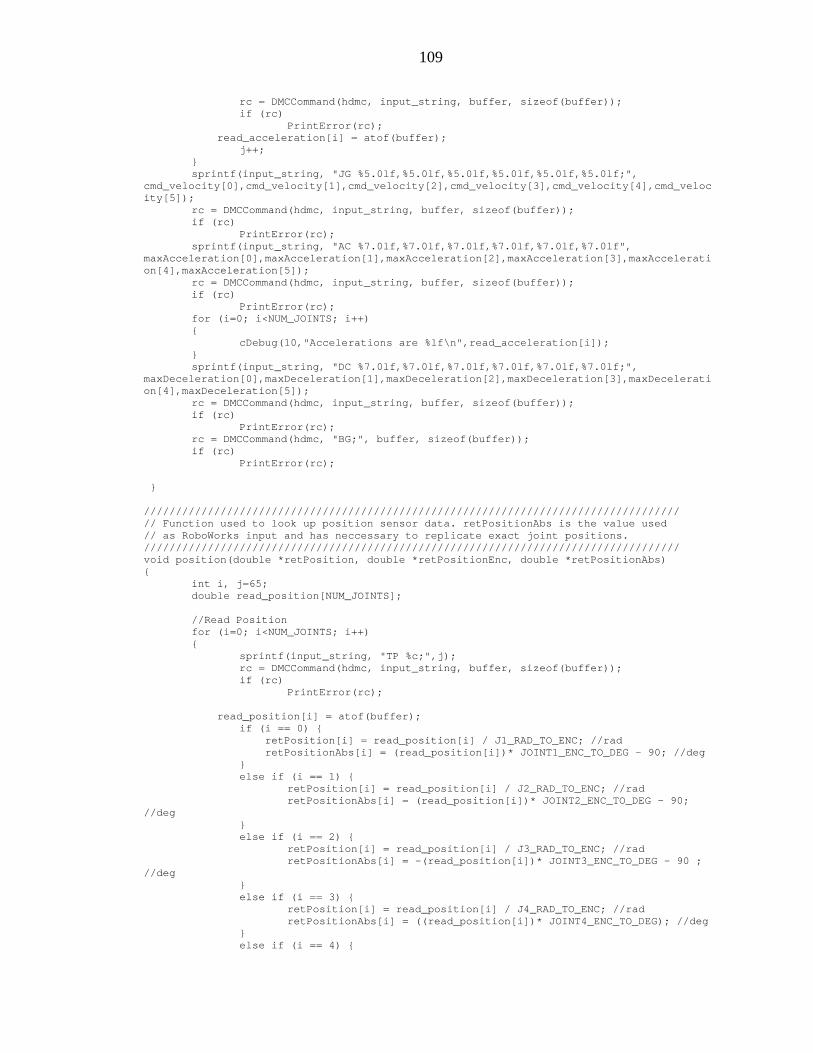
109
rc = DMCCommand(hdmc, input_string, buffer, sizeof(buffer));
ut_string, "JG %5.0lf,%5.0lf,%5.0lf,%5.0lf,%5.0lf,%5.0lf;", y[1],cmd_velocity[2],cmd_velocity[3],cmd_velocity[4],cmd_veloc
buffer, sizeof(buffer));
.0lf,%7.0lf,%7.0lf,%7.0lf,%7.0lf", cceleration[2],maxAcceleration[3],maxAccelerati
nput_string, buffer, sizeof(buffer));
(i=0
rintf nput_s ,%7.0lf,%7.0lf,%7.0lf,%7.0lf,%7.0lf;", ration [2],maxDeceleration[3],maxDecelerati
= DM ommand ing, buffer, sizeof(buffer)); (rc)
= DM sizeof(buffer)); (rc)
r
/////////////////////////////////////////////// sensor data. retPositionAbs is the value used
o replicate exact joint positions. ////////////////////////////////////////// retPositionEnc, double *retPositionAbs)
int i, j=65;
NUM_JOINTS; i++)
1) { ition[i] = read_position[i] / J2_RAD_TO_ENC; //rad
; //rad
ad_position[i] / J4_RAD_TO_ENC; //rad ((read_position[i])* JOINT4_ENC_TO_DEG); //deg
if (rc) PrintError(rc);
ration[i] = atof(buffer); read_accele j++; }
inp sprintf(d_velcm ocity[0],cmd_velocit
ity[5]); rc = DMCCommand(hdmc, input_string, if (rc) PrintError(rc); sprintf(input_string, "AC %7.0lf,%7
],maxAcceleration[1],maxAmaxAcceleration[0[4],maon xAcceleration[5]);
rc = DMCCommand(hdmc, i if (rc) PrintError(rc); for ; i<NUM_JOINTS; i++) { cDebug(10,"Accelerations are %lf\n",read_acceleration[i]); } sp (i tring, "DC %7.0lfmaxDecele [0],maxDeceleration[1],maxDecelerationon[4],maxDeceleration[5]); rc CC (hdmc, input_str if PrintError(rc); rc CCommand(hdmc, "BG;", buffer, if PrintEr or(rc); } // //////////////////////////////
to look up position /////
// Function used // as RoboWorks input and has neccessary t
//////////////////////////////////////////void position(double *retPosition, double *{ double read_position[NUM_JOINTS]; //Read Position for (i=0; i<
{ sprintf(input_string, "TP %c;",j); rc = DMCCommand(hdmc, input_string, buffer, sizeof(buffer));
(rc) if PrintError(rc);
rea positi (buffer); d_ on[i] = atof if (i == 0) {
retPosition[i] = read_position[i] / J1_RAD_TO_ENC; //rad retPositionAbs[i] = (read_position[i])* JOINT1_ENC_TO_DEG - 90; //deg
} else if (i == retPos retPositionAbs[i] = (read_position[i])* JOINT2_ENC_TO_DEG - 90; //deg } else if (i == 2) { retPosition[i] = read_position[i] / J3_RAD_TO_ENC
retPositionAbs[i] = -(read_position[i])* JOINT3_ENC_TO_DEG - 90 ; //deg } else if (i == 3) { retPosition[i] = re
i] = retPositionAbs[ }
else if (i == 4) {

110
retPosition[i] = read_position[i] / J5_RAD_TO_ENC; //rad retPositi retPositi
onAbs[i] = (read_position[i]) * JOINT5_ENC_TO_DEG ; //deg n[i] = retPosition[i] + 0.5*retPosition[i-1];
ion[i] = read_position[i] / J6_RAD_TO_ENC; //rad ionAbs[i] = (read_position[i]) * JOINT6_ENC_TO_DEG; //deg
////////////////////////////////////////////////////// elocity sensor data //////////////////////////////////////////////////////
city)
i++)
string, "TV %c;", j); , input_string, buffer, sizeof(buffer));
); f(buffer);
velocity[i] / J1_RAD_TO_ENC; //rad/s
ocity[i] = read_velocity[i] / J2_RAD_TO_ENC; //rad/s
city[i] / J3_RAD_TO_ENC; //rad/s
city[i] / J4_RAD_TO_ENC; //rad/s
retVelocity[i] = read_velocity[i] / J5_RAD_TO_ENC; //rad/s
retVelocity[i] = read_velocity[i] / J6_RAD_TO_ENC; //rad/s j++; } }
nsors built in, thus this al future implementation
th to cted below is just noise ed to magin alues.
t i, 65;
ers ; // olts
. 8; // olts
/ -lb rq [1] = 77; // -lb
o }
else { retPosit retPosit } retPositionEnc[i] = read_position[i]; //enc j++; } } //////////////////////////////// Function used to look up v//////////////////////////////
ity(double *retVelovoid veloc{ int i, j=65; //Read Velocity
M_JOINTS; for (i=0; i<NU { sprintf(input_ rc = DMCCommand(hdmc if (rc) PrintError(rc read_velocity[i] = ato if (i == 0) retVelocity[i] = read_
1) else if (i == retVel else if (i == 2) retVelocity[i] = read_velo else if (i == 3)
elocity[i] = read_velo retV else if (i == 4)
else
//////////////////////////////////////////////////////////////////////////////////// on use to loo orce/torque sensor data // Functi d k up f
// // NOTE: PUMA 762 Manipulator does not have torque se
ts sole// function exis ly as an example and for potentiystem e sensors. Data colle// on a s wi rque or forc
convert i ary torque v// //////////////////////////////////////////////////////////////////////////////////// void forcetorque(double *retForceTorque) { in j= double curr_forcetorque[NUM_JOINTS], stall_forcetorque[NUM_JOINTS];
double low_limit, high_limit, slope[NUM_JOINTS]; //Function Paramet
. 98 low_limit = -9 9 V high_limit = 9 99 V
rq e[0] = 60; / stall_forceto u 2 fto stall_forcet ue 3 ft
stall_forcetorque[2] = 294; //ft-lb stall_forcetorque[3] = 52; //ft-lb stall_forcetorque[4] = 52; //ft-lb
stall_forcetorque[5] = 24; //ft-lb //Read Torque for (i=0; i<NUM_JOINTS; i++)

111
{ curr_forcetorque[i] = 0; sprintf(input_string, "TT %c;", j);
mand(hdmc, input_string, buffer, sizeof(buffer) rc = DMCCom if (rc)
);
cetorque[i] / (high_limit - low_limit); //ft-lb/V slope[i] * curr_forcetorque[i]*FTLB_TO_NM; //Nm
////// /////// //////he Gal cont ller.
/////// ////// /////// ////// ///////
f the ALIL czIPAd ess, " 2.168
ketinfo fProto ol = Et ernetP otocolT
&hdmc);
/////
y / //////////////////////////////////////////////////
);
and(hdmc, "IN_3=@IN[3];", buffer, sizeof(buffer));
PrintError(rc);
curr_forcetorque[i] = atof(buffer); slope[i] = stall_for retForceTorque[i] = j++; } } int resetGalil(void) { rc = DMCReset(hdmc); if (rc) { PrintError(rc); return rc; } return 0; } /////////////////////////////////////// / / /////////////// // Function opening the connection to t il ro/////////////////////////////// / / / / /////// void startGALILController(void) { memset(&controllerinfo, '\0', sizeof(controllerinfo)); controllerinfo.cbSize = sizeof(controllerinfo); controllerinfo.usModelID = MODEL_2100; controllerinfo.fControllerType = ControllerTypeEthernet; controllerinfo 0 0; .ulTimeout = 10 0 controllerinfo.ulDelay = 5; // IP: 192.168.0.84 is the current IP address o G ontroller
rdware fo.so etinfo strcpy(controllerinfo.ha in ck .s dr 19 .0.84"); controllerinfo.hardwareinfo.soc . c h r CP; DMCInitLibrary(); // Open the connection rc = DMCOpen(&controllerinfo, if (rc) { PrintError(rc); galilReady = 0; } else galilReady = 1; }
//////////////////////////////////////////////////////////////////////// Check the status of the VAL II controller maintaing system checks // provided b the manufacturer. ////////////// //////////void startVALController(void) { int temp = 0; rc = DMCCommand(hdmc, "MO;", buffer, sizeof(buffer)); if (rc) PrintError(rc); rc = DMCCommand(hdmc, "OP0;", buffer, sizeof(buffer)); if (rc) PrintError(rc
rc = DMCCommand(hdmc, "AF 0,0,0,0,0,0;", buffer, sizeof(buffer)); if (rc) PrintError(rc); rc = DMCComm

112
if (rc) PrintError(rc); rc = DMCC
(rc)ommand(hdmc, "IN_3=?;", buffer, sizeof(buffer));
if PrintError(rc); else {
r); temp = atol(buffe } rc = DMCCommand(hdmc, "AT -1000;", buffer, sizeof(buffer)); if (rc)
///
ady = 1;
////// oltage ratio
orrespond to a particular index. The function further finds allowing the user to know the exact position of
y starting configuration. /////////////////////////////////////////////////////////////////////////
x)
= 0;
PrintError(rc); rc = DMCCommand(hdmc, "SH;", buffer, sizeof(buffer)); if (rc) PrintError(rc); rc = DMCCommand(hdmc, "OP1;", buffer, sizeof(buffer)); if (rc) PrintError(rc); if (temp == 0) valReady = 0; else valReady = 1; } /////////////////////////////////////////////////////////////////////////// // Check the status of the arm power (remote switch capable). ////////////////////////////////////////////////////////////////////////void startARM(void) { int temp = 0; rc = DMCCommand(hdmc, "IN_1=@IN[1];", buffer, sizeof(buffer)); if (rc) PrintError(rc); rc = DMCCommand(hdmc, "IN_1=?;", buffer, sizeof(buffer)); if (rc)
r(rc); PrintErro else {
ol(buffer); temp = at } rc = DMCCommand(hdmc, "AT -1000;", buffer, sizeof(buffer)); if (rc) PrintError(rc); if (temp == 0) armReady = 0; else armRe}
/////////////////////////////////////////////////////////////////////zation is done by checking agains the stored v// Joint initiali
values that c//// the closest index thus
the manipulator in an// //void initManipulator(long *inde{ int i, j; char k = 65; double min=0, diff[NUM_JOINTS][NUM_INDEX], pot[NUM_JOINTS], stored_ratio[NUM_JOINTS][NUM_INDEX], current_ratio[NUM_JOINTS], power[NUM_JOINTS], potpower; long pos[NUM_JOINTS], home_index[NUM_JOINTS], x=0, y=0, z=0, w=0; char index_string[32]; for (i=0; i<NUM_JOINTS; i++) { current_ratio[i] = 0;
on[i] = 1; fInMotios[i] p

113
if (i<3) home_index[i] = 35; else if (i==3) home_index[i] =
(i==4) 35;
, sizeof(buffer));
ndex_string, "JG%c=500;",k);
; g, buffer, sizeof(buffer));
EF;"); er));
1] && fInMotion[2] && fInMotion[3] &&
else if home_index[4] = 16; else
me_index[5] = 15; ho for (j=0; j<70; j++) { stored_ratio[i][j] = 0; diff[i][j] = 0; } }
tpower); averagePotPower(pot, &po for (i=0; i<NUM_JOINTS; i++) {
5) if(pot[i]>2.4 { sprintf(index_string, "JG%c=-500;",k);
ommand(hdmc, index_string, buffer rc = DMCC if (rc) PrintError(rc); } else { sprintf(i rc = DMCCommand(hdmc, index_string, buffer, sizeof(buffer)); if (rc)
PrintError(rc); } k++; } sprintf(input_string, "FI ABCDEF")
Command(hdmc, input_strin rc = DMC if (rc) PrintError(rc);
ring, "BG ABCD sprintf(input_st rc CCommand(hdmc, input_string, buffer, sizeof(buff = DM if (rc) PrintError(rc); while (!rc && fInMotion[0] && fInMotion[fInMotion[4] && fInMotion[5]) { for (i=0; i<NUM_JOINTS; i++) {
j = 65; sprintf(input_string, "MG_BG%c;", j); rc = DMCCommand(hdmc, input_string, buffer, sizeof(buffer)); if (rc) PrintError(rc); else fInMotion[i] = atoi(buffer); j++; } } rc = DMCCommand(hdmc, "AM ABCDEF", buffer, sizeof(buffer)); if (rc) PrintError(rc); rc = DMCCommand(hdmc, "HX1;", buffer, sizeof(buffer)); if (rc) PrintError(rc);
ommand
rc = CC (hdmc, "S DM P 1000,1000,1000,1000,1000,1000;", buffer, sizeof(buffer)); if (rc) PrintError(rc);

114
collectRatios(stored_ratio
);
+)
potp wer * s
j] < min)
= j; = d f[i][j
w = -3200; y 1200, w = -2000;
, y = 200, w = -800;
300, w = -700;
dmc, input_string, buffer, sizeof(buffer));
,3000,1000,1000,1000;", buffer,
////////////////////////////
r, sizeof(buffer));
k = 65; for (i=0; i<NUM_JOINTS; i++) {
min = fabs(pot[i] - power[i]); for (j=0; j<NUM_INDEX; j+
{ power[i] = o tored_ratio[i][j]; diff[i][j] = fabs(pot[i] - power[i]); if(diff[i][ { index[i] min if ]; } } if (i == 0) x = 3200, z = 3200, y = 1900, w = -1300; else if (i == 1) x = 3200, z = 3200, y = 0, else if (i == 2) x = 3200, z = 3200, =
(i == 3) else if x = 1000, z = 1000
else if (i == 4) x = 1000, z = 1000, y = 0, w = -1000; else x = 1000, z = 1000, y = if (index[i] <= home_index[i]) pos[i] = (home_index[i] - index[i]) * x + y; else pos[i] = -(index[i] - home_index[i] - 1) * z + w; sprintf(input_string, "DP%c=%ld", k, -pos[i]); rc = DMCCommand(h if (rc) PrintError(rc); k++; } rc = DMCCommand(hdmc, "SP 3000,3000sizeof(buffer)); if (rc) PrintError(rc); initialReady = 1; } ///////////////////////////////////////////////// Home the manipulator. /////////////////////////////////////////////////////////////////////////// void homeManipulator(void) { int i, j=65;
double cmd_position[NUM_JOINTS], curr_position[NUM_JOINTS]; for (i=0; i<NUM_JOINTS; i++) { fInMotion[i] = 1; sprintf(input_string, "TP %c;",j); rc = DMCCommand(hdmc, input_string, buffe if (rc) PrintError(rc); curr_position[i] = atof(buffer); cmd_position[i] = 0; if (i < 3) { if (fabs(curr_position[i]) > 112000) homeReady = 0; } else if (i == 3) { if (fabs(curr_position[i]) > 35000) homeReady = 0;

115
} else if (i == 4) { if (fabs(curr_position[i]) > 16000) homeReady = 0; } else {
[i]) > 15500) if (fabs(curr_position homeReady = 0;
buffer,
of(buffer));
Motion[2] && fInMotion[3] &&
DEF", buffer, sizeof(buffer));
///////////
++)
sprintf(input_string, "POT%c[%d]=?", k, j);
age. This Improper
/////
} j++; } rc = DMCCommand(hdmc, "SP 3000,3000,3000,1000,1000,1000;", sizeof(buffer)); if (rc) PrintError(rc); sprintf(input_string, "PA 0,0,0,0,0,0;");
uffer, size rc = DMCCommand(hdmc, input_string, b if (rc) PrintError(rc);
sprintf(input_string, "BG ABCDEF;"); ; rc = DMCCommand(hdmc, input_string, buffer, sizeof(buffer))
if (rc) PrintError(rc); while (!rc && fInMotion[0] && fInMotion[1] && fInfInMotion[4] && fInMotion[5]) { for (i=0; i<NUM_JOINTS; i++) { j = 65; sprintf(input_string, "MG_BG%c;", j); rc = DMCCommand(hdmc, input_string, buffer, sizeof(buffer)); if (rc) PrintError(rc); else
fInMotion[i] = atoi(buffer); j++; } }
nd(hdmc, "AM ABC rc = DMCComma if (rc) PrintError(rc); homeReady = 1; } ////////////////////////////////////////////////////////////////// Obtain voltage ratio values of the Galil EEPROM // // ////////////////////////////////////////////////////////////
s(double stored_ratio[NUM_JOINTS][NUM_INDEX]) ///// //////
void collectRatio{ int i, j, k = 65;
NUM_JOINTS; i for (i=0; i< {
; j<NUM_INDEX; j++) for (j=0 { rc = DMCCommand(hdmc, input_string, buffer, sizeof(buffer)); if (rc) PrintError(rc); stored_ratio[i][j]=atof(buffer); } k+ +; } } /////////////////////////////////////////////////////////////////////////// // ute the average of one hundred Comp queries to the current volt// is neccessary due to the voltage fluctuations caused by noise. // values could cause initilization to be slightly off. //////////////////////////////////////////////////////////////////////

116
void averagePotPower(double *pot, double *potpower) { double pott[NUM_JOINTS], temp[7], power; int i, j; power = 0;
for(i=0; i<7; i++) { if (i<6)
id Pri
(
pott[i] = 0; if (i<7) temp[i] = 0; } for (i=0; i<100; i++) { for (j=1; j<8; j++) { sprintf(input_string, "AN_%d=@AN[%d]",j ,j);
rc = DMCCommand(hdmc, input_string, buffer, sizeof(buffer)); if (rc)
PrintError(rc); sprintf(input_string, "AN_%d=?", j); rc = DMCCommand(hdmc, input_string, buffer, sizeof(buffer)); if (rc) PrintError(rc); temp[j-1]=atof(buffer); if(j<7)
pott[j-1]+=temp[j-1];
else power += temp[j-1]; } } for (j=0; j<NUM_JOINTS; j++) { pot[j]=pott[j]/100; } *potpower=power/100; } vo ntError(long rc) { fflush(stdout); } ///////////////////////////////////////////////////////////////////////////////////////// // File: galilInterface.h // Version: 0.1 Original Creation // Written by: Ognjen Sosa ([email protected]) // Date: 09/28/2004 // // Description: This file contains function prototypes required for galilInterface.c ///////////////////////////////////////////////////////////////////////////////////////// #ifndef __GALILINTERFACE_H_ #define __GALILINTERFACE_H_ #define NUM_JOINTS 6 #define NUM_INDEX 70 #define INTERFACE_THREAD_TIMEOUT_SEC 1.0 //public int interfaceStartup(void); int interfaceShutdown(void); void *interfaceThread(void *threadData);
aceUpdateRate void); double getInterfint getInterfaceThreadRunning(void);

117
//private accessors int setEffort(double *); double getJointCmdEffort(int); double getJointRealEffort(int); double getJointPosition(int); double getJointVelocity(int); double getJointForceTorque(int); int getGalilReady(void); int getValReady(void); int getArmReady(void); int getInitialize(void); int getPumaHome (void); int getInterfaceReady(void); double g
id se
id po oubl *);
id co 70]);
////////////// File
Creation
C code for implementation of a Primitive
///// ////// //
: JAUS libraries
nk
JAUS
etTimeSeconds(void); //private int resetGalil(void); void startGALILController(void); void startVALController(void); void startARM(void);
ator(long *); void initManipulvoid homeManipulator(void); void setMaxSpeed(double *); void setMaxAcceleration(double *);vo tMaxDeceleration(double *);void motion(double *, double *); vo sition(double *, double *,d evoid velocity(double *); void forcetorque(double *); void averagePotPower(double *, double *); vo llectRatios(double stored_ratio[6][void PrintError(long rc); #endif
B.2 The Pm.c File and the Corresponding Header Pm.h
/////// ////// /// / //////////////////////////////////////////////////////////// : pm.c
.1 Original// Version: 0// Written by: Ognjen Sosa ([email protected])
[email protected]) // Template by: Tom Galluzzo (9/28/2004 // Date: 0
/ /This file contains the // Description:
/ / Manipulator JAUS component in a Linux environment. This code is // designed to work with the node manager and JAUS library software / / written by Jeff Witt.
// // ////////////////////////////////////////////////////////////////////////
// JAUS message set (USER#include <jaus.h> must be installed first) #include <pthread.h> // Multi-threading functions (standard to unix) #include <timeLib.h> // Precise timing routines (USER: must litimeLib.c, written by Tom Galluzzo) #include <unistd.h> // Unix standard functions #include <stdio.h> // Unix standard input-output #include <math.h> // Mathematical functions
ns for sending and receiving#include <nodemgr/nodemgr.h> // Node managment functioager must be installed) messages (USER: Node Man
#include "pm.h" // File containing all function and accessor defintions used in this component

118
#include "galilInterfaceio
.h" // Access to setEffort() and getJointPosition() funct ns#include "logLib.h" // Debug definitions #include "mcConstants.h" #define DATASIZE JDATASIZE // Default size for byte stream buffers in this file // Private function prototypes void *pmStateThread(void *); void *pmNodemgrThread(void *); // State messages set by this component void pmStandbySsc(void); void pmResumeSsc(void); // Accessor to incoming information jointEffort_t * pmSetJointEffort(void); joint efforts
// Accessor to the value of
latorSpecifications(void);
US Instance, Node and
// JAUS Authority for this
// JAUS State, running
//
identity of the component
es the
not is nder c
case SET_JOINT EFFORT
eci icatio
nager JAUS Message Service (Jms) for this
blic tracted component functionality contained in rce.
y one call
r the component threads spawned in
// Accessors to outgoing information jointEffort_t * pmReportJointEffort(void);
ManipumanipulatorSpecifications_t * pmReport unsigned char pmInstId, pmNodeId, pmSubsId; // JASubsystem IDs for this component componentAuthority_t pmAuthority = 0; component int pmState = SHUTDOWN_STATE; State, and a thread running count double pmThreadHz; Stores the calculated update rate for main state thread unsigned char pmCtrlCmptInstId, pmCtrlCmptCompId; // Stores currently in control unsigned char pmCtrlCmptNodeId, pmCtrlCmptSubsId; // Stores identity of the component currently in control unsigned char pmCtrlCmptAuthority; // Storauthority level of the component currently in control
t pmU erCont l = F SE; in nd ro AL // FALSE - under control, TRUE u ontrol int pmRun = FALSE; int pmStateThreadRunning = FALSE; pthread_t pmStateThreadId; int pmNodemgrThreadRunning = FALSE;
Thr dId; pthread_t pmNodemgr ea // Structure storing incoming request under static jointEffort_t setJointEffort; // Structure defining data received and sent by this component // Structure storing incoming request under case QUERY JOINT EFFORT static jointEffort_t reportedJointEffort; // Structure storing incoming request under case QUERY MANIPULATOR SPECIFICATIONS static manipulatorSp f ns_t reportedManipulatorSpecifications;
ode Majms_t pmJms; // An accessor to the Ncomponent // Function: pmStartup // Access: Pu // Description: This function allows the absthis file to be started from an external sou// It must be called first before the component state machine and node manager interaction will begin // Each call to "cmptStartup" should be followed bto the "cmptShutdown" function int pmStartup(void) { pthread_attr_t attr; // Thread attributed fothis function

119
if(pmState == SHUTDOWN_STATE) // Execute the startup routines only component is not running
if the
d Subsystem
r
jmsRecv,
mptNodemgrThread\n");
EATE_ERROR;
close the Jms connection to the
{ n Instance, Node an // Check in to the Node Manager and obtai
IDs if(jcmCheckIn(PRIMITIVE_MANIPULATOR, &pmInstId, &pmNodeId, &pmSubsId) < 0) // USER: Insert your component ID define on this line { cError("pm: Could not check in to nodemgr\n"); return PM_NODE_MANAGER_CHECKIN_ERROR; } // Open a conection to the Node Manager and obtain a Jms accessor if((pmJms = jmsOpen(PRIMITIVE_MANIPULATOR, pmInstId, 0)) == NULL) // USER: Insert your component ID define on this line { jcmCheckOut(PRIMITIVE_MANIPULATOR, pmInstId); // USER: Insert youcomponent ID define on this line return PM_JMS_OPEN_ERROR; } pmJms->timeout.tv_usec = 100000; // Timeout for non-blocking specified in micro seconds pthread_attr_init(&attr); pthread_attr_setdetachstate(&attr, PTHREAD_CREATE_DETACHED); // Set the state of the JAUS state machine to INITIALIZE pmState = INITIALIZE_STATE; pmRun = TRUE;
= 0 if(pthread_create(&pmStateThreadId, &attr, pmStateThread, NULL) ! ) { cError("pm: Could not create cmptStateThread\n"); pmShutdown(); return PM_STATE_THREAD_CREATE_ERROR; } if(pthread_create(&pmNodemgrThreadId, &attr, pmNodemgrThread, NULL) != 0) { cError("pm: Could not create c pmShutdown(); return PM_NODEMGR_THREAD_CR } pthread_attr_destroy(&attr); } else { cError("pm: Attempted startup while not shutdown\n"); return PM_STARTUP_BEFORE_SHUTDOWN_ERROR; } return 0; } // Function: pmShutdown // Access: Public // Description: This function allows the abstracted component functionality contained in this file to be stoped from an external source. // If the component is in the running state, this function will terminate all threads running in this file // This function will also Node Manager and check out the component from the Node Manager
tdown( id) int pmShu vo{ double timeOutSec; double effort[NUM_JOINTS]; int i;

120
if (pmState != SHUTDOWN_STATE) // Execute the startup routines only if the component is not running { pmRun = FALSE; timeOutSec = getTimeSeconds() + PM_THREAD_TIMEOUT_SEC; while(pmStateThreadRunning) { usleep(100000); if(getTimeSeconds() >= timeOutSec) { pthread_cancel(pmStateThreadId); pmStateThreadRunning = FALSE;
Shutdown cError("pm: cmptStateThread break;
Improperly\n");
OUT_SEC;
dRunning = FALSE; ptNodemgrThread Shutdown Improperly\n");
minating possibility of jerky motion
ATOR, pmInstId); // USER: Insert your
igned char)PRIMITIVE_MANIPULATOR; }
te( oid){
urn &setJointEffort; } return &reportedJointEffort; }
ions(void) { return
ty is contained in this thread. nt state machine code can be found
} } timeOutSec = getTimeSeconds() + PM_THREAD_TIME
while(pmNodemgrThreadRunning) { usleep(100000); if(getTimeSeconds() >= timeOutSec) { pthread_cancel(pmNodemgrThreadId); pmNodemgrThrea cError("pm: cm break; } } // Set jog values to zero eli for (i=0; i<NUM_JOINTS; i++) { effort[i] = 0; } setEffort(effort); // Set the state of the subsystem commander to standby pmStandbySsc(); // Close Node Manager Connection and check out jmsClose(pmJms); jcmCheckOut(PRIMITIVE_MANIPULcomponent ID define on this line pmState = SHUTDOWN_STATE; } return 0; } // The series of functions below allow public access to essential component information // Access: Public (All) int pmGetState(void){ return pmState; }
pmInstId; } unsigned char pmGetInstanceId(void){ return n (unsunsigned char pmGetCompId(void){ retur
unsigned char pmGetNodeId(void){ return pmNodeId; } unsigned char pmGetSubsystemId(void){ return pmSubsId; } double pmGetUpdateRa v return pmThreadHz; } jointEffort_t * pmSetJointEffort(void) { retjointEffort_t * pmReportJointEffort(void) { manipulatorSpecifications_t * pmReportManipulatorSpecificat&reportedManipulatorSpecifications; } // Function: pmThread // Access: Private // Description: All core component functionali// All of the JAUS componehere. void *pmStateThread(void *threadData)

121
{ jmh_t txMsgHeader; unsigned char data[DATASIZE];
uble me, pr do ti evTime, effort[NUM_JOINTS], curr_position[NUM_JOINT in
S]; t i;
tion
US state to INITIALIZE
e code while not in the SHUTDOWN state
= time;
se INITIALIZE_STATE: // Check for system initialization
terfaceReady()) { tate = READY_STATE;
else pmState = STANDBY_STATE; break;
break;
mmander if in standby mode
o the manipulator interface edJointEffort.numJoints = NUM_JOINTS;
for(i=0; i<NUM_JOINTS; i++)
ointEffort.jointEffort[i] =
effort[i] = setJointEffort.jointEffort[i];
setEffort(effort);
ittle lower
if (i < 5) { if (fabs(curr_position[i]) >
fications.jointSpecifications[i].jointMaximumValue / 1000) pmState = EMERGENCY_STATE;
pmStateThreadRunning = TRUE; // // Setup transmit header txMsgHeader.isExpMsg = 0; // not experimental msg - USER: change to 1 if experimental txMsgHeader.isSvcMsg = 0; // not a service connec txMsgHeader.acknCtrl = 0; // no ack/nak txMsgHeader.priority = 6; // default priority txMsgHeader.reserved = 0; txMsgHeader.version = 1; // JAUS 3.0 txMsgHeader.srcInstId = pmInstId; txMsgHeader.srcCompId = PRIMITIVE_MANIPULATOR; txMsgHeader.srcNodeId = pmNodeId; txMsgHeader.srcSubsId = pmSubsId; txMsgHeader.dataCtrl = 0; txMsgHeader.seqNumber = 0; time = getTimeSeconds(); pmState = INITIALIZE_STATE; // Set JA while(pmRun) // Execute state machin { prevTime
me = getTimeSeconds(); ti pmThreadHz = 1.0/(time-prevTime); // Compute the update rate of this thread
switch(pmState) // Switch component behavior based on which state the machine is in {
ca if(getIn pmS } case STANDBY_STATE: case READY_STATE: // Resume system co pmResumeSsc();
mand effort t // Com report { reportedJgetJointRealEffort(i); } // Set up fail-safe with software limits a lthan mechanical limits for (i=0; i<NUM_JOINTS; i++) {
curr_position[i] = getJointPosition(i);
reportedManipulatorSpeci
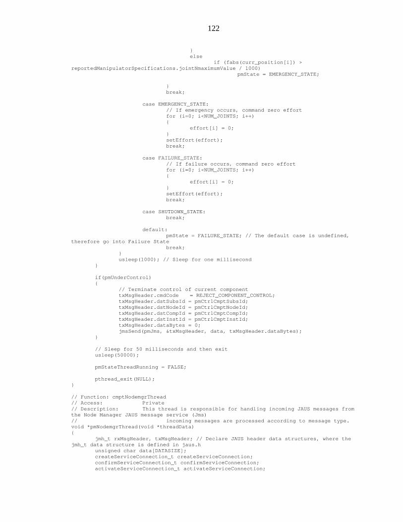
122
e
} se
f (fabs(curr_position[i]) > mValue / 1000)
pmState = EMERGENCY_STATE;
} break; case EMERGENCY_STATE: // If emergency occurs, command zero effort for (i=0; i<NUM_JOINTS; i++) { effort[i] = 0; } setEffort(effort); break; case FAILURE_STATE: // If failure occurs, command zero effort for (i=0; i<NUM_JOINTS; i++) { effort[i] = 0; } setEffort(effort); break; case SHUTDOWN_STATE: break; default: pmState = FAILURE_STATE; // The default case is undefined, therefore go into Failure State break; } usleep(1000); // Sleep for one millisecond } if(pmUnderControl) { // Terminate control of current component txMsgHeader.cmdCode = REJECT_COMPONENT_CONTROL; txMsgHeader.dstSubsId = pmCtrlCmptSubsId; txMsgHeader.dstNodeId = pmCtrlCmptNodeId; txMsgHeader.dstCompId = pmCtrlCmptCompId; txMsgHeader.dstInstId = pmCtrlCmptInstId; txMsgHeader.dataBytes = 0; jmsSend(pmJms, &txMsgHeader, data, txMsgHeader.dataBytes); } // Sleep for 50 milliseconds and then exit usleep(50000); pmStateThreadRunning = FALSE; pthread_exit(NULL); } // Function: cmptNodemgrThread // Access: Private // Description: This thread is responsible for handling incoming JAUS messages from the Node Manager JAUS message service (Jms) // incoming messages are processed according to message type. void *pmNodemgrThread(void *threadData) { jmh_t rxMsgHeader, txMsgHeader; // Declare JAUS header data structures, where the jmh_t data structure is defined in jaus.h unsigned char data[DATASIZE]; createServiceConnection_t createServiceConnection; confirmServiceConnection_t confirmServiceConnection; activateServiceConnection_t activateServiceConnection;
l ire dManipulatorSpecifications.jointNmaximu
porte
123
suspendServiceConnection_t suspendServiceConnection; terminateServiceConnection_t terminateServiceConnection; requestComponentControl_t requestComponentControl; confirmComponentControl_t confirmComponentControl; componentAuthority_t componentAuthority; componentStatus_t componentStatus; int recvCount; pmNodemgrThreadRunning = TRUE; // Increment the number of threads running in this file // Setup Manipulator Specifications reportedManipulatorSpecifications.numJoints = NUM_JOINTS; reportedManipulatorSpecifications.jointNtype = 1; reportedManipulatorSpecifications.jointNoffsetOrAngle = 129; //mm reportedManipulatorSpecifications.jointNminimumValue = 0 / J6_RAD_TO_ENC * 1000; //10^-3 rad reportedManipulatorSpecifications.jointNmaximumValue = 31000 / J6_RAD_TO_ENC * 1000; //10^-3 rad reportedManipulatorSpecifications.jointNmaximumVelocity = 1000 / J6_RAD_TO_ENC * 1000;//10^-3 rad/sec reportedManipulatorSpecifications.manipulatorCoordinateSystemX = 0; reportedManipulatorSpecifications.manipulatorCoordinateSystemY = 0; reportedManipulatorSpecifications.manipulatorCoordinateSystemZ = 0; reportedManipulatorSpecifications.quaternionQcomponentD = 1; reportedManipulatorSpecifications.quaternionQcomponentA = 0; reportedManipulatorSpecifications.quaternionQcomponentB = 0; reportedManipulatorSpecifications.quaternionQcomponentC = 0; reportedManipulatorSpecifications.jointSpecifications[0].jointType = 1; reportedManipulatorSpecifications.jointSpecifications[0].linkLength = 0.0; //mm reportedManipulatorSpecifications.jointSpecifications[0].twistAngle = 90 * DEG_TO_RAD * 1000; //10^-3 rad reportedManipulatorSpecifications.jointSpecifications[0].jointOffsetOrAngle = 0; //mm reportedManipulatorSpecifications.jointSpecifications[0].jointMinimumValue = 0 / J1_RAD_TO_ENC * 1000; //10^-3 rad reportedManipulatorSpecifications.jointSpecifications[0].jointMaximumValue = 224000 / J1_RAD_TO_ENC * 1000; //10^-3 rad reportedManipulatorSpecifications.jointSpecifications[0].jointMaximumVelocity = 5000 / J1_RAD_TO_ENC * 1000; //10^-3 rad/sec reportedManipulatorSpecifications.jointSpecifications[1].jointType = 1; reportedManipulatorSpecifications.jointSpecifications[1].linkLength = 650; //mm reportedManipulatorSpecifications.jointSpecifications[1].twistAngle = 0; //10^-3 rad reportedManipulatorSpecifications.jointSpecifications[1].jointOffsetOrAngle = 190;//mm reportedManipulatorSpecifications.jointSpecifications[1].jointMinimumValue = 0 / J2_RAD_TO_ENC * 1000; //10^-3 rad reportedManipulatorSpecifications.jointSpecifications[1].jointMaximumValue = 224000 / J2_RAD_TO_ENC * 1000; //10^-3 rad reportedManipulatorSpecifications.jointSpecifications[1].jointMaximumVelocity = 5000 / J2_RAD_TO_ENC * 1000; //10^-3 rad/sec reportedManipulatorSpecifications.jointSpecifications[2].jointType = 1; reportedManipulatorSpecifications.jointSpecifications[2].linkLength = 0.0;//mm reportedManipulatorSpecifications.jointSpecifications[2].twistAngle = 270 * DEG_TO_RAD * 1000; //10^-3 rad reportedManipulatorSpecifications.jointSpecifications[2].jointOffsetOrAngle = 0; //mm reportedManipulatorSpecifications.jointSpecifications[2].jointMinimumValue = 0 / J3_RAD_TO_ENC * 1000; //10^-3 rad reportedManipulatorSpecifications.jointSpecifications[2].jointMaximumValue = 224000 / J3_RAD_TO_ENC * 1000;//10^-3 rad reportedManipulatorSpecifications.jointSpecifications[2].jointMaximumVelocity = 5000 / J3_RAD_TO_ENC * 1000; //10^-3 rad/sec reportedManipulatorSpecifications.jointSpecifications[3].jointType = 1; reportedManipulatorSpecifications.jointSpecifications[3].linkLength = 0.0; //mm
124
reportedManipulatorSpecifications.jointSpecifications[3].twistAngle = 90 * DEG_TO_RAD * 1000; //10^-3 rad reportedManipulatorSpecifications.jointSpecifications[3].jointOffsetOrAngle = 600; //mm reportedManipulatorSpecifications.jointSpecifications[3].jointMinimumValue = 0 / J4_RAD_TO_ENC * 1000; //10^-3 rad reportedManipulatorSpecifications.jointSpecifications[3].jointMaximumValue = 70000 / J4_RAD_TO_ENC * 1000; //10^-3 rad reportedManipulatorSpecifications.jointSpecifications[3].jointMaximumVelocity = 1000 / J4_RAD_TO_ENC * 1000; //10^-3 rad/sec reportedManipulatorSpecifications.jointSpecifications[4].jointType = 1; reportedManipulatorSpecifications.jointSpecifications[4].linkLength = 0.0; //mm reportedManipulatorSpecifications.jointSpecifications[4].twistAngle = 90 * DEG_TO_RAD * 1000; //10^-3 rad reportedManipulatorSpecifications.jointSpecifications[4].jointOffsetOrAngle = 0; //mm reportedManipulatorSpecifications.jointSpecifications[4].jointMinimumValue = 0 / J5_RAD_TO_ENC * 1000; //10^-3 rad reportedManipulatorSpecifications.jointSpecifications[4].jointMaximumValue = 32000 / J5_RAD_TO_ENC * 1000; //10^-3 rad reportedManipulatorSpecifications.jointSpecifications[4].jointMaximumVelocity = 1000 / J5_RAD_TO_ENC * 1000; //10^-3 rad/sec // Setup transmit header txMsgHeader.isExpMsg = 0; // not experimental msg - USER: change to 1 if experimental txMsgHeader.isSvcMsg = 0; // not a service connection txMsgHeader.acknCtrl = 0; // no ack/nak txMsgHeader.priority = 6; // default priority txMsgHeader.reserved = 0; txMsgHeader.version = 1; // JAUS 3.0 txMsgHeader.srcInstId = pmInstId; txMsgHeader.srcCompId = PRIMITIVE_MANIPULATOR; txMsgHeader.srcNodeId = pmNodeId; txMsgHeader.srcSubsId = pmSubsId; txMsgHeader.dataCtrl = 0; txMsgHeader.seqNumber = 0; while(pmRun) // Execute incoming JAUS message processing while not in the SHUTDOWN state { // Check for a new message in the Node Manager JMS queue // If a message is present then store the header information in rxMsgHeader, and store the message content information in the data buffer recvCount = jmsRecv(pmJms, &rxMsgHeader, data, DATASIZE); if (recvCount < 0) { cError("pm: Node manager jmsRecv returned error: %d\n", recvCount); break; } if (recvCount == 0) continue; // This block of code is intended to reject commands from non-controlling components // However, the one exception allowed is a REQUEST_COMPONENT_CONTROL if(pmUnderControl && rxMsgHeader.cmdCode < 0x2000) // If not currently under control or it's not a command, then go to the switch statement { // If the source component isn't the one in control, and it's not a request to gain control, then exit this iteration of the while loop if(!(pmCtrlCmptInstId==rxMsgHeader.srcInstId && pmCtrlCmptCompId==rxMsgHeader.srcCompId && pmCtrlCmptNodeId==rxMsgHeader.srcNodeId && pmCtrlCmptSubsId==rxMsgHeader.srcSubsId)&& !(rxMsgHeader.cmdCode==REQUEST_COMPONENT_CONTROL) )continue; // to next iteration } switch(rxMsgHeader.cmdCode) // Switch the processing algorithm according to the JAUS message type

125
{ // Set the component authority according to the incoming authority code case SET_COMPONENT_AUTHORITY: convertComponentAuthority(data, &pmAuthority, DATASIZE, UNPACK); // Unpack and store the incoming authority code break; case SHUTDOWN: pmState = SHUTDOWN_STATE; break; case STANDBY: if(pmState == READY_STATE) pmState = STANDBY_STATE; break; case RESUME: if(pmState == STANDBY_STATE) pmState = READY_STATE; break; case RESET: pmState = INITIALIZE_STATE; break; case SET_EMERGENCY: pmState = EMERGENCY_STATE; break; case CLEAR_EMERGENCY: pmState = STANDBY_STATE; break; case CREATE_SERVICE_CONNECTION: convertCreateServiceConnection(data, &createServiceConnection, DATASIZE, UNPACK); // USER: Insert code here to handle the create service connection message break; case CONFIRM_SERVICE_CONNECTION: convertConfirmServiceConnection(data, &confirmServiceConnection, DATASIZE, UNPACK); // USER: Insert code here to handle the confirm service connection message break; case ACTIVATE_SERVICE_CONNECTION: convertActivateServiceConnection(data, &activateServiceConnection, DATASIZE, UNPACK); // USER: Insert code here to handle the activate service connection message break; case SUSPEND_SERVICE_CONNECTION: convertSuspendServiceConnection(data, &suspendServiceConnection, DATASIZE, UNPACK); // USER: Insert code here to handle the suspend service connection message break; case TERMINATE_SERVICE_CONNECTION: convertTerminateServiceConnection(data, &terminateServiceConnection, DATASIZE, UNPACK); // USER: Insert code here to handle the terminate service connection message break; case REQUEST_COMPONENT_CONTROL:
126
convertRequestComponentControl(data, &requestComponentControl, DATASIZE, UNPACK); if(pmUnderControl) { if(requestComponentControl > pmCtrlCmptAuthority) // Test for higher authority { // Terminate control of current component txMsgHeader.cmdCode = REJECT_COMPONENT_CONTROL; txMsgHeader.dstSubsId = pmCtrlCmptSubsId; txMsgHeader.dstNodeId = pmCtrlCmptNodeId; txMsgHeader.dstCompId = pmCtrlCmptCompId; txMsgHeader.dstInstId = pmCtrlCmptInstId; txMsgHeader.dataBytes = 0; jmsSend(pmJms, &txMsgHeader, data, txMsgHeader.dataBytes); // Accept control of new component txMsgHeader.cmdCode = CONFIRM_COMPONENT_CONTROL; txMsgHeader.dstSubsId = rxMsgHeader.srcSubsId; txMsgHeader.dstNodeId = rxMsgHeader.srcNodeId; txMsgHeader.dstCompId = rxMsgHeader.srcCompId; txMsgHeader.dstInstId = rxMsgHeader.srcInstId; confirmComponentControl.asByte = 0; txMsgHeader.dataBytes = convertConfirmComponentControl(data, &confirmComponentControl, DATASIZE, PACK); jmsSend(pmJms, &txMsgHeader, data, txMsgHeader.dataBytes); pmCtrlCmptInstId = rxMsgHeader.srcInstId; pmCtrlCmptCompId = rxMsgHeader.srcCompId; pmCtrlCmptNodeId = rxMsgHeader.srcNodeId; pmCtrlCmptSubsId = rxMsgHeader.srcSubsId; pmCtrlCmptAuthority = requestComponentControl; } else { if( rxMsgHeader.srcSubsId != pmCtrlCmptSubsId || rxMsgHeader.srcNodeId != pmCtrlCmptNodeId || rxMsgHeader.srcCompId != pmCtrlCmptCompId || rxMsgHeader.srcInstId != pmCtrlCmptInstId ) { txMsgHeader.cmdCode = REJECT_COMPONENT_CONTROL; txMsgHeader.dstSubsId = rxMsgHeader.srcSubsId; txMsgHeader.dstNodeId = rxMsgHeader.srcNodeId; txMsgHeader.dstCompId = rxMsgHeader.srcCompId; txMsgHeader.dstInstId = rxMsgHeader.srcInstId; txMsgHeader.dataBytes = 0; jmsSend(pmJms, &txMsgHeader, data, txMsgHeader.dataBytes); } } } else // Not currently under component control, so give control { txMsgHeader.cmdCode = CONFIRM_COMPONENT_CONTROL; txMsgHeader.dstSubsId = rxMsgHeader.srcSubsId; txMsgHeader.dstNodeId = rxMsgHeader.srcNodeId;

127
txMsgHeader.dstCompId = rxMsgHeader.srcCompId; txMsgHeader.dstInstId = rxMsgHeader.srcInstId; confirmComponentControl.asByte = 0; txMsgHeader.dataBytes = convertConfirmComponentControl(data, &confirmComponentControl, DATASIZE, PACK); jmsSend(pmJms, &txMsgHeader, data, txMsgHeader.dataBytes); pmCtrlCmptInstId = rxMsgHeader.srcInstId; pmCtrlCmptCompId = rxMsgHeader.srcCompId; pmCtrlCmptNodeId = rxMsgHeader.srcNodeId; pmCtrlCmptSubsId = rxMsgHeader.srcSubsId; pmCtrlCmptAuthority = requestComponentControl; pmUnderControl = TRUE; } break; case RELEASE_COMPONENT_CONTROL: pmUnderControl = FALSE; break; case CONFIRM_COMPONENT_CONTROL: convertConfirmComponentControl(data, &confirmComponentControl, DATASIZE, UNPACK); // USER: Insert code here to handle the confirm component control message if needed break; case REJECT_COMPONENT_CONTROL: // USER: Insert code here to handle the reject component control message if needed break; case QUERY_COMPONENT_AUTHORITY: txMsgHeader.cmdCode = REPORT_COMPONENT_AUTHORITY; txMsgHeader.dstSubsId = rxMsgHeader.srcSubsId; txMsgHeader.dstNodeId = rxMsgHeader.srcNodeId; txMsgHeader.dstCompId = rxMsgHeader.srcCompId; txMsgHeader.dstInstId = rxMsgHeader.srcInstId; componentAuthority = pmAuthority; txMsgHeader.dataBytes = convertComponentAuthority(data, &componentAuthority, DATASIZE, PACK); jmsSend(pmJms, &txMsgHeader, data, txMsgHeader.dataBytes); break; case QUERY_COMPONENT_STATUS: txMsgHeader.cmdCode = REPORT_COMPONENT_STATUS; txMsgHeader.dstSubsId = rxMsgHeader.srcSubsId; txMsgHeader.dstNodeId = rxMsgHeader.srcNodeId; txMsgHeader.dstCompId = rxMsgHeader.srcCompId; txMsgHeader.dstInstId = rxMsgHeader.srcInstId; componentStatus.primaryStatus.asByte = pmState; txMsgHeader.dataBytes = convertComponentStatus(data, &componentStatus, DATASIZE, PACK); jmsSend(pmJms, &txMsgHeader, data, txMsgHeader.dataBytes); break; case REPORT_COMPONENT_AUTHORITY: convertComponentAuthority(data, &componentAuthority, DATASIZE, UNPACK); // USER: Insert code here to handle the report component authority message if needed break; case REPORT_COMPONENT_STATUS: convertComponentStatus(data, &componentStatus, DATASIZE, UNPACK); break; case SET_JOINT_EFFORT: convertJointEffort(data, &setJointEffort, DATASIZE, UNPACK);

128
break; case QUERY_JOINT_EFFORT: txMsgHeader.cmdCode = REPORT_JOINT_EFFORT; txMsgHeader.dstInstId = rxMsgHeader.srcInstId; txMsgHeader.dstCompId = rxMsgHeader.srcCompId; txMsgHeader.dstNodeId = rxMsgHeader.srcNodeId; txMsgHeader.dstSubsId = rxMsgHeader.srcSubsId; txMsgHeader.dataBytes = convertJointEffort(data, &reportedJointEffort, DATASIZE, PACK); jmsSend(pmJms, &txMsgHeader, data, txMsgHeader.dataBytes); break; case QUERY_MANIPULATOR_SPECIFICATIONS: // unpack presence vector txMsgHeader.cmdCode = REPORT_MANIPULATOR_SPECIFICATIONS; txMsgHeader.dstSubsId = rxMsgHeader.srcSubsId; txMsgHeader.dstNodeId = rxMsgHeader.srcNodeId; txMsgHeader.dstCompId = rxMsgHeader.srcCompId; txMsgHeader.dstInstId = rxMsgHeader.srcInstId; txMsgHeader.dataBytes = convertManipulatorSpecifications(data, &reportedManipulatorSpecifications, DATASIZE, PACK); jmsSend(pmJms, &txMsgHeader, data, txMsgHeader.dataBytes); break; default: break; } } pmNodemgrThreadRunning = FALSE; pthread_exit(NULL); } void pmStandbySsc(void) { jmh_t txMsg; unsigned char data[DATASIZE]; double requestTimeOutSec = 0.1; static double lastRequestTimeSec = 0; // Setup Transmit msg txMsg.isExpMsg = 0; txMsg.priority = 6; txMsg.acknCtrl = 0; txMsg.isSvcMsg = 0; txMsg.version = 1; txMsg.reserved = 0; txMsg.srcInstId = pmInstId; txMsg.srcCompId = PRIMITIVE_MANIPULATOR; txMsg.srcNodeId = pmNodeId; txMsg.srcSubsId = pmSubsId; txMsg.dataCtrl = 0; txMsg.seqNumber = 0; txMsg.cmdCode = STANDBY; txMsg.dstInstId = 1; txMsg.dstCompId = SUBSYSTEM_COMMANDER; txMsg.dstNodeId = pmNodeId; txMsg.dstSubsId = pmSubsId ; txMsg.dataBytes = 0; if( (getTimeSeconds() - lastRequestTimeSec) >= requestTimeOutSec) { jmsSend(pmJms, &txMsg, data, txMsg.dataBytes); lastRequestTimeSec = getTimeSeconds(); } } void pmResumeSsc(void) {
129
jmh_t txMsg; unsigned char data[DATASIZE]; double requestTimeOutSec = 0.1; static double lastRequestTimeSec = 0; // Setup Transmit msg txMsg.isExpMsg = 0; txMsg.priority = 6; txMsg.acknCtrl = 0; txMsg.isSvcMsg = 0; txMsg.version = 1; txMsg.reserved = 0; txMsg.srcInstId = pmInstId; txMsg.srcCompId = PRIMITIVE_MANIPULATOR; txMsg.srcNodeId = pmNodeId; txMsg.srcSubsId = pmSubsId; txMsg.dataCtrl = 0; txMsg.seqNumber = 0; txMsg.cmdCode = RESUME; txMsg.dstInstId = 1; txMsg.dstCompId = SUBSYSTEM_COMMANDER; txMsg.dstNodeId = pmNodeId; txMsg.dstSubsId = pmSubsId ; txMsg.dataBytes = 0; if( (getTimeSeconds() - lastRequestTimeSec) >= requestTimeOutSec) { jmsSend(pmJms, &txMsg, data, txMsg.dataBytes); lastRequestTimeSec = getTimeSeconds(); } } ///////////////////////////////////////////////////////////////////////////////////////// // File: pm.h // Version: 0.1 Original Creation // Written by: Ognjen Sosa ([email protected]) // Template by: Tom Galluzzo ([email protected]) // Date: 09/28/2004 // // Description: This file contains the skeleton C header file code for implementing // the pm.c file ///////////////////////////////////////////////////////////////////////////////////////// #ifndef PM_H #define PM_H #include "jaus.h" #ifndef FALSE #define FALSE 0 #endif #ifndef TRUE #define TRUE 1 #endif #define PM_NODE_MANAGER_CHECKIN_ERROR -1 #define PM_JMS_OPEN_ERROR -2 #define PM_STARTUP_BEFORE_SHUTDOWN_ERROR -3 #define PM_STATE_THREAD_CREATE_ERROR -4 #define PM_NODEMGR_THREAD_CREATE_ERROR -5 #define PM_THREAD_TIMEOUT_SEC 1.0 // Public int pmStartup(void); int pmShutdown(void); int pmGetState(void); unsigned char pmGetInstanceId(void); unsigned char pmGetCompId(void); unsigned char pmGetNodeId(void); unsigned char pmGetSubsystemId(void);

130
double pmGetUpdateRate(void); // State messages set by this component void pmResetSsc(void); void pmResumeSsc(void); // Private accessors jointEffort_t * pmSetJointEffort(void); jointEffort_t * pmReportJointEffort(void); manipulatorSpecifications_t * pmReportManipulatorSpecifications(void); #endif // PM_H
B.3 The Mjps.c File and the Corresponding Header Mjps.h
///////////////////////////////////////////////////////////////////////////////////////// // File: mjps.c // Version: 0.1 Original Creation // Written by: Ognjen Sosa ([email protected]) // Template by: Tom Galluzzo ([email protected]) // Date: 09/28/2004 // // Description: This file contains the C code for implementation of a Manipulator // Joint Position Sensor JAUS component in a Linux environment. This // code is designed to work with the node manager and JAUS library // software written by Jeff Witt. ///////////////////////////////////////////////////////////////////////////////////////// #include <jaus.h> // JAUS message set (USER: JAUS libraries must be installed first) #include <pthread.h> // Multi-threading functions (standard to unix) #include <timeLib.h> // Precise timing routines (USER: must link timeLib.c, written by Tom Galluzzo) #include <unistd.h> // Unix standard functions #include <stdio.h> // Unix standard input-output #include <math.h> // Mathematical functions #include <nodemgr/nodemgr.h> // Node managment functions for sending and receiving JAUS messages (USER: Node Manager must be installed) #include "mjps.h" // USER: Implement and rename this header file. Include prototypes for all public functions contained in this file. #include "mcConstants.h" #include "galilInterface.h" // Access to the getJointPosition() function #include "logLib.h" #define DATASIZE JDATASIZE // Default size for byte stream buffers in this file // Private function prototypes void *mjpsStateThread(void *); void *mjpsNodemgrThread(void *); // Query messages requested by this component void mjpsQueryPmComponentStatus(void); // Accessor to outgoing information jointPosition_t * mjpsReportJointPosition(void); unsigned char mjpsInstId, mjpsNodeId, mjpsSubsId; // JAUS Instance, Node and Subsystem IDs for this component componentAuthority_t mjpsAuthority = 0; // JAUS Authority for this component int mjpsState = SHUTDOWN_STATE; // JAUS State double mjpsThreadHz; // Stores the calculated update rate for main state thread unsigned char mjpsCtrlCmptInstId, mjpsCtrlCmptCompId; // Stores identity of the component currently in control unsigned char mjpsCtrlCmptNodeId, mjpsCtrlCmptSubsId; // Stores identity of the component currently in control

131
unsigned char mjpsCtrlCmptAuthority; // Stores the authority level of the component currently in control int mjpsUnderControl = FALSE; // FALSE - not under control, TRUE is under control int mjpsRun = FALSE; int mjpsStateThreadRunning = FALSE; pthread_t mjpsStateThreadId; // pthread node manager thread identifier int mjpsNodemgrThreadRunning = FALSE; pthread_t mjpsNodemgrThreadId; // pthread node manager thread identifier // Structure storing incoming request under case QUERY_JOINT_POSITION static jointPosition_t reportedJointPosition; jmh_t mjpsScHeader; int mjpsScActive = FALSE; jms_t mjpsJms; // An accessor to the Node Manager JAUS Message Service (Jms) for this component int mjpsPmState = -1; unsigned char mjpsPmNodeId = 0; int mjpsPmControl = FALSE; static double curr_theta[NUM_JOINTS]; // Function: mjpsStartup // Access: Public // Description: This function allows the abstracted component functionality contained in this file to be started from an external source. // It must be called first before the component state machine and node manager interaction will begin // Each call to "mjpsStartup" should be followed by one call to the "cmptShutdown" function int mjpsStartup(void) { pthread_attr_t attr; // Thread attributed for the component threads spawned in this function if(mjpsState == SHUTDOWN_STATE) // Execute the startup routines only if the component is not running { // Check in to the Node Manager and obtain Instance, Node and Subsystem IDs if(jcmCheckIn(MANIPULATOR_JOINT_POSITION_SENSOR, &mjpsInstId, &mjpsNodeId, &mjpsSubsId) < 0) // USER: Insert your component ID define on this line { cError("mjps: Could not check in to nodemgr\n"); return MJPS_NODE_MANAGER_CHECKIN_ERROR; } // Open a conection to the Node Manager and obtain a Jms accessor if((mjpsJms = jmsOpen(MANIPULATOR_JOINT_POSITION_SENSOR, mjpsInstId, 0)) == NULL) // USER: Insert your component ID define on this line { cError("mjps: Could not open connection to nodemgr\n"); jcmCheckOut(MANIPULATOR_JOINT_POSITION_SENSOR, mjpsInstId); // USER: Insert your component ID define on this line return MJPS_JMS_OPEN_ERROR; } mjpsJms->timeout.tv_usec = 100000; // Timeout for non-blocking jmsRecv, specified in micro seconds pthread_attr_init(&attr); pthread_attr_setdetachstate(&attr, PTHREAD_CREATE_DETACHED); mjpsState = INITIALIZE_STATE; // Set the state of the JAUS state machine to INITIALIZE

132
mjpsRun = TRUE; if(pthread_create(&mjpsStateThreadId, &attr, mjpsStateThread, NULL) != 0) { cError("mjps: Could not create mjpsStateThread\n"); mjpsShutdown(); return MJPS_STATE_THREAD_CREATE_ERROR; } if(pthread_create(&mjpsNodemgrThreadId, &attr, mjpsNodemgrThread, NULL) != 0) { cError("mjps: Could not create mjpsNodemgrThread\n"); mjpsShutdown(); return MJPS_NODEMGR_THREAD_CREATE_ERROR; } pthread_attr_destroy(&attr); } else { cError("mjps: Attempted startup while not shutdown\n"); return MJPS_STARTUP_BEFORE_SHUTDOWN_ERROR; } return 0; } // Function: mjpsShutdown // Access: Public // Description: This function allows the abstracted component functionality contained in this file to be stoped from an external source. // If the component is in the running state, this function will terminate all threads running in this file // This function will also close the Jms connection to the Node Manager and check out the component from the Node Manager int mjpsShutdown(void) { double timeOutSec; if(mjpsState != SHUTDOWN_STATE) // Execute the startup routines only if the component is not running { mjpsRun = FALSE; timeOutSec = getTimeSeconds() + MJPS_THREAD_TIMEOUT_SEC; while(mjpsStateThreadRunning) { usleep(100000); if(getTimeSeconds() >= timeOutSec) { pthread_cancel(mjpsStateThreadId); mjpsStateThreadRunning = FALSE; cError("mjps: mjpsStateThread Shutdown Improperly\n"); break; } } timeOutSec = getTimeSeconds() + MJPS_THREAD_TIMEOUT_SEC; while(mjpsNodemgrThreadRunning) { usleep(100000); if(getTimeSeconds() >= timeOutSec) { pthread_cancel(mjpsNodemgrThreadId); mjpsNodemgrThreadRunning = FALSE; cError("mjps: mjpsNodemgrThread Shutdown Improperly\n"); break; } }

133
// Close Node Manager Connection and check out jmsClose(mjpsJms); jcmCheckOut(MANIPULATOR_JOINT_POSITION_SENSOR, mjpsInstId); // USER: Insert your component ID define on this line mjpsState = SHUTDOWN_STATE; } return 0; } // The series of functions below allow public access to essential component information // Access: Public (All) int mjpsGetState(void){ return mjpsState; } unsigned char mjpsGetInstanceId(void){ return mjpsInstId; } unsigned char mjpsGetCompId(void){ return (unsigned char)MANIPULATOR_JOINT_POSITION_SENSOR; } unsigned char mjpsGetNodeId(void){ return mjpsNodeId; } unsigned char mjpsGetSubsystemId(void){ return mjpsSubsId; } double mjpsGetUpdateRate(void){ return mjpsThreadHz; } int mjpsGetPmState(void){ return mjpsPmState; } // USER: Insert any additional public variable accessors here jointPosition_t * mjpsReportJointPosition(void) { return &reportedJointPosition; } // Function: mjpsThread // Access: Private // Description: All core component functionality is contained in this thread. // All of the JAUS component state machine code can be found here. void *mjpsStateThread(void *threadData) { jmh_t txMsgHeader; double time, prevTime; unsigned char data[DATASIZE]; int i; mjpsStateThreadRunning = TRUE; // // Setup transmit header txMsgHeader.isExpMsg = 0; // not experimental msg - USER: change to 1 if experimental txMsgHeader.isSvcMsg = 0; // not a service connection txMsgHeader.acknCtrl = 0; // no ack/nak txMsgHeader.priority = 6; // default priority txMsgHeader.reserved = 0; txMsgHeader.version = 1; // JAUS 3.0 txMsgHeader.srcInstId = mjpsInstId; txMsgHeader.srcCompId = MANIPULATOR_JOINT_POSITION_SENSOR; txMsgHeader.srcNodeId = mjpsNodeId; txMsgHeader.srcSubsId = mjpsSubsId; txMsgHeader.dataCtrl = 0; txMsgHeader.seqNumber = 0; time = getTimeSeconds(); mjpsState = INITIALIZE_STATE; // Set JAUS state to INITIALIZE while(mjpsRun) // Execute state machine code while not in the SHUTDOWN state { prevTime = time; time = getTimeSeconds(); mjpsThreadHz = 1.0/(time-prevTime); // Compute the update rate of this thread switch(mjpsState) // Switch component behavior based on which state the machine is in { case INITIALIZE_STATE: //Check the status of PRIMITIVE MANIPULATOR mjpsQueryPmComponentStatus();

134
if(mjpsPmState == EMERGENCY_STATE) { cError("mjps: PM in emergency state, switching to emergency state"); mjpsState = EMERGENCY_STATE; } if(mjpsPmState == STANDBY_STATE) { txMsgHeader.cmdCode = RESUME; txMsgHeader.dstInstId = 1; txMsgHeader.dstCompId = PRIMITIVE_MANIPULATOR; txMsgHeader.dstNodeId = mjpsNodeId; txMsgHeader.dstSubsId = mjpsSubsId ; txMsgHeader.dataBytes = 0; jmsSend(mjpsJms, &txMsgHeader, data, txMsgHeader.dataBytes); } if(mjpsPmState == READY_STATE) mjpsState = READY_STATE; break; case STANDBY_STATE: break; case READY_STATE: //Check the status of PRIMITIVE MANIPULATOR mjpsQueryPmComponentStatus(); if(mjpsPmState == EMERGENCY_STATE) { cError("mjps: PM in emergency state, switching to emergency state"); mjpsState = EMERGENCY_STATE; } // Set up the structure returning current sensor data reportedJointPosition.numJoints = NUM_JOINTS; for (i=0; i<NUM_JOINTS; i++) { reportedJointPosition.jointPosition[i] = getJointPosition(i); } break; case EMERGENCY_STATE: break; case FAILURE_STATE: break; case SHUTDOWN_STATE: break; default: mjpsState = FAILURE_STATE; // The default case is undefined, therefore go into Failure State break; } usleep(1000); // Sleep for one millisecond } // Sleep for 50 milliseconds and then exit usleep(50000); mjpsStateThreadRunning = FALSE; pthread_exit(NULL); } // Function: mjpsNodemgrThread // Access: Private

135
// Description: This thread is responsible for handling incoming JAUS messages from the Node Manager JAUS message service (Jms) // incoming messages are processed according to message type. void *mjpsNodemgrThread(void *threadData) { jmh_t rxMsgHeader, txMsgHeader; // Declare JAUS header data structures, where the jmh_t data structure is defined in jaus.h unsigned char data[DATASIZE]; createServiceConnection_t createServiceConnection; confirmServiceConnection_t confirmServiceConnection; activateServiceConnection_t activateServiceConnection; suspendServiceConnection_t suspendServiceConnection; terminateServiceConnection_t terminateServiceConnection; requestComponentControl_t requestComponentControl; confirmComponentControl_t confirmComponentControl; componentAuthority_t componentAuthority; componentStatus_t componentStatus; int recvCount; mjpsNodemgrThreadRunning = TRUE; // // Setup transmit header txMsgHeader.isExpMsg = 0; // not experimental msg - USER: change to 1 if experimental txMsgHeader.isSvcMsg = 0; // not a service connection txMsgHeader.acknCtrl = 0; // no ack/nak txMsgHeader.priority = 6; // default priority txMsgHeader.reserved = 0; txMsgHeader.version = 1; // JAUS 3.0 txMsgHeader.srcInstId = mjpsInstId; txMsgHeader.srcCompId = MANIPULATOR_JOINT_POSITION_SENSOR; txMsgHeader.srcNodeId = mjpsNodeId; txMsgHeader.srcSubsId = mjpsSubsId; txMsgHeader.dataCtrl = 0; txMsgHeader.seqNumber = 0; while(mjpsRun) // Execute incoming JAUS message processing while not in the SHUTDOWN state { // Check for a new message in the Node Manager JMS queue // If a message is present then store the header information in rxMsgHeader, and store the message content information in the data buffer recvCount = jmsRecv(mjpsJms, &rxMsgHeader, data, DATASIZE); if(recvCount < 0) { cError("mjps: Node manager jmsRecv returned error: %d\n", recvCount); break; } if(recvCount == 0) continue; // This block of code is intended to reject commands from non-controlling components // However, the one exception allowed is a REQUEST_COMPONENT_CONTROL if(mjpsUnderControl && rxMsgHeader.cmdCode < 0x2000) // If not currently under control or it's not a command, then go to the switch statement { // If the source component isn't the one in control, and it's not a request to gain control, then exit this iteration of the while loop if( !( mjpsCtrlCmptInstId==rxMsgHeader.srcInstId && mjpsCtrlCmptCompId==rxMsgHeader.srcCompId && mjpsCtrlCmptNodeId==rxMsgHeader.srcNodeId && mjpsCtrlCmptSubsId==rxMsgHeader.srcSubsId)&& !( rxMsgHeader.cmdCode==REQUEST_COMPONENT_CONTROL) )continue; // to next iteration } switch(rxMsgHeader.cmdCode) // Switch the processing algorithm according to the JAUS message type {
136
// Set the component authority according to the incoming authority code case SET_COMPONENT_AUTHORITY: convertComponentAuthority(data, &mjpsAuthority, DATASIZE, UNPACK); // Unpack and store the incoming authority code break; case SHUTDOWN: mjpsState = SHUTDOWN_STATE; break; case STANDBY: if(mjpsState == READY_STATE) mjpsState = STANDBY_STATE; break; case RESUME: if(mjpsState == STANDBY_STATE) mjpsState = READY_STATE; break; case RESET: mjpsState = INITIALIZE_STATE; break; case SET_EMERGENCY: mjpsState = EMERGENCY_STATE; break; case CLEAR_EMERGENCY: mjpsState = STANDBY_STATE; break; case CREATE_SERVICE_CONNECTION: convertCreateServiceConnection(data, &createServiceConnection, DATASIZE, UNPACK); if(createServiceConnection.cmdCode == REPORT_JOINT_POSITION) { mjpsScHeader = txMsgHeader; mjpsScHeader.isSvcMsg = 1; mjpsScHeader.dstInstId = rxMsgHeader.srcInstId; mjpsScHeader.dstCompId = rxMsgHeader.srcCompId; mjpsScHeader.dstNodeId = rxMsgHeader.srcNodeId; mjpsScHeader.dstSubsId = rxMsgHeader.srcSubsId; mjpsScHeader.cmdCode = REPORT_JOINT_POSITION; mjpsScHeader.seqNumber = 1; confirmServiceConnection.cmdCode = REPORT_JOINT_POSITION; confirmServiceConnection.instanceId = 1; confirmServiceConnection.confirmedRate = createServiceConnection.requestedRate; // BUG: The actual rate may not be the same as the request confirmServiceConnection.responseCode = CONNECTION_SUCCESSFUL; txMsgHeader.cmdCode = CONFIRM_SERVICE_CONNECTION; txMsgHeader.dstSubsId = rxMsgHeader.srcSubsId; txMsgHeader.dstNodeId = rxMsgHeader.srcNodeId; txMsgHeader.dstCompId = rxMsgHeader.srcCompId; txMsgHeader.dstInstId = rxMsgHeader.srcInstId; txMsgHeader.dataBytes = convertConfirmServiceConnection(data, &confirmServiceConnection, DATASIZE, PACK); jmsSend(mjpsJms, &txMsgHeader, data, txMsgHeader.dataBytes); mjpsScActive = TRUE; } else {

137
confirmServiceConnection.cmdCode = createServiceConnection.cmdCode; confirmServiceConnection.instanceId = 1; confirmServiceConnection.confirmedRate = createServiceConnection.requestedRate; confirmServiceConnection.responseCode = CONNECTION_REFUSED; txMsgHeader.cmdCode = CONFIRM_SERVICE_CONNECTION; txMsgHeader.dstSubsId = rxMsgHeader.srcSubsId; txMsgHeader.dstNodeId = rxMsgHeader.srcNodeId; txMsgHeader.dstCompId = rxMsgHeader.srcCompId; txMsgHeader.dstInstId = rxMsgHeader.srcInstId; txMsgHeader.dataBytes = convertConfirmServiceConnection(data, &confirmServiceConnection, DATASIZE, PACK); jmsSend(mjpsJms, &txMsgHeader, data, txMsgHeader.dataBytes); } break; case CONFIRM_SERVICE_CONNECTION: convertConfirmServiceConnection(data, &confirmServiceConnection, DATASIZE, UNPACK); // USER: Insert code here to handle the confirm service connection message break; case ACTIVATE_SERVICE_CONNECTION: convertActivateServiceConnection(data, &activateServiceConnection, DATASIZE, UNPACK); // USER: Insert code here to handle the activate service connection message break; case SUSPEND_SERVICE_CONNECTION: convertSuspendServiceConnection(data, &suspendServiceConnection, DATASIZE, UNPACK); // USER: Insert code here to handle the suspend service connection message break; case TERMINATE_SERVICE_CONNECTION: convertTerminateServiceConnection(data, &terminateServiceConnection, DATASIZE, UNPACK); if (terminateServiceConnection.cmdCode == REPORT_JOINT_POSITION) mjpsScActive = FALSE; break; case REQUEST_COMPONENT_CONTROL: convertRequestComponentControl(data, &requestComponentControl, DATASIZE, UNPACK); if(mjpsUnderControl) { if(requestComponentControl > mjpsCtrlCmptAuthority) // Test for higher authority { // Terminate control of current component txMsgHeader.cmdCode = REJECT_COMPONENT_CONTROL; txMsgHeader.dstSubsId = mjpsCtrlCmptSubsId; txMsgHeader.dstNodeId = mjpsCtrlCmptNodeId; txMsgHeader.dstCompId = mjpsCtrlCmptCompId; txMsgHeader.dstInstId = mjpsCtrlCmptInstId; txMsgHeader.dataBytes = 0; jmsSend(mjpsJms, &txMsgHeader, data, txMsgHeader.dataBytes); // Accept control of new component txMsgHeader.cmdCode = CONFIRM_COMPONENT_CONTROL;

138
txMsgHeader.dstSubsId = rxMsgHeader.srcSubsId; txMsgHeader.dstNodeId = rxMsgHeader.srcNodeId; txMsgHeader.dstCompId = rxMsgHeader.srcCompId; txMsgHeader.dstInstId = rxMsgHeader.srcInstId; confirmComponentControl.asByte = 0; txMsgHeader.dataBytes = convertConfirmComponentControl(data, &confirmComponentControl, DATASIZE, PACK); jmsSend(mjpsJms, &txMsgHeader, data, txMsgHeader.dataBytes); mjpsCtrlCmptInstId = rxMsgHeader.srcInstId; mjpsCtrlCmptCompId = rxMsgHeader.srcCompId; mjpsCtrlCmptNodeId = rxMsgHeader.srcNodeId; mjpsCtrlCmptSubsId = rxMsgHeader.srcSubsId; mjpsCtrlCmptAuthority = requestComponentControl; } else { if( rxMsgHeader.srcSubsId != mjpsCtrlCmptSubsId || rxMsgHeader.srcNodeId != mjpsCtrlCmptNodeId || rxMsgHeader.srcCompId != mjpsCtrlCmptCompId || rxMsgHeader.srcInstId != mjpsCtrlCmptInstId ) { txMsgHeader.cmdCode = REJECT_COMPONENT_CONTROL; txMsgHeader.dstSubsId = rxMsgHeader.srcSubsId; txMsgHeader.dstNodeId = rxMsgHeader.srcNodeId; txMsgHeader.dstCompId = rxMsgHeader.srcCompId; txMsgHeader.dstInstId = rxMsgHeader.srcInstId; txMsgHeader.dataBytes = 0; jmsSend(mjpsJms, &txMsgHeader, data, txMsgHeader.dataBytes); } } } else // Not currently under component control, so give control { txMsgHeader.cmdCode = CONFIRM_COMPONENT_CONTROL; txMsgHeader.dstSubsId = rxMsgHeader.srcSubsId; txMsgHeader.dstNodeId = rxMsgHeader.srcNodeId; txMsgHeader.dstCompId = rxMsgHeader.srcCompId; txMsgHeader.dstInstId = rxMsgHeader.srcInstId; confirmComponentControl.asByte = 0; txMsgHeader.dataBytes = convertConfirmComponentControl(data, &confirmComponentControl, DATASIZE, PACK); jmsSend(mjpsJms, &txMsgHeader, data, txMsgHeader.dataBytes); mjpsCtrlCmptInstId = rxMsgHeader.srcInstId; mjpsCtrlCmptCompId = rxMsgHeader.srcCompId; mjpsCtrlCmptNodeId = rxMsgHeader.srcNodeId; mjpsCtrlCmptSubsId = rxMsgHeader.srcSubsId; mjpsCtrlCmptAuthority = requestComponentControl; mjpsUnderControl = TRUE; } break; case RELEASE_COMPONENT_CONTROL: mjpsUnderControl = FALSE; break; case CONFIRM_COMPONENT_CONTROL:

139
convertConfirmComponentControl(data, &confirmComponentControl, DATASIZE, UNPACK); // USER: Insert code here to handle the confirm component control message if needed break; case REJECT_COMPONENT_CONTROL: // USER: Insert code here to handle the reject component control message if needed break; case QUERY_COMPONENT_AUTHORITY: txMsgHeader.cmdCode = REPORT_COMPONENT_AUTHORITY; txMsgHeader.dstSubsId = rxMsgHeader.srcSubsId; txMsgHeader.dstNodeId = rxMsgHeader.srcNodeId; txMsgHeader.dstCompId = rxMsgHeader.srcCompId; txMsgHeader.dstInstId = rxMsgHeader.srcInstId; componentAuthority = mjpsAuthority; txMsgHeader.dataBytes = convertComponentAuthority(data, &componentAuthority, DATASIZE, PACK); jmsSend(mjpsJms, &txMsgHeader, data, txMsgHeader.dataBytes); break; case QUERY_COMPONENT_STATUS: txMsgHeader.cmdCode = REPORT_COMPONENT_STATUS; txMsgHeader.dstSubsId = rxMsgHeader.srcSubsId; txMsgHeader.dstNodeId = rxMsgHeader.srcNodeId; txMsgHeader.dstCompId = rxMsgHeader.srcCompId; txMsgHeader.dstInstId = rxMsgHeader.srcInstId; componentStatus.primaryStatus.asByte = mjpsState; txMsgHeader.dataBytes = convertComponentStatus(data, &componentStatus, DATASIZE, PACK); jmsSend(mjpsJms, &txMsgHeader, data, txMsgHeader.dataBytes); break; case REPORT_COMPONENT_AUTHORITY: convertComponentAuthority(data, &componentAuthority, DATASIZE, UNPACK); // USER: Insert code here to handle the report component authority message if needed break; case REPORT_COMPONENT_STATUS: convertComponentStatus(data, &componentStatus, DATASIZE, UNPACK); if(rxMsgHeader.srcCompId == PRIMITIVE_MANIPULATOR) mjpsPmState = componentStatus.primaryStatus.asField.primaryStatusCode; break; case QUERY_JOINT_POSITION: txMsgHeader.cmdCode = REPORT_JOINT_POSITION; txMsgHeader.dstInstId = rxMsgHeader.srcInstId; txMsgHeader.dstCompId = rxMsgHeader.srcCompId; txMsgHeader.dstNodeId = rxMsgHeader.srcNodeId; txMsgHeader.dstSubsId = rxMsgHeader.srcSubsId; txMsgHeader.dataBytes = convertJointPosition(data, &reportedJointPosition, DATASIZE, PACK); jmsSend(mjpsJms, &txMsgHeader, data, txMsgHeader.dataBytes); break; default: break; } } mjpsNodemgrThreadRunning = FALSE; // pthread_exit(NULL);

140
} //////////////////////////////////////////////////////////////////////////////////// // Function used to send a message to the primitive manipulator and query for // component status. Only the primitive manipulator component performs the initial // system checks. Thus it is essential that primitive manipulator is running and its // status is ready before any other components are started up. //////////////////////////////////////////////////////////////////////////////////// void mjpsQueryPmComponentStatus(void) { jmh_t txMsg; unsigned char data[DATASIZE]; double requestTimeOutSec = 0.1; static double lastRequestTimeSec = 0; // Setup Transmit msg txMsg.isExpMsg = 0; txMsg.priority = 6; txMsg.acknCtrl = 0; txMsg.isSvcMsg = 0; txMsg.version = 1; txMsg.reserved = 0; txMsg.srcInstId = mjpsInstId; txMsg.srcCompId = MANIPULATOR_JOINT_POSITION_SENSOR; txMsg.srcNodeId = mjpsNodeId; txMsg.srcSubsId = mjpsSubsId; txMsg.dataCtrl = 0; txMsg.seqNumber = 0; txMsg.cmdCode = QUERY_COMPONENT_STATUS; txMsg.dstInstId = 1; txMsg.dstCompId = PRIMITIVE_MANIPULATOR; txMsg.dstNodeId = mjpsNodeId; txMsg.dstSubsId = mjpsSubsId ; txMsg.dataBytes = 0; if( (getTimeSeconds() - lastRequestTimeSec) >= requestTimeOutSec) { jmsSend(mjpsJms, &txMsg, data, txMsg.dataBytes); lastRequestTimeSec = getTimeSeconds(); } } ///////////////////////////////////////////////////////////////////////////////////////// // File: mjps.h // Version: 0.1 Original Creation // Written by: Ognjen Sosa ([email protected]) // Template by: Tom Galluzzo ([email protected]) // Date: 09/28/2004 // // Description: This file contains the skeleton C header file code for implementing // the mjps.c file ///////////////////////////////////////////////////////////////////////////////////////// #ifndef MJPS_H #define MJPS_H #include "jaus.h" #ifndef FALSE #define FALSE 0 #endif #ifndef TRUE #define TRUE 1 #endif #define MJPS_NODE_MANAGER_CHECKIN_ERROR -1 #define MJPS_JMS_OPEN_ERROR -2 #define MJPS_STARTUP_BEFORE_SHUTDOWN_ERROR -3 #define MJPS_STATE_THREAD_CREATE_ERROR -4 #define MJPS_NODEMGR_THREAD_CREATE_ERROR -5

141
#define MJPS_THREAD_TIMEOUT_SEC 1.0 // Public int mjpsStartup(void); int mjpsShutdown(void); int mjpsGetState(void); unsigned char mjpsGetInstanceId(void); unsigned char mjpsGetCompId(void); unsigned char mjpsGetNodeId(void); unsigned char mjpsGetSubsystemId(void); double mjpsGetUpdateRate(void); int mjpsGetPmState(void); // Query messages void mjpsQueryPmComponentStatus(void); // Private accessors jointPosition_t * mjpsReportJointPosition(void); #endif // MJPS_H
B.4 The Meepd.c File and the Corresponding Header Meepd.h
///////////////////////////////////////////////////////////////////////////////////////// // File: meepd.c // Version: 0.1 Original Creation // Written by: Ognjen Sosa ([email protected]) // Template by: Tom Galluzzo ([email protected]) // Date: 09/28/2004 // // Description: This file contains the C code for implementation of a Manipulator // Joint Move Driver JAUS component in a Linux environment. This code // is designed to work with the node manager and JAUS library software // written by Jeff Witt ///////////////////////////////////////////////////////////////////////////////////////// #include <jaus.h> // JAUS message set (USER: JAUS libraries must be installed first) #include <pthread.h> // Multi-threading functions (standard to unix) #include <timeLib.h> // Precise timing routines (USER: must link timeLib.c, written by Tom Galluzzo) #include <unistd.h> // Unix standard functions #include <stdio.h> // Unix standard input-output #include <math.h> // Mathematical functions #include <nodemgr/nodemgr.h> // Node managment functions for sending and receiving JAUS messages (USER: Node Manager must be installed) #include "meepd.h" // USER: Implement and rename this header file. Include prototypes for all public functions contained in this file. #include "mcConstants.h" #include "galilInterface.h" // Access to setMaxSpeed() function #include "cppInterface.h" #include "logLib.h" #define DATASIZE JDATASIZE // Default size for byte stream buffers in this file // Private function prototypes void *meepdStateThread(void *); void *meepdNodemgrThread(void *); // Query messages requested by this component void meepdQueryPmComponentStatus(void); void meepdQueryPmJointEffort(void); void meepdQueryMjpsJointPosition(void); void meepdQueryPmManipulatorSpecifications(void); // Set messages that this component commands void meepdSetPmJointEffort(void);

142
// Accessors to incoming information toolPoint_t * meepdSetToolPoint(void); endEffectorPose_t * meepdSetEndEffectorPose(void); jointEffort_t * meepdReportJointEffort(void); manipulatorSpecifications_t * meepdReportManipulatorSpecifications(void); jointPosition_t * meepdReportJointPosition(void); // Accessors to outgoing information toolPoint_t * meepdReportToolPoint(void); jointEffort_t * meepdSetJointEffort(void); // Accessots to other information double * meepdGetCurrentOrientation(void); unsigned char meepdInstId, meepdNodeId, meepdSubsId; // JAUS Instance, Node and Subsystem IDs for this component componentAuthority_t meepdAuthority = 0; // JAUS Authority for this component int meepdState = SHUTDOWN_STATE; // JAUS State double meepdThreadHz; // Stores the calculated update rate for main state thread unsigned char meepdCtrlCmptInstId, meepdCtrlCmptCompId; // Stores identity of the component currently in control unsigned char meepdCtrlCmptNodeId, meepdCtrlCmptSubsId; // Stores identity of the component currently in control unsigned char meepdCtrlCmptAuthority; // Stores the authority level of the component currently in control int meepdUnderControl = FALSE; // FALSE - not under control, TRUE is under control int meepdRun = FALSE; int meepdStateThreadRunning = FALSE; pthread_t meepdStateThreadId; // pthread node manager thread identifier int meepdNodemgrThreadRunning = FALSE; pthread_t meepdNodemgrThreadId; // pthread node manager thread identifier // Structure storing incoming request under case SET TOOL POINT static toolPoint_t setToolPoint_6; // Structure storing incoming request under case SET END EFFECTOR POSE static endEffectorPose_t setEndEffectorPose; // Structure storing incoming request under case QUERY_TOOL_POINT static toolPoint_t reportedToolPoint; // Structures storing queried information static jointEffort_t reportedJointEffort;
// Structure storing outgoing request to the PRIMITIVE MANIPULATOR static jointEffort_t setJointEffort; static double max_speed[NUM_JOINTS], max_acceleration[NUM_JOINTS], max_deceleration[NUM_JOINTS]; static double cmd_position[NUM_JOINTS]; static int num_soln; static double orientS[3], orientA[3]; static double des_position[3], des_orientS[3], des_orientA[3], curr_orientation[4]; jmh_t meepdScHeader; jms_t meepdJms; // An accessor to the Node Manager JAUS Message Service (Jms) for this component int meepdScActive = FALSE; int meepdPmState = -1; unsigned char meepdPmNodeId = 0; int meepdPmControl = FALSE;
static manipulatorSpecifications_t reportedManipulatorSpecifications; static jointPosition_t reportedJointPosition;

143
// Function: meepdStartup // Access: Public // Description: This function allows the abstracted component functionality contained in this file to be started from an external source. // It must be called first before the component state machine and node manager interaction will begin // Each call to "meepdStartup" should be followed by one call to the "cmptShutdown" function int meepdStartup(void) { pthread_attr_t attr; // Thread attributed for the component threads spawned in this function if(meepdState == SHUTDOWN_STATE) // Execute the startup routines only if the component is not running { // Check in to the Node Manager and obtain Instance, Node and Subsystem IDs if(jcmCheckIn(MANIPULATOR_END_EFFECTOR_POSE_DRIVER, &meepdInstId, &meepdNodeId, &meepdSubsId) < 0) // USER: Insert your component ID define on this line { cError("meepd: Could not check in to nodemgr\n"); return MEEPD_NODE_MANAGER_CHECKIN_ERROR; } // Open a conection to the Node Manager and obtain a Jms accessor if((meepdJms = jmsOpen(MANIPULATOR_END_EFFECTOR_POSE_DRIVER, meepdInstId, 0)) == NULL) // USER: Insert your component ID define on this line { cError("meepd: Could not open connection to nodemgr\n"); jcmCheckOut(MANIPULATOR_END_EFFECTOR_POSE_DRIVER, meepdInstId); // USER: Insert your component ID define on this line return MEEPD_JMS_OPEN_ERROR; } meepdJms->timeout.tv_usec = 100000; // Timeout for non-blocking jmsRecv, specified in micro seconds pthread_attr_init(&attr); pthread_attr_setdetachstate(&attr, PTHREAD_CREATE_DETACHED); meepdState = INITIALIZE_STATE; // Set the state of the JAUS state machine to INITIALIZE meepdRun = TRUE; if(pthread_create(&meepdStateThreadId, &attr, meepdStateThread, NULL) != 0) { cError("meepd: Could not create meepdStateThread\n"); meepdShutdown(); return MEEPD_STATE_THREAD_CREATE_ERROR; } if(pthread_create(&meepdNodemgrThreadId, &attr, meepdNodemgrThread, NULL) != 0) { cError("meepd: Could not create meepdNodemgrThread\n"); meepdShutdown(); return MEEPD_NODEMGR_THREAD_CREATE_ERROR; } pthread_attr_destroy(&attr); } else { cError("meepd: Attempted startup while not shutdown\n"); return MEEPD_STARTUP_BEFORE_SHUTDOWN_ERROR; } return 0;
144
} // Function: meepdShutdown // Access: Public // Description: This function allows the abstracted component functionality contained in this file to be stoped from an external source. // If the component is in the running state, this function will terminate all threads running in this file // This function will also close the Jms connection to the Node Manager and check out the component from the Node Manager int meepdShutdown(void) { double timeOutSec; if(meepdState != SHUTDOWN_STATE) // Execute the startup routines only if the component is not running { meepdRun = FALSE; timeOutSec = getTimeSeconds() + MEEPD_THREAD_TIMEOUT_SEC; while(meepdStateThreadRunning) { usleep(100000); if(getTimeSeconds() >= timeOutSec) { pthread_cancel(meepdStateThreadId); meepdStateThreadRunning = FALSE; cError("meepd: meepdStateThread Shutdown Improperly\n"); break; } } timeOutSec = getTimeSeconds() + MEEPD_THREAD_TIMEOUT_SEC; while(meepdNodemgrThreadRunning) { usleep(100000); if(getTimeSeconds() >= timeOutSec) { pthread_cancel(meepdNodemgrThreadId); meepdNodemgrThreadRunning = FALSE; cError("meepd: meepdNodemgrThread Shutdown Improperly\n"); break; } } // Close Node Manager Connection and check out jmsClose(meepdJms); jcmCheckOut(MANIPULATOR_END_EFFECTOR_POSE_DRIVER, meepdInstId); // USER: Insert your component ID define on this line meepdState = SHUTDOWN_STATE; } return 0; } // The series of functions below allow public access to essential component information // Access: Public (All) int meepdGetState(void){ return meepdState; } unsigned char meepdGetInstanceId(void){ return meepdInstId; } unsigned char meepdGetCompId(void){ return (unsigned char)MANIPULATOR_END_EFFECTOR_POSE_DRIVER; } unsigned char meepdGetNodeId(void){ return meepdNodeId; } unsigned char meepdGetSubsystemId(void){ return meepdSubsId; } double meepdGetUpdateRate(void){ return meepdThreadHz; } int meepdGetPmState(void){ return meepdPmState; } // USER: Insert any additional public variable accessors here toolPoint_t * meepdSetToolPoint(void) {return &setToolPoint_6; } endEffectorPose_t * meepdSetEndEffectorPose(void) {return &setEndEffectorPose; } jointEffort_t * meepdReportJointEffort(void) { return &reportedJointEffort; }

145
manipulatorSpecifications_t * meepdReportPmManipulatorSpecifications(void) { return &reportedManipulatorSpecifications; } jointPosition_t * meepdReportJointPosition(void) { return &reportedJointPosition; } toolPoint_t * meepdReportToolPoint(void) { return &reportedToolPoint; } jointEffort_t * meepdSetJointEffort(void) { return &setJointEffort; } double * meepdGetCurrentOrientation(void) { return curr_orientation; } // Function: meepdThread // Access: Private // Description: All core component functionality is contained in this thread. // All of the JAUS component state machine code can be found here. void *meepdStateThread(void *threadData) { jmh_t txMsgHeader; double time, prevTime; unsigned char data[DATASIZE]; int i; double curr_position[NUM_JOINTS], curr_effort[NUM_JOINTS], cmd_effort[NUM_JOINTS], curr_tool_point[3], tool_point_6[3], cmd_position[3], cmd_orientation[4]; double spec_a[NUM_JOINTS-1], spec_alpha[NUM_JOINTS-1], spec_S[NUM_JOINTS]; meepdStateThreadRunning = TRUE; // // Setup transmit header txMsgHeader.isExpMsg = 0; // not experimental msg - USER: change to 1 if experimental txMsgHeader.isSvcMsg = 0; // not a service connection txMsgHeader.acknCtrl = 0; // no ack/nak txMsgHeader.priority = 6; // default priority txMsgHeader.reserved = 0; txMsgHeader.version = 1; // JAUS 3.0u txMsgHeader.srcInstId = meepdInstId; txMsgHeader.srcCompId = MANIPULATOR_END_EFFECTOR_POSE_DRIVER; txMsgHeader.srcNodeId = meepdNodeId; txMsgHeader.srcSubsId = meepdSubsId; txMsgHeader.dataCtrl = 0; txMsgHeader.seqNumber = 0; time = getTimeSeconds(); meepdState = INITIALIZE_STATE; // Set JAUS state to INITIALIZE while(meepdRun) // Execute state machine code while not in the SHUTDOWN state { prevTime = time; time = getTimeSeconds(); meepdThreadHz = 1.0/(time-prevTime); // Compute the update rate of this thread switch(meepdState) // Switch component behavior based on which state the machine is in { case INITIALIZE_STATE: //Check the status of PRIMITIVE MANIPULATOR meepdQueryPmComponentStatus(); if(meepdPmState == EMERGENCY_STATE) { cError("meepd: PM in emergency state, switching to emergency state"); meepdState = EMERGENCY_STATE; } if(meepdPmState == STANDBY_STATE) { txMsgHeader.cmdCode = RESUME; txMsgHeader.dstInstId = 1; txMsgHeader.dstCompId = PRIMITIVE_MANIPULATOR; txMsgHeader.dstNodeId = meepdNodeId; txMsgHeader.dstSubsId = meepdSubsId ; txMsgHeader.dataBytes = 0; jmsSend(meepdJms, &txMsgHeader, data, txMsgHeader.dataBytes);

146
} if(meepdPmState == READY_STATE) meepdState = STANDBY_STATE; break; case STANDBY_STATE: break; case READY_STATE: // Set up default velocity, acceleration, and deceleration values for (i=0; i<NUM_JOINTS; i++) { if (i == 0){ max_speed[i] = 5000 / J1_RAD_TO_ENC;//reportedManipulatorSpecifications.jointSpecifications[i].jointMaximumVelocity / 1000; max_acceleration[i] = 150000 / J1_RAD_TO_ENC; } else if (i == 1) { max_speed[i] = 5000 / J2_RAD_TO_ENC; max_acceleration[i] = 150000 / J2_RAD_TO_ENC; } else if (i == 2) { max_speed[i] = 5000 / J3_RAD_TO_ENC; max_acceleration[i] = 150000 / J3_RAD_TO_ENC; } else if (i == 3) { max_speed[i] = 1000 / J4_RAD_TO_ENC; max_acceleration[i] = 150000 / J4_RAD_TO_ENC; } else if (i == 4) { max_speed[i] = 1000 / J5_RAD_TO_ENC; max_acceleration[i] = 150000 / J5_RAD_TO_ENC; } else { max_speed[i] = 1000 / J6_RAD_TO_ENC;//reportedManipulatorSpecifications.jointNmaximumVelocity / 1000; max_acceleration[i] = 150000 / J6_RAD_TO_ENC; } max_deceleration[i] = max_acceleration[i]; } setMaxSpeed(max_speed); setMaxAcceleration(max_acceleration); setMaxDeceleration(max_deceleration); //Check the status of PRIMITIVE MANIPULATOR meepdQueryPmComponentStatus(); if(meepdPmState == EMERGENCY_STATE) { cError("meepd: PM in emergency state, switching to emergency state"); meepdState = EMERGENCY_STATE; } // Query for required information meepdQueryMjpsJointPosition(); meepdQueryPmManipulatorSpecifications(); meepdQueryPmJointEffort(); for (i=0; i<NUM_JOINTS; i++) { curr_position[i] = reportedJointPosition.jointPosition[i]; curr_effort[i] = reportedJointEffort.jointEffort[i];

147
} for(i=0; i<NUM_JOINTS-1; i++) { spec_a[i] = reportedManipulatorSpecifications.jointSpecifications[i].linkLength; spec_alpha[i] = reportedManipulatorSpecifications.jointSpecifications[i].twistAngle/1000; if (i<3 || i==4) spec_S[i] = reportedManipulatorSpecifications.jointSpecifications[i].jointOffsetOrAngle; else if (i==3) spec_S[i] = -(reportedManipulatorSpecifications.jointSpecifications[i].jointOffsetOrAngle); } spec_S[5] = -(reportedManipulatorSpecifications.jointNoffsetOrAngle); // Extract incoming tool point in 6th coordinate tool_point_6[0] = setToolPoint_6.X * 1000; // mm tool_point_6[1] = setToolPoint_6.Y * 1000; tool_point_6[2] = setToolPoint_6.Z * 1000; cDebug(9, "Set Tool Point %lf\n", tool_point_6[0] ); cDebug(9, "Set Tool Point %lf\n", tool_point_6[1] ); cDebug(9, "Set Tool Point %lf\n", tool_point_6[2] ); cDebug(9, "\n"); // This function returns the current position and orientation of the end-effector getCurrentEndEffectorPose(spec_a, spec_alpha, spec_S, tool_point_6, curr_position, curr_tool_point, orientS, orientA); matrixToQuaternion(orientA, orientS, curr_orientation); // Report Tool Point reportedToolPoint.X = curr_tool_point[0]; reportedToolPoint.Y = curr_tool_point[1]; reportedToolPoint.Z = curr_tool_point[2]; /* cDebug(9, "Reported Tool Poisiton %lf\n", reportedToolPoint.X ); cDebug(9, "Reported Tool Poisiton %lf\n", reportedToolPoint.Y ); cDebug(9, "Reported Tool Poisiton %lf\n", reportedToolPoint.Z ); cDebug(9, "\n"); cDebug(9, "Reported Orientation S %lf\n", orientS[0]); cDebug(9, "Reported Orientation S %lf\n", orientS[1]); cDebug(9, "Reported Orientation S %lf\n", orientS[2]); cDebug(9, "\n"); cDebug(9, "Reported Orientation A %lf\n", orientA[0]); cDebug(9, "Reported Orientation A %lf\n", orientA[1]); cDebug(9, "Reported Orientation A %lf\n", orientA[2]); cDebug(9, "\n"); */ /* des_position[0] = 849; des_position[1] = 473; des_position[2] = 879; des_orientS[0] = -0.674398; des_orientS[1] = -0.729044; des_orientS[2] = -0.116967; des_orientA[0] = 0.732137; des_orientA[1] = -0.680800;

148
des_orientA[2] = 0.022070; */ /* des_position[0] = 908; des_position[1] = -602; des_position[2] = 512; des_orientS[0] = -0.6229841; des_orientS[1] = 0.68939257; des_orientS[2] = -0.3696331; des_orientA[0] = -0.4888207; des_orientA[1] = -0.02581027; des_orientA[2] = 0.87200234; matrixToQuaternion(des_orientA, des_orientS, cmd_orientation); */ // Extract information about desired position and orientation des_position[0] = setEndEffectorPose.X * 1000; // mm des_position[1] = setEndEffectorPose.Y * 1000; des_position[2] = setEndEffectorPose.Z * 1000; cmd_orientation[0] = setEndEffectorPose.quaternionQcomponentD; cmd_orientation[1] = setEndEffectorPose.quaternionQcomponentA; cmd_orientation[2] = setEndEffectorPose.quaternionQcomponentB; cmd_orientation[3] = setEndEffectorPose.quaternionQcomponentC; cDebug(9, "Set Tool Point %lf\n", des_position[0] ); cDebug(9, "Set Tool Point %lf\n", des_position[1] ); cDebug(9, "Set Tool Point %lf\n", des_position[2] ); cDebug(9, "\n"); quaternionToMatrix(cmd_orientation, des_orientS, des_orientA); // This function returns the joint angles corresponding to the desired pose getDesiredJointAngles(des_position, des_orientS, des_orientA, cmd_position); cDebug(9, "Cmd Positions are: %lf\n", cmd_position[0]*J1_RAD_TO_ENC); cDebug(9, "Cmd Positions are: %lf\n", cmd_position[1]*J2_RAD_TO_ENC); cDebug(9, "Cmd Positions are: %lf\n", cmd_position[2]*J3_RAD_TO_ENC); cDebug(9, "Cmd Positions are: %lf\n", cmd_position[3]*J4_RAD_TO_ENC); cDebug(9, "Cmd Positions are: %lf\n", cmd_position[4]*J5_RAD_TO_ENC); cDebug(9, "Cmd Positions are: %lf\n", cmd_position[5]*J6_RAD_TO_ENC); // This function performs closed loop end effector pose control endEffectorPoseDriver(cmd_position, curr_position, cmd_effort); // Set Joint Efforts setJointEffort.numJoints = NUM_JOINTS; for (i=0; i<NUM_JOINTS; i++) { setJointEffort.jointEffort[i] = cmd_effort[i]; } meepdSetPmJointEffort(); break;

149
case EMERGENCY_STATE: break; case FAILURE_STATE: break; case SHUTDOWN_STATE: break; default: meepdState = FAILURE_STATE; // The default case is undefined, therefore go into Failure State break; } usleep(1000); // Sleep for one millisecond } // Sleep for 50 milliseconds and then exit usleep(50000); meepdStateThreadRunning = FALSE; pthread_exit(NULL); } // Function: meepdNodemgrThread // Access: Private // Description: This thread is responsible for handling incoming JAUS messages from the Node Manager JAUS message service (Jms) // incoming messages are processed according to message type. void *meepdNodemgrThread(void *threadData) { jmh_t rxMsgHeader, txMsgHeader; // Declare JAUS header data structures, where the jmh_t data structure is defined in jaus.h unsigned char data[DATASIZE]; createServiceConnection_t createServiceConnection; confirmServiceConnection_t confirmServiceConnection; activateServiceConnection_t activateServiceConnection; suspendServiceConnection_t suspendServiceConnection; terminateServiceConnection_t terminateServiceConnection; requestComponentControl_t requestComponentControl; confirmComponentControl_t confirmComponentControl; componentAuthority_t componentAuthority; componentStatus_t componentStatus; int recvCount; meepdNodemgrThreadRunning = TRUE; // // Setup transmit header txMsgHeader.isExpMsg = 0; // not experimental msg - USER: change to 1 if experimental txMsgHeader.isSvcMsg = 0; // not a service connection txMsgHeader.acknCtrl = 0; // no ack/nak txMsgHeader.priority = 6; // default priority txMsgHeader.reserved = 0; txMsgHeader.version = 1; // JAUS 3.0 txMsgHeader.srcInstId = meepdInstId; txMsgHeader.srcCompId = MANIPULATOR_END_EFFECTOR_POSE_DRIVER; txMsgHeader.srcNodeId = meepdNodeId; txMsgHeader.srcSubsId = meepdSubsId; txMsgHeader.dataCtrl = 0; txMsgHeader.seqNumber = 0; while(meepdRun) // Execute incoming JAUS message processing while not in the SHUTDOWN state { // Check for a new message in the Node Manager JMS queue // If a message is present then store the header information in rxMsgHeader, and store the message content information in the data buffer recvCount = jmsRecv(meepdJms, &rxMsgHeader, data, DATASIZE); if(recvCount < 0)
150
{ cError("meepd: Node manager jmsRecv returned error: %d\n", recvCount); break; } if(recvCount == 0) continue; // This block of code is intended to reject commands from non-controlling components // However, the one exception allowed is a REQUEST_COMPONENT_CONTROL if(meepdUnderControl && rxMsgHeader.cmdCode < 0x2000) // If not currently under control or it's not a command, then go to the switch statement { // If the source component isn't the one in control, and it's not a request to gain control, then exit this iteration of the while loop if( !( meepdCtrlCmptInstId==rxMsgHeader.srcInstId && meepdCtrlCmptCompId==rxMsgHeader.srcCompId && meepdCtrlCmptNodeId==rxMsgHeader.srcNodeId && meepdCtrlCmptSubsId==rxMsgHeader.srcSubsId)&& !( rxMsgHeader.cmdCode==REQUEST_COMPONENT_CONTROL) )continue; // to next iteration } switch(rxMsgHeader.cmdCode) // Switch the processing algorithm according to the JAUS message type { // Set the component authority according to the incoming authority code case SET_COMPONENT_AUTHORITY: convertComponentAuthority(data, &meepdAuthority, DATASIZE, UNPACK); // Unpack and store the incoming authority code break; case SHUTDOWN: meepdState = SHUTDOWN_STATE; break; case STANDBY: if(meepdState == READY_STATE) meepdState = STANDBY_STATE; break; case RESUME: if(meepdState == STANDBY_STATE) meepdState = READY_STATE; break; case RESET: meepdState = INITIALIZE_STATE; break; case SET_EMERGENCY: meepdState = EMERGENCY_STATE; break; case CLEAR_EMERGENCY: meepdState = STANDBY_STATE; break; case CREATE_SERVICE_CONNECTION: convertCreateServiceConnection(data, &createServiceConnection, DATASIZE, UNPACK); if(createServiceConnection.cmdCode == REPORT_JOINT_VELOCITY) { meepdScHeader = txMsgHeader; meepdScHeader.isSvcMsg = 1; meepdScHeader.dstInstId = rxMsgHeader.srcInstId; meepdScHeader.dstCompId = rxMsgHeader.srcCompId; meepdScHeader.dstNodeId = rxMsgHeader.srcNodeId; meepdScHeader.dstSubsId = rxMsgHeader.srcSubsId;

151
meepdScHeader.cmdCode = REPORT_JOINT_VELOCITY; meepdScHeader.seqNumber = 1; confirmServiceConnection.cmdCode = REPORT_JOINT_VELOCITY; confirmServiceConnection.instanceId = 1; confirmServiceConnection.confirmedRate = createServiceConnection.requestedRate; // BUG: The actual rate may not be the same as the request confirmServiceConnection.responseCode = CONNECTION_SUCCESSFUL; txMsgHeader.cmdCode = CONFIRM_SERVICE_CONNECTION; txMsgHeader.dstSubsId = rxMsgHeader.srcSubsId; txMsgHeader.dstNodeId = rxMsgHeader.srcNodeId; txMsgHeader.dstCompId = rxMsgHeader.srcCompId; txMsgHeader.dstInstId = rxMsgHeader.srcInstId; txMsgHeader.dataBytes = convertConfirmServiceConnection(data, &confirmServiceConnection, DATASIZE, PACK); jmsSend(meepdJms, &txMsgHeader, data, txMsgHeader.dataBytes); meepdScActive = TRUE; } else { confirmServiceConnection.cmdCode = createServiceConnection.cmdCode; confirmServiceConnection.instanceId = 1; confirmServiceConnection.confirmedRate = createServiceConnection.requestedRate; confirmServiceConnection.responseCode = CONNECTION_REFUSED; txMsgHeader.cmdCode = CONFIRM_SERVICE_CONNECTION; txMsgHeader.dstSubsId = rxMsgHeader.srcSubsId; txMsgHeader.dstNodeId = rxMsgHeader.srcNodeId; txMsgHeader.dstCompId = rxMsgHeader.srcCompId; txMsgHeader.dstInstId = rxMsgHeader.srcInstId; txMsgHeader.dataBytes = convertConfirmServiceConnection(data, &confirmServiceConnection, DATASIZE, PACK); jmsSend(meepdJms, &txMsgHeader, data, txMsgHeader.dataBytes); } break; case CONFIRM_SERVICE_CONNECTION: convertConfirmServiceConnection(data, &confirmServiceConnection, DATASIZE, UNPACK); // USER: Insert code here to handle the confirm service connection message break; case ACTIVATE_SERVICE_CONNECTION: convertActivateServiceConnection(data, &activateServiceConnection, DATASIZE, UNPACK); // USER: Insert code here to handle the activate service connection message break; case SUSPEND_SERVICE_CONNECTION: convertSuspendServiceConnection(data, &suspendServiceConnection, DATASIZE, UNPACK); // USER: Insert code here to handle the suspend service connection message break; case TERMINATE_SERVICE_CONNECTION: convertTerminateServiceConnection(data, &terminateServiceConnection, DATASIZE, UNPACK); if (terminateServiceConnection.cmdCode == REPORT_JOINT_VELOCITY) meepdScActive = FALSE;
152
break; case REQUEST_COMPONENT_CONTROL: convertRequestComponentControl(data, &requestComponentControl, DATASIZE, UNPACK); if(meepdUnderControl) { if(requestComponentControl > meepdCtrlCmptAuthority) // Test for higher authority { // Terminate control of current component txMsgHeader.cmdCode = REJECT_COMPONENT_CONTROL; txMsgHeader.dstSubsId = meepdCtrlCmptSubsId; txMsgHeader.dstNodeId = meepdCtrlCmptNodeId; txMsgHeader.dstCompId = meepdCtrlCmptCompId; txMsgHeader.dstInstId = meepdCtrlCmptInstId; txMsgHeader.dataBytes = 0; jmsSend(meepdJms, &txMsgHeader, data, txMsgHeader.dataBytes); // Accept control of new component txMsgHeader.cmdCode = CONFIRM_COMPONENT_CONTROL; txMsgHeader.dstSubsId = rxMsgHeader.srcSubsId; txMsgHeader.dstNodeId = rxMsgHeader.srcNodeId; txMsgHeader.dstCompId = rxMsgHeader.srcCompId; txMsgHeader.dstInstId = rxMsgHeader.srcInstId; confirmComponentControl.asByte = 0; txMsgHeader.dataBytes = convertConfirmComponentControl(data, &confirmComponentControl, DATASIZE, PACK); jmsSend(meepdJms, &txMsgHeader, data, txMsgHeader.dataBytes); meepdCtrlCmptInstId = rxMsgHeader.srcInstId; meepdCtrlCmptCompId = rxMsgHeader.srcCompId; meepdCtrlCmptNodeId = rxMsgHeader.srcNodeId; meepdCtrlCmptSubsId = rxMsgHeader.srcSubsId; meepdCtrlCmptAuthority = requestComponentControl; } else { if( rxMsgHeader.srcSubsId != meepdCtrlCmptSubsId || rxMsgHeader.srcNodeId != meepdCtrlCmptNodeId || rxMsgHeader.srcCompId != meepdCtrlCmptCompId || rxMsgHeader.srcInstId != meepdCtrlCmptInstId ) { txMsgHeader.cmdCode = REJECT_COMPONENT_CONTROL; txMsgHeader.dstSubsId = rxMsgHeader.srcSubsId; txMsgHeader.dstNodeId = rxMsgHeader.srcNodeId; txMsgHeader.dstCompId = rxMsgHeader.srcCompId; txMsgHeader.dstInstId = rxMsgHeader.srcInstId; txMsgHeader.dataBytes = 0; jmsSend(meepdJms, &txMsgHeader, data, txMsgHeader.dataBytes); } } } else // Not currently under component control, so give control {

153
txMsgHeader.cmdCode = CONFIRM_COMPONENT_CONTROL; txMsgHeader.dstSubsId = rxMsgHeader.srcSubsId; txMsgHeader.dstNodeId = rxMsgHeader.srcNodeId; txMsgHeader.dstCompId = rxMsgHeader.srcCompId; txMsgHeader.dstInstId = rxMsgHeader.srcInstId; confirmComponentControl.asByte = 0; txMsgHeader.dataBytes = convertConfirmComponentControl(data, &confirmComponentControl, DATASIZE, PACK); jmsSend(meepdJms, &txMsgHeader, data, txMsgHeader.dataBytes); meepdCtrlCmptInstId = rxMsgHeader.srcInstId; meepdCtrlCmptCompId = rxMsgHeader.srcCompId; meepdCtrlCmptNodeId = rxMsgHeader.srcNodeId; meepdCtrlCmptSubsId = rxMsgHeader.srcSubsId; meepdCtrlCmptAuthority = requestComponentControl; meepdUnderControl = TRUE; } break; case RELEASE_COMPONENT_CONTROL: meepdUnderControl = FALSE; break; case CONFIRM_COMPONENT_CONTROL: convertConfirmComponentControl(data, &confirmComponentControl, DATASIZE, UNPACK); // USER: Insert code here to handle the confirm component control message if needed break; case REJECT_COMPONENT_CONTROL: // USER: Insert code here to handle the reject component control message if needed break; case QUERY_COMPONENT_AUTHORITY: txMsgHeader.cmdCode = REPORT_COMPONENT_AUTHORITY; txMsgHeader.dstSubsId = rxMsgHeader.srcSubsId; txMsgHeader.dstNodeId = rxMsgHeader.srcNodeId; txMsgHeader.dstCompId = rxMsgHeader.srcCompId; txMsgHeader.dstInstId = rxMsgHeader.srcInstId; componentAuthority = meepdAuthority; txMsgHeader.dataBytes = convertComponentAuthority(data, &componentAuthority, DATASIZE, PACK); jmsSend(meepdJms, &txMsgHeader, data, txMsgHeader.dataBytes); break; case QUERY_COMPONENT_STATUS: txMsgHeader.cmdCode = REPORT_COMPONENT_STATUS; txMsgHeader.dstSubsId = rxMsgHeader.srcSubsId; txMsgHeader.dstNodeId = rxMsgHeader.srcNodeId; txMsgHeader.dstCompId = rxMsgHeader.srcCompId; txMsgHeader.dstInstId = rxMsgHeader.srcInstId; componentStatus.primaryStatus.asByte = meepdState; txMsgHeader.dataBytes = convertComponentStatus(data, &componentStatus, DATASIZE, PACK); jmsSend(meepdJms, &txMsgHeader, data, txMsgHeader.dataBytes); break; case REPORT_COMPONENT_AUTHORITY: convertComponentAuthority(data, &componentAuthority, DATASIZE, UNPACK); // USER: Insert code here to handle the report component authority message if needed break; case REPORT_COMPONENT_STATUS: convertComponentStatus(data, &componentStatus, DATASIZE, UNPACK);

154
if(rxMsgHeader.srcCompId == PRIMITIVE_MANIPULATOR) meepdPmState = componentStatus.primaryStatus.asField.primaryStatusCode; break; case SET_TOOL_POINT: convertToolPoint(data, &setToolPoint_6, DATASIZE, UNPACK); break; case SET_END_EFFECTOR_POSE: convertEndEffectorPose(data, &setEndEffectorPose, DATASIZE, UNPACK); break; case REPORT_JOINT_EFFORT: convertJointEffort(data, &reportedJointEffort, DATASIZE, UNPACK); break; case REPORT_MANIPULATOR_SPECIFICATIONS: convertManipulatorSpecifications(data, &reportedManipulatorSpecifications, DATASIZE, UNPACK); break; case REPORT_JOINT_POSITION: convertJointPosition(data, &reportedJointPosition, DATASIZE, UNPACK); break; case QUERY_TOOL_POINT: txMsgHeader.cmdCode = REPORT_TOOL_POINT; txMsgHeader.dstInstId = rxMsgHeader.srcInstId; txMsgHeader.dstCompId = rxMsgHeader.srcCompId; txMsgHeader.dstNodeId = rxMsgHeader.srcNodeId; txMsgHeader.dstSubsId = rxMsgHeader.srcSubsId; txMsgHeader.dataBytes = convertToolPoint(data, &reportedToolPoint, DATASIZE, PACK); jmsSend(meepdJms, &txMsgHeader, data, txMsgHeader.dataBytes); break; default: break; } } meepdNodemgrThreadRunning = FALSE; pthread_exit(NULL); } //////////////////////////////////////////////////////////////////////////////////// // Function used to send a message to the primitive manipulator and query for // component status. Only the primitive manipulator component performs the initial // system checks. Thus it is essential that primitive manipulator is running and its // status is ready before any other components are started up. //////////////////////////////////////////////////////////////////////////////////// void meepdQueryPmComponentStatus(void) { jmh_t txMsg; unsigned char data[DATASIZE]; double requestTimeOutSec = 0.1; static double lastRequestTimeSec = 0; // Setup Transmit msg txMsg.isExpMsg = 0; txMsg.priority = 6; txMsg.acknCtrl = 0; txMsg.isSvcMsg = 0; txMsg.version = 1; txMsg.reserved = 0; txMsg.srcInstId = meepdInstId;

155
txMsg.srcCompId = MANIPULATOR_END_EFFECTOR_POSE_DRIVER; txMsg.srcNodeId = meepdNodeId; txMsg.srcSubsId = meepdSubsId; txMsg.dataCtrl = 0; txMsg.seqNumber = 0; txMsg.cmdCode = QUERY_COMPONENT_STATUS; txMsg.dstInstId = 1; txMsg.dstCompId = PRIMITIVE_MANIPULATOR; txMsg.dstNodeId = meepdNodeId; txMsg.dstSubsId = meepdSubsId ; txMsg.dataBytes = 0; if( (getTimeSeconds() - lastRequestTimeSec) >= requestTimeOutSec) { jmsSend(meepdJms, &txMsg, data, txMsg.dataBytes); lastRequestTimeSec = getTimeSeconds(); } } //////////////////////////////////////////////////////////////////////////////////// // Function used to set up a message sent to manipulator joint position sensor // to obtain current joint position data. //////////////////////////////////////////////////////////////////////////////////// void meepdQueryMjpsJointPosition(void) { jmh_t txMsg; unsigned char data[DATASIZE]; double requestTimeOutSec = 0.1; static double lastRequestTimeSec = 0; // Setup Transmit msg txMsg.isExpMsg = 0; txMsg.priority = 6; txMsg.acknCtrl = 0; txMsg.isSvcMsg = 0; txMsg.version = 1; txMsg.reserved = 0; txMsg.srcSubsId = meepdSubsId; txMsg.srcNodeId = meepdNodeId; txMsg.srcCompId = MANIPULATOR_END_EFFECTOR_POSE_DRIVER; txMsg.srcInstId = meepdInstId; txMsg.dataCtrl = 0; txMsg.seqNumber = 0; txMsg.cmdCode = QUERY_JOINT_POSITION; txMsg.dstInstId = 1; txMsg.dstCompId = MANIPULATOR_JOINT_POSITION_SENSOR; txMsg.dstNodeId = meepdNodeId; txMsg.dstSubsId = meepdSubsId ; txMsg.dataBytes = 0; if( (getTimeSeconds() - lastRequestTimeSec) >= requestTimeOutSec) { jmsSend(meepdJms, &txMsg, data, txMsg.dataBytes); lastRequestTimeSec = getTimeSeconds(); } } //////////////////////////////////////////////////////////////////////////////////// // Function used to set up a message sent to the primitive manipulator to obtain // current effort values. //////////////////////////////////////////////////////////////////////////////////// void meepdQueryPmJointEffort(void) { jmh_t txMsg; unsigned char data[DATASIZE]; double requestTimeOutSec = 0.1; static double lastRequestTimeSec = 0; // Setup Transmit msg txMsg.isExpMsg = 0; txMsg.priority = 6;

156
txMsg.acknCtrl = 0; txMsg.isSvcMsg = 0; txMsg.version = 1; txMsg.reserved = 0; txMsg.srcSubsId = meepdSubsId; txMsg.srcNodeId = meepdNodeId; txMsg.srcCompId = MANIPULATOR_END_EFFECTOR_POSE_DRIVER; txMsg.srcInstId = meepdInstId; txMsg.dataCtrl = 0; txMsg.seqNumber = 0; txMsg.cmdCode = QUERY_JOINT_EFFORT; txMsg.dstInstId = 1; txMsg.dstCompId = PRIMITIVE_MANIPULATOR; txMsg.dstNodeId = meepdNodeId; txMsg.dstSubsId = meepdSubsId ; txMsg.dataBytes = 0; if( (getTimeSeconds() - lastRequestTimeSec) >= requestTimeOutSec) { jmsSend(meepdJms, &txMsg, data, txMsg.dataBytes); lastRequestTimeSec = getTimeSeconds(); } } //////////////////////////////////////////////////////////////////////////////////// // Function used to set up a message sent to the primitive manipulator to obtain // manipulator specifications. //////////////////////////////////////////////////////////////////////////////////// void meepdQueryPmManipulatorSpecifications(void) { jmh_t txMsg; unsigned char data[DATASIZE]; double requestTimeOutSec = 0.1; static double lastRequestTimeSec = 0; // Setup Transmit msg txMsg.isExpMsg = 0; txMsg.priority = 6; txMsg.acknCtrl = 0; txMsg.isSvcMsg = 0; txMsg.version = 1; txMsg.reserved = 0; txMsg.srcSubsId = meepdSubsId; txMsg.srcNodeId = meepdNodeId; txMsg.srcCompId = MANIPULATOR_END_EFFECTOR_POSE_DRIVER; txMsg.srcInstId = meepdInstId; txMsg.dataCtrl = 0; txMsg.seqNumber = 0; txMsg.cmdCode = QUERY_MANIPULATOR_SPECIFICATIONS; txMsg.dstInstId = 1; txMsg.dstCompId = PRIMITIVE_MANIPULATOR; txMsg.dstNodeId = meepdNodeId; txMsg.dstSubsId = meepdSubsId ; txMsg.dataBytes = 0; if( (getTimeSeconds() - lastRequestTimeSec) >= requestTimeOutSec) { jmsSend(meepdJms, &txMsg, data, txMsg.dataBytes); lastRequestTimeSec = getTimeSeconds(); } } //////////////////////////////////////////////////////////////////////////////////// // Function used to set up a message sent to the primitive manipulator with new // joint effort values. //////////////////////////////////////////////////////////////////////////////////// void meepdSetPmJointEffort(void) { jmh_t txMsg; double requestTimeOutSec = 0.1; static double lastRequestTimeSec = 0;

157
unsigned char data[DATASIZE]; //Setup Transmit Message txMsg.isExpMsg = 0; txMsg.priority = 6; txMsg.acknCtrl = 0; txMsg.isSvcMsg = 0; txMsg.version = 1; txMsg.reserved = 0; txMsg.srcInstId = meepdInstId; txMsg.srcCompId = MANIPULATOR_END_EFFECTOR_POSE_DRIVER; txMsg.srcNodeId = meepdNodeId; txMsg.srcSubsId = meepdSubsId; txMsg.dataCtrl = 0; txMsg.seqNumber = 0; txMsg.cmdCode = SET_JOINT_EFFORT; txMsg.dstInstId = 1; txMsg.dstCompId = PRIMITIVE_MANIPULATOR; txMsg.dstNodeId = meepdNodeId; txMsg.dstSubsId = meepdSubsId; txMsg.dataBytes = convertJointEffort(data, &setJointEffort, DATASIZE, PACK); if( (getTimeSeconds() - lastRequestTimeSec) >= requestTimeOutSec) { jmsSend(meepdJms, &txMsg, data, txMsg.dataBytes); lastRequestTimeSec = getTimeSeconds(); } } //////////////////////////////////////////////////////////////////////////////////// // Function used to perform closed loop end-effector position control //////////////////////////////////////////////////////////////////////////////////// void endEffectorPoseDriver(double *cmd_position, double *curr_position, double *cmd_effort) { int i; double k[NUM_JOINTS]; for (i=0; i<NUM_JOINTS; i++) { if (i < 3) k[i] = 34; else if (i == 3) k[i] = 34; else if (i == 4) k[i] = 15; else k[i] = 14; if (i == 0) cmd_effort[i] = ((cmd_position[i] - curr_position[i]) * k[i]) * J1_RAD_TO_ENC * 100 / 112000; else if (i == 1) cmd_effort[i] = ((cmd_position[i] - curr_position[i]) * k[i]) * J2_RAD_TO_ENC * 100 / 112000; else if (i == 2) cmd_effort[i] = ((cmd_position[i] - curr_position[i]) * k[i]) * J3_RAD_TO_ENC * 100 / 112000; else if (i == 3) cmd_effort[i] = ((cmd_position[i] - curr_position[i]) * k[i]) * J4_RAD_TO_ENC * 100 / 35000; else if (i == 4) cmd_effort[i] = ((cmd_position[i] - curr_position[i]) * k[i]) * J5_RAD_TO_ENC * 100 / 16000; else cmd_effort[i] = ((cmd_position[i] - curr_position[i]) * k[i]) * J6_RAD_TO_ENC * 100 / 15500; } } void matrixToQuaternion(double *orientA, double *orientS, double *curr_orientation) { double T, S; double W, X, Y, Z; double M0, M1, M2;

158
double M4, M5, M6; double M8, M9, M10; M0 = orientA[0]; M4 = orientA[1]; M8 = orientA[2]; M1 = orientS[1]*orientA[2] - orientS[2]*orientA[1]; M5 = orientS[2]*orientA[0] - orientS[0]*orientA[2]; M9 = orientS[0]*orientA[1] - orientS[1]*orientA[0]; M2 = orientS[0]; M6 = orientS[1]; M10 = orientS[2]; T = M0 + M5 + M10 + 1; S = 0.5/sqrt(T); W = 0.25/S; X = (M9 - M6)*S; Y = (M2 - M8)*S; Z = (M4 - M1)*S; curr_orientation[0] = W; curr_orientation[1] = X; curr_orientation[2] = Y; curr_orientation[3] = Z; } void quaternionToMatrix(double *cmd_orientation,double *des_orientS, double *des_orientA) { double W, X, Y, Z; double M0, M1, M2; double M4, M5, M6; double M8, M9, M10; W = cmd_orientation[0]; X = cmd_orientation[1]; Y = cmd_orientation[2]; Z = cmd_orientation[3]; M0 = 1 - 2*Y*Y - 2*Z*Z; M4 = 2*X*Y + 2*Z*W; M8 = 2*X*Z - 2*Y*W; M1 = 2*X*Y - 2*Z*W; M5 = 1 - 2*X*X - 2*Z*Z; M9 = 2*Y*Z + 2*X*W; M2 = 2*X*Z + 2*Y*W; M6 = 2*Y*Z - 2*X*W; M10 = 1 - 2*X*X - 2*Y*Y; des_orientA[0] = M0; des_orientA[1] = M4; des_orientA[2] = M8; des_orientS[0] = M2; des_orientS[1] = M6; des_orientS[2] = M10; } ///////////////////////////////////////////////////////////////////////////////////////// // File: meepd.h // Version: 0.1 Original Creation // Written by: Ognjen Sosa ([email protected]) // Template by: Tom Galluzzo ([email protected])

159
// Date: 09/28/2004 // // Description: This file contains the skeleton C header file code for implementing // the meepd.c file ///////////////////////////////////////////////////////////////////////////////////////// #ifndef MEEPD_H #define MEEPD_H #include "jaus.h" #ifndef FALSE #define FALSE 0 #endif #ifndef TRUE #define TRUE 1 #endif #define MEEPD_NODE_MANAGER_CHECKIN_ERROR -1 #define MEEPD_JMS_OPEN_ERROR -2 #define MEEPD_STARTUP_BEFORE_SHUTDOWN_ERROR -3 #define MEEPD_STATE_THREAD_CREATE_ERROR -4 #define MEEPD_NODEMGR_THREAD_CREATE_ERROR -5 #define MEEPD_THREAD_TIMEOUT_SEC 1.0 // Public int meepdStartup(void); int meepdShutdown(void); int meepdGetState(void); unsigned char meepdGetInstanceId(void); unsigned char meepdGetCompId(void); unsigned char meepdGetNodeId(void); unsigned char meepdGetSubsystemId(void); double meepdGetUpdateRate(void); int meepdGetPmState(void); // Query messages requested by this component void meepdQueryPmComponentStatus(void); void meepdQueryPmJointEffort(void); void meepdQueryMjpsJointPosition(void); void meepdQueryPmManipulatorSpecifications(void); // Set messages that this component commands void meepdSetPmJointEffort(void); // Accessors to incoming information toolPoint_t * meepdSetToolPoint(void); endEffectorPose_t * meepdSetEndEffectorPose(void); jointEffort_t * meepdReportJointEffort(void); manipulatorSpecifications_t * meepdReportManipulatorSpecifications(void); jointPosition_t * meepdReportJointPosition(void); // Accessors to outgoing information toolPoint_t * meepdReportToolPoint(void); jointEffort_t * meepdSetJointEffort(void); double * meepdGetCurrentOrientation(void); void endEffectorPoseDriver(double *, double *, double *); void matrixToQuaternion(double *, double *, double *); void quaternionToMatrix(double *, double *, double *); #endif // MEEPD_H
B.5 The Meedpd.c File and the Corresponding Header Meedpd.h
///////////////////////////////////////////////////////////////////////////////////////// // File: meedpd.c
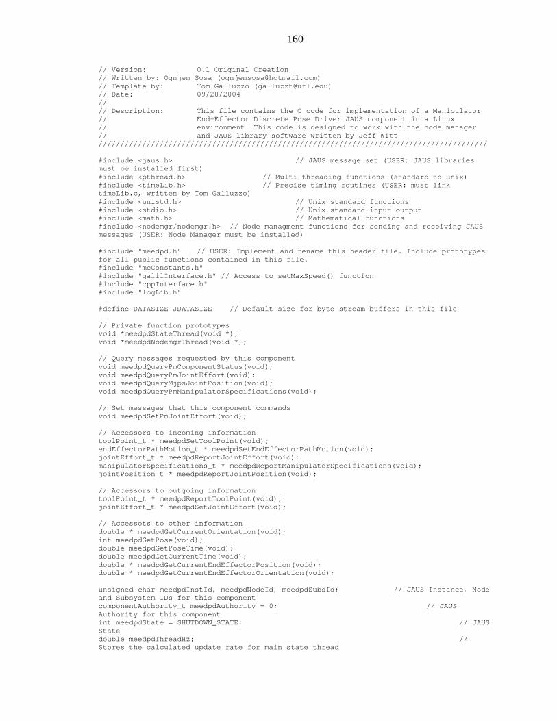
160
// Version: 0.1 Original Creation // Written by: Ognjen Sosa ([email protected]) // Template by: Tom Galluzzo ([email protected]) // Date: 09/28/2004 // // Description: This file contains the C code for implementation of a Manipulator // End-Effector Discrete Pose Driver JAUS component in a Linux // environment. This code is designed to work with the node manager // and JAUS library software written by Jeff Witt ///////////////////////////////////////////////////////////////////////////////////////// #include <jaus.h> // JAUS message set (USER: JAUS libraries must be installed first) #include <pthread.h> // Multi-threading functions (standard to unix) #include <timeLib.h> // Precise timing routines (USER: must link timeLib.c, written by Tom Galluzzo) #include <unistd.h> // Unix standard functions #include <stdio.h> // Unix standard input-output #include <math.h> // Mathematical functions #include <nodemgr/nodemgr.h> // Node managment functions for sending and receiving JAUS messages (USER: Node Manager must be installed) #include "meedpd.h" // USER: Implement and rename this header file. Include prototypes for all public functions contained in this file. #include "mcConstants.h" #include "galilInterface.h" // Access to setMaxSpeed() function #include "cppInterface.h" #include "logLib.h" #define DATASIZE JDATASIZE // Default size for byte stream buffers in this file // Private function prototypes void *meedpdStateThread(void *); void *meedpdNodemgrThread(void *); // Query messages requested by this component void meedpdQueryPmComponentStatus(void); void meedpdQueryPmJointEffort(void); void meedpdQueryMjpsJointPosition(void); void meedpdQueryPmManipulatorSpecifications(void); // Set messages that this component commands void meedpdSetPmJointEffort(void); // Accessors to incoming information toolPoint_t * meedpdSetToolPoint(void); endEffectorPathMotion_t * meedpdSetEndEffectorPathMotion(void); jointEffort_t * meedpdReportJointEffort(void); manipulatorSpecifications_t * meedpdReportManipulatorSpecifications(void); jointPosition_t * meedpdReportJointPosition(void); // Accessors to outgoing information toolPoint_t * meedpdReportToolPoint(void); jointEffort_t * meedpdSetJointEffort(void); // Accessots to other information double * meedpdGetCurrentOrientation(void); int meedpdGetPose(void); double meedpdGetPoseTime(void); double meedpdGetCurrentTime(void); double * meedpdGetCurrentEndEffectorPosition(void); double * meedpdGetCurrentEndEffectorOrientation(void); unsigned char meedpdInstId, meedpdNodeId, meedpdSubsId; // JAUS Instance, Node and Subsystem IDs for this component componentAuthority_t meedpdAuthority = 0; // JAUS Authority for this component int meedpdState = SHUTDOWN_STATE; // JAUS State double meedpdThreadHz; // Stores the calculated update rate for main state thread

161
unsigned char meedpdCtrlCmptInstId, meedpdCtrlCmptCompId; // Stores identity of the component currently in control unsigned char meedpdCtrlCmptNodeId, meedpdCtrlCmptSubsId; // Stores identity of the component currently in control unsigned char meedpdCtrlCmptAuthority; // Stores the authority level of the component currently in control int meedpdUnderControl = FALSE; // FALSE - not under control, TRUE is under control int meedpdRun = FALSE; int meedpdStateThreadRunning = FALSE; pthread_t meedpdStateThreadId; // pthread node manager thread identifier int meedpdNodemgrThreadRunning = FALSE; pthread_t meedpdNodemgrThreadId; // pthread node manager thread identifier // Structure storing incoming request under case SET TOOL POINT static toolPoint_t setToolPoint_6; // Structure storing incoming request under case SET END EFFECTOR DISCRETE_POSE static endEffectorPathMotion_t setEndEffectorPathMotion; // Structure storing incoming request under case QUERY_TOOL_POINT static toolPoint_t reportedToolPoint; // Structures storing queried information static jointEffort_t reportedJointEffort; static manipulatorSpecifications_t reportedManipulatorSpecifications; static jointPosition_t reportedJointPosition; // Structure storing outgoing request to the PRIMITIVE MANIPULATOR static jointEffort_t setJointEffort; static double max_speed[NUM_JOINTS], max_acceleration[NUM_JOINTS], max_deceleration[NUM_JOINTS]; static double cmd_position[NUM_JOINTS]; static int num_soln; static double orientS[3], orientA[3]; static double des_position[3], des_orientS[3], des_orientA[3], curr_orientation[4], cmd_orientation[4]; static int pose, numPoses; static double ref_time = 0, rel_time = 0, init_pose_time = 0, pose_time = 0; jmh_t meedpdScHeader; jms_t meedpdJms; // An accessor to the Node Manager JAUS Message Service (Jms) for this component int meedpdScActive = FALSE; int meedpdPmState = -1; unsigned char meedpdPmNodeId = 0; int meedpdPmControl = FALSE; // Function: meedpdStartup // Access: Public // Description: This function allows the abstracted component functionality contained in this file to be started from an external source. // It must be called first before the component state machine and node manager interaction will begin // Each call to "meedpdStartup" should be followed by one call to the "cmptShutdown" function int meedpdStartup(void) { pthread_attr_t attr; // Thread attributed for the component threads spawned in this function ref_time = getTimeSeconds(); if(meedpdState == SHUTDOWN_STATE) // Execute the startup routines only if the component is not running {

162
// Check in to the Node Manager and obtain Instance, Node and Subsystem IDs if(jcmCheckIn(MANIPULATOR_END_EFFECTOR_DISCRETE_POSE_DRIVER, &meedpdInstId, &meedpdNodeId, &meedpdSubsId) < 0) // USER: Insert your component ID define on this line { cError("meedpd: Could not check in to nodemgr\n"); return MEEDPD_NODE_MANAGER_CHECKIN_ERROR; } // Open a conection to the Node Manager and obtain a Jms accessor if((meedpdJms = jmsOpen(MANIPULATOR_END_EFFECTOR_DISCRETE_POSE_DRIVER, meedpdInstId, 0)) == NULL) // USER: Insert your component ID define on this line { cError("meedpd: Could not open connection to nodemgr\n"); jcmCheckOut(MANIPULATOR_END_EFFECTOR_DISCRETE_POSE_DRIVER, meedpdInstId); // USER: Insert your component ID define on this line return MEEDPD_JMS_OPEN_ERROR; } meedpdJms->timeout.tv_usec = 100000; // Timeout for non-blocking jmsRecv, specified in micro seconds pthread_attr_init(&attr); pthread_attr_setdetachstate(&attr, PTHREAD_CREATE_DETACHED); meedpdState = INITIALIZE_STATE; // Set the state of the JAUS state machine to INITIALIZE meedpdRun = TRUE; if(pthread_create(&meedpdStateThreadId, &attr, meedpdStateThread, NULL) != 0) { cError("meedpd: Could not create meedpdStateThread\n"); meedpdShutdown(); return MEEDPD_STATE_THREAD_CREATE_ERROR; } if(pthread_create(&meedpdNodemgrThreadId, &attr, meedpdNodemgrThread, NULL) != 0) { cError("meedpd: Could not create meedpdNodemgrThread\n"); meedpdShutdown(); return MEEDPD_NODEMGR_THREAD_CREATE_ERROR; } pthread_attr_destroy(&attr); } else { cError("meedpd: Attempted startup while not shutdown\n"); return MEEDPD_STARTUP_BEFORE_SHUTDOWN_ERROR; } return 0; } // Function: meedpdShutdown // Access: Public // Description: This function allows the abstracted component functionality contained in this file to be stoped from an external source. // If the component is in the running state, this function will terminate all threads running in this file // This function will also close the Jms connection to the Node Manager and check out the component from the Node Manager int meedpdShutdown(void) { double timeOutSec; if(meedpdState != SHUTDOWN_STATE) // Execute the startup routines only if the component is not running
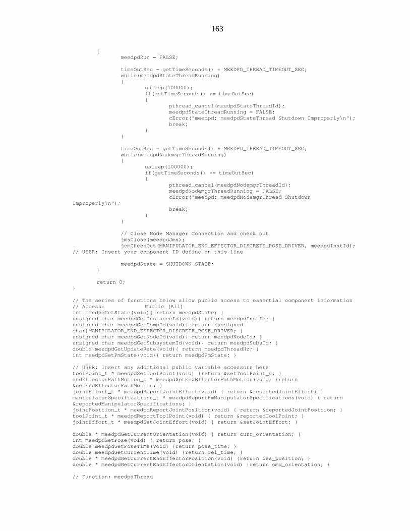
163
{ meedpdRun = FALSE; timeOutSec = getTimeSeconds() + MEEDPD_THREAD_TIMEOUT_SEC; while(meedpdStateThreadRunning) { usleep(100000); if(getTimeSeconds() >= timeOutSec) { pthread_cancel(meedpdStateThreadId); meedpdStateThreadRunning = FALSE; cError("meedpd: meedpdStateThread Shutdown Improperly\n"); break; } } timeOutSec = getTimeSeconds() + MEEDPD_THREAD_TIMEOUT_SEC; while(meedpdNodemgrThreadRunning) { usleep(100000); if(getTimeSeconds() >= timeOutSec) { pthread_cancel(meedpdNodemgrThreadId); meedpdNodemgrThreadRunning = FALSE; cError("meedpd: meedpdNodemgrThread Shutdown Improperly\n"); break; } } // Close Node Manager Connection and check out jmsClose(meedpdJms); jcmCheckOut(MANIPULATOR_END_EFFECTOR_DISCRETE_POSE_DRIVER, meedpdInstId); // USER: Insert your component ID define on this line meedpdState = SHUTDOWN_STATE; } return 0; } // The series of functions below allow public access to essential component information // Access: Public (All) int meedpdGetState(void){ return meedpdState; } unsigned char meedpdGetInstanceId(void){ return meedpdInstId; } unsigned char meedpdGetCompId(void){ return (unsigned char)MANIPULATOR_END_EFFECTOR_DISCRETE_POSE_DRIVER; } unsigned char meedpdGetNodeId(void){ return meedpdNodeId; } unsigned char meedpdGetSubsystemId(void){ return meedpdSubsId; } double meedpdGetUpdateRate(void){ return meedpdThreadHz; } int meedpdGetPmState(void){ return meedpdPmState; } // USER: Insert any additional public variable accessors here toolPoint_t * meedpdSetToolPoint(void) {return &setToolPoint_6; } endEffectorPathMotion_t * meedpdSetEndEffectorPathMotion(void) {return &setEndEffectorPathMotion; } jointEffort_t * meedpdReportJointEffort(void) { return &reportedJointEffort; } manipulatorSpecifications_t * meedpdReportPmManipulatorSpecifications(void) { return &reportedManipulatorSpecifications; } jointPosition_t * meedpdReportJointPosition(void) { return &reportedJointPosition; } toolPoint_t * meedpdReportToolPoint(void) { return &reportedToolPoint; } jointEffort_t * meedpdSetJointEffort(void) { return &setJointEffort; } double * meedpdGetCurrentOrientation(void) { return curr_orientation; } int meedpdGetPose(void) { return pose; } double meedpdGetPoseTime(void) {return pose_time; } double meedpdGetCurrentTime(void) {return rel_time; } double * meedpdGetCurrentEndEffectorPosition(void) {return des_position; } double * meedpdGetCurrentEndEffectorOrientation(void) {return cmd_orientation; } // Function: meedpdThread

164
// Access: Private // Description: All core component functionality is contained in this thread. // All of the JAUS component state machine code can be found here. void *meedpdStateThread(void *threadData) { jmh_t txMsgHeader; double time, prevTime; unsigned char data[DATASIZE]; int i, j; double curr_position[NUM_JOINTS], curr_effort[NUM_JOINTS], cmd_effort[NUM_JOINTS], curr_tool_point[3], tool_point_6[3], cmd_position[3]; double spec_a[NUM_JOINTS-1], spec_alpha[NUM_JOINTS-1], spec_S[NUM_JOINTS]; meedpdStateThreadRunning = TRUE; // // Setup transmit header txMsgHeader.isExpMsg = 0; // not experimental msg - USER: change to 1 if experimental txMsgHeader.isSvcMsg = 0; // not a service connection txMsgHeader.acknCtrl = 0; // no ack/nak txMsgHeader.priority = 6; // default priority txMsgHeader.reserved = 0; txMsgHeader.version = 1; // JAUS 3.0u txMsgHeader.srcInstId = meedpdInstId; txMsgHeader.srcCompId = MANIPULATOR_END_EFFECTOR_DISCRETE_POSE_DRIVER; txMsgHeader.srcNodeId = meedpdNodeId; txMsgHeader.srcSubsId = meedpdSubsId; txMsgHeader.dataCtrl = 0; txMsgHeader.seqNumber = 0; time = getTimeSeconds(); meedpdState = INITIALIZE_STATE; // Set JAUS state to INITIALIZE while(meedpdRun) // Execute state machine code while not in the SHUTDOWN state { prevTime = time; time = getTimeSeconds(); meedpdThreadHz = 1.0/(time-prevTime); // Compute the update rate of this thread switch(meedpdState) // Switch component behavior based on which state the machine is in { case INITIALIZE_STATE: //Check the status of PRIMITIVE MANIPULATOR meedpdQueryPmComponentStatus(); if(meedpdPmState == EMERGENCY_STATE) { cError("meedpd: PM in emergency state, switching to emergency state"); meedpdState = EMERGENCY_STATE; } if(meedpdPmState == STANDBY_STATE) { txMsgHeader.cmdCode = RESUME; txMsgHeader.dstInstId = 1; txMsgHeader.dstCompId = PRIMITIVE_MANIPULATOR; txMsgHeader.dstNodeId = meedpdNodeId; txMsgHeader.dstSubsId = meedpdSubsId ; txMsgHeader.dataBytes = 0; jmsSend(meedpdJms, &txMsgHeader, data, txMsgHeader.dataBytes); } if(meedpdPmState == READY_STATE) meedpdState = STANDBY_STATE; break; case STANDBY_STATE: ref_time = getTimeSeconds(); rel_time = getTimeSeconds() - ref_time; pose = 0, j = 0;

165
break; case READY_STATE: // Set up default velocity, acceleration, and deceleration values for (i=0; i<NUM_JOINTS; i++) { if (i == 0){ max_speed[i] = 5000 / J1_RAD_TO_ENC;//reportedManipulatorSpecifications.jointSpecifications[i].jointMaximumVelocity / 1000; max_acceleration[i] = 128000 / J1_RAD_TO_ENC; } else if (i == 1) { max_speed[i] = 5000 / J2_RAD_TO_ENC; max_acceleration[i] = 128000 / J2_RAD_TO_ENC; } else if (i == 2) { max_speed[i] = 5000 / J3_RAD_TO_ENC; max_acceleration[i] = 128000 / J3_RAD_TO_ENC; } else if (i == 3) { max_speed[i] = 1000 / J4_RAD_TO_ENC; max_acceleration[i] = 128000 / J4_RAD_TO_ENC; } else if (i == 4) { max_speed[i] = 1000 / J5_RAD_TO_ENC; max_acceleration[i] = 128000 / J5_RAD_TO_ENC; } else { max_speed[i] = 1000 / J6_RAD_TO_ENC;//reportedManipulatorSpecifications.jointNmaximumVelocity / 1000; max_acceleration[i] = 128000 / J6_RAD_TO_ENC; } max_deceleration[i] = max_acceleration[i]; } setMaxSpeed(max_speed); setMaxAcceleration(max_acceleration); setMaxDeceleration(max_deceleration); //Check the status of PRIMITIVE MANIPULATOR meedpdQueryPmComponentStatus(); if(meedpdPmState == EMERGENCY_STATE) { cError("meedpd: PM in emergency state, switching to emergency state"); meedpdState = EMERGENCY_STATE; } numPoses = setEndEffectorPathMotion.numPoses; // Start timer rel_time = getTimeSeconds() - ref_time; init_pose_time = setEndEffectorPathMotion.endEffectorPoses[0].time; pose_time = setEndEffectorPathMotion.endEffectorPoses[j].time; // Set zero efforts until first motion profle comes in if (rel_time <= init_pose_time) { pose = 0; // Set Joint Efforts to zero setJointEffort.numJoints = NUM_JOINTS;

166
for (i=0; i<NUM_JOINTS; i++) { setJointEffort.jointEffort[i] = 0; } meedpdSetPmJointEffort(); } // Query for required information meedpdQueryMjpsJointPosition(); meedpdQueryPmManipulatorSpecifications(); meedpdQueryPmJointEffort(); for (i=0; i<NUM_JOINTS; i++) { curr_position[i] = reportedJointPosition.jointPosition[i]; curr_effort[i] = reportedJointEffort.jointEffort[i]; } for(i=0; i<NUM_JOINTS-1; i++) { spec_a[i] = reportedManipulatorSpecifications.jointSpecifications[i].linkLength; spec_alpha[i] = reportedManipulatorSpecifications.jointSpecifications[i].twistAngle/1000; if (i<3 || i==4) spec_S[i] = reportedManipulatorSpecifications.jointSpecifications[i].jointOffsetOrAngle; else if (i==3) spec_S[i] = -(reportedManipulatorSpecifications.jointSpecifications[i].jointOffsetOrAngle); } spec_S[5] = -(reportedManipulatorSpecifications.jointNoffsetOrAngle); // Extract incoming tool point in 6th coordinate tool_point_6[0] = 0; // mm tool_point_6[1] = 10; tool_point_6[2] = 0; // This function returns the current position and orientation of the end-effector getCurrentEndEffectorPose(spec_a, spec_alpha, spec_S, tool_point_6, curr_position, curr_tool_point, orientS, orientA); PmatrixToQuaternion(orientA, orientS, curr_orientation); // Report Tool Point reportedToolPoint.X = curr_tool_point[0]; reportedToolPoint.Y = curr_tool_point[1]; reportedToolPoint.Z = curr_tool_point[2]; if (rel_time >= pose_time) { // Extract information about desired position and orientation des_position[0] = setEndEffectorPathMotion.endEffectorPoses[j].X * 1000; // mm des_position[1] = setEndEffectorPathMotion.endEffectorPoses[j].Y * 1000; des_position[2] = setEndEffectorPathMotion.endEffectorPoses[j].Z * 1000; cmd_orientation[0] = setEndEffectorPathMotion.endEffectorPoses[j].quaternionQcomponentD; cmd_orientation[1] = setEndEffectorPathMotion.endEffectorPoses[j].quaternionQcomponentA; cmd_orientation[2] = setEndEffectorPathMotion.endEffectorPoses[j].quaternionQcomponentB;

167
cmd_orientation[3] = setEndEffectorPathMotion.endEffectorPoses[j].quaternionQcomponentC; PquaternionToMatrix(cmd_orientation, des_orientS, des_orientA); // This function returns the joint angles corresponding to the desired pose getDesiredJointAngles(des_position, des_orientS, des_orientA, cmd_position); if (j < numPoses-1){ pose++; j++; } else { j = numPoses-1; pose = numPoses; } } // This function performs closed loop end effector pose control endEffectorDiscretePoseDriver(cmd_position, curr_position, cmd_effort); // Set Joint Efforts setJointEffort.numJoints = NUM_JOINTS; for (i=0; i<NUM_JOINTS; i++) { setJointEffort.jointEffort[i] = cmd_effort[i]; } meedpdSetPmJointEffort(); break; case EMERGENCY_STATE: break; case FAILURE_STATE: break; case SHUTDOWN_STATE: break; default: meedpdState = FAILURE_STATE; // The default case is undefined, therefore go into Failure State break; } usleep(1000); // Sleep for one millisecond } // Sleep for 50 milliseconds and then exit usleep(50000); meedpdStateThreadRunning = FALSE; pthread_exit(NULL); } // Function: meedpdNodemgrThread // Access: Private // Description: This thread is responsible for handling incoming JAUS messages from the Node Manager JAUS message service (Jms) // incoming messages are processed according to message type. void *meedpdNodemgrThread(void *threadData) { jmh_t rxMsgHeader, txMsgHeader; // Declare JAUS header data structures, where the jmh_t data structure is defined in jaus.h unsigned char data[DATASIZE]; createServiceConnection_t createServiceConnection;

168
confirmServiceConnection_t confirmServiceConnection; activateServiceConnection_t activateServiceConnection; suspendServiceConnection_t suspendServiceConnection; terminateServiceConnection_t terminateServiceConnection; requestComponentControl_t requestComponentControl; confirmComponentControl_t confirmComponentControl; componentAuthority_t componentAuthority; componentStatus_t componentStatus; int recvCount; meedpdNodemgrThreadRunning = TRUE; // // Setup transmit header txMsgHeader.isExpMsg = 0; // not experimental msg - USER: change to 1 if experimental txMsgHeader.isSvcMsg = 0; // not a service connection txMsgHeader.acknCtrl = 0; // no ack/nak txMsgHeader.priority = 6; // default priority txMsgHeader.reserved = 0; txMsgHeader.version = 1; // JAUS 3.0 txMsgHeader.srcInstId = meedpdInstId; txMsgHeader.srcCompId = MANIPULATOR_END_EFFECTOR_DISCRETE_POSE_DRIVER; txMsgHeader.srcNodeId = meedpdNodeId; txMsgHeader.srcSubsId = meedpdSubsId; txMsgHeader.dataCtrl = 0; txMsgHeader.seqNumber = 0; while(meedpdRun) // Execute incoming JAUS message processing while not in the SHUTDOWN state { // Check for a new message in the Node Manager JMS queue // If a message is present then store the header information in rxMsgHeader, and store the message content information in the data buffer recvCount = jmsRecv(meedpdJms, &rxMsgHeader, data, DATASIZE); if(recvCount < 0) { cError("meedpd: Node manager jmsRecv returned error: %d\n", recvCount); break; } if(recvCount == 0) continue; // This block of code is intended to reject commands from non-controlling components // However, the one exception allowed is a REQUEST_COMPONENT_CONTROL if(meedpdUnderControl && rxMsgHeader.cmdCode < 0x2000) // If not currently under control or it's not a command, then go to the switch statement { // If the source component isn't the one in control, and it's not a request to gain control, then exit this iteration of the while loop if( !( meedpdCtrlCmptInstId==rxMsgHeader.srcInstId && meedpdCtrlCmptCompId==rxMsgHeader.srcCompId && meedpdCtrlCmptNodeId==rxMsgHeader.srcNodeId && meedpdCtrlCmptSubsId==rxMsgHeader.srcSubsId)&& !( rxMsgHeader.cmdCode==REQUEST_COMPONENT_CONTROL) )continue; // to next iteration } switch(rxMsgHeader.cmdCode) // Switch the processing algorithm according to the JAUS message type { // Set the component authority according to the incoming authority code case SET_COMPONENT_AUTHORITY: convertComponentAuthority(data, &meedpdAuthority, DATASIZE, UNPACK); // Unpack and store the incoming authority code break; case SHUTDOWN: meedpdState = SHUTDOWN_STATE; break;

169
case STANDBY: if(meedpdState == READY_STATE) meedpdState = STANDBY_STATE; break; case RESUME: if(meedpdState == STANDBY_STATE) meedpdState = READY_STATE; break; case RESET: meedpdState = INITIALIZE_STATE; break; case SET_EMERGENCY: meedpdState = EMERGENCY_STATE; break; case CLEAR_EMERGENCY: meedpdState = STANDBY_STATE; break; case CREATE_SERVICE_CONNECTION: convertCreateServiceConnection(data, &createServiceConnection, DATASIZE, UNPACK); if(createServiceConnection.cmdCode == REPORT_JOINT_VELOCITY) { meedpdScHeader = txMsgHeader; meedpdScHeader.isSvcMsg = 1; meedpdScHeader.dstInstId = rxMsgHeader.srcInstId; meedpdScHeader.dstCompId = rxMsgHeader.srcCompId; meedpdScHeader.dstNodeId = rxMsgHeader.srcNodeId; meedpdScHeader.dstSubsId = rxMsgHeader.srcSubsId; meedpdScHeader.cmdCode = REPORT_JOINT_VELOCITY; meedpdScHeader.seqNumber = 1; confirmServiceConnection.cmdCode = REPORT_JOINT_VELOCITY; confirmServiceConnection.instanceId = 1; confirmServiceConnection.confirmedRate = createServiceConnection.requestedRate; // BUG: The actual rate may not be the same as the request confirmServiceConnection.responseCode = CONNECTION_SUCCESSFUL; txMsgHeader.cmdCode = CONFIRM_SERVICE_CONNECTION; txMsgHeader.dstSubsId = rxMsgHeader.srcSubsId; txMsgHeader.dstNodeId = rxMsgHeader.srcNodeId; txMsgHeader.dstCompId = rxMsgHeader.srcCompId; txMsgHeader.dstInstId = rxMsgHeader.srcInstId; txMsgHeader.dataBytes = convertConfirmServiceConnection(data, &confirmServiceConnection, DATASIZE, PACK); jmsSend(meedpdJms, &txMsgHeader, data, txMsgHeader.dataBytes); meedpdScActive = TRUE; } else { confirmServiceConnection.cmdCode = createServiceConnection.cmdCode; confirmServiceConnection.instanceId = 1; confirmServiceConnection.confirmedRate = createServiceConnection.requestedRate; confirmServiceConnection.responseCode = CONNECTION_REFUSED; txMsgHeader.cmdCode = CONFIRM_SERVICE_CONNECTION; txMsgHeader.dstSubsId = rxMsgHeader.srcSubsId; txMsgHeader.dstNodeId = rxMsgHeader.srcNodeId; txMsgHeader.dstCompId = rxMsgHeader.srcCompId;

170
txMsgHeader.dstInstId = rxMsgHeader.srcInstId; txMsgHeader.dataBytes = convertConfirmServiceConnection(data, &confirmServiceConnection, DATASIZE, PACK); jmsSend(meedpdJms, &txMsgHeader, data, txMsgHeader.dataBytes); } break; case CONFIRM_SERVICE_CONNECTION: convertConfirmServiceConnection(data, &confirmServiceConnection, DATASIZE, UNPACK); // USER: Insert code here to handle the confirm service connection message break; case ACTIVATE_SERVICE_CONNECTION: convertActivateServiceConnection(data, &activateServiceConnection, DATASIZE, UNPACK); // USER: Insert code here to handle the activate service connection message break; case SUSPEND_SERVICE_CONNECTION: convertSuspendServiceConnection(data, &suspendServiceConnection, DATASIZE, UNPACK); // USER: Insert code here to handle the suspend service connection message break; case TERMINATE_SERVICE_CONNECTION: convertTerminateServiceConnection(data, &terminateServiceConnection, DATASIZE, UNPACK); if (terminateServiceConnection.cmdCode == REPORT_JOINT_VELOCITY) meedpdScActive = FALSE; break; case REQUEST_COMPONENT_CONTROL: convertRequestComponentControl(data, &requestComponentControl, DATASIZE, UNPACK); if(meedpdUnderControl) { if(requestComponentControl > meedpdCtrlCmptAuthority) // Test for higher authority { // Terminate control of current component txMsgHeader.cmdCode = REJECT_COMPONENT_CONTROL; txMsgHeader.dstSubsId = meedpdCtrlCmptSubsId; txMsgHeader.dstNodeId = meedpdCtrlCmptNodeId; txMsgHeader.dstCompId = meedpdCtrlCmptCompId; txMsgHeader.dstInstId = meedpdCtrlCmptInstId; txMsgHeader.dataBytes = 0; jmsSend(meedpdJms, &txMsgHeader, data, txMsgHeader.dataBytes); // Accept control of new component txMsgHeader.cmdCode = CONFIRM_COMPONENT_CONTROL; txMsgHeader.dstSubsId = rxMsgHeader.srcSubsId; txMsgHeader.dstNodeId = rxMsgHeader.srcNodeId; txMsgHeader.dstCompId = rxMsgHeader.srcCompId;

171
txMsgHeader.dstInstId = rxMsgHeader.srcInstId; confirmComponentControl.asByte = 0; txMsgHeader.dataBytes = convertConfirmComponentControl(data, &confirmComponentControl, DATASIZE, PACK); jmsSend(meedpdJms, &txMsgHeader, data, txMsgHeader.dataBytes); meedpdCtrlCmptInstId = rxMsgHeader.srcInstId; meedpdCtrlCmptCompId = rxMsgHeader.srcCompId; meedpdCtrlCmptNodeId = rxMsgHeader.srcNodeId; meedpdCtrlCmptSubsId = rxMsgHeader.srcSubsId; meedpdCtrlCmptAuthority = requestComponentControl; } else { if( rxMsgHeader.srcSubsId != meedpdCtrlCmptSubsId || rxMsgHeader.srcNodeId != meedpdCtrlCmptNodeId || rxMsgHeader.srcCompId != meedpdCtrlCmptCompId || rxMsgHeader.srcInstId != meedpdCtrlCmptInstId ) { txMsgHeader.cmdCode = REJECT_COMPONENT_CONTROL; txMsgHeader.dstSubsId = rxMsgHeader.srcSubsId; txMsgHeader.dstNodeId = rxMsgHeader.srcNodeId; txMsgHeader.dstCompId = rxMsgHeader.srcCompId; txMsgHeader.dstInstId = rxMsgHeader.srcInstId; txMsgHeader.dataBytes = 0; jmsSend(meedpdJms, &txMsgHeader, data, txMsgHeader.dataBytes); } } } else // Not currently under component control, so give control { txMsgHeader.cmdCode = CONFIRM_COMPONENT_CONTROL; txMsgHeader.dstSubsId = rxMsgHeader.srcSubsId; txMsgHeader.dstNodeId = rxMsgHeader.srcNodeId; txMsgHeader.dstCompId = rxMsgHeader.srcCompId; txMsgHeader.dstInstId = rxMsgHeader.srcInstId; confirmComponentControl.asByte = 0; txMsgHeader.dataBytes = convertConfirmComponentControl(data, &confirmComponentControl, DATASIZE, PACK); jmsSend(meedpdJms, &txMsgHeader, data, txMsgHeader.dataBytes); meedpdCtrlCmptInstId = rxMsgHeader.srcInstId; meedpdCtrlCmptCompId = rxMsgHeader.srcCompId; meedpdCtrlCmptNodeId = rxMsgHeader.srcNodeId; meedpdCtrlCmptSubsId = rxMsgHeader.srcSubsId; meedpdCtrlCmptAuthority = requestComponentControl; meedpdUnderControl = TRUE; } break; case RELEASE_COMPONENT_CONTROL: meedpdUnderControl = FALSE; break; case CONFIRM_COMPONENT_CONTROL: convertConfirmComponentControl(data, &confirmComponentControl, DATASIZE, UNPACK);

172
// USER: Insert code here to handle the confirm component control message if needed break; case REJECT_COMPONENT_CONTROL: // USER: Insert code here to handle the reject component control message if needed break; case QUERY_COMPONENT_AUTHORITY: txMsgHeader.cmdCode = REPORT_COMPONENT_AUTHORITY; txMsgHeader.dstSubsId = rxMsgHeader.srcSubsId; txMsgHeader.dstNodeId = rxMsgHeader.srcNodeId; txMsgHeader.dstCompId = rxMsgHeader.srcCompId; txMsgHeader.dstInstId = rxMsgHeader.srcInstId; componentAuthority = meedpdAuthority; txMsgHeader.dataBytes = convertComponentAuthority(data, &componentAuthority, DATASIZE, PACK); jmsSend(meedpdJms, &txMsgHeader, data, txMsgHeader.dataBytes); break; case QUERY_COMPONENT_STATUS: txMsgHeader.cmdCode = REPORT_COMPONENT_STATUS; txMsgHeader.dstSubsId = rxMsgHeader.srcSubsId; txMsgHeader.dstNodeId = rxMsgHeader.srcNodeId; txMsgHeader.dstCompId = rxMsgHeader.srcCompId; txMsgHeader.dstInstId = rxMsgHeader.srcInstId; componentStatus.primaryStatus.asByte = meedpdState; txMsgHeader.dataBytes = convertComponentStatus(data, &componentStatus, DATASIZE, PACK); jmsSend(meedpdJms, &txMsgHeader, data, txMsgHeader.dataBytes); break; case REPORT_COMPONENT_AUTHORITY: convertComponentAuthority(data, &componentAuthority, DATASIZE, UNPACK); // USER: Insert code here to handle the report component authority message if needed break; case REPORT_COMPONENT_STATUS: convertComponentStatus(data, &componentStatus, DATASIZE, UNPACK); if(rxMsgHeader.srcCompId == PRIMITIVE_MANIPULATOR) meedpdPmState = componentStatus.primaryStatus.asField.primaryStatusCode; break; case SET_END_EFFECTOR_PATH_MOTION: convertEndEffectorPathMotion(data, &setEndEffectorPathMotion, DATASIZE, UNPACK); break; case REPORT_JOINT_EFFORT: convertJointEffort(data, &reportedJointEffort, DATASIZE, UNPACK); break; case REPORT_MANIPULATOR_SPECIFICATIONS: convertManipulatorSpecifications(data, &reportedManipulatorSpecifications, DATASIZE, UNPACK); break; case REPORT_JOINT_POSITION: convertJointPosition(data, &reportedJointPosition, DATASIZE, UNPACK); break; case QUERY_TOOL_POINT:

173
txMsgHeader.cmdCode = REPORT_TOOL_POINT; txMsgHeader.dstInstId = rxMsgHeader.srcInstId; txMsgHeader.dstCompId = rxMsgHeader.srcCompId; txMsgHeader.dstNodeId = rxMsgHeader.srcNodeId; txMsgHeader.dstSubsId = rxMsgHeader.srcSubsId; txMsgHeader.dataBytes = convertToolPoint(data, &reportedToolPoint, DATASIZE, PACK); jmsSend(meedpdJms, &txMsgHeader, data, txMsgHeader.dataBytes); break; default: break; } } meedpdNodemgrThreadRunning = FALSE; pthread_exit(NULL); } //////////////////////////////////////////////////////////////////////////////////// // Function used to send a message to the primitive manipulator and query for // component status. Only the primitive manipulator component performs the initial // system checks. Thus it is essential that primitive manipulator is running and its // status is ready before any other components are started up. //////////////////////////////////////////////////////////////////////////////////// void meedpdQueryPmComponentStatus(void) { jmh_t txMsg; unsigned char data[DATASIZE]; double requestTimeOutSec = 0.1; static double lastRequestTimeSec = 0; // Setup Transmit msg txMsg.isExpMsg = 0; txMsg.priority = 6; txMsg.acknCtrl = 0; txMsg.isSvcMsg = 0; txMsg.version = 1; txMsg.reserved = 0; txMsg.srcInstId = meedpdInstId; txMsg.srcCompId = MANIPULATOR_END_EFFECTOR_DISCRETE_POSE_DRIVER; txMsg.srcNodeId = meedpdNodeId; txMsg.srcSubsId = meedpdSubsId; txMsg.dataCtrl = 0; txMsg.seqNumber = 0; txMsg.cmdCode = QUERY_COMPONENT_STATUS; txMsg.dstInstId = 1; txMsg.dstCompId = PRIMITIVE_MANIPULATOR; txMsg.dstNodeId = meedpdNodeId; txMsg.dstSubsId = meedpdSubsId ; txMsg.dataBytes = 0; if( (getTimeSeconds() - lastRequestTimeSec) >= requestTimeOutSec) { jmsSend(meedpdJms, &txMsg, data, txMsg.dataBytes); lastRequestTimeSec = getTimeSeconds(); } } //////////////////////////////////////////////////////////////////////////////////// // Function used to set up a message sent to manipulator joint position sensor // to obtain current joint position data. //////////////////////////////////////////////////////////////////////////////////// void meedpdQueryMjpsJointPosition(void) { jmh_t txMsg; unsigned char data[DATASIZE]; double requestTimeOutSec = 0.1; static double lastRequestTimeSec = 0;

174
// Setup Transmit msg txMsg.isExpMsg = 0; txMsg.priority = 6; txMsg.acknCtrl = 0; txMsg.isSvcMsg = 0; txMsg.version = 1; txMsg.reserved = 0; txMsg.srcSubsId = meedpdSubsId; txMsg.srcNodeId = meedpdNodeId; txMsg.srcCompId = MANIPULATOR_END_EFFECTOR_DISCRETE_POSE_DRIVER; txMsg.srcInstId = meedpdInstId; txMsg.dataCtrl = 0; txMsg.seqNumber = 0; txMsg.cmdCode = QUERY_JOINT_POSITION; txMsg.dstInstId = 1; txMsg.dstCompId = MANIPULATOR_JOINT_POSITION_SENSOR; txMsg.dstNodeId = meedpdNodeId; txMsg.dstSubsId = meedpdSubsId ; txMsg.dataBytes = 0; if( (getTimeSeconds() - lastRequestTimeSec) >= requestTimeOutSec) { jmsSend(meedpdJms, &txMsg, data, txMsg.dataBytes); lastRequestTimeSec = getTimeSeconds(); } } //////////////////////////////////////////////////////////////////////////////////// // Function used to set up a message sent to the primitive manipulator to obtain // current effort values. //////////////////////////////////////////////////////////////////////////////////// void meedpdQueryPmJointEffort(void) { jmh_t txMsg; unsigned char data[DATASIZE]; double requestTimeOutSec = 0.1; static double lastRequestTimeSec = 0; // Setup Transmit msg txMsg.isExpMsg = 0; txMsg.priority = 6; txMsg.acknCtrl = 0; txMsg.isSvcMsg = 0; txMsg.version = 1; txMsg.reserved = 0; txMsg.srcSubsId = meedpdSubsId; txMsg.srcNodeId = meedpdNodeId; txMsg.srcCompId = MANIPULATOR_END_EFFECTOR_DISCRETE_POSE_DRIVER; txMsg.srcInstId = meedpdInstId; txMsg.dataCtrl = 0; txMsg.seqNumber = 0; txMsg.cmdCode = QUERY_JOINT_EFFORT; txMsg.dstInstId = 1; txMsg.dstCompId = PRIMITIVE_MANIPULATOR; txMsg.dstNodeId = meedpdNodeId; txMsg.dstSubsId = meedpdSubsId ; txMsg.dataBytes = 0; if( (getTimeSeconds() - lastRequestTimeSec) >= requestTimeOutSec) { jmsSend(meedpdJms, &txMsg, data, txMsg.dataBytes); lastRequestTimeSec = getTimeSeconds(); } } //////////////////////////////////////////////////////////////////////////////////// // Function used to set up a message sent to the primitive manipulator to obtain // manipulator specifications. //////////////////////////////////////////////////////////////////////////////////// void meedpdQueryPmManipulatorSpecifications(void) {

175
jmh_t txMsg; unsigned char data[DATASIZE]; double requestTimeOutSec = 0.1; static double lastRequestTimeSec = 0; // Setup Transmit msg txMsg.isExpMsg = 0; txMsg.priority = 6; txMsg.acknCtrl = 0; txMsg.isSvcMsg = 0; txMsg.version = 1; txMsg.reserved = 0; txMsg.srcSubsId = meedpdSubsId; txMsg.srcNodeId = meedpdNodeId; txMsg.srcCompId = MANIPULATOR_END_EFFECTOR_DISCRETE_POSE_DRIVER; txMsg.srcInstId = meedpdInstId; txMsg.dataCtrl = 0; txMsg.seqNumber = 0; txMsg.cmdCode = QUERY_MANIPULATOR_SPECIFICATIONS; txMsg.dstInstId = 1; txMsg.dstCompId = PRIMITIVE_MANIPULATOR; txMsg.dstNodeId = meedpdNodeId; txMsg.dstSubsId = meedpdSubsId ; txMsg.dataBytes = 0; if( (getTimeSeconds() - lastRequestTimeSec) >= requestTimeOutSec) { jmsSend(meedpdJms, &txMsg, data, txMsg.dataBytes); lastRequestTimeSec = getTimeSeconds(); } } //////////////////////////////////////////////////////////////////////////////////// // Function used to set up a message sent to the primitive manipulator with new // joint effort values. //////////////////////////////////////////////////////////////////////////////////// void meedpdSetPmJointEffort(void) { jmh_t txMsg; double requestTimeOutSec = 0.1; static double lastRequestTimeSec = 0; unsigned char data[DATASIZE]; //Setup Transmit Message txMsg.isExpMsg = 0; txMsg.priority = 6; txMsg.acknCtrl = 0; txMsg.isSvcMsg = 0; txMsg.version = 1; txMsg.reserved = 0; txMsg.srcInstId = meedpdInstId; txMsg.srcCompId = MANIPULATOR_END_EFFECTOR_DISCRETE_POSE_DRIVER; txMsg.srcNodeId = meedpdNodeId; txMsg.srcSubsId = meedpdSubsId; txMsg.dataCtrl = 0; txMsg.seqNumber = 0; txMsg.cmdCode = SET_JOINT_EFFORT; txMsg.dstInstId = 1; txMsg.dstCompId = PRIMITIVE_MANIPULATOR; txMsg.dstNodeId = meedpdNodeId; txMsg.dstSubsId = meedpdSubsId; txMsg.dataBytes = convertJointEffort(data, &setJointEffort, DATASIZE, PACK); if( (getTimeSeconds() - lastRequestTimeSec) >= requestTimeOutSec) { jmsSend(meedpdJms, &txMsg, data, txMsg.dataBytes); lastRequestTimeSec = getTimeSeconds(); } } ////////////////////////////////////////////////////////////////////////////////////

176
// Function used to perform closed loop end-effector position control //////////////////////////////////////////////////////////////////////////////////// void endEffectorDiscretePoseDriver(double *cmd_position, double *curr_position, double *cmd_effort) { int i; double k[NUM_JOINTS]; for (i=0; i<NUM_JOINTS; i++) { if (i < 3) k[i] = 34; else if (i == 3) k[i] = 34; else if (i == 4) k[i] = 15; else k[i] = 14; if (i == 0) cmd_effort[i] = ((cmd_position[i] - curr_position[i]) * k[i]) * J1_RAD_TO_ENC * 100 / 112000; else if (i == 1) cmd_effort[i] = ((cmd_position[i] - curr_position[i]) * k[i]) * J2_RAD_TO_ENC * 100 / 112000; else if (i == 2) cmd_effort[i] = ((cmd_position[i] - curr_position[i]) * k[i]) * J3_RAD_TO_ENC * 100 / 112000; else if (i == 3) cmd_effort[i] = ((cmd_position[i] - curr_position[i]) * k[i]) * J4_RAD_TO_ENC * 100 / 35000; else if (i == 4) cmd_effort[i] = ((cmd_position[i] - curr_position[i]) * k[i]) * J5_RAD_TO_ENC * 100 / 16000; else cmd_effort[i] = ((cmd_position[i] - curr_position[i]) * k[i]) * J6_RAD_TO_ENC * 100 / 15500; } } void PmatrixToQuaternion(double *orientA, double *orientS, double *curr_orientation) { double T, S; double W, X, Y, Z; double M0, M1, M2; double M4, M5, M6; double M8, M9, M10; M0 = orientA[0]; M4 = orientA[1]; M8 = orientA[2]; M1 = orientS[1]*orientA[2] - orientS[2]*orientA[1]; M5 = orientS[2]*orientA[0] - orientS[0]*orientA[2]; M9 = orientS[0]*orientA[1] - orientS[1]*orientA[0]; M2 = orientS[0]; M6 = orientS[1]; M10 = orientS[2]; T = M0 + M5 + M10 + 1; S = 0.5/sqrt(T); W = 0.25/S; X = (M9 - M6)*S; Y = (M2 - M8)*S; Z = (M4 - M1)*S; curr_orientation[0] = W; curr_orientation[1] = X; curr_orientation[2] = Y; curr_orientation[3] = Z; }

177
void PquaternionToMatrix(double *cmd_orientation,double *des_orientS, double *des_orientA) { double W, X, Y, Z; double M0, M1, M2; double M4, M5, M6; double M8, M9, M10; W = cmd_orientation[0]; X = cmd_orientation[1]; Y = cmd_orientation[2]; Z = cmd_orientation[3]; M0 = 1 - 2*Y*Y - 2*Z*Z; M4 = 2*X*Y + 2*Z*W; M8 = 2*X*Z - 2*Y*W; M1 = 2*X*Y - 2*Z*W; M5 = 1 - 2*X*X - 2*Z*Z; M9 = 2*Y*Z + 2*X*W; M2 = 2*X*Z + 2*Y*W; M6 = 2*Y*Z - 2*X*W; M10 = 1 - 2*X*X - 2*Y*Y; des_orientA[0] = M0; des_orientA[1] = M4; des_orientA[2] = M8; des_orientS[0] = M2; des_orientS[1] = M6; des_orientS[2] = M10; } ///////////////////////////////////////////////////////////////////////////////////////// // File: meedpd.h // Version: 0.1 Original Creation // Written by: Ognjen Sosa ([email protected]) // Template by: Tom Galluzzo ([email protected]) // Date: 09/28/2004 // // Description: This file contains the skeleton C header file code for implementing // the meedpd.c file ///////////////////////////////////////////////////////////////////////////////////////// #ifndef MEEDPD_H #define MEEDPD_H #include "jaus.h" #ifndef FALSE #define FALSE 0 #endif #ifndef TRUE #define TRUE 1 #endif #define MEEDPD_NODE_MANAGER_CHECKIN_ERROR -1 #define MEEDPD_JMS_OPEN_ERROR -2 #define MEEDPD_STARTUP_BEFORE_SHUTDOWN_ERROR -3 #define MEEDPD_STATE_THREAD_CREATE_ERROR -4 #define MEEDPD_NODEMGR_THREAD_CREATE_ERROR -5 #define MEEDPD_THREAD_TIMEOUT_SEC 1.0 // Public int meedpdStartup(void); int meedpdShutdown(void); int meedpdGetState(void);

178
unsigned char meedpdGetInstanceId(void); unsigned char meedpdGetCompId(void); unsigned char meedpdGetNodeId(void); unsigned char meedpdGetSubsystemId(void); double meedpdGetUpdateRate(void); int meedpdGetPmState(void); // Query messages requested by this component void meedpdQueryPmComponentStatus(void); void meedpdQueryPmJointEffort(void); void meedpdQueryMjpsJointPosition(void); void meedpdQueryPmManipulatorSpecifications(void); // Set messages that this component commands void meedpdSetPmJointEffort(void); // Accessors to incoming information toolPoint_t * meedpdSetToolPoint(void); endEffectorPathMotion_t * meedpdSetEndEffectorPathMotion(void); jointEffort_t * meedpdReportJointEffort(void); manipulatorSpecifications_t * meedpdReportManipulatorSpecifications(void); jointPosition_t * meedpdReportJointPosition(void); // Accessors to outgoing information toolPoint_t * meedpdReportToolPoint(void); jointEffort_t * meedpdSetJointEffort(void); double * meedpdGetCurrentOrientation(void); int meedpdGetPose(void); double meedpdGetPoseTime(void); double meedpdGetCurrentTime(void); double * meedpdGetCurrentEndEffectorPosition(void); double * meedpdGetCurrentEndEffectorOrientation(void); void PmatrixToQuaternion(double *, double *, double *); void PquaternionToMatrix(double *, double *, double *); void endEffectorDiscretePoseDriver(double *, double *, double *); #endif // MEEDPD_H
B.6 The Mc.c File and the Corresponding Header Mc.h
///////////////////////////////////////////////////////////////////////////////////////// // File: mc.c // Version: 0.1 Original Creation // Written by: Ognjen Sosa ([email protected]) // Date: 09/28/2004 // // Description: This file contains node startup and shutdown functions. "Manipulator // Control" (mc) node is used to spawn all the neccessary threads. Due to // very low bandwith to the Galil controller, only one of the driver // components can be running at the time. ///////////////////////////////////////////////////////////////////////////////////////// #include <stdio.h> #include <time.h> #include <unistd.h> #include "mc.h" int roboWorksReady = 0; int mcStartup(void) { char choice; int i; // Check if RoboWorks software is being used do {
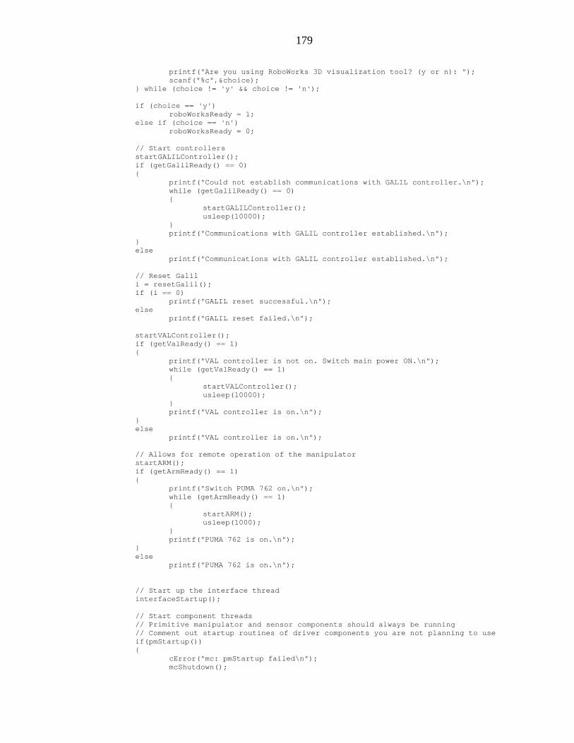
179
printf("Are you using RoboWorks 3D visualization tool? (y or n): "); scanf("%c",&choice); } while (choice != 'y' && choice != 'n'); if (choice == 'y') roboWorksReady = 1; else if (choice == 'n') roboWorksReady = 0; // Start controllers startGALILController(); if (getGalilReady() == 0) { printf("Could not establish communications with GALIL controller.\n"); while (getGalilReady() == 0) { startGALILController(); usleep(10000); } printf("Communications with GALIL controller established.\n"); } else printf("Communications with GALIL controller established.\n"); // Reset Galil i = resetGalil(); if (i == 0) printf("GALIL reset successful.\n"); else printf("GALIL reset failed.\n"); startVALController(); if (getValReady() == 1) { printf("VAL controller is not on. Switch main power ON.\n"); while (getValReady() == 1) { startVALController(); usleep(10000); } printf("VAL controller is on.\n"); } else printf("VAL controller is on.\n"); // Allows for remote operation of the manipulator startARM(); if (getArmReady() == 1) { printf("Switch PUMA 762 on.\n"); while (getArmReady() == 1) { startARM(); usleep(1000); } printf("PUMA 762 is on.\n"); } else printf("PUMA 762 is on.\n"); // Start up the interface thread interfaceStartup(); // Start component threads // Primitive manipulator and sensor components should always be running // Comment out startup routines of driver components you are not planning to use if(pmStartup()) { cError("mc: pmStartup failed\n"); mcShutdown();

180
return MC_PM_STARTUP_FAILED; } if (mjpsStartup()) { cError("mc: mjpsStartup failed\n"); mjpsShutdown(); return MC_MJPS_STARTUP_FAILED; } if (mjvsStartup()) { cError("mc: mjvsStartup failed\n"); mjvsShutdown(); return MC_MJVS_STARTUP_FAILED; } if (mjftsStartup()) { cError("mc: mjftsStartup failed\n"); mjftsShutdown(); return MC_MJFTS_STARTUP_FAILED; } if (mjpdStartup()) { cError("mc: mjpdStartup failed\n"); mjpdShutdown(); return MC_MJPD_STARTUP_FAILED; } if (mjvdStartup()) { cError("mc: mjvdStartup failed\n"); mjvdShutdown(); return MC_MJVD_STARTUP_FAILED; } if (mjmdStartup()) { cError("mc: mjmdStartup failed\n"); mjmdShutdown(); return MC_MJMD_STARTUP_FAILED; } if (meepdStartup()) { cError("mc: meepdStartup failed\n"); meepdShutdown(); return MC_MEEPD_STARTUP_FAILED; } if (meedpdStartup()) { cError("mc: meedpdStartup failed\n"); meedpdShutdown(); return MC_MEEDPD_STARTUP_FAILED; } return 0; }

181
int mcShutdown(void) { pmShutdown(); mjpsShutdown(); mjvsShutdown(); mjftsShutdown(); mjpdShutdown(); mjvdShutdown(); mjmdShutdown(); meepdShutdown(); meedpdShutdown(); interfaceShutdown(); return 0; } int getRoboWorksReady(void) { return roboWorksReady; } const char *mcGetName(void) { static const char *mcName = MC_NAME_STRING; return mcName; } ///////////////////////////////////////////////////////////////////////////////////////// // File: mc.h // Version: 0.1 Original Creation // Written by: Ognjen Sosa ([email protected]) // Date: 09/28/2004 // // Description: This file contians function prototypes required for mc.c ///////////////////////////////////////////////////////////////////////////////////////// #ifndef NODE_H #define NODE_H #ifndef TRUE #define TRUE 1 #endif #ifndef FALSE #define FALSE 0 #endif #define MC_NAME_STRING "Manipulator Control" #define MC_PM_STARTUP_FAILED -1 #define MC_MJPS_STARTUP_FAILED -2 #define MC_MJVS_STARTUP_FAILED -3 #define MC_MJFTS_STARTUP_FAILED -4 #define MC_MJPD_STARTUP_FAILED -5 #define MC_MEEPD_STARTUP_FAILED -6 #define MC_MJVD_STARTUP_FAILED -7 #define MC_MJMD_STARTUP_FAILED -9 #define MC_MEEDPD_STARTUP_FAILED -10 int mcStartup(void); int mcShutdown(void); int getRoboWorksReady(void); const char *mcGetName(void); #include "pm.h" #include "mjps.h" #include "mjvs.h" #include "mjfts.h" #include "mjpd.h" #include "mjvd.h"
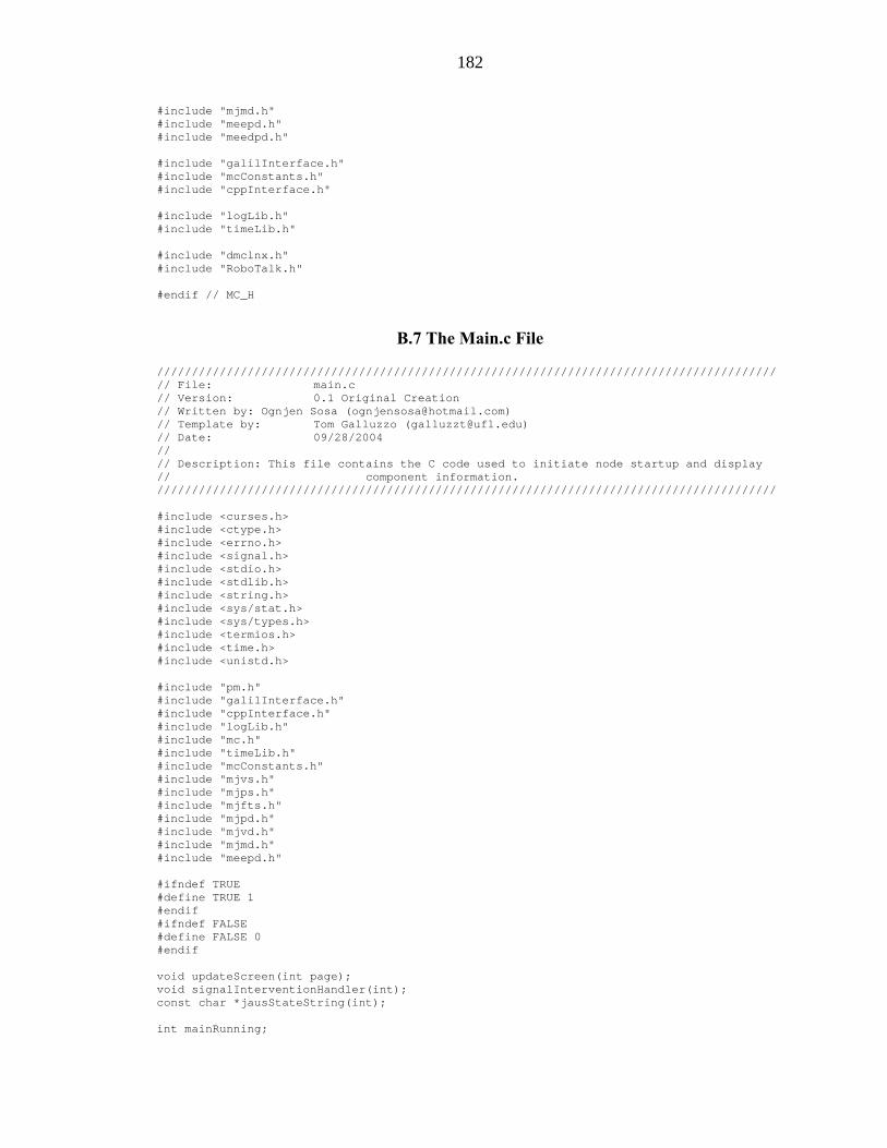
182
#include "mjmd.h" #include "meepd.h" #include "meedpd.h" #include "galilInterface.h" #include "mcConstants.h" #include "cppInterface.h" #include "logLib.h" #include "timeLib.h" #include "dmclnx.h" #include "RoboTalk.h" #endif // MC_H
B.7 The Main.c File
///////////////////////////////////////////////////////////////////////////////////////// // File: main.c // Version: 0.1 Original Creation // Written by: Ognjen Sosa ([email protected]) // Template by: Tom Galluzzo ([email protected]) // Date: 09/28/2004 // // Description: This file contains the C code used to initiate node startup and display // component information. ///////////////////////////////////////////////////////////////////////////////////////// #include <curses.h> #include <ctype.h> #include <errno.h> #include <signal.h> #include <stdio.h> #include <stdlib.h> #include <string.h> #include <sys/stat.h> #include <sys/types.h> #include <termios.h> #include <time.h> #include <unistd.h> #include "pm.h" #include "galilInterface.h" #include "cppInterface.h" #include "logLib.h" #include "mc.h" #include "timeLib.h" #include "mcConstants.h" #include "mjvs.h" #include "mjps.h" #include "mjfts.h" #include "mjpd.h" #include "mjvd.h" #include "mjmd.h" #include "meepd.h" #ifndef TRUE #define TRUE 1 #endif #ifndef FALSE #define FALSE 0 #endif void updateScreen(int page); void signalInterventionHandler(int); const char *jausStateString(int); int mainRunning;

183
int main(int argCount, char **argString) { int i; char choice=0; int verbose = FALSE; int debugLevel = 0; struct termios newTermios; struct termios stored; FILE *logFile = NULL; char logFileStr[128] = {0}; time_t timeStamp; char timeString[64]; int page = 0; //Get and Format Time String time(&timeStamp); strftime(timeString, 63, "%m-%d-%Y %X", localtime(&timeStamp)); system("clear"); printf("main: CIMAR Core Executable: %s\n", timeString); if(mkdir("/var/log/CIMAR/", 0777) < 0) { if(errno != EEXIST) { perror("main: Error"); return -1; } } for(i=1; i<argCount; i++) { if(argString[i][0] == '-') { switch(argString[i][1]) { case 'v': verbose = TRUE; setLogVerbose(TRUE); break; case 'd': if(argString[i][2] == '+') { setDebugLogic(DEBUG_GREATER_THAN); debugLevel = atoi(&argString[i][3]); } else if(argString[i][2] == '-') { setDebugLogic(DEBUG_LESS_THAN); debugLevel = atoi(&argString[i][3]); } else if(argString[i][2] == '=') { setDebugLogic(DEBUG_EQUAL_TO); debugLevel = atoi(&argString[i][3]); } else if(argString[i][2] >= '0' && argString[i][2] <= '9') { debugLevel = atoi(&argString[i][2]); } else { printf("main: Incorrect use of arguments\n"); break; }

184
printf("main: Entering debug level: %d\n", debugLevel); setDebugLevel(debugLevel); break; case 'l': if(argCount > i+1 && argString[i+1][0] != '-') { logFile = fopen(argString[i+1], "w"); if(logFile != NULL) { fprintf(logFile, "CIMAR %s Log -- %s\n", argString[0], timeString); setLogFile(logFile); } else printf("main: Error creating log file, switching to default\n"); } else printf("main: Incorrect use of arguments\n"); break; default: printf("main: Incorrect use of arguments\n"); break; } } } if(logFile == NULL) { i = strlen(argString[0]) - 1; while(i>0 && argString[0][i-1] != '/') i--; sprintf(logFileStr, "/var/log/CIMAR/%s.log", &argString[0][i]); printf("main: Creating log: %s\n", logFileStr); logFile = fopen(logFileStr, "w"); if(logFile != NULL) { fprintf(logFile, "CIMAR %s Log -- %s\n", argString[0], timeString); setLogFile(logFile); } else printf("main: ERROR: Could not create log file\n"); // BUG: Else pError here } signal(SIGINT, signalInterventionHandler); cDebug(1, "main: Starting Up %s Node Software\n", mcGetName()); if(mcStartup()) { cError("main: %s Node Startup failed\n", mcGetName()); cDebug(1, "main: Exiting %s Node Software\n", mcGetName()); return 0; } if(verbose) { tcgetattr(0,&stored); memcpy(&newTermios,&stored,sizeof(struct termios)); // Disable canonical mode, and set buffer size to 0 byte(s) newTermios.c_lflag &= (~ICANON); newTermios.c_lflag &= (~ECHO); newTermios.c_cc[VTIME] = 0; newTermios.c_cc[VMIN] = 0; tcsetattr(0,TCSANOW,&newTermios); } else

185
{ // Start up Curses window initscr(); cbreak(); noecho(); nodelay(stdscr, 1); // Don't wait at the getch() function if the user hasn't hit a key } mainRunning = TRUE; while(mainRunning) { if(verbose) { choice = getc(stdin); switch(choice) { case 27: // Escape Key Pressed mainRunning = FALSE; break; default: usleep(1000); break; } } else { choice = getch(); // Get the key that the user has selected switch(choice) { case 27: mainRunning = FALSE; break; default: usleep(1000); if(choice >= '0' && choice <= '9') page = choice - '0'; break; } updateScreen(page); } usleep(25000); } if(verbose) tcsetattr(0,TCSANOW,&stored); else { // Stop Curses clear(); endwin(); } cDebug(1, "main: Shutting Down %s Node Software\n", mcGetName()); mcShutdown(); if(logFile != NULL) { fclose(logFile); } return 0; } const char *jausStateString(int jausState) { static const char *jausStateString[7] = { "Initialize", "Ready", "Standby",

186
"Shutdown", "Failure", "Emergency", "Unknown" }; if(jausState < 0 || jausState > 5) return jausStateString[6]; else return jausStateString[jausState]; } void updateScreen(int page) { int row = 0, column = 0; int pose; int numSoln, optSoln; double totalCost; jointEffort_t *effort; jointPosition_t *position; jointVelocity_t *velocity; jointForceTorque_t *forcetorque; manipulatorSpecifications_t *specs; jointMotion_t *motion; toolPoint_t *toolpoint; endEffectorPose_t *endeffectorpose; endEffectorPathMotion_t *endeffectorpathmotion; double *posePosition, *maxVelocity, *maxAcceleration, *maxDeceleration; double currentTime, poseTime; double *currentOrientation; double *currentEndEffectorPosition; double *currentEndEffectorOrientation; clear(); switch(page) { case 0: mvprintw(row++,column,"CIMAR %s Node Main Screen", mcGetName() ); row++; mvprintw(row++,column,"Low Level Manipulator Control Components:"); row++; mvprintw(row++,column," 1) Primitive Manipulator"); row++; mvprintw(row++,column,"Manipulator Sensor Components:"); row++; mvprintw(row++,column," 2) Manipulator Joint Position and Velocity Sensors"); mvprintw(row++,column," 3) Manipulator Joint Force/Torque Sensor"); row++; mvprintw(row++,column,"Low Level Position and Velocity Driver Components:"); row++; mvprintw(row++,column," 4) Manipulator Joint Positions Driver"); mvprintw(row++,column," 5) Manipulator End-Effector Pose Driver"); mvprintw(row++,column," 6) Manipulator Joint Velocities Driver"); mvprintw(row++,column," 7) Manipulator End_Effector Velocity State Driver"); row++; mvprintw(row++,column,"Mid Level Position and Velocity Driver Components:"); row++; mvprintw(row++,column," 8) Manipulator Joint Move Driver"); mvprintw(row++,column," 9) Manipulator End-Effector Discrete Pose Driver Component"); row++; mvprintw(row++,column," Press Escape To Shutdown Anytime"); break;

187
case 1: column++; mvprintw(1,column,"Primitive Manipulator Screen"); mvprintw(3,column,"PM State: %s", jausStateString(pmGetState()) ); mvprintw(4,column,"PM Instance ID: %3.0u", pmGetInstanceId()); mvprintw(5,column,"PM Component ID: %3.0u", pmGetCompId()); mvprintw(6,column,"PM Node ID: %3.0u", pmGetNodeId()); mvprintw(7,column,"PM Subsystem ID: %3.0u", pmGetSubsystemId()); mvprintw(8,column,"PM Update Rate: %5.2f", pmGetUpdateRate()); mvprintw(9,column,"Interface Update Rate: %5.2f", getInterfaceUpdateRate()); mvaddstr(10,column,"--------------------------------------------------------------------------------"); mvaddstr(1,65,"Commanded Effort"); mvaddstr(3,65,"Joint 1:"); mvaddstr(4,65,"Joint 2:"); mvaddstr(5,65,"Joint 3:"); mvaddstr(6,65,"Joint 4:"); mvaddstr(7,65,"Joint 5:"); mvaddstr(8,65,"Joint 6:"); effort = pmSetJointEffort(); mvprintw(3,75,"% 6.2f",effort->jointEffort[0]); mvprintw(4,75,"% 6.2f",effort->jointEffort[1]); mvprintw(5,75,"% 6.2f",effort->jointEffort[2]); mvprintw(6,75,"% 6.2f",effort->jointEffort[3]); mvprintw(7,75,"% 6.2f",effort->jointEffort[4]); mvprintw(8,75,"% 6.2f",effort->jointEffort[5]); mvaddstr(11,column,"Manipulator Specifications"); mvaddstr(16,1,"Joint 1:"); mvaddstr(17,1,"Joint 2:"); mvaddstr(18,1,"Joint 3:"); mvaddstr(19,1,"Joint 4:"); mvaddstr(20,1,"Joint 5:"); mvaddstr(21,1,"Joint 6:"); specs = pmReportManipulatorSpecifications(); mvaddstr(13,9,"Type"); mvprintw(16,10,"% 1.0d",specs->jointSpecifications[0].jointType); mvprintw(17,10,"% 1.0d",specs->jointSpecifications[1].jointType); mvprintw(18,10,"% 1.0d",specs->jointSpecifications[2].jointType); mvprintw(19,10,"% 1.0d",specs->jointSpecifications[3].jointType); mvprintw(20,10,"% 1.0d",specs->jointSpecifications[4].jointType); mvprintw(21,10,"% 1.0d",specs->jointNtype); mvaddstr(13,15,"Lnk_L"); mvaddstr(14,16,"(mm)"); mvprintw(16,15,"% 4.0f",specs->jointSpecifications[0].linkLength); mvprintw(17,15,"% 4.0f",specs->jointSpecifications[1].linkLength); mvprintw(18,15,"% 4.0f",specs->jointSpecifications[2].linkLength); mvprintw(19,15,"% 4.0f",specs->jointSpecifications[3].linkLength); mvprintw(20,15,"% 4.0f",specs->jointSpecifications[4].linkLength); mvaddstr(13,21,"Twist_Ang"); mvaddstr(14,23,"(deg)"); mvprintw(16,22,"% 6.1f",specs->jointSpecifications[0].twistAngle * RAD_TO_DEG / 1000); mvprintw(17,22,"% 6.1f",specs->jointSpecifications[1].twistAngle * RAD_TO_DEG / 1000); mvprintw(18,22,"% 6.1f",specs->jointSpecifications[2].twistAngle * RAD_TO_DEG / 1000); mvprintw(19,22,"% 6.1f",specs->jointSpecifications[3].twistAngle * RAD_TO_DEG / 1000); mvprintw(20,22,"% 6.1f",specs->jointSpecifications[4].twistAngle * RAD_TO_DEG / 1000);
188
mvaddstr(13,31,"Offset"); mvaddstr(14,32,"(mm)"); mvprintw(16,31,"% 4.0f",specs->jointSpecifications[0].jointOffsetOrAngle); mvprintw(17,31,"% 4.0f",specs->jointSpecifications[1].jointOffsetOrAngle); mvprintw(18,31,"% 4.0f",specs->jointSpecifications[2].jointOffsetOrAngle); mvprintw(19,31,"% 4.0f",specs->jointSpecifications[3].jointOffsetOrAngle); mvprintw(20,31,"% 4.0f",specs->jointSpecifications[4].jointOffsetOrAngle); mvprintw(21,31,"% 4.0f",specs->jointNoffsetOrAngle); mvaddstr(13,38,"Pos_Limit"); mvaddstr(14,40,"(enc)"); mvprintw(16,39,"%7.0f",specs->jointSpecifications[0].jointMaximumValue * J1_RAD_TO_ENC / 1000); mvprintw(17,39,"%7.0f",specs->jointSpecifications[1].jointMaximumValue * J2_RAD_TO_ENC / 1000); mvprintw(18,39,"%7.0f",specs->jointSpecifications[2].jointMaximumValue * J3_RAD_TO_ENC / 1000); mvprintw(19,39,"%7.0f",specs->jointSpecifications[3].jointMaximumValue * J4_RAD_TO_ENC / 1000); mvprintw(20,39,"%7.0f",specs->jointSpecifications[4].jointMaximumValue * J5_RAD_TO_ENC / 1000); mvprintw(21,39,"%7.0f",specs->jointNmaximumValue * J6_RAD_TO_ENC / 1000); mvaddstr(13,48,"Vel_Limit"); mvaddstr(14,48,"(enc/s)"); mvprintw(16,49,"%5.0f",specs->jointSpecifications[0].jointMaximumVelocity * J1_RAD_TO_ENC / 1000); mvprintw(17,49,"%5.0f",specs->jointSpecifications[1].jointMaximumVelocity * J2_RAD_TO_ENC / 1000); mvprintw(18,49,"%5.0f",specs->jointSpecifications[2].jointMaximumVelocity * J3_RAD_TO_ENC / 1000); mvprintw(19,49,"%5.0f",specs->jointSpecifications[3].jointMaximumVelocity * J4_RAD_TO_ENC / 1000); mvprintw(20,49,"%5.0f",specs->jointSpecifications[4].jointMaximumVelocity * J5_RAD_TO_ENC / 1000); mvprintw(21,49,"%5.0f",specs->jointNmaximumVelocity * J6_RAD_TO_ENC / 1000); mvaddstr(23,1,"Manipulator Type:"); mvaddstr(24,3,"PUMA 762 Serial 6DOF"); mvaddstr(26,1,"Controller Type:"); mvaddstr(27,6,"GALIL MC, DMC2100"); mvaddstr(23,27,"Manipulator Coordinate System:"); mvaddstr(24,30, "Position:"); mvaddstr(24,45, "Orientation:"); mvaddstr(25,30,"X"); mvaddstr(26,30,"Y"); mvaddstr(27,30,"Z"); mvaddstr(25,45,"D"); mvaddstr(26,45,"A"); mvaddstr(27,45,"B"); mvaddstr(28,45,"C"); mvprintw(25,32,"% 4.1f",specs->manipulatorCoordinateSystemX); mvprintw(26,32,"% 4.1f",specs->manipulatorCoordinateSystemY); mvprintw(27,32,"% 4.1f",specs->manipulatorCoordinateSystemZ); mvprintw(25,47,"% 4.1f",specs->quaternionQcomponentD); mvprintw(26,47,"% 4.1f",specs->quaternionQcomponentA); mvprintw(27,47,"% 4.1f",specs->quaternionQcomponentB); mvprintw(28,47,"% 4.1f",specs->quaternionQcomponentC); mvaddstr(11,67,"Current Effort"); mvaddstr(13,65,"Joint 1:"); mvaddstr(14,65,"Joint 2:");

189
mvaddstr(15,65,"Joint 3:"); mvaddstr(16,65,"Joint 4:"); mvaddstr(17,65,"Joint 5:"); mvaddstr(18,65,"Joint 6:"); effort = pmReportJointEffort(); mvprintw(13,75,"% 6.2f",effort->jointEffort[0]); mvprintw(14,75,"% 6.2f",effort->jointEffort[1]); mvprintw(15,75,"% 6.2f",effort->jointEffort[2]); mvprintw(16,75,"% 6.2f",effort->jointEffort[3]); mvprintw(17,75,"% 6.2f",effort->jointEffort[4]); mvprintw(18,75,"% 6.2f",effort->jointEffort[5]); break; case 2: column++; mvprintw(1,column,"Manipulator Joint Position and Velocity Sensors Screen:", mcGetName() ); mvprintw(3,column,"MJPS State: %s", jausStateString(mjpsGetState()) ); mvprintw(4,column,"MJPS Instance ID: %3.0u", mjpsGetInstanceId()); mvprintw(5,column,"MJPS Component ID: %3.0u", mjpsGetCompId()); mvprintw(6,column,"MJPS Node ID: %3.0u", mjpsGetNodeId()); mvprintw(7,column,"MJPS Subsystem ID: %3.0u", mjpsGetSubsystemId()); mvprintw(8,column,"MJPS Update Rate: %5.2f", mjpsGetUpdateRate()); mvprintw(3,40,"MJVS State: %s", jausStateString(mjvsGetState()) ); mvprintw(4,40,"MJVS Instance ID: %3.0u", mjvsGetInstanceId()); mvprintw(5,40,"MJVS Component ID: %3.0u", mjvsGetCompId()); mvprintw(6,40,"MJVS Node ID: %3.0u", mjvsGetNodeId()); mvprintw(7,40,"MJVS Subsystem ID: %3.0u", mjvsGetSubsystemId()); mvprintw(8,40,"MJVS Update Rate: %5.2f", mjvsGetUpdateRate()); mvaddstr(10,column,"--------------------------------------------------------------------------------"); mvaddstr(11,column,"Current position in:"); mvaddstr(13,13,"Joint 1:"); mvaddstr(14,13,"Joint 2:"); mvaddstr(15,13,"Joint 3:"); mvaddstr(16,13,"Joint 4:"); mvaddstr(17,13,"Joint 5:"); mvaddstr(18,13,"Joint 6:"); position = mjpsReportJointPosition(); mvprintw(11,25,"radians"); mvprintw(13,25,"% 6.4f",position->jointPosition[0]); mvprintw(14,25,"% 6.4f",position->jointPosition[1]); mvprintw(15,25,"% 6.4f",position->jointPosition[2]); mvprintw(16,25,"% 6.4f",position->jointPosition[3]); mvprintw(17,25,"% 6.4f",position->jointPosition[4]); mvprintw(18,25,"% 6.4f",position->jointPosition[5]); mvprintw(11,40,"degrees"); mvprintw(13,40,"% 6.2f",position->jointPosition[0] * RAD_TO_DEG); mvprintw(14,40,"% 6.2f",position->jointPosition[1] * RAD_TO_DEG); mvprintw(15,40,"% 6.2f",position->jointPosition[2] * RAD_TO_DEG); mvprintw(16,40,"% 6.2f",position->jointPosition[3] * RAD_TO_DEG); mvprintw(17,40,"% 6.2f",position->jointPosition[4] * RAD_TO_DEG); mvprintw(18,40,"% 6.2f",position->jointPosition[5] * RAD_TO_DEG); mvprintw(11,55,"enc_cnts"); mvprintw(13,55,"% 6.0f",position->jointPosition[0] * J1_RAD_TO_ENC);

190
mvprintw(14,55,"% 6.0f",position->jointPosition[1] * J2_RAD_TO_ENC); mvprintw(15,55,"% 6.0f",position->jointPosition[2] * J3_RAD_TO_ENC); mvprintw(16,55,"% 6.0f",position->jointPosition[3] * J4_RAD_TO_ENC); mvprintw(17,55,"% 6.0f",position->jointPosition[4] * J5_RAD_TO_ENC); mvprintw(18,55,"% 6.0f",position->jointPosition[5] * J6_RAD_TO_ENC); mvaddstr(20,column,"Current velocity in:"); mvaddstr(22,13,"Joint 1:"); mvaddstr(23,13,"Joint 2:"); mvaddstr(24,13,"Joint 3:"); mvaddstr(25,13,"Joint 4:"); mvaddstr(26,13,"Joint 5:"); mvaddstr(27,13,"Joint 6:"); velocity = mjvsReportJointVelocity(); mvprintw(20,25,"radians/s"); mvprintw(22,25,"% 6.4f",velocity->jointVelocity[0]); mvprintw(23,25,"% 6.4f",velocity->jointVelocity[1]); mvprintw(24,25,"% 6.4f",velocity->jointVelocity[2]); mvprintw(25,25,"% 6.4f",velocity->jointVelocity[3]); mvprintw(26,25,"% 6.4f",velocity->jointVelocity[4]); mvprintw(27,25,"% 6.4f",velocity->jointVelocity[5]); mvprintw(20,40,"degrees/s"); mvprintw(22,40,"% 6.2f",velocity->jointVelocity[0] * RAD_TO_DEG); mvprintw(23,40,"% 6.2f",velocity->jointVelocity[1] * RAD_TO_DEG); mvprintw(24,40,"% 6.2f",velocity->jointVelocity[2] * RAD_TO_DEG); mvprintw(25,40,"% 6.2f",velocity->jointVelocity[3] * RAD_TO_DEG); mvprintw(26,40,"% 6.2f",velocity->jointVelocity[4] * RAD_TO_DEG); mvprintw(27,40,"% 6.2f",velocity->jointVelocity[5] * RAD_TO_DEG); mvprintw(20,55,"enc_cnts/s"); mvprintw(22,55,"% 6.0f",velocity->jointVelocity[0] * J1_RAD_TO_ENC); mvprintw(23,55,"% 6.0f",velocity->jointVelocity[1] * J2_RAD_TO_ENC); mvprintw(24,55,"% 6.0f",velocity->jointVelocity[2] * J3_RAD_TO_ENC); mvprintw(25,55,"% 6.0f",velocity->jointVelocity[3] * J4_RAD_TO_ENC); mvprintw(26,55,"% 6.0f",velocity->jointVelocity[4] * J5_RAD_TO_ENC); mvprintw(27,55,"% 6.0f",velocity->jointVelocity[5] * J6_RAD_TO_ENC); break; case 3: column++; row++; mvprintw(row++,column,"Manipulator Joint Force/Torque Sensor Screen", mcGetName() ); row++; mvprintw(row++,column,"MJFTS State: %s", jausStateString(mjftsGetState()) ); mvprintw(row++,column,"MJFTS Instance ID: %3.0u", mjftsGetInstanceId()); mvprintw(row++,column,"MJFTS Component ID: %3.0u", mjftsGetCompId()); mvprintw(row++,column,"MJFTS Node ID: %3.0u", mjftsGetNodeId()); mvprintw(row++,column,"MJFTS Subsystem ID: %3.0u", mjftsGetSubsystemId()); mvprintw(row++,column,"MJFTS Update Rate: %5.2f", mjftsGetUpdateRate()); row++; mvaddstr(row++,column,"--------------------------------------------------------------------------------"); mvaddstr(row++,column,"Current torque in:"); row++; mvaddstr(13,11,"Joint 1:"); mvaddstr(14,11,"Joint 2:"); mvaddstr(15,11,"Joint 3:");

191
mvaddstr(16,11,"Joint 4:"); mvaddstr(17,11,"Joint 5:"); mvaddstr(18,11,"Joint 6:"); forcetorque = mjftsReportJointForceTorque(); mvprintw(11,25,"N-m"); mvprintw(13,23,"% 6.4f",forcetorque->jointForceTorque[0]); mvprintw(14,23,"% 6.4f",forcetorque->jointForceTorque[1]); mvprintw(15,23,"% 6.4f",forcetorque->jointForceTorque[2]); mvprintw(16,23,"% 6.4f",forcetorque->jointForceTorque[3]); mvprintw(17,23,"% 6.4f",forcetorque->jointForceTorque[4]); mvprintw(18,23,"% 6.4f",forcetorque->jointForceTorque[5]); mvprintw(11,38,"ft_lbs"); mvprintw(13,38,"% 6.2f",forcetorque->jointForceTorque[0]/FTLB_TO_NM); mvprintw(14,38,"% 6.2f",forcetorque->jointForceTorque[1]/FTLB_TO_NM); mvprintw(15,38,"% 6.2f",forcetorque->jointForceTorque[2]/FTLB_TO_NM); mvprintw(16,38,"% 6.2f",forcetorque->jointForceTorque[3]/FTLB_TO_NM); mvprintw(17,38,"% 6.2f",forcetorque->jointForceTorque[4]/FTLB_TO_NM); mvprintw(18,38,"% 6.2f",forcetorque->jointForceTorque[5]/FTLB_TO_NM); break; case 4: column++; mvprintw(1,column,"Manipulator Joint Positions Driver Screen", mcGetName() ); mvprintw(3,column,"MJPD State: %s", jausStateString(mjpdGetState()) ); mvprintw(4,column,"MJPD Instance ID: %3.0u", mjpdGetInstanceId()); mvprintw(5,column,"MJPD Component ID: %3.0u", mjpdGetCompId()); mvprintw(6,column,"MJPD Node ID: %3.0u", mjpdGetNodeId()); mvprintw(7,column,"MJPD Subsystem ID: %3.0u", mjpdGetSubsystemId()); mvprintw(8,column,"MJPD Update Rate: %5.2f", mjpdGetUpdateRate()); mvaddstr(10,column,"--------------------------------------------------------------------------------"); mvaddstr(1,63,"Commanded Position"); mvaddstr(3,64,"Joint 1:"); mvaddstr(4,64,"Joint 2:"); mvaddstr(5,64,"Joint 3:"); mvaddstr(6,64,"Joint 4:"); mvaddstr(7,64,"Joint 5:"); mvaddstr(8,64,"Joint 6:"); position = mjpdSetJointPosition(); mvprintw(3,75,"% 6.0f",position->jointPosition[0] * J1_RAD_TO_ENC); mvprintw(4,75,"% 6.0f",position->jointPosition[1] * J2_RAD_TO_ENC); mvprintw(5,75,"% 6.0f",position->jointPosition[2] * J3_RAD_TO_ENC); mvprintw(6,75,"% 6.0f",position->jointPosition[3] * J4_RAD_TO_ENC); mvprintw(7,75,"% 6.0f",position->jointPosition[4] * J5_RAD_TO_ENC); mvprintw(8,75,"% 6.0f",position->jointPosition[5] * J6_RAD_TO_ENC); mvaddstr(11,column,"Queried Information:"); mvaddstr(13,13,"Joint 1:"); mvaddstr(14,13,"Joint 2:"); mvaddstr(15,13,"Joint 3:"); mvaddstr(16,13,"Joint 4:"); mvaddstr(17,13,"Joint 5:"); mvaddstr(18,13,"Joint 6:"); effort = mjpdReportJointEffort(); mvaddstr(11,26,"effort"); mvprintw(13,24,"% 7.2f",effort->jointEffort[0]); mvprintw(14,24,"% 7.2f",effort->jointEffort[1]);

192
mvprintw(15,24,"% 7.2f",effort->jointEffort[2]); mvprintw(16,24,"% 7.2f",effort->jointEffort[3]); mvprintw(17,24,"% 7.2f",effort->jointEffort[4]); mvprintw(18,24,"% 7.2f",effort->jointEffort[5]); position = mjpdReportJointPosition(); mvaddstr(11,35,"position"); mvprintw(13,36,"% 6.0f",position->jointPosition[0] * J1_RAD_TO_ENC); mvprintw(14,36,"% 6.0f",position->jointPosition[1] * J2_RAD_TO_ENC); mvprintw(15,36,"% 6.0f",position->jointPosition[2] * J3_RAD_TO_ENC); mvprintw(16,36,"% 6.0f",position->jointPosition[3] * J4_RAD_TO_ENC); mvprintw(17,36,"% 6.0f",position->jointPosition[4] * J5_RAD_TO_ENC); mvprintw(18,36,"% 6.0f",position->jointPosition[5] * J6_RAD_TO_ENC); mvaddstr(11,65,"Resulting Effort"); mvaddstr(13,64,"Joint 1:"); mvaddstr(14,64,"Joint 2:"); mvaddstr(15,64,"Joint 3:"); mvaddstr(16,64,"Joint 4:"); mvaddstr(17,64,"Joint 5:"); mvaddstr(18,64,"Joint 6:"); effort = mjpdSetJointEffort(); mvprintw(13,73,"% 8.2f",effort->jointEffort[0]); mvprintw(14,73,"% 8.2f",effort->jointEffort[1]); mvprintw(15,73,"% 8.2f",effort->jointEffort[2]); mvprintw(16,73,"% 8.2f",effort->jointEffort[3]); mvprintw(17,73,"% 8.2f",effort->jointEffort[4]); mvprintw(18,73,"% 8.2f",effort->jointEffort[5]); break; case 5: column++; mvprintw(1,column,"Manipulator End-Effector Pose Driver Screen", mcGetName() ); mvprintw(3,column,"MEEPD State: %s", jausStateString(meepdGetState()) ); mvprintw(4,column,"MEEPD Instance ID: %3.0u", meepdGetInstanceId()); mvprintw(5,column,"MEEPD Component ID: %3.0u", meepdGetCompId()); mvprintw(6,column,"MEEPD Node ID: %3.0u", meepdGetNodeId()); mvprintw(7,column,"MEEPD Subsystem ID: %3.0u", meepdGetSubsystemId()); mvprintw(8,column,"MEEPD Update Rate: %5.2f", meepdGetUpdateRate()); mvaddstr(10,column,"--------------------------------------------------------------------------------"); mvaddstr(1,56,"Commanded Pose:"); mvaddstr(3,56,"position"); mvaddstr(5,56,"X:"); mvaddstr(6,56,"Y:"); mvaddstr(7,56,"Z:"); mvaddstr(3,70,"orientation"); mvaddstr(5,70,"D:"); mvaddstr(6,70,"A:"); mvaddstr(7,70,"B:"); mvaddstr(8,70,"C:"); endeffectorpose = meepdSetEndEffectorPose(); mvprintw(5,59,"% 6.2f",endeffectorpose->X*1000); mvprintw(6,59,"% 6.2f",endeffectorpose->Y*1000); mvprintw(7,59,"% 6.2f",endeffectorpose->Z*1000); mvprintw(5,74,"% 6.4f",endeffectorpose->quaternionQcomponentD);

193
mvprintw(6,74,"% 6.4f",endeffectorpose->quaternionQcomponentA); mvprintw(7,74,"% 6.4f",endeffectorpose->quaternionQcomponentB); mvprintw(8,74,"% 6.4f",endeffectorpose->quaternionQcomponentC); mvaddstr(11,column,"Queried Information:"); mvaddstr(13,13,"Joint 1:"); mvaddstr(14,13,"Joint 2:"); mvaddstr(15,13,"Joint 3:"); mvaddstr(16,13,"Joint 4:"); mvaddstr(17,13,"Joint 5:"); mvaddstr(18,13,"Joint 6:"); effort = meepdReportJointEffort(); mvaddstr(11,26,"effort"); mvprintw(13,24,"% 7.2f",effort->jointEffort[0]); mvprintw(14,24,"% 7.2f",effort->jointEffort[1]); mvprintw(15,24,"% 7.2f",effort->jointEffort[2]); mvprintw(16,24,"% 7.2f",effort->jointEffort[3]); mvprintw(17,24,"% 7.2f",effort->jointEffort[4]); mvprintw(18,24,"% 7.2f",effort->jointEffort[5]); position = meepdReportJointPosition(); mvaddstr(11,35,"position"); mvprintw(13,35,"% 7.0f",position->jointPosition[0] * J1_RAD_TO_ENC); mvprintw(14,35,"% 7.0f",position->jointPosition[1] * J2_RAD_TO_ENC); mvprintw(15,35,"% 7.0f",position->jointPosition[2] * J3_RAD_TO_ENC); mvprintw(16,35,"% 7.0f",position->jointPosition[3] * J4_RAD_TO_ENC); mvprintw(17,35,"% 7.0f",position->jointPosition[4] * J5_RAD_TO_ENC); mvprintw(18,35,"% 7.0f",position->jointPosition[5] * J6_RAD_TO_ENC); toolpoint = meepdReportToolPoint(); mvaddstr(20,27,"pose"); mvaddstr(22,19,"X:"); mvaddstr(23,19,"Y:"); mvaddstr(24,19,"Z:"); mvaddstr(22,33,"D:"); mvaddstr(23,33,"A:"); mvaddstr(24,33,"B:"); mvaddstr(25,33,"C:"); mvprintw(22,24,"% 4.2f",toolpoint->X); mvprintw(23,24,"% 4.2f",toolpoint->Y); mvprintw(24,24,"% 4.2f",toolpoint->Z); currentOrientation = meepdGetCurrentOrientation(); mvprintw(22,35,"% 6.4f",currentOrientation[0]); mvprintw(23,35,"% 6.4f",currentOrientation[1]); mvprintw(24,35,"% 6.4f",currentOrientation[2]); mvprintw(25,35,"% 6.4f",currentOrientation[3]); numSoln = cppGetNumSoln(); mvaddstr(22,55,"Number of solutions:"); mvprintw(22,79,"% 1.0d",numSoln); optSoln = cppGetOptSoln(); mvaddstr(24,55,"Optimal solution is:"); mvprintw(24,79," %1.0d",optSoln); totalCost = cppGetCost(); mvaddstr(26,55,"Current cost:"); mvprintw(26,73," %7.0f",totalCost); mvaddstr(11,65,"Resulting Effort"); mvaddstr(13,64,"Joint 1:"); mvaddstr(14,64,"Joint 2:"); mvaddstr(15,64,"Joint 3:"); mvaddstr(16,64,"Joint 4:");

194
mvaddstr(17,64,"Joint 5:"); mvaddstr(18,64,"Joint 6:"); effort = meepdSetJointEffort(); mvprintw(13,73,"% 8.2f",effort->jointEffort[0]); mvprintw(14,73,"% 8.2f",effort->jointEffort[1]); mvprintw(15,73,"% 8.2f",effort->jointEffort[2]); mvprintw(16,73,"% 8.2f",effort->jointEffort[3]); mvprintw(17,73,"% 8.2f",effort->jointEffort[4]); mvprintw(18,73,"% 8.2f",effort->jointEffort[5]); break; case 6: column++; mvprintw(1,column,"Manipulator Joint Velocities Driver Screen", mcGetName() ); mvprintw(3,column,"MJVD State: %s", jausStateString(mjvdGetState()) ); mvprintw(4,column,"MJVD Instance ID: %3.0u", mjvdGetInstanceId()); mvprintw(5,column,"MJVD Component ID: %3.0u", mjvdGetCompId()); mvprintw(6,column,"MJVD Node ID: %3.0u", mjvdGetNodeId()); mvprintw(7,column,"MJVD Subsystem ID: %3.0u", mjvdGetSubsystemId()); mvprintw(8,column,"MJVD Update Rate: %5.2f", mjvdGetUpdateRate()); mvaddstr(10,column,"--------------------------------------------------------------------------------"); mvaddstr(1,63,"Commanded Velocity"); mvaddstr(3,64,"Joint 1:"); mvaddstr(4,64,"Joint 2:"); mvaddstr(5,64,"Joint 3:"); mvaddstr(6,64,"Joint 4:"); mvaddstr(7,64,"Joint 5:"); mvaddstr(8,64,"Joint 6:"); velocity = mjvdSetJointVelocity(); mvprintw(3,75,"% 6.0f",velocity->jointVelocity[0] * J1_RAD_TO_ENC); mvprintw(4,75,"% 6.0f",velocity->jointVelocity[1] * J2_RAD_TO_ENC); mvprintw(5,75,"% 6.0f",velocity->jointVelocity[2] * J3_RAD_TO_ENC); mvprintw(6,75,"% 6.0f",velocity->jointVelocity[3] * J4_RAD_TO_ENC); mvprintw(7,75,"% 6.0f",velocity->jointVelocity[4] * J5_RAD_TO_ENC); mvprintw(8,75,"% 6.0f",velocity->jointVelocity[5] * J6_RAD_TO_ENC); mvaddstr(11,column,"Queried Information:"); mvaddstr(13,13,"Joint 1:"); mvaddstr(14,13,"Joint 2:"); mvaddstr(15,13,"Joint 3:"); mvaddstr(16,13,"Joint 4:"); mvaddstr(17,13,"Joint 5:"); mvaddstr(18,13,"Joint 6:"); effort = mjvdReportJointEffort(); mvaddstr(11,26,"effort"); mvprintw(13,24,"% 7.2f",effort->jointEffort[0]); mvprintw(14,24,"% 7.2f",effort->jointEffort[1]); mvprintw(15,24,"% 7.2f",effort->jointEffort[2]); mvprintw(16,24,"% 7.2f",effort->jointEffort[3]); mvprintw(17,24,"% 7.2f",effort->jointEffort[4]); mvprintw(18,24,"% 7.2f",effort->jointEffort[5]); velocity = mjvdReportJointVelocity(); mvaddstr(11,35,"velocity"); mvprintw(13,36,"% 6.0f",velocity->jointVelocity[0] * J1_RAD_TO_ENC); mvprintw(14,36,"% 6.0f",velocity->jointVelocity[1] * J2_RAD_TO_ENC); mvprintw(15,36,"% 6.0f",velocity->jointVelocity[2] * J3_RAD_TO_ENC);

195
mvprintw(16,36,"% 6.0f",velocity->jointVelocity[3] * J4_RAD_TO_ENC); mvprintw(17,36,"% 6.0f",velocity->jointVelocity[4] * J5_RAD_TO_ENC); mvprintw(18,36,"% 6.0f",velocity->jointVelocity[5] * J6_RAD_TO_ENC); mvaddstr(11,65,"Resulting Effort"); mvaddstr(13,64,"Joint 1:"); mvaddstr(14,64,"Joint 2:"); mvaddstr(15,64,"Joint 3:"); mvaddstr(16,64,"Joint 4:"); mvaddstr(17,64,"Joint 5:"); mvaddstr(18,64,"Joint 6:"); effort = mjvdSetJointEffort(); mvprintw(13,75,"% 6.2f",effort->jointEffort[0]); mvprintw(14,75,"% 6.2f",effort->jointEffort[1]); mvprintw(15,75,"% 6.2f",effort->jointEffort[2]); mvprintw(16,75,"% 6.2f",effort->jointEffort[3]); mvprintw(17,75,"% 6.2f",effort->jointEffort[4]); mvprintw(18,75,"% 6.2f",effort->jointEffort[5]); break; case 8: column++; mvprintw(1,column,"Manipulator Joint Move Driver Screen", mcGetName() ); mvprintw(3,column,"MJMD State: %s", jausStateString(mjmdGetState()) ); mvprintw(4,column,"MJMD Instance ID: %3.0u", mjmdGetInstanceId()); mvprintw(5,column,"MJMD Component ID: %3.0u", mjmdGetCompId()); mvprintw(6,column,"MJMD Node ID: %3.0u", mjmdGetNodeId()); mvprintw(7,column,"MJMD Subsystem ID: %3.0u", mjmdGetSubsystemId()); mvprintw(8,column,"MJMD Update Rate: %5.2f", mjmdGetUpdateRate()); mvaddstr(10,column,"--------------------------------------------------------------------------------"); mvaddstr(1,65,"Commanded Motion"); mvaddstr(3,64,"Joint 1:"); mvaddstr(4,64,"Joint 2:"); mvaddstr(5,64,"Joint 3:"); mvaddstr(6,64,"Joint 4:"); mvaddstr(7,64,"Joint 5:"); mvaddstr(8,64,"Joint 6:"); posePosition = mjmdGetCurrentPosePosition(); mvprintw(3,75,"% 6.0f",posePosition[0] * J1_RAD_TO_ENC); mvprintw(4,75,"% 6.0f",posePosition[1] * J2_RAD_TO_ENC); mvprintw(5,75,"% 6.0f",posePosition[2] * J3_RAD_TO_ENC); mvprintw(6,75,"% 6.0f",posePosition[3] * J4_RAD_TO_ENC); mvprintw(7,75,"% 6.0f",posePosition[4] * J5_RAD_TO_ENC); mvprintw(8,75,"% 6.0f",posePosition[5] * J6_RAD_TO_ENC); mvaddstr(11,column,"Commanded Joint Values:"); mvaddstr(13,13,"Joint 1:"); mvaddstr(14,13,"Joint 2:"); mvaddstr(15,13,"Joint 3:"); mvaddstr(16,13,"Joint 4:"); mvaddstr(17,13,"Joint 5:"); mvaddstr(18,13,"Joint 6:"); maxVelocity = mjmdGetCurrentPoseMaxVelocity(); mvaddstr(11,26,"max_vel"); mvprintw(13,24,"% 7.0f",maxVelocity[0] / JOINT1_ENC_TO_DEG / DEG_TO_RAD); mvprintw(14,24,"% 7.0f",maxVelocity[1] * J2_RAD_TO_ENC); mvprintw(15,24,"% 7.0f",maxVelocity[2] * J3_RAD_TO_ENC); mvprintw(16,24,"% 7.0f",maxVelocity[3] * J4_RAD_TO_ENC);

196
mvprintw(17,24,"% 7.0f",maxVelocity[4] * J5_RAD_TO_ENC); mvprintw(18,24,"% 7.0f",maxVelocity[5] * J6_RAD_TO_ENC); maxAcceleration = mjmdGetCurrentPoseMaxAcceleration(); mvaddstr(11,36,"max_acc"); mvprintw(13,36,"% 7.0f",maxAcceleration[0] * J1_RAD_TO_ENC); mvprintw(14,36,"% 7.0f",maxAcceleration[1] * J2_RAD_TO_ENC); mvprintw(15,36,"% 7.0f",maxAcceleration[2] * J3_RAD_TO_ENC); mvprintw(16,36,"% 7.0f",maxAcceleration[3] * J4_RAD_TO_ENC); mvprintw(17,36,"% 7.0f",maxAcceleration[4] * J5_RAD_TO_ENC); mvprintw(18,36,"% 7.0f",maxAcceleration[5] * J6_RAD_TO_ENC); maxDeceleration = mjmdGetCurrentPoseMaxDeceleration(); mvaddstr(11,46,"max_dec"); mvprintw(13,46,"% 7.0f",maxDeceleration[0] * J1_RAD_TO_ENC); mvprintw(14,46,"% 7.0f",maxDeceleration[1] * J2_RAD_TO_ENC); mvprintw(15,46,"% 7.0f",maxDeceleration[2] * J3_RAD_TO_ENC); mvprintw(16,46,"% 7.0f",maxDeceleration[3] * J4_RAD_TO_ENC); mvprintw(17,46,"% 7.0f",maxDeceleration[4] * J5_RAD_TO_ENC); mvprintw(18,46,"% 7.0f",maxDeceleration[5] * J6_RAD_TO_ENC); pose = mjmdGetPose(); motion = mjmdSetJointMotion(); poseTime = mjmdGetPoseTime(); currentTime = mjmdGetCurrentTime(); mvaddstr(12,57,"Current pose:"); mvprintw(12,78,"%3.0d",pose); mvaddstr(14,57,"Number of poses:"); mvprintw(14,78,"%3.0d",motion->numPoses); mvaddstr(16,57,"Next pose time:"); mvprintw(16,78,"%3.0f",poseTime); mvaddstr(18,57,"Relative time: "); mvprintw(18,75,"%6.2f",currentTime); mvaddstr(20,column,"Queried Information:"); mvaddstr(22,13,"Joint 1:"); mvaddstr(23,13,"Joint 2:"); mvaddstr(24,13,"Joint 3:"); mvaddstr(25,13,"Joint 4:"); mvaddstr(26,13,"Joint 5:"); mvaddstr(27,13,"Joint 6:"); effort = mjmdReportJointEffort(); mvaddstr(20,26,"effort"); mvprintw(22,24,"% 7.2f",effort->jointEffort[0]); mvprintw(23,24,"% 7.2f",effort->jointEffort[1]); mvprintw(24,24,"% 7.2f",effort->jointEffort[2]); mvprintw(25,24,"% 7.2f",effort->jointEffort[3]); mvprintw(26,24,"% 7.2f",effort->jointEffort[4]); mvprintw(27,24,"% 7.2f",effort->jointEffort[5]); position = mjmdReportJointPosition(); mvaddstr(20,35,"position"); mvprintw(22,36,"% 6.0f",position->jointPosition[0] * J1_RAD_TO_ENC); mvprintw(23,36,"% 6.0f",position->jointPosition[1] * J2_RAD_TO_ENC); mvprintw(24,36,"% 6.0f",position->jointPosition[2] * J3_RAD_TO_ENC); mvprintw(25,36,"% 6.0f",position->jointPosition[3] * J4_RAD_TO_ENC); mvprintw(26,36,"% 6.0f",position->jointPosition[4] * J5_RAD_TO_ENC); mvprintw(27,36,"% 6.0f",position->jointPosition[5] * J6_RAD_TO_ENC); velocity = mjmdReportJointVelocity(); mvaddstr(20,46,"velocity"); mvprintw(22,46,"% 6.0f",velocity->jointVelocity[0] * J1_RAD_TO_ENC); mvprintw(23,46,"% 6.0f",velocity->jointVelocity[1] * J2_RAD_TO_ENC); mvprintw(24,46,"% 6.0f",velocity->jointVelocity[2] * J3_RAD_TO_ENC); mvprintw(25,46,"% 6.0f",velocity->jointVelocity[3] * J4_RAD_TO_ENC); mvprintw(26,46,"% 6.0f",velocity->jointVelocity[4] * J5_RAD_TO_ENC); mvprintw(27,46,"% 6.0f",velocity->jointVelocity[5] * J6_RAD_TO_ENC);

197
mvaddstr(20,65,"Resulting Effort"); mvaddstr(22,64,"Joint 1:"); mvaddstr(23,64,"Joint 2:"); mvaddstr(24,64,"Joint 3:"); mvaddstr(25,64,"Joint 4:"); mvaddstr(26,64,"Joint 5:"); mvaddstr(27,64,"Joint 6:"); effort = mjmdSetJointEffort(); mvprintw(22,73,"% 8.2f",effort->jointEffort[0]); mvprintw(23,73,"% 8.2f",effort->jointEffort[1]); mvprintw(24,73,"% 8.2f",effort->jointEffort[2]); mvprintw(25,73,"% 8.2f",effort->jointEffort[3]); mvprintw(26,73,"% 8.2f",effort->jointEffort[4]); mvprintw(27,73,"% 8.2f",effort->jointEffort[5]); break; case 9: column++; mvprintw(1,column,"Manipulator End-Effector DiscretePose Driver Screen", mcGetName() ); mvprintw(3,column,"MEEPD State: %s", jausStateString(meedpdGetState()) ); mvprintw(4,column,"MEEPD Instance ID: %3.0u", meedpdGetInstanceId()); mvprintw(5,column,"MEEPD Component ID: %3.0u", meedpdGetCompId()); mvprintw(6,column,"MEEPD Node ID: %3.0u", meedpdGetNodeId()); mvprintw(7,column,"MEEPD Subsystem ID: %3.0u", meedpdGetSubsystemId()); mvprintw(8,column,"MEEPD Update Rate: %5.2f", meedpdGetUpdateRate()); mvaddstr(10,column,"--------------------------------------------------------------------------------"); mvaddstr(1,56,"Commanded Pose:"); mvaddstr(3,56,"position"); mvaddstr(5,56,"X:"); mvaddstr(6,56,"Y:"); mvaddstr(7,56,"Z:"); mvaddstr(3,70,"orientation"); mvaddstr(5,70,"D:"); mvaddstr(6,70,"A:"); mvaddstr(7,70,"B:"); mvaddstr(8,70,"C:"); pose = meedpdGetPose(); endeffectorpathmotion = meedpdSetEndEffectorPathMotion(); poseTime = meedpdGetPoseTime(); currentTime = meedpdGetCurrentTime(); mvaddstr(22,55,"Current pose:"); mvprintw(22,78,"%3.0d",pose); mvaddstr(23,55,"Number of poses:"); mvprintw(23,78,"%3.0d",endeffectorpathmotion->numPoses); mvaddstr(24,55,"Next pose time:"); mvprintw(24,78,"%3.0f",poseTime); mvaddstr(25,55,"Relative time: "); mvprintw(25,75,"%6.2f",currentTime); currentEndEffectorPosition = meedpdGetCurrentEndEffectorPosition(); currentEndEffectorOrientation = meedpdGetCurrentEndEffectorOrientation(); mvprintw(5,59,"% 6.2f",currentEndEffectorPosition[0]); mvprintw(6,59,"% 6.2f",currentEndEffectorPosition[1]); mvprintw(7,59,"% 6.2f",currentEndEffectorPosition[2]); mvprintw(5,74,"% 6.4f",currentEndEffectorOrientation[0]);

198
mvprintw(6,74,"% 6.4f",currentEndEffectorOrientation[1]); mvprintw(7,74,"% 6.4f",currentEndEffectorOrientation[2]); mvprintw(8,74,"% 6.4f",currentEndEffectorOrientation[3]); mvaddstr(11,column,"Queried Information:"); mvaddstr(13,13,"Joint 1:"); mvaddstr(14,13,"Joint 2:"); mvaddstr(15,13,"Joint 3:"); mvaddstr(16,13,"Joint 4:"); mvaddstr(17,13,"Joint 5:"); mvaddstr(18,13,"Joint 6:"); effort = meedpdReportJointEffort(); mvaddstr(11,26,"effort"); mvprintw(13,24,"% 7.2f",effort->jointEffort[0]); mvprintw(14,24,"% 7.2f",effort->jointEffort[1]); mvprintw(15,24,"% 7.2f",effort->jointEffort[2]); mvprintw(16,24,"% 7.2f",effort->jointEffort[3]); mvprintw(17,24,"% 7.2f",effort->jointEffort[4]); mvprintw(18,24,"% 7.2f",effort->jointEffort[5]); position = meedpdReportJointPosition(); mvaddstr(11,35,"position"); mvprintw(13,35,"% 7.0f",position->jointPosition[0] * J1_RAD_TO_ENC); mvprintw(14,35,"% 7.0f",position->jointPosition[1] * J2_RAD_TO_ENC); mvprintw(15,35,"% 7.0f",position->jointPosition[2] * J3_RAD_TO_ENC); mvprintw(16,35,"% 7.0f",position->jointPosition[3] * J4_RAD_TO_ENC); mvprintw(17,35,"% 7.0f",position->jointPosition[4] * J5_RAD_TO_ENC); mvprintw(18,35,"% 7.0f",position->jointPosition[5] * J6_RAD_TO_ENC); toolpoint = meedpdReportToolPoint(); mvaddstr(20,27,"pose"); numSoln = cppGetNumSoln(); mvaddstr(26,55,"Number of solutions:"); mvprintw(26,79,"% 1.0d",numSoln); optSoln = cppGetOptSoln(); mvaddstr(27,55,"Optimal solution is:"); mvprintw(27,79," %1.0d",optSoln); totalCost = cppGetCost(); mvaddstr(28,55,"Current cost:"); mvprintw(28,73," %7.0f",totalCost); mvaddstr(11,65,"Resulting Effort"); mvaddstr(13,64,"Joint 1:"); mvaddstr(14,64,"Joint 2:"); mvaddstr(15,64,"Joint 3:"); mvaddstr(16,64,"Joint 4:"); mvaddstr(17,64,"Joint 5:"); mvaddstr(18,64,"Joint 6:"); effort = meedpdSetJointEffort(); mvprintw(13,73,"% 8.2f",effort->jointEffort[0]); mvprintw(14,73,"% 8.2f",effort->jointEffort[1]); mvprintw(15,73,"% 8.2f",effort->jointEffort[2]); mvprintw(16,73,"% 8.2f",effort->jointEffort[3]); mvprintw(17,73,"% 8.2f",effort->jointEffort[4]); mvprintw(18,73,"% 8.2f",effort->jointEffort[5]); mvaddstr(22,19,"X:"); mvaddstr(23,19,"Y:"); mvaddstr(24,19,"Z:"); mvaddstr(22,33,"D:"); mvaddstr(23,33,"A:"); mvaddstr(24,33,"B:"); mvaddstr(25,33,"C:");

199
mvprintw(22,24,"% 4.2f",toolpoint->X); mvprintw(23,24,"% 4.2f",toolpoint->Y); mvprintw(24,24,"% 4.2f",toolpoint->Z); currentOrientation = meedpdGetCurrentOrientation(); mvprintw(22,35,"% 6.4f",currentOrientation[0]); mvprintw(23,35,"% 6.4f",currentOrientation[1]); mvprintw(24,35,"% 6.4f",currentOrientation[2]); mvprintw(25,35,"% 6.4f",currentOrientation[3]); break; } move(25,0); refresh(); } void signalInterventionHandler(int signal) { mainRunning = FALSE; }

APPENDIX C SOURCE CODE FOR THE USER DEFINED JAUS MESSAGES
C.1 The JointEffort.c File and the Corresponding Header JointEffort.h
/*------------------------------------------------------------------------*/ /* File : jointEffort.c */ /* Programmer : Jeff Wit, Ralph English, Nate Mathews, Rommel Mandapat */ /* : Copyright (c) 2003 by WINTEC, Inc. */ /*------------------------------------------------------------------------*/ /* Date : 03/13/2003 original creation */ /*------------------------------------------------------------------------*/ /* Description : */ /*------------------------------------------------------------------------*/ /* Rev History : */ /*------------------------------------------------------------------------*/ #include <string.h> #include <math.h> #include <jaus/jausNet.h> #include <jaus/msg/jointEffort.h> /********************************************************************* Function : convertJointEffort Input : unsigned char*, jointEffort_t*, unsigned int, unsigned char Output : int - number of bytes in buf Synopsis : This function formats the JAUS messages using the jointEffort_t structure. **********************************************************************/ int convertJointEffort(unsigned char *buf, jointEffort_t *data, unsigned int size, unsigned char request) { int i; short tempShort; unsigned short count=0; if (request == PACK) { if (size < (count+1)) return -1; buf[count] = data->numJoints; count++; for (i=0; ((i<data->numJoints) && (i<MAX_JOINTS)); i++) { if (size < (count+2)) return -1; tempShort = hdtojs(data->jointEffort[i],-100.0,100.0); memcpy(&(buf[count]),&tempShort,2); count += 2; } return count; } else if (request == UNPACK) { data->numJoints = buf[count]; count++; for (i=0; ((i<data->numJoints) && (i<MAX_JOINTS)); i++) { memcpy(&(tempShort),&(buf[count]),2); data->jointEffort[i] = jstohd(tempShort,-100.0,100.0); count += 2; } return count; } else
200

201
return -1; } /*! \file jointEffort.h * \author Jeff Wit * \author Ralph English * \author Nate Mathews * \author Rommel Mandapat * \par Copyright: * Copyright (c) 2003 by WINTEC, Inc. * \date 03/13/2003 * \version 0.02 */ #ifndef __jointEffort_h #define __jointEffort_h #include <jaus/msg/requests.h> #include <jaus/msg/manipulatorSpecifications.h> /* defines MAX_JOINTS */ #ifdef __cplusplus extern "C" { #endif /*! This message is used to set the joint effort for a serial mainipulator */ #define SET_JOINT_EFFORT 0x0601 /*! This message shall cause the receiving component to reply to the requester * with the message \a REPORT_JOINT_EFFORT. */ #define QUERY_JOINT_EFFORT 0x2601 /*! This message provides the receiver the current values of the commanded * joint efforts. */ #define REPORT_JOINT_EFFORT 0x4601 /*! \struct _jointEffort * This structure contains the data associated with the command codes * \a SET_JOINT_EFFORT and \a REPORT_JOINT_EFFORT. */ typedef struct _jointEffort { unsigned char numJoints; /*!< 1 to MAX_JOINTS, 0 reserved */ double jointEffort[MAX_JOINTS]; /*!< -100 to 100 percent */ } jointEffort_t; /*! \fn int convertJointEffort(unsigned char *buf, jointEffort_t *data, unsigned int size, unsigned char request); * \brief Packs/Unpacks jointEffort_t to/from the format defined in JAUS Referenc Architecture 3.0 * \param buf The buffer that the JAUS data is unpacked from or packed into. * \param data The data structure that the JAUS data is packed from or unpacked into. * \param size The size of buf. * \param request The requested action, \a PACK or \a UNPACK. * \return The number of bytes in buf on success, -1 on error */ int convertJointEffort(unsigned char *buf, jointEffort_t *data, unsigned int size, unsigned char request); /*! \fn int printJointEffort(jointEffort_t *data); * \brief prints the structure jointEffort_t * \param data The data structure that is to be printed. * \return 0 on success, -1 on error */ int printJointEffort(jointEffort_t *data); #ifdef __cplusplus } #endif #endif
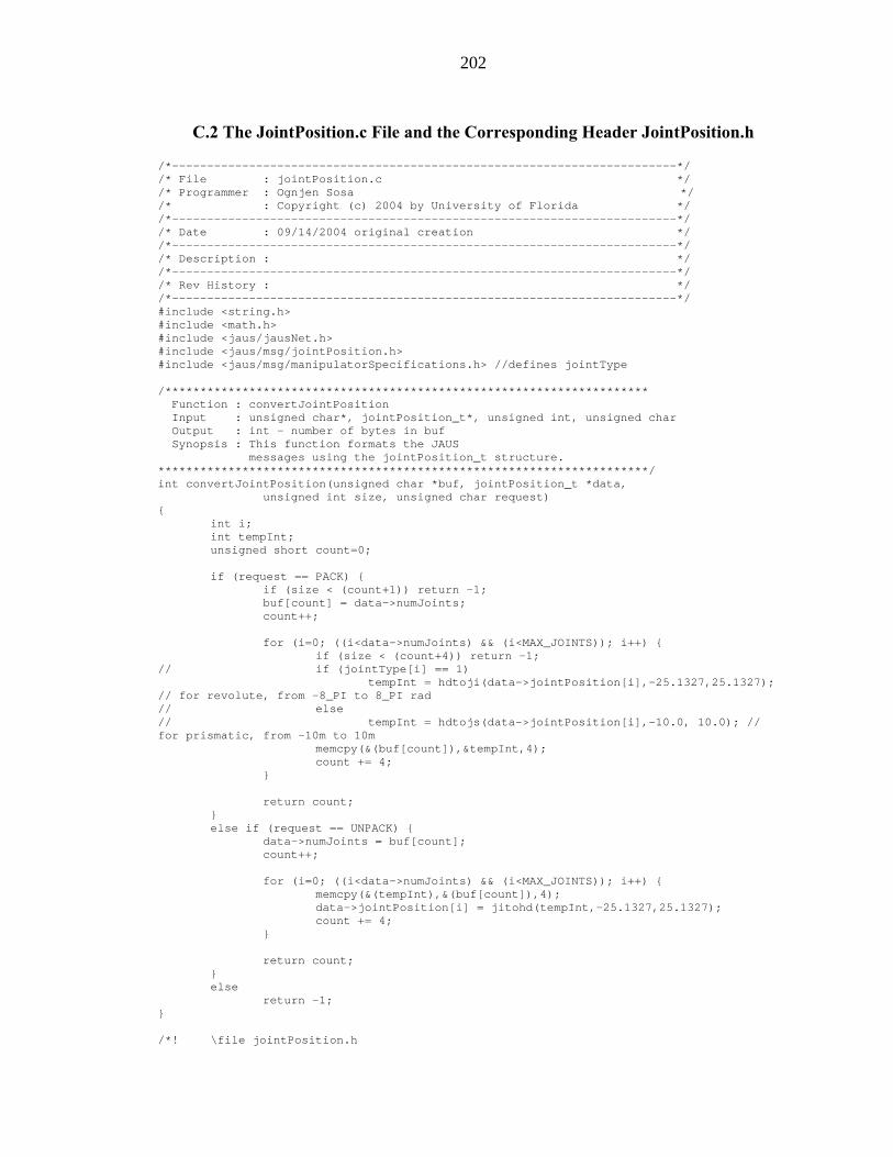
202
C.2 The JointPosition.c File and the Corresponding Header JointPosition.h
/*------------------------------------------------------------------------*/ /* File : jointPosition.c */ /* Programmer : Ognjen Sosa */ /* : Copyright (c) 2004 by University of Florida */ /*------------------------------------------------------------------------*/ /* Date : 09/14/2004 original creation */ /*------------------------------------------------------------------------*/ /* Description : */ /*------------------------------------------------------------------------*/ /* Rev History : */ /*------------------------------------------------------------------------*/ #include <string.h> #include <math.h> #include <jaus/jausNet.h> #include <jaus/msg/jointPosition.h> #include <jaus/msg/manipulatorSpecifications.h> //defines jointType /********************************************************************* Function : convertJointPosition Input : unsigned char*, jointPosition_t*, unsigned int, unsigned char Output : int - number of bytes in buf Synopsis : This function formats the JAUS messages using the jointPosition_t structure. **********************************************************************/ int convertJointPosition(unsigned char *buf, jointPosition_t *data, unsigned int size, unsigned char request) { int i; int tempInt; unsigned short count=0; if (request == PACK) { if (size < (count+1)) return -1; buf[count] = data->numJoints; count++; for (i=0; ((i<data->numJoints) && (i<MAX_JOINTS)); i++) { if (size < (count+4)) return -1; // if (jointType[i] == 1) tempInt = hdtoji(data->jointPosition[i],-25.1327,25.1327); // for revolute, from -8_PI to 8_PI rad // else // tempInt = hdtojs(data->jointPosition[i],-10.0, 10.0); // for prismatic, from -10m to 10m memcpy(&(buf[count]),&tempInt,4); count += 4; } return count; } else if (request == UNPACK) { data->numJoints = buf[count]; count++; for (i=0; ((i<data->numJoints) && (i<MAX_JOINTS)); i++) { memcpy(&(tempInt),&(buf[count]),4); data->jointPosition[i] = jitohd(tempInt,-25.1327,25.1327); count += 4; } return count; } else return -1; } /*! \file jointPosition.h

203
* \author Ognjen Sosa * \par Copyright: * Copyright (c) 2004 by University of Florida. * \date 09/14/2004 * \version 0.02 */ #ifndef __jointPosition_h #define __jointPosition_h #include <jaus/msg/requests.h> #include <jaus/msg/manipulatorSpecifications.h> /* defines MAX_JOINTS */ #ifdef __cplusplus extern "C" { #endif /*! This message is used to set the joint position for a serial mainipulator */ #define SET_JOINT_POSITION 0x0602 /*! This message shall cause the receiving component to reply to the requester * with the message \a REPORT_JOINT_POSITION. */ #define QUERY_JOINT_POSITION 0x2602 /*! This message provides the receiver the current values of the set * joint positions. */ #define REPORT_JOINT_POSITION 0x4602 /*! \struct _jointPosition * This structure contains the data associated with the command codes * \a SET_JOINT_POSITION and \a REPORT_JOINT_POSITION. */ typedef struct _jointPosition { unsigned char numJoints; /*!< 1 to MAX_JOINTS, 0 reserved */ double jointPosition[MAX_JOINTS]; /* -8_PIrad to 8_PIrad for revolute and -10m to 10m for prismatic */ } jointPosition_t; /*! \fn int convertJointPosition(unsigned char *buf, jointPosition_t *data, unsigned int size, unsigned char request); * \brief Packs/Unpacks jointPosition_t to/from the format defined in JAUS Referenc Architecture 3.0 * \param buf The buffer that the JAUS data is unpacked from or packed into. * \param data The data structure that the JAUS data is packed from or unpacked into. * \param size The size of buf. * \param request The requested action, \a PACK or \a UNPACK. * \return The number of bytes in buf on success, -1 on error */ int convertJointPosition(unsigned char *buf, jointPosition_t *data, unsigned int size, unsigned char request); /*! \fn int printJointPosition(jointPosition_t *data); * \brief prints the structure jointPosition_t * \param data The data structure that is to be printed. * \return 0 on success, -1 on error */ int printJointPosition(jointPosition_t *data); #ifdef __cplusplus } #endif #endif

204
C.3 The EndEffectorPose.c File and the Corresponding Header EndEffectorPose.h
/*------------------------------------------------------------------------*/ /* File : endEffectorPose.c */ /* Programmer : Ognjen Sosa */ /* : Copyright (c) 2004 by University of Florida */ /*------------------------------------------------------------------------*/ /* Date : 09/14/2004 original creation */ /*------------------------------------------------------------------------*/ /* Description : */ /*------------------------------------------------------------------------*/ /* Rev History : */ /*------------------------------------------------------------------------*/ #include <string.h> #include <math.h> #include <jaus/jausNet.h> #include <jaus/msg/endEffectorPose.h> /********************************************************************* Function : convertEndEffectorPose Input : unsigned char*, endEffectorPose_t*, unsigned int, unsigned char Output : int - number of bytes in buf Synopsis : This function formats the JAUS messages using the endEffectorPose_t structure. **********************************************************************/ int convertEndEffectorPose(unsigned char *buf, endEffectorPose_t *data, unsigned int size, unsigned char request) { int tempInt; unsigned short count=0; if (request == PACK) { if (size < (count+4)) return -1; tempInt = hdtoji(data->X,-30.0,30.0); // -30m to 30m memcpy(&(buf[count]),&tempInt,4); count += 4; if (size < (count+4)) return -1; tempInt = hdtoji(data->Y,-30.0,30.0); // -30m to 30m memcpy(&(buf[count]),&tempInt,4); count += 4; if (size < (count+4)) return -1; tempInt = hdtoji(data->Z,-30.0,30.0); // -30m to 30m memcpy(&(buf[count]),&tempInt,4); count += 4; if (size < (count+4)) return -1; tempInt = hdtoji(data->quaternionQcomponentD,-1.0,1.0); // -1m to 1m memcpy(&(buf[count]),&tempInt,4); count += 4; if (size < (count+4)) return -1; tempInt = hdtoji(data->quaternionQcomponentA,-1.0,1.0); // -1m to 1m memcpy(&(buf[count]),&tempInt,4); count += 4; if (size < (count+4)) return -1; tempInt = hdtoji(data->quaternionQcomponentB,-1.0,1.0); // -1m to 1m memcpy(&(buf[count]),&tempInt,4); count += 4; if (size < (count+4)) return -1; tempInt = hdtoji(data->quaternionQcomponentC,-1.0,1.0); // -1m to 1m memcpy(&(buf[count]),&tempInt,4); count += 4;

205
return count; } else if (request == UNPACK) { memcpy(&(tempInt),&(buf[count]),4); data->X = jitohd(tempInt,-30.0,30.0); count += 4; memcpy(&(tempInt),&(buf[count]),4); data->Y = jitohd(tempInt,-30.0,30.0); count += 4; memcpy(&(tempInt),&(buf[count]),4); data->Z = jitohd(tempInt,-30.0,30.0); count += 4; memcpy(&(tempInt),&(buf[count]),4); data->quaternionQcomponentD = jitohd(tempInt,-1.0,1.0); count += 4; memcpy(&(tempInt),&(buf[count]),4); data->quaternionQcomponentA = jitohd(tempInt,-1.0,1.0); count += 4; memcpy(&(tempInt),&(buf[count]),4); data->quaternionQcomponentB = jitohd(tempInt,-1.0,1.0); count += 4; memcpy(&(tempInt),&(buf[count]),4); data->quaternionQcomponentC = jitohd(tempInt,-1.0,1.0); count += 4; return count; } else return -1; } /*! \file endEffectorPose.h * \author Ognjen Sosa * \par Copyright: * Copyright (c) 2004 by University of Florida. * \date 09/14/2004 * \version 0.02 */ #ifndef __endEffectorPose_h #define __endEffectorPose_h #include <jaus/msg/requests.h> #ifdef __cplusplus extern "C" { #endif /*! This message is used to set the end effector pose for a serial mainipulator */ #define SET_END_EFFECTOR_POSE 0x0605 /*! \struct _endEffectorPose * This structure contains the data associated with the command code * \a SET_END_EFFECTOR_POSE */ typedef struct _endEffectorPose { double X; /* -30m to 30m */ double Y; /* -30m to 30m */ double Z; /* -30m to 30m */ double quaternionQcomponentD; /* -1m to 1m */ double quaternionQcomponentA; /* -1m to 1m */ double quaternionQcomponentB; /* -1m to 1m */
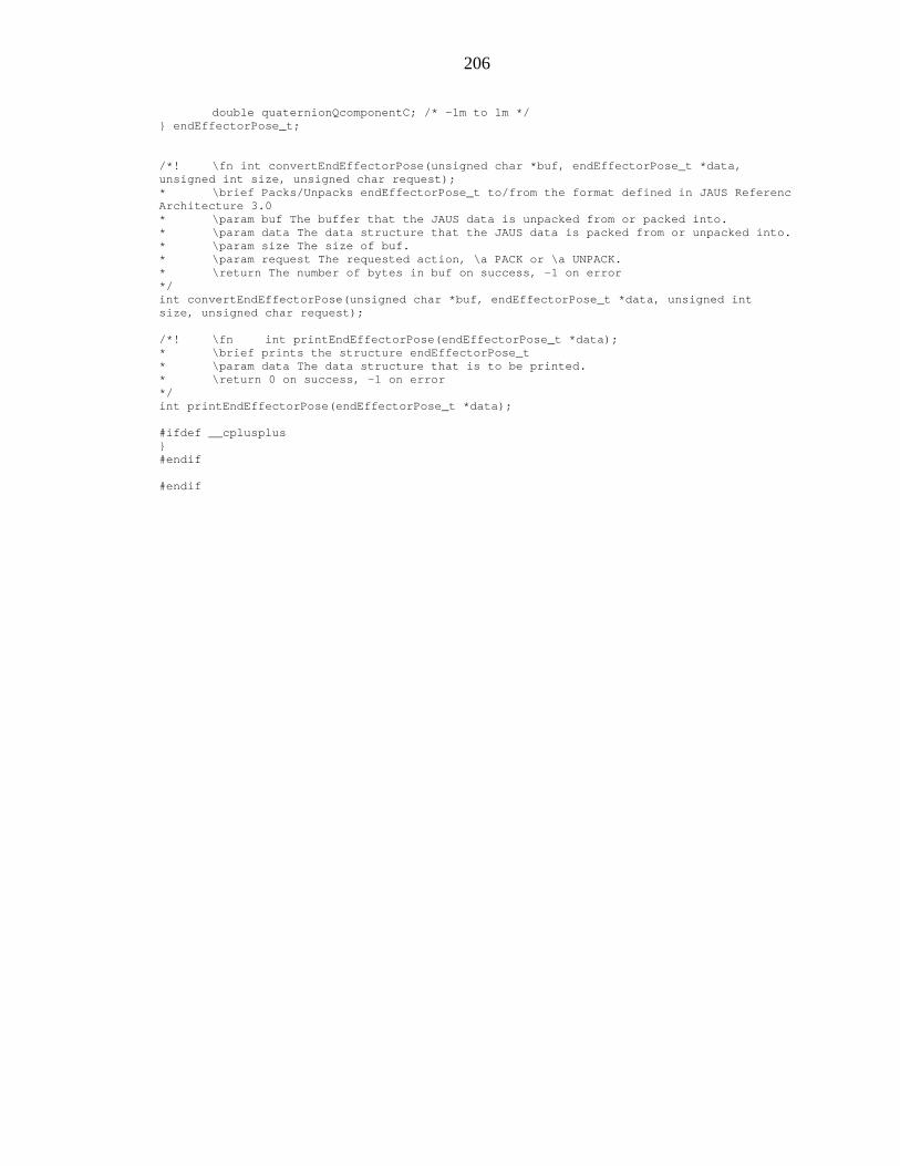
206
double quaternionQcomponentC; /* -1m to 1m */ } endEffectorPose_t; /*! \fn int convertEndEffectorPose(unsigned char *buf, endEffectorPose_t *data, unsigned int size, unsigned char request); * \brief Packs/Unpacks endEffectorPose_t to/from the format defined in JAUS Referenc Architecture 3.0 * \param buf The buffer that the JAUS data is unpacked from or packed into. * \param data The data structure that the JAUS data is packed from or unpacked into. * \param size The size of buf. * \param request The requested action, \a PACK or \a UNPACK. * \return The number of bytes in buf on success, -1 on error */ int convertEndEffectorPose(unsigned char *buf, endEffectorPose_t *data, unsigned int size, unsigned char request); /*! \fn int printEndEffectorPose(endEffectorPose_t *data); * \brief prints the structure endEffectorPose_t * \param data The data structure that is to be printed. * \return 0 on success, -1 on error */ int printEndEffectorPose(endEffectorPose_t *data); #ifdef __cplusplus } #endif #endif

207
LIST OF REFERENCES
1. Das H., Bao X. Bar-Cohed Y., Bonitz R., Lindemann R., Maimone M., Nesnas I., Voorhees C., Robot Manipulator Technologies for Planetary Exploration, Proceedings of the 6P
thP Annual International Symposium on Smart Structures and
Materials, Newport Beach, CA, March 1999.
2. Matthies L., Stereo Vision for Planetary Rovers: Stochastic Modelling to Near Real-time Implementation, International Journal of Computer Vision, Volume 8, pp 71-91, July 1992.
3. Das H., Maimone M., Nesnas I., Autonomous Rock Tracking and Acquisition from a Mars Rover, Proceedings to the 5P
thP International Symposium on Artificial
Intelligence, Robotics and Automation in Space, Noordwijk, Netherlands, June 1999.
4. Yuh J., Underwater Robotic Vehicles: Design and Control, TSI Press Series, Albuquerque, NM, 1995.
5. Sarkar N., Podder T., Motion Coordination of Underwater Vehicle-Manipulator Systems Subject to Drag Optimization, IEEE International Conference on Robotics and Automation, Detroit, MI, pp 387-392, May 1999.
6. Cui Y., Sarkar N., A Unified Force Control Approach to Autonomous Underwater Manipulation, Robotica, Cambridge University Press, pp 255-266, September 2000.
7. JAUS Working Group, 2004, Joint Architecture for Unmanned Systems (JAUS): Reference Architecture Specification, Version 3.2, Volume II, The Joint Architecture for Unmanned Systems, retrieved October 5, 2004, from Hhttp://www.jauswg.orgH, October 2004.
8. Vinch, P., Design and Implementation of an Intelligent Primitive Driver, M.S. Thesis, 2003.
9. Crane C., Duffy J., Kinematic Analysis of Robot Manipulators, Cambridge University Press, University of Florida, Gainesville, FL, 1998.
10. Duffy, J., Crane C., Screw Theory Based Analysis of Robot Manipulators, Center for Intelligent Machines and Robotics, University of Florida, Gainesville, FL, 2000.

208
11. Dowling, K., What’s Available for Puma Manipulators?, retrieved October 13, 2004, from Hhttp://www.frc.ri.cmu.edu/robotics-faq/12.html H, August, 1996.
12. JAUS Working Group, 2004, Joint Architecture for Unmanned Systems (JAUS): Compliance Specification, Version 1.0, The Joint Architecture for Unmanned Systems, retrieved October 6, 2004, from Hhttp://www.jauswg.orgH, July 2004.
13. Unimate Industrial Robots, PUMA 700 Series Mark III – VAL II Equipment Manual, Unimation Inc, Danbury, Connecticut, May 1986.
14. Galil MC, DMC-2x00 Manual Rev. 1.3, Galil Motion Control Inc., Rocklin, California, June 2001.
15. Galil MC, Linux Driver and C/C++ API for PCI/ISA/Ethernet Controllers, Galil Motion Control Inc., Rocklin, California, September 2004.

209
BIOGRAPHICAL SKETCH
Ognjen Sosa was born on February 5, 1979, in Sarajevo, Bosnia and Herzegovina,
to Darko and Jadranka Sosa. He received his Bachelor of Science degree in mechanical
engineering (graduating with honors) from the University of Florida in May 2001. He
then enrolled in the Graduate School of the University of Florida, and obtained a Master
of Science degree in management in June 2003; and a Master of Business Administration
degree in May of 2004. After completing his Master of Engineering degree in mechanical
engineering, he plans to work in the field that will use both technical and business skills
acquired during his studies.