design and function - freepierro777.free.fr/docvag/ssp 273 phaeton convenience (1).pdf2 rear cu to...
TRANSCRIPT

PhaetonConvenience and Safety Electronics
Self-Study Programme 273
Design and Function
Service.

2
Rear CU to door control unit: unlock! "OK!"
Aerial CU to entry and start system: Authorisation OK?
Enty system to rear control unit: Please open!
"Yes,accepted!"
Please enter!
"Request received!"
"Hey aerial:opened!""All clear,
unlocked!"
NEW ImportantNote
This Self-Study Programme explains the design
and function of new developments.
The contents are not updated.
Please always refer to the relevant Service Literature for all
inspection, adjustment and repair instructions.
Further information about the Phaeton can be found in the following Self-Study Programmes:
● Self-Study Programme 250: The Phaeton - W12 - Engine Management● Self-Study Programme 270: The Phaeton● Self-Study Programme 271: The Phaeton - Heating and Air Conditioning System● Self-Study Programme 272: The Phaeton - Onboard Power Supply● Self-Study Programme 274: The Phaeton - Infotainment System● Self-Study Programme 275: The Phaeton - Air Suspension with Dynamic Damping● Self-Study Programme 276: The Phaeton - Automatic Proximity Control● Self-Study Programme 277: The Phaeton - Running Gear
S273_093
Open sesame - thanks to a new system for entry and start authorisation, the Phaeton can be accessed without actively using a key (1). The opening request is detected via an aerial in the outer door handle (2) and authorisation is identified via a control unit (3). The opening request is detected via an aerial in the outer door handle (2) and authorisation is identified via a control unit (3).

3
Introduction . . . . . . . . . . . . . . . . . . . . . . . . . . . . . . . . . . . . . . 4
Entry and start authorisation . . . . . . . . . . . . . . . . . . . . . . . . 8
Convenience system central control unit . . . . . . . . . . . . . 24
Roof module. . . . . . . . . . . . . . . . . . . . . . . . . . . . . . . . . . . . . 32
Multi-function steering wheel. . . . . . . . . . . . . . . . . . . . . . . 52
Sound system. . . . . . . . . . . . . . . . . . . . . . . . . . . . . . . . . . . . 54
Seats . . . . . . . . . . . . . . . . . . . . . . . . . . . . . . . . . . . . . . . . . . . 62
Parking aid. . . . . . . . . . . . . . . . . . . . . . . . . . . . . . . . . . . . . . 72
Test your knowledge . . . . . . . . . . . . . . . . . . . . . . . . . . . . . . 76
Table of Contents

4
Introduction
- the new windscreen wiper system with two separate, electronically controlled motors
- a parking aid that warns against obstacles not only visually, but also acoustically
- the new orientation light for safe entering and exiting in the dark
- the new solar sliding/tilting roof with road speed-dependent wind deflector
This Self-Study Programme provides you with an overview of the complex convenience and safety electronics in the Phaeton. It provides information, for instance, about:

5
- a sound system specially tuned to the car interior
- the new system for entry and start authorisation without the use of a key
- seats adjustable in all directions with air conditioning memory and massage function
- the multi-function steering wheel to operate the main functions
S273_017

6
Drive Train CAN bus
Convenience CAN bus
Infotainment CAN bus
CAN databus
Introduction
System overview of convenience and safety electronics
Legend
Dash panel insert(Gateway)
Steering column electronics control unit
Door control unit, driver's side
Wiper motor control unit (master)
Door control unit, front passenger's side
Control unit for entry and start authorisation
Door control unit, rear right
Door control unit, rear left
Seat adjustment (with memory) control unit, driver
Control unit for tyre pressure monitoring
Central control unit for convenience system
Parking aid control unit
S273_045
Roof electronics control unit
Control unit for air conditioning system
Bootlid control unit
Slave
Front central display and control unit control unit
Onboard power supply control unit
Control unit for air conditioning system
Seat adjustment (with memory) control unit, front passenger
Rear central display and control unit control unit
Seat adjustment (with memory) control unit, rear

7
Component Designation in current flow diagram
Address word for self-diagnosis
Other information
Onboard power supply control unit J 519 09 SSP 272
Roof electronics control unit J 528 38 SSP 273
Gateway in dash panel insert J 533/J 285 19/17 SSP 273
Bootlid control unit J 605 via 46 SSP 273
Convenience system central control unit J 393 46 SSP 273
Entry and start authorisation relay J 518 05 SSP 273
Climatronic control unit J 255 08 SSP 271
Steering column electronics control unit J 527 16 SSP 273
Parking aid control unit J 446 76 SSP 273
Tyre pressure monitor control unit J 502 65 SSP 270
Seat adjustment (with memory) control unit, driver J 136 36 SSP 273
Seat adjustment (with memory) control unit, front passenger
J 521 06 SSP 273
Seat adjustment (with memory) control unit, rear J 522 66 SSP 273
Door control unit, driver's side J 386 via 46 SSP 273
Door control unit, front passenger's side J 387 via 46 SSP 273
Door control unit, rear left J 388 via 46 SSP 273
Door control unit, rear right J 389 via 46 SSP 273
Wiper motor control unit (master) J 400 68 SSP 273
Windscreen wiper control unit, front passenger's side (slave)
J 584 via 68 SSP 273
Control unit, front information display and operating unit
J 523 07 SSP 274
Rear information display and operating unit control unit
J 524 27 SSP 274

8
Entry and start authorisation
Entry and start authorisation switch
Electro-mechanical steering column lock
Gear change mechanism with selector lever lock and button for entry and start authorisation
Complete overview
The adjacent diagram provides an overview of the components involved in the system for entry and start authorisation.

9
S273_090
Entry and start authorisation relay
Interior aerials
Rear aerials in the bumper
Outer door handles with electronics
Ignition key with radio-wave remote control

10
When suitable equipment is available, the convenience functions for the entry and start authorisation system (
Ke
yless
S
tart Exit and
S
ecurit
y
System) make it possible to lock and unlock the vehicle and to switch the engine on and off by radio-wave remote control without actively using the ignition key.
The system is offered in two equipment variants:
●
Basic equipment (standard equipment)
●
Convenience equipment (optional)
Overview of equipment variants
*Terminal 15SV: Power supply of electrical equipment required for startTerminal 15: Power supply ignition "on"Terminal 75x: Power supply/relief relayTerminal 50: Power supply starter/solenoid
Components Basic equipment Convenience equipment
Entry and start authorisation switch X X
Terminal control (Terminal 15SV, 15, 75, 50)* X X
Immobiliser (Immobiliser III) X X
Radio-wave remote control (RRC) for central locking X X
Electro-mechanical steering column lock activation (ESL) X X
Button for entry and start authorisation X
Interior and exterior aerials X
Central locking button in the outer door handles X
Proximity sensors X
Transponder for Immobiliser III and entry and start authorisation
X X
Anti-theft alarm system X
Interior monitor X
Entry and start authorisation

11
Basic equipment for vehicle entry and starting the engine
The vehicle is unlocked using the unlocking button on the ignition key with radio-wave remote control (RRC). To unlock the steering column, the ignition key must be inserted into the entry and start authorisation switch. By means of the immobiliser (coil) in the entry and start authorisation switch, a request is sent to the entry and start authorisation relay for ignition key authorisation. If the control unit makes a positive identification, the steering column is unlocked.
Turning the ignition key in the entry and start authorisation switch switches Terminals 15, 75(X) and 15SV. Further turning (Terminal 50 on) starts the engine, providing the following conditions are met:
●
P/N signal (automatic gearbox)
●
Clutch applied (manual gearbox).
If there is radio interference, or the vehicle or ignition key battery has discharged, the vehicle may be entered using the mechanical emergency lock cylinder in the driver's door or in the bootlid.
S273_055
Ignition key with radio-wave remote control
Entry and start authorisation switch
Entry and start authorisation relay
Electro-mechanical steering column lock
Reader coil
Engine control unit (rpm)
Gearbox control unit
Gate selector lever P/N signal*
* Clutch pedal switch for manual gearbox
Basic equipment components

12
Entry and start authorisation switch
Reader coil
Ignition key with radio-wave remote control
The radio-wave remote control functions in the usual way: to unlock the vehicle door, the unlock button must be pressed on the radio-wave remote control. The control unit for entry and start authorisation evaluates the radio signals. The convenience system central control unit activates the standard functions for the central locking system.
Immobiliser (Immobiliser III)
The immobiliser also functions as before together with the entry and start authorisation switch, which carries the reader coil, and the engine control unit.
Entry and start authorisation switch
The operating concept for the entry and start authorisation switch has been very slightly changed. The positions are:
●
Off = ignition/engine off
●
Zero = Automatic reset of the ignition key after switching on the engine
●
On = ignition on
●
Start = engine on
Entry and start authorisation
S273_050
Unlocking button
ZeroSelect On
Start
S273_047
Switch positions for entry and start authorisation
S273_048

13
Electrical release disable control unit
The electrical release disable control unit ensures that the ignition key cannot be inadvertently removed from the entry and start authorisation switch.
The ignition key cannot be removed while
●
the ignition is on (Terminal 15 on) and
●
if the gate selector lever for the automatic gearbox is not in P position.
S273_051
Dash panel insert
Entry and start authorisation relay
Gate selector lever P signal
Gearbox control unit
Entry and start authorisation switch
Each key fits mechanically into the entry and start authorisation switch and can be turned. Once the ignition key has been authorised (transponder), it is enabled by the immobiliser (IM III).

14
Electro-mechanical steering column lock (ESL)
This is an electro-mechanical version of the conventional mechanical steering column lock, which means that it has an electrical interface to the entry and start authorisation relay and a mechanical interface to the steering column.
The ESL is encoded and activated by means of the entry and start authorisation relay. When the key is inserted or withdrawn, the steering column is locked or unlocked by means of the entry and start authorisation relay. The steering column is supplied with voltage for this procedure only, otherwise the ESL has no voltage (deenergised). The ignition can only be activated when the steering column is unlocked.
Electro-mechanical steering column lock
S273_097
Entry and start authorisation
Entry and start authorisation switch
Entry and start authorisation relay

15
Soft start
The soft start is initiated via the drive train CAN databus between the entry and start authorisation relay and the engine control unit.
If the start position (Terminal 50 on) in the entry and start authorisation switch is flicked, the starter stays in the ON position until the engine is running. To protect the starter and avoid unnecessary noise, the start position of the starter is only activated until the engine has reached idling speed even if the starter is activated for a longer period of time.
Emergency start
If the onboard power supply battery has discharged, an emergency start is possible when the engine is not running by means of the battery management control unit and the entry and start authorisation relay.
The engine control unit receives this message from the engine speed sender and transmits the information to the entry and start authorisation relay, giving the command to shift the starter out of position (Terminal 50 off).
The entry and start authorisation relay switches the following relays:
- Relay Terminal 15: voltage supply- Relay Terminal 15 SV: voltage supply- Relay Terminal 75X: voltage supply- Relay Terminal 50: voltage supply
S273_098
Relay
Dash panel insert
Entry and start authorisation relay
Entry and start authorisation switch
Engine control unit
Please refer to Self-Study Programme 272 of "The Phaeton - Onboard Power Supply" for more detailed information about battery management.

16
Additional convenience equipment functions
Thanks to the additional convenience equipment functions, the ignition key with radio-wave remote control (RRC) is required to open and lock the vehicle, but it no longer needs to be activated. The engine can also be started and switched off without actively operating the ignition key using the authorised transponder.
The additional functions of the convenience equipment are as follows:
●
Opening the vehicle without actively operating the ignition key with the authorised transponder
●
Starting the engine by means of a button for entry and start authorisation without actively operating the ignition key with the authorised transponder
●
Locking the vehicle without actively operating the ignition key with the authorised transponder
Convenience equipment components
Entry and start authorisation
Button for entry and start authorisation
Exterior aerials
Interior aerials
Electro-mechanical steering column lock
Door control unit
Outer door handle with electronics
Aerial
Sensor

17
Engine control unit
Convenience system central control unit
Relay
Ignition key with radio-wave remote control and transponder
Gearbox control unit
S273_101
Entry and start authorisation relay
Entry and start authorisation switch
Entering the vehicle using the convenience equipment
If the user approaches the vehicle with an authorised ignition key, touching the outer door handle with the entry and start authorisation relay transmits an inductive request to the transponder in the ignition key via the exterior aerial in the door handle. If the control unit recognises the ignition key as authorised for entry, it transmits this information to the convenience system central control unit. The convenience system central control unit gives the door control unit the command to unlock the requested vehicle door. The door control unit unlocks the vehicle door.
It is possible to enter the car using any door, opening either a single door or all of the doors, depending on the coding.
If the control unit for entry and start authorisation fails to function, the vehicle door can be unlocked via the emergency lock cylinder in the door lock on the driver's side. The bootlid can be unlocked by means of the emergency lock cylinder in the bootlid (concealed in the VW emblem).
18
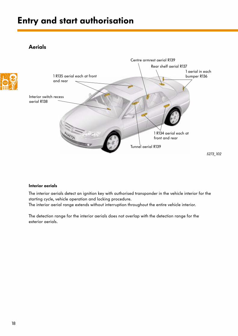
Aerials
Entry and start authorisation
Interior aerials
The interior aerials detect an ignition key with authorised transponder in the vehicle interior for the starting cycle, vehicle operation and locking procedure. The interior aerial range extends without interruption throughout the entire vehicle interior.
The detection range for the interior aerials does not overlap with the detection range for the exterior aerials.
1 aerial in each bumper R136
Interior switch recess aerial R138
Tunnel aerial R139
Centre armrest aerial R139
Rear shelf aerial R137
1 R135 aerial each at front and rear
S273_102
1 R134 aerial each at front and rear

19
Exterior aerials
The exterior aerials detect an ignition key with authorised transponder for the locking and unlocking procedure. The position of the ignition key with authorised transponder can be allocated specifically to the driver's side, front passenger's side or to the bootlid.
The exterior aerials have a range of approximately 1.50 m radiating from the place at which they each operate - vehicle doors and bootlid - at a height of 0.1 m to 1.8 m.
Exterior aerial detection range
S273_056

20
Driver's side and front passenger's side aerials for entry and start authorisation
By means of the aerial in the ignition key with radio-wave remote control and authorised transponder, an encoded signal is transmitted to the aerial in the outer door handle, thus inducing voltage in the aerial. This message is transmitted to the entry and start authorisation relay, which in turn evaluates the signal.
Entry and start authorisation
S273_103
Aerial (coil)
S273_105
Outer door handles with electronics
If convenience equipment is fitted, the aerials, sensors and central locking buttons are located in all outer door handles and may be used to open and close the vehicle doors without actively using the ignition key with radio-wave remote control:
●
one aerial on each of the driver's side and front passenger's side for entry and start authorisation R134, R135*
●
one sensor on each vehicle door for contact on the driver's side G415, G417 and front passenger's side G416, G418
●
one button on each vehicle door for central locking on the driver's side E369, E371 and front passenger's side E370, E372.
*The aerials in the outer door handles should be regarded as a single aerial per vehicle side (front and rear).
Aerial Capacitive sensor Central locking button
S273_109

21
S273_107
Sensors for contact on the driver's side and front passenger's side
If a hand approaches the outer door handle, the capacitance of the sensor in the outer door handle changes. The entry and start authorisation relay recognises the change in the capacitance of the sensor as proximity to the outer door handle or as a request to enter the vehicle.
Buttons for central locking on the driver's side and front passenger's side
Pressure on the central locking button initiates an inductive request through the entry and start authorisation relay to the ignition key with radio-wave remote control and transponder. If the ignition key is recognised as authorised and outside the vehicle but within the range of the vehicle, the command is enabled to lock the vehicle.
S273_104
S273_106
S273_108
Hand operated switch
Capacitive sensor

22
Switching off the engine without an ignition key
The engine can also be turned off with the button for entry and start authorisation. To do this, move the button for entry and start authorisation to the second engaging position by pressing it once.
Starting the engine without an ignition key
For this function the ignition key with authorised transponder need not be inserted into the entry and start authorisation switch. It must, however, be located inside the vehicle interior in order to initiate an inductive request via the interior aerials when the button for entry and start authorisation is moved to the first engaging position.The ignition key gives an encoded response to the entry and start authorisation relay. If the ignition key is identified as authorised, the electro-mechanical steering column lock (ESL) is unlocked and the NO contact activated when the first stage of the button for entry and start authorisation is activated. If the button is then moved to the first engaging position, the ignition is switched on.
Locking the vehicle without an ignition key
Activating a central locking button (fitted to all outer door handles) initiates a request for a valid ignition key with authorised transponder in the exterior of the vehicle. The ignition key transmits a response to the entry and start authorisation relay. Once the ignition key has been positively identified, the vehicle door is locked via the convenience system central control unit.
Entry and start authorisation
Gear change mechanism with selector lever lock
Button for entry and start authorisation
S273_099
S273_100

23
Learning-in the system for entry and start authorisation
As the system contains the immobiliser,
●
the entry and start authorisation relay,
●
electro-mechanical steering column lock (ESL)
●
the ignition key with radio-wave remote control and
●
the engine control unit
have to match one another. This is carried out at the end of the production line or during servicing using the VAS 5051 Diagnostic Testing and Information System.
If the vehicle is locked and a second ignition key with authorised transponder is still located in the vehicle interior, the latter is disabled for start authorisation and the vehicle is locked!
In order to provide better anti-theft protection it is only possible to change just one of the four components; otherwise the system must be subjected to a learn-in process if new components are fitted.
The system for entry and start authorisation has self-diagnostic capability via the addresses
●
05 Control unit for entry and start authorisation and
●
25 Immobiliser III (diverted to 05).