design and field testing of an autonomous underground
TRANSCRIPT

Design and Field Testing of an AutonomousUnderground Tramming System?
Joshua A. Marshall1 and Timothy D. Barfoot2
1 MDA Space Missions, 9445 Airport Road, Brampton, ON L7E 2K9 [email protected]
2 University of Toronto Institute for Aerospace Studies, 4925 Dufferin Street,Toronto, ON M3H 5T6 Canada [email protected]
Summary. This paper describes the design, implementation, and field testing ofan infrastructureless system for autonomous tramming (or hauling) of a center-articulated underground mining vehicle. Described is the development of a fast, re-liable, and robust “autotramming” technology that does not require the installationof fixed infrastructure throughout the mine.
1 Introduction
Mining companies and equipment manufacturers are pursuing improved effi-ciency, productivity, and safety in underground mining operations by robotiz-ing some of the functions of underground vehicles. For example, the repetitive“load-haul-dump” cycle is well suited to automation. In this case, a vehiclecalled a load-haul-dump (LHD) machine is often used to excavate fragmentedrock, haul it to an assigned location, and then dump the material before re-turning for another load (see Figure 1). These vehicles are traditionally drivenmanually by an operator on the vehicle, and more recently by radio remoteand teleoperation [1]. However, the hazardous nature of underground envi-ronments, driver safety and fatigue, labor costs, and the cyclic nature of thistask are all motivations to seek an autonomous tramming solution.
Early “autotramming” attempts worked by outfitting the mine with signal-emitting cables [2], light-emitting ropes [1], or retroreflective tape [3], whichallowed a vehicle to find its way through tunnels by tracking the installedinfrastructure. Other systems have used fixed beacons, placed strategicallythroughout the mine [4].
Existing infrastructureless systems have typically employed a suite of sen-sors for estimating the vehicle’s state with respect to its environment andwith reference to some form of topological map. Unfortunately, systems that? In Proceedings of the 6th International Conference on Field and Service Robotics
(FSR2007), pages 393–402, Chamonix, France, July 2007.

2 Joshua A. Marshall and Timothy D. Barfoot
Fig. 1. LHD test vehicle schematic.
rely entirely on classifying tunnel topology for navigation have been shown tonot operate robustly due to inevitable misclassifications that occur in prac-tice [5, 6, 7, 8]. Inspired by advances in mobile robotics, some have consid-ered the application of alternative poly-line map-based localization techniques[9, 10, 11]. Our approach is similar in philosophy to this work, but is novel ina number of ways. Most notably, we employ a sequence of local self-generatedgrid-type maps [12] rather than use a monolithic map. The use of grid-typemaps makes our system robust in the presence of environmental variations(e.g., non-standard intersections and/or passageways, which occur often inunderground mining) and the use of local maps avoids the need to create aglobally consistent map (i.e., we avoid solving a simultaneous localization andmapping problem).
2 System Architecture and Design
Our autotramming system’s operation consists of three steps:
Teaching. The vehicle is driven along a desired route, either by an operatoron the vehicle, or by remote/teleoperation, while sensor data is logged(front and rear SICK laser rangefinders, a hinge angle encoder, and adrive shaft encoder for measuring displacement of the vehicle).
Route Profiling. Data logged during the teaching step is processed (offline)and converted into a format suitable for use by the estimation and controlalgorithms during playback. The output is referred to as a route profile,which contains information about the traveled path, a sequence of over-lapping metric maps along the path, a record of any pause points (e.g., fordumping material), as well as a vehicle speed profile to be tracked duringplayback. Loading and dumping are beyond the scope this paper but oursystem is compatible with manual or automated loading/dumping.

An Autonomous Underground Tramming System 3
Playback. In this step, the system autonomously plays back a route profilegenerated by the teaching and route profiling steps. During playback,data from the specified route profile is used by navigation and guidancealgorithms to estimate longitudinal, lateral, heading, and vehicle speederrors at discrete instants. The control system then stabilizes these errorsso that the vehicle follows the profiled path at the desired speed.
Once profiled, a route can be played back many times. It is expected thatre-profiling would only be necessary if significant changes to the environmentwere made; e.g., due to excavation. Since the vehicle is driven along a collision-free path during teaching, complex path planning is not required. However,the system does include short-range guidance algorithms designed to stop thevehicle should the profiled path be subsequently obstructed during playback.
2.1 Route Profiling and Atlas Maps
A route profile consists of four components: a path profile, a pause profile,a sequence of locally-consistent metric maps, and a speed profile. Firstly, asequence of locations that are equally spaced (typically 0.5 m) along the pathare created, called path points. We then associate with each path point theconfiguration of the vehicle at that point during the teaching step by inter-polating the preprocessed logged data. Thus, the sequence of path points andassociated data comprise the path profile.
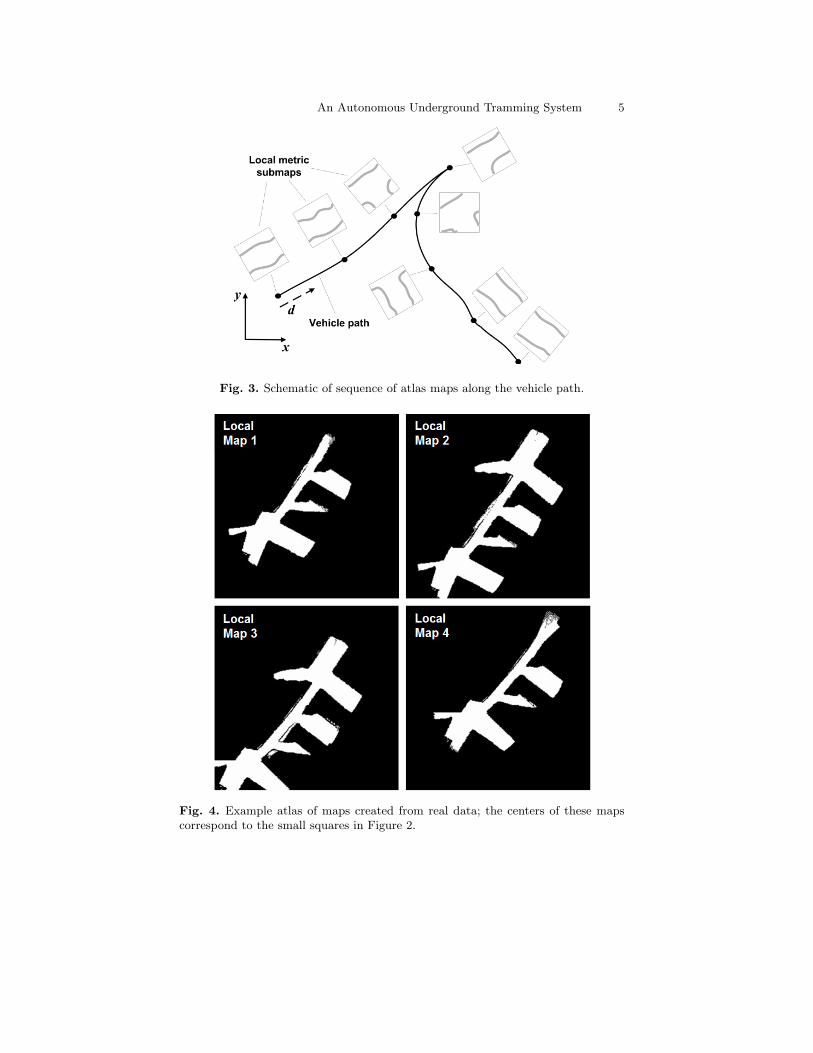
Locally-consistent metric maps of the mine environment along the pathprofile are generated using both odometry and rangefinder data. Each map isan occupancy grid [13]. For localization in underground mines, this approachis much more flexible than a system that must classify tunnel topology inthat it will work regardless of the shape of the walls, so long as the mapsare of sufficient resolution. However, the use of a single monolithic map torepresent the mine environment suffers from two key problems. Firstly, insome situations high memory usage is required. Secondly, map inconsistenciescan result on longer traverses when a vehicle closes a loop or crosses its ownpath (e.g., see Figure 2). To address these problems, we employ a sequenceor atlas of metric maps attached along the path to form an overall routeprofile; which is to say, the system does not rely on one monolithic map andan absolute frame of reference. The underlying idea is to create a situation inwhich the vehicle’s path exists in a high-dimensional space wherein it neverintersects itself [12].
Figure 3 illustrates this notion. A locally-consistent metric map is asso-ciated with each position (x, y, d) along the vehicle path, where (x, y) is thevehicle’s location in the mine and d its distance along the path. Figures 2 and4 show example monolithic and atlas maps generated from real data acquiredduring one of our field tests. The monolithic map has a resolution of 0.3 m,while the atlas maps each have a resolution of 0.1 m.

4 Joshua A. Marshall and Timothy D. Barfoot
Fig. 2. Example monolithic occupancy grid created from real data, with vehiclepath shown; the small squares indicate the centers of the atlas maps in Figure 4;the circle with cross hairs indicates a pause point.
2.2 Playback
Our objective was to create a system that permits a large articulated vehicleto robustly track the path specified by a route profile. During playback, thishas been achieved through the design of a two-timescale control system. At theslower timescale, or outer loop, are localization and path-tracking algorithmsthat work to reject lateral and heading path errors. At the faster timescale, orinner loop, are rate estimators and two controllers that track reference steeringrates and vehicle speeds. The underlying justification for this two-timescaledesign is founded on the assumption that we can specify sufficient bandwidthseparation between the nested control loops.
An Autonomous Underground Tramming System 5
Fig. 3. Schematic of sequence of atlas maps along the vehicle path.
Fig. 4. Example atlas of maps created from real data; the centers of these mapscorrespond to the small squares in Figure 2.

6 Joshua A. Marshall and Timothy D. Barfoot
Metric Map Localization
The localization problem solved here is one of estimating the vehicle’s poseas it travels through a (locally) known environment. Recently, a number oftechniques have been developed in the mobile robotics community that globallylocalize a robot in a known environment. Many of these techniques use aparticle filter representation of the vehicle’s pose [14]. An initial design usinga particle filter was shown to work in simulation, but required the use of toomany particles (e.g., > 100) for convergence from a reasonable initial poseestimate. Variations requiring fewer particles and computational resourcesexist, but are complex to implement. Moreover, the task at hand does notactually require a solution to the global localization problem. Instead, we choseto implement a variation of the Unscented Kalman Filter (UKF) [15, 16] toposition with respect to the locally consistent submaps defined during routeprofiling. The inputs to the UKF algorithm are the laser rangefinder data aswell as wheel odometry (i.e., hinge angle and wheel speed); the final outputsare heading and lateral errors of the vehicle with respect to the profiled path.Figure 5 shows how the laser rangefinder data is used to determine these path-tracking errors.
Fig. 5. Laser data is used to position within the local submap (which is attachedto the vehicle path). It is then straightforward to determine the vehicle errors withrespect to the path.
Path Tracking
A path-tracking controller is required to guide the vehicle along the pathspecified by the route profile. Path-tracking control for articulated vehicleshas been extensively discussed in the engineering literature, yet there is somedisagreement over the form such a controller should take. Some researchersargue that the position of both front and rear components of the vehicle shouldbe tracked; others suggest that wheel slip should be explicitly accounted for

An Autonomous Underground Tramming System 7
[17]. We have found that, in practise, neither of these tasks are necessaryunder a two-timescale control architecture if inner-loop controllers are robustenough to handle these model uncertainties. Moreover, we have found thatrejection of only the heading error and lateral error of the front component(when traveling forward) is necessary. We obtain these error signals from theUKF algorithm and then employ a nonlinear controller, based on feedbacklinearization, to drive them to zero, thereby forcing the vehicle to track theprofiled path.
3 Underground Field Trials
Field testing of the autotramming system was carried out during April 2006.Realistic test scenarios were devised and manual baseline times for traverseswere obtained by timing the performance of a human operator driving thesame route as the autotramming system. More than 100 tests were performedduring integration and testing.
3.1 System Integration
The autotramming system design was initially created through modeling andsimulation and then field tested on a 10-tonne capacity LHD, shown in Fig-ure 6. The autotramming code was run on a real-time operating system, withcontrol and localization algorithms updated at 25 Hz. SICK rangefinders with180◦ field of view were used.
Fig. 6. 10-tonne capacity test LHD, with sensor layout.
3.2 Field Testing Summary
A total of eight test scenarios were conducted: T1, T2, T3 T4E, T4L, T5E,T5L, T7. Figure 2 shows the layout of the T5 scenarios, which involved backingout of a crosscut containing a load point, switching directions and proceedingat high speed down the main drift (with < 1 m side clearance), parking at

8 Joshua A. Marshall and Timothy D. Barfoot
dump point, and then reversing this sequence to return to the load point. Eachtest was several hundred meters in total tramming distance. Some scenarioswere conducted with the LHD bucket both empty, denoted ‘E’, and loaded,denoted ‘L’, to evaluate the performance of the system in both cases.
Average operator times for seven test scenarios are shown in Table 1 to-gether with measured average times taken by the autotramming system tosuccessfully complete the same route. Note that, in some cases the autotram-ming system actually performed better than the human operator. By examin-ing the speed data logs, it was found that a manual operator is generally fasterat performing direction switches, while the autotramming system can oftenperform faster on straight routes, especially when the drift width is small.
Table 1. Average manual baseline times (in seconds).
Test Scenario T1 T2 T3 T4E T4L T5E T5L Total
Human Operator 41.8 27.0 57.0 85.0 90.0 81.0 83.0 464.8
Autotramming 41.3 25.8 59.5 97.3 89.8 81.8 85.0 480.5
Markings made on the ground were used to estimate the positioning accu-racy and repeatability of the autotramming system. An example photographdepicting this procedure is provided in Figure 7. The markings on the mea-surement ruler are spaced at 10 cm intervals. The measured errors for all testsare provided in Table 2, which can also be used to infer repeatability. For theT5 cases, the position error was measured at the dump point, denoted ‘a’,and the end of the route, denoted ‘b’.
Fig. 7. Example positioning measurement from a test run, where the orthogonallines marked ‘T2’ show the desired pose of the wheel’s outer edge.
In all but one test case the vehicle positioned within the ±50 cm toleranceset as a project goal. In this particular case, poor ground conditions con-tributed to a larger than normal longitudinal error. The target finishing point

An Autonomous Underground Tramming System 9
happened to be located on just the other side of a significant pothole, whichforced the vehicle to increase throttle in order to get out of the hole, causingthe vehicle to overshoot the target. It should be noted that the errors weregenerally very consistent within a given test scenario, most likely owing to thefact that the same route profile was used for each test run. It should be possi-ble to remove a large portion of these systematic errors through route-specifictuning of the route profile.
Table 2. Longitudinal and lateral positioning errors (cm) covering all measuredstops for the relevant test runs.
Error / Test T1 T2 T3 T4E T4L T5Ea T5Eb T5La T5Lb T7
Long. 0 5 -10 -22 -20 60 -20 40 -25 00 0 -10 -20 -30 60 -25 30 -25 50 5 -10 -25 -15 80 -20 35 -25 5-5 0 -10 -30 -20 70 -25 30 -20 5
Lat. 45 10 0 -15 -10 0 20 10 -10 1540 10 0 -15 -15 0 25 0 -15 540 10 0 -15 -10 20 20 10 -10 545 15 0 -10 -10 20 20 0 -10 0
4 Conclusion
The autotramming system described in this paper was designed with the aimof overcoming the speed and robustness deficiencies of existing technologies byapplying map-based localization using an atlas of metric maps together witha suitable control architecture. Given the dynamic and unstructured natureof underground mines and the difficulties in controlling large hydraulicallyactuated vehicles, the presented results are very encouraging. The system hasnow been successfully operating in an underground mine test environment formore than 12 months (at the time of writing).
This is not to say that limitations do not exist and that challenges do notremain. The present design requires that individual routes be taught manually;this is because a global map of the mine environment is never generated. Itwould be a useful feature to have some form of globally consistent map fromwhich route profiles could be derived without requiring that the route beingphysically taught.
Acknowledgments
We would like to acknowledge R. Corcoran, D. Parry, R. Jakola, R. Ward,L. Bloomquist, and the many others who contributed to this project’s success.

10 Joshua A. Marshall and Timothy D. Barfoot
References
1. G. R. Baiden. Combining teleoperation with vehicle guidance for improvingLHD productivity at Inco Ltd. CIM Bulletin, 87(981):36–39, June 1994.
2. K. Amdahl and M. Lundstrom. Automatic truck saves money underground.World Mining, pages 40–44, November 1972.
3. U. Wiklund, U. Andersson, and K. Hyypa. AGV navigation by angle measure-ments. In Proceedings of the 6th International Conference on Automated GuidedVehicle Systems, pages 199–212, Brussels, Belgium, October 1988.
4. S. Scheding, G. Dissanayake, E. M. Nebot, and H. Durrant-Whyte. An ex-periment in autonomous navigation of an underground mining vehicle. IEEETransactions on Robotics and Automation, 15(1):85–95, February 1999.
5. V. Beranger and J.-Y. Herve. Recognition of intersections in corridor environ-ments. In Proceedings of the 13th International Conference on Pattern Recog-nition, pages 133–137, Vienna, Austria, August 1996.
6. J. Steele, C. Ganesh, and A. Kleve. Control and scale model simulation of sensor-guided LHD mining machines. IEEE Transactions on Industry Applications,29(6):1232–1238, November/December 1993.
7. J. M. Roberts, E. S. Duff, P. I. Corke, P. Sikka, G. J. Winstanley, and J. B.Cunningham. Autonomous control of underground mining vehicles using reac-tive navigation. In Proceedings of the 2000 IEEE Conference on Robotics andAutomation, pages 3790–3795, San Francisco, CA, April 2000.
8. D. Silver, D. Ferguson, A. Morris, and S. Thayer. Feature extraction for topo-logical mine maps. In Proc. of the 2004 IEEE/RSJ International Conference onIntelligent Robots and Systems, pages 773–779, Sendai, Japan, September 2004.
9. G. K. Schaffer, A. Stentz, W. L. Whittaker, and K. W. Fitzpatrick. Positionestimator for underground mine equipment. IEEE Transactions on IndustryApplications, 28(5):1131–1140, September/October 1992.
10. R. Madhavan, M. W. M. G. Dissanayake, and H. F. Durrant-Whyte. Au-tonomous underground navigation of an LHD using a combined ICP-EKF ap-proach. In Proceedings of the 1998 IEEE Conference on Robotics and Automa-tion, pages 3703–3708, Leuven, Belgium, May 1998.
11. H. Makela. Overview of LHD navigation without artificial beacons. Roboticsand Autonomous Systems, 36:21–35, 2001.
12. A. Howard. Multi-robot mapping using manifold representations. In Proceedingsof the IEEE International Conference on Robotics and Automation, pages 4198–4203, New Orleans, Louisiana, 2004.
13. A. Elfes and H. Moravec. High resolution maps from wide angle sonar. In Proc.of the IEEE Int. Conf. on Rob. and Aut., pages 116–121, St. Louis, MO, 1985.
14. S. Thrun, D. Fox, W. Burgard, and F. Dellaert. Robust Monte Carlo localizationfor mobile robots. Artificial Intelligence, 128(1–2):99–141, 2001.
15. S. Julier and J. Uhlmann. A general method for approximating nonlinear trans-formations of probability distributions. Technical report, Department of Engi-neering Science, University of Oxford, Oxford, UK, November 1996.
16. E. A. Wan and R. van der Merwe. The unscented kalman filter for nonlinearestimation. In Proc. of the IEEE AS-SPCC, Lake Louise, AB, October 2000.
17. P. Ridley and P. Corke. Autonomous control of an underground mining vehicle.In Proceedings of the 2001 Australian Conference on Robotics and Automation,pages 26–31, Sydney, Australia, November 2001.