design and fatigue life estimation of diesel engine … · life, endurance limit, discretization 1....
TRANSCRIPT
International Research Journal of Engineering and Technology (IRJET) e-ISSN: 2395-0056
p-ISSN: 2395-0072 Volume: 04 Issue: 06 | June -2017 www.irjet.net
© 2017, IRJET | Impact Factor value: 5.181 | ISO 9001:2008 Certified Journal | Page 3307
DESIGN AND FATIGUE LIFE ESTIMATION OF DIESEL ENGINE PISTON USING ANSYS AND FESAFE
Divyarathi, Mohammed Rafi H Kerur
Department of Mechanical Engineering P E S College of Engineering, Mandya-571401, Karnataka, India
---------------------------------------------------------------------***--------------------------------------------------------------------- Abstract: In this project use Ansys and Fesafe software tools helps in determining the stress distribution and concentration and estimating the fatigue life of the component in a cost effective and time reducing manner. It deals with how the mesh size affects the stress values based on the grid independence study carried out for three different mesh sizes. It discusses with the calculation of S-N curve with and without temperature correction factor and the estimation of fatigue life for gas pressure load. It also deals with the temperature distribution on the piston in a thermo mechanical analysis carried out to estimate the fatigue life of the piston for combined loading. Finally it describes how the fatigue life of the piston is reduced when both gas pressure and temperature acts on the piston as in real life scenario.
Keywords: Dynamic load, Fatigue life, S – N Curve, Fatigue life, Endurance limit, Discretization
1. INTRODUCTION:
Now a days in the automobile industries the part of an engine which is mainly subjected for the high stresses like mechanical and thermal, by this the difference in temperature is very large in between the crown of piston and the galleries arranged for the cooling carries the high thermal stress of piston. Piston acceleration develops the mechanical stress by striking the piston side walls this is also imposed of the thermal stress. The failure of piston is caused due to the thermo-mechanical stresses. So the discussion has been made on the thermal and mechanical stresses applied on the piston to improve the performance. After the implementation of the new technologies piston damage causes, by considering thermal and mechanical fatigue the designing of piston is done. Tests are carried out by the large production of piston by considering the fatigue factors with the involvement of cost and the time. To characterise stresses, deformations, gradients of temperature and fatigue are determined by using the finite element analysis. Analysis results are taken as guidelines, it can be taken as guide lines for the design of engine to improve the efficiency and performance of the engine.
Piston is a member which transmits the expanded gas energy in to the mechanical energy. The piston moves in the inside lining of the cylinder, normally pistons are made up of cast iron alloy or from the aluminium alloys.
In this project, the loading cycle applied on the Diesel engine piston during the motion of the piston with velocity 6 m/s, also a simple structural analysis was carried out on the piston by taking peak load from the ADAMS software. 1.1 Design consideration for a Piston:
In designing a piston, the following points should be taken into consideration:
It should have enormous strength to withstand the
high gas pressure and inertia forces. It should have minimum mass to minimise the
inertia forces. It should form an effective gas and oil sealing of the
cylinder. It should provide sufficient bearing area to prevent
undue wear. It should disperse the heat of combustion quickly to
the cylinder walls. It should have high speed reciprocation without
noise. It should be of sufficient rigid construction to
withstand thermal and mechanical distortion. It should have sufficient support for the piston pin.
2. OBJECTIVES:
Reverse engineering of the Four wheeler engine
piston to generate 3D CAD model. Design modification of the piston based on
conclusions obtained from the literature review. Simulation of the engine with redesigned piston for
a selected velocity to get dynamic load date. Structural analysis of the redesigned piston for
checking stress concentration.
Re designing the piston to reduce stress levels if any.
Fatigue life estimation for a designed piston. 3. ANALYSIS: Design specification for piston:

International Research Journal of Engineering and Technology (IRJET) e-ISSN: 2395-0056
p-ISSN: 2395-0072 Volume: 04 Issue: 06 | June -2017 www.irjet.net
© 2017, IRJET | Impact Factor value: 5.181 | ISO 9001:2008 Certified Journal | Page 3308
Table 1: Design specification
Sl no Design-dimensions Size in mm 1 Length of the piston 80 2 Diameter of the
piston 100
3 Thickness 10
Fig 1: Geometric model of the Piston
The geometric model of the piston is created using CATIA software to carry out the fatigue analysis on the piston. Since this assignment deals only with the comparison of fatigue life of the piston with and without thermal load considerations so a simplified model without the piston ring grooves and swirl region is created to avoid the complexities in meshing.
3.1 Meshing the model:
The geometric model of the piston is imported into the Hypermesh software to generate the finite element model. The piston is meshed with triangular elements using 3D tetrahedral mesh option with an element size of 4. Fig4.2 shows the FE piston model meshed with triangular elements of second order. Second order element is used to get more accurate results.
Fig 2 :FE model of piston
After the quality check the material properties is
assigned for the piston in the same Hypermesh software. Here AISI 1040 chrome molybdenum high tensile steel is used as piston material since most of the recent day’s piston are manufactured using this type of steel.
The properties of this steel was applied to the piston model by creating a material set in which the values of density ρ = 7860 kg/m3, Young’s Modulus E = 205GPa and Poisson’s ratio υ = 0.3 were entered. The element type was set as ‘Solid 186’ since both mechanical and thermal analysis is to be carried out. Also this element type was selected because of the use of second order triangular elements. Then the meshed file was exported as ‘.cdb’ file to input into Ansys software. Determination of the Loading Cycle:
In order to apply pressure load on the piston the inertial loads of the piston were calculated as loading cycles by using Adams software. The entire engine assembly model was created using Catia and the assembly was exported as ‘Parasolid’ model to input the assembly into Adams environment. After importing the engine assembly the same AISI 1040 steel material properties were applied to all the engine components. Then the gravity was defined and the respective joint constraints were defined for the entire model. The different joints defined for the engine model in which the revolute joint specified in the crank was given a motion of 83 deg/sec for the piston to reach a velocity of 6 m/s.
The inertial force of the engine which was measured from the translational joint specified between the piston and the cylinder. It can be seen that the maximum inertia force (IF) is 461.64 N for the piston velocity of 6 m/s. 3.2 Calculation of Total Pressure acting on the Piston: The total pressure acting on the piston is calculated by subtracting the inertial loads from the gas pressure loads. So for the 100 mm diameter CI engine piston the gas force is taken as 96000 N. Total Force acting on the Piston:
F = Gas Force – Inertia Force
= 96000 – 461.64
F = 95538.36 N Total Pressure acting on the Piston:
P = Total Force acting on the Piston / Piston Area
= 95538.36 / (π * 502) = 12.16MPa
3.4 Boundary Conditions for the Piston:
To carry out the structural static analysis on the piston model without the thermal load considerations the gas pressure of 12.16MPa was applied on the top surface of the piston and the displacement constraint was applied on the nodes of the gudgeon pin hole with all DOF (degrees of

International Research Journal of Engineering and Technology (IRJET) e-ISSN: 2395-0056
p-ISSN: 2395-0072 Volume: 04 Issue: 06 | June -2017 www.irjet.net
© 2017, IRJET | Impact Factor value: 5.181 | ISO 9001:2008 Certified Journal | Page 3309
Mesh Type Element Size
Stress (MPa) Error (%)
Fine 4 290.622 1.91
Intermediate 6 265.532 10.56
Coarse
8
194.555
34.47
freedom) arrested. Figure shows the boundary conditions applied to the piston model in Ansys. The gas pressure is applied on the top surface of the piston because during the combustion process the maximum pressure acts directly on the piston head and the displacement constraint was applied to piston pin holes because piston will move from TDC to BDC with the help of fixed support at pin holes. Also in a journal paper ‘Fatigue on engine pistons’ the same boundary conditions were applied on the piston to carry out the static analys.
Pressure
12.16MP
1040 steel is ductile in nature Von Mises stress is used to identify the vulnerable spot. After creating three different FE models with fine, intermediate and coarse mesh the same boundary condition like pressure in the top surface nodes and displacement constraint in the gudgeon pin holes with all DOF restrained were applied for all the three models. The Von Mises stress distribution with a maximum stress of 290.622MPa in the inner top surface of the piston and a maximum deflection of 0.081297 mm for the fine mesh with element size 4. Percentage Error Comparison for Different Element Size: Table2: % error comparison for different element size
Displac
ement
of all
Fig 3: Boundary Conditions
4.RESULT AND DISCUSSIONS
4.1 Stress Distribution on the Piston:
In case of fatigue failure there two important stress
that are to be considered. If the material is ductile in nature and if it fails when the stain energy reaches above the yield stress of the material (415 MPa for Piston) then Von Mises stress is suitable for identifying the vulnerable spots.
F
Fig 4: Von Mises Stress Plot of the Piston
Fig shows the Von Mises stress distribution on the piston. Here it can be seen that the vulnerable red spots is in the region where its cross section changes. In this failure the material has a slow propagation and large amount of energy absorption (plastic deformation) before fracture. Since AISI
Table 2 shows the percentage error calculated for three different mesh sizes. In this the fine mesh is considered to give more accurate results and based on this the error for intermediate and coarse mesh were calculated for the maximum stress. 4.2 Theoretical Stress Calculation: The piston crown is designed for bending by maximum gas forces Pzmax as uniformly loaded round plate freely supported by a cylinder. The stress acting in MPa on piston crown. ςb=Mb/Wb=Pzmax (ri/δ)2 (1) Where , Mb = (1/3)Pzmax*ri³ is the bending moment, MN -m; Wb= (1/3)ri *δ² is the moment of resistance to bending of a flat crown, m³; Pzmax= Pz, is the maximum combustion pressure, MPa=12.16Mpa This value varies from 10Mpa-20Mpa. ri= [D / 2- (s + t1 + dt)]is the crown inner radius, m.; Where, Thickness of the sealing part s = 0.05D= 0.05X100=5mm. Radial clearance between piston ring: dt= 0.0008m Radial thickness of ring (t1) =2.25mm. Therefore, ri=[0.1/2-(0.005+0.0025+0.0008)]=0.042m Thickness of piston crown δ=(0.08 to 0.1)*D= 0.085*100=0.0085mm. ςb= 12.16X[(0.042/0.0085)^2]= 296.89Mpa. Hence required theoretical stress obtained from calculation is 296.89Mpa.

International Research Journal of Engineering and Technology (IRJET) e-ISSN: 2395-0056
p-ISSN: 2395-0072 Volume: 04 Issue: 06 | June -2017 www.irjet.net
© 2017, IRJET | Impact Factor value: 5.181 | ISO 9001:2008 Certified Journal | Page 3310
4.3 Estimation of Fatigue Life of Piston without Temperature Factor Considered:
The estimation of fatigue life of the piston was
carried out in Fesafe software. In order to estimate the life of the component without temperature factor considerations the temperature data was unchecked in Ansys RST interface option. The FE model was given as input file in Fesafe by reading the ‘.rst’ file generated from Ansys software. Then the material was defined as ductile material with Ultimate Strength ςu = 655MPa, Young’s Modulus E = 205GPa, Poisson’s ratio υ =0.3 and S-N curve values. Also the loading cycle was defined based on the load curve obtained using ‘Adams’. Then the algorithm was set to Uniaxial Stress Life Goodman.
Fig 5 :Fesafe Analysis Window
After setting the material properties and algorithm the result file was analyzed and it showed a worst life of 2.184 x 10⁶ cycles which is shown in fig5. Since it has worst life above 6lakh cycles the piston is said to have infinite life which can be observed from the S-N curve shown in figure Also the piston is a critical component in the engine it will be designed for infinite life.
Fig 6: Fatigue Life of the Piston without Temperature
Correction Factor
In order to estimate the vulnerable spot for fatigue in the piston, the result file generated in Fesafe was viewed in Ansys. The vulnerable spots or critical spots in which the crack will initiate or will fail due to fatigue. It can be seen that the maximum life cycle of the piston is 7.699 i.e. Antilog
(7.699) = 5x10⁷ cycles which is represented by the red region. The blue spots indicate the low cycle fatigue region and the minimum life cycle is 6.348 i.e. Antilog (6.348) = 2.23x10⁶ cycles. It can also be seen that this minimum life is in the inner top surface region of the piston. It can be validated by considering the Von Mises stress plot in which the maximum stress concentration is also in the same region which can be seen in fig6. Estimation of Fatigue Life with both Structural and Thermal Loads: 4.4 Thermal Boundary Condition:
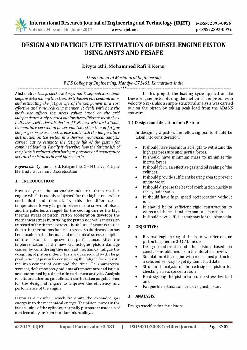
For the fatigue analysis of piston with combined loading, both thermal and mechanical loads are applied in Ansys. This is because in real life scenario both these loads act on the piston simultaneously so for this first the thermal analysis is to be carried out so in the material properties the thermal conductivity was defined as k = 93.9 W.m-1k-I.. The boundary conditions applied to the FE model with element size 4. Here the top surface of the piston was applied with temperature boundary condition of 773 K (500°C) and convection boundary condition with heat transfer coefficient of 2724 W/m2.K and bulk temperature of 303 K (30°C). Also another convection boundary condition with heat transfer coefficient value of 91 W/m2.K and bulk temperature of 303 K (30°C) was applied on the side skirts. Also for convection boundary condition in the piston top surface the heat transfer coefficient was taken as 2724 W/m2.K because the convection takes place between the air and the piston. But in case of the piston side skirt the heat transfer coefficient was taken as 91 W/m2.K because the convection takes place between piston wall and oil. 4.5 Temperature Distribution on the Piston: After the application of the thermal boundary conditions the Ansys file was solved and the temperature distribution across the piston was studied using nodal temperature plot. Fig3.6.2 shows the temperature distribution over the piston. It can be seen that the maximum temperature is 773 K which was the given input temperature and this is represented as the red region which can be seen on the top surface of the piston and this is because during combustion the temperature in thi region reaches this level. Also it can be seen that the temperature gradually reduces while moving downwards along the length of the piston and this is because of the convection that takes place between the oil and the piston wall.
International Research Journal of Engineering and Technology (IRJET) e-ISSN: 2395-0056
p-ISSN: 2395-0072 Volume: 04 Issue: 06 | June -2017 www.irjet.net
© 2017, IRJET | Impact Factor value: 5.181 | ISO 9001:2008 Certified Journal | Page 3311
4.6 Estimation of Fatigue Life of Piston with Temperature Factor Considered:
The fatigue life of the piston was estimated by
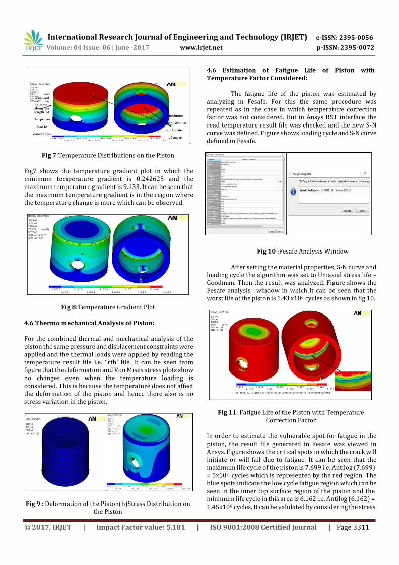
analyzing in Fesafe. For this the same procedure was repeated as in the case in which temperature correction factor was not considered. But in Ansys RST interface the read temperature result file was checked and the new S-N curve was defined. Figure shows loading cycle and S-N curve defined in Fesafe.
Fig 7:Temperature Distributions on the Piston
Fig7 shows the temperature gradient plot in which the minimum temperature gradient is 0.242625 and the maximum temperature gradient is 9.133. It can be seen that the maximum temperature gradient is in the region where the temperature change is more which can be observed.
Fig 8:Temperature Gradient Plot
4.6 Thermo mechanical Analysis of Piston:
For the combined thermal and mechanical analysis of the piston the same pressure and displacement constraints were applied and the thermal loads were applied by reading the temperature result file i.e. ‘.rth’ file. It can be seen from figure that the deformation and Von Mises stress plots show no changes even when the temperature loading is considered. This is because the temperature does not affect the deformation of the piston and hence there also is no stress variation in the piston.
Fig 9 : Deformation of the Piston(b)Stress Distribution on the Piston
Fig 10 :Fesafe Analysis Window
After setting the material properties, S-N curve and loading cycle the algorithm was set to Uniaxial stress life – Goodman. Then the result was analyzed. Figure shows the Fesafe analysis window in which it can be seen that the worst life of the piston is 1.43 x10⁶ cycles as shown in fig 10.
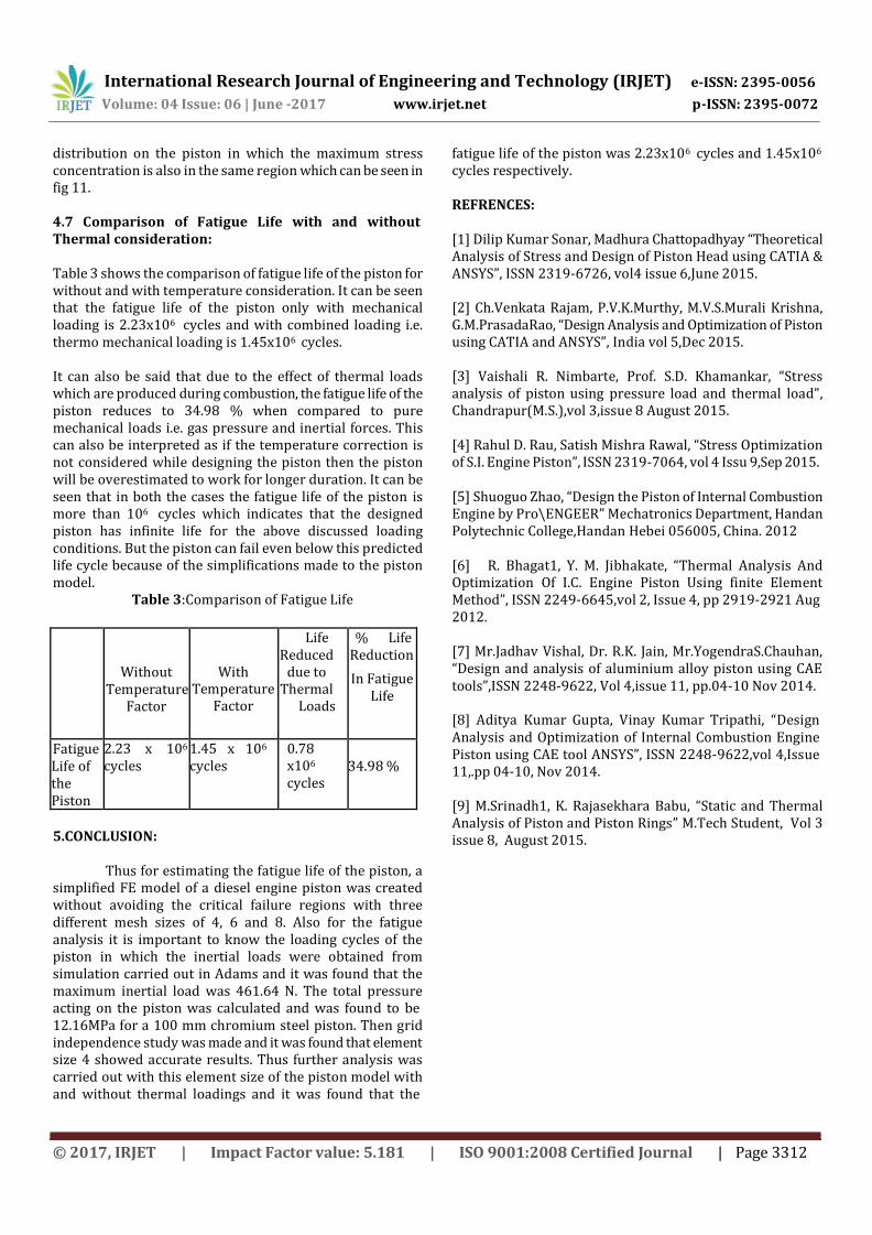
Fig 11: Fatigue Life of the Piston with Temperature Correction Factor
In order to estimate the vulnerable spot for fatigue in the piston, the result file generated in Fesafe was viewed in Ansys. Figure shows the critical spots in which the crack will initiate or will fail due to fatigue. It can be seen that the maximum life cycle of the piston is 7.699 i.e. Antilog (7.699) = 5x10⁷ cycles which is represented by the red region. The blue spots indicate the low cycle fatigue region which can be seen in the inner top surface region of the piston and the minimum life cycle in this area is 6.162 i.e. Antilog (6.162) = 1.45x10⁶ cycles. It can be validated by considering the stress
International Research Journal of Engineering and Technology (IRJET) e-ISSN: 2395-0056
p-ISSN: 2395-0072 Volume: 04 Issue: 06 | June -2017 www.irjet.net
© 2017, IRJET | Impact Factor value: 5.181 | ISO 9001:2008 Certified Journal | Page 3312
distribution on the piston in which the maximum stress concentration is also in the same region which can be seen in fig 11.
4.7 Comparison of Fatigue Life with and without Thermal consideration:
Table 3 shows the comparison of fatigue life of the piston for without and with temperature consideration. It can be seen that the fatigue life of the piston only with mechanical loading is 2.23x10⁶ cycles and with combined loading i.e. thermo mechanical loading is 1.45x10⁶ cycles.
It can also be said that due to the effect of thermal loads which are produced during combustion, the fatigue life of the piston reduces to 34.98 % when compared to pure mechanical loads i.e. gas pressure and inertial forces. This can also be interpreted as if the temperature correction is not considered while designing the piston then the piston will be overestimated to work for longer duration. It can be seen that in both the cases the fatigue life of the piston is more than 106 cycles which indicates that the designed piston has infinite life for the above discussed loading conditions. But the piston can fail even below this predicted life cycle because of the simplifications made to the piston model.
Table 3:Comparison of Fatigue Life
Without
Temperature Factor
With
Temperature Factor
Life Reduced
due to Thermal
Loads
% Life Reduction
In Fatigue Life
Fatigue Life of the Piston
2.23 x 10⁶
cycles 1.45 x 10⁶
cycles 0.78 x10⁶
cycles
34.98 %
5.CONCLUSION:
Thus for estimating the fatigue life of the piston, a
simplified FE model of a diesel engine piston was created without avoiding the critical failure regions with three different mesh sizes of 4, 6 and 8. Also for the fatigue analysis it is important to know the loading cycles of the piston in which the inertial loads were obtained from simulation carried out in Adams and it was found that the maximum inertial load was 461.64 N. The total pressure acting on the piston was calculated and was found to be 12.16MPa for a 100 mm chromium steel piston. Then grid independence study was made and it was found that element size 4 showed accurate results. Thus further analysis was carried out with this element size of the piston model with and without thermal loadings and it was found that the
fatigue life of the piston was 2.23x10⁶ cycles and 1.45x10⁶
cycles respectively. REFRENCES: [1] Dilip Kumar Sonar, Madhura Chattopadhyay “Theoretical Analysis of Stress and Design of Piston Head using CATIA & ANSYS”, ISSN 2319-6726, vol4 issue 6,June 2015. [2] Ch.Venkata Rajam, P.V.K.Murthy, M.V.S.Murali Krishna, G.M.PrasadaRao, “Design Analysis and Optimization of Piston using CATIA and ANSYS”, India vol 5,Dec 2015. [3] Vaishali R. Nimbarte, Prof. S.D. Khamankar, “Stress analysis of piston using pressure load and thermal load”, Chandrapur(M.S.),vol 3,issue 8 August 2015. [4] Rahul D. Rau, Satish Mishra Rawal, “Stress Optimization of S.I. Engine Piston”, ISSN 2319-7064, vol 4 Issu 9,Sep 2015. [5] Shuoguo Zhao, “Design the Piston of Internal Combustion Engine by Pro\ENGEER” Mechatronics Department, Handan Polytechnic College,Handan Hebei 056005, China. 2012 [6] R. Bhagat1, Y. M. Jibhakate, “Thermal Analysis And Optimization Of I.C. Engine Piston Using finite Element Method”, ISSN 2249-6645,vol 2, Issue 4, pp 2919-2921 Aug 2012. [7] Mr.Jadhav Vishal, Dr. R.K. Jain, Mr.YogendraS.Chauhan, “Design and analysis of aluminium alloy piston using CAE tools”,ISSN 2248-9622, Vol 4,issue 11, pp.04-10 Nov 2014. [8] Aditya Kumar Gupta, Vinay Kumar Tripathi, “Design Analysis and Optimization of Internal Combustion Engine Piston using CAE tool ANSYS”, ISSN 2248-9622,vol 4,Issue 11,.pp 04-10, Nov 2014. [9] M.Srinadh1, K. Rajasekhara Babu, “Static and Thermal Analysis of Piston and Piston Rings” M.Tech Student, Vol 3 issue 8, August 2015.