design and fabrication of pedal operator recipocating water pump
TRANSCRIPT

IOSR Journal of Mechanical and Civil Engineering (IOSR-JMCE)
e-ISSN 2278-1684 p-ISSN 2320-334X
PP 64-83
wwwiosrjournalsorg
International Conference on RECENT TRENDS IN ENGINEERING AND MANAGEMENT 64 | Page
Indra Ganesan College of Engineering
DESIGN AND FABRICATION OF PEDAL OPERATOR
RECIPOCATING WATER PUMP
Sermaraj M MARCET Dept Mechanical
Abstract A Water system includes a reciprocating pump operated by pedaling power The pump set and
includes a housing in which a foot pedal and drive shaft rotate an eccentric pin rotating with the drive shaft
moves a connecting rod which in turn causes push rod to move linearly The pushrod extends into a pressure
tight chamber formed above the rising main A pump rod connected to the push-rod extends to the conventional
plunger through verified motion
Pumps are a common means of lifting water from a clean ground water source to a useful point of
access but all pumps have moving parts and are therefore destined to break proper selection of a pump will
reduce undesirable downtime and will empower the local community to manage their water source
Here we use the foot pedal pump powered by our legs instead of arms to lift the water from a depth
range of seven meters Throughout history human energy has generally been applied through the use of the
arms hands and back With minor exceptions it was only with the invention of the sliding-seat rowing shell
and particularly of the bicycle that legs also began to be considered as a normal means of developing power
from human muscles
A person can generate four times more (14 horse power (hp)) by pedaling than by hand ndashcranking At
the rate of 14hp continuous pedaling can be done for only short periods about 10 minutes However pedaling
at half this power (18 hp) can be sustained for around 60 minutes
The main use of pedal power today is still for bicycling at least in the high- power range (75 watts and above of
mechanical power) In the lower-power range there are a number of use of pedal power for agriculture
construction water pumping and electrical generation that seem to be potentially advantages at least when
electrical or internal-combustion engine power is unavailable or very expensive
I LINE DIAGRAM
II OVER VIEW OF HUMAN POWER MACHINE Doubts on progress and technology Home About All articles Obsolete
technology Ecotech myths Low-tech solutions No Tech Magazine
11 posts categorized Human powered machines
IOSR Journal of Mechanical and Civil Engineering (IOSR-JMCE)
e-ISSN 2278-1684 p-ISSN 2320-334X
PP 64-83
wwwiosrjournalsorg
International Conference on RECENT TRENDS IN ENGINEERING AND MANAGEMENT 65 | Page
Indra Ganesan College of Engineering
How to downsize a transport network the Chinese wheelbarrow
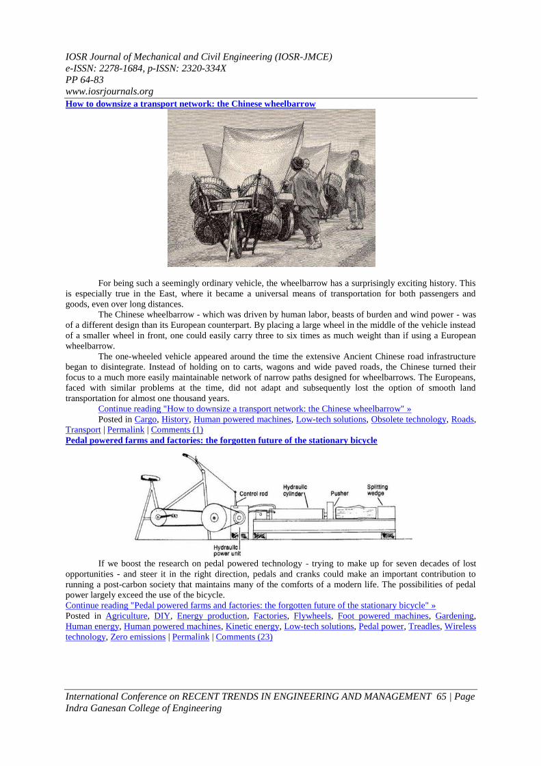
For being such a seemingly ordinary vehicle the wheelbarrow has a surprisingly exciting history This
is especially true in the East where it became a universal means of transportation for both passengers and
goods even over long distances
The Chinese wheelbarrow - which was driven by human labor beasts of burden and wind power - was
of a different design than its European counterpart By placing a large wheel in the middle of the vehicle instead
of a smaller wheel in front one could easily carry three to six times as much weight than if using a European
wheelbarrow
The one-wheeled vehicle appeared around the time the extensive Ancient Chinese road infrastructure
began to disintegrate Instead of holding on to carts wagons and wide paved roads the Chinese turned their
focus to a much more easily maintainable network of narrow paths designed for wheelbarrows The Europeans
faced with similar problems at the time did not adapt and subsequently lost the option of smooth land
transportation for almost one thousand years
Continue reading How to downsize a transport network the Chinese wheelbarrow raquo
Posted in Cargo History Human powered machines Low-tech solutions Obsolete technology Roads
Transport | Permalink | Comments (1)
Pedal powered farms and factories the forgotten future of the stationary bicycle
If we boost the research on pedal powered technology - trying to make up for seven decades of lost
opportunities - and steer it in the right direction pedals and cranks could make an important contribution to
running a post-carbon society that maintains many of the comforts of a modern life The possibilities of pedal
power largely exceed the use of the bicycle
Continue reading Pedal powered farms and factories the forgotten future of the stationary bicycle raquo
Posted in Agriculture DIY Energy production Factories Flywheels Foot powered machines Gardening
Human energy Human powered machines Kinetic energy Low-tech solutions Pedal power Treadles Wireless
technology Zero emissions | Permalink | Comments (23)
IOSR Journal of Mechanical and Civil Engineering (IOSR-JMCE)
e-ISSN 2278-1684 p-ISSN 2320-334X
PP 64-83
wwwiosrjournalsorg
International Conference on RECENT TRENDS IN ENGINEERING AND MANAGEMENT 66 | Page
Indra Ganesan College of Engineering
Bike powered electricity generators are not sustainable
Pedalling a modern stationary bicycle to produce electricity might be a great work-out but in many
cases it is not sustainable While humans are rather inefficient engines converting food into work this is not the
problem we want to address here people have to move in order to stay healthy so we might as well use that
energy to operate machinery The trouble is that the present approach to pedal power results in highly inefficient
machines
Continue reading Bike powered electricity generators are not sustainable raquo
Posted in Batteries Bicycles DIY Ecotech Embodied energy Energy Energy production Flywheels Foot
powered machines Human energy Human powered machines Kinetic energy Pedal power | Permalink |
Comments (13)
The short history of early pedal powered machines
Ever since the arrival of fossil fuels and electricity human powered tools and machines have been
viewed as an obsolete technology This makes it easy to forget that there has been a great deal of progress in
their design largely improving their productivity
The most efficient mechanism to harvest human energy appeared in the late 19th century pedaling Stationary
pedal powered machines went through a boom at the turn of the 20th century but the arrival of cheap electricity
and fossil fuels abruptly stopped all further development
Continue reading The short history of early pedal powered machines raquo
Posted in Drilling tools Energy Foot powered machines History Human energy Human powered machines
Kinetic energy Obsolete technology Pedal power Tools Treadles Wireless technology Zero emissions |
Permalink | Comments (0)
IOSR Journal of Mechanical and Civil Engineering (IOSR-JMCE)
e-ISSN 2278-1684 p-ISSN 2320-334X
PP 64-83
wwwiosrjournalsorg
International Conference on RECENT TRENDS IN ENGINEERING AND MANAGEMENT 67 | Page
Indra Ganesan College of Engineering
Hand powered drilling tools and machines
Hand-powered devices have been used for millennia but during the last quarter of the 19th century a
radically improved generation of tools appeared taking advantage of modern mass production machinery and
processes (like interchangeable parts) and an increased availability in superior material (metal instead of wood)
One of the outcomes included an array of new drilling machines but their heydays were over fast
These human-powered tools were not only a vast improvement over those that came before them they also had
many advantages in comparison to the power drills that we use today
A 1922 breast drill (picture credit)
Continue reading Hand powered drilling tools and machines raquo
Posted in Drilling tools Drills Hand powered machines Hand tools History Human energy Human powered
machines Kinetic energy Low-tech solutions Obsolete technology Tools Zero emissions | Permalink |
Comments (28)
November 24 2010
The sky is the limit human powered cranes and lifting devices
From the earliest civilisations right up to the start of the Industrial Revolution humans used sheer
muscle power organization skills and ingenious mechanics to lift weights that would be impossible to handle by
most power cranes in operation today
Continue reading The sky is the limit human powered cranes and lifting devices raquo
Posted in Architecture Cargo Craftsmanship Cranes amp lifting devices History Human powered machines
Knots Low-tech solutions Obsolete technology Ropes Speed Towers Tread wheels Wire ropes Zero
emissions | Permalink | Comments (12)
IOSR Journal of Mechanical and Civil Engineering (IOSR-JMCE)
e-ISSN 2278-1684 p-ISSN 2320-334X
PP 64-83
wwwiosrjournalsorg
International Conference on RECENT TRENDS IN ENGINEERING AND MANAGEMENT 68 | Page
Indra Ganesan College of Engineering
Cars out of the way
Some readers have observed that we havent paid any attention to one of the most low-tech innovations
ever - the humble bicycle We noted the sex-appeal of pedal power (and this concerns both men and women)
but thats about it So since you asked for it here is our concise but clear point of view on these human powered
two-wheelers
III OVER VIEW OF HAND OPERATED PUMP
Hand pump
Hand pumps are manually operated pumps they use human power and mechanical advantage to move fluids or
air from one place to another They are widely used in every country in the world for a variety of industrial
marine irrigation and leisure activities There are many different types of hand pump available mainly
operating on a piston diaphragm or rotary vane principle with a check valve on the entry and exit ports to the
chamber operating in opposing directions Most hand pumps have plungers or reciprocating pistons and are
positive displacement[1]
Types Suction and lift hand pumps
Suction and lift are important considerations when pumping fluids Suction is the vertical distance
between the fluid to be pumped and the center of the pump while lift is the vertical distance between the pump
and the delivery point The depth from which a hand pump will suck is limited by atmospheric pressure to an
operating depth of less than 7 meters The height to which a hand pump will lift is governed by the ability of the
pump and the operator to lift the weight in the delivery pipe Thus the same pump and operator will be able to
achieve a greater lift with a smaller diameter pipe than they could with a larger diameter pipe
Siphons
Water will always try to find its lowest level Using this principle very simple pumps with plastic or
rubber bulb with flap valve at each end are used for emptying fuel or water cans into tanks Once the bulb is full
the fluid will flow without further effort from the higher to the lower container Many hand pumps will allow
the passage of fluid through them in the direction of flow and diaphragm pumps are particularly good at this
IOSR Journal of Mechanical and Civil Engineering (IOSR-JMCE)
e-ISSN 2278-1684 p-ISSN 2320-334X
PP 64-83
wwwiosrjournalsorg
International Conference on RECENT TRENDS IN ENGINEERING AND MANAGEMENT 69 | Page
Indra Ganesan College of Engineering
Thus where the levels are correct large volumes of liquid such as swimming pools can be emptied with very
little effort and no expensive energy use
Direct action
Direct action hand pumps have a pumping rod that is moved up and down directly by the user
discharging water Direct action hand pumps are easy to install and maintain but are limited to the maximum
column of water a person can physically lift of up to 15 m
Deep wells
Deep well hand pumps are used for high lifts of more than 15 m The weight of the column of water is
too great to be lifted directly and some form of mechanical advantage system such as a lever or flywheel is used
High lift pumps need to be stronger and sturdier to cope with the extra stresses The installation maintenance
and repair of deep well hand pumps is more complicated than with other hand pumps
A deep well hand pump theoretically has no limit to which it can extract water In practice the depth is limited
by the physical power a human being can exert in lifting the column of water which is around 80 m
Diaphragm
Diaphragm pumps have the advantage that they pump relatively lightly due to the lack of pulling rods
and are corrosion resistant Their disadvantage is that they need a specific length of tubing and high quality
rubber diaphragms which are costly and are relatively inefficient due to the extra work needed to deform the
diaphragm
Rubber diaphragms will eventually leak and need to be replaced Because this is usually complicated
and costly diaphragm pumps operating in poor rural areas are often abandoned once the diaphragm wears out
Progressive cavity
Progressive cavity pumps consist of a single helix rotor inserted into a double helix stator As the rotor
is turned the voids in the stator are screwed upwards along the axis of rotation Progressive cavity pumps can
have complicated gearing mechanisms and are difficult for local pump technicians to maintain and repair
A rope and washer pump is a type of progressive cavity hand pump
Range of lift
The range of lift of different types of hand pumps is given below[2]
Type Range
Suction pumps 0 ndash 7 meters
Low lift pumps 0 ndash 15 meters
Direct action pumps 0 ndash 15 meters
Intermediate lift pumps 0 ndash 25 meters
High lift pumps 0 ndash 45 meters or more
Hand pumps and access to clean water
In November 2002 the United Nations Committee on Economic Social and Cultural Rights asserted
that access to clean safe water goes beyond the classification of water as an economic commodity The
committee stressed the fundamental right of sufficient access to clean water for both domestic and personal use
ldquoThe human right to water is indispensable for leading a life in human dignityrdquo [3]
With this in mind
manufacturers of water pumps like those produced by GOAZ Development in Malaysia have a wide range of
potential customers governments non- governmental organizations womenrsquos groups community groups and
other organizations of various types interested to developing access to groundwater[2]
However there is controversy surrounding the sustainability of hand pumps and the long-term gains
from investing in them A number of difficulties are associated with the use of hand pumps these include cost
hygiene maintenance and availability of spare parts responsibility of upkeep community involvement
technology organization and education Hand pumps battered by intense use and conditions in rural areas have
often fallen apart In addition unobtainable spare parts impede maintenance
IOSR Journal of Mechanical and Civil Engineering (IOSR-JMCE)
e-ISSN 2278-1684 p-ISSN 2320-334X
PP 64-83
wwwiosrjournalsorg
International Conference on RECENT TRENDS IN ENGINEERING AND MANAGEMENT 70 | Page
Indra Ganesan College of Engineering
IV COMMON USED PUMP IN DOMESTIC amp INDUSTRIES CENTRIFUGAL PUMP
A centrifugal pump is one of simplest rotating equipment in any process plant Centrifugal pump may
be single stage (one impeller) or multistage (multiple impeller) and can be horizontal split or barrel type or
vertical type Higher the deliverydischarge pressure required more the number of impellers will be needed In
centrifugal pump energy is imparted to the fluid in form of velocity or kinetic energy and which is then
converted into pressure energy of the fluid that is being pumped This form of energy change occurs by virtue of
two main parts of the pump First the rotating part impeller imparts kinetic energy to the fluids and then the
stationary part diffuser or volute converts kinetic energy of the fluid into pressure energy All the forms of
energy involved in a fluid flow system are expressed in terms of Head or height of liquid column discharged by
the pumps
Axial Flow centrifugal pump Mix flow Centrifugal pump
Principle The process liquid enters through the suction nozzle of the pump and then into eye (center) of the
impeller When the impeller rotates it spins the liquid in the space between the vanes and throws outward in the
volute and provides centrifugal acceleration As the liquid leaves the eye of the impeller a low pressure area is
created causing more liquid to flow at the inlet Because the impeller bladesvanes are of curve shape the liquid
is pushed in a tangential and radial direction by the centrifugal force The energy created by the centrifugal force
is kinetic energy and proportional to the velocity at the edge or vane tip of the impeller The higher the RPM of
the impeller or bigger the size of the impeller higher will be the velocity of the liquid and greater kinetic energy
will be imparted to the liquid This kinetic energy of the liquid leaving the impeller is then harnessed by creating
a resistance to the flow
The pump volute or diffuser creates the first resistance and then in the discharge nozzle where it gets
further de-accelerated and the kinetic energy is converted into pressure energy according to Bernoullirsquos
principle Therefore the head (pressure in terms of height of liquid column) developed shall be approximately
equal to the kinetic energy imparted at the periphery of the impeller
In axial flow pumps the principal of working is different as volute and diffusers are not there so Kinetic energy
imparted by impeller gets converted partially into pressure and partially it remains in same form
Pump curves related to the flow rate and pressure (head) developed by the pump at different impeller sizes and
RPM The centrifugal pump operation should confirm to the pump curves supplied by the manufacturer
IOSR Journal of Mechanical and Civil Engineering (IOSR-JMCE)
e-ISSN 2278-1684 p-ISSN 2320-334X
PP 64-83
wwwiosrjournalsorg
International Conference on RECENT TRENDS IN ENGINEERING AND MANAGEMENT 71 | Page
Indra Ganesan College of Engineering
Construction of Centrifugal Pump
Generally a single stage centrifugal pump consists of the following main parts
-A casing with volute
-An impeller (closed vane or open vane)
-A shaft
-A gland housing with gland packing or Mechanical seal assembly
-Anti friction bearings
-Lantern rings
But in multistage centrifugal pumps there are much more components listed as below
-Casing (split horizontally or barrel type)
-Shaft with keys
-Impellers for all stages
-Diffuser diaphragms For all stages
-Shaft sleeves or Impeller sleeves
-Impeller neck rings
-Wearing rings
-Throttle bush or Throat bush
-Diffuser bush
-Drive end (DE) and Non Drive end (NDE) bearing housing
-Bearings thrust and journals
-Oil seal
-Mechanical seal assemblies
-Oil labyrinths
-Anti rotation devices
-Lip seals
-Balancing device with corresponding bush
- Coupling hub etc
Sketch showing the functioning of Diffusers in Centrifugal pumps
A barrel type multi stage pump
IOSR Journal of Mechanical and Civil Engineering (IOSR-JMCE)
e-ISSN 2278-1684 p-ISSN 2320-334X
PP 64-83
wwwiosrjournalsorg
International Conference on RECENT TRENDS IN ENGINEERING AND MANAGEMENT 72 | Page
Indra Ganesan College of Engineering
Pump casings with single volute and double volute
Shaft SleeveImpeller sleeve
These are used in single stage pumps Impeller and sealing gland are not directly mounted on shaft A
sleeve is fitted between the bore of the impeller and OD of the shaft and keyed with the shaft ie impeller rotate
with the sleeve along with the shaft The wearable part in this type of assembly is the sleeve which is far less
expensive than the shaft The function of the impeller sleeves is to protect the shaft from wear and coming in
contact with the pumping fluid
Wear ring Casing ring
Wearing ring provide easy and economically renewable relative movement joint between the impeller
and the casing and to protect the damage of impeller or casing in that area OEM generally recommends the
clearances between the casing wear ring and impeller wear rings and if these clearances exceeds pump
efficiency will be lowered and abnormal vibration increase will be some of the consequences
Impeller
This is the main rotating parts of the pump that imparts the centrifugal acceleration to the fluid
Impellers may be classified in many ways For example
-According to the direction of flow in reference to the axis of rotation of the shaft
i) Axial flow
ii) Radial flow
iii) Mixed flow
-According on suction type
i) Single suction
ii) Double suction
-According to mechanical construction of vanes
i) Closed vane type
Impeller wear
ring
Casing wear ring
Balancing hole
IOSR Journal of Mechanical and Civil Engineering (IOSR-JMCE)
e-ISSN 2278-1684 p-ISSN 2320-334X
PP 64-83
wwwiosrjournalsorg
International Conference on RECENT TRENDS IN ENGINEERING AND MANAGEMENT 73 | Page
Indra Ganesan College of Engineering
ii) Open vane type
iii) Semi open type
Open vane Impeller Semi open Impeller Closed vane impeller
Gland HousingStuffing Box and shaft sealing
To seal the leakage of fluid from where the shaft penetrates out the pump casing a gland packing
assembly or Mechanical seal assembly is provided and this assembly is fitted in the Gland housing Stuffing
box provided in the pump housing Specially made asbestosglass fiber filled Teflon rings are used for sealing
which is mounted between the stuffing box housing and shaft sleeve Gland packing is very economical to use
but this requires renewal at fix interval Also gland packing do not gives zero leakage assembly by any mean
For cooling of gland ropes small amount of leakage is mandatory to maintain For non toxic non critical
services gland packing is used in industrial pumps but mechanical seal assembly are used for all hazardous
services
Throttle Bush throat bushing
Throttle bush is a stationary device which forms a restrictive close clearance around the shaft in the
pump casing just in front of gland housing This helps in reducing the fluid flow load on mechanical seals and
also helps in maintaining the flushing fluid pressure in the gland boxes
Lantern ring
Basically lantern ring are provided in the stuffing box in case of gland packing rings sealing system to
give a recess and to cool the gland packing ringselements with the pump fluid It is installed between or in the
middle of the gland packing elements and a cooling line is connected just above the lantern ring from the pump
casing
Bearing Housing
The bearing housings are equally critical parts and they encloses the bearings in the drive end and non
drive end of the pumps These housings keeps the shaft or rotor assembly in correct alignment with the
stationary parts under radial and axial loads The bearing housing are built with required oil reservoir for bearing
lubrication and water jacket for circulating cooling water for bearing cooling Now a dayrsquos bearing jackets are
avoided as studies shows that oil cooling is more effective than jacket cooling of bearing housings
IOSR Journal of Mechanical and Civil Engineering (IOSR-JMCE)
e-ISSN 2278-1684 p-ISSN 2320-334X
PP 64-83
wwwiosrjournalsorg
International Conference on RECENT TRENDS IN ENGINEERING AND MANAGEMENT 74 | Page
Indra Ganesan College of Engineering
Axial thrust of a Centrifugal pump and its balancing
In centrifugal pumps the impeller is surrounded by fluid at different pressure at different locations in
the casing This variation in pressure on the surface of the impeller during running condition creates axial
hydraulic thrust which is the summation of unbalanced impeller forces in the axial direction
In case of multistage pump if all the impeller suction faces are in the same direction the total
theoretical axial thrust acting towards the suction end of the pump will be sum of the individual impellerrsquos thrust
in that direction There are various methods which can be employed to counter balance this hydraulic axial
thrust in multistage pumps Some times more than one technique is used to take advantages of these methods
These are as below
-Provision of balance drumbalance stepped drum
-Provision of balancing disc
-Provision of combination balancing disc-drum
-Provision of impeller back side wearing ring and balancing hole
-Provision of double suction impeller
-Provision of fixing of impellers in back to back configuration
In single stage pumps additional balancing devices are seldom used Big single stage pumps are
generally designed with double suction impellers and smaller pumps are provided with provision of balancing
holes back side wear rings etc The residual thrust is taken care by the thrust bearings
Multistage pumps are generally built with single suction impellers however some manufacturerrsquos uses
double suction impeller in first stage of the pump assembly Single suction impellers may be mounted on shaft
and each impeller suction eye facing in the same direction and its stages are arranged one after another in an
ascending order of pressure and the total axial thrust is balanced by hydraulic balancing devices But in this type
of assemblies the resultant axial thrust is generally very high and a big size balancing device is needed along
with suitably big thrust bearing However this type of assemblies is easy to make and require lesser grades of
skill in maintenance
More efficient more balance multistage pumps are made with impellers fixed in tandem up to middle
stage and than in reverse direction again in tandem up to final stage Combination of two tandems in back to
back neutralizes the axial thrust and resultant axial thrust is minimum and can be taken by the nominal size
thrust bearing These types of assemblies are requiring exact calculations and skilled group to assemble
Manufacturer makes arrangement of interstage connections in such a way that no out side lines are required to
be connected Impeller dimensions and weights of each stage is very critical for such type of assemblies and
casing designs become very difficult
Balancing Devices
Balancing device is an additional part which is fixed in the assembly to neutralize the axial thrust while
in operation In this system a balancing drum is attached with the shaft to rotate with the shaft at the back of the
last stage impeller and there is a balancing chamber which is connected to the pump suction The radial
clearance between stationary balancing bush and rotary balancing drum is very critical
One of the latest developments in this category is the stepped drum design This type of design is
employed on BFW pumps of super thermal power plants where multi stage pumps develop pressures of 200
kgcm2
IOSR Journal of Mechanical and Civil Engineering (IOSR-JMCE)
e-ISSN 2278-1684 p-ISSN 2320-334X
PP 64-83
wwwiosrjournalsorg
International Conference on RECENT TRENDS IN ENGINEERING AND MANAGEMENT 75 | Page
Indra Ganesan College of Engineering
Balancing Drum
Two forces acting on the balancing drum are
i) Towards the discharge end which is discharge pressure multiplied by the front balancing area=F1
ii) Towards the suction end which is back pressure or pressure in the balancing chamber multiplied by back
balancing area=F2
As the cross section area on two sides is equal but the pressure on impeller side is high therefore force F1gtF2
Therefore the axial thrust generated in the multistage single suction impeller assembly is counter balanced by
the additional balancing device
Balancing Disc
Axial Clearance
Connected to suction
side of pump
Radial
Clearance Balance drum
bush Balancing
drum
Connected to
suction side of
pump
Radial Clearances
in two steps
Connected to suction
side of pump
Stepped Drum
Axial Clearance
IOSR Journal of Mechanical and Civil Engineering (IOSR-JMCE)
e-ISSN 2278-1684 p-ISSN 2320-334X
PP 64-83
wwwiosrjournalsorg
International Conference on RECENT TRENDS IN ENGINEERING AND MANAGEMENT 76 | Page
Indra Ganesan College of Engineering
Balancing Disc
The functioning of the balancing disc is same as that of balancing drum This is a compact device as
compared to balancing drum and is employed for comparatively smaller high pressure pumps In this device a
balancing disc is allowed to rotate with the shaft and this disc is separated from the balancing disc head which
is fixed to the pump casing with a small axial clearance The back of the balancing disc is subject to the
balancing chamber backpressure and the disc face is subjected to the discharge pressure of the pump There is a
continuous leakage through the axial clearance between the disc and the disc head and fluid flows into the
balancing chamber If the axial thrust of the impeller at any moment exceeds the thrust on the disc the disc
assembly moved towards the disc head reducing the axial clearance between the disc and disc head and reduced
the leakage which in turn lowers the back pressure in the balancing chamber This lowering of pressure
automatically increase the pressure difference acting on the disc and move it away from the disc head
increasing the clearance until an equilibrium condition is reached
Combination of Balancing drum and Balancing disc
Material of Construction of Pump Components
Except the mechanical seal mating faces none of the pump components comes in direct contact with
each other however the service of the pump in which it has to perform dictates the material of construction of
the pump components The following criteria should be considered important in the selection of MOC of the
pump components
i) Corrosion Resistance
ii) Abrasive Wear Resistance
iii) Cavitations Resistance
iv) Strength
v) Tensile Strength
vi) Endurance Limits
vii) Fatigue Strength
viii) Cost
ix) Maintenance
All components of pump may not be required to fulfill all above mentioned criteria Depending upon
the function it has to perform different components require meeting some or all the above criteria to be found
suitable for selection eg MOC of an impeller is required to meet requirements of corrosion resistance abrasive
wear resistance cavitations resistance shall be suitable for casting and machining properties but for shaft of
pump it is required to meet only endurance limits tensile strength hardness corrosion resistance and machining
properties
For pump casing material of construction shall have properties equivalent to impeller MOC
The most widely used materials in pump components are cast iron bronze cast steel austenite steel
and marten site steel and different grades of plastics selected according to application During selection of
material cost and availability should also be considered Unnecessary costly material should not be used unless
it is required for the service
Future maintenance shall also be a point to consider for the selection of the material of construction of
the components Some of the components are required to be replaced during the normal operation after normal
Axial
Clearance
Radial
clearance
Connected to
suction side of
pump
Combined Disc
Drum
IOSR Journal of Mechanical and Civil Engineering (IOSR-JMCE)
e-ISSN 2278-1684 p-ISSN 2320-334X
PP 64-83
wwwiosrjournalsorg
International Conference on RECENT TRENDS IN ENGINEERING AND MANAGEMENT 77 | Page
Indra Ganesan College of Engineering
wear amp tear however major components are designed to perform for the service life but maintenance of all parts
shall be considered at the time of selection
Mechanical seal
Mechanical seals are the positive sealing devices used for the sealing of fluids at the shaft end of the
pumps Now days in petrochemical industries and refineries mechanical seals as per API 682 are only approved
seal designs which can be used on pumps Very stringent requirement of API code have forced seal designers
and manufactures to innovate newer quality products to enhance the seal efficiencies
The conventional stuffing box design with gland packing rings is impractical for many service
conditions In the ordinary stuffing box the sealing between the rotating shaft and the stationary gland casing
(where the shaft penetrates the casing) is accomplished by means of gland packing ring elements held tightly in
the stuffing box around the shaft sleeve and gland follower After certain time of operation the gland packing
leakages starts due to nominal wearing Gland follower is further tightened to stop the leakages
In this way the shaftsleeve and gland pickings get worn out and the renewal of the parts has to be done
for further service In gland packing as the sealing is achieved by tightening of the packing rings directly
between the rotating and stationary parts lot of energy or power is lost
To eliminate this problem and where minimum leakages is required due to expensive or hazardous
chemicals Mechanical seal is required to be installed In big cooling water pumps the replacement of gland
packing with mechanical seals gives benefit of power up to 7
The mechanical seal is a device where two mating surfaces (one is rotating with the shaft and another is
stationary) are located in a plane perpendicular to the shaft axis The two mating surfaces are highly polished
and of dissimilar material of which one is keyed to the shaft shaft sleeve to rotate with the shaft and another
one is fixed in the seal chamberhousing which seal the liquid The basic objective of the mechanical seal
assembly is to prevent leakages of fluid Other than these two main parts there are number of elastomers to
prevent path of leakages through sleeve sealing faces etc springs and spring retainer to exert axial force
gaskets gland plates sleeve etc The fundamental principle of mechanical seal operation is the development and
maintain of liquid film between the two mating surfaces This microscopic film of liquids acts as a cushion for
the seal faces preventing and minimizing wear and dissipation of heat generated due to rubbing action The
rotating face may be of carbon graphite tungsten carbide silicon carbide and the stationery face may be of one
of the above but if the stationary face is carbon graphite then the rotating face should be of dissimilar material
of silicon carbidetungsten carbide and vice versa ie if the stationary face is soft then the rotating face should
be hard or vice versa
This selection of material varies from manufacturer to manufacturer and both have some advantage
and disadvantages
A single spring dual direction seal
Some important maintenance tips during installation of mechanical seal and for its better life are as
below
a) Stuffing box face
The stuffing box face should be square or perpendicular to the shaft axis otherwise resulting in wrong fixing of
stationary element of the seal in gland plate This will results in seal wobble and not having full face contact in
running and rotary head may get elliptical movement against stationary
b) Concentricity of the stuffing box The stuffing box should be concentric to the shaft axis within 008mm
c) Lateral or axial movement of shaft (end play) The mechanical seal cannot function satisfactorily with great
amount of end play If the hydraulic condition changes which happens frequently and if the hydraulic axial
balance is not effective the shaft may float and leading to seal troubles The total amount of shaftrotor end play
should be within 008mm ~ 02mm
IOSR Journal of Mechanical and Civil Engineering (IOSR-JMCE)
e-ISSN 2278-1684 p-ISSN 2320-334X
PP 64-83
wwwiosrjournalsorg
International Conference on RECENT TRENDS IN ENGINEERING AND MANAGEMENT 78 | Page
Indra Ganesan College of Engineering
d) Radial movement of shaft (whip or deflection) Excessive whip or deflection can lead to seal failure and poor
sealing performance The radial movement of shaft should be 005mm ~ 008mm
e) Alignment of driver Driver alignment is by far the most frequent encountered pump problem The poor
alignment causes axial and radial vibrations resulting in failure of seal
21Characteristic of Centrifugal pumps
The key performance parameters of centrifugal pumps are capacity head BEP (Best Efficiency Point)
and specific speed The pump curves provide the operating window within which these parameters can be varied
for satisfactorily pump operation
End user supplies the data of the requirements and manufacturer makes the pump to full fill the
requirement of the end user Basic requirements and manufactured product performances are plotted on the
graph and the intersecting points are known as rated capacity This graph of plots of performance of pump is
known as performance curves or characteristic curves of the pump
Inability to deliver the desired flow and head is one of the most common conditions for making a pump
out of service Many times when the pumps are opened with low or no delivery conditions but on opening no
fault is observed
In such conditions there are three type of problem which mostly encountered are
-Design error
-Poor process operation
-Poor maintenance practices
These problems can be identified when the current performance of the pump is judged against the
characteristics of the pump The deteriorated parameter shall be further analyzed and then the problem shall be
settled
The performance of any pumping system can be marked in terms of its capacity or flow (Q) and
pressure (head)The variation curves of capacity versus pressure of a particular pump are known as pump
performance curve
The plot starts at zero flow and the head at this point corresponds to the shut off head of the specific
pump The curve then decreases to a point where the flow is maximum and the head is minimum This point is
called run-out point The pump curve is relatively flat and the head decreases gradually as the flow increases
Beyond the run-out point the pump cannot operate The pumprsquos range of operation is from the shut-off head
point to the run-out point
V RECIPROCATING PUMP
IOSR Journal of Mechanical and Civil Engineering (IOSR-JMCE)
e-ISSN 2278-1684 p-ISSN 2320-334X
PP 64-83
wwwiosrjournalsorg
International Conference on RECENT TRENDS IN ENGINEERING AND MANAGEMENT 79 | Page
Indra Ganesan College of Engineering
Reciprocating Pumps- classifications-construction and working of single acting and double acting
reciprocating pumps-plunger and piston pumps-discharge of a reciprocating pump-theoretical power required-
coefficient of discharge-slip-problems-negative slip-indicator diagram-separation-air vessel (functions and
working) Special pumps-jet pump-Turbine pump-Submersible pump
Reciprocating pumps These types of pump operate by using a reciprocating piston The liquid enters a pumping chamber via
an inlet valve and is pushed out via a outlet valve by the action of the piston or diaphragm
Reciprocating pumps are generally very efficient and are suitable for very high heads at low flows
This type of pump is self priming as it can draw liquid from a level below the suction flange even if the suction
pipe is not evacuated The pump delivers reliable discharge flows and is often used for metering duties
delivering accurate quantities of fluid
The reciprocating pump is not tolerant to solid particles and delivers a highly pulsed flow If a smooth
flow is required then the discharge flow system has to include additional features such as accumulators to
provide even flows
Reciprocating pumps designed for delivering high pressures must include methods for releasing
excessive fluid pressures The pumps should include for built in relief valves or relief valves should be
included in the fluid circuit which cannot be isolated from the pump This feature is not required for safety for
the air operated diaphragm valve
VI MAJOR COMPONETS OF PEDALOPERATED DRILLIING MACHINE
1 Piston
2 Cylinder
3 Rod
4 Water seal
5 pedal link
1 PISTON
Piston is used to pressure creating component It is made of steel It is reciprocating in side the
cylinder Very close tolerance is maintained with cylinder
1 Cylinder
Cylinder is used to reciprocate the cylinder with close tolerance Piston will develop the maximum
pressure Cylinder is made of mils steel
2 Rod
It is connect the piston and foot pedal It is also used push the piston according to the foot pedal action
Rod is used to connect the piston and foot pedal pump link The maximum pressure is achieved pumping lifting
height It will convert angularity motion to linear motion
IOSR Journal of Mechanical and Civil Engineering (IOSR-JMCE)
e-ISSN 2278-1684 p-ISSN 2320-334X
PP 64-83
wwwiosrjournalsorg
International Conference on RECENT TRENDS IN ENGINEERING AND MANAGEMENT 80 | Page
Indra Ganesan College of Engineering
3 Water seal
The primary seal consists of two rings (a primary and mating ring) that are lapped to a high degree of flatness
and then loaded against one another by means of a spring One of these rings will rotate in accordance with the
shaft of the pump and rub against the other ring creating a seal for the fluid The material composition of the
primary and mating rings varies depending on duty and life expectancy goals for the application
The secondary seal consists of molded rubber components which are held in place via an adhesive or
mechanical press These secondary sealing components form the seal between the rotating faces and the metallic
components (spring retainer ferrules and sleeve) used to load the faces and to allow the pump builder to install
the seal quickly and efficiently
4 Pedal link
This type link is used to connect the piston rod and foot step mechanism This link is very sturdy due it
will withstand cyclic load
VII DESIGN ASPECTS AND OPERATION PROPERTIES OF MILD STEEL
PHYSICAL PROPERTY
Density - 7860 Kgm3
Melting point - 1427c
Thermal conductivity - 63 W m K
CARBON CONTENT
Low Carbon (or) Mild steel - 015 to045 carbon
MECHANICAL PROPERTY
o Elasticity
o Ductility
o Toughness
o Weld ability
In our design screw type clamp Body of jig have a main part hence the calculations are concentrated on it
VIII DESIGN CALCULATIONS FOR PUMP To calculate the volume of the cylinder
Volume=Arealength
Area= (π4D2)
X L
D=Diameter of the piston
D=110mm
IOSR Journal of Mechanical and Civil Engineering (IOSR-JMCE)
e-ISSN 2278-1684 p-ISSN 2320-334X
PP 64-83
wwwiosrjournalsorg
International Conference on RECENT TRENDS IN ENGINEERING AND MANAGEMENT 81 | Page
Indra Ganesan College of Engineering
L=90mm
=85529m3
DESIGN FOR CYLINDER
The force exerted on in stroke can be expressed as
F = p π (d12 - d2
2) 4
Where
P = Initial pressure (Nmsup2)
d1 = full bore piston diameter (m)
d2 = piston rod diameter (m)
For Example
P = 1 bar (assumed)
π = 314
d1 = 011m
d2 = 0010m
F = p π (d12 - d2
2) 4
F = 1x105x314x (011
2 ndash 0010
2) 4
F = 1884955592x2275x10-3
4
F = 942 N
IX OPERATIONS INVOLVED o Turning (facing plain turning step turning threading etc)
o Facing (flat surface)
o Drilling
o Gas cutting (flat plate cylindrical rods)
o Shaping
o Welding
o Tapping
o Thread cutting
TURNING
Turning is the operation of reducing a cylindrical surface by removing material from the outside
diameter of a work piece It is done by rotating the work piece about the lathe axis and feeding the tool parallel
to the lathe axis Due to this operation screw rod and head are done by the turning operation to get the required
shape
FACING
Machining the end of the work piece to produce flat surface is called facing Due to this the plate can get
flat surface have done by the facing operation
DRILLING Drilling is the operation of producing cylindrical hole in work piece It is done by rotating the cutting
edge of the cutter known as drill bit In this Project the jig plates require holes for locating indexing plate and
screw rod drill bush assembly These holes are done by conventional vertical drilling machine
THREAD CUTTING
Thread cutting is the operation of forming external thread of required diameter of rod by using a
multipoint tool is called thread This process is used in screw clamp to done on the rod which is used for the
movement of the movable plate
IOSR Journal of Mechanical and Civil Engineering (IOSR-JMCE)
e-ISSN 2278-1684 p-ISSN 2320-334X
PP 64-83
wwwiosrjournalsorg
International Conference on RECENT TRENDS IN ENGINEERING AND MANAGEMENT 82 | Page
Indra Ganesan College of Engineering
FINE GRINDING
It is nothing but the grinding process which is done as smooth with fine grains This is done as the
each plate and base plate for good surface finish It is done by conventional grinding machine
GAS CUTTING
It is used to break are cut the plates In this project it is used to cut the raw materials such as plates
This done by gas cutting machine
SHAPING
Shaping operation is used to reduce the dimensions of the plates In this project the plates are in need of
shaping process It is done by shaping machine
WELDING
It is the process which is used to join two is more similar materials as well as dissimilar materials In
this project it is used to join the jig plate one to another This is done by arc welding machine
X WORKING PRINCIPLE
Pumps are a common means of lifting water from a clean ground water source to a useful point of
access but all pumps have moving parts and are therefore destined to break proper selection of a pump will
reduce undesirable downtime and will empower the local community to manage their water source
Here we use the foot pedal pump powered by our legs instead of arms to lift the water from a depth
range of seven meters Throughout history human energy has generally been applied through the use of the
arms hands and back With minor exceptions it was only with the invention of the sliding-seat rowing shell
and particularly of the bicycle that legs also began to be considered as a normal means of developing power
from human muscles
A person can generate four times more (14 horse power (hp)) by pedaling than by hand ndashcranking At
the rate of 14hp continuous pedaling can be done for only short periods about 10 minutes However pedaling
at half this power (18 hp) can be sustained for around 60 minutes
The main use of pedal power today is still for bicycling at least in the high- power range (75 watts and above of
mechanical power) In the lower-power range there are a number of use of pedal power for agriculture
construction water pumping and electrical generation that seem to be potentially advantages at least when
electrical or internal-combustion engine power is unavailable or very expensive
XI COST ESTIMATION TOTAL = 358000
LABOUR COST
Lathe drilling shaping welding riveting turning painting surface grinding and gas cutting
SNO Name of the part Weight in kg Cost RS
1 Cylinder arrangement 3 1680
2 Pedal mechanism 400
3 Assembly work 1200
4 Hose accessories 300
IOSR Journal of Mechanical and Civil Engineering (IOSR-JMCE)
e-ISSN 2278-1684 p-ISSN 2320-334X
PP 64-83
wwwiosrjournalsorg
International Conference on RECENT TRENDS IN ENGINEERING AND MANAGEMENT 83 | Page
Indra Ganesan College of Engineering
Cost = Rs 180000
TOTAL COST
Total cost = material cost + Labour cost
= 3580 + 1800
= 538000
Total cost for this project = Rs 558000
XII ADVANTAGES AND APPLICATIONS ADVANTAGES
o It is used for to achieve manual operated water pumping non automated by simple mechanism
o Its operation and maintenance is very simple
o It is compact and portable
o It is simple and rigid in construction
o Manufacturing cost is lesser than modern water pumping machine
o It provides better speed changes method on the driving unit
o Power saved and good exercise for all people
APPLICATIONS
This device find place in almost all industries
DISADVANTAGES
1 Continuous pedaling action is required for system operation so that lot of work can not executed
XIII CONCLUSION This project focused on modeling design and control of pedal operated water pumping with emphasis
on lightweight portable appliances An innovative method of minimizing manual stress and thus reliably
stabilizing the pumping was also presented The project carried out by us made an impressing task in the
industrial purpose It is very useful for the small scale works
This project has been designed to perform the entire requirement task which has also been provided
IOSR Journal of Mechanical and Civil Engineering (IOSR-JMCE)
e-ISSN 2278-1684 p-ISSN 2320-334X
PP 64-83
wwwiosrjournalsorg
International Conference on RECENT TRENDS IN ENGINEERING AND MANAGEMENT 65 | Page
Indra Ganesan College of Engineering
How to downsize a transport network the Chinese wheelbarrow
For being such a seemingly ordinary vehicle the wheelbarrow has a surprisingly exciting history This
is especially true in the East where it became a universal means of transportation for both passengers and
goods even over long distances
The Chinese wheelbarrow - which was driven by human labor beasts of burden and wind power - was
of a different design than its European counterpart By placing a large wheel in the middle of the vehicle instead
of a smaller wheel in front one could easily carry three to six times as much weight than if using a European
wheelbarrow
The one-wheeled vehicle appeared around the time the extensive Ancient Chinese road infrastructure
began to disintegrate Instead of holding on to carts wagons and wide paved roads the Chinese turned their
focus to a much more easily maintainable network of narrow paths designed for wheelbarrows The Europeans
faced with similar problems at the time did not adapt and subsequently lost the option of smooth land
transportation for almost one thousand years
Continue reading How to downsize a transport network the Chinese wheelbarrow raquo
Posted in Cargo History Human powered machines Low-tech solutions Obsolete technology Roads
Transport | Permalink | Comments (1)
Pedal powered farms and factories the forgotten future of the stationary bicycle
If we boost the research on pedal powered technology - trying to make up for seven decades of lost
opportunities - and steer it in the right direction pedals and cranks could make an important contribution to
running a post-carbon society that maintains many of the comforts of a modern life The possibilities of pedal
power largely exceed the use of the bicycle
Continue reading Pedal powered farms and factories the forgotten future of the stationary bicycle raquo
Posted in Agriculture DIY Energy production Factories Flywheels Foot powered machines Gardening
Human energy Human powered machines Kinetic energy Low-tech solutions Pedal power Treadles Wireless
technology Zero emissions | Permalink | Comments (23)
IOSR Journal of Mechanical and Civil Engineering (IOSR-JMCE)
e-ISSN 2278-1684 p-ISSN 2320-334X
PP 64-83
wwwiosrjournalsorg
International Conference on RECENT TRENDS IN ENGINEERING AND MANAGEMENT 66 | Page
Indra Ganesan College of Engineering
Bike powered electricity generators are not sustainable
Pedalling a modern stationary bicycle to produce electricity might be a great work-out but in many
cases it is not sustainable While humans are rather inefficient engines converting food into work this is not the
problem we want to address here people have to move in order to stay healthy so we might as well use that
energy to operate machinery The trouble is that the present approach to pedal power results in highly inefficient
machines
Continue reading Bike powered electricity generators are not sustainable raquo
Posted in Batteries Bicycles DIY Ecotech Embodied energy Energy Energy production Flywheels Foot
powered machines Human energy Human powered machines Kinetic energy Pedal power | Permalink |
Comments (13)
The short history of early pedal powered machines
Ever since the arrival of fossil fuels and electricity human powered tools and machines have been
viewed as an obsolete technology This makes it easy to forget that there has been a great deal of progress in
their design largely improving their productivity
The most efficient mechanism to harvest human energy appeared in the late 19th century pedaling Stationary
pedal powered machines went through a boom at the turn of the 20th century but the arrival of cheap electricity
and fossil fuels abruptly stopped all further development
Continue reading The short history of early pedal powered machines raquo
Posted in Drilling tools Energy Foot powered machines History Human energy Human powered machines
Kinetic energy Obsolete technology Pedal power Tools Treadles Wireless technology Zero emissions |
Permalink | Comments (0)
IOSR Journal of Mechanical and Civil Engineering (IOSR-JMCE)
e-ISSN 2278-1684 p-ISSN 2320-334X
PP 64-83
wwwiosrjournalsorg
International Conference on RECENT TRENDS IN ENGINEERING AND MANAGEMENT 67 | Page
Indra Ganesan College of Engineering
Hand powered drilling tools and machines
Hand-powered devices have been used for millennia but during the last quarter of the 19th century a
radically improved generation of tools appeared taking advantage of modern mass production machinery and
processes (like interchangeable parts) and an increased availability in superior material (metal instead of wood)
One of the outcomes included an array of new drilling machines but their heydays were over fast
These human-powered tools were not only a vast improvement over those that came before them they also had
many advantages in comparison to the power drills that we use today
A 1922 breast drill (picture credit)
Continue reading Hand powered drilling tools and machines raquo
Posted in Drilling tools Drills Hand powered machines Hand tools History Human energy Human powered
machines Kinetic energy Low-tech solutions Obsolete technology Tools Zero emissions | Permalink |
Comments (28)
November 24 2010
The sky is the limit human powered cranes and lifting devices
From the earliest civilisations right up to the start of the Industrial Revolution humans used sheer
muscle power organization skills and ingenious mechanics to lift weights that would be impossible to handle by
most power cranes in operation today
Continue reading The sky is the limit human powered cranes and lifting devices raquo
Posted in Architecture Cargo Craftsmanship Cranes amp lifting devices History Human powered machines
Knots Low-tech solutions Obsolete technology Ropes Speed Towers Tread wheels Wire ropes Zero
emissions | Permalink | Comments (12)
IOSR Journal of Mechanical and Civil Engineering (IOSR-JMCE)
e-ISSN 2278-1684 p-ISSN 2320-334X
PP 64-83
wwwiosrjournalsorg
International Conference on RECENT TRENDS IN ENGINEERING AND MANAGEMENT 68 | Page
Indra Ganesan College of Engineering
Cars out of the way
Some readers have observed that we havent paid any attention to one of the most low-tech innovations
ever - the humble bicycle We noted the sex-appeal of pedal power (and this concerns both men and women)
but thats about it So since you asked for it here is our concise but clear point of view on these human powered
two-wheelers
III OVER VIEW OF HAND OPERATED PUMP
Hand pump
Hand pumps are manually operated pumps they use human power and mechanical advantage to move fluids or
air from one place to another They are widely used in every country in the world for a variety of industrial
marine irrigation and leisure activities There are many different types of hand pump available mainly
operating on a piston diaphragm or rotary vane principle with a check valve on the entry and exit ports to the
chamber operating in opposing directions Most hand pumps have plungers or reciprocating pistons and are
positive displacement[1]
Types Suction and lift hand pumps
Suction and lift are important considerations when pumping fluids Suction is the vertical distance
between the fluid to be pumped and the center of the pump while lift is the vertical distance between the pump
and the delivery point The depth from which a hand pump will suck is limited by atmospheric pressure to an
operating depth of less than 7 meters The height to which a hand pump will lift is governed by the ability of the
pump and the operator to lift the weight in the delivery pipe Thus the same pump and operator will be able to
achieve a greater lift with a smaller diameter pipe than they could with a larger diameter pipe
Siphons
Water will always try to find its lowest level Using this principle very simple pumps with plastic or
rubber bulb with flap valve at each end are used for emptying fuel or water cans into tanks Once the bulb is full
the fluid will flow without further effort from the higher to the lower container Many hand pumps will allow
the passage of fluid through them in the direction of flow and diaphragm pumps are particularly good at this
IOSR Journal of Mechanical and Civil Engineering (IOSR-JMCE)
e-ISSN 2278-1684 p-ISSN 2320-334X
PP 64-83
wwwiosrjournalsorg
International Conference on RECENT TRENDS IN ENGINEERING AND MANAGEMENT 69 | Page
Indra Ganesan College of Engineering
Thus where the levels are correct large volumes of liquid such as swimming pools can be emptied with very
little effort and no expensive energy use
Direct action
Direct action hand pumps have a pumping rod that is moved up and down directly by the user
discharging water Direct action hand pumps are easy to install and maintain but are limited to the maximum
column of water a person can physically lift of up to 15 m
Deep wells
Deep well hand pumps are used for high lifts of more than 15 m The weight of the column of water is
too great to be lifted directly and some form of mechanical advantage system such as a lever or flywheel is used
High lift pumps need to be stronger and sturdier to cope with the extra stresses The installation maintenance
and repair of deep well hand pumps is more complicated than with other hand pumps
A deep well hand pump theoretically has no limit to which it can extract water In practice the depth is limited
by the physical power a human being can exert in lifting the column of water which is around 80 m
Diaphragm
Diaphragm pumps have the advantage that they pump relatively lightly due to the lack of pulling rods
and are corrosion resistant Their disadvantage is that they need a specific length of tubing and high quality
rubber diaphragms which are costly and are relatively inefficient due to the extra work needed to deform the
diaphragm
Rubber diaphragms will eventually leak and need to be replaced Because this is usually complicated
and costly diaphragm pumps operating in poor rural areas are often abandoned once the diaphragm wears out
Progressive cavity
Progressive cavity pumps consist of a single helix rotor inserted into a double helix stator As the rotor
is turned the voids in the stator are screwed upwards along the axis of rotation Progressive cavity pumps can
have complicated gearing mechanisms and are difficult for local pump technicians to maintain and repair
A rope and washer pump is a type of progressive cavity hand pump
Range of lift
The range of lift of different types of hand pumps is given below[2]
Type Range
Suction pumps 0 ndash 7 meters
Low lift pumps 0 ndash 15 meters
Direct action pumps 0 ndash 15 meters
Intermediate lift pumps 0 ndash 25 meters
High lift pumps 0 ndash 45 meters or more
Hand pumps and access to clean water
In November 2002 the United Nations Committee on Economic Social and Cultural Rights asserted
that access to clean safe water goes beyond the classification of water as an economic commodity The
committee stressed the fundamental right of sufficient access to clean water for both domestic and personal use
ldquoThe human right to water is indispensable for leading a life in human dignityrdquo [3]
With this in mind
manufacturers of water pumps like those produced by GOAZ Development in Malaysia have a wide range of
potential customers governments non- governmental organizations womenrsquos groups community groups and
other organizations of various types interested to developing access to groundwater[2]
However there is controversy surrounding the sustainability of hand pumps and the long-term gains
from investing in them A number of difficulties are associated with the use of hand pumps these include cost
hygiene maintenance and availability of spare parts responsibility of upkeep community involvement
technology organization and education Hand pumps battered by intense use and conditions in rural areas have
often fallen apart In addition unobtainable spare parts impede maintenance
IOSR Journal of Mechanical and Civil Engineering (IOSR-JMCE)
e-ISSN 2278-1684 p-ISSN 2320-334X
PP 64-83
wwwiosrjournalsorg
International Conference on RECENT TRENDS IN ENGINEERING AND MANAGEMENT 70 | Page
Indra Ganesan College of Engineering
IV COMMON USED PUMP IN DOMESTIC amp INDUSTRIES CENTRIFUGAL PUMP
A centrifugal pump is one of simplest rotating equipment in any process plant Centrifugal pump may
be single stage (one impeller) or multistage (multiple impeller) and can be horizontal split or barrel type or
vertical type Higher the deliverydischarge pressure required more the number of impellers will be needed In
centrifugal pump energy is imparted to the fluid in form of velocity or kinetic energy and which is then
converted into pressure energy of the fluid that is being pumped This form of energy change occurs by virtue of
two main parts of the pump First the rotating part impeller imparts kinetic energy to the fluids and then the
stationary part diffuser or volute converts kinetic energy of the fluid into pressure energy All the forms of
energy involved in a fluid flow system are expressed in terms of Head or height of liquid column discharged by
the pumps
Axial Flow centrifugal pump Mix flow Centrifugal pump
Principle The process liquid enters through the suction nozzle of the pump and then into eye (center) of the
impeller When the impeller rotates it spins the liquid in the space between the vanes and throws outward in the
volute and provides centrifugal acceleration As the liquid leaves the eye of the impeller a low pressure area is
created causing more liquid to flow at the inlet Because the impeller bladesvanes are of curve shape the liquid
is pushed in a tangential and radial direction by the centrifugal force The energy created by the centrifugal force
is kinetic energy and proportional to the velocity at the edge or vane tip of the impeller The higher the RPM of
the impeller or bigger the size of the impeller higher will be the velocity of the liquid and greater kinetic energy
will be imparted to the liquid This kinetic energy of the liquid leaving the impeller is then harnessed by creating
a resistance to the flow
The pump volute or diffuser creates the first resistance and then in the discharge nozzle where it gets
further de-accelerated and the kinetic energy is converted into pressure energy according to Bernoullirsquos
principle Therefore the head (pressure in terms of height of liquid column) developed shall be approximately
equal to the kinetic energy imparted at the periphery of the impeller
In axial flow pumps the principal of working is different as volute and diffusers are not there so Kinetic energy
imparted by impeller gets converted partially into pressure and partially it remains in same form
Pump curves related to the flow rate and pressure (head) developed by the pump at different impeller sizes and
RPM The centrifugal pump operation should confirm to the pump curves supplied by the manufacturer
IOSR Journal of Mechanical and Civil Engineering (IOSR-JMCE)
e-ISSN 2278-1684 p-ISSN 2320-334X
PP 64-83
wwwiosrjournalsorg
International Conference on RECENT TRENDS IN ENGINEERING AND MANAGEMENT 71 | Page
Indra Ganesan College of Engineering
Construction of Centrifugal Pump
Generally a single stage centrifugal pump consists of the following main parts
-A casing with volute
-An impeller (closed vane or open vane)
-A shaft
-A gland housing with gland packing or Mechanical seal assembly
-Anti friction bearings
-Lantern rings
But in multistage centrifugal pumps there are much more components listed as below
-Casing (split horizontally or barrel type)
-Shaft with keys
-Impellers for all stages
-Diffuser diaphragms For all stages
-Shaft sleeves or Impeller sleeves
-Impeller neck rings
-Wearing rings
-Throttle bush or Throat bush
-Diffuser bush
-Drive end (DE) and Non Drive end (NDE) bearing housing
-Bearings thrust and journals
-Oil seal
-Mechanical seal assemblies
-Oil labyrinths
-Anti rotation devices
-Lip seals
-Balancing device with corresponding bush
- Coupling hub etc
Sketch showing the functioning of Diffusers in Centrifugal pumps
A barrel type multi stage pump
IOSR Journal of Mechanical and Civil Engineering (IOSR-JMCE)
e-ISSN 2278-1684 p-ISSN 2320-334X
PP 64-83
wwwiosrjournalsorg
International Conference on RECENT TRENDS IN ENGINEERING AND MANAGEMENT 72 | Page
Indra Ganesan College of Engineering
Pump casings with single volute and double volute
Shaft SleeveImpeller sleeve
These are used in single stage pumps Impeller and sealing gland are not directly mounted on shaft A
sleeve is fitted between the bore of the impeller and OD of the shaft and keyed with the shaft ie impeller rotate
with the sleeve along with the shaft The wearable part in this type of assembly is the sleeve which is far less
expensive than the shaft The function of the impeller sleeves is to protect the shaft from wear and coming in
contact with the pumping fluid
Wear ring Casing ring
Wearing ring provide easy and economically renewable relative movement joint between the impeller
and the casing and to protect the damage of impeller or casing in that area OEM generally recommends the
clearances between the casing wear ring and impeller wear rings and if these clearances exceeds pump
efficiency will be lowered and abnormal vibration increase will be some of the consequences
Impeller
This is the main rotating parts of the pump that imparts the centrifugal acceleration to the fluid
Impellers may be classified in many ways For example
-According to the direction of flow in reference to the axis of rotation of the shaft
i) Axial flow
ii) Radial flow
iii) Mixed flow
-According on suction type
i) Single suction
ii) Double suction
-According to mechanical construction of vanes
i) Closed vane type
Impeller wear
ring
Casing wear ring
Balancing hole
IOSR Journal of Mechanical and Civil Engineering (IOSR-JMCE)
e-ISSN 2278-1684 p-ISSN 2320-334X
PP 64-83
wwwiosrjournalsorg
International Conference on RECENT TRENDS IN ENGINEERING AND MANAGEMENT 73 | Page
Indra Ganesan College of Engineering
ii) Open vane type
iii) Semi open type
Open vane Impeller Semi open Impeller Closed vane impeller
Gland HousingStuffing Box and shaft sealing
To seal the leakage of fluid from where the shaft penetrates out the pump casing a gland packing
assembly or Mechanical seal assembly is provided and this assembly is fitted in the Gland housing Stuffing
box provided in the pump housing Specially made asbestosglass fiber filled Teflon rings are used for sealing
which is mounted between the stuffing box housing and shaft sleeve Gland packing is very economical to use
but this requires renewal at fix interval Also gland packing do not gives zero leakage assembly by any mean
For cooling of gland ropes small amount of leakage is mandatory to maintain For non toxic non critical
services gland packing is used in industrial pumps but mechanical seal assembly are used for all hazardous
services
Throttle Bush throat bushing
Throttle bush is a stationary device which forms a restrictive close clearance around the shaft in the
pump casing just in front of gland housing This helps in reducing the fluid flow load on mechanical seals and
also helps in maintaining the flushing fluid pressure in the gland boxes
Lantern ring
Basically lantern ring are provided in the stuffing box in case of gland packing rings sealing system to
give a recess and to cool the gland packing ringselements with the pump fluid It is installed between or in the
middle of the gland packing elements and a cooling line is connected just above the lantern ring from the pump
casing
Bearing Housing
The bearing housings are equally critical parts and they encloses the bearings in the drive end and non
drive end of the pumps These housings keeps the shaft or rotor assembly in correct alignment with the
stationary parts under radial and axial loads The bearing housing are built with required oil reservoir for bearing
lubrication and water jacket for circulating cooling water for bearing cooling Now a dayrsquos bearing jackets are
avoided as studies shows that oil cooling is more effective than jacket cooling of bearing housings
IOSR Journal of Mechanical and Civil Engineering (IOSR-JMCE)
e-ISSN 2278-1684 p-ISSN 2320-334X
PP 64-83
wwwiosrjournalsorg
International Conference on RECENT TRENDS IN ENGINEERING AND MANAGEMENT 74 | Page
Indra Ganesan College of Engineering
Axial thrust of a Centrifugal pump and its balancing
In centrifugal pumps the impeller is surrounded by fluid at different pressure at different locations in
the casing This variation in pressure on the surface of the impeller during running condition creates axial
hydraulic thrust which is the summation of unbalanced impeller forces in the axial direction
In case of multistage pump if all the impeller suction faces are in the same direction the total
theoretical axial thrust acting towards the suction end of the pump will be sum of the individual impellerrsquos thrust
in that direction There are various methods which can be employed to counter balance this hydraulic axial
thrust in multistage pumps Some times more than one technique is used to take advantages of these methods
These are as below
-Provision of balance drumbalance stepped drum
-Provision of balancing disc
-Provision of combination balancing disc-drum
-Provision of impeller back side wearing ring and balancing hole
-Provision of double suction impeller
-Provision of fixing of impellers in back to back configuration
In single stage pumps additional balancing devices are seldom used Big single stage pumps are
generally designed with double suction impellers and smaller pumps are provided with provision of balancing
holes back side wear rings etc The residual thrust is taken care by the thrust bearings
Multistage pumps are generally built with single suction impellers however some manufacturerrsquos uses
double suction impeller in first stage of the pump assembly Single suction impellers may be mounted on shaft
and each impeller suction eye facing in the same direction and its stages are arranged one after another in an
ascending order of pressure and the total axial thrust is balanced by hydraulic balancing devices But in this type
of assemblies the resultant axial thrust is generally very high and a big size balancing device is needed along
with suitably big thrust bearing However this type of assemblies is easy to make and require lesser grades of
skill in maintenance
More efficient more balance multistage pumps are made with impellers fixed in tandem up to middle
stage and than in reverse direction again in tandem up to final stage Combination of two tandems in back to
back neutralizes the axial thrust and resultant axial thrust is minimum and can be taken by the nominal size
thrust bearing These types of assemblies are requiring exact calculations and skilled group to assemble
Manufacturer makes arrangement of interstage connections in such a way that no out side lines are required to
be connected Impeller dimensions and weights of each stage is very critical for such type of assemblies and
casing designs become very difficult
Balancing Devices
Balancing device is an additional part which is fixed in the assembly to neutralize the axial thrust while
in operation In this system a balancing drum is attached with the shaft to rotate with the shaft at the back of the
last stage impeller and there is a balancing chamber which is connected to the pump suction The radial
clearance between stationary balancing bush and rotary balancing drum is very critical
One of the latest developments in this category is the stepped drum design This type of design is
employed on BFW pumps of super thermal power plants where multi stage pumps develop pressures of 200
kgcm2
IOSR Journal of Mechanical and Civil Engineering (IOSR-JMCE)
e-ISSN 2278-1684 p-ISSN 2320-334X
PP 64-83
wwwiosrjournalsorg
International Conference on RECENT TRENDS IN ENGINEERING AND MANAGEMENT 75 | Page
Indra Ganesan College of Engineering
Balancing Drum
Two forces acting on the balancing drum are
i) Towards the discharge end which is discharge pressure multiplied by the front balancing area=F1
ii) Towards the suction end which is back pressure or pressure in the balancing chamber multiplied by back
balancing area=F2
As the cross section area on two sides is equal but the pressure on impeller side is high therefore force F1gtF2
Therefore the axial thrust generated in the multistage single suction impeller assembly is counter balanced by
the additional balancing device
Balancing Disc
Axial Clearance
Connected to suction
side of pump
Radial
Clearance Balance drum
bush Balancing
drum
Connected to
suction side of
pump
Radial Clearances
in two steps
Connected to suction
side of pump
Stepped Drum
Axial Clearance
IOSR Journal of Mechanical and Civil Engineering (IOSR-JMCE)
e-ISSN 2278-1684 p-ISSN 2320-334X
PP 64-83
wwwiosrjournalsorg
International Conference on RECENT TRENDS IN ENGINEERING AND MANAGEMENT 76 | Page
Indra Ganesan College of Engineering
Balancing Disc
The functioning of the balancing disc is same as that of balancing drum This is a compact device as
compared to balancing drum and is employed for comparatively smaller high pressure pumps In this device a
balancing disc is allowed to rotate with the shaft and this disc is separated from the balancing disc head which
is fixed to the pump casing with a small axial clearance The back of the balancing disc is subject to the
balancing chamber backpressure and the disc face is subjected to the discharge pressure of the pump There is a
continuous leakage through the axial clearance between the disc and the disc head and fluid flows into the
balancing chamber If the axial thrust of the impeller at any moment exceeds the thrust on the disc the disc
assembly moved towards the disc head reducing the axial clearance between the disc and disc head and reduced
the leakage which in turn lowers the back pressure in the balancing chamber This lowering of pressure
automatically increase the pressure difference acting on the disc and move it away from the disc head
increasing the clearance until an equilibrium condition is reached
Combination of Balancing drum and Balancing disc
Material of Construction of Pump Components
Except the mechanical seal mating faces none of the pump components comes in direct contact with
each other however the service of the pump in which it has to perform dictates the material of construction of
the pump components The following criteria should be considered important in the selection of MOC of the
pump components
i) Corrosion Resistance
ii) Abrasive Wear Resistance
iii) Cavitations Resistance
iv) Strength
v) Tensile Strength
vi) Endurance Limits
vii) Fatigue Strength
viii) Cost
ix) Maintenance
All components of pump may not be required to fulfill all above mentioned criteria Depending upon
the function it has to perform different components require meeting some or all the above criteria to be found
suitable for selection eg MOC of an impeller is required to meet requirements of corrosion resistance abrasive
wear resistance cavitations resistance shall be suitable for casting and machining properties but for shaft of
pump it is required to meet only endurance limits tensile strength hardness corrosion resistance and machining
properties
For pump casing material of construction shall have properties equivalent to impeller MOC
The most widely used materials in pump components are cast iron bronze cast steel austenite steel
and marten site steel and different grades of plastics selected according to application During selection of
material cost and availability should also be considered Unnecessary costly material should not be used unless
it is required for the service
Future maintenance shall also be a point to consider for the selection of the material of construction of
the components Some of the components are required to be replaced during the normal operation after normal
Axial
Clearance
Radial
clearance
Connected to
suction side of
pump
Combined Disc
Drum
IOSR Journal of Mechanical and Civil Engineering (IOSR-JMCE)
e-ISSN 2278-1684 p-ISSN 2320-334X
PP 64-83
wwwiosrjournalsorg
International Conference on RECENT TRENDS IN ENGINEERING AND MANAGEMENT 77 | Page
Indra Ganesan College of Engineering
wear amp tear however major components are designed to perform for the service life but maintenance of all parts
shall be considered at the time of selection
Mechanical seal
Mechanical seals are the positive sealing devices used for the sealing of fluids at the shaft end of the
pumps Now days in petrochemical industries and refineries mechanical seals as per API 682 are only approved
seal designs which can be used on pumps Very stringent requirement of API code have forced seal designers
and manufactures to innovate newer quality products to enhance the seal efficiencies
The conventional stuffing box design with gland packing rings is impractical for many service
conditions In the ordinary stuffing box the sealing between the rotating shaft and the stationary gland casing
(where the shaft penetrates the casing) is accomplished by means of gland packing ring elements held tightly in
the stuffing box around the shaft sleeve and gland follower After certain time of operation the gland packing
leakages starts due to nominal wearing Gland follower is further tightened to stop the leakages
In this way the shaftsleeve and gland pickings get worn out and the renewal of the parts has to be done
for further service In gland packing as the sealing is achieved by tightening of the packing rings directly
between the rotating and stationary parts lot of energy or power is lost
To eliminate this problem and where minimum leakages is required due to expensive or hazardous
chemicals Mechanical seal is required to be installed In big cooling water pumps the replacement of gland
packing with mechanical seals gives benefit of power up to 7
The mechanical seal is a device where two mating surfaces (one is rotating with the shaft and another is
stationary) are located in a plane perpendicular to the shaft axis The two mating surfaces are highly polished
and of dissimilar material of which one is keyed to the shaft shaft sleeve to rotate with the shaft and another
one is fixed in the seal chamberhousing which seal the liquid The basic objective of the mechanical seal
assembly is to prevent leakages of fluid Other than these two main parts there are number of elastomers to
prevent path of leakages through sleeve sealing faces etc springs and spring retainer to exert axial force
gaskets gland plates sleeve etc The fundamental principle of mechanical seal operation is the development and
maintain of liquid film between the two mating surfaces This microscopic film of liquids acts as a cushion for
the seal faces preventing and minimizing wear and dissipation of heat generated due to rubbing action The
rotating face may be of carbon graphite tungsten carbide silicon carbide and the stationery face may be of one
of the above but if the stationary face is carbon graphite then the rotating face should be of dissimilar material
of silicon carbidetungsten carbide and vice versa ie if the stationary face is soft then the rotating face should
be hard or vice versa
This selection of material varies from manufacturer to manufacturer and both have some advantage
and disadvantages
A single spring dual direction seal
Some important maintenance tips during installation of mechanical seal and for its better life are as
below
a) Stuffing box face
The stuffing box face should be square or perpendicular to the shaft axis otherwise resulting in wrong fixing of
stationary element of the seal in gland plate This will results in seal wobble and not having full face contact in
running and rotary head may get elliptical movement against stationary
b) Concentricity of the stuffing box The stuffing box should be concentric to the shaft axis within 008mm
c) Lateral or axial movement of shaft (end play) The mechanical seal cannot function satisfactorily with great
amount of end play If the hydraulic condition changes which happens frequently and if the hydraulic axial
balance is not effective the shaft may float and leading to seal troubles The total amount of shaftrotor end play
should be within 008mm ~ 02mm
IOSR Journal of Mechanical and Civil Engineering (IOSR-JMCE)
e-ISSN 2278-1684 p-ISSN 2320-334X
PP 64-83
wwwiosrjournalsorg
International Conference on RECENT TRENDS IN ENGINEERING AND MANAGEMENT 78 | Page
Indra Ganesan College of Engineering
d) Radial movement of shaft (whip or deflection) Excessive whip or deflection can lead to seal failure and poor
sealing performance The radial movement of shaft should be 005mm ~ 008mm
e) Alignment of driver Driver alignment is by far the most frequent encountered pump problem The poor
alignment causes axial and radial vibrations resulting in failure of seal
21Characteristic of Centrifugal pumps
The key performance parameters of centrifugal pumps are capacity head BEP (Best Efficiency Point)
and specific speed The pump curves provide the operating window within which these parameters can be varied
for satisfactorily pump operation
End user supplies the data of the requirements and manufacturer makes the pump to full fill the
requirement of the end user Basic requirements and manufactured product performances are plotted on the
graph and the intersecting points are known as rated capacity This graph of plots of performance of pump is
known as performance curves or characteristic curves of the pump
Inability to deliver the desired flow and head is one of the most common conditions for making a pump
out of service Many times when the pumps are opened with low or no delivery conditions but on opening no
fault is observed
In such conditions there are three type of problem which mostly encountered are
-Design error
-Poor process operation
-Poor maintenance practices
These problems can be identified when the current performance of the pump is judged against the
characteristics of the pump The deteriorated parameter shall be further analyzed and then the problem shall be
settled
The performance of any pumping system can be marked in terms of its capacity or flow (Q) and
pressure (head)The variation curves of capacity versus pressure of a particular pump are known as pump
performance curve
The plot starts at zero flow and the head at this point corresponds to the shut off head of the specific
pump The curve then decreases to a point where the flow is maximum and the head is minimum This point is
called run-out point The pump curve is relatively flat and the head decreases gradually as the flow increases
Beyond the run-out point the pump cannot operate The pumprsquos range of operation is from the shut-off head
point to the run-out point
V RECIPROCATING PUMP
IOSR Journal of Mechanical and Civil Engineering (IOSR-JMCE)
e-ISSN 2278-1684 p-ISSN 2320-334X
PP 64-83
wwwiosrjournalsorg
International Conference on RECENT TRENDS IN ENGINEERING AND MANAGEMENT 79 | Page
Indra Ganesan College of Engineering
Reciprocating Pumps- classifications-construction and working of single acting and double acting
reciprocating pumps-plunger and piston pumps-discharge of a reciprocating pump-theoretical power required-
coefficient of discharge-slip-problems-negative slip-indicator diagram-separation-air vessel (functions and
working) Special pumps-jet pump-Turbine pump-Submersible pump
Reciprocating pumps These types of pump operate by using a reciprocating piston The liquid enters a pumping chamber via
an inlet valve and is pushed out via a outlet valve by the action of the piston or diaphragm
Reciprocating pumps are generally very efficient and are suitable for very high heads at low flows
This type of pump is self priming as it can draw liquid from a level below the suction flange even if the suction
pipe is not evacuated The pump delivers reliable discharge flows and is often used for metering duties
delivering accurate quantities of fluid
The reciprocating pump is not tolerant to solid particles and delivers a highly pulsed flow If a smooth
flow is required then the discharge flow system has to include additional features such as accumulators to
provide even flows
Reciprocating pumps designed for delivering high pressures must include methods for releasing
excessive fluid pressures The pumps should include for built in relief valves or relief valves should be
included in the fluid circuit which cannot be isolated from the pump This feature is not required for safety for
the air operated diaphragm valve
VI MAJOR COMPONETS OF PEDALOPERATED DRILLIING MACHINE
1 Piston
2 Cylinder
3 Rod
4 Water seal
5 pedal link
1 PISTON
Piston is used to pressure creating component It is made of steel It is reciprocating in side the
cylinder Very close tolerance is maintained with cylinder
1 Cylinder
Cylinder is used to reciprocate the cylinder with close tolerance Piston will develop the maximum
pressure Cylinder is made of mils steel
2 Rod
It is connect the piston and foot pedal It is also used push the piston according to the foot pedal action
Rod is used to connect the piston and foot pedal pump link The maximum pressure is achieved pumping lifting
height It will convert angularity motion to linear motion
IOSR Journal of Mechanical and Civil Engineering (IOSR-JMCE)
e-ISSN 2278-1684 p-ISSN 2320-334X
PP 64-83
wwwiosrjournalsorg
International Conference on RECENT TRENDS IN ENGINEERING AND MANAGEMENT 80 | Page
Indra Ganesan College of Engineering
3 Water seal
The primary seal consists of two rings (a primary and mating ring) that are lapped to a high degree of flatness
and then loaded against one another by means of a spring One of these rings will rotate in accordance with the
shaft of the pump and rub against the other ring creating a seal for the fluid The material composition of the
primary and mating rings varies depending on duty and life expectancy goals for the application
The secondary seal consists of molded rubber components which are held in place via an adhesive or
mechanical press These secondary sealing components form the seal between the rotating faces and the metallic
components (spring retainer ferrules and sleeve) used to load the faces and to allow the pump builder to install
the seal quickly and efficiently
4 Pedal link
This type link is used to connect the piston rod and foot step mechanism This link is very sturdy due it
will withstand cyclic load
VII DESIGN ASPECTS AND OPERATION PROPERTIES OF MILD STEEL
PHYSICAL PROPERTY
Density - 7860 Kgm3
Melting point - 1427c
Thermal conductivity - 63 W m K
CARBON CONTENT
Low Carbon (or) Mild steel - 015 to045 carbon
MECHANICAL PROPERTY
o Elasticity
o Ductility
o Toughness
o Weld ability
In our design screw type clamp Body of jig have a main part hence the calculations are concentrated on it
VIII DESIGN CALCULATIONS FOR PUMP To calculate the volume of the cylinder
Volume=Arealength
Area= (π4D2)
X L
D=Diameter of the piston
D=110mm
IOSR Journal of Mechanical and Civil Engineering (IOSR-JMCE)
e-ISSN 2278-1684 p-ISSN 2320-334X
PP 64-83
wwwiosrjournalsorg
International Conference on RECENT TRENDS IN ENGINEERING AND MANAGEMENT 81 | Page
Indra Ganesan College of Engineering
L=90mm
=85529m3
DESIGN FOR CYLINDER
The force exerted on in stroke can be expressed as
F = p π (d12 - d2
2) 4
Where
P = Initial pressure (Nmsup2)
d1 = full bore piston diameter (m)
d2 = piston rod diameter (m)
For Example
P = 1 bar (assumed)
π = 314
d1 = 011m
d2 = 0010m
F = p π (d12 - d2
2) 4
F = 1x105x314x (011
2 ndash 0010
2) 4
F = 1884955592x2275x10-3
4
F = 942 N
IX OPERATIONS INVOLVED o Turning (facing plain turning step turning threading etc)
o Facing (flat surface)
o Drilling
o Gas cutting (flat plate cylindrical rods)
o Shaping
o Welding
o Tapping
o Thread cutting
TURNING
Turning is the operation of reducing a cylindrical surface by removing material from the outside
diameter of a work piece It is done by rotating the work piece about the lathe axis and feeding the tool parallel
to the lathe axis Due to this operation screw rod and head are done by the turning operation to get the required
shape
FACING
Machining the end of the work piece to produce flat surface is called facing Due to this the plate can get
flat surface have done by the facing operation
DRILLING Drilling is the operation of producing cylindrical hole in work piece It is done by rotating the cutting
edge of the cutter known as drill bit In this Project the jig plates require holes for locating indexing plate and
screw rod drill bush assembly These holes are done by conventional vertical drilling machine
THREAD CUTTING
Thread cutting is the operation of forming external thread of required diameter of rod by using a
multipoint tool is called thread This process is used in screw clamp to done on the rod which is used for the
movement of the movable plate
IOSR Journal of Mechanical and Civil Engineering (IOSR-JMCE)
e-ISSN 2278-1684 p-ISSN 2320-334X
PP 64-83
wwwiosrjournalsorg
International Conference on RECENT TRENDS IN ENGINEERING AND MANAGEMENT 82 | Page
Indra Ganesan College of Engineering
FINE GRINDING
It is nothing but the grinding process which is done as smooth with fine grains This is done as the
each plate and base plate for good surface finish It is done by conventional grinding machine
GAS CUTTING
It is used to break are cut the plates In this project it is used to cut the raw materials such as plates
This done by gas cutting machine
SHAPING
Shaping operation is used to reduce the dimensions of the plates In this project the plates are in need of
shaping process It is done by shaping machine
WELDING
It is the process which is used to join two is more similar materials as well as dissimilar materials In
this project it is used to join the jig plate one to another This is done by arc welding machine
X WORKING PRINCIPLE
Pumps are a common means of lifting water from a clean ground water source to a useful point of
access but all pumps have moving parts and are therefore destined to break proper selection of a pump will
reduce undesirable downtime and will empower the local community to manage their water source
Here we use the foot pedal pump powered by our legs instead of arms to lift the water from a depth
range of seven meters Throughout history human energy has generally been applied through the use of the
arms hands and back With minor exceptions it was only with the invention of the sliding-seat rowing shell
and particularly of the bicycle that legs also began to be considered as a normal means of developing power
from human muscles
A person can generate four times more (14 horse power (hp)) by pedaling than by hand ndashcranking At
the rate of 14hp continuous pedaling can be done for only short periods about 10 minutes However pedaling
at half this power (18 hp) can be sustained for around 60 minutes
The main use of pedal power today is still for bicycling at least in the high- power range (75 watts and above of
mechanical power) In the lower-power range there are a number of use of pedal power for agriculture
construction water pumping and electrical generation that seem to be potentially advantages at least when
electrical or internal-combustion engine power is unavailable or very expensive
XI COST ESTIMATION TOTAL = 358000
LABOUR COST
Lathe drilling shaping welding riveting turning painting surface grinding and gas cutting
SNO Name of the part Weight in kg Cost RS
1 Cylinder arrangement 3 1680
2 Pedal mechanism 400
3 Assembly work 1200
4 Hose accessories 300
IOSR Journal of Mechanical and Civil Engineering (IOSR-JMCE)
e-ISSN 2278-1684 p-ISSN 2320-334X
PP 64-83
wwwiosrjournalsorg
International Conference on RECENT TRENDS IN ENGINEERING AND MANAGEMENT 83 | Page
Indra Ganesan College of Engineering
Cost = Rs 180000
TOTAL COST
Total cost = material cost + Labour cost
= 3580 + 1800
= 538000
Total cost for this project = Rs 558000
XII ADVANTAGES AND APPLICATIONS ADVANTAGES
o It is used for to achieve manual operated water pumping non automated by simple mechanism
o Its operation and maintenance is very simple
o It is compact and portable
o It is simple and rigid in construction
o Manufacturing cost is lesser than modern water pumping machine
o It provides better speed changes method on the driving unit
o Power saved and good exercise for all people
APPLICATIONS
This device find place in almost all industries
DISADVANTAGES
1 Continuous pedaling action is required for system operation so that lot of work can not executed
XIII CONCLUSION This project focused on modeling design and control of pedal operated water pumping with emphasis
on lightweight portable appliances An innovative method of minimizing manual stress and thus reliably
stabilizing the pumping was also presented The project carried out by us made an impressing task in the
industrial purpose It is very useful for the small scale works
This project has been designed to perform the entire requirement task which has also been provided
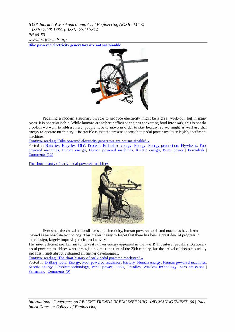
IOSR Journal of Mechanical and Civil Engineering (IOSR-JMCE)
e-ISSN 2278-1684 p-ISSN 2320-334X
PP 64-83
wwwiosrjournalsorg
International Conference on RECENT TRENDS IN ENGINEERING AND MANAGEMENT 75 | Page
Indra Ganesan College of Engineering
Balancing Drum
Two forces acting on the balancing drum are
i) Towards the discharge end which is discharge pressure multiplied by the front balancing area=F1
ii) Towards the suction end which is back pressure or pressure in the balancing chamber multiplied by back
balancing area=F2
As the cross section area on two sides is equal but the pressure on impeller side is high therefore force F1gtF2
Therefore the axial thrust generated in the multistage single suction impeller assembly is counter balanced by
the additional balancing device
Balancing Disc
Axial Clearance
Connected to suction
side of pump
Radial
Clearance Balance drum
bush Balancing
drum
Connected to
suction side of
pump
Radial Clearances
in two steps
Connected to suction
side of pump
Stepped Drum
Axial Clearance
IOSR Journal of Mechanical and Civil Engineering (IOSR-JMCE)
e-ISSN 2278-1684 p-ISSN 2320-334X
PP 64-83
wwwiosrjournalsorg
International Conference on RECENT TRENDS IN ENGINEERING AND MANAGEMENT 76 | Page
Indra Ganesan College of Engineering
Balancing Disc
The functioning of the balancing disc is same as that of balancing drum This is a compact device as
compared to balancing drum and is employed for comparatively smaller high pressure pumps In this device a
balancing disc is allowed to rotate with the shaft and this disc is separated from the balancing disc head which
is fixed to the pump casing with a small axial clearance The back of the balancing disc is subject to the
balancing chamber backpressure and the disc face is subjected to the discharge pressure of the pump There is a
continuous leakage through the axial clearance between the disc and the disc head and fluid flows into the
balancing chamber If the axial thrust of the impeller at any moment exceeds the thrust on the disc the disc
assembly moved towards the disc head reducing the axial clearance between the disc and disc head and reduced
the leakage which in turn lowers the back pressure in the balancing chamber This lowering of pressure
automatically increase the pressure difference acting on the disc and move it away from the disc head
increasing the clearance until an equilibrium condition is reached
Combination of Balancing drum and Balancing disc
Material of Construction of Pump Components
Except the mechanical seal mating faces none of the pump components comes in direct contact with
each other however the service of the pump in which it has to perform dictates the material of construction of
the pump components The following criteria should be considered important in the selection of MOC of the
pump components
i) Corrosion Resistance
ii) Abrasive Wear Resistance
iii) Cavitations Resistance
iv) Strength
v) Tensile Strength
vi) Endurance Limits
vii) Fatigue Strength
viii) Cost
ix) Maintenance
All components of pump may not be required to fulfill all above mentioned criteria Depending upon
the function it has to perform different components require meeting some or all the above criteria to be found
suitable for selection eg MOC of an impeller is required to meet requirements of corrosion resistance abrasive
wear resistance cavitations resistance shall be suitable for casting and machining properties but for shaft of
pump it is required to meet only endurance limits tensile strength hardness corrosion resistance and machining
properties
For pump casing material of construction shall have properties equivalent to impeller MOC
The most widely used materials in pump components are cast iron bronze cast steel austenite steel
and marten site steel and different grades of plastics selected according to application During selection of
material cost and availability should also be considered Unnecessary costly material should not be used unless
it is required for the service
Future maintenance shall also be a point to consider for the selection of the material of construction of
the components Some of the components are required to be replaced during the normal operation after normal
Axial
Clearance
Radial
clearance
Connected to
suction side of
pump
Combined Disc
Drum
IOSR Journal of Mechanical and Civil Engineering (IOSR-JMCE)
e-ISSN 2278-1684 p-ISSN 2320-334X
PP 64-83
wwwiosrjournalsorg
International Conference on RECENT TRENDS IN ENGINEERING AND MANAGEMENT 77 | Page
Indra Ganesan College of Engineering
wear amp tear however major components are designed to perform for the service life but maintenance of all parts
shall be considered at the time of selection
Mechanical seal
Mechanical seals are the positive sealing devices used for the sealing of fluids at the shaft end of the
pumps Now days in petrochemical industries and refineries mechanical seals as per API 682 are only approved
seal designs which can be used on pumps Very stringent requirement of API code have forced seal designers
and manufactures to innovate newer quality products to enhance the seal efficiencies
The conventional stuffing box design with gland packing rings is impractical for many service
conditions In the ordinary stuffing box the sealing between the rotating shaft and the stationary gland casing
(where the shaft penetrates the casing) is accomplished by means of gland packing ring elements held tightly in
the stuffing box around the shaft sleeve and gland follower After certain time of operation the gland packing
leakages starts due to nominal wearing Gland follower is further tightened to stop the leakages
In this way the shaftsleeve and gland pickings get worn out and the renewal of the parts has to be done
for further service In gland packing as the sealing is achieved by tightening of the packing rings directly
between the rotating and stationary parts lot of energy or power is lost
To eliminate this problem and where minimum leakages is required due to expensive or hazardous
chemicals Mechanical seal is required to be installed In big cooling water pumps the replacement of gland
packing with mechanical seals gives benefit of power up to 7
The mechanical seal is a device where two mating surfaces (one is rotating with the shaft and another is
stationary) are located in a plane perpendicular to the shaft axis The two mating surfaces are highly polished
and of dissimilar material of which one is keyed to the shaft shaft sleeve to rotate with the shaft and another
one is fixed in the seal chamberhousing which seal the liquid The basic objective of the mechanical seal
assembly is to prevent leakages of fluid Other than these two main parts there are number of elastomers to
prevent path of leakages through sleeve sealing faces etc springs and spring retainer to exert axial force
gaskets gland plates sleeve etc The fundamental principle of mechanical seal operation is the development and
maintain of liquid film between the two mating surfaces This microscopic film of liquids acts as a cushion for
the seal faces preventing and minimizing wear and dissipation of heat generated due to rubbing action The
rotating face may be of carbon graphite tungsten carbide silicon carbide and the stationery face may be of one
of the above but if the stationary face is carbon graphite then the rotating face should be of dissimilar material
of silicon carbidetungsten carbide and vice versa ie if the stationary face is soft then the rotating face should
be hard or vice versa
This selection of material varies from manufacturer to manufacturer and both have some advantage
and disadvantages
A single spring dual direction seal
Some important maintenance tips during installation of mechanical seal and for its better life are as
below
a) Stuffing box face
The stuffing box face should be square or perpendicular to the shaft axis otherwise resulting in wrong fixing of
stationary element of the seal in gland plate This will results in seal wobble and not having full face contact in
running and rotary head may get elliptical movement against stationary
b) Concentricity of the stuffing box The stuffing box should be concentric to the shaft axis within 008mm
c) Lateral or axial movement of shaft (end play) The mechanical seal cannot function satisfactorily with great
amount of end play If the hydraulic condition changes which happens frequently and if the hydraulic axial
balance is not effective the shaft may float and leading to seal troubles The total amount of shaftrotor end play
should be within 008mm ~ 02mm
IOSR Journal of Mechanical and Civil Engineering (IOSR-JMCE)
e-ISSN 2278-1684 p-ISSN 2320-334X
PP 64-83
wwwiosrjournalsorg
International Conference on RECENT TRENDS IN ENGINEERING AND MANAGEMENT 78 | Page
Indra Ganesan College of Engineering
d) Radial movement of shaft (whip or deflection) Excessive whip or deflection can lead to seal failure and poor
sealing performance The radial movement of shaft should be 005mm ~ 008mm
e) Alignment of driver Driver alignment is by far the most frequent encountered pump problem The poor
alignment causes axial and radial vibrations resulting in failure of seal
21Characteristic of Centrifugal pumps
The key performance parameters of centrifugal pumps are capacity head BEP (Best Efficiency Point)
and specific speed The pump curves provide the operating window within which these parameters can be varied
for satisfactorily pump operation
End user supplies the data of the requirements and manufacturer makes the pump to full fill the
requirement of the end user Basic requirements and manufactured product performances are plotted on the
graph and the intersecting points are known as rated capacity This graph of plots of performance of pump is
known as performance curves or characteristic curves of the pump
Inability to deliver the desired flow and head is one of the most common conditions for making a pump
out of service Many times when the pumps are opened with low or no delivery conditions but on opening no
fault is observed
In such conditions there are three type of problem which mostly encountered are
-Design error
-Poor process operation
-Poor maintenance practices
These problems can be identified when the current performance of the pump is judged against the
characteristics of the pump The deteriorated parameter shall be further analyzed and then the problem shall be
settled
The performance of any pumping system can be marked in terms of its capacity or flow (Q) and
pressure (head)The variation curves of capacity versus pressure of a particular pump are known as pump
performance curve
The plot starts at zero flow and the head at this point corresponds to the shut off head of the specific
pump The curve then decreases to a point where the flow is maximum and the head is minimum This point is
called run-out point The pump curve is relatively flat and the head decreases gradually as the flow increases
Beyond the run-out point the pump cannot operate The pumprsquos range of operation is from the shut-off head
point to the run-out point
V RECIPROCATING PUMP
IOSR Journal of Mechanical and Civil Engineering (IOSR-JMCE)
e-ISSN 2278-1684 p-ISSN 2320-334X
PP 64-83
wwwiosrjournalsorg
International Conference on RECENT TRENDS IN ENGINEERING AND MANAGEMENT 79 | Page
Indra Ganesan College of Engineering
Reciprocating Pumps- classifications-construction and working of single acting and double acting
reciprocating pumps-plunger and piston pumps-discharge of a reciprocating pump-theoretical power required-
coefficient of discharge-slip-problems-negative slip-indicator diagram-separation-air vessel (functions and
working) Special pumps-jet pump-Turbine pump-Submersible pump
Reciprocating pumps These types of pump operate by using a reciprocating piston The liquid enters a pumping chamber via
an inlet valve and is pushed out via a outlet valve by the action of the piston or diaphragm
Reciprocating pumps are generally very efficient and are suitable for very high heads at low flows
This type of pump is self priming as it can draw liquid from a level below the suction flange even if the suction
pipe is not evacuated The pump delivers reliable discharge flows and is often used for metering duties
delivering accurate quantities of fluid
The reciprocating pump is not tolerant to solid particles and delivers a highly pulsed flow If a smooth
flow is required then the discharge flow system has to include additional features such as accumulators to
provide even flows
Reciprocating pumps designed for delivering high pressures must include methods for releasing
excessive fluid pressures The pumps should include for built in relief valves or relief valves should be
included in the fluid circuit which cannot be isolated from the pump This feature is not required for safety for
the air operated diaphragm valve
VI MAJOR COMPONETS OF PEDALOPERATED DRILLIING MACHINE
1 Piston
2 Cylinder
3 Rod
4 Water seal
5 pedal link
1 PISTON
Piston is used to pressure creating component It is made of steel It is reciprocating in side the
cylinder Very close tolerance is maintained with cylinder
1 Cylinder
Cylinder is used to reciprocate the cylinder with close tolerance Piston will develop the maximum
pressure Cylinder is made of mils steel
2 Rod
It is connect the piston and foot pedal It is also used push the piston according to the foot pedal action
Rod is used to connect the piston and foot pedal pump link The maximum pressure is achieved pumping lifting
height It will convert angularity motion to linear motion
IOSR Journal of Mechanical and Civil Engineering (IOSR-JMCE)
e-ISSN 2278-1684 p-ISSN 2320-334X
PP 64-83
wwwiosrjournalsorg
International Conference on RECENT TRENDS IN ENGINEERING AND MANAGEMENT 80 | Page
Indra Ganesan College of Engineering
3 Water seal
The primary seal consists of two rings (a primary and mating ring) that are lapped to a high degree of flatness
and then loaded against one another by means of a spring One of these rings will rotate in accordance with the
shaft of the pump and rub against the other ring creating a seal for the fluid The material composition of the
primary and mating rings varies depending on duty and life expectancy goals for the application
The secondary seal consists of molded rubber components which are held in place via an adhesive or
mechanical press These secondary sealing components form the seal between the rotating faces and the metallic
components (spring retainer ferrules and sleeve) used to load the faces and to allow the pump builder to install
the seal quickly and efficiently
4 Pedal link
This type link is used to connect the piston rod and foot step mechanism This link is very sturdy due it
will withstand cyclic load
VII DESIGN ASPECTS AND OPERATION PROPERTIES OF MILD STEEL
PHYSICAL PROPERTY
Density - 7860 Kgm3
Melting point - 1427c
Thermal conductivity - 63 W m K
CARBON CONTENT
Low Carbon (or) Mild steel - 015 to045 carbon
MECHANICAL PROPERTY
o Elasticity
o Ductility
o Toughness
o Weld ability
In our design screw type clamp Body of jig have a main part hence the calculations are concentrated on it
VIII DESIGN CALCULATIONS FOR PUMP To calculate the volume of the cylinder
Volume=Arealength
Area= (π4D2)
X L
D=Diameter of the piston
D=110mm
IOSR Journal of Mechanical and Civil Engineering (IOSR-JMCE)
e-ISSN 2278-1684 p-ISSN 2320-334X
PP 64-83
wwwiosrjournalsorg
International Conference on RECENT TRENDS IN ENGINEERING AND MANAGEMENT 81 | Page
Indra Ganesan College of Engineering
L=90mm
=85529m3
DESIGN FOR CYLINDER
The force exerted on in stroke can be expressed as
F = p π (d12 - d2
2) 4
Where
P = Initial pressure (Nmsup2)
d1 = full bore piston diameter (m)
d2 = piston rod diameter (m)
For Example
P = 1 bar (assumed)
π = 314
d1 = 011m
d2 = 0010m
F = p π (d12 - d2
2) 4
F = 1x105x314x (011
2 ndash 0010
2) 4
F = 1884955592x2275x10-3
4
F = 942 N
IX OPERATIONS INVOLVED o Turning (facing plain turning step turning threading etc)
o Facing (flat surface)
o Drilling
o Gas cutting (flat plate cylindrical rods)
o Shaping
o Welding
o Tapping
o Thread cutting
TURNING
Turning is the operation of reducing a cylindrical surface by removing material from the outside
diameter of a work piece It is done by rotating the work piece about the lathe axis and feeding the tool parallel
to the lathe axis Due to this operation screw rod and head are done by the turning operation to get the required
shape
FACING
Machining the end of the work piece to produce flat surface is called facing Due to this the plate can get
flat surface have done by the facing operation
DRILLING Drilling is the operation of producing cylindrical hole in work piece It is done by rotating the cutting
edge of the cutter known as drill bit In this Project the jig plates require holes for locating indexing plate and
screw rod drill bush assembly These holes are done by conventional vertical drilling machine
THREAD CUTTING
Thread cutting is the operation of forming external thread of required diameter of rod by using a
multipoint tool is called thread This process is used in screw clamp to done on the rod which is used for the
movement of the movable plate
IOSR Journal of Mechanical and Civil Engineering (IOSR-JMCE)
e-ISSN 2278-1684 p-ISSN 2320-334X
PP 64-83
wwwiosrjournalsorg
International Conference on RECENT TRENDS IN ENGINEERING AND MANAGEMENT 82 | Page
Indra Ganesan College of Engineering
FINE GRINDING
It is nothing but the grinding process which is done as smooth with fine grains This is done as the
each plate and base plate for good surface finish It is done by conventional grinding machine
GAS CUTTING
It is used to break are cut the plates In this project it is used to cut the raw materials such as plates
This done by gas cutting machine
SHAPING
Shaping operation is used to reduce the dimensions of the plates In this project the plates are in need of
shaping process It is done by shaping machine
WELDING
It is the process which is used to join two is more similar materials as well as dissimilar materials In
this project it is used to join the jig plate one to another This is done by arc welding machine
X WORKING PRINCIPLE
Pumps are a common means of lifting water from a clean ground water source to a useful point of
access but all pumps have moving parts and are therefore destined to break proper selection of a pump will
reduce undesirable downtime and will empower the local community to manage their water source
Here we use the foot pedal pump powered by our legs instead of arms to lift the water from a depth
range of seven meters Throughout history human energy has generally been applied through the use of the
arms hands and back With minor exceptions it was only with the invention of the sliding-seat rowing shell
and particularly of the bicycle that legs also began to be considered as a normal means of developing power
from human muscles
A person can generate four times more (14 horse power (hp)) by pedaling than by hand ndashcranking At
the rate of 14hp continuous pedaling can be done for only short periods about 10 minutes However pedaling
at half this power (18 hp) can be sustained for around 60 minutes
The main use of pedal power today is still for bicycling at least in the high- power range (75 watts and above of
mechanical power) In the lower-power range there are a number of use of pedal power for agriculture
construction water pumping and electrical generation that seem to be potentially advantages at least when
electrical or internal-combustion engine power is unavailable or very expensive
XI COST ESTIMATION TOTAL = 358000
LABOUR COST
Lathe drilling shaping welding riveting turning painting surface grinding and gas cutting
SNO Name of the part Weight in kg Cost RS
1 Cylinder arrangement 3 1680
2 Pedal mechanism 400
3 Assembly work 1200
4 Hose accessories 300
IOSR Journal of Mechanical and Civil Engineering (IOSR-JMCE)
e-ISSN 2278-1684 p-ISSN 2320-334X
PP 64-83
wwwiosrjournalsorg
International Conference on RECENT TRENDS IN ENGINEERING AND MANAGEMENT 83 | Page
Indra Ganesan College of Engineering
Cost = Rs 180000
TOTAL COST
Total cost = material cost + Labour cost
= 3580 + 1800
= 538000
Total cost for this project = Rs 558000
XII ADVANTAGES AND APPLICATIONS ADVANTAGES
o It is used for to achieve manual operated water pumping non automated by simple mechanism
o Its operation and maintenance is very simple
o It is compact and portable
o It is simple and rigid in construction
o Manufacturing cost is lesser than modern water pumping machine
o It provides better speed changes method on the driving unit
o Power saved and good exercise for all people
APPLICATIONS
This device find place in almost all industries
DISADVANTAGES
1 Continuous pedaling action is required for system operation so that lot of work can not executed
XIII CONCLUSION This project focused on modeling design and control of pedal operated water pumping with emphasis
on lightweight portable appliances An innovative method of minimizing manual stress and thus reliably
stabilizing the pumping was also presented The project carried out by us made an impressing task in the
industrial purpose It is very useful for the small scale works
This project has been designed to perform the entire requirement task which has also been provided
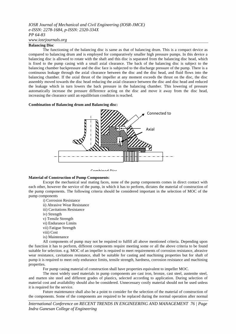
IOSR Journal of Mechanical and Civil Engineering (IOSR-JMCE)
e-ISSN 2278-1684 p-ISSN 2320-334X
PP 64-83
wwwiosrjournalsorg
International Conference on RECENT TRENDS IN ENGINEERING AND MANAGEMENT 77 | Page
Indra Ganesan College of Engineering
wear amp tear however major components are designed to perform for the service life but maintenance of all parts
shall be considered at the time of selection
Mechanical seal
Mechanical seals are the positive sealing devices used for the sealing of fluids at the shaft end of the
pumps Now days in petrochemical industries and refineries mechanical seals as per API 682 are only approved
seal designs which can be used on pumps Very stringent requirement of API code have forced seal designers
and manufactures to innovate newer quality products to enhance the seal efficiencies
The conventional stuffing box design with gland packing rings is impractical for many service
conditions In the ordinary stuffing box the sealing between the rotating shaft and the stationary gland casing
(where the shaft penetrates the casing) is accomplished by means of gland packing ring elements held tightly in
the stuffing box around the shaft sleeve and gland follower After certain time of operation the gland packing
leakages starts due to nominal wearing Gland follower is further tightened to stop the leakages
In this way the shaftsleeve and gland pickings get worn out and the renewal of the parts has to be done
for further service In gland packing as the sealing is achieved by tightening of the packing rings directly
between the rotating and stationary parts lot of energy or power is lost
To eliminate this problem and where minimum leakages is required due to expensive or hazardous
chemicals Mechanical seal is required to be installed In big cooling water pumps the replacement of gland
packing with mechanical seals gives benefit of power up to 7
The mechanical seal is a device where two mating surfaces (one is rotating with the shaft and another is
stationary) are located in a plane perpendicular to the shaft axis The two mating surfaces are highly polished
and of dissimilar material of which one is keyed to the shaft shaft sleeve to rotate with the shaft and another
one is fixed in the seal chamberhousing which seal the liquid The basic objective of the mechanical seal
assembly is to prevent leakages of fluid Other than these two main parts there are number of elastomers to
prevent path of leakages through sleeve sealing faces etc springs and spring retainer to exert axial force
gaskets gland plates sleeve etc The fundamental principle of mechanical seal operation is the development and
maintain of liquid film between the two mating surfaces This microscopic film of liquids acts as a cushion for
the seal faces preventing and minimizing wear and dissipation of heat generated due to rubbing action The
rotating face may be of carbon graphite tungsten carbide silicon carbide and the stationery face may be of one
of the above but if the stationary face is carbon graphite then the rotating face should be of dissimilar material
of silicon carbidetungsten carbide and vice versa ie if the stationary face is soft then the rotating face should
be hard or vice versa
This selection of material varies from manufacturer to manufacturer and both have some advantage
and disadvantages
A single spring dual direction seal
Some important maintenance tips during installation of mechanical seal and for its better life are as
below
a) Stuffing box face
The stuffing box face should be square or perpendicular to the shaft axis otherwise resulting in wrong fixing of
stationary element of the seal in gland plate This will results in seal wobble and not having full face contact in
running and rotary head may get elliptical movement against stationary
b) Concentricity of the stuffing box The stuffing box should be concentric to the shaft axis within 008mm
c) Lateral or axial movement of shaft (end play) The mechanical seal cannot function satisfactorily with great
amount of end play If the hydraulic condition changes which happens frequently and if the hydraulic axial
balance is not effective the shaft may float and leading to seal troubles The total amount of shaftrotor end play
should be within 008mm ~ 02mm
IOSR Journal of Mechanical and Civil Engineering (IOSR-JMCE)
e-ISSN 2278-1684 p-ISSN 2320-334X
PP 64-83
wwwiosrjournalsorg
International Conference on RECENT TRENDS IN ENGINEERING AND MANAGEMENT 78 | Page
Indra Ganesan College of Engineering
d) Radial movement of shaft (whip or deflection) Excessive whip or deflection can lead to seal failure and poor
sealing performance The radial movement of shaft should be 005mm ~ 008mm
e) Alignment of driver Driver alignment is by far the most frequent encountered pump problem The poor
alignment causes axial and radial vibrations resulting in failure of seal
21Characteristic of Centrifugal pumps
The key performance parameters of centrifugal pumps are capacity head BEP (Best Efficiency Point)
and specific speed The pump curves provide the operating window within which these parameters can be varied
for satisfactorily pump operation
End user supplies the data of the requirements and manufacturer makes the pump to full fill the
requirement of the end user Basic requirements and manufactured product performances are plotted on the
graph and the intersecting points are known as rated capacity This graph of plots of performance of pump is
known as performance curves or characteristic curves of the pump
Inability to deliver the desired flow and head is one of the most common conditions for making a pump
out of service Many times when the pumps are opened with low or no delivery conditions but on opening no
fault is observed
In such conditions there are three type of problem which mostly encountered are
-Design error
-Poor process operation
-Poor maintenance practices
These problems can be identified when the current performance of the pump is judged against the
characteristics of the pump The deteriorated parameter shall be further analyzed and then the problem shall be
settled
The performance of any pumping system can be marked in terms of its capacity or flow (Q) and
pressure (head)The variation curves of capacity versus pressure of a particular pump are known as pump
performance curve
The plot starts at zero flow and the head at this point corresponds to the shut off head of the specific
pump The curve then decreases to a point where the flow is maximum and the head is minimum This point is
called run-out point The pump curve is relatively flat and the head decreases gradually as the flow increases
Beyond the run-out point the pump cannot operate The pumprsquos range of operation is from the shut-off head
point to the run-out point
V RECIPROCATING PUMP
IOSR Journal of Mechanical and Civil Engineering (IOSR-JMCE)
e-ISSN 2278-1684 p-ISSN 2320-334X
PP 64-83
wwwiosrjournalsorg
International Conference on RECENT TRENDS IN ENGINEERING AND MANAGEMENT 79 | Page
Indra Ganesan College of Engineering
Reciprocating Pumps- classifications-construction and working of single acting and double acting
reciprocating pumps-plunger and piston pumps-discharge of a reciprocating pump-theoretical power required-
coefficient of discharge-slip-problems-negative slip-indicator diagram-separation-air vessel (functions and
working) Special pumps-jet pump-Turbine pump-Submersible pump
Reciprocating pumps These types of pump operate by using a reciprocating piston The liquid enters a pumping chamber via
an inlet valve and is pushed out via a outlet valve by the action of the piston or diaphragm
Reciprocating pumps are generally very efficient and are suitable for very high heads at low flows
This type of pump is self priming as it can draw liquid from a level below the suction flange even if the suction
pipe is not evacuated The pump delivers reliable discharge flows and is often used for metering duties
delivering accurate quantities of fluid
The reciprocating pump is not tolerant to solid particles and delivers a highly pulsed flow If a smooth
flow is required then the discharge flow system has to include additional features such as accumulators to
provide even flows
Reciprocating pumps designed for delivering high pressures must include methods for releasing
excessive fluid pressures The pumps should include for built in relief valves or relief valves should be
included in the fluid circuit which cannot be isolated from the pump This feature is not required for safety for
the air operated diaphragm valve
VI MAJOR COMPONETS OF PEDALOPERATED DRILLIING MACHINE
1 Piston
2 Cylinder
3 Rod
4 Water seal
5 pedal link
1 PISTON
Piston is used to pressure creating component It is made of steel It is reciprocating in side the
cylinder Very close tolerance is maintained with cylinder
1 Cylinder
Cylinder is used to reciprocate the cylinder with close tolerance Piston will develop the maximum
pressure Cylinder is made of mils steel
2 Rod
It is connect the piston and foot pedal It is also used push the piston according to the foot pedal action
Rod is used to connect the piston and foot pedal pump link The maximum pressure is achieved pumping lifting
height It will convert angularity motion to linear motion
IOSR Journal of Mechanical and Civil Engineering (IOSR-JMCE)
e-ISSN 2278-1684 p-ISSN 2320-334X
PP 64-83
wwwiosrjournalsorg
International Conference on RECENT TRENDS IN ENGINEERING AND MANAGEMENT 80 | Page
Indra Ganesan College of Engineering
3 Water seal
The primary seal consists of two rings (a primary and mating ring) that are lapped to a high degree of flatness
and then loaded against one another by means of a spring One of these rings will rotate in accordance with the
shaft of the pump and rub against the other ring creating a seal for the fluid The material composition of the
primary and mating rings varies depending on duty and life expectancy goals for the application
The secondary seal consists of molded rubber components which are held in place via an adhesive or
mechanical press These secondary sealing components form the seal between the rotating faces and the metallic
components (spring retainer ferrules and sleeve) used to load the faces and to allow the pump builder to install
the seal quickly and efficiently
4 Pedal link
This type link is used to connect the piston rod and foot step mechanism This link is very sturdy due it
will withstand cyclic load
VII DESIGN ASPECTS AND OPERATION PROPERTIES OF MILD STEEL
PHYSICAL PROPERTY
Density - 7860 Kgm3
Melting point - 1427c
Thermal conductivity - 63 W m K
CARBON CONTENT
Low Carbon (or) Mild steel - 015 to045 carbon
MECHANICAL PROPERTY
o Elasticity
o Ductility
o Toughness
o Weld ability
In our design screw type clamp Body of jig have a main part hence the calculations are concentrated on it
VIII DESIGN CALCULATIONS FOR PUMP To calculate the volume of the cylinder
Volume=Arealength
Area= (π4D2)
X L
D=Diameter of the piston
D=110mm
IOSR Journal of Mechanical and Civil Engineering (IOSR-JMCE)
e-ISSN 2278-1684 p-ISSN 2320-334X
PP 64-83
wwwiosrjournalsorg
International Conference on RECENT TRENDS IN ENGINEERING AND MANAGEMENT 81 | Page
Indra Ganesan College of Engineering
L=90mm
=85529m3
DESIGN FOR CYLINDER
The force exerted on in stroke can be expressed as
F = p π (d12 - d2
2) 4
Where
P = Initial pressure (Nmsup2)
d1 = full bore piston diameter (m)
d2 = piston rod diameter (m)
For Example
P = 1 bar (assumed)
π = 314
d1 = 011m
d2 = 0010m
F = p π (d12 - d2
2) 4
F = 1x105x314x (011
2 ndash 0010
2) 4
F = 1884955592x2275x10-3
4
F = 942 N
IX OPERATIONS INVOLVED o Turning (facing plain turning step turning threading etc)
o Facing (flat surface)
o Drilling
o Gas cutting (flat plate cylindrical rods)
o Shaping
o Welding
o Tapping
o Thread cutting
TURNING
Turning is the operation of reducing a cylindrical surface by removing material from the outside
diameter of a work piece It is done by rotating the work piece about the lathe axis and feeding the tool parallel
to the lathe axis Due to this operation screw rod and head are done by the turning operation to get the required
shape
FACING
Machining the end of the work piece to produce flat surface is called facing Due to this the plate can get
flat surface have done by the facing operation
DRILLING Drilling is the operation of producing cylindrical hole in work piece It is done by rotating the cutting
edge of the cutter known as drill bit In this Project the jig plates require holes for locating indexing plate and
screw rod drill bush assembly These holes are done by conventional vertical drilling machine
THREAD CUTTING
Thread cutting is the operation of forming external thread of required diameter of rod by using a
multipoint tool is called thread This process is used in screw clamp to done on the rod which is used for the
movement of the movable plate
IOSR Journal of Mechanical and Civil Engineering (IOSR-JMCE)
e-ISSN 2278-1684 p-ISSN 2320-334X
PP 64-83
wwwiosrjournalsorg
International Conference on RECENT TRENDS IN ENGINEERING AND MANAGEMENT 82 | Page
Indra Ganesan College of Engineering
FINE GRINDING
It is nothing but the grinding process which is done as smooth with fine grains This is done as the
each plate and base plate for good surface finish It is done by conventional grinding machine
GAS CUTTING
It is used to break are cut the plates In this project it is used to cut the raw materials such as plates
This done by gas cutting machine
SHAPING
Shaping operation is used to reduce the dimensions of the plates In this project the plates are in need of
shaping process It is done by shaping machine
WELDING
It is the process which is used to join two is more similar materials as well as dissimilar materials In
this project it is used to join the jig plate one to another This is done by arc welding machine
X WORKING PRINCIPLE
Pumps are a common means of lifting water from a clean ground water source to a useful point of
access but all pumps have moving parts and are therefore destined to break proper selection of a pump will
reduce undesirable downtime and will empower the local community to manage their water source
Here we use the foot pedal pump powered by our legs instead of arms to lift the water from a depth
range of seven meters Throughout history human energy has generally been applied through the use of the
arms hands and back With minor exceptions it was only with the invention of the sliding-seat rowing shell
and particularly of the bicycle that legs also began to be considered as a normal means of developing power
from human muscles
A person can generate four times more (14 horse power (hp)) by pedaling than by hand ndashcranking At
the rate of 14hp continuous pedaling can be done for only short periods about 10 minutes However pedaling
at half this power (18 hp) can be sustained for around 60 minutes
The main use of pedal power today is still for bicycling at least in the high- power range (75 watts and above of
mechanical power) In the lower-power range there are a number of use of pedal power for agriculture
construction water pumping and electrical generation that seem to be potentially advantages at least when
electrical or internal-combustion engine power is unavailable or very expensive
XI COST ESTIMATION TOTAL = 358000
LABOUR COST
Lathe drilling shaping welding riveting turning painting surface grinding and gas cutting
SNO Name of the part Weight in kg Cost RS
1 Cylinder arrangement 3 1680
2 Pedal mechanism 400
3 Assembly work 1200
4 Hose accessories 300
IOSR Journal of Mechanical and Civil Engineering (IOSR-JMCE)
e-ISSN 2278-1684 p-ISSN 2320-334X
PP 64-83
wwwiosrjournalsorg
International Conference on RECENT TRENDS IN ENGINEERING AND MANAGEMENT 83 | Page
Indra Ganesan College of Engineering
Cost = Rs 180000
TOTAL COST
Total cost = material cost + Labour cost
= 3580 + 1800
= 538000
Total cost for this project = Rs 558000
XII ADVANTAGES AND APPLICATIONS ADVANTAGES
o It is used for to achieve manual operated water pumping non automated by simple mechanism
o Its operation and maintenance is very simple
o It is compact and portable
o It is simple and rigid in construction
o Manufacturing cost is lesser than modern water pumping machine
o It provides better speed changes method on the driving unit
o Power saved and good exercise for all people
APPLICATIONS
This device find place in almost all industries
DISADVANTAGES
1 Continuous pedaling action is required for system operation so that lot of work can not executed
XIII CONCLUSION This project focused on modeling design and control of pedal operated water pumping with emphasis
on lightweight portable appliances An innovative method of minimizing manual stress and thus reliably
stabilizing the pumping was also presented The project carried out by us made an impressing task in the
industrial purpose It is very useful for the small scale works
This project has been designed to perform the entire requirement task which has also been provided
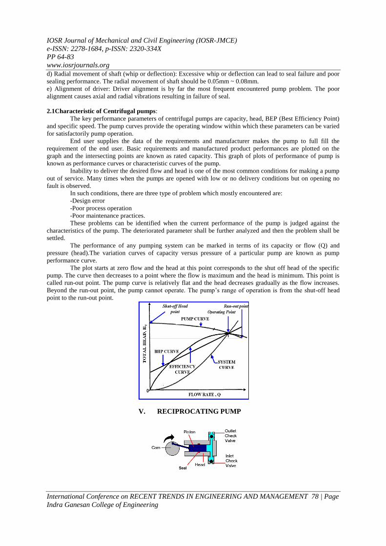
IOSR Journal of Mechanical and Civil Engineering (IOSR-JMCE)
e-ISSN 2278-1684 p-ISSN 2320-334X
PP 64-83
wwwiosrjournalsorg
International Conference on RECENT TRENDS IN ENGINEERING AND MANAGEMENT 83 | Page
Indra Ganesan College of Engineering
Cost = Rs 180000
TOTAL COST
Total cost = material cost + Labour cost
= 3580 + 1800
= 538000
Total cost for this project = Rs 558000
XII ADVANTAGES AND APPLICATIONS ADVANTAGES
o It is used for to achieve manual operated water pumping non automated by simple mechanism
o Its operation and maintenance is very simple
o It is compact and portable
o It is simple and rigid in construction
o Manufacturing cost is lesser than modern water pumping machine
o It provides better speed changes method on the driving unit
o Power saved and good exercise for all people
APPLICATIONS
This device find place in almost all industries
DISADVANTAGES
1 Continuous pedaling action is required for system operation so that lot of work can not executed
XIII CONCLUSION This project focused on modeling design and control of pedal operated water pumping with emphasis
on lightweight portable appliances An innovative method of minimizing manual stress and thus reliably
stabilizing the pumping was also presented The project carried out by us made an impressing task in the
industrial purpose It is very useful for the small scale works
This project has been designed to perform the entire requirement task which has also been provided