design and fabrication of full scale prototype truck chassis. volume 1. wheels
TRANSCRIPT

S•
T C %0TAC M
TECHNICAL REPORTNO.NO. 12622 VOL 1
DESIGN AND FABRICATION OF* FULL SCALE PROTOTYPE TRUCK
CHASSIS (VOLUME 1 - - WHEELS)JULY 1984
Final Report
CONTRACT NO. DAAK30-79-C-0147
a by
by Frank Y. Soliman a
Ewald Associates, Inc."19450 Fitzpatrick :
Detroit, MI 48228a
a andAvery H. Fisher -i1 1 :a US Army Tank-Automotive CommandATTN: DRSTA-RSCWarren, MI 48090
• ..................... ... .... .a...a.........0..6........ ....................... ........
U.S. ARMY TANK-AUTOMOTIVE COMMANDWarren, Michigan 48090
Reproduced FromBest Available Copy

I, . I
S~C E N T E ,,•• TECHNICAL REPORT
.1.
NO. 162VL. I
FULL SCALE PROTOTYPE TRUCKCHASSIS (VOLUME 1i--.WHEELS)
JULY 1984CONTRACT No. DAAK30-79-C,0147 .
EWALD ASSOCIATES, INC.19450 FITZPATRICK
.DETROIT'* MI 48228by ,ANn
AVERY H. FISHERIUS ARMY TANK-AUTOMOTIVE COMMANDATTN: DRSTA-RSCiWARRENN MI 48090
II
U.S. ARMY TANK-AUTOMOTIVE COMMANDRESEARCH AND DEVELOPMENT CENTERWarren, Michigan 48090
NOTICES
This report is not to be construed as an Official Department of theArmy position.
Mention of any trade names or manufacturers in this report shall notbe construed as an Official indorsement or approval of such productor companies by the U.S. Government.
/9
Destroy this report when it is no longer needed. Do not return it to theoriginator.

UnclassifiedSECURITY CLASSIFICATION OF THIS PAGE (When Data Entered)
READ INSTRUCTIONSREPORT DOCUMENTATION PAGE BEFORE COMPLETING FORM1. REPORT NUMBER 2. GOVT ACCESSION NO. 3. RECIPIENT'S CATALOG NUMBER
12622 Vol. I1
4. TITLE (and Subtitle) 5. TYPE OF REPORT & PERIOD COVERED
Design and Fabrication of Full ScalePrototype Truck Chasis and Wheels Final Technical ReportVolume 1 - Wheels 6. PERFORMING ORG. REPORT NUMBER
7. AUTHOR(#) 8. CONTRACT OR GRANT NUMBER(&)
Frank Y. Soliman and Avery H. Fisher DAAK30-79-C-0147
9. PERFORMING ORGANIZATION NAME AND ADDRESS 10. PROGRAM ELEMENT, PROJECT, TASKAREA & WORK UNIT NUMBERS
Ewald Associates, Inc.19450 FitzpatrickDetroit, MI IL162601AH91
I1. CONTROLLING OFFICE NAME AND ADDRESS 12. REPORT DATE
DRSTA-RSC July 1984US Army Tank-Automotive Command 13. NUMBER OF PAGES
Warren, MI 4809014. MONITORING AGENCY NAME & ADDRESS(if different from Controlling Office) 15. SECURITY CLASS. (of this report)
Unclassified
ISa. DECL ASSI FICATION/DOWNGRADINGSCHEDULE
16. DISTRIBUTION STATEMENT (of this Report)
Approve for Public Release, Distribution Unlimited.
17. DISTRIBUTION STATEMENT (of the abstract entered In Block 20, If different from Report)
18. SUPPLEMENTARY NOTES
19. KEY WORDS (Continue on revere* aide If necesary and identify by block number)
Composite MaterialsTruck ComponentsResin Matrix CompositesWheelsFibergl ass-epoxy
2(L ABNTR ACT r(C thau am rover.. .Lh it nacsaarty amd Identify by block number)
The 1100x20 wheel for the M809, M939 truck series was redesigned forstructural composites. Finite element analysis of the design was accomplishedusing material properties developed during this program.
Tooling was designed and manufactured for both the wheel and the lock ring astwo independent molds. Composite wheels and lock rings were manufactured usingcompression molding techniques.
DI JAOmM EDITION OF INOV6GS IS OBSOLETEN 73 Unclassified
SECURITY CLASSIFICATION OF THIS PAGE (When Data Entered)

UnclassifiedSECURITY CLASSIFICATION OF THIS PAGE(WlhmI Data Entered)
Laboratory testing was conducted using SAE J267 A procedures and the IndoorEndurance Test of Specification MIL-T-12459D. The composite wheels performed
well under the fatigue environment but did not pass the Indoor Endurance Test.
2 Unclassified

Table of Contents
Section Title Page
I.0 Introduction 11
2.0 Wheel Design and Engineering 12
2.1 Wheel Design 12
2.2 Design Approach 12
2.3 Wheel Concept 14
3.0 Design Requirements 14
3.1 Imput Loads 15
3.2 Minimum Design Cycle Life 17
4.0 Final Design Concept 17
4.1 External Dimensions 17
4.2 Integral Disc/Rim Assembly 20
5.0 Engineering Analysis 22
5.1 Computer Analysis 22
5.3 Finite Element Presentation of composite wheel 24
5.4 Computer Programs Used in this Analysis 32
6.0 Materials 34
6.1 Discussion 34
6.2 Material Form 37
6.3 Compound 37
6.4 Material Properties 37
7.0 Input Loads 40
7.1 Vertical Loads 40
3

7.2 Side Loads 40
7.3 Resulting Dynamic Loads 40
7.4 Second Loading Condition 41
7.5 Third Loading Condition 41
8.0 Manufacturing 42
8.1 Tooling 42
8.2 Manufacturing Approach 71
8.3 Manufacturing Technique 71
8.4 Composite Laminate Blanking 73
8.5 Weight Control 73
8.6 Wheel Molding 74
8.7 Discussion of the Manufacturing Process 75
9.0 Composite Wheel Testing 75
9.1 Mounting and Demounting 75
9.2 Testing at Budd Wheel 79
9.3 Fatigue Test-Composite Wheel #2 83
9.4 Endurance Test (MIL-T-12549D) 89
10.0 Conclusions 101
11.0 Recommendations 102
Distribution list 103

List of Tables
1. Mechanical Properties of Discontinuous Randomly 38Oriented E-Glass in Vinylester Resins (IsotropicLaminate)
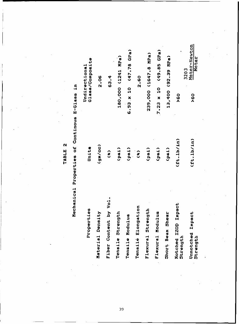
2. Mechanical Properties of Continuous E-Glass in 39Vinylester Resins
3. Load vs Deflection -- Wheel #1 81
4. Load vs Deflection -- Wheel #2 82
5

LIST OF ILLUSTRATIONS
Figure Title Page
1. Composite Wheel Assembly 13
2. Application of Loads During Cornering Fatigue 16
3. Applied Loads on Wheel During Rim Radial 18Fatigue Testing
4. Composite Wheel Design 19
5. Details of the Hybrid Composite Side Ring 21
6. Assembled Composite Wheel with Tire Mounted 23
7. Typical Finite Element Model of a Classic 25Wheel
8. NISA - Finite Element Model of a Wheel and 26Stress Contour Output
9. Fiber Directions with Respect to Global Axis 27X, Y, of Structural Components
10. Orthotropic Lamina Under Biaxial Stress 29
11. Eight Node Isoparametric General Shell Finite 30Element
12. General Shell Element and Various Coordinate 31System
13. Degrees of Freedom of Shell Element Node Point 32
14. Front View of the Composite Wheel Model, with 35Mounting Holes
15. Front View of the Composite Wheel Structural 36Model Simulation
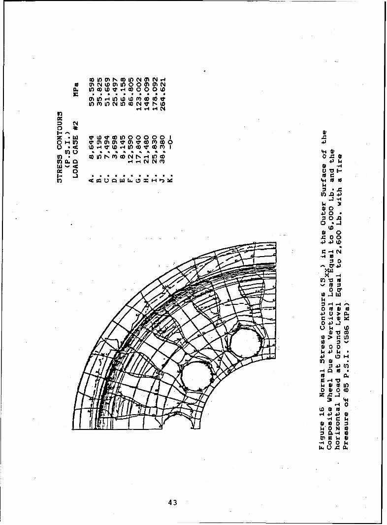
16. Normal Stress Contours (Sxx) in the Outer 43Surface of the Composite Wheel
17. Normal Stress Contours (Syy) in the Outer 44Surface of the Composite Wheel
6

18. Maximum Principle Stress Contours (53) in the 45Outer Surface of the Composite Wheel
19. Von Mises Equivalent Stress Contours (Seq) in 46the Outer Surface of the Composite Wheel
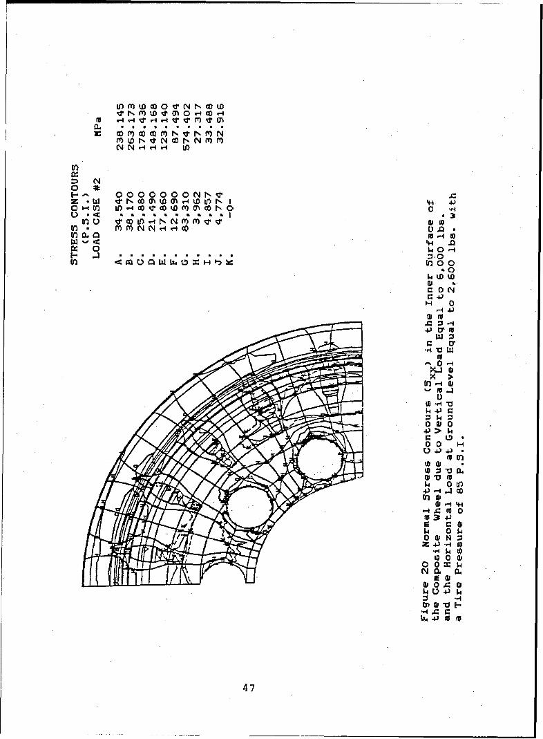
20. Normal Stress Contours (Sxx) in the Inner 47Surface of the Composite Wheel
21. Normal Stress Contours (5yy) in the Inner 48Surface of the Composite Wheel
22. Maximum Principle Stress Contours (53) in the 49Inner Surface of the Composite Wheel
23. Von Mises Equivalent Stress Contours (Se9) in 50the Inner Surface of the Composite Wheel
24. Normal Stress Contours (Sxx) in the Bottom 51Surface of the Composite Wheel
25. Normal Stress Contours (Syy) in the Bottom 521Surface of the Composite Wheel
26. Maximum Principle Stress Contours (53) in the 53Bottom Surface of the Composite Wheel
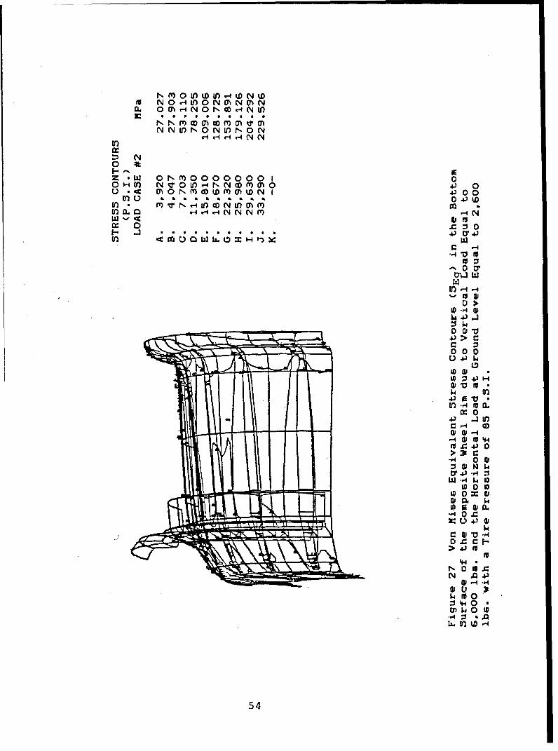
27. Von Mises Equivalent Stress Contours (Seq) in 54the Bottom Surface of the Composite Wheel
28. Normal Stress Contours (Sxx) around the Bolt 55Holes in the Composite Wheel
29. Normal Stress Contours (5yy) around the Bolt 56Holes in the Composite Wheel
30. Maximum Principle Stress Contours (53) around 57the Bolt Holes in the Composite Wheel
31. Von Mises Equivalent Stress Contours (Se9) 58around the Bolt Holes in the Composite Wheel
32. Normal Stress Contours (Sxx) in the Outer 59Surface of the Composite Wheel due to CorneringFatigue Loads
33. Normal Stress Contours (5yy) in the Outer 60Surface of the Composite Wheel due to CorneringFatigue Loads
7

34. Maximum Principle Stress Contours (53) in the 61Outer Surface of the Composite Wheel due toCornering Fatigue Loads
35. Von Mises Equivalent Stress Contours (5eg) in 62the Outer Surface of the Composite Wheel due toCornering Fatigue Loads
36. Normal Stress Contours (Sxx) in the Inner 63Surface of the Composite Wheel due to CorneringFatigue Loads
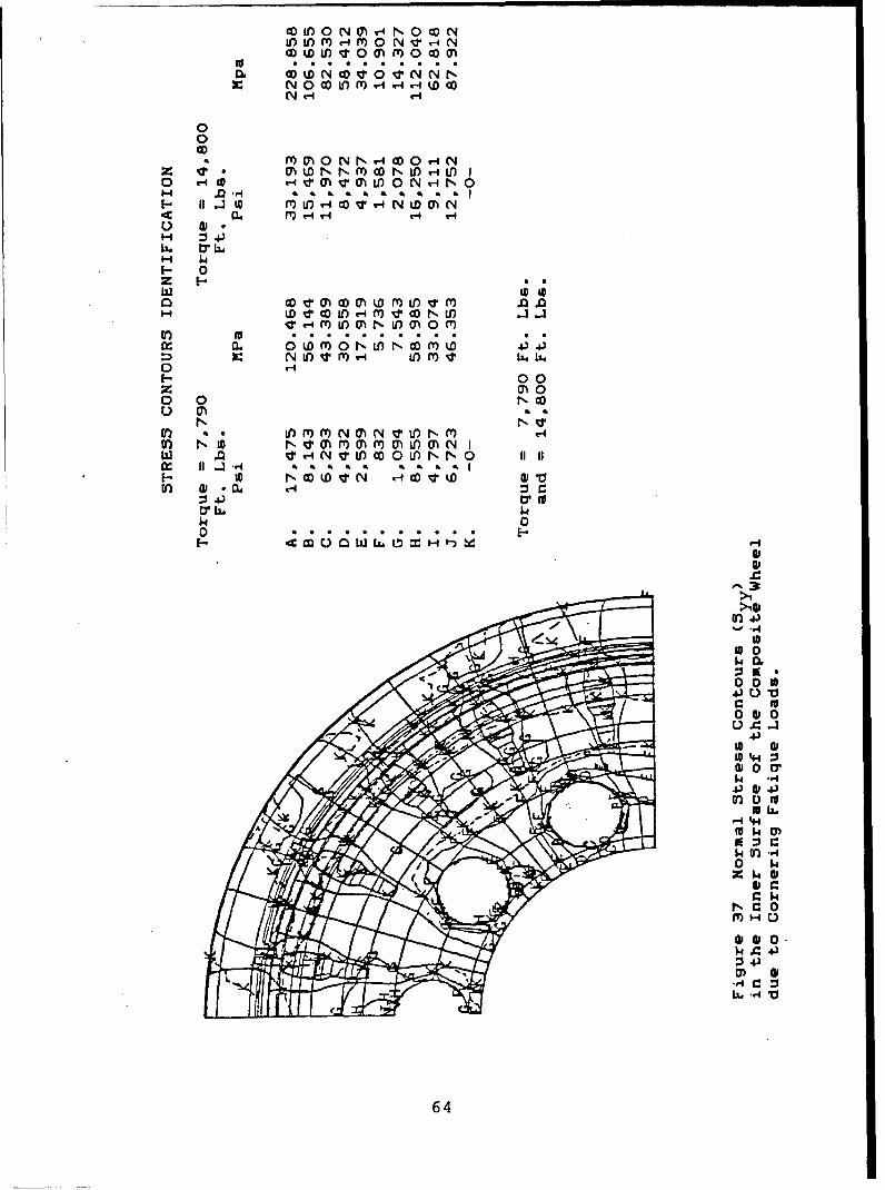
37. Normal Stress Contours (5yy) in the inner 64Surface of the Composite Wheel due to CorneringFatigue Loads
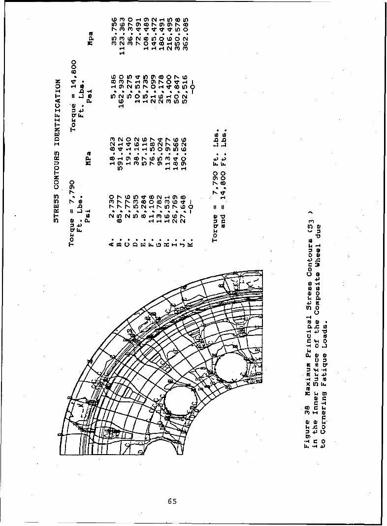
38. Maximum Principle 5tress Contours (53) in the 65Inner Surface of the Composite Wheel due toCornering Loads
39. Von Mises Equivalent Stress Contours (Seg) in 66the Inner Surface of the Composite Wheel due toCornering Loads.
40. Normal Stress Contours (Sxx) in the Bottom 67Surface of the Composite Wheel Rim due toCornering Fatigue Loads
41. Normal Stress Contours (5yy) in the Bottom 68Surface of the Composite Wheel Rim due toCornering Fatigue Loads
42. Maximum Principle Stress Contours (33) in the 69Bottom Surface of the Composite Wheel Rim due toCornering Fatigue Loads
43. Von Mises Equivalent Stress Contours (Se9) in 70the Bottom of the Composite Wheel Rim due toCornering Fatigue Loads
44. Wheel Mold 72
45. 500 ton Hydraulic Press 76
46. Wheel with Tire Mounted 77
47. Close-up of Mounted Tire showing Wear of 78Locking Ring after 9 Demountings
8
48. Composite Wheel Mountinq and Direction of Load 80
Applications
q9. Composite Wheel Set-up for Tightening Wheel 84Nuts to Fixture Studs
50. Instrumentation of Test Fixture to Measure 84Axle Deflection Under Static Loads
51. Composite Wheel during Cornering Fatigue Test 85
52. Non-Destructive Testing of Composite Wheel 85using Accoustical Emission Methods
53. Mounting of Composite Wheel with Steel Ring 86using Conventional Clamps
54. Set-up of Stationary Deflection Test 86
55. Close-up of the Composite Wheel Mounted to the 87Hub and Axle Cornering Fatigue Machine
56. Composite Wheel during Fatigue Test Adhesive 87Bond Between Steel Ring and Composite WheelDisc is Shearing Out
57. Steel Ring separated from Composite Wheel Disc 88due to Adhesive Failure After 3,400 FatigueCycles Under maximum Loads
58. Close-up of Adhesive Resin Separation after 88Completion of the Fatigue Test
59. Test Set-up for Indoor Endurance Test 90
60. Sample B After Test was Stopped due to Fatal 92Cracking
61. Sample A After Failure Showing Location of 94Pieces Broken Off
62. Sample A After Failure Showing Damaged Section 95
63. Sample A After Failure Showing Section where 96Tire Started to Separate from Composite Wheel
64. Sample A After Failure showing Overall View of 97Tire and Rim Assembly

6 5. Loclinq Rinq after Failure 93
66. Cross-5ection of Locking Rinq 99
67. Cros.s Section of Wheel i00
10

1.0 INTRODUCTION
The U.5. Army Tank-Automotive Command has been interestedin improving tactical truck life and performance. Thisstudy addressed the problems posed by the M809 and M939series 5 ton trucks.
Current truck wheels and frames, which are manufacturedfrom conventional materials (primarily steel), exhibitexcessive deterioration from corrosion while in service.In order to improve performance in this area and todecrease the overall weight of the vehicle, a fewcomponents were selected for conversion to structuralcomposites. This program involves the conversion of atruck wheel from steel to structural composite and theevaluation of these new wheels in the military environment.
Ewald Associates, Inc. considered the most significantvariables in the redesign of the current wheels from steelto structural composite materials. These materials havean organic chemical matrix, such as epoxy or vinylester,into which reinforcing fibers such as glass, graphite oraramid are disposed. By proper combination of fibers andmatrix, composite wheels can be manufactured to withstand thesevere environment in which military vehicles operate. Thedeveloped composite wheel proved to be much lighter thanits steel counterpart, just as strong if not stronger, morecorrosion resistant, and can be manufactured using existingprocess techniques with some modification for product qualitycontrol.
Structural composites, however, are anisotropic in theirproperties, thus their design requires more complex procedures.These procedures require the use of sophisticated computerprograms and are usually based on finite element analysistechniques.
In addition to design and material selection, manufacturingmethods must be analyzed and proper measures taken toensure strict quality controls to achieve the strength,stiffness, toughness and durability required'in the partselected.
11

2.0 WHEEL DESIGN AND ENGINEERING
2.1 Wheel Design
The design of the composite wheel was based on compressionmolding as the manufacturing process. Both the basic wheeland the retaining ring were to be manufactured using thismethod.
The initial wheel design, in addition to being thicker incross-section, employed metal inserts in the mounting holesto withstand the bolt torque. This design was retained untiltesting showed that a metal retaining ring was requiredinstead of metal inserts.
The wheel assembly was designed to maintain the overall sizeof the current steel part. The following constraints wereused in this design:
2.1.1. Ten equally spaced mounting holes 1.210 to 1.220inches (30.734 to 30.988 mm) in diameter were molded intothe wheel.
2.1.2. The disc and wheel rim were fabricated as anintegral assembly. Thus, no rivets were necessary forattaching the two components as is the case with thecurrent steel wheel. A schematic of the developedcomposite wheel is shown in Figure 1.
2.1.3. Variable thickness cross sections were usedto minimize stress concentrations at critical loadcarrying sections and to allow for a uniform fiberflow during the molding process.
2.1.4. The wheel rim was within all of the Armyrequirements, i.e. the maximum out of round and themaximum out of flat are both less than 1/16 inch(1.5875 mm).
2.2 Design Approach
The following design approach was followed during the courseof the program:
2.2.1. Basic characteristics of the current steel wheelwere determined from field data, data supplied by TACOM,and geometric measurments taken from the existing fleet.
12

SEPARATE SIDE RINGFOR TIRE MOUNTING
INTEGRATED RIM/DISC
UIT
-- '825. 01 .
t3 1V!6.729
Pf LOT- 01A4
ro • .87
I *G.81Z_
Figure 1 Composite Wheel Assembly (20 x 7.5 In. Wheel)
13

2.2.2. The input loads on each wheel were evaluatedbased on the Society of Automotive Engineering (SAE)recommended practices.
2.2.3. Based on load data generated for the steel wheel,various composite wheel designs were investigated. Thecomposite wheel design was based on a symmetricallyvariable cross-section. This concept aids in minimizingstress concentrations at critical load carrying sections.
2.2.4. A computer model was developed as an aid in theinitial stages of the conceptual designs. This isdiscussed at a later point in this report.
2.2.5. After several initial designs were completed, acomplete finite element program was developed and used todetermine stress contours in the selected design of thecomposite plastic wheel under the applied loads suppliedby TACOM.
2.2.6. The optimum composite material for the wheelapplication was introduced in the analysis.
2.2.7. Computer output of the various stress contours inevery composite lamina were plotted using the NISA program.Details of the analysis are discussed in section 5.
2.2.8. Readjustment of the wheel thickness was made,based on the computer output and the failure criterionfor selected composite laminates. The analysis usedthe maximum stress theory as the failure criterion.Any local area of high stresses was increased inthickness to allow for a safety factor of at least two.
2.3 Wheel Concept
This concept of variable thickness resulted in a functionalcomposite wheel with minimum weight. This is in contrast tostamped metal wheels where the rim and disk are fabricatedby stamping steel sheets of specified thickness.
3.0. DESIGN REQUIREMENTS
The composite wheel design was dictated by the applied loadsencountered during the service life of the truck.These loads are numerous and were thoroughly investigated.Some of the load requirements are discussed below.
14

3.1 Input Loads
The input loads for the wheel design were based on dataestablished by Army specifications and SAE recommendedpractice. These loads can be classified according to thefollowing requirements the wheel must be able to meet duringthe truck service life.
3.1.1. Dynamic Cornering Fatigue Test (Figure 2).The applied force and moment on the wheel were definedas:
M = L[(slr)u=dl12 F= M
Moment Arm
F = Force (ibs)
Where M = Bending moment as applied on the truck wheel(lbs-ft)
L = Load rating of the wheel as specified by Armyrequirements (LB force) = 5190 LB (2354.2 Kqor 23086 Newton)
slr = Static load radius of the tire to be used on thewheel as specififed by the army (inches) = 20.3 IN(515.62 mm)
u = Coefficient of friction developed between tireand road (=0.70)
d = Offset of wheel = 3.75 inches (95.25 mm)
K = Nondimensional parameter (1.10 to 1.33) = 1.33
The wheel was designed to survive at least 500,000 cyclesunder these loads without failure.
The wheel should be able to sustain these loads for thisnumber of cycles without the developing cracks thatpropagate through any of the wheel sections.
15

TEST LOAD
M6OMENTARM
(30IN( 762 wý)uýl-.
D ISH
(POSiITVE SHOWN)
Figure 2 Application of Load During Cornering Fatigue Tests
16

3.1.2. Rim Dynamic Radial Fatigue Test (Figure 3).The radial load applied to the wheel was determinedas follows:
F = LKr
Where F = Radial force (LB force)r
L = Load rating of the wheel as specified by the Army5190 pounds.
K = Nondimensional parameter (=2.0)
3.2 Minimum Design cycle life
The mimimum design cycle life for the fabricated compositewheel was 60,000 cycles.
Based on the above requirements, the various composite wheeldesign concepts were reduced to one optimum design. In thisconcept the wheel cross-sections remained symmetric. This isthe basic cross-section shown in Figure 1. The variables ineach concept were primarily wall thickness, distribution ofreinforcing ribs, and the number of ribs. During this phaseof the development, these parameters were varied to producea wheel of minimum weight which would withstand the loadsimposed during service.
4.0 FINAL DESIGN CONCEPT
The final design concept for the composite wheel is shownin Figure 4. The average wall thickness is approximately0.75 INCHES (19 mm). Reinforcing ribs (20 ribs at equalintervals around the circumference) were added to providea uniform load carrying capacity at minimum weight.
4.1 External Dimensions
The external dimensions of the composite wheel were dictatedby tire size, location of mounting bolts, and rim diameter.The build up in the plastic wheel thickness was accommodatedon the inside of the wheel as shown in Figure 4. No sharpcorners between the rim and the disc were permitted. Thiswill allow a gradual transition of the stresses from the discto the rim, thus eliminating areas of stress concentrationand probable initiation of cracks.
17

Tire Mounted on TestWheel " " "
Q Driving
:Load Wheel"
/ Cooler
Figure 3 Applied Loads on Wheel During Rim
Radial Fatigue Testing
18

S~7.50"SEPARATE SIDE RINGFOR TIRE MOUNTING
INTEGRATED RIM/
DISC UNIT
RIB(20 equally spacedribs)
20.0 DIA.
8.725 8.25" DIA.8.729 B.C.
PILOT DIA.
6.687"
6.812
Figure 4
Composite Wheel - Final Design
19

Areas around the mounting bolts in the disc were formed fromthicker material to form bosses. These bosses were reinforcedwith steel inserts to accept the mounting bolts. This approachwas intended to decrease the stresses at the bolt mountingholes and thus avoid enlarging the mounting holes or creatinghair line cracks while in service.
4.1.2 The composite wheel design contains ten (10) mountingholes as required in the basic drawing. At first, the wheelwas designed with steel inserts to provide the necessarysurface for holding the bolts and retaining the necessarytorque. Later tests showed that with these inserts therewas insufficient material to keep the wheel from cracking.The final design uses a metal ring to provide the necessarysurface area to distribute the mounting bolt load adequately.
4.1.3 The composite wheel contains a slot three inches longby 0.26 inches wide (76.2 x 6.604 mm) to provide an openingfor the valve stem. In addition, there is a 1/2 inch (12.7 mm)hole in the dish portion of the wheel to allow the valve stemto extend through for servicing.
4.1.4 The resulting truck wheel is corrosion resistant withbetter geometrical uniformity and a significantly reducedweight. A 50% weight reduction was achieved in the compositewheel as compared to the steel wheel. Because a wheel is anunsprung and rotating mass, this weight reduction isparticularly significant with regard to truck ride, vibration,and acceleration.
4.2 Integral disc/rim assembly
4.2.1 The wheel was designed as an integral disc/rim assemblywith a separate side ring. The latter was designed as a splitcomposite side locking ring with a 0.092"-0.31" (2.38 to7.94 mm) gap and breaking slots to complement the compositewheel. This ring is essential for mounting and removal ofthe tire. The ring also provides sufficient spring force tohold the tire in place while the wheel is in service.
4.2.2 Details of the split-in ring with the breaking slotare shown in Figure 5. It should be noted that the detailsof the breaking slot and the split-in are identical to thoseused in the current steel side ring. The prime difference isis that this ring was fabricated from continuous fiberreinforced composite material.
20

ý.,4
-I,.o
-L ,I
kX0
V
"14
•.)2S
24
IZID
21

4.2.3 A view of the assembled disc/rim composite part, theassociated side ring, and a mounted tire is shown in Figure 6.
5.0 ENGINEERING ANALYSIS
The basic design of the wheel was completed and optimized.The wheel was anaylzed using finite element modeling. TheNISA computer model was used in conjunction with thick shellelements to present the wheel structure. Three dimensional(Instead of two dimensional) elements were employed, toaccurately duplicate the geometric features of the compositewheel design. Because this design is symmetric, only halfof the wheel was modeled. The concentrated stresses aroundthe mounting holes were analyzed separately. The wheel ringwas also modeled independently. Use of common nodes betweenthe ring and the wheel provided displacement continuity, andcommon stresses provided an accurate and realistic simulationof the actual structure.
5.1 Computer Analysis
Computer analysis of the plastic wheel under the aforemen-tioned loading conditions were used. The resulting stressesbetween the disc/rim joining area, between the assembly andthe attached side ring, and around the mounting holes, weredetermined. These are the most critical areas, since theyare exposed to high stresses. High stress concentrationsoccur around the mounting holes, where the truck weight istransmitted via the mounting bolts.
5.2.1 Since the composite wheel is far from a duplicationof the current steel wheel, a detailed finite element analysiswas conducted. The analysis was based on the following:
5.2.1.1 Proper composite material allowables basedon a 35 percent confidence level.
5.2.1.2 A fine mesh grid system using a two dimensionalshell element for each composite layer of thewheel section.
5.2.1.3 A specially adoptable computer program(NISA) designed for laminated compositematerials was used. This program usesfinite shell elements to model the wheel.
22

Figure 6 Assembled Composite Wheel with Tire Mounted
(Conceptual Design)
23

S.2.1.4 Since the wheel was fabricated from orientedcomposite materials, the material anisotropyand bending-extensional coupling will benecessary features in the analysis.
5.2.1.5 The use of shell elements (tailored forcomposite materials) for modeling the wheelstructure. These elements included thefollowing parameters:
5.2.1.5.1 The effect of transverse shear deformationand rotary inertia
5.2.1.5.2 Material anisotropy
5.2.1.5.3 Bending/extensional coupling due to fiberorientation
5.2.1.5.4 Other material characteristics
5.3 Finite Element Presentation of the Composite Wheel
5.3.1 Various size finite shell elements were used in thisanalysis. Very small size elements were used around themounting holes, at the rim/disc intersection, and at the sidering attachment areas. This allowed the detection of any highstress concentration, especially around the mounting bolts.
5.3.2 A typical finite element model of the composite wheelis shown in Figure 7. Due to structural and load symmetry,only one quarter of the wheel structure was modeled. Figure8 dipicts a model of the truck wheel with computer-generatedplots of stress contours.
5.3.3 To calculate the ultimate stresses of each lamina, theoverall properties of the lamina were determined usingengineering constants for an orthotropic material. Fiberorientation and basic properties of each lamina were basedon developed experimental data. The contribution of eachlamina to the overall laminate properties is a function oflamina thickness relative to overall laminate thickness. Theeffect of fiber orientation in each lamina on the engineeringconstants was determined by mathematical transformationsbased on the angle between the fibers and the globalcoordinates of the structure under investigation. Thiscoordinate relationship is shown in Figure 9.
24

Figure 7 Typical Element Model of a Classic Wheel
25

_j
LU
0 0
zUJUJ cr-i cnLu
LU m
cn
cc
26

Figure 9 Fiber Directions with Respect to GlobalAxis XY of Structural Components.
27

Thus, for a lamina with fibers orientated at a-. angle 0 withrespect to the global x axis of the structure, the followingexpressions for the lamina modulus can be obtained:
* 1 n 1 cos4 e +~ .- 2u1 2 ) Sin a Cos 2 e + Sin4 •Exx Ell G1 2 El E22
Cos4a + ( _ 2_u 21Sin2eCos2 + I Sin4ae ~ ( E+ 1 2 2 1 ) 2 24
yy G22 E2 '2
5.3.4 It was assured that the strain of each crthtrop'clarina is withir the linear range of Hook's la-, and thestresses and strains were treated as second rank tensors.
The transforpation of the stresses/strains fror one set of a),:stc another for each lawina were derived frcr the eqfilibriurof a spall elerent as shown in Figure 10.
t.3.5 Assuping a biaxial state of stressee, one can obtain
the following reLationships:
•i 6x • (Cos 2 G) +•y CSin 2 ) + txy (2 Sin 9 Cos 8)
ý22 = xx (Sin 2 e) + ,yy (Cos2G) - iy (2 Sin 9 Cos 3)
jt2 =-'xx (Sin 6 Cos 9) + (yy (Sin 8 Cos 9) + -` (COs 2 G - Sin 2 e)
5irilarly, the strains in each larina can be ex.ressed as:
l= -t (CoS28) + +yy (Sin2Q) + (Sin 0 Cos 0)
•22 = •x (Sin2 e) + -y (Cos 2 e) - (Sin 0 Cos 0)2 2 yy X
Z'= -2x (Sin 9 Cos 0) +ýyy (Sin 0 CosO) + yy (C$0 2 0 - Sin 2O)Xy xyX
Where:
611 and 11 are the lamina stress and strain along the fiberdirection (11).
22 and 622 are the lamina *tress and strains perpendicularto the fiber direction.
28

Fiber Direction
X(Global Axis).
Figure 10 Orthotropic Lamina Under Biaxial 5tresse•
29

top surface
middle squrfaccee bb co t: t = su
ttom surrace
Figure 11 Eight Node Isoparametric General Shell Finite Element
30

Y
shell elementupper surface
7 shell element
shell elementbottom surface
X, Y, Z global Cartesian coordinatesystem of the structure
-7 shell element localF 7 coordinate system
1, J, K, L element corner nodal points
Figure 12 General Shell Element and Various Coordinate Systems
31

12 and 12 are the shear stress and strains of the lamina.
= angle of orientation of the lamina with respectto the global axis of the structure.
Solving the above relations, one can obtain the lamina proper-ties in the global axis system as a function of lamina orienta-tion. Based on these relationships the ultimate elasticstrength for each lamina can be expressed.
5.3.6 A numerically integrated finite element program wasused to evaluate the stresses and strains in each compositelamina, as well as the overall deformation of the compositewheel.
5.3.6.1 The computer program is basically designed forlaminated composite structural systems. The elements areeight node isoparametric general shell finite elements asshown in Figure 11. Each shell node has its own localcoordinate system, which is defined and related to theoverall global cartesian coordinate system to the wheel.Definitions of these coordinate systems are shown in Figure12. Each finite element was represented by the middlesurface of the shell and was assigned five basic degreesof freedom as shown in Figure 13.
5.4 Computer Programs Used in this Analysis:
The following computer programs were used for the executionof this project:
5.4.1.0 NISA :Overall finite element analysis program
5.4.1.1 NISACHN :To locate coincident local normals for
general shell isoparametric elements
5.4.1.2 NISAWFR :To check maximum wavefromt
5.4.1.3 NISAMPG :To generate the coordinates of middle nodes
5.4.1.4 NISAICE :To check input data and to compute elementdistortion
5.4.1.5 DI5PLAY :An interactive isoparametric finite elementgraphics program
32

/ .0
7 / f Local Node Coordinate System
I, z ~y Layer Local Coordinate System
Degree of freedom of each node
ux, Uy, uz displacements of ziode in global cartesiancoordinate system x, y, z
el, 92 rotations about axes of node I respectively
c - angle between principel fiber direction and local
element coordinate system
Figure 13 Degrees of Freedom of Shell Element Node Points
33

S.4.1.6 DIGIT :To digitize geometrical data scaled from
the drawing
5.4.1.7 Figures 14 and 15 illustrate the above.
5.5 Computer Output
For each of the load cases analyzed in this investigation,the output from the computer program included the following:
5.5.1.0 A list of all input data
5.5.1.1 Strain energy for each element
5.5.1.2 Reaction forces at each node
5.5.1.3 Nodal displacement
5.5.1.4 Element gauss
5.5.1.5 Stresses computed and printed for principle materialdirections, i.e., parallel to and normal to thefiber direction. These stresses are:
S xxtress in fiber direction
S ystress normal to fibers
5 xyinplane shear stress
5.5.1.6 Element stress resultants
5.5.1.7 Nodal averaged stress resultants
6.0 MATERIALS
6.1 Discussion
Automotive truck wheels are complex structures subjected tosevere loads during service. In steel with a modulus of30 x 10 6 psi (206.8 GPa) in all directions, the only propertiesthat need be considered are the tensile strength and fatiguelimits. In structural compositeshowever, the modulus of thematerial is lower but, its strength may be tailored as afunction of material thickness, fiber orientation, and severalother parameters.
34

0y)r..
43
430
,-4
3
0r-w0W
353
.-,4
0
1.40
I0)
35

3,
U
4-)
-,4
c
0
05
3
0
346

6.1.2 It was realized that the material to replace the basicsteel wheel will be much thicker. In order to determine theexact arrangement of constituent materials, several thickcomposite plaques (12" x 12" x 1") were molded and cut intotest samples for experimental mechanical property determination.
At first a hybrid of glass and graphite composite plies witha resin system of either epoxy or vinylester was considered.However the hybrid system did not provide the neccessarystrength.
6.1.3 Many other materials were evaluated using choppedglass in an epoxy resin (similar in nature to SMC compoundsin epoxy system). The final material choice called fororiented continuous glass fibers. The fibers were orientedboth circumferentially and radially. The basic propertiesof the constituent materials to be used in the constructionhave been developed both experimentally and theoretically.
6.2 Material Form
The wheel assembly was fabricated using two materials.
6.2.1 Continuous unidirectional glass sheets (XMC typematerial)
6.2.2 A chopped glass fiber compound (HMC type material) withhigh glass loading (65k by weight)
The continuous glass fibers provide the added fatigue strengthneeded for the wheel environment. The discontinuous fibersaided in the formation of variable wall thickness at varioussections of the wheel.
6.3 Compound
A compound of oriented continuous glass fibers and discon-tinuous glass fibers in a vinylester matrix was utilzed inthis application. The compound was supplied in a sheet formwith the proper thickness.
6.4 Mechanical Properties
Basic mechanical properties of the discontinous glass compoundare shown in Table 1. The properties of the continuous glasscompound are shown in Table 2.
37

of1 0a,0O0 0
N OD
•00 0VW 0
000 4) If W-4 * D O
NN.05 4 0 0'4
0 0w-
010 4 K
SW U4>%P
0 c.Ia
c to > t
034
$4J
0 4 If
-4 al 4 43 0.9 G *-4 1. >. 0 .
Go W 1 J4y
"4 0
-4W40 4 -Zu lu I.'u b
u-os 38
-0
.,4J
if 0 ad 0 i 1
0 4 . 4 Z, 0d I .w- V, X OD I z
r. 0 430 0 W n -OW 0 0 M4
c op N. N k D4 0-V 4~ 0 O ' 0 0 0
".40 0Q 0 r 0) Q4 N
"M v14 00 0 0 0
LD c "4 C; 0 X Vd AD U)0L % A A
CID 0 4*' m' 4'. wl h 4' N '.4
1 8 N
wID,
0
-4
-,4
0 43 0 r4 , l ,1 -1 .0 W :
to C m M MN -'+4 44
ID -' " .' 0 0 N
g0 , , o ,.4 ,4 " .0 4.)
-4 N ID LU -* ID ID ID '- .-
.C >D 0 .' a .. 0 . 0
V • 40 A 4 3 M- 0 1 01
4- -4 .,4 -, -,f c rI ) H• : go
14 -, p :3 o 1- V m In .
cnv
a, H0-41- ) A I
-4 0 '-3 C 4)rw0o t o x x w ua 0 Go43~ A : r p Go 0 4)W 9
rO -A 0 .C 4 4 . 043 C4411 411 f- F. FC "4 tu f 14 ad V)
44 ) 0 ) D ) ~ 39~

7.0 INPUT LOADS
The following input loads were introduced in the analysis:
7.1 Vertical Loads
7.1.1 The normal vertical static load on each wheel equals3500 pounds (1587.6 Kg, or 15569 Newton)
7.1.2 The maximum vertical load rating (for the steel wheel)equals 5190 lbs. (2354.2 Kg, or 23086 Newton)
7.2 Side Loads
7.2.1 The side load normal, applied at ground level, equals1700 lbs. (771.1 Kg or 7562 Newton)
7.2.2 The maximum side load, applied at ground level, equals2595 lbs. (1177.1 Kg or 11543 Newton)
7.2.3 The area of the load resistance is equivalent to thearea of the tire in contact with the ground.
7.2.4 The maximum applied dynamic load p = M/A x g
where P = applied dynamic load (pounds)
M = Maximum applied moment (ft.-lbs)
= 13,205 ft.-lbs. (17903.6 Meter-Newton)
A = Moment Arm
g = gravity loading factor based on various roadterrains
7.3 Resulting Dynamic Load
The resulting maximum dynamic load is equivalent to 7,558pounds (33620 Newton).
These loads are based on the following:
7.3.1 Wheel load rating = 5190 pounds (2354.2 Kg or23086 Newton)
7.3.2 Coefficent of friction between tire and road M=0.70
40

7.3.3 Wheel offset = 3.75 inches (95.25 mm)
7.3.4 Static load radius of the tire = 20.3 inches(515.62 mm)
7.3.5 Truck width = 74.00 inches (1879.6 mm)
7.3.6 In this analysis, the composite material used in thewheel was assumed to be relatively homogeneous. The mechanicalproperties of this material are represented in Tables 1 and 2.
7.4 Second Loading Conditions
7.4.1 In addition, the computer program generated engineeringdata for a more severe loading condition. These loadingconditions are:
a. The truck is at its maximum gross weight of 42,500lbs. (19277.9 Kg)
b. The maximum vertical load on the front tire is 6000lbs. (2721.6 Kg or 26689.3 Newton)
c. Side load applied at the ground level of tire is2600 lbs. (1179.4 Kg or 11565.4 Newton)
d. Tire inflation pressure is 85 psi. (586 KPa)
Results of the computer analysis (in the form of stresscontours) for the second loading condition are presented inFigures 18 to 31.
7.5 Third Loading Condition
7.5.1 Computer analysis for the Dynamic Cornering Fatiguewas run using the following input:
7.5.1.1 The applied moment on the wheel is equivalent to7790 ft-lbs. (10562 Meter-Newton). This load represents thedesign load of the wheel. A lateral load equal to 4,554 lbs.(20257 Newton) was introduced in conjunction with a momentarm equal to 3.25 ft. (0.99 Meter) This combination producesthe required moment of 7790 ft-lbs.
7.5.1.2 A safety factor of 1.9 of designed load was intro-duced to the resultant moment as specified by the SAE, thusthe torque became equivalent to 14,800 ft-lbs.
41

7.5.1.3 Under this inflated torque, the wheel bogie wasscheduled to withstand 40,000 cycles.
7.5.1.4 The composite material used is the same as in theprevious example.
The stresses in the composite wheel are plotted as stresscontours throughout the surfaces of the wheel. These plotsare shown in Figures 16 - 43.
7.5.2 These computer results indicate that a composite wheelbased on this design can perform as required.
8.0 MANUFACTURING
Fabrication of composite wheels with the required degree ofroundness and dimensional accuracy requires a well controlledproduction method. During the development program, severalmanufacturing methods were investigated. Finally, thecompression molding technique was chosen because of itsreliability and adaptability to future production methods.
8.1 Tooling
After the wheel and lock rim design was completed, toolingdesign was initiated. Based on the fact that the finalmechanical properties required were quite high and thatthe wheel contours had to contain the tire, it was decidedthat each part would be manufactured by compression molding.Thus, closed die tooling was selected to achieve both themechanical properties and the wheel shape.
8.1.1 Manufacturing Tools
A specially heated steel mold was designed, based on thefinalized geometrical configuration of the composite wheel.The design and construction of the wheel mold is important,because it influences the quality, consistency, and weight ofthe finished product.
8.1.2 The mold was fabricated from tool steel. Well designedshear edges are necessary to insure proper sealing and minimumflash. Close tolerances were maintained at the shear edges toprevent material loss and to minimize flow orientation problemsduring molding. Proper heat treatment is necessary to reducemold surface abrasion caused by contact with the wheel material,and thus to extend mold life.
42
0 MNWMOifOOMMGN
t 4N
0,
Z *W %PLDVCL(0U00O00 I
) 4ar4 eq N Nt 43 W
14
W4 X
40.
koW 0A 00
-40
x4'
00'y
1430 -4-) -3
Lo> c fl)
w 0 0H
~4. 0,
-4 i M0 .10 ad.
1. w 0 L1
'00r-I43 43 W
w10 0 0140 N Q0
-4 0 0 k4
43

0 WWN0NM0WMN
D 4 N
I--I
ZOw oor'r*ýN~oooo,0 H U) M004-4NMWIPNO 4
0 -4
En u t % a f a % a -h ft t
ro c-
V) .0
IV0
0)0'
=0001
43ko
z 0
*0 0
0 -30
M) z14
W 0 0kWa U3 W 0.
44 D

NNMMONMVMm oDmtoarwNwmv
oD N
0
F- ^
M~ Qm~~~~.. Di 4rW 4 430-09 0 0 -)0Sf-D' J ;0 -
Go0oý
0 O
43 M W
0.~~
043 M CC
S43 ..
0.. 0
041-
w 0. 0w
IL3 0
4-4 .0.
:1440 0
45

NOPNMLDONýV
I.. * a * * . . . a S
NNVOMONVO
F-O% NMOM0O 000O .43 0Z W zt1 0v ML t, 0 %'-4 1 :) 0 w
L) *0 9- qd r* &I a
V -- N N N I m 0
Ix 0 rW w-
En *
1.4 as.
:300 N *
4-1,
to00
to.4.) 4.
0)
43 4 Inf
M 3 4.) 0-4 O
W to1. 1to 0~ S
to4 0 IV
0 A
14
> 43
m' 0 1.
1.4 tOO00 44
w 0 to
46
04
E-.% OOOOOOONNV CZ *W qN O(k 0) vi W~n- In N 14-4 4)OHM4 oroowMN 0 r
in m~N~4~4W -- 4'14
0%
0 H
~4.)>0 0
to) 0'I
w 0 *f
4- -.4~4 C
ý4 0 w
0 0 14a,0
op 0
14 0L) 4J
47 0

0V-400N O -
oL 0W *W4 - rOw~I~-
w 0
00%.00
1W kDW
~4 3
A 0-
w 0'
0
in 0-4 a
00w.,.43 4
Lo~ C 0
C m 000 H
La 0 Ma
*0 "0
IU43I Oif
48~

0 W 0 N Mr*,0
ý N0Z -W if) (DP' MCOCO0000 1
U , 4 MMN4()D O4kDN IEn NNNVWM%-4fl)fa 1.4
ca 0 r. 4 0
r. w
0 G
to lb00
4J010 0
10
LoW *V44w *0 m0
4-) lbaEn -4 14
-4 wq ivL
113 C: (D.-4 014o w1 NO.d.r4 -4 1. 0w 0 00.10:c-l
:1 0~ I
X W~ *04
N 4 0 M
N .0.0ai-4-
w Ho0 0
49

En
=> N
Z- *w trýrM oooooool 0
W)U % % % a ft % % % % ft C t
C4 0 IV43 0
in 4-) %D
in mo-
J 0W. _4 WI
43' Go
cI >
to4 0 9
w04.) IV .3.
00c-4 -3 olt
LL -H II 0tO.4-)
Lo 0 cw9 a 0 1.
-0 to 1z0 (m 1
Aow
44 43 1.r'm 0 -.4N '0 --
:1 44 - 0
U) ;4 10 4.,4 :3 .0 -4
50

Ro 9~~~ *tJ VOO NOO-Nl NMDHD~~ rNo1w- winv-4
m ~ ~ ~ rD: U014
t0 En v00wm w 1%
rn u & %4 f & % & 1 010 4 30
44 00t04U
00"0 43W
0 1om 3'! 0
*54 .-I1 W-'4-1
Xo w *XV >
0 0 01
L) 0 4.
w 0: 0Cf0
(9 -4 0-
V4 C 4
.0 01 N 0Z 4) '14 LO
10 10
V 0 14
w 0. C o1I43 W~
CD 0)"a -.-. 4 .9 r.
51

0v m 0 r"
SN
Z ,1 00 0 V) 0 -Orf 0)-0 I
0 M W M q A 0 Aq eq V W 004*) -cC C t4t l ODI--lI, ) M 1
Ix 0 00'1- 3 O440 LO
0P 0004.) LD
4.) A6
00
-1 W
o .4J v>i 010
ID 0 10 00
ap .14 m
LL .0 j ,c
•.') .-
02-4000
w 01w
-.4 w o
In 0~ =
IV 4 .C
52

n. N
Z W -4~Dr'%MOk,,-4e40 V) m H q 4-40 0 -mm -
U 4C M N~fc~4VkDUN IEn~ U % tf t* 0
0 NrNNVW~e-4r')OM .43 0
~l m
r.0
0' 01
43.43 4 0c 010
L) 0 v L
10 00) _4 0En-4H
W.9 N t
rq 14 w
".4-) a,
rl 0 C~
:3 0* V0tRU
v431
W 0N 0.0
0 0w u 03
53
r,,M 0W fl -4 0 N W0Now-4LnoNO'NM1e
NNOPr-oNOr-ONc-4 R-4 q4N N
N
Z *W O~r'-OOOOOOOI 00HO') NVO~t0(NNOMO 4J0L) 4C MONMC~kWM~WCN 1 . 00
ut %) .* a t a 0
I-. .j *. * * * * a 4J04
c- -4
0,V
010 .. w
to I&
C3 >
0003
10 :3 4J H4
14 0')
U') -A4 M IL
W- 0
-4 OJ 4H
-.4 0 (D0 0N 14
w "-4 14 LO
10 04
10 C Q."4 4
N .0 40
Sc) w3 t
54

O NI',NNMO~N-0 0 00 00 0N)r%- M
0. N40erWr4
0-
on 0Z MLz M0N0N Lo 0o Go 0~~r'
-3 OA', f' 0
0
0 -4.0
0. 01~00
101~
00 0~
to0 U0
w 1
:3 4ND..
-A .94
0w 1-4
rnC0 .w
.94 ID 1
1:4 '4 04 -
55L

ND rqC - . ON(D()0
0 CDkD fl) )N W N iM
Z *W 00kD r%'.oDaDNIN
L) CO DVNO CO~ N zP W IM L) , * SS0
(z 0 -4 '0F- 0- W 010
0 .4. .4-) N"-404 0
0 IU
c o lb
~1 4 0 -
to> 0 L I
0 D 0L c.r.4V4 4o re 0~
Lo -4 0W.-4 10 Lo1. W.4 Lo
V2C 0 w.3 N L.4
-4 M .4
rt4.) 0 141.4 'A4 = -
914.
-.4 C.0
56

04 U)ON DOOMOM
W.4
Z a*W Uf) M N OD WN Nr' M IDDHV) rNOOONONONO0U 4C M O1-C L DVMV I
W.0 4-)I- v * * *l* * U
0
-4-- 0 Vn4314MW U0.M
> 4i.) In)100O
Lo00
001
L)0 m-40H. 4.) LO
10 01.i
143 al 0m 0 Ii
39 M --4I-
43 . 01* -1 s4 4-)
C 0 1543
04 0
Lp4)
x 0 0
X-40 LO
00a1m )-4 0 0
0 43,4.)
010
0 tr10t1
57

'• ,110i'•O N N N
J- co o~ O0000z..-W, MV N ODOOWOD M OD OD 1) .oo0
W ',04 0, D
rz 0 W 4q
0 0'
o •t'0
Sw (~ e~~c,0I..04JW
o0>
4.) >.t"OOW
c~0 0 0-
4) '0
1.4
0 0>)4-) C.
0 ' pto W ilo
• : C 4 O
58o
4 -) LI)
> -I mU4
O 0 4-I
10 0 @:3 &) 0 .
-H0 %Afl
58

0 q, NWMNN-40
CW0WON--4 N ~ N 9
o~ IIoOD0 gog
Z lqp * MNNICWMInNOt)I Swo- 11 to N W0~ O
E- 4-I In 0f~l W ~ ~V- Lu. 00
f-' 0z I-
OVNMOOVOM .0.0
cc 0 0 V4 -40 mm m43
k- 00z m l0L)o
w .0 V'OWNt-40MO'NWO0 11ii
V) al0 - d ,.4 t4-N N
14 04f .0
0 a
to 0 0
4-3 III'0LUk
rowa
544
z w003 4-)
4-) ,
59

NOV M ~'0 Nq t-4 0fI, * * . . . g . * *S
04 V lj -4UJO
00CD
o -q W0,rW)~-4M7NNN0
4c N4 NNU 43+H .
1- 0z I
a OOfNWNMOLfNOOH MV jW N N VWJJ
.3r * M vi V M LU . * . *
0 00
0 0 aU M'
En N WO N ~ 0 %4 MN Ihi NN.NNIN.NaOfMUM) 1I"
op - a. q-4 :3
w4 00 1 -.
I-I
to m-
4) L :10 124
4-) W *f
0
m a#
60

0 o0
0
Z %P41 w - -
1-4 Q...q %a m % k a a a a a
cc ILHr 0I f
H 0 -
F- 0z I--
CDIU* . . . .. * *a4 moD'.~- :~4o-MOON w4.4L4
0 N1o 00
0 0 a' C
U) N. Lo 0mmrQ0-4Lfmmom Iw A MNinMNIDOMP,-40 1111
ix 11 ~.4 aH . A a a ft a at a at&10
0) IL c- -01NNN: r oG
k 0 Lo0 V-4
0Wr.3
0
WD-4
001
40 V
-40 -3
14)
4)U,MLU 4.4-)
615

0M 0 M N 0 r- W *mTnNmvow0wN~
0
z- IIWWNV~rq
0- C- o0eq1,0mm
cc4 a*54-4C4N
E- 0
0 M eq .* V . M .0.0
0 c-4 fc4 r-4E- 00
000)
n 46NNf- Ms Oo40 V-4~ M
n1- o 9- 0 0l wf m C-4~~ SO IDw Si..a t-4'-4t-4'4NN 11
w. 0 :0 * -0
0to w
w0
4.)
4-I)
as 44 "-40 mIf 0
.- 4 -
~4I c
014
W43in 0
I 41 a.0
94 S
W)~ou 'a
62i~

fle . a . 9 . 0
NIDNOMNL WNMV
00
z 0 HV 0 0 C4 0 0 rqW I0 A-. NMIAMI~oorimo0
L) 01.
H 14E-. 0z
10c4 (Jt vi D CD0 Pr N .
0> 3c N D 0C4 M M -4 CncDLu1300o 00
0 0 1'iO
W) IS %0.. NC'mv- t mom T-4 Iw A -4OWMNWMMO 1li
64 0
00
30 F
0 034-) 8
00w10
4+) aP 4-Ifl v I$
0 1.
m L)
Go. do 0
63
mooNOV-4N0lo N
0 * * W4 m * N v *qOwmr'I0 momm~r
0
m m 0N%. 0 0 1- N
04 e- o44vm -4 N 0H .0J
H w.E-. 0z F-
W' v 0 0 V- Mt 0 1,, -1 j
0u)m- W-b 4F- 00
z (A 0
o to
k 01l'NO li
~~4)
10 0
0 ~ ~~~ 0 to **** F4- L) '0
c r
4'3
100L
001
14
4UJ
641
11 LOM0 WN OD fn 0LO 0
4-1 g-4u-t-N M M'
00
H . .e • • 0 I
IL W w4viNNM O
- 4 0
0O
z o
0' 0 * * * * *o)- -
0 •00
o 0
M N 0 N WfI- SrfW-W I
N flriD Vliii NW0 v *Wj.- H .%- .01
ID Nr4lM 0 NLV-hLo Ur- 0 40') 0140 (Ar- M uOfý O-4 CD M4N
~4) 00
140 0 N
w 0 . I,. *l * * r" 0 N w 0 -.
M- C
w 0
0
65S
w 4)
010b
0')
4-)
14ý
14 04 J4
65w_______________________do___op

0W 0 M . J N 0 M
0
Z V,* IMWMMMM0 W-410 0DMfiflh)IfNWV
H IIL:-11.l 43~)~f~~
m1 t* 4 0mw 0.
ix 0 LP -0r
o i~)%-4w0~m 0.0z 0W00'
0- 000O
o 3 4o, oG
L 0 0LlWf~41l0 lif- 10 I-) H 4
14 0
to rx
wUWV)0
4.)
4- 10
0o 0> IV j
V -4 :
WCAtn4Jap
0 w~>5
43 0II) 0U
a, c0L
66

M 0 M M C- W .t 0 0
0
z I OH 0owOmHI.D Io HO Otmmmoomwlv-U)Uoo
1-4 4
0 0z E-
o d W4 M VH4- WMM4
I- 00z m i00 0o*,aU m~
N 1W a . N0M0CJNeJOO(n N~ o I rqm')Nmmmni I111 .0 OOWMOWOMMWO fllilz If J-.4 a f
to NVrIu) vww (m vWU do W01. N r-4 W4 -4 N 0
:s 43 trry LU
14 0
X431
:3 0 0
0 C0
rot .LI 04 10
00IV0l It 0
4-) -
43 000 0.4-)
ca
~4.
67

N 0 0 VM-4 t',.M 0
0 - 0 * * * 0 N w M
00
z %r rl OM will.)~. r4w I
0~ ~ t-4 IlInIf0 m N4'-U- .4 ~ aa a aa .
nH -4 4-
E- 0
0qrNmwnmr')
o '44
I.- 00
o 0 POU O0a
w w vQ WWN 00 0 l- N0 H ucc v .4-f4 aa aa1- 0 1,:N~ 9; 11 .;
w.a 0'00
Lo aL V
0 0
0 L) -j4J
r . 4
000U 43 t
10E) U)
z 0 U4-)
-43 04
D IK-. "'4
wa *.14 cl
68

04 D WNWOMMOM
0
0
0- r- o rI~wo-NmH Q.0 4 I ,a % l,c a d mm
H 1.4)
1- 0z E
a M P-N 0 V -- Wt'% .0.01-4 o-4rLnNwwv j .
)cN -4r' M N c-4 cD 14 b4Lt-. 00z m h0
V') IL R5-4 O N orn r-, to MurýMNo~-,r4 ILu .0 , L.U0-4N '. r-0 0 if
I- ID NNNLD w-C'i.DWDN
w4 00 Q * * . I.w'
0 C
0 01
to 0~IV L *rnu..j-430 0En. E)-
*-IC
.'4 tu.
iv c
x4 0' 0C143
43 0
N 04.3Sav
~4-)
lid C -A
69

N uIu-INN N
0 r-4 N M O d*
0 w41 OWWVNMNWPOI-I I0 a a a a a A 4 a a I
E) 61.aH a jLid trliw
z E-
in if
o r4 qel94u r.
000
0) 0 INPcQ'O' OD
wi .0 OO W r- M M N il
n aaIL N~l~reJN0N 0 C:
tr L4 114 0 0
I(3 0 0
0s.1
0 0140.4
4.3
4.3 Or
P-4 La.
re IV
J '44 -,40y14 14
Le 14W E 0Lo 01L)
43 0
o *3
4.)
'4rg
-.4 nJ .9
70

8.1.3 The wheel mold consisted of three basic units:
8.1.3.1 The female cavity
8.1.3.2 The male plunger
8.1.3.3 Sliding side blocks activated by hydrauliccylinders
8.1.4 A schematic of the basic wheel mold is shown in Figure44. The tool is equipped with ejection pins activated by anejection plate for part removal from the mold.
8.1.5 Since the design requires that the disc and rim assemblybe fabricated as an integral unit, and the side ring to befabricated separately, another steel tool for the side ringwas designed and fabricated. This tool was simpler than thedisc/rim tool.
8.1.6 Tool steel was used to fabricate the side ring mold.Like the disc/rim mold, proper shear edges and core heatingare required. The same quality necessary for the disc/rimmold is also required for the side ring mold. All other tooldetails are similar to what has been discussed above.
8.1.7 The dies were tried out using various sized charges.By trial and error, the proper charge size was determined.
The ring mold was charged with HMC compound in the main cavity.These rings were tested and then changed to high strengthmolding compound (XMC). These rings had long directionalglass fibers in areas of high stress concentration.
8.2 Manufacturing Approach
To fabricate a truck wheel with the required roundness anddimensional accuracy, a highly controlled production processwas adopted. During the program, compression molding waschosen due to its flexibility and adaptability to futureproduction systems.
8.3 Manufacturing Technique
The manufacturing process for metal wheels usually involvesstamping, forging, and welding. Each of these processescan produce nonuniformities such as eccentricity and runout.Eccentricity is defined as a measure of the amount that thehub is off-center and runout is a measure of deviation of therim from a true circle.
71

MU,
•r•o
'-40
o,-4
440
r.)
.4-)
72

8.3.1 To minimize eccentricity and runout during themanufacturing process, two important parametersmust be precisely controlled. These parametersare:
8.3.1.1 Blanking of the composite laminates
8.3.1.2 Holding procedures while the composite is in themold.
8.4 Composite Laminate Blanking
The continuous glass laminates were stacked with therequired fiber orientation (as dictated by wheel design)and cut using steel templates. This ensured properfiber orientation, weight, and size of the preform.
8.4.1 The discontinuous glass reinforced sheet was blankedusing different steel templates, which are smaller than thetemplates for the continuous fiber laminates. The smallblanks of randomly oriented glass laminates flow during themolding cycle, thus eliminating air entrapment in the moldedwheels. Again the preform blank was cut to closely controlledweight and dimensional specifications.
8.4.2 The use of steel templates to cut the blanks fromcontinuous unidirectional glass compound sheet ensuredsize consistency of each blank. Furthermore, each compositecharge was weighed before placing it in the mold. The weighttolerance of the laminated composite blank was controlledto ensure specified weight tolerance of the wheel beforemolding.
8.4.3 In addition to the above procedures, use of steelmolds maintained weight control of the finished productby preventing material from escaping during the moldingprocess.
8.5 Weight Control
8.5.1 The following steps were adopted to control the weightof the plastic wheel:
8.5.1.1 The continuous unidirectional glass composite wassupplied as uncured unidirectional prepreg on a rollwith the proper width up to 48"" (1219 mm) wide.
73
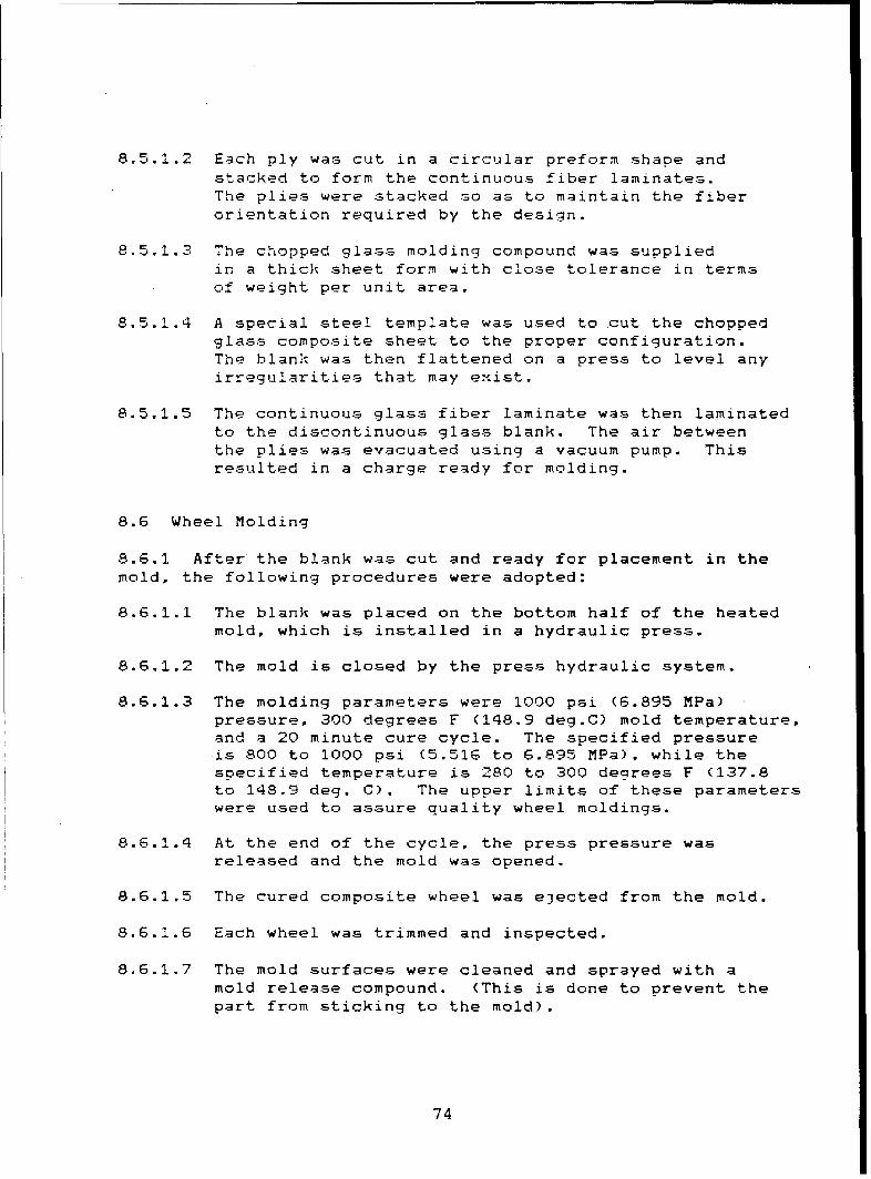
8.5.1.2 Each ply was cut in a circular preform shape andstacked to form the continuous fiber laminates.The plies were stacked so as to maintain the fiberorientation required by the design.
8.5.1.3 The chopped glass molding compound was suppliedin a thick sheet form with close tolerance in termsof weight per unit area.
8.5.1.4 A special steel template was used to cut the choppedglass composite sheet to the proper configuration.The blank was then flattened on a press to level anyirregularities that may exist.
8.5.1.5 The continuous glass fiber laminate was then laminatedto the discontinuous glass blank. The air betweenthe plies was evacuated using a vacuum pump. Thisresulted in a charge ready for molding.
8.6 Wheel Molding
8.6.1 After the blank was cut and ready for placement in themold, the following procedures were adopted:
8.6.1.1 The blank was placed on the bottom half of the heatedmold, which is installed in a hydraulic press.
8.6.1.2 The mold is closed by the press hydraulic system.
8.6.1.3 The molding parameters were 1000 psi (6.895 MPa)pressure, 300 degrees F (148.9 deg.C) mold temperature,and a 20 minute cure cycle. The specified pressureis 800 to 1000 psi (5.516 to 6.895 MPa), while thespecified temperature is 280 to 300 degrees F (137.8to 148.9 deg. C). The upper limits of these parameterswere used to assure quality wheel moldings.
8.6.1.4 At the end of the cycle, the press pressure wasreleased and the mold was opened.
8.6.1.5 The cured composite wheel was ejected from the mold.
8.6.1.6 Each wheel was trimmed and inspected.
8.6.1.7 The mold surfaces were cleaned and sprayed with amold release compound. (This is done to prevent thepart from sticking to the mold).
74

8.6.2 A photograph of the compression molding press used inthis process is shown in Figure 45.
8.7 Discussion of the Manufacturing Process
8.7.1 The first attempts at composite wheel fabricationutilized an all continuous glass compound oriented in thedesign directions (radial and circumferential). This type ofmaterial, however, did not produce consistent molded wheels.All that was learned in this phase was the charge weight wasapproximately 44 pounds(19.96 Kg). After several trials, afinal charge pattern was developed.
8.7.2 Composite wheels were manufactured using two differentglass orientations. The first group of wheels were moldedusing an equal amount of continuous and discontinuous glassreinforcement (50% XMC, 50 HMC). The second group was moldedusing a high percentage of continuous glass (XMC type material)in a circumferential and in a radial direction.
8.7.3 Preliminary Inspection of Completed Composite WheelAssembly.
Upon completion of manufacturing, a tire, tube, and flap weremounted on the plastic wheel and lock ring. The tires wereinflated to 90 psi (621 KPa). The air pressure was checkedperiodically over several months and no loss in air pressurewas noted. The lock ring also remained in place. Thiscompleted the manufacturing process. No C-scan was performed.
9.0 COMPOSITE WHEEL TESTING
9.1 Mounting and Demounting
One of the considerations in the use of composite wheels wasmounting and demounting the tire, tube and flap to and fromthe wheel. Using standard steel tools, the tire with tubeand flap was mounted to the composite wheel and demounted.The tire was inflated to approximately 95 psi (665 KPa) andheld for 30 minutes. The maximum inflation pressure achievedwas 105 psi (724 KPa). Mounting and demounting were repeatedten (10) times. No detrimental effects on the wheel wereobserved. Figure 46 is a photograph of the tire mounted onthe wheel, while Figure 47 illustrates some wear on the lockring after nine demountings.
75

Figure 45 500 Ton Hydraulic Press to be Used in
Manufacturing Leaf 5prings and Wheel Assemblies
76

Figure 46 Wheel with Tire Mounted
77

Figure 47 Close-up of Mounted Tire Showing Wear on Lock Ring
after nine demounting~s
78

9.2 Testing at Budd Wheel
Composite Wheels previously described were subjected to testingat the facilities of the Budd Company located in Detroit,Michigan. In order to determine whether these wheels wouldperform as well as the basic steel wheel, they were subjectedto the Dynamic Radial Fatigue Test in accordance with theprocedure described in SAE J267A. The first test conductedwas the dynamic cornering fatigue test. In this test a selectedaxial load was applied to the hub and lug bolt while spinningthe wheel rim at a constant rate. The axial load was appliedto provide a bending moment to simulate the loading conditionencountered during vehicle cornering.
The wheel was mounted to a rotating mounting plate to whichthe rim flange was securely clamped. The composite wheel wasfastened to the test hub by bolts and ten flat-faced nuts witha bearing area 1 11/16 inches (42.86 mm) in diameter. Thewheel nuts were tightened to the hub with a torque equal to450 ft-lbs. (610 Meter-Newton). The test hub was bolted toa horizontal load shaft as shown in Figure 48.
9.2.1 Load vs. deflection was determined for wheel #1 andwheel #2.
Data is shown in Tablev 3 and 4.
9.2.2 The clamped composite wheel without any applied loadwas within the specified eccentricity of 0.010" (0.254 mm)normal to the point of loading. The applied load wasmaintained at a nominal angle of 40 degrees from a planethrough the center of the rim. The test loads were appliedin increments of 1,000 lbs. (4448 Newtons) up to the maximumcapacity of the testing machine (14,000 lbs., or 62,275Newtons). The applied load and the deflection of the shaftwere monitered and measured after each load increment. Themaximum static deflection of the shaft for wheel #1 reached0.237 inch (6.02 mm) at 14,000 lbs. The load was thendecreased gradually back to 0 and the deflection of theshaft was again monitored. The static test Data of this wheelis shown in Table 3. No permanent deformation or deflectionwas noticed during the test.
9.2.3 The composite wheel was then subjected to the maximumload of 14,000 lbs., and the cornering fatigue test started.The load was applied with a moment arm of 39", thus, a bendingmoment of 45,500 ft.-lbs. (61690 meter- Newton) was applied
79

0
ID
i ocl0
0.
S V
I'.7|
0
J,-4)U
I "4o
i ~"4
800

TABLE #3
Static load-deflection Readings of Composite Wheel #1
LOAD APPLIED DEFLECTION UP DEFLECTION DOWN
POUNDS INCHES INCHES
700 Zeroed out 0.018
1700 0.021-0.018-0.019 *
2700 0.038-0.033-0.035
3700 0.067-0.06-0.055
4700 0.087-0.084-0.087
5700 0.104-0.100 First Jump
6700 0.119-0.119 Started over
7700 0.136-0.136
8700 0.151-0.156
9700 0.167-0.175
10700 0.181-0.193
11700 0.196-0.212
12700 0.212 Second Jump
13700 0.230 Started over
14700 0.237
14000 After approximetely 2 minutes 0.244
*No readings were taken 9oing down except for the one at the 700.
81

TABLE #4
Static load-deflection Readings of Composite Wheel #2
LOAD APPLIED DEFLECTION UP DEFLECTION DOWNPOUNDS INCHES INCHES
700 Zeroed Out 0.004
1700 0.025 0.036
2700 0.041 0.075
3700 0.055 0.094
4700 0.068 0.108
5700 0.080 0.120
6700 0.108 0.134
7700 0.125 0.14?
8700 0.135 0.155
9700 0.146 0.164
10700 0.158 0.174
11700 0.170 0.184
12700 0.180 0.193
13700 0.194, 0.201
14000 0.206
14000 After approximately 2 minutes 0.210
82

during the entire test. The test continued until a measured
deflection of 0.020 inches (0.508 mm) was detected. Thisdeflection occurred after 340 revolutions. The testing machineautomatically stopped. The setting was redjusted to allow axle
deflection up to 0.060 inches (1.524 mm) and the test startedagain. After several revolutions, this deflection was reachedand the testing machine automatically stopped. Although therewas no visible failure of the composite wheel, the capabilityof the machine could not allow any higher deflection whilemaintaining the maximum bending moment on the wheel.
Thus, the test was terminated. The plastic wheel was dismountedfrom the machine and examined.
Details of the composite wheel mounting and testing are shownin Figures 49 to 58.
9.2.4.1 Examination of the composite wheel, revealed severallong cracks extending between the mounting bushings. Othercracks were also evident through the disc area of the wheel.
9.2.5 The following observations were reported:
9.2.5.1 The wheel had moderate cracks on the inner and outersurfaces, but none appeared to penetrate the complete discsection.
9.2.5.2 The initial torque on the 10 wheel nuts dropped byan average of 110 ft.-lbs.(149 meter-Newtons) per nut. Thiscondition could have had a significant effect on the deflectiondisplayed during the test.
9.3 FATIGUE TEST - COMPOSITE WHEEL #2
The exact procedures as outlined above were followed in testingthis wheel. The wheel was attached to the wheel hub by meansof 10 ball seating nuts, the same type as currently used onsteel wheels. Each nut was torqued at 350 ft.-lbs.(475 meter-Newton). The test was conducted in the same manner, accordingto SAE J267A.
9.3.1 The wheel was subjected to the 14,000 lbs. axial loadand rotated until a deflection of .020" was detected. Thisdeflection occurred after 1,440 revolutions. Upon increasingthe allowable deflection on the machine to 0.060 inch, thewheel testing continued. The 3,200 test cycles were accumulatedwhen the 0.060 inch deflection limit was reached. At thispoint, the test was discontinued. The wheel was dismountedand examined for visible cracks or evidence of failure.
83

Composite Wheel Set Up for TighteningWheel Nuts to Fixture Studs (Wheel #3).
Figure 49
Instrumentation of Test Fixture to MeasureAxle Deflection Under Static Loads (Wheel #3)
Figure 50
84

Composite Wheel During Cornering FatigueTest Wheel #3).
Figure 51
Non-Destructive Testing of Composite Wheel Usingaccoustical Emmission methods (Wheel #1)
Figure 52
85

Mlountinq of Composite Wheel with Steel RingUsing Conventional Clamps (Wheel #1)
Figure 53
Set-Up of Stationary Deflection Test andInstrumentation of Plastic Wheel for measuringTorque versus Deflection (Wheel #1)
Figure 54
86

Close-Up of the Composite Wheel Mounted tothe Hub and Axle of Cornering Fatigue TestingMachine.
Figure 55
Composite Wheel During Fatigue Test, AdhesiveBond between Steel Ring and Composite WheelDisc Shearing Out.
Figure 56
87

Steel Ring 5eperated from Composite Wheel Discdue to Adhesive Failure after 3,400 FatigueCycle under Maximum Loads.
Figure 57
4
Close-Up of Adhesive Resin 5eparation afterCompletion of the Fatigue Test.
Figure 58
88

9.3.2 The following observations were reported:
9.3.2.1 The wheel had small cracks on the inner and outersurfaces of the disc. The size of these cracks was smallerthan those experienced in the first wheel. None of the crackspenetrated through the disc section.
9.3.2.2 There was a significant drop in the initially appliedtorque on the attaching nuts. This drop in torque allowed theexcessive deflection of the disc and the consequent need tostop the test.
9.3.3 It appears that the mounting system adapted for thesecond wheel exhibited more rigidity, and reduced crackingand deformation of this wheel. Wheels with inserted bushingsexhibited a significant number of cracks that propagatedthroughout the section of the wheel disc. Further testingwas conducted modifying the type of steel reinforcementattached to the wheel hub. Spring steel discs with a thicknessof .020" or slightly thicker was fabricated and attached tothe composite wheels.
9.a.4 It is important to note that the design load of thiscomposite wheel was based on 5,200 pounds (2359 Kg or 23131Newtons) load. A safety factor of about 2.7 was appliedresulting in an applied load of 14,000 pounds (6350 Kg or62275 Newton) during the initial phase of this testing. Therecommended practice of the SAE test procedures requires afactor of 1.9. This will require a maximum test load of9,880 pounds (43948 Newtons). These modifications were adoptedduring the next phase of testing.
9.4 Endurance Test (NIL SPEC T-12459D)
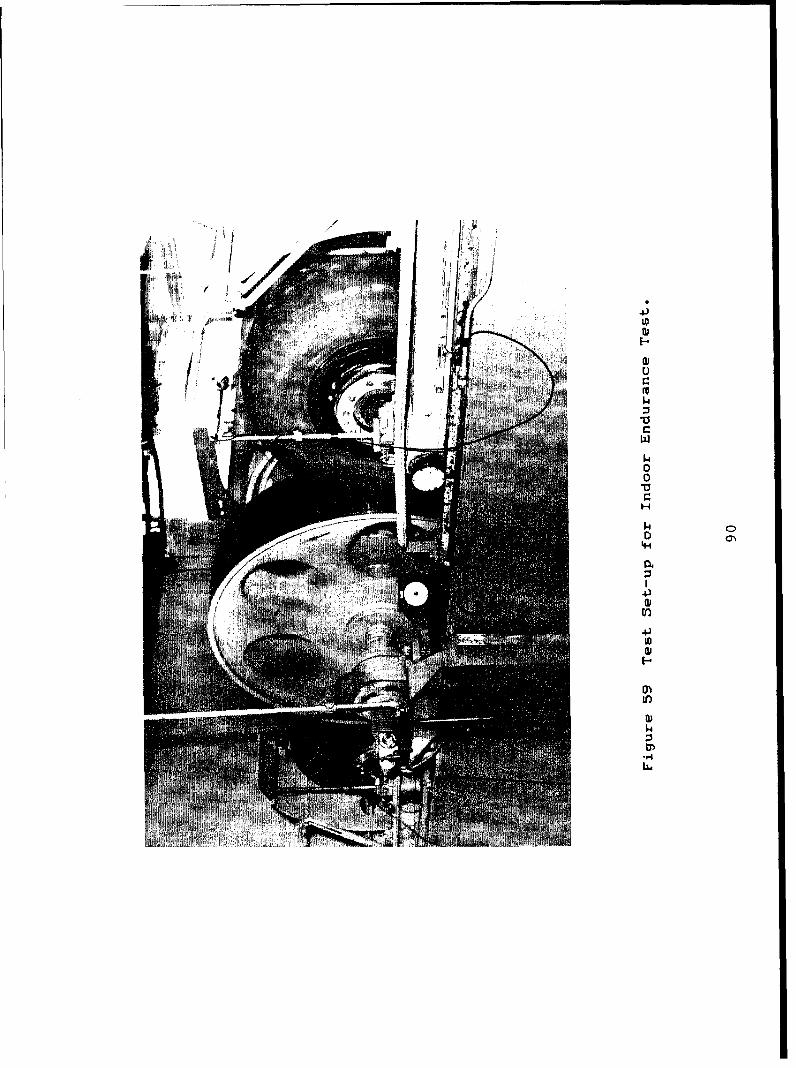
9.4.1 Upon completion of dynamic radial fatigue testing,further dynamic testing was performed on the National Bureauof Standards Test Machine to determine whether the wheelscould perform in the indoor endurance test of MilitarySpecifications MIL-T-12459D dated 31 December 1979. The tiresused were 1100 X 20 NDCC 12 ply. Four wheels were prepared.The tires were inflated to 85 psi (586 KPa) cold. The testsetup is as shown in Figure 59.
89
4;
wI-.
ID
C,
1.4
1.400V
'-4
1.4
o
4)ill
4)wIDI-
ID1.4

The test requirements were as follows:
Wheel speed 30 MPU (48.3 Km/hr)
Wheel Load Time
Pounds Newtons Hours
3645 25.131 74690 32.336 166160 42.472 24
Test Temperature = 99 degrees F (37.2 deq.C)
Wheel to axle bolts were tightened to 100 ft-lbs. (136 meter-Newton).
Metal rings were used on both sides of the composite wheelfor mounting purposes.
9.4.2 Test results were as follows:
9.4.2.1 Tire air pressure climbed and held at 94 psi.(648 KPa)
9.4.2.2 The wheel surface temperature increased to 115 degreesF (46.1 deg C) and 130 degrees F (54.4 deg C) was recordedbetween tire and wheel via a gap in the side ring.
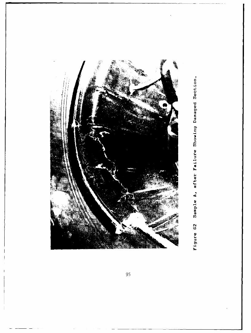
9.4.2.3 Composite wheel sample A endured for 11 hours, thendisintegrated into several pieces allowing the tire bead toslip over the wheel, causing the tube to be punctured. Themachine automatically disengaged at this point. (see Figures61 thru 64).
9.4.3 Another composite wheel was tested using the sameprocedures outlined above. This wheel (sample B) enduredthe load for 21 hours, 30 minutes. then was shut downmanually. The test was stopped due to several cracks in thewheel surface (see figure 60).
9.4.4 5ample #7 ran 7 hours at 3645 lb. (70% single tireload), and 4 hours, 42 minutes at 4690 lb. (90% single tireload). At this time the wheel lock ring blew apart, shatteredinto several pieces and punctured the inner tube. The testwas then halted.
9.4.5 5ample #4 ran 7 hours at 3645 lbs. 16 hours at 4690 lbs.,and 8 hours at 5330 lbs (1I0O single tire load). The testwas then stopped because of several cracks in the wheel andlock ring, which created a serious safety hazard. All testingfor samples #4 and #7 was conducted at 30 MPH.
91

~~hi44
043
4-)
ap43
CLi
0
14.
0
46

On samples 4 and 7, locking rings from samples A and B wereused.
Upon stopping the tests, the wheels were examined. Many crackswere noted. Both of the wheels cracked and broke out at thelip. See figures 61 and 64 for the cracking.
9.4.5.1 The failed locking ring was sectioned and examined.(Figures 65 and 66) The failure occurred under the tire beadwhere the fracture was completely through the cross sectionof the ring. This caused a section to break out, with theremaining section puncturing the inner tube. Lack of adhesionbetween the resin system and the directional fibers appearsto be the cause of the failure. In addition, the sectionedring reveals some minor porosity at the interface between thecontinous and discontinuous glass compound.
9.4.6 The tested wheels were examined using the followingtechniques:
9.4.6.1 Visual examination - inspection, using intense lightand magnifying glasses.
9.4.6.2 X-ray examination
9.4.6.3 Photographic inspection of sectioned wheels
9.4.7 These inspections revealed the following:
9.4.7.1 Some cracks were observed in the tested wheels.
9.4.7.2 No discontinuity or major separation in the resinmatrix could be detected.
9.4.7.3 Some voids were scattered throughout the wheelcross section, especially in the hub area.(Figure 67)
9.4.7.4 Some of the continuous reinforcing fibers were kinkedand wavy. (This was attributed to the design of the mold).This phenomena called "marcelling", was a major cause of thefailure of the composite wheels during testing.
93

0
to6
wua#.14
0
".4
0
-3
-4
4.4
EE4-
m -4
(AD
a,
ro
ra
95i

X 3
0,
0
al,-4.
mm0
-.4
'L)
96.

re
*4.4
~j~a> »j aa10
w'
04
<~ -H
-0
InWaa~K a~ a~*~ SD
w'
~k LL,
m o
n <
1.4
97

-7i
N. IL.I..I
$4J
'4-4
0f
LO
<0V

Figure 66 Cross-5ection of Locking Ring
99

0)
ý4-
100

10.0 CONCLUSIONS
10.1. Wheels can be made from structural composites.
10.2. Manufacturing procedures for the wheel must be revisedto prevent marcelling.
10.3. The resin system requires improvement to preventdelamination in the spinning load.
10.4. The design criteria are adequate.
101

11.0 RECOMMENDATIONS
11.1 The method of manufacturing must be improved or berestructured to prevent marcelling.
11.2 More testing must be done prior to quantity production.
11.3 Non-destructive techniques should be applied throughoutthe manufacturing process.
102

Distributio--.Lis-t
S9Copies
DEFENSE TECHNICAL INFORMATION CENTER 12ATTN: DTIC-CTACameron StationAlexandria, VA 22314
CommanderUS ARMY MATERIAL DEVELOPMENT AND READINESS COMMANDATTN: DRCMT5001 Eisenhower AvenueAlexandria, VA 22333
DirectorUS ARMY MATERIALS AND MECHANICS RESEARCH CENTER 2ATTN: DRXMR-SCWatertown, MA 02172
PLASTECPicatinny ArsenalDover, NJ 07801
CommanderUS ARMY TACOMATTN: -DRSTA-TSL 3
DRSTA-R 1DRSTA-NS 1DRSTA-RCKM 1DRSTA-G 1DRSTA-RSC 2
Warren, MI 48090
HQ, DEPT OF THE ARMY 1Deputy Chief of Staff for Research, Development and
AcquisitionATTN: DAMA-ARZ-EWashington, DC 20310
EXXON ENTERPRISES MATERIALS DIVISION 2PO Drawer HGreer, SC 29651
EWALD ASSOC, INC 119450 FitzpatrickDetroit, MI 48276
103

Copies
CIBA-GEIGYRiggs Engineering Dept8245 A Ramson RoadSan Diego, CA 92111
UNIVERSITY OF WYOMING
ATTN: D.F. AdamsRm 259, College of Engr
Laramie, WY 82071
NAVAL MATERIAL COMMANDCode (MAT0424)Washington, DC 20360
104