design and evaluation of an embedded real-time micro-kernel
TRANSCRIPT

Design and Evaluation of an Embedded Real-time
Micro-kernel
Kuljeet Singh
Thesis submitted to the Faculty of the Virginia Polytechnic Institute and State University
In partial fulfillment of the requirements for the degree of
Master of Science
in Computer Science and Applications
Dr. Stephen H. Edwards, Chair
Dr. Sallie Henry Dr. Binoy Ravindran
October 2002 Blacksburg, Virginia
Keywords: Operating System, Embedded Software, Real-time, Micro-kernel
Copyright 2002, Kuljeet Singh

Design and Evaluation of an Embedded Real-time Micro-kernel
Kuljeet Singh
(ABSTRACT)
This thesis presents the design and evaluation of an operating system kernel specially designed for dataflow software. Dataflow is a style of software architecture that is well suited for control and �signal flow� applications. This architecture involves many small processes and lots of inter-process communication, which impose too much overhead on traditional RTOSes. This thesis describes design and implementation of the Dataflow Architecture Real-time Kernel (DARK). DARK is a reconfigurable, multithreaded and preemptive operating system kernel that introduces a special data-driven scheduling strategy for dataflow applications. It uses the underlying hardware for high-speed context switching between the kernel and applications, which is five times faster than the ordinary context switch. The features of the kernel can be configured according to performance requirements without change to the applications. Along with the performance evaluation of DARK, the performance comparison results of DARK with two commercial RTOSes: MicroC/OS-II and Analog Devices VDK++ are also provided. This work was supported primarily by the Office of Naval Research under Award Number N00015-01-1-0954 and the ERC Program of the National Science Foundation under Award Number EEC-9731677.

iii
Acknowledgements This research would not have been possible without the support of many people. First and foremost, I would like to thank my thesis advisor Dr. Stephen H. Edwards for guiding me through my thesis and providing financial support throughout the process. Dr. Edwards provided me the insight to tackle different problems, read several drafts of the thesis and made invaluable comments. He has been a wonderful advisor and every graduate student should wish for an advisor like him. I would also like to thank my thesis committee members for their feedback and advice for my work. Dr. Binoy Ravindran provided suggestions concerning the real-time characteristics of the kernel. Dr. Sallie Henry gave numerous pointers to the research in dataflow. I am grateful to all members of the PEBB group for providing me their support during my research. I would like to thank Jinghong for her help in the research. She helped me in getting acquainted with the project in addition to providing invaluable support during the development of the kernel. I thank Dr. Dushan Boroyevich and Jerry for answering my questions about the hardware design and giving suggestions. I am greatly indebted to my parents for their support and encouragement over the years. I would not have been able to make it this far without their support. Kuljeet Singh

iv
Contents 1 Introduction 1 1.1 Dataflow Architecture������������������� 1 1.2 Problem Statement��������������������. 2 1.3 Research Contributions������������������.. 3 1.4 Organization of Thesis������������������... 3 2 Background Research 4 2.1 Dataflow Architecture������������������� 4 2.1.1 Dataflow Computational Model������������.. 5 2.1.2 Dataflow and Multithreaded Execution���������.. 5 2.1.3 Dataflow in Signal Processing������������� 6 2.1.4 Synchronous Dataflow���������������� 7 2.1.5 Dataflow and Power Electronics Building Blocks�����. 9 2.1.5.1 Elementary Control Object�����������. 9 2.1.5.2 ECO-Dataflow Architecture����������� 10 2.2 Real-time Kernels��������������������... 10 2.2.1 Polled Loop Systems����������������.. 11 2.2.1.1 Polled Loop with Interrupts����������� 11 2.2.2 Phase/State-driven Code��������������� 12 2.2.3 Coroutines��������������������.. 12 2.2.4 Interrupt Driven Systems��������������... 13 2.2.4.1 Round-Robin Systems������������� 13 2.2.4.2 Preemptive Priority Systems����������.. 14 2.2.4.3 Hybrid Systems���������������.. 14 2.2.5 Foreground/Background Systems�����������.. 14 2.2.6 Full-featured Real-time Operating Systems�������... 15 2.2.6.1 Task-Control Block Model�����������. 15 2.2.6.1.1 The Model�������������.. 15 2.2.6.1.2 Task States�������������.. 16 2.2.6.1.3 Task Management����������.. 16 2.3 POSIX������������������������� 17 2.4 A Survey on Real-time Kernels���������������. 18 2.4.1 Commercial Kernels����������������.. 18 2.4.1.1 MicroC/OS-II����������������. 18 2.4.1.2 Analog Devices-VDK++������������ 19 2.4.1.3 VSPWorks�����������������.. 19 2.4.1.4 QNX�������������������... 20 2.4.2 Research Kernels������������������ 21 2.4.2.1 YARTOS������������������ 21 2.4.2.2 EMERALDS����������������.. 22

v
3 Kernel Architecture 23 3.1 Requirements����������������������.. 23 3.2 Dataflow Architecture Real-time Kernel�����������.. 24 3.3 DARK Architecture�������������������... 25 3.3.1 Kernel Components����������������... 25 3.3.1.1 Threads������������������.. 25 3.3.1.2 Data-Channels���������������... 27 3.3.2 Kernel Features������������������. 28 3.3.2.1 Scheduling�����������������. 28 3.3.2.2 Thread Management�������������.. 29 3.3.2.3 High Speed Context Switching���������. 30 3.3.2.4 Time Management��������������. 31 3.3.2.5 Interrupt Handling��������������. 32 3.3.2.6 Mutual Exclusion��������������.. 32 3.3.2.7 Real-time Support�������������.� 33 3.4 DARK-Configurable Options���������������... 34 4 Kernel API 36 4.1 Inter-ECO Communication����������������... 36 4.1.1 Write/Read Simple Data Types������������ 36 4.1.2 Write/Read Bytes�����������������. 37 4.1.2.1 Write Bytes����������������.. 37 4.1.2.2 Read bytes����������������... 38 4.1.3 Write/Read Multidimensional Arrays���������. 38 4.2 Thread Management�������������������.. 39 4.2.1 Wait to Fire�������������������. 39 4.2.2 Change Priority�����������������.. 39 4.2.3 Set Deadline������������������... 40 4.2.4 Check Deadline�����������������.. 40 4.3 Time Management��������������������. 41 4.3.1 Timed Wait to Fire���������������� 41 4.3.2 Delay���������������������. 41 4.4 Data Channel Management����������������... 41 4.4.1 Size of Data Channel��������������� 42 4.4.2 Entries in Data Channel�������������� 42 4.4.3 Bytes in Data Channel��������������.. 42 4.4.4 Available Capacity of Data Channel��������� 42 4.4.5 Empty Data Channel��������������� 43 4.5 Debugging�����������������������. 43 4.5.1 Log Message������������������ 43 4.5.2 Log Message with One Argument���������... 44 4.5.3 Log Message with Two Arguments���������. 44 4.5.4 Log Message with Three Arguments��������... 44 4.5.5 Log Message with Four Arguments���������. 45

vi
5 Kernel Implementation 46 5.1 Kernel Initialization�������������������... 46 5.1.1 Configuration�����������������... 46 5.1.2 System Startup�����������������. 47 5.2 Context Switching��������������������. 50 5.3 Scheduling�����������������������. 52 5.4 Data Channel Operations�����������������.. 53 5.5 Thread Management Operations��������������... 55 5.6 Time Management Operations���������������.. 56 5.7 Interrupt Handling��������������������. 58 5.8 Real-time Support��������������������. 60 6 Dataflow Applications 62 6.1 ECO Implementation�������������������. 62 6.2 Open Loop Inverter�������������������... 64 6.3 Closed Loop Inverter�������������������. 64 6.4 Boost Rectifier���������������������... 65 7 Kernel Evaluation 67 7.1 Overview of Applications�����������������. 68 7.2 DARK Versions��������������������� 68 7.3 DARK vs. MicroC/OS-II�����������������.. 72 7.4 DARK vs. Analog Devices-VDK++�������������. 74 7.5 Summary of Results�������������������.. 75 8 Conclusions and Future Work 78 8.1 Future Work����������������������.. 79 References 80 Appendix A Code listing 84 Vita 133
vii
List of Figures Figure 1.1. A simple dataflow graph����������������� 1 Figure 2.1. Open loop control for a 3-phase inverter����������. 10 Figure 3.1. Thread control block������������������.. 26 Figure 3.2. Queue control block������������������... 27 Figure 3.3. A firing rule���������������������... 29 Figure 3.4. Thread state diagram������������������. 30 Figure 3.5. Comparison of context switching times����������� 31 Figure 5.1. Directory Structure�������������������. 47 Figure 5.2. OS Options in OS_cfg.h�����������������. 48 Figure 5.3. Dataflow Graph Representation��������������. 49 Figure 5.4. Context Switching Example���������������� 51 Figure 5.5. Segment of Write Macro Responsible for Scheduling�����... 53 Figure 5.6. Kernel Dispatcher: Pseudo-code��������������. 53 Figure 5.7. Reading from a data channel���������������.. 54 Figure 5.8. Handling channel overflow in write macro���������� 55 Figure 5.9. Wait to Fire����������������������. 56 Figure 5.10. Swap: Changing process state��������������.. 56 Figure 5.11. Timed wait to Fire������������������� 57 Figure 5.12. Delay������������������������. 57 Figure 5.13. ISR for external interrupts���������������� 59 Figure 6.1. Pseudo-code for a sample ECO��������������... 63 Figure 6.2. Process data structure������������������.. 63 Figure 6.3. Open loop control for a 3-phase inverter����������... 64 Figure 6.4. Closed loop control for a 3-phase inverter����������. 65 Figure 6.5. Closed loop control for a 3-phase boost rectifier�������� 66 Figure 7.1. Performance of DARK versions for the Open-loop Inverter application���������������������������.
69
Figure 7.2. Performance of DARK versions for the Closed-loop Inverter application���������������������������.
70
Figure 7.3. Performance of DARK versions for the Boost Rectifier application. 71 Figure 7.4. Performance comparison between Full-featured DARK with message queues and MicroC/OS-II�����������������...
73
Figure 7.5. Performance comparison between Full-featured DARK with message queues and Analog Devices-VDK++�������������.
75
Figure 7.6. Summary for results obtained while using Open-loop application� 76 Figure 7.7. Summary for results obtained while using Closed-loop application.. 76 Figure 7.8. Summary for results obtained while using Boost Rectifier application���������������������������..
77

viii
List of Tables Table 3.1. Configuration options available in DARK����������� 34
Table 4.1. API for writing simple data types to data channels or mailboxes��. 37Table 4.2. API for reading simple data types from data channels or mailboxes� 37Table 4.3. API for writing multidimensional arrays to data channels or mailboxes�.. 38Table 4.4. API for reading multidimensional arrays from data channels or mailboxes. 39 Table 7.1. Comparison of major properties of the kernels�����������. 67Table 7.2. Kernel operations per switching cycle��������������.. 68Table 7.3. Performance of DARK versions for the open loop application with message queues���������������������������..
69
Table 7.4. Performance of DARK versions for the open loop application with mailboxes������������������������������
69
Table 7.5. Performance of DARK versions for the closed loop application with message queues���������������������������..
70
Table 7.6. Performance of DARK versions for the closed loop application with mailboxes������������������������������
70
Table 7.7. Performance of DARK versions for the boost rectifier application with message queues���������������������������..
71
Table 7.8. Performance of DARK versions for the boost rectifier application with mailboxes������������������������������
71
Table 7.9. Performance comparison between Full-featured DARK with message queues and MicroC/OS-II�����������������������
73
Table 7.10. Performance comparison between Full-featured DARK with message queues and Analog Devices- VDK++�������������������
75

1
Chapter 1 Introduction Choosing an appropriate software architecture for embedded control applications can improve quality while reducing cost. Dataflow is an architectural style that supports component-oriented reusability and parallelism in software designs. Dataflow applications consist of concurrent processes that interact with each other only by asynchronous messages sent through data channels. Computation in such a design is data driven: separate threads opportunistically process incoming data as it becomes available. The complexity of dataflow designs along with the real-time and high performance requirements of control applications make an operating system necessary for these systems. 1.1 Dataflow Architecture In Dataflow [3, 8, 9, 20], a system is composed of concurrently executing processes that communicate through data channels. Dataflow designs are often depicted graphically, with nodes representing processes and arcs representing data channels, as shown in Figure 1.1.
Each dataflow process executes opportunistically, operating on incoming data as it becomes available. Because the processes share no state, know nothing about other processes in the system, and communicate only through asynchronous data transmissions along data channels, there is a high degree of independence between them. This architectural style has been proposed for use in embedded power electronics control [20]. It provides a natural fit for such control problems, where most computations can be easily phrased in terms of signal flows and value transformations. Indeed, a library of reusable dataflow processes for the power electronics control domain has also been
NODE1 NODE2 NODE3
NODE4
Figure 1.1 A simple dataflow graph

Chapter 1 Introduction
2
proposed [22]. These dataflow processes or nodes allow power electronics control applications to be developed rapidly by simply wiring together existing dataflow components. 1.2 Problem Statement To achieve concurrent (or time-sliced) execution of dataflow processes, a dataflow application requires some form of runtime supervisor or operating system to start, monitor, and manage multiple threads. Unfortunately, in the context of embedded control applications, the biggest concern associated with dataflow approaches is the additional overhead imposed by this OS layer and by time-sliced execution in general. Dataflow applications tend to have a larger number of processes or threads than applications developed using other techniques. While a larger number of independent, reusable, components makes application design easier, it can lead to an increase amount of context switching and scheduling overhead. Further, the data-driven nature of dataflow applications poses somewhat different scheduling requirements than more traditional concurrent programming techniques. If dataflow processes are awakened by every incoming data message, they may spend much of their time managing the state of their data channels and waiting for all the necessary data needed to proceed. Finally, the fact that processes only communicate via data channels implies that there are frequent (but usually small) interactions between processes along these channels. Ensuring mutually exclusive access to critical state within a data channel provides another potential for increased overhead in dataflow applications. The problem statement for the thesis can be precisely stated as- �To design and evaluate a high performance operating system kernel for dataflow applications�. The thesis describes design and implementation of a high-performance micro-kernel called the Dataflow Architecture Real-time Kernel (DARK) that specifically addresses requirements of dataflow software. DARK implements a scheduling and context switching strategy optimized for dataflow applications. Further, it can take advantage of dual-register-set hardware to drastically reduce context-switching overhead. It also provides support for dynamic priorities, �firing rules� for specifying the data channel conditions necessary for process wakeup, and typed data channels for efficient and reliable inter-process communication. The reconfigurable options provided by DARK facilitate selective removal of unneeded features to improve performance, without requiring any change to the application code. For example, the user can remove dynamic scheduling or preemptive features to meet the high-performance requirements of a particular application. In addition to DARK�s design and implementation, this thesis also contains a performance comparison of DARK against two other commercially available RTOSes using power electronics control algorithms. The results of the performance comparison indicate that the Non-preemptive DARK is more than 11% faster than non-preemptive

Chapter 1 Introduction
3
MicroC/OS-II [6], and more than 80% faster than Analog Devices� VDK++ [8], an RTOS designed specifically for the digital signal processor used in the comparison. 1.3 Research Contributions To summarize, the novel features of the operating system kernel described in this thesis are:
• A message-driven scheduling algorithm that eliminates busy waiting of dataflow threads.
• A high-speed context switching strategy that takes advantage of processors with
dual register sets.
• An interprocess synchronization technique that provides a performance boost for dataflow applications without the overhead of semaphores.
• Minimal footprint interrupt handling.
• Kernel configuration options that allow the user to selectively remove
unnecessary kernel features, reducing overhead by more than 80%. 1.4 Organization of Thesis This thesis is organized as follows. Chapter 2 provides an overview of micro-kernels and dataflow architecture. We begin by discussing the dataflow architecture before describing its use in power electronics building blocks. The strategies employed in design of real-time kernels are explained next. At the end of the chapter, a brief overview on designs of several commercial and academic micro-kernels is given. Chapter 3 describes the architecture of DARK. It explains the structures of major kernel components along with the approaches taken for scheduling, context switching, interrupt handling, etc. It also contains a description of various configuration options available in DARK. The programmer-level application-programming interface (API) is presented in Chapter 4. In Chapter 5 we discuss the complete implementation of DARK. The code for all the major operations performed by the kernel is explained in detail. Chapter 6 contains some examples of dataflow applications that are being used in power electronics control. Chapter 7 presents the results of the experimental performance comparisons. This evaluation uses power electronics control applications described in chapter 6 to assess the relative overhead of the presented design. It shows the relative performance gains achieved by reconfiguring DARK, as well as the performance comparison of DARK against two commercial kernels: MicroC/OS-II and Visual DSP++. Chapter 8 lists the conclusions drawn from the work described in previous chapters along with directions for future work. The complete source code for DARK is given in the Appendix 1.
4
Chapter 2 Background Research This chapter presents an overview of the research done in the areas of dataflow architecture and real-time operating systems. We begin by a discussion of the dataflow architecture and its applications in power electronics building blocks. The real-time kernels and strategies employed in their design are described next. Finally, we give a brief overview of popular kernels in academic and commercial domains. 2.1 Dataflow Architecture Dataflow is both a programming concept and implementation technique. A dataflow program can be represented as a directed graph (Figure 1.1), where an edge between two vertices represents the flow of data tokens between those vertices along the direction of the edge. Each vertex in the graph represents a dataflow element that can fire when there is data waiting at each of its inputs. When an element fires, it consumes one input token waiting at each input edge and may produce one or more output tokens to be sent along the output edges to other elements. Useful dataflow programs can be constructed from simple elements that perform calculations and comparisons. Dataflow programs allow for maximum concurrency because tokens flowing along different parts of the dataflow graph may proceed safely in parallel. The readers are advised that the dataflow architecture being discussed in this chapter is not related to dataflow diagrams used in software engineering. In software engineering, a data flow diagram (DFD) is used to model the system after requirements gathering. It is a graphical representation that depicts information flow and the transforms that are applied as data move from input to output [41]. A DFD is used to represent a software or system at any level of abstraction. The dataflow architecture that is being discussed in this chapter is more concrete in that it is not a high level representation, but the exact representation of processes as nodes and communication between them through data channels. The next section consists of a brief introduction to the dataflow computational model. The Sections 2.1.2 and 2.1.3 describe the impact of dataflow model in the areas of multithreaded computing and signal processing respectively. In the Section 2.1.4, we discuss the synchronous dataflow model, which is predictable and decidable, and generally used in the design of real-time systems. Section 2.1.5 has a discussion of dataflow architecture in power electronics control applications.

Chapter 2 Background Research
5
2.1.1 Dataflow Computational Model Dataflow research has been proceeding since the late 1960s. Most people have been introduced to dataflow through the work at MIT, and in particular the work of Jack Dennis [18] where dataflow program graphs were primarily used to represent and exploit the parallelism in programs. In a Dennis dataflow graph [17,18], operations are specified by actors that are enabled just when all actors that produce required data have completed their execution. The dependence relationships between pairs of actors are defined by the arcs of a graph, which maybe thought of as conveying results of an actor to successor actors, and by the firing rules, which specify exactly what data are required for an actor to fire. Such a computational model is called data-driven model because the arrival of data causes execution of an actor. An alternative approach (reflecting in a way the lazy evaluation strategy of functional programming) called demand-driven evaluation can also be adopted where the results are requested only when an actor attempts to execute. Also in the early 1970s, a rather different style of dataflow models emerged [14]. Called Kahn process networks, this model replaced actors with sequential processes. The processes communicate by sending messages along channels that conceptually consist of unbounded FIFO queues. Kahn dataflow can be viewed as a generalization of Dennis dataflow [13]. While Dennis dataflow was originally applied to computer architecture design, Kahn dataflow was used by concurrency theorists for modeling concurrent software. Multithreaded architectures, with dataflow roots, use a style of dataflow that can be viewed as having elements of both. As a computation model, the dataflow approach has had influences on many areas of computer science and engineering research. Examples include programming languages, processor design, multithreaded architectures, parallel compilation, high-level logic design, signal processing, distributed computing, programming of systolic and reconfigurable processors, and power electronics building blocks. In the following sections, we review the state of art of the dataflow computational model in multithreaded architectures and signal processing, respectively. The concluding section discusses the application of the dataflow model in power electronics control applications. 2.1.2 Dataflow and Multithreaded Execution Issues and challenges for multithreaded computer architecture suitable for use in parallel computers for general purpose computation are the subject of intensive debate. These issues and challenges depend heavily on the choice of an appropriate program execution model that will affect the programming model, the organization of the underlying system as well as the development support of complex applications onto the proposed architectures-compilers, runtime systems, and tools.

Chapter 2 Background Research
6
The dataflow model and von Neumann serial control-flow model are generally viewed as two extremes of execution models on which a spectrum of architecture models can be based. The two models are in fact not orthogonal. Starting with the operational model of a pure dataflow graph, one can easily extend the model to support von Neumann style program execution. A region of actors within a dataflow graph can be grouped together as a thread to be executed sequentially under its own private program control, while the activation and synchronization of threads are data driven. The new hybrid model is flexible in combining dataflow and control flow evaluation, as well as in exposing parallelism at a desired level. Such hybrid multithreaded models have been proposed by a number of research groups with their origins in either static dataflow or dynamic dataflow. A detailed discussion of these models is beyond the scope of this thesis. However, a number of articles have been published on multithreaded execution and architecture models with dataflow origin and can be found in a survey article by Dennis and Gao [15]. Principal projects and representative work before 1995 have been discussed in two monographs [16,40] as well as other survey articles [6]. 2.1.3 Dataflow in Signal Processing Signal processing has its intellectual roots in circuit theory. Algorithms tend to be modeled as compositions of components that conceptually operate concurrently and communicate via signals that are functions of time. The components are typically filters, which transform the input signals to construct output signals. Traditionally, the signals are continuous functions of the time continuum. Contemporary signal processing is more likely to involve discrete-time signals than continuous-time signals. Here, instead of time continuum, a discrete clock globally regulates the computation. Signals have values at the discrete clock ticks, but not in between. Multirate systems involve multiple clocks, but with clear relationships among them, so that ticks in the multiple clocks can be unambiguously associated. A fairly direct model of discrete-time systems is obtained using the synchronous/reactive principle [1,2]. In this model, a concurrent program executes in a sequence of discrete steps, which correspond to ticks of a global clock. At each clock tick, the value of each signal is obtained by solving for a fixed point of a system of equations. Some synchronous/reactive languages, notably Lustre [35,36] and Signal [38], have a dataflow flavor, in that signals are viewed as streams of values, where each value is aligned with a clock tick. However, the concurrent semantics of these languages is very different from Dennis [18,19] or Kahn [14] styles of dataflow, which are distinctly asynchronous. Whereas synchronous languages are analogous to synchronous circuits in their treatment of concurrency, Dennis and Kahn-style dataflow are analogous to self-timed circuits. The synchronous model globally orders the tokens according to a global clock. In Dennis and Kahn dataflow, by contrast, signals are streams of tokens, where the relative ordering

Chapter 2 Background Research
7
of tokens within a stream matters, but there is not necessarily any ordering of tokens across streams. Partial ordering constraints on tokens in distinct streams are imposed by the data precedence in the actors or processes [43]. The synchronous/reactive model provides an abstraction of discrete-time systems where the metric properties of time are eliminated. That is, there is no measured or even specified time interval between clock ticks. Rather, there is a sequence of clock ticks. But one key property of time is retained: its global ordering of events. Dataflow abstracts things still further by eliminating this global ordering. Streams of tokens provide a suitable abstraction for signals. Dataflow actors or Kahn processes operating on these streams provide a suitable abstraction for the components. The notion of time is lost, but the data precedences are preserved. Thus, the abstraction is more highly concurrent even than the circuit-theory roots of signals processing, since the tight coordination implied by a global ordering based on time is no longer required. Instead, only the data precedences need to be respected. 2.1.4 Synchronous Dataflow Many signal processing systems involve repeated (infinite) execution of a well-defined finite computation on an infinite stream of data. Implementations have real-time constraints and often take form of embedded software. This raises a number of issues. In particular, it is important that the schedule of actor firings be predictable in order to ensure that real-time constraints are met. It is also critical that a program never deadlocks. Because of the embedded system context, it is also important that the total memory devoted to storing unprocessed tokens be bounded. In dataflow, deadlock occurs when all actors are starved. Deadlock is equivalent to halting. For general dataflow models, it is undecidable whether a program will deadlock. It is also undecidable whether a program has an infinite execution that consumes bounded memory for storing pending tokens [26,28]. One approach, therefore, is to use a subset of dataflow where these questions are decidable. Synchronous dataflow [12], which is not synchronous in the same sense as synchronous/reactive languages, is one such decidable model. In SDF, an actor is characterized by the number of tokens that it consumes and produces on its inputs and outputs on each firing. The inputs and outputs of each actor are labeled with an integer constant. For an input, this is the number of tokens that are required on that input stream in order to fire the actor. For the outputs, it is the number of tokens that are produced by a firing. In block-diagram syntax, an arc connecting the two actors represents the flow of tokens between them. If we assume that the topology of such flows is fixed, and that the number of tokens produced and consumed by each actor is fixed, then both deadlock and bounded memory are decidable. To get an idea of how this is possible, we review the notion of balance equations [12].

Chapter 2 Background Research
8
Suppose an actor A produces N tokens on an output that is connected to actor B. Suppose further that actor B requires M tokens on its input to fire. Suppose that actor A fires fA times, and actor B fires fB times. Then the balance principle requires that fAN = fBM. One such equation can be written for each arc in an interconnection of actors. The balance principle is trivially satisfied if either fA = fB = 0 or fA = fB = ∞. A more interesting situation arises, however, if there is a bounded positive solution for fi for each actor i such that all balance equations are satisfied. In this case, there may be a finite but non-zero set of firings that achieves balance. It has been shown that for a connected dataflow graph, if the balance equations have a non-trivial solution, then they have a unique smallest positive integer solution [12]. If they have no solution, then there is no bounded memory infinite execution of the dataflow graph. If the balance equations have no non-trivial solution, then there is a simple finite algorithm that will determine whether the graph deadlocks. Thus, both the bounded memory question and the deadlock question are decidable for SDF. Hence SDF graphs can reliably be implemented in embedded real-time systems. Although the decidability of the SDF model is convenient for certain applications, it comes at a very high cost in expressiveness. In particular, the fact that the token production/consumption patterns are fixed means that an application cannot use the flow of tokens to effect control. That is, conditional variations in the flow are not allowed. Even signal processing applications involve a certain amount of conditional computation, so this restriction becomes very limiting. One solution is to broaden the dataflow model that is used by accepting the undecidability of the key propositions but nonetheless attempt to decide. Undecidability merely states that no algorithm can decide in finite time for all programs. It does not prevent us from constructing a formalism where a compiler can decide for most programs. This is the approach taken by Buck [26], who based his approach on the token flow model of Lee [11]. This model generalizes the balance equations to permit the number of tokens produced and consumed to vary dynamically. To do this, it attaches a symbolic value rather than a numerical value to each port of each actor. The balance equations therefore include symbolic coefficients, and have to be solved symbolically. Frequently, it is possible to solve them. The resulting solution can be used to construct a schedule of actor firings that is provably free from deadlocks and that requires only bounded memory for token storage. Buck�s model came to be called Boolean dataflow (BDF), although the basic concept has been extended to non-boolean control signals [27]. BDF, however, has two problems. First, because the key underlying implementation questions remain undecidable, a programming environment that depends on being able to decide is somewhat fragile. Small and seemingly innocuous changes to a program may cause the scheduling

Chapter 2 Background Research
9
algorithms to fail. Also, experience constructing programs using this model indicates that it is not often the most intuitive way to specify a computation. 2.1.5 Dataflow and Power Electronics Building Blocks Recently, dataflow has been explored for power electronics control problems in order to exploit the component-oriented reusability and inherent support for parallelism provided by this approach. It provides a natural fit for such problems, where most computations can be easily phrased in terms of signal flows and value transformations. The control of a power electronics system could be seen as composed of many basic functional blocks or Elementary Control Objects (ECOs). Dataflow is used to organize the ECOs into a run-time controller. ECO-Dataflow architecture is being used to synthesize modularized, standardized, reusable and automatic configurable power electronics systems [20]. Section 2.1.5.1 explains the concept of elementary control objects. In Section 2.1.5.2, we describe how dataflow architecture is used to combine these objects and build a control application. 2.1.5.1 Elementary Control Object A functional based approach is adopted to divide the power electronics system control into elementary control objects. An ECO is defined as [21]:
• Functionally self-contained; • Having standard interface; • Independent; • Concurrently executing; • Implemented by multiple methods.
ECO is a self-contained entity, which interacts with the outer system using well-defined inputs and outputs. An ECO doesn�t need to know about the other ECOs to which it is connected. It just takes the input, processes it and outputs the results, if any. ECOs are naturally independent, so they are able to execute concurrently for distributed control of power electronics systems. Indeed, a library of reusable ECOs for the power electronics control domain has also been proposed. They allow power electronics control applications to be developed rapidly by simply wiring together existing ECOs.
Alternatively, ECOs can also be considered as software components that replace the equivalent hardware. ECOs can be written to substitute components like modulators, regulators, etc. They are easier to design and take much less space than their hardware counterparts. Moreover, they are reusable, as a library of frequently used ECOs can be maintained. The main drawback of using these software components is their speed. They are usually much slower than the equivalent hardware components.
The condition for an ECO to execute is designated by its firing rule. A firing rule specifies the input channels on which an ECO should wait for inputs, before starting

Chapter 2 Background Research
10
execution. The purpose of ECO approach is to provide standardized and reusable building blocks to build configurable and reusable power electronics control system [21]. Dataflow architecture is used to interconnect and organize the ECOs. 2.1.5.2 ECO-Dataflow Architecture The combination of the ECO-approach and dataflow provides a component based software architecture, in which, the ECOs are treated as nodes or processes. The ECOs are connected to each other through data-channels, which correspond to arcs in the data-flow architecture. This approach introduces modularity and reusability in the design of power electronics control software. It also encourages development of control applications as a combination of self-contained and modular components. The control algorithm is represented as a Dataflow graph, which represents ECOs and data-channels using the dataflow model.
Figure 2.1 shows dataflow graph for open loop control of a three-phase inverter [20]. This application consists of seven ECOs, and it simply looks up and derives the appropriate duty cycle commands to send to each phase leg of the power stage being controlled. Every ECO in the dataflow graph has a pre-defined function and can be included in the ECO library maintained by the application programmer so that it can be reused later. 2.2 Real-time Kernels An operating system may be viewed as an organized collection of software extensions of hardware consisting of control routines for operating a computer and for providing an environment for execution of programs [34]. Other programs rely on facilities provided by the operating system to gain access to computer-system resources. Programs usually invoke services of the operating system by means of system calls. The operating system acts as an interface between users and the hardware of a computer system.
External Interrupts
Lookup_sin Lookup_sin Lookup_sin
Modulator_open
PEBB_driver PEBB_driver PEBB_driver
Figure 2.1 Open loop control for a 3-phase inverter
Chapter 2 Background Research
11
All operating systems must provide three specific functions: task scheduling, task dispatching, and intertask communication. A scheduler determines which task will run next in a multitasking system, while a dispatcher performs the necessary bookkeeping to start that task. A kernel, executive or nucleus is the smallest portion of the operating system that provides for task scheduling, dispatching, and intertask communication. In embedded systems, this essentially represents the entire real-time system, whereas in commercial real-time systems this might be all but the device drivers. There are many variants of the definition of a �kernel�. They are given below in increasing order of complexity. Of course, as the complexity decreases, so do the code size and response times.
• Nano-kernel � Simple thread-of-execution management. It essentially provides only one of the three services provided by a kernel; i.e., it provides for task dispatching.
• Micro-kernel � A nano-kernel that provides for task scheduling. • Kernel � A micro-kernel that provides for intertask synchronization and
communication via semaphores, mailboxes or other methods. • Executive � A kernel that includes privatized memory blocks, I/O services, and
other complex features. Most commercial real-time kernels are really executives. • Operating system � An executive that provides for a generalized user interface or
command processor, security, and a file management system. The following sections discuss the strategies employed in the design of real-time kernels. We start with the simplest polling-based kernels and conclude with full-featured real-time operating systems. 2.2.1 Polled Loop Systems Polled loop systems are the simplest real-time kernel. They have a single and repetitive test instruction, which is used to test a flag that indicates whether or not some event has occurred. If the event has not occurred, then the polling continues. No intertask communication or scheduling is needed because only a single task exists. 2.2.2.1 Polled Loop with Interrupts A variation on the polled loop uses a fixed clock interrupt to wait a period of time between when the flag is determined to be TRUE and when the flag is reset to FALSE. Such a system is used to treat events that exhibit a phenomenon known as switch bounce. If the system waits for sufficient amount of time after the initial triggering of the event, it can avoid interpreting the settling oscillations as events. A delay period is realized with a programmable timer that generates an interrupt after a countdown period. In the absence of such hardware, a software routine can be written to implement the delay.

Chapter 2 Background Research
12
In summary, polled loop systems are simple to write and debug, and the response time is easy to determine. They are excellent for systems where events occur at widely dispersed intervals. However, they often fail where a burst of events can occur. Furthermore, polled loops by themselves are generally not sufficient to handle complicated systems. Finally, polled loops inherently waste CPU time, especially if the event being polled occurs infrequently. 2.2.3 Phase/State-driven Code Phase-driven or state-driven code uses nested if-then statements, case statements, or a finite state automaton to break up the processing of a function into discrete code segments. The separation of processes allows each to be temporarily suspended before completion, without loss of critical data. This, in turn, facilitates multitasking via scheme such as coroutines, which will be discussed in the following section. Certain types of process lend themselves well to FSA implementation. For example, the compilation process can be regarded as comprising lexical analysis, parsing, code generation, and optimization. A process implementing compilation could be interrupted after each of the phases, but not in between. Communication programs such as network packet handlers are also often broken up into phases. Although, a phase-driven system is easier to implement, the processes that don�t lend themselves naturally to division into states are unsuitable for this technique. For more complex processes, using table-driven code is better than if-then or case statements. But, these tables can become quite large leading to errors. Finally, the manual translation process from the finite state automaton to tabular form is prone to error. 2.2.4 Coroutines Coroutines or cooperative multitasking systems require disciplined programming and an appropriate application. These types of kernels are employed in conjunction with the code driven by finite state automata. In this scheme, two or more processes are coded in the state-driven fashion discussed in Section 2.2.2, and after each phase is complete, a call is made to a central dispatcher. The dispatcher holds the program counter for a list of processes that are executed in round-robin fashion. Communication between the processes is achieved through global variables. Any data that need to be preserved between dispatches must be deposited in global variables. Coroutines are the easiest type of �fairness scheduling� that can be implemented. In addition, the processes can be written by independent parties, and the number of processes need not be known beforehand. Finally, some languages such as Ada and Modula-2 have built-in constructs for implementing coroutines.

Chapter 2 Background Research
13
On the negative side, this is an error-prone approach that requires strict discipline on the part of the programmers because it assumes that they will relinquish the CPU at regular intervals. It also requires a communication scheme involving global variables, which is undesirable. Finally, processes cannot always be broken easily into uniform size phases, which can adversely affect response time since the minimum size is a function of the longest phase. 2.2.5 Interrupt Driven Systems In interrupt driven systems, the main program is a single �jump-to-self� instruction. The various tasks in the system are scheduled via either hardware or software interrupts, whereas dispatching is performed by the interrupt-handling routines. The interrupts in an interrupt driven system may occur at fixed rates (periodically), aperiodically, or both. Tasks driven by interrupts that occur aperiodically are called sporadic tasks. Systems in which interrupts occur only at fixed frequencies are called fixed-rate systems, those with interrupts occurring sporadically are called sporadic systems, and those with interrupts occurring both at fixed frequencies and sporadically are called hybrid systems. In such systems, a snapshot of the machine-called the context-must be preserved upon switching tasks so that it can be restored upon reinitiating the interrupted process. The context includes the contents of certain registers, the program counter, and other entities that could be altered by another process. Context switching is the process of saving and restoring sufficient information for a real-time task so that it can be resumed after being interrupted. In the following subsections, we discuss examples of the fixed-rate systems, sporadic systems and hybrid systems, respectively. 2.2.5.1 Round-Robin Systems Round-robin systems are generally modeled as fixed-rate systems. In round-robin system several processes are executed sequentially to completion, often in conjunction with a cyclic executive. In round-robin systems with time slicing, each executable task is assigned a fixed-time quantum called a time slice in which to execute. A fixed-rate clock is used to initiate an interrupt at a rate corresponding to the time slice. The task executes until it completes or its execution time expires, as indicated by the clock interrupt. If the task does not execute to completion, its context must be saved. The task is then placed at the end of the executable list. The context of the next executable task in the list is restored, and it resumes execution.

Chapter 2 Background Research
14
2.2.5.2 Preemptive Priority Systems Sporadic interrupts can be use to design preemptive priority systems. A higher-priority task is said to preempt a lower-priority task if it interrupts the lower-priority task. That is, the lower-priority task is still running while the higher-priority task is about to begin. Systems that use preemption schemes instead of round-robin or first-come-first-serve scheduling are called preemptive priority systems. The priorities assigned to each interrupt are based on the urgency of the task associated with that interrupt. Prioritized interrupts can be either fixed priority or dynamic priority. Fixed-priority systems are flexible in that the task priorities cannot be changed. Dynamic-priority systems can allow the priorities of tasks to change. This feature is particularly important in certain types of threat-management systems. 2.2.5.3 Hybrid Systems Hybrid systems include interrupts that occur at both fixed rates and sporadically. The sporadic interrupts may be used to handle a critical error that requires immediate attention, and thus have highest priority. This type of system is common in embedded applications. Another type of hybrid system found in commercial operating systems is a combination of round-robin and preemptive systems, and ensures fair scheduling. In this system, tasks of higher priority can always preempt those of lower priority. However, if two or more tasks of the same priority are ready to run simultaneously, then they run in round-robin fashion. To summarize, interrupt-only systems are easy to write and typically have fast response times because process scheduling can be done via hardware. One weakness of interrupt-only systems, however, is the time wasted in the jump-to-self loop and the difficulty in providing advanced services. These services include device drivers and interfaces to multiple layered networks. Another weakness is vulnerability to malfunctions owing to timing variables, unanticipated race conditions, hardware failures, and so on. 2.2.6 Foreground/Background Systems Foreground/background systems are the most common solution for embedded applications. They involve a set of interrupt driven or real-time processes called the foreground and a collection of noninterrupt driven processes called the background. The foreground tasks run in round-robin, preemptive priority, or combination fashion. The background task is fully preemptable by any foreground task and, in a sense, represents the lowest priority task in the system.

Chapter 2 Background Research
15
Foreground/background systems represent a superset of all the other real-time solutions discussed. They typically have good response times, since they rely on hardware to perform scheduling. But foreground/background systems have at least one major drawback: interfaces to complicated devices and networks must be written. This procedure can be tedious and prone to error. In addition, these types of systems are best implemented when the number of foreground tasks is fixed and known a priori. Although languages that support dynamic allocation of memory could handle a variable number of tasks, this can be tricky. Finally, as with the interrupt-only system, the foreground/background system is vulnerable to timing variations, unanticipated race conditions, hardware failures, etc. 2.2.7 Full-featured Real-time Operating Systems The foreground/background solution can be extended into an operating system by adding additional functions such as network interfaces, complicated device drivers, and complex debugging tools. These operating systems use round-robin, preemptive priority, or a combination of both schemes to provide scheduling; the operating system represents the highest priority task, kernel, or supervisor. The task-control block model is most often used in these types of systems because the number of real-time tasks is indeterminate and dynamic. In the following section, we describe the task-control block model. We also discuss the typical states that a task may have and common ways employed by real-time operating systems for task management. 2.2.7.1 Task-Control Block Model The task-control block model is the most popular method for implementing commercial, full-featured, real-time operating systems because the number of real-time tasks can be variable. The main drawback of this model is that when a large number of tasks are created, the overhead of the scheduler can become significant. 2.2.7.1.1 The Model In this technique, we associate with each task a context (e.g., program counter and register contents); an identification string or number; a status; and a priority if applicable. These items are stored in a structure called a task-control block (or TCB), and the collection is stored in one or more data structures, such as a linked list or an array.

Chapter 2 Background Research
16
2.2.7.1.2 Task States The operating system manages the task-control blocks by keeping track of the status or state of each task. A task can typically be in any one of the following states:
1. Executing 2. Ready 3. Suspended 4. Dormant
The executing task is one that is actually running, and in a single-processor system there can be only one executing task. A task can enter the executing state when it is created (if no other tasks are ready), or from the ready state (if it is eligible to run based on its priority or its position in the round-robin ready list). Tasks in the ready state are those that are ready to run but are not running. A task enters the ready state if it was executing and its time slice runs out, or if it was preempted. If it was in the suspended state, then it can enter the ready state if an event that initiates it occurs. Tasks that are waiting on a particular resource, and thus are not ready, are said to be in the suspended or blocked state. The dormant state is used only in systems where the number of task-control blocks is fixed. (This allows for determining memory requirements beforehand, but limits available system memory.) This state is best described as a task that exists but is unavailable to the operating system. 2.2.7.1.3 Task Management The operating system is in essence the highest priority task. Every hardware interrupt and every system level call invokes the real-time operating system. The operating system is responsible for maintaining a list containing the TCBs of all ready tasks, and a second list of those in the suspended state. It also keeps a table of resources and a table of resource requests. When it is invoked, the operating system checks the ready list to see if the next task is eligible for execution. If it is eligible, then the TCB of the currently executing task is moved to the end of the ready list, and the eligible task is removed from the ready list and executed. In addition to rescheduling, the operating system checks the status of all resources in the suspended list. If a task is suspended on a resource that is available, then that task can enter the ready state. Commercially available real-time operating systems are wide-ranging in features and performance, and can support many standard devices and network protocols. Often these systems come equipped with useful development and debugging tools, and they run on a

Chapter 2 Background Research
17
variety of hardware and environments. On the negative side, however, writing these types of real-time operating systems is a large undertaking. Using commercially available operating systems is an advantage, but these may have undesirable features and response times. Finally these systems are often too large for embedded applications and are overkill for simple systems. 2.3 POSIX POSIX standard (IEEE Portable Operating System Interface for Computer Environments, IEEE 1003.1-1990) provides for standard compliance criteria for operating system services and designed to allow applications programmers to write applications that can easily be ported across operating systems. POSIX 1003.1 (sometimes called POSIX.1) does not specifically support real-time applications (although real-time operating systems can run non-real-time applications in compliance). A new standard, POSIX 1003.4 has been proposed to remedy the lack of real-time support. Standard 1003.4 includes five sections:
• POSIX.4 • POSIX.4a • POSIX.4b • POSIX.13 • POSIX.4c
POSIX.4 provides the base real-time extensions to POSIX.1 such as
• Synchronous and asynchronous I/O • Semaphores • Memory locking • Shared memory • Execution scheduling (priority, round-robin) • Clocks and timers • Message passing.
POSIX.4a provides further enhancements to POSIX.1 and POSIX.4 such as
• Thread management • Signals • Process scheduling • Condition variables • Thread scheduling • Thread-safe reentrant functions.
POSIX.4b provides still more enhancements such as
• Process spawn • Time-outs on blocking functions • Execution time monitoring • Sporadic server scheduling

Chapter 2 Background Research
18
• Device control • Interrupt control
Finally, POSIX.13 proposes to provide four profiles of systems corresponding to various levels of real-time functionality from embedded to full-functioned operating systems. It is now called IEEE Std 1003.13-1998, having been approved by the IEEE Standards Board on 19 March 1998. 2.4 A Survey on Real-time Kernels This section provides a brief overview on the designs of some well-known real-time kernels. We have divided this section into two subsections: Section 2.4.1 discusses popular commercial kernels, whereas the kernels developed as a part of academic research are described in Section 2.4.2. 2.4.1 Commercial Kernels A lot of kernels having different features, performance and cost are available commercially. Most prominent of them are VxWorks, QNX, pSOS, Windows CE, eCOS and RTLinux. Most of the commercial kernels support the POSIX standard and are reconfigurable according to the specific needs of the applications. For the survey, we have chosen four commercial kernels�MicroC/OS-II, Analog Devices-VDK++, VSPWorks and QNX. All of these kernels are also used in the performance evaluation experiments in Chapter 6. MicroC/OS-II is a lightweight and multitasking kernel written in C. Analog Devices-VDK++ is specially designed for the SHARC microprocessors that have been used to conduct the experiments. VSPWorks and QNX are the two most popular commercial kernels being used in the embedded software industry. 2.4.1.1 MicroC/OS-II MicroC/OS-II [24] is a fully preemptive kernel written in ANSI C by Jean J. Labrosse. It can manage up to 64 tasks out of which eight are reserved for system use in the current version. This leaves 56 tasks available for the user applications. Each task has a unique priority assigned to it, which means that MicroC/OS-II cannot do round-robin scheduling. There are 64 priority levels. The priorities are dynamic, i.e., they can be changed during the execution. MicroC/OS-II is a scalable kernel, in that the user can select only the kernel features required in the application and leave the rest, thus reducing the amount of memory needed by the system. The kernel provides API for enabling and disabling the scheduler. When the scheduler is disabled, the kernel behaves as a non-preemptive system. MicroC/OS-II also provides a feature that provides run-time statistics. When this

Chapter 2 Background Research
19
feature is enabled, a system task executes every second and computes the percent CPU usage. MicroC/OS-II provides services like mailboxes, queues, semaphores, fixed-sized memory partitions, time-related functions, etc. Because of its simplicity and lightweight, this kernel is suitable for small embedded systems that require high-performance. On the negative side, there are only 56 user tasks available and all the tasks should have different priorities. Moreover, MicroC/OS-II also doesn�t support POSIX standard unlike many other commercial kernels. 2.4.1.2 Analog Devices-VDK++ Analog Devices-VDK++ [4] is a preemptive multitasking kernel written in C++, which is shipped by Analog Devices along with its VisualDSP++ Integrated Development Environment (IDE). The threads in VDK++ can be written in C, C++ or assembly. Each thread in VDK++ is assigned a dynamically modifiable priority. The kernel supports either fourteen or thirty priority levels, depending on the processor�s architecture. VDK++ provides two levels of protection for the code that needs to execute sequentially -unscheduled regions and critical regions. The VDK++ scheduler can be disabled by entering an unscheduled region. A critical region disables both scheduling and interrupts, and provides full protection to shared data. The scheduler in VDK++ is invoked whenever the kernel API � called from either a thread or an ISR � changes the highest priority thread. VDK++ provides users the options of selecting the scheduling policy. It supports cooperative scheduling and round robin scheduling in addition to preemptive scheduling. The user-interface provided with VDK++ makes it very easy to use. Although VDK++ provides services like events and semaphores, it does not provide support for communicating data between the threads. The associated overhead because of object-oriented features makes VDK++ unsuitable for high-performance applications. 2.4.1.3 VSPWorks VSPWorks (by Wind River) [44] is a very popular and powerful real-time operating system based on VxWorks. Unlike VxWorks, VSPWorks is designed specially for DSP-based systems. It provides preemptive multitasking and high-speed interrupt support on a range of DSP and ASIC core processors. VSPWorks follows a virtual single-processor (VSP) model where data objects and tasks can be moved from processor to processor transparently, with RTOS handling all the underlying inter-processor communication. It is a modular and scalable operating system. At compile time, the system definition tools automatically strip out all unused parts. The kernel also provides a suite of graphical tools to simplify and accelerate single- or multiprocessor application development.
Chapter 2 Background Research
20
VSPWorks follows a multi-layered design for abstraction and portability. At the heart of the system is a highly optimized nanokernel that can manage a range of processes. Below the nanokernel are the interrupt service routines (ISRs) dedicated to high speed interrupt handling, while the microkernel sits above the nanokernel and handles preemptive multitasking C/C++ tasks. Interrupt handling � Levels 1 and 2 The lowest level of interrupt handling is ISR0, which is used to process interrupts coming directly from the hardware. During processing of ISR0 interrupts all other interrupts are disabled. Code running at this level must be written in assembly language, and it is the programmer�s responsibility to ensure the appropriate registers are saved on the stack. If the amount of processing required by the interrupt is small, then it can be done at the ISR0 level. However, if the interrupt processing is more complex � and hence takes more time � then it is better to move the processing to the ISR1 level, where interrupts are globally enabled and thus can be nested. The ISR1 level can be entered from the lower ISR0 level through a system call. Nanokernel processes � Level 3 Nanokernel processes are usually written in assembly language with a reduced context (that is, using fewer processor registers), which can be swapped in and out of the processor very rapidly. Each process is assigned a priority, which dictates when it s scheduled to run. Level 3 is ideal for writing device drivers for low-level hardware interfaces. Microkernel tasks � Level 4 Microkernel tasks are written in C and can access over 100 kernel services. Tasks at this level are fully preemptive, and scheduling is priority driven. Applications are built as a collection of tasks, each with a complete processor context, that communicate and synchronize using the microkernel objects. In VSPWorks, the lower levels always preempt the higher levels and operate more efficiently due to the smaller context switches required. The priorities of tasks are dynamic, i.e., they can be altered at runtime. The kernel is based on POSIX standard and provides services such as semaphores, events, mailboxes, queues, memory management, timers, etc. 2.4.1.4 QNX QNX Neutrino RTOS [10], the core of QNX Momentics development suite, is a preemptive multitasking kernel based on the POSIX standard. Due to its unique architecture, it provides unprecedented scalability and fault tolerance. QNX Neutrino has a microkernel architecture that allows every driver, application, protocol stack, GUI service, and file system to run in the safety of its own memory-protected address space. As a result, virtually any component can fail - and be

Chapter 2 Background Research
21
automatically restarted - without affecting other applications or the OS kernel. According to QNX technical brief, no other commercial OS provides such protection. In QNX Neutrino, the OS kernel delivers only essential services, such as thread scheduling, IPC, and synchronization. All other OS services, drivers, and applications run as separate processes that communicate with the kernel via synchronous message passing. This message passing forms a virtual "software bus" that lets the user dynamically plug in or plug out whatever services are required. Consequently, almost any module, even a device driver, can be replaced or restarted on the fly. In most RTOSes, this would require a system reset. Networking is integrated into the QNX message-passing primitives through Qnet, making local and remote inter-process communication (IPC) one and the same. As a result, processes running on a single CPU continue to communicate with each other even if they are subsequently distributed among multiple CPUs. It does not require any change in the application code. Qnet also inherently supports multiple links between CPUs. If one link fails, Qnet will automatically re-route data over the remaining links, without loss of service. Qnet can also load-balance network traffic over all available links, resulting in significantly higher throughput. Again, no special coding is required. The QNX Neutrino RTOS provides true symmetric multiprocessing (SMP): If an application is multithreaded, the kernel can transparently schedule those threads onto the SMP board's multiple CPUs. QNX offers all the standard operating system services described in the POSIX standard. Unfortunately, QNX does not support the Analog Devices DSPs at present. 2.4.2 Research Kernels In this section, we discuss the kernels developed as a result of academic research. In Section 2.4.2.1, we describe YARTOS, which is being used for research in the design, analysis, and implementation of real-time applications at University of North Carolina, Chapel Hill. Section 2.4.2.2 provides an overview of EMERALDS, an embedded kernel designed at University of Michigan at Ann Arbor. 2.4.2.1 YARTOS YARTOS (Yet Another Real-Time Operating System) [31] is an operating system kernel developed by K. Jeffay, et al at University of North Carolina, Chapel Hill. YARTOS supports the construction of efficient and predictable real-time systems, and currently being used in real-time systems research. The programming model followed by YARTOS is based on Wirth�s discipline of real-time programming [37]. In essence, this model is a message-passing system with a semantics of inter-process communication that specifies the real-time response that an operating system must provide to a message receiver.

Chapter 2 Background Research
22
The YARTOS scheduling model is composed of two basic abstractions: tasks and resources. A task is an independent thread of control that is invoked at sporadic intervals as a result of some event. An event can be generated by processes external to the system (e.g., an interrupt from a device) or by processes internal to the system (e.g., the arrival of a message). Each invocation of a task must complete execution before a well-defined deadline. During its execution, a task may require access to some resources. A resource is a software object (an abstract data type) that encapsulates shared data and exports a set of procedures for accessing and manipulating the data. A set of tasks is feasible if:
• Each invocation of each task completes execution at or before its deadline, and • A resource is never accessed by more than one task simultaneously.
The scheduling algorithm [29,30] used by YARTOS can schedule any feasible set of tasks. The algorithm results from the integration of a synchronization scheme for access to shared resources with the earliest deadline first (EDF) processor scheduling algorithm of Liu and Layland; a preemptive, priority-driven scheduling algorithm with dynamic priority assignment [7]. Before the applications start, YARTOS performs a test to determine whether the given set of tasks is feasible. 2.4.2.2 EMERALDS EMERALDS (Extensible Microkernel for embedded, ReAL-time, Distributed Systems) [32] is a real-time microkernel written in C++ and designed for small to medium size embedded systems. The kernel takes into account the features of embedded systems to reduce its size and increase efficiency. EMERALDS provides multithreaded processes. A process in EMERALDS is a passive entity, representing a protected address space in which threads execute. Each thread has a user-specified priority and is preemptively scheduled by the kernel based on its priority. The kernel also provides a system call to change a thread�s priority at run-time. The implementation used by the kernel for memory protection is efficient and small-sized, suitable for embedded systems. For providing efficient memory protection, the kernel maps the kernel into each process�s address space. With this type of mapping, a switch from user to kernel involves just a TRAP (which switches the CPU from user to kernel/supervisor mode) and a jump to appropriate address; there is no need to switch address spaces. The kernel provides services like semaphores, timers, memory-management, etc. For inter-process communication, EMERALDS uses message passing through mailboxes for both inter- and intra-processor communication. It also solves the priority inversion problem by using priority inheritance.
23
Chapter 3 Kernel Architecture This chapter provides an insight into the architecture of Dataflow Architecture Real-time Kernel (DARK). The first section describes the requirements of the dataflow applications imposed on DARK. The specific demands of power electronics control applications are also discussed. A brief overview of specific kernel features that satisfy the requirements is given next in Section 3.2. Section 3.3 contains a detailed description of the kernel architecture. The structure of kernel components such as threads and queues is presented, followed by a discussion of some prominent kernel features. This Chapter concludes with a description of the configurable options of DARK in Section 3.4. 3.1 Requirements As discussed in the previous chapters, dataflow applications are significantly different than the traditional applications. That is why the requirements they impose on the underlying platform or the kernel are also different. The following list summarizes the main differences between dataflow and other applications: 1. Number of Components: In a traditional embedded application, the system is
divided into components that are in turn encapsulated into separate processes or threads. The issue of modularity and reusability becomes more important in a dataflow application because each node is viewed as a reusable module designed to perform a specific function. Therefore, a dataflow application tends to have more components than applications developed using other techniques.
2. Inter-Component Communication: The larger number of components or nodes in
dataflow applications increases the frequency of inter-component communication. Each node communicates with its neighbors through directed data-channels and presence of data in incoming data channels triggers the receiving component.
3. Scheduling Requirements: The data-driven nature of dataflow applications poses
somewhat different scheduling requirements than more traditional concurrent programming techniques. If dataflow processes are awakened by every incoming data message, they may spend much of their time managing the state of their data channels and waiting for all the necessary data needed to proceed.
These differences between dataflow and traditional applications lead to different set of requirements for the kernels designed for dataflow applications. In addition to these requirements, there are also some domain-specific requirements that should be met by

Chapter 3 Kernel Architecture
24
any kernel. As DARK is intended for embedded control applications in power electronics and signal-processing domain, the special requirements imposed by these areas are also taken into account. The main requirements imposed on the underlying kernel by dataflow applications are listed below: 1. High Performance: The components of dataflow are used to replace the equivalent
hardware components in power electronics controllers. In these cases, the execution speed of the control software becomes an important factor because software is generally slower than the hardware. So, the kernel for these applications should have minimal overhead and high execution speed.
2. Faster Context Switching: Dataflow applications tend to have a larger number of
processes or threads than applications developed using other techniques. While a larger number of independent, reusable, components makes application design easier, it can lead to an increase in the amount of context switching overhead. The kernel should make an attempt to reduce this overhead by increasing the speed of context switches as well as limiting the number of context switches.
3. Efficient Inter-Component Communication: The fact that processes only communicate
via data channels implies that there are frequent (but usually small) interactions between processes along these channels. Ensuring mutually exclusive access to critical state within a data channel provides another potential for increased overhead in dataflow applications. The kernel should provide support for efficient inter-component communication with minimum overhead.
4. Dataflow Scheduling: Unlike traditional processes that are scheduled based on their
priorities alone, dataflow processes are scheduled on the basis of both the priorities and data in the incoming data channels. Moreover, the dataflow processes should not be awakened by every incoming message. The kernel should provide an efficient mechanism to specify when a dataflow process is ready to execute.
5. Component Execution with Dynamic Priorities: A dataflow process can wake up due
to data in different sets of incoming channels. Depending on the set, it can take specific actions. The kernel should facilitate this, in addition to adjusting the process priorities according to the actions they are taking.
3.2 Dataflow Architecture Real-time Kernel The Dataflow Architecture Real-time Kernel (DARK) is a high-performance micro-kernel that specifically addresses the requirements discussed in the previous section. DARK implements a scheduling and context switching strategy optimized for dataflow applications. Further, it can take advantage of dual-register-set hardware to drastically reduce context-switching overhead. It also provides support for dynamic priorities,

Chapter 3 Kernel Architecture
25
�firing rules� for specifying the data channel conditions necessary for process wakeup, and typed data channels for efficient and reliable inter-process communication. DARK is a preemptive multi-threaded kernel. It always runs the highest priority thread that is ready. The reconfigurable options provided by DARK facilitate selective removal of features to improve performance, without requiring any change to the application code. For example, the user can remove dynamic scheduling or preemptive features to meet the high-performance requirements of a particular application. The user is also provided the option of using a real-time scheduling algorithm such as rate monotonic scheduling [7] for assigning priorities at system startup. Some prominent features of the kernel are discussed in the next section. 3.3 DARK Architecture DARK is implemented in C, with a few key elements in assembly (context switching, dual register set support, and interrupt handling). Because it is intended for embedded power electronics control, it currently runs on Analog Devices SHARC 21xxx 32-bit digital signal processors. Dataflow processes, or ECOs, are implemented as C functions. DARK uses a statically initialized array of ECO descriptors, together with a statically initialized array of data channel descriptors, to initialize the application at startup. This section describes the architecture of DARK in detail. Section 3.3.1 discusses the structures chosen for the main components of the kernel. The features of the kernels such as high-speed context switching, minimal-footprint interrupt handling, dataflow scheduling, thread management, time management, mutual exclusion and real-time support are explained in Section 3.3.2. 3.3.1 Kernel Components As discussed in Chapter 2, dataflow applications are composed of two building blocks: nodes and data-channels. DARK uses threads to encapsulate dataflow nodes or ECOs, whereas the data-channels are implemented as circular message buffers or mailboxes. 3.3.1.1 Threads For concurrent execution, ECOs could be implemented as either separate processes or separate threads. Processes run in separate address spaces and include program code and current activity, as represented by the value of program counter and the contents of the processor�s registers. A process also contains a runtime stack, containing temporary data (such as subroutine parameters, return addresses, and temporary variables), and a data section containing global variables. A thread, on the other hand, is an entity capable of executing concurrently with other threads and has its own runtime stack. Unlike processes, threads run together in a single address space. The threads share with peer

Chapter 3 Kernel Architecture
26
threads their code section, data section, and operating system resources such as open files and signals. The extensive sharing makes CPU switching among peer threads and the creation of threads less expensive, compared with context switches among heavyweight processes. Although a thread context switch still requires a register set switch, no memory-management-related work needs to be done. On the negative side, like any parallel processing environment, multithreading may introduce concurrency control problems that require the use of critical sections or locks. Threads incur less overhead, allow faster interprocess communication, are more memory-efficient, and support faster context switching. These are the reasons why threads are preferred over processes in embedded systems, despite their inability to provide memory protection. As a result, DARK maps each ECO or node in the dataflow graph (DFG) to a separate thread (thread and ECO are used interchangeably hereafter). For each thread, the user provides the stack size, priority, ECO function, and firing rule. The stack size required for a thread depends on the number of local variables used and the nesting of function calls in the ECO�s code. The priority given by the user is the initial priority assigned to the thread when the application starts. The kernel uses the firing rule associated with a thread for scheduling, which is explained in Section 3.3.2.1. All of the runtime information associated with an ECO is stored in a structure called Thread Control Block (TCB). There is one TCB associated with each ECO or thread. The TCB serves as the repository for any information that may vary from thread to thread. The structure of a TCB in DARK is given in Figure 3.1. All of the information in the TCB is initialized during application startup. The ECO_Data structure p is the static descriptor used to initialize the ECO. It contains information provided by the application developer that is used by the ECO during its execution. Each ECO is implemented as a C function. The eco field points to the function that represents the ECO. The Context structure is used for saving and restoring the runtime environment of the thread during context switching. The current thread state is stored in thread_state (see Section 3.3.2.2). The firing_rule and
typedef struct { ECO_Data p; ECO eco; Context thread_env; Thread_State thread_state; Firing_Rule firing_rule; Firing_Mask in_ports_ready; int wakeup_time; int deadline; unsigned int* stack_pointer; unsigned int stack_size; bool in_OS_call; } TCB;
Figure 3.1. Thread control block

Chapter 3 Kernel Architecture
27
in_ports_ready fields are used for scheduling (Section 3.3.2.1), whereas wake_up_time is used for time management (Section 3.3.2.4). The variable deadline stores the time by which the ECO should finish execution to meet the real-time deadlines of the application (Section 3.3.2.7). There is a separate runtime stack for each thread. The field stack_pointer points to the stack space allocated for the thread. The size of the stack is given by stack_size. The field in_OS_call is used for synchronization of threads to prevent shared data problems. It will be explained in Section 3.3.2.6. 3.3.1.2 Data-Channels DARK maps each arc in the DFG to a typed data channel that is implemented as a circular byte buffer. Each data channel has a Queue Control Block (QCB) that stores the information shown in Figure 3.2. Each data channel has an id used for internal management. The type field stores the type of elements that can be stored in the data channel. This type tag can be used for run-time type checking through the DARK API in debug builds; alternatively, this feature can be turned off using preprocessor definitions to eliminate the corresponding overhead. DARK data channels support all primitive data types along with complex data types like multi-dimensional arrays, strings, and uninterpreted byte vectors. The field element_size stores the size of one element in the data channel, whereas array_dimensions stores the array dimensions, if the data channel is of array type. The application designer must specify what happens when a data channel�s source ECO attempts to write new data while the channel is full. The writing ECO may block until space is available, overwrite the newest element, or overwrite the oldest element. The overflow_style field determines the action to be taken in such cases. The variables
typedef struct { int DC_id; Type_Tag type; short int element_size; Array_Descriptor array_dimensions; Overflow_Style overflow_style; int front; int rear; int size_in_bytes; volatile int size_in_elts; volatile int num_entries; bool blocked; bool interrupt_driven; Process* source_thread; Process* sink_thread; char buffer[1]; } QCB;
Figure 3.2. Queue control block

Chapter 3 Kernel Architecture
28
front, rear, size_in_bytes and size_in_elts are used for queue management. The num_entries field contains the current number of elements in the queue. The status variable blocked is true when a thread is blocked while attempting to read from or write to the data channel. The data channels can have two entities as their source nodes: ECOs and Interrupt handlers. If the source for a data channel is an interrupt handler, then it is called an interrupt-driven data channel. The field interrupt_driven is true for such channels. The variables source_thread and sink_thread point to the source and sink ECOs respectively. The QCB block together with the space for the data channel�s element buffer is allocated as a single contiguous chunk of memory. This technique allows the element storage space to be accessed as an array by using the buffer field. Further, the kernel allocates all QCB blocks and element storage segments in one large block to reduce dynamic memory management overhead. DARK provides a simple API to the user for interacting with data channels. The user reads from or writes to a data-channel by calling a function of the form: <operation>_<type>_DC(). Here the operation is either �read� or �write,� and the type is the type of data to be read or written. Separate functions for each data-type aid in type checking. Internally, these functions call a single OS operation to read or write raw bytes. Other functions for obtaining the status of a data channel or flushing all entries are also provided. The API will be discussed in detail in the next chapter. 3.3.2 Kernel Features This section provides an in-depth explanation of the important features of DARK. We start by discussing the Scheduling approach taken by DARK, designed especially for dataflow applications. Section 3.3.2.2 describes the different states of the threads. The high speed context switching provided by DARK is discussed next. Approaches taken for the time management and interrupt handling are described in Sections 3.3.2.4 and 3.3.2.5. Section 3.3.2.6 explains a simple approach taken by the kernel for preventing shared data problems. The limited real-time support provided by the kernel to monitor deadlines is discussed in Section 3.3.2.7. 3.3.2.1 Scheduling When more than one thread or process is runnable, the operating system must decide which one to run first. The part of the operating system concerned with this decision is called the scheduler, and the algorithm it uses is called the scheduling algorithm. In dataflow, a node (ECO) is ready for execution when it receives data on (some of) its input data channels. A general-purpose RTOS will typically schedule processes based on their priorities, ignoring data channel activities. Some RTOSes also support event-based notification for individual mailboxes or message queues. When using such kernels for

Chapter 3 Kernel Architecture
29
dataflow, however, the user may be forced to check the status of several incoming channels inside the ECO code to ensure that all necessary data is available before proceeding. Unlike other RTOSes, DARK uses both priority and the status of all incoming data channels, together with a set of firing rules that specify what combination(s) of incoming data the ECO is waiting on. Thus, a thread starts executing only when all necessary data is ready. DARK makes scheduling decisions using the firing rules associated with each ECO. Figure 3.3 illustrates the structure of a firing rule, which is an array of one or more records consisting of a firing_mask and a new priority as the fields. The firing mask is a binary mask that specifies the input data channels that, if filled, should trigger the ECO to wake up (change to ready state). For example, the firing mask 00000111 indicates that the ECO is ready to fire when it has data on channels 0, 1, and 2. An ECO can have more than one firing mask associated with it. For example, it can take one action when it has data in three incoming channels, while it can take another action when it has data in only two incoming channels. The application designer statically arranges the firing masks in the firing rule in order of their priorities. The priority field associated with a firing mask is the new priority that is assigned to the thread if the ECO is triggered as a result of the corresponding firing mask. To support efficient mask testing, the current status of all input channels is maintained in the form of another bit mask in the in_ports_ready field of the TCB. Every data channel read or write operation updates the corresponding bit of this mask. The implementation of the scheduler will be discussed in detail in Chapter 5. 3.3.2.2 Thread Management The state of a thread is defined in part by the current activity of that thread. In DARK, a thread can be in one of the following six states at any time: ready, blocked, wait_for_fire, timed_wait, timed_wait_for_fire and dead. Figure 3.4 illustrates this state model. When the kernel starts, each thread is in the wait_for_fire state because it is waiting for data. When a thread fires, it goes into the ready state. A thread blocks when it tries to read from an empty data channel or write to a full data channel. Once an ECO finishes processing incoming data, it calls the wait_to_fire() OS operation to enter the wait_for_fire state until more data comes along. An ECO can also delay execution for a pre-determined time, which puts
typedef struct { unsigned int firing_mask; short int priority; } Priority_Firing_Mask; typedef Priority_Firing_Mask* Firing_Rule;
Figure 3.3. A firing rule

Chapter 3 Kernel Architecture
30
the ECO into timed_wait state. The timed_wait_for_fire state is a combination of wait_for_fire and timed_wait. If an ECO is in this state, it will awaken either when the specified time expires or when its firing rule is triggered. Finally, an ECO enters the dead state when it finishes execution. Due to the data-driven nature of dataflow processes, most of the thread management is done through operations carried out with every data channel read and write call. A read operation will unblock a thread waiting to write, as well as update in_ports_ready. A write operation will unblock a thread waiting to read, update that thread�s in_ports_ready, test the listening thread�s firing rule, and make the thread ready if it is triggered. Because of this relationship, DARK calls the scheduler after each read and write operation. If a thread is fired after these operations, it is placed in the ready queue according to its priority. The scheduler is also called as part of other OS functions, including wait_for_fire(), timed_wait(), and timed_wait_for_fire(), so that the system can switch to an alternate ready thread if necessary. 3.3.2.3 High Speed Context Switching The scheduler for an operating system can run as a separate thread, or can be called by other threads passively. DARK uses the former approach and has an active scheduler because an active scheduler aids in preemptive scheduling. Like most RTOSes, DARK saves and restores only selected registers during a context switch. The registers that are not used by the C run-time environment are not saved, so use of assembly language in ECO code requires special care. Most context switches in a dataflow application occur between the scheduler and executing threads. Minimizing the cost of such switches will increase performance. DARK supports the use of a dual-register-set architecture to support high-speed context switching between the scheduler and application threads, reducing the switching time by 80%.
ECO_fired ECO_fired
wait_to_fire()
Read/write operations
timed_wait_to_fire()
timed_wait()
Time_elapsed
Time_elapsedtimed_wait_for_fire
Thread_finished
wait_for_fire
ready
blocked timed_wait
dead
Figure 3.4. Thread state diagram

Chapter 3 Kernel Architecture
31
Many digital signal processors used in embedded control have two register sets for increased performance. For example, the Analog Devices SHARC 21062 microprocessor on which DARK was originally implemented has a primary set and an alternate set of registers. DARK uses the primary register set for the kernel while the secondary set is used for executing application threads. Switching between the scheduler and the application involves simply flipping one bit in a control register and saving/restoring some key status registers. This approach leads to a drastic decrease in the context switching time between the DARK scheduler and application threads, as seen in Figure 3.5. DARK�s scheduler-to-application context switch is five times faster than the context switch that occurs between application threads. Figure 3.5 also shows the context switching times taken by two other commercial RTOSes (on the same processor). 3.3.2.4 Time Management DARK allows an ECO to request a timed delay. In other RTOSes, the kernel typically checks each waiting thread at every clock tick, and adds it to the ready queue when the waiting period has expired. This technique can introduce unnecessary cost if there are more than a tiny number of waiting threads. DARK uses a different approach to handle timed delays. When the timed_wait() or timed_wait_for_fire() function is called, the delay is converted into an absolute time by adding the current system time to it. Then, it is stored in the TCB. Next, the thread is then added to a (circular) waiting queue arranged in ascending order by absolute time. When a thread is added to the waiting queue, a kernel variable actions_pending is set to indicate that the scheduler should check the waiting queue. Each time the DARK scheduler is called, it compares the system time with the thread wakeup time of the first thread in the waiting queue. The thread is added to the ready queue if the waiting time has expired. The scheduler need only check the first thread in the waiting queue unless that thread�s wait is over.
050
100150200250300
DARK:OS/ECO
DARK:ECO/ECO
VDK++ MicroC/OS-II
Context Switch
Inst
ruct
ion
Cyc
les
Figure 3.5. Comparison of context switching times
Chapter 3 Kernel Architecture
32
3.3.2.5 Interrupt Handling Many portable RTOSes rely on a compiler-provided mechanism for interrupt handling where C functions can be used as interrupt routines. In this general approach, all registers are saved and restored while handling interrupts, increasing the overhead of interrupt-oriented context switching. The compiler provided by Analog Devices for its SHARC DSPs supports this approach, but also provides a second option of using the alternate register set for interrupt handling. Since the C runtime uses only the primary register set, this option works well for most RTOSes, allowing speedy interrupt handling. DARK cannot use this option, however, because it uses both the alternate and primary register sets on this platform. DARK uses an alternative approach for handling external interrupts that provides performance comparable to this second option. Rather than placing actions directly in the interrupt handler itself, DARK uses a small-footprint handler that simply logs incoming events into an �event queue�, which is managed by the DARK scheduler thread. The interrupt handler runs in the currently active register set and only needs to save and restore a couple of registers. It logs a 32-bit code representing the interrupt that was received into a circular buffer of incoming events, then returns control to the dispatcher. This queue of events is translated into messages sent on data channels to the application inside the dispatcher when it checks for actions_pending. After that the dispatcher selects the highest priority thread to run. In addition to the general-purpose interrupts explained above, DARK also supports clock interrupts and non-maskable interrupts (NMI). The clock interrupt ISR is written in assembly and simply increments the kernel variable current_time that is used for time management. Only a few registers required for incrementing a variable are saved and restored in this ISR. The NMI interrupt is used for emergency condition notification and requires a time critical response. In most cases, it results in a call to the application�s emergency shutdown procedure, bypassing all other DARK and application code. 3.3.2.6 Mutual Exclusion The most common approach to supporting inter-process synchronization in an RTOS is to provide semaphores. Other mechanisms that are often supported include event notification mechanisms and message queues. Though semaphores are powerful and are provided by most RTOSes, they can lead to a heavy cost in terms of performance. Another approach for mutual exclusion adopted by RTOSes is to disable interrupts when entering a critical section and re-enable them on exiting the section. This option is unsuitable for large critical sections because of the increasing probability of missing important interrupts. Fortunately, the unique aspects of dataflow processes ensure that most mutual exclusion problems do not arise in DARK. Threads share no resources or memory and communicate only through the data channels. The only conflicts that can arise are when

Chapter 3 Kernel Architecture
33
two ECOs attempt to access the same data channel, or when an ECO and the scheduler thread both attempt to access an internal OS data structure. In effect, this means that all potential conflicts occur only when a thread is making an OS API call. The in_OS_call field of the thread�s TCB is used as a simple flag to indicate when an application thread is in the process of making such a call. This field is only written by the ECO and only read by the scheduler thread. Since the scheduler is always called at the conclusion of each OS operation, if it is ready to perform a context switch on a running thread where in_OS_call is set, it can simply resume the thread�which will then finish the call, and promptly return control to the scheduler so it can be switched out. This forms a crude form of �safe points� for context switching. Otherwise, no mutual exclusion mechanisms are needed to manage dataflow applications. Note that interrupt handling can happen at any time, since there can be no conflicts between the interrupt handlers and application code. 3.3.2.7 Real-time Support DARK provides options to users to selectively include real-time features in the kernel. The optimal fixed priority algorithm is shown to be the rate monotonic priority assignment (RMA) in which a task with a shorter period is given higher priority than a task with a longer period [7]. The deadline driven scheduling algorithm is an optimal dynamic scheduling algorithm [7]. But the dynamic real-time scheduling algorithms carry a lot of overhead, which may affect the system performance in a negative way. In case of deadline driven scheduling algorithm, the deadlines are monitored at each clock tick to assign the highest priority to the task with nearest deadline. DARK provides support for using the fixed priority real-time scheduling algorithms. Along with the DFG definition, the user is given option to specify a statically scheduling algorithm through a function handle. If the function handle is assigned null, the default scheduling provided by DARK is used. DARK provides an implementation of the fixed priority RMA that can be optionally used by the application designer to assign priorities according to the rate monotonic approach. RMA uses the information in the DFG to calculate the priorities and exits without starting the application if a feasible schedule cannot be found. In addition to this, DARK provides a simple API to applications for monitoring their real-time deadlines. In the interest of DARK�s high-performance objective, the complex real-time support necessary for POSIX compliance has been avoided. Moreover, other POSIX-required features are omitted, including naming, file systems and signals. An entity can set a deadline for its execution using the following API function: void set_deadline(int time); The variable time in this function specifies the time by which the entity has to finish its execution. Whenever this function is called, the time is converted to an absolute time by adding the current system time to it. The ECO is then added to a deadline queue similar
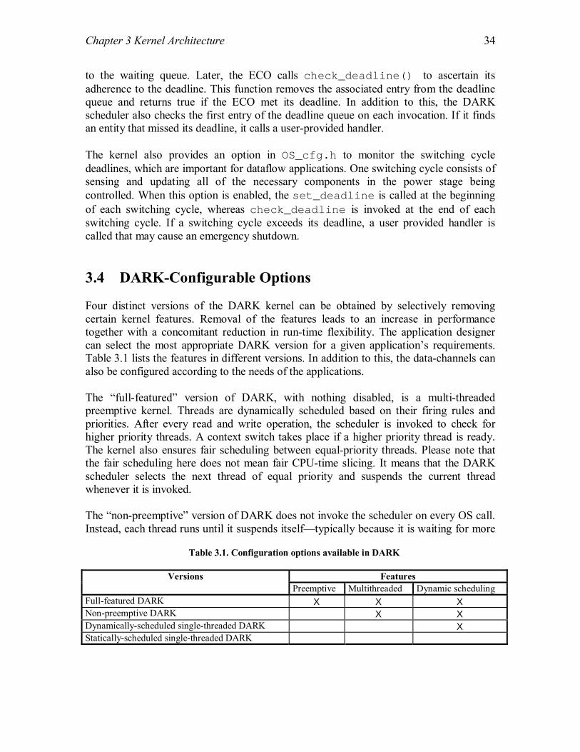
Chapter 3 Kernel Architecture
34
to the waiting queue. Later, the ECO calls check_deadline() to ascertain its adherence to the deadline. This function removes the associated entry from the deadline queue and returns true if the ECO met its deadline. In addition to this, the DARK scheduler also checks the first entry of the deadline queue on each invocation. If it finds an entity that missed its deadline, it calls a user-provided handler. The kernel also provides an option in OS_cfg.h to monitor the switching cycle deadlines, which are important for dataflow applications. One switching cycle consists of sensing and updating all of the necessary components in the power stage being controlled. When this option is enabled, the set_deadline is called at the beginning of each switching cycle, whereas check_deadline is invoked at the end of each switching cycle. If a switching cycle exceeds its deadline, a user provided handler is called that may cause an emergency shutdown. 3.4 DARK-Configurable Options Four distinct versions of the DARK kernel can be obtained by selectively removing certain kernel features. Removal of the features leads to an increase in performance together with a concomitant reduction in run-time flexibility. The application designer can select the most appropriate DARK version for a given application�s requirements. Table 3.1 lists the features in different versions. In addition to this, the data-channels can also be configured according to the needs of the applications. The �full-featured� version of DARK, with nothing disabled, is a multi-threaded preemptive kernel. Threads are dynamically scheduled based on their firing rules and priorities. After every read and write operation, the scheduler is invoked to check for higher priority threads. A context switch takes place if a higher priority thread is ready. The kernel also ensures fair scheduling between equal-priority threads. Please note that the fair scheduling here does not mean fair CPU-time slicing. It means that the DARK scheduler selects the next thread of equal priority and suspends the current thread whenever it is invoked. The �non-preemptive� version of DARK does not invoke the scheduler on every OS call. Instead, each thread runs until it suspends itself�typically because it is waiting for more
Table 3.1. Configuration options available in DARK
Features Versions Preemptive Multithreaded Dynamic scheduling
Full-featured DARK Χ Χ Χ Non-preemptive DARK Χ Χ Dynamically-scheduled single-threaded DARK Χ Statically-scheduled single-threaded DARK

Chapter 3 Kernel Architecture
35
incoming data. Thus, the overhead of calling the scheduler after every read and write operation is avoided by sacrificing immediate response to higher-priority threads. The remaining two versions of DARK are single threaded. They avoid the time spent in context switching, thereby giving a performance boost to the application. Such an approach may be unsuitable for an application with dynamic behavior, but may be ideal for monotonic applications that execute sequentially. The dynamically scheduled, single-threaded version of DARK continues to use firing rules and priorities to select which process is ready for execution. The statically scheduled, single-threaded version of DARK is fastest; it uses a precomputed firing order for threads, eliminating all use of priorities and firing rules. DARK also provides a configurable option for data-channels. The data-channels in a dataflow application can be synchronous or asynchronous. Synchronous channels never contain more than one data item throughout the application execution. In other words, whenever a data item is written, the sink ECO consumes it before any subsequent write into the channel. Asynchronous data channels can contain multiple data items. Many dataflow applications use synchronous channels. The kernel provides a mailbox option, which can be used with any of the four DARK versions listed above with no change to the application code. The mailboxes avoid the costly queue maintenance operations and thus, provide a better performance. In addition to these options, DARK also provides options for adding real-time features as discussed in the previous section. The user can select a fixed priority real-time scheduling algorithm such as RMA using a handler in the DFG.h file. The option of monitoring deadlines for each switching cycle can also be selected by the application designer. The next chapter provides an overview of the DARK API. It explains all the functions available to the application designers, and may be used as a small kernel manual while designing dataflow applications.

36
Chapter 4 Kernel API This chapter explains the Application Programming Interface provided by DARK. The configuration API file (OS_Cfg.h) enables the application designer to selectively remove the kernel features. It is discussed in Section 5.2 of the next chapter. DARK provides operations for reading from and writing to data channels that are implemented as macros inside the kernel to reduce the overhead. DARK also offers a precise API for thread and time management. The threads can suspend themselves while waiting for data to arrive on the incoming data channels. They can also delay themselves for a specific time. In addition to this, the kernel also provides an API that can be used for debugging the applications. In the Section 4.1, we describe the functions available for communication between ECOs. The Section 4.2 discusses the interface services for managing the threads or ECOs. DARK also provides services that deal with time or delays. Section 4.3 contains an overview of those services. The interface provided by DARK for the management of data channels is described in Section 4.4. Some special functions that can be used for debugging are explained in Section 4.5. 4.1 Inter-ECO Communication In dataflow architecture, the ECOs or threads can communicate only through data channels. DARK provides typed data channels along with support for complex data types like single dimensional byte arrays and multidimensional arrays of integers, floats and double data types. The communication API consists of functions for writing to and reading from data channels. All of these functions are implemented as macros that in turn reduce the function call overhead and increases the performance. Section 4.1.1 contains the API for reading and writing simple data types, while the API for reading and writing byte arrays and complex multidimensional arrays is given in Sections 4.1.2 and 4.1.3, respectively. 4.1.1 Write/Read Simple Data Types In this section, the API for reading and writing simple data types is discussed. DARK supports Boolean, Character, Integer, Float, Double and Pointer data types, in addition to complex data types discussed in the Sections 4.1.2 and 4.1.3.
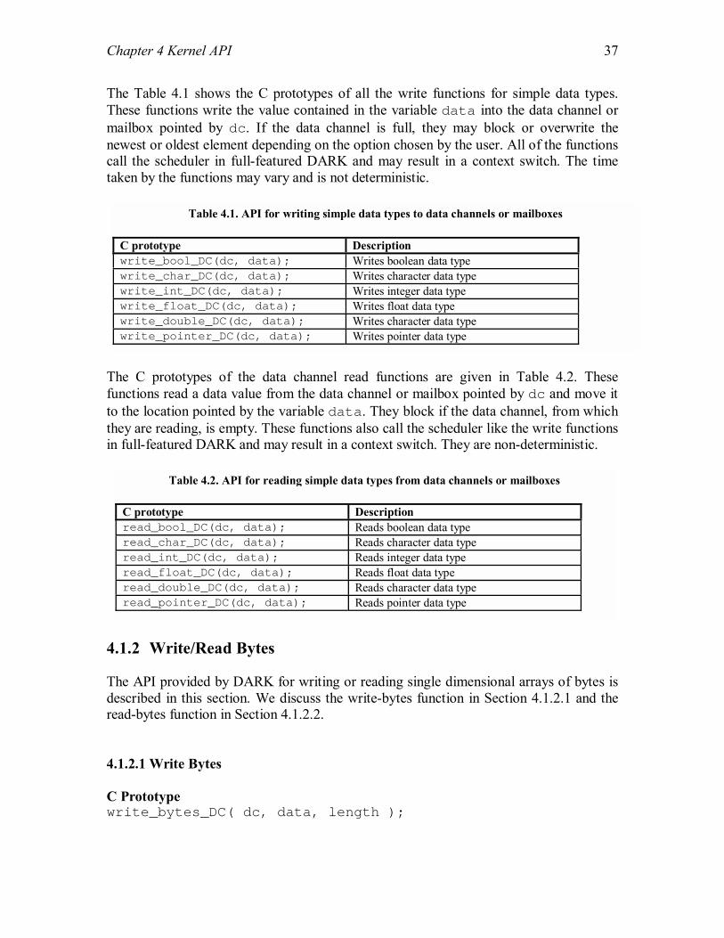
Chapter 4 Kernel API
37
The Table 4.1 shows the C prototypes of all the write functions for simple data types. These functions write the value contained in the variable data into the data channel or mailbox pointed by dc. If the data channel is full, they may block or overwrite the newest or oldest element depending on the option chosen by the user. All of the functions call the scheduler in full-featured DARK and may result in a context switch. The time taken by the functions may vary and is not deterministic.
The C prototypes of the data channel read functions are given in Table 4.2. These functions read a data value from the data channel or mailbox pointed by dc and move it to the location pointed by the variable data. They block if the data channel, from which they are reading, is empty. These functions also call the scheduler like the write functions in full-featured DARK and may result in a context switch. They are non-deterministic.
4.1.2 Write/Read Bytes The API provided by DARK for writing or reading single dimensional arrays of bytes is described in this section. We discuss the write-bytes function in Section 4.1.2.1 and the read-bytes function in Section 4.1.2.2. 4.1.2.1 Write Bytes C Prototype write_bytes_DC( dc, data, length );
Table 4.1. API for writing simple data types to data channels or mailboxes C prototype Description write_bool_DC(dc, data); Writes boolean data type write_char_DC(dc, data); Writes character data type write_int_DC(dc, data); Writes integer data type write_float_DC(dc, data); Writes float data type write_double_DC(dc, data); Writes character data type write_pointer_DC(dc, data); Writes pointer data type
Table 4.2. API for reading simple data types from data channels or mailboxes C prototype Description read_bool_DC(dc, data); Reads boolean data type read_char_DC(dc, data); Reads character data type read_int_DC(dc, data); Reads integer data type read_float_DC(dc, data); Reads float data type read_double_DC(dc, data); Reads character data type read_pointer_DC(dc, data); Reads pointer data type

Chapter 4 Kernel API
38
Description This function writes a block of bytes pointed by the variable data into the data channel or mailbox pointed by dc. The variable length contains the length of the block. If the data channel is full, it may block or overwrite the newest or oldest elements depending on the option chosen by the user. Scheduling This function calls the scheduler in full-featured DARK and may result in a context switch. Determinism Not deterministic 4.1.2.2 Read Bytes C Prototype read_bytes_DC( dc, data, length ); Description This function reads a block of bytes from the data channel pointed by dc and moves it to the location pointed by the variable data. The length of the block to be read is obtained from the variable length. It blocks if the data channel is empty. Scheduling This function calls the scheduler in full-featured DARK and may result in a context switch. Determinism Not deterministic 4.1.3 Write/Read Multidimensional Arrays DARK provides functions for writing multidimensional arrays of integers, floats and doubles as shown in Table 4.3. These functions write an array pointed by the variable data into the data channel or mailbox pointed by dc. The array is stored in row-major order inside the block. The variable array_dim is null terminated list of array dimensions and is used for type checking. If the data channel is full, these functions may block or overwrite the newest or oldest element depending on the option chosen by the user. All of these functions are non-deterministic and, call the scheduler in full-featured DARK and may result in a context switch.
Table 4.3. API for writing multidimensional arrays to data channels or mailboxes C prototype Description write_int_array_DC( dc, data, array_dim ); Writes integer array write_float_array_DC( dc, data, array_dim ); Writes float array write_double_array_DC( dc, data, array_dim ); Writes double array

Chapter 4 Kernel API
39
The functions shown in Table 4.4 read an array from the data channel or mailbox pointed by dc, and move it to the location pointed by the variable data. The array dimensions are obtained from the variable array_dim and are used for type checking. They block if the data channel is empty. These functions also call the scheduler in full-featured DARK and may result in a context switch. They are non-deterministic by nature.
4.2 Thread Management DARK maps each ECO into a separate thread. The threads have dynamic priority that can be changed by user at any time. In addition, the threads can also suspend themselves and wait for data in the incoming data channels. The API for these operations is discussed in this section along with some functions to ascertain deadline adherence. 4.2.1 Wait to Fire C Prototype bool wait_to_fire( void ); Description This function is called by an ECO to fire itself again. It checks for data in the incoming data channels and returns true instantaneously if there is data available in the incoming data channels for firing the ECO. However, if there is no data, it suspends the ECO (wait_for_fire state) and returns control to the scheduler. Scheduling This function may call the scheduler in full-featured DARK if the current ECO is not ready to fire. Determinism Not deterministic 4.2.2 Change Priority C Prototype void set_priority( Process_Data *p, Priority new_priority );
Table 4.4. API for reading multidimensional arrays from data channels or mailboxes C prototype Description read_int_array_DC( dc, data, array_dim ); Reads integer array read_float_array_DC( dc, data, array_dim ); Reads float array read_double_array_DC( dc, data, array_dim ); Reads double array
Chapter 4 Kernel API
40
Description This function is called by an ECO to change its priority. The control returns to the calling ECO after the priority is changed. An ECO can also change the priority of another ECO using this function. The parameter p points to the thread control block of the ECO whose priority is to be changed whereas the parameter new_priority contains the new priority to be assigned. Scheduling This function does not invoke the scheduler. Determinism Constant time 4.2.3 Set Deadline C Prototype void set_deadline( int time ); Description The ECOs can use this function to set execution deadlines. When an ECO call this function, it tells the kernel the time in which it should complete its execution. This function is used in conjunction with the next API function ( check_deadline() ), which is used by the ECO to check whether it has adhered to the deadline that it had set. Scheduling This function does not invoke the scheduler. Determinism Not deterministic 4.2.4 Check Deadline C Prototype bool check_deadline( void ); Description The ECOs can use this function to check whether they have satisfied their execution deadlines. An ECO needs to set a deadline before using this function using the previous API call discussed. This function returns true if the ECO has satisfied the deadline. If the ECO missed the deadline, this function returns false. Scheduling This function does not invoke the scheduler. Determinism Not deterministic

Chapter 4 Kernel API
41
4.3 Time Management This Section discusses the services that deal with time issues. The ECOs can delay themselves by using either of the services described below-the first one is used for non-absolute delays while the second one is used for an absolute delay. 4.3.1 Timed Wait to Fire C Prototype bool timed_wait_to_fire( int delay_time ); Description This function is similar to the wait_to_fire but has an added feature. The user can also specify the time for which the ECO may wait for getting fired using the parameter delay_time. When this function is called, it immediately returns true if there is data in the incoming data channels that can fire the ECO. If there is not sufficient data available, the function waits for the specified duration. If the ECO gets data while waiting, it gets fired. Scheduling This function invokes the scheduler in full-featured DARK if the current ECO is not ready to fire. Determinism Not deterministic 4.3.2 Delay C Prototype bool delay( int delay_time ); Description This function delays the calling ECO for the time specified in the parameter delay_time. It is similar to the sleep() function provided in most of the commercial RTOSes. Scheduling This function invokes the scheduler in full-featured DARK. Determinism Constant time 4.4 Data Channel Management As data channels are an important part of the dataflow architecture, DARK also provides services for data channel maintenance. The first four functions in this Section return the status of the data channels, while the last service flushes the data channel. All of these functions are implemented as macros to reduce the function-call overhead.

Chapter 4 Kernel API
42
4.4.1 Size of Data Channel C Prototype int size_of_DC( dc ); Description This function returns the size of the data channel. The size is the number of elements that can be stored in the data channel. In case of data channels that store byte streams, this function returns the number of bytes that can be stored. The parameter dc is a pointer to the Queue Control Block of the data channel. Scheduling This function does not invoke the scheduler. Determinism Constant time 4.4.2 Entries in Data Channel C Prototype int entries_in_DC( dc ); Description This function returns the current number of elements present in the data channel. The parameter dc is a pointer to the Queue Control Block of the data channel. Scheduling This function does not invoke the scheduler. Determinism Constant time 4.4.3 Bytes in Data Channel C Prototype int bytes_in_DC( dc ); Description This function returns the number of bytes taken by the elements present in the data channel. The parameter dc is a pointer to the Queue Control Block of the data channel. Scheduling This function does not invoke the scheduler. Determinism Constant time

Chapter 4 Kernel API
43
4.4.4 Available Capacity of Data Channel C Prototype int available_capacity_of_DC( dc ); Description This function returns the available capacity of the data channel in terms of number of additional elements that can be stored in it. The parameter dc is a pointer to the Queue Control Block of the data channel. Scheduling This function does not invoke the scheduler. Determinism Constant time 4.4.5 Empty Data Channel C Prototype int flush_DC( dc ); Description This function makes the data channel empty. The parameter dc is a pointer to the Queue Control Block of the data channel. Scheduling This function does not invoke the scheduler. Determinism Constant time 4.5 Debugging DARK also provides a simple API for debugging the programs. Logs can be written to files or terminals during the execution of programs. After debugging, the option can be turned off. The options are set using a kernel header file: log.h. All of these functions are implemented as macros. 4.5.1 Log Message C Prototype void log( msg ); Description This function prints the string (msg) on the terminal or file, depending on the options given in log.h.

Chapter 4 Kernel API
44
Scheduling This function does not invoke the scheduler. Determinism Not deterministic 4.5.2 Log Message with One Argument C Prototype void log_1( msg, arg1 ); Description This function prints the string (msg) with an argument (arg1) on the terminal or file, depending on the options given in log.h. The argument is given in a way similar to arguments in printf. Scheduling This function does not invoke the scheduler. Determinism Not deterministic 4.5.3 Log Message with Two Arguments C Prototype void log_2( msg, arg1, arg2 ); Description This function prints the string (msg) with two arguments (arg1 and arg2) on the terminal or file, depending on the options given in log.h. The arguments are given in a way similar to arguments in printf. Scheduling This function does not invoke the scheduler. Determinism Not deterministic 4.5.4 Log Message with Three Arguments C Prototype void log_3( msg, arg1, arg2, arg3 ); Description This function prints the string (msg) with three arguments (arg1, arg2 and arg3) on the terminal or file, depending on the options given in log.h. The arguments are given in a way similar to arguments in printf. Scheduling This function does not invoke the scheduler. Determinism Not deterministic

Chapter 4 Kernel API
45
4.5.5 Log Message with Four Arguments C Prototype void log_4( msg, arg1, arg2, arg3, arg4 ); Description This function prints the string (msg) with four arguments (arg1, arg2, arg3 and arg4) on the terminal or file, depending on the options given in log.h. The arguments are given in a way similar to arguments in printf. Scheduling This function does not invoke the scheduler. Determinism Not deterministic

46
Chapter 5 Kernel Implementation Dataflow Architecture Real-time Kernel (DARK) is implemented in C, with a few key elements in assembly. Because it is intended for embedded power electronics control, it currently runs on Analog Devices SHARC 21xxx 32-bit digital signal processors. This Chapter describes the implementation of DARK. We have provided an in-depth discussion of all the major components of the kernel. The implementation of important API services is also illustrated. Section 5.1 provides an overview of kernel initialization process during system startup. The implementation of context switching along with high speed context switching is discussed next in Section 5.2. Section 5.3 provides an insight into the implementation of DARK scheduler, which also acts as the idle thread. The data channel operations for reading, writing and retrieving status are described next in Section 5.4. The implementation of API services for thread and time management is given in Section 5.5 and Section 5.6 respectively. Section 5.7 discusses the implementation of minimal footprint interrupt handling in DARK. At the end, the implementation of real-time support is provided. 5.1 Kernel Initialization The kernel initializes itself before the dataflow applications start executing. The initialization is done using an application descriptor file provided by the user. This file contains the Dataflow Graph (DFG) that describes the application ECOs and connections between them. In Section 5.1.1, we describe the overall structure of a dataflow application and the header files for OS configuration. The DFG descriptor file and system startup process is discussed next in Section 5.1.2. 5.1.1 Configuration As discussed in the previous chapters, the Elementary Control Objects (ECOs) allow power electronics control applications to be developed rapidly by simply wiring together existing dataflow components. So, a library of reusable dataflow components is maintained for the power electronics control domain. Figure 5.1 shows the directory structure that is adopted for dataflow applications in the power electronics control domain.
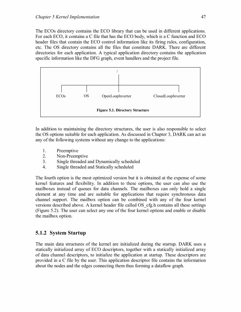
Chapter 5 Kernel Implementation
47
The ECOs directory contains the ECO library that can be used in different applications. For each ECO, it contains a C file that has the ECO body, which is a C function and ECO header files that contain the ECO control information like its firing rules, configuration, etc. The OS directory contains all the files that constitute DARK. There are different directories for each application. A typical application directory contains the application specific information like the DFG graph, event handlers and the project file. In addition to maintaining the directory structures, the user is also responsible to select the OS options suitable for each application. As discussed in Chapter 3, DARK can act as any of the following systems without any change to the applications:
1. Preemptive 2. Non-Preemptive 3. Single threaded and Dynamically scheduled 4. Single threaded and Statically scheduled
The fourth option is the most optimized version but it is obtained at the expense of some kernel features and flexibility. In addition to these options, the user can also use the mailboxes instead of queues for data channels. The mailboxes can only hold a single element at any time and are suitable for applications that require synchronous data channel support. The mailbox option can be combined with any of the four kernel versions described above. A kernel header file called OS_cfg.h contains all these settings (Figure 5.2). The user can select any one of the four kernel options and enable or disable the mailbox option. 5.1.2 System Startup The main data structures of the kernel are initialized during the startup. DARK uses a statically initialized array of ECO descriptors, together with a statically initialized array of data channel descriptors, to initialize the application at startup. These descriptors are provided in a C file by the user. This application descriptor file contains the information about the nodes and the edges connecting them thus forming a dataflow graph.
/
ECOs OS OpenLoopInverter ClosedLoopInverter
Figure 5.1. Directory Structure

Chapter 5 Kernel Implementation
48
/*--------------- OS Options available to the user ----------------*/ /* Preemptive and multithreaded DARK with firing rules & dynamicscheduling */ #define PREEMPTIVE_MTHREADED 1 /* Non-Preemptive and multithreaded DARK with firing rules & * dynamic scheduling */ #define NONPREEMPTIVE_MTHREADED 0 /* Dynamically scheduled, single threaded DARK with firing rules */ #define SINGLETHREAD_DYNSCHD 0 /* Statically scheduled, single threaded DARK with no firing rules */ #define SINGLETHREAD_STATSCHD 0 /*-----------------------------------------------------------------*/ #define MONITOR_SWCYCLE_DEADLINE 0 /*--------------------- Data Channel options ----------------------*/ #define USE_MAILBOX 0
Figure 5.2. OS Options in OS_cfg.h
Figure 5.3 shows the structure of node and edge descriptors that is given in a kernel file called DFG.h. The application descriptor file uses these structures to define the dataflow graph for a particular application. The eco field of the DFG_Node structure contains information about the ECO such as its C function, stack size needed for it, etc. The configuration field contains specific configuration information about the ECO that may vary from application to application. The firing_rules field points to an array of various firing rules that the ECO can use whereas the firing_rule_name contains the name of the firing rule that is being used in the current application. The initial_priority gives the initial priority of the thread when the application starts. The default_mask contains the mask to be used in case of static-scheduled DARK without firing rules. The fields: period and execution_time are used for calculating priorities if the application designer uses the rate monotonic scheduling algorithm. The assigned_processor field is used identify the processor on which the current node or thread is allocated. This field is used in Distributed-DARK, which is presently under development. In the DFG_Edge structure in Figure 5.3, the type field specifies the type of elements that the data channel or mailbox will contain. The next four fields describe the connection between two nodes. The source and source_out_port fields contain the source node number and the output port number of the source node to which this edge is connected. Similarly, the sink and sink_in_port fields give the sink node number and the input port number of the sink node to which the edge is connected. The overflow_style contains one of the three values - overwrite_oldest, overwrite_newest and block. They indicate the action that should be taken in case of an overflow. The size gives the size of data channel in terms of elements while

Chapter 5 Kernel Implementation
49
typedef struct { ECO eco; ECO_Configuration configuration; Firing_Rule *firing_rules; int firing_rule_name; Priority initial_priority; Firing_Mask default_mask; int period; int execution_time; unsigned int assigned_processor; } DFG_Node; typedef struct { Type_Tag type; Node_Number source; Port_Number source_out_port; Node_Number sink; Port_Number sink_in_port; Overflow_Style overflow_style; unsigned int size; Array_Descriptor array_dimensions; bool interrupt_driven; void* ISR_signal_value; unsigned int update_frequency; } DFG_Edge;
Figure 5.3. Dataflow Graph Representation
array_dimensions contains the dimensions if the data channel is of array type. The field interrupt_driven is true for interrupt driven data channels where event handlers write to the data channels directly. ISR_signal_value points to data that may be used in case of interrupt driven data channels. Again, the field update_frequency is used in Distributed-DARK, which is under development. The user is responsible for defining these structures in the application descriptor file, thus specifying the dataflow graph that is used for the application. The kernel uses this file for initializing the structures such as Thread Control Block (TCB) and Queue Control Block (QCB) during the system startup. In addition to this, the stacks for every thread are also initialized. The space for all other kernel data structures such as the ready queue, event queue, waiting queue, etc. is also allocated during startup. Currently DARK uses the C malloc() function for allocating the memory. As this function is unpredictable and costly, it is only used during the kernel startup. Allocation or de-allocation of memory is never done, once the application starts executing. More insight into writing application descriptor files for dataflow applications is provided in the next Chapter. Some applications used in the power electronics control domain are also discussed.
Chapter 5 Kernel Implementation
50
5.2 Context Switching Switching the CPU to another process requires saving the state of the old process and loading the saved state for the new process. This task is known as a context switch. Context-switch time is pure overhead, because the system does no useful work while switching. Context-switch times are highly dependent on hardware support [5]. For instance some processors (such as Analog Devices SHARC and DECSYSTEM-20) provide multiple sets of registers. In these processors, a context switch simply includes changing the pointer to the current register set. Of course, if there are more active processes than there are register sets, the system resorts to copying register data to and from memory, as before. As mentioned in Chapter 3, high-performance in terms of execution speed is one of the main requirements of power electronics controllers. The control software currently uses Analog Devices SHARC 21xxx 32-bit digital signal processors, which have two register sets. We have used this hardware feature for reducing the context-switch time overhead in DARK. Like most RTOSes, DARK saves and restores only selected registers during a context switch. The registers that are not used by the C run-time environment are not saved. Most context switches in a dataflow application occur between the scheduler and executing threads. Minimizing the cost of such switches will increase performance. There are two register sets in SHARC processors-primary set and alternate set. DARK uses the primary set for running the kernel whereas alternate set is used for the ECOs. Thus, the context switch between the kernel and ECOs requires flip of a single bit and saving and restoring some common system registers. For the context switch, we have written many procedures in SHARC assembly that are used for different purposes. They are described below: int setjmp_all( &env ): This procedure saves all the C-runtime registers including system registers in the structure env. It also saves the instruction pointer at the end. This function returns 0, if it is called by its name and is not entered through other means (such as longjmp_all). void longjmp_all( &env, return_value ): longjmp_all is used in conjunction with setjmp_all. setjmp_all saves all the registers whereas longjmp_all restores all the values from env. At the end it restores the instruction pointer, which causes a jump inside setjmp_all. The return_value contains a value that should be returned by the setjmp_all procedure if it is entered through a longjmp_all. Please note that the procedure longjmp_all never returns. Figure 5.4 shows an example illustrating the usage of these functions. We assume that the context of Thread 2 is stored in the structure thread_2_env and the Thread 1 is

Chapter 5 Kernel Implementation
51
currently executing. The if statement in the Thread 1 causes a call to setjmp_all which in turn saves the context of Thread 1 and returns 0. The longjmp_all inside the if body causes a switch to Thread 2. After completing its computation, Thread 2 can switch back to thread 1 by calling longjmp_all. After restoring the instruction pointer, the execution starts from inside the setjmp_all procedure in Thread 1. This time setjmp_all returns 1 instead of 0 and thus, the Thread 1 continues running. In addition to these procedures, we have also developed procedures for a shallow context switch. A shallow context-switch occurs between two register sets and thus does not save or restore all the registers. These procedures are used to switch between two threads that are using different register sets. They flip a bit in the MODE1 register of SHARC processors, which is used for flipping the register sets. There are two procedures for context switching between two register sets. Their usage is similar to the procedures described above. int shallow_setjmp_all( &env ): This procedure stores the system registers that are common to both primary and alternate sets. It also saves the instruction pointer at the end. This function returns 0, if it is called by its name and is not entered through other means (such as shallow_longjmp_all). void shallow_longjmp_all( &env, return_value ): This procedure is similar to longjmp_all. It restores the common system registers and the instruction pointer and causes a context switch to a thread running in the other register set. At the end it restores the instruction pointer, which causes a jump inside shallow_setjmp_all. The return_value contains a value that should be returned by the shallow_setjmp_all procedure if it is entered through a shallow_longjmp_all. Please note that the procedure shallow_longjmp_all never returns. The context switches between the kernel and the ECOs use shallow context switching procedures whereas the switches between the ECOs use normal context switching as all the ECOs run on the same register set.
// Thread 1 if ( setjmp_all( &thread_1_env ) == 0 ) { longjmp_all( &thread_2_env, 1 ); } // Thread 1 continues // …… // Thread 2 // Do Computation // …… longjmp_all( &thread_1_env, 1 );
Figure 5.4 Context Switching Example

Chapter 5 Kernel Implementation
52
5.3 Scheduling Dataflow applications have different scheduling requirements than the traditional applications. Unlike scheduling in traditional applications, dataflow scheduling depends both on thread priority and data in the incoming data channels. As explained in the Chapter 3, DARK uses firing rules for thread scheduling. The major scheduling in DARK takes place in the functions that write data to the data channels. This is due to the fact that writing data into the data channel may make the sink thread ready to run. So whenever data is written to a data channel, the firing rule of the thread connected as the sink node is tested. If the sink thread becomes eligible to run, it is added to the ready queue. After the read and write function, the kernel dispatcher is called so that the higher priority thread can be selected to run. In addition to read and write functions, the call to other API functions like wait_to_fire, timed_wait_to_fire and delay also calls the scheduler/dispatcher. So, the DARK scheduler is called as a result of calling the kernel API functions unlike other kernels where the scheduler is called based on clock ticks, etc. This is due to the fact that in dataflow applications, the instances where a higher priority thread can become ready to run are clearly defined. So, the unnecessary overhead of checking for the higher-priority ready threads is avoided. Figure 5.5 shows the scheduling of a sink thread as is done inside the write macro. The variable in_ports_ready indicates the current status of the incoming data channels as discussed in Section 3.3.2.1. The write macro first sets the appropriate bit of in_ports_ready to indicate presence of data in an incoming data channel. After that, the firing rule which is an array holding firing masks and corresponding priorities (Section 3.3.2.1) is used to check, whether the sink ECO is ready to fire. The firing masks are arranged in the order of decreasing priorities inside a firing rule. If a match is found, the sink ECO takes a new priority and wakeup_call variable inside the thread control block is set equal to firing mask for communicating the reason for firing to the sink ECO. Next, the sink ECO�s state is set to ready and it is added to the ready queue. The ready queue in DARK is implemented as a max-heap, which takes only O(log n) time for insertion and deletion. The other suitable data structures like linked lists, arrays, etc. take O(n) time. Similarly, the read macro is responsible for resetting the appropriate bit in the variable in_ports_ready, if the data channel becomes empty after the operation. The kernel dispatcher is a simple while loop that also acts as an idle task when no threads are ready to run. The dispatcher is called after many API functions as described above and is responsible for selecting the highest priority thread for execution. The dispatcher also does other tasks such as checking for events (that come via interrupts), checking the timed waits of the waiting threads and checking the deadline queue for deadline misses. Figure 5.6 shows the pseudo-code for the dispatcher, which is the part of the kernel that executes continuously. The kernel dispatcher uses the primary register set for execution whereas the ECOs execute in the alternate register set.

Chapter 5 Kernel Implementation
53
5.4 Data Channel Operations In Section 3.3.1.2, we discussed the Queue Control Block (QCB) that stores the control information related to a data channel. The space for the data channels is also allocated along with the QCBs. The last field of the QCB structure (buffer) is used as a base to access the individual locations in the data channel. The data channel is implemented as a
Firing_Rule temp_rule = snk_process->firing_rule;\ snk_process->in_ports_ready |=\ ( 1 << DFG_Edge_Set[qptr->index].sink_in_port ); \ while (temp_rule->priority != -1)\ {\
if ( ( snk_process->in_ports_ready & temp_rule->mask )\ == temp_rule->mask\ )\ {\ snk_process->p.current_priority = temp_rule->priority;\ snk_process->p.wakeup_call = temp_rule->mask;\ snk_process->process_state = ready;\ insert_ready_queue( snk_process, &ready_queue_size );\ break;\ }\ temp_rule++;\ }\
Figure 5.5. Segment of Write Macro Responsible for Scheduling
while (true) { if (deadline_queue_size > 0) { check the deadlines; }
if (actions_pending != no_actions) { handle delayed threads; handle interrupt events; } if (ready_queue_size > 0) { if (high/equal priority thread == ready or called for the first time ) { current_thread = thread at front of queue; execute thread; } else if (current thread == ready) { execute thread; } } }
Figure 5.6 Kernel Dispatcher: Pseudo-code
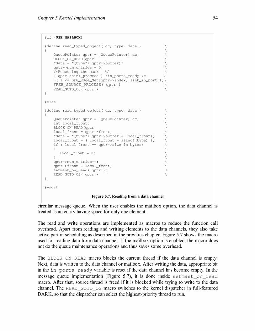
Chapter 5 Kernel Implementation
54
circular message queue. When the user enables the mailbox option, the data channel is treated as an entity having space for only one element. The read and write operations are implemented as macros to reduce the function call overhead. Apart from reading and writing elements to the data channels, they also take active part in scheduling as described in the previous chapter. Figure 5.7 shows the macro used for reading data from data channel. If the mailbox option is enabled, the macro does not do the queue maintenance operations and thus saves some overhead. The BLOCK_ON_READ macro blocks the current thread if the data channel is empty. Next, data is written to the data channel or mailbox. After writing the data, appropriate bit in the in_ports_ready variable is reset if the data channel has become empty. In the message queue implementation (Figure 5.7), it is done inside setmask_on_read macro. After that, source thread is freed if it is blocked while trying to write to the data channel. The READ_GOTO_OS macro switches to the kernel dispatcher in full-featured DARK, so that the dispatcher can select the highest-priority thread to run.
#if (USE_MAILBOX) #define read_typed_object( dc, type, data ) \ { \ QueuePointer qptr = (QueuePointer) dc; \ BLOCK_ON_READ(qptr) \ *data = *(type*)(qptr->buffer); \ qptr->num_entries = 0; \ /*Resetting the mask */ \ ( qptr->sink_process )->in_ports_ready &= \ ~( 1 << DFG_Edge_Set[qptr->index].sink_in_port );\ FREE_SOURCE_PROCESS( qptr ) \ READ_GOTO_OS( qptr ) \ } #else #define read_typed_object( dc, type, data ) \ { \ QueuePointer qptr = (QueuePointer) dc; \ int local_front; \ BLOCK_ON_READ(qptr) \ local_front = qptr->front; \ *data = *(type*)(qptr->buffer + local_front); \ local_front = ( local_front + sizeof(type) ); \ if ( local_front == qptr->size_in_bytes) \ { \ local_front = 0; \ } \ qptr->num_entries--; \ qptr->front = local_front; \ setmask_on_read( qptr ); \ READ_GOTO_OS( qptr ) \ } #endif
Figure 5.7. Reading from a data channel

Chapter 5 Kernel Implementation
55
In addition to writing data, the write macro is also responsible for checking the firing rules of the sink thread and scheduling it, if it is ready as discussed in the previous Section. The implementation of BLOCK_ON_WRITE macro is shown in Figure 5.8. As shown, the macro takes different actions depending on the option selected by the user for the data channel. In case of mailboxes, the user can select any of the three options, but both overwrite_newest and overwrite_oldest are similar as they overwrite the same element. 5.5 Thread Management Operations In this Section, we will discuss two important operations that are used for thread management. One of them is an API service called wait_to_fire, which is used for firing an ECO again after completing a computation. If the ECO is ready to fire, then this function returns true else it suspends the ECO thread. The other operation described in this Section is swap, which is a kernel function to convert the state of a running thread to a different state. Figure 5.9 shows the wait_to_fire function. An ECO calls this function when it finishes computation on received data and needs new data for the next cycle of
#define BLOCK_ON_WRITE( qptr, type ) \ { \ while ( full( qptr ) ) \ { \ switch ( qptr->overflow_style ) \ { \ case OS_Block: \ qptr->blocked = true; \ swap( blocked ); \ break; \ case OS_Overwrite_Newest: \ qptr->rear -= sizeof(type); \ if ( qptr->rear < 0 ) \ { \ qptr->rear += \ qptr->size_in_bytes; \ } \ break; \ case OS_Overwrite_Oldest: \ qptr->front = \ ( qptr->front + sizeof(type) ); \ if ( qptr->front == qptr->size_in_bytes ) \ { \ qptr->front = 0; \ } \ break; \ } \ } \ }
Figure 5.8. Handling channel overflow in write macro

Chapter 5 Kernel Implementation
56
computations. The wait_to_fire function first checks the in_ports_ready variable that gives the current status of incoming data channels. If there is data in the incoming data channels and one of the firing masks is satisfied, the function returns true. Otherwise, the kernel suspends the thread and sends it to the wait_for_fire state by calling the swap function. The swap function is used to change a thread�s state and is shown in Figure 5.10. It takes the new state as an argument and sets the TCB field process_state to this value. Then, it calls the kernel dispatcher after saving the current thread�s state. If the next state of the thread is dead, there is no need to save the state as shown in the function. 5.6 Time Management Operations The implementation of two API services used for delaying a thread is discussed in this Section. The first service is timed_wait_to_fire, which is similar to wait_to_fire described in the previous Section. Like wait_to_fire, it is used to fire an ECO again. If the ECO is not ready to fire, the associated thread is sent to the timed_wait_for_fire state and control is given to the kernel dispatcher. It is different from wait_to_fire in that it wakes up the thread after definite period of
bool wait_to_fire( void ) {
Process *this_process = current_process; Firing_Rule temp_rule = this_process->firing_rule; while ( temp_rule->mask != 0 ) { if ( this_process->in_ports_ready == temp_rule->mask ) { return true; } temp_rule++; } swap( wait_for_fire ); return true; }
Figure 5.9. Wait to Fire
void swap( Process_State next_state ) { current_process->process_state = next_state; if ( next_state == dead ) { shallow_longjmp( &OS_env, 1 ); }
if ( setjmp_all( &(current_process->process_env) ) == 0) { shallow_longjmp( &OS_env, 1 ); } return; }
Figure 5.10. Swap: Changing process state

Chapter 5 Kernel Implementation
57
time even if the ECO is not fired. So, if timed_wait_for_fire is used, a thread can wake up by either firing or time expiration. Figure 5.11 shows the implementation of the function. First of all the firing rule is checked and the function returns true immediately if the ECO is already ready to fire. Otherwise the ECO thread is suspended for a definite time as specified by the parameter delay_time. The second service for delaying threads is delay that delays a thread for a certain time as indicated by the function parameter (Figure 5.12). When this function is called, the kernel puts the thread into timed_wait state until the specified delay expires. As can be noticed in Figures 5.11 and 5.12, the mechanism used for delaying the threads is same in both functions. It is described next. In other kernels, the waiting threads are checked at each clock tick, and they are added to the ready queue when the waiting period has expired. This technique can introduce unnecessary cost if there are more than a tiny number of waiting threads. We have used a different technique for timed waits in DARK. DARK maintains the current system time in a global variable named current_time, which is update at every clock tick. When the delay() or timed_wait_for_fire() function is called, the delay time is converted into an absolute time by adding the current system time to it and then stored in the TCB. The thread is then added to a (circular) waiting queue arranged in ascending order by absolute time. When a thread is added to the waiting queue, a kernel variable
bool delay( int delay_time ) { current_process->wakeup_time = delay_time + current_time; actions_pending = future_actions; insert_waiting_queue( current_process ); swap( timed_wait ); return true; }
Figure 5.12. Delay
bool timed_wait_to_fire( int delay_time ) { Process *this_process = current_process; Firing_Rule temp_rule = this_process->firing_rule; while ( temp_rule->mask != 0 ) {
if ( this_process->in_ports_ready == temp_rule->mask ) { return true; } temp_rule++; } this_process->wakeup_time = delay_time + current_time; actions_pending = future_actions; insert_waiting_queue( this_process ); swap( timed_wait_for_fire ); return true; }
Figure 5.11. Timed wait to Fire

Chapter 5 Kernel Implementation
58
actions_pending is set to future_actions to indicate that the scheduler should check the waiting queue. Each time the DARK dispatcher is called, it checks the actions_pending (Figure 5.6). If the actions_pending is not set to no_actions, it compares the system time with the thread wakeup time of the first thread in the waiting queue. The thread is added to the ready queue if the waiting time has expired. The scheduler need only check the first thread in the waiting queue unless that thread�s wait is over. 5.7 Interrupt Handling The interrupt handling in kernels is usually closely tied to the hardware. Interrupts can be caused by a variety of conditions, both internal and external to the processor. An interrupt forces a subroutine call to a predefined address, the interrupt vector. The Analog Devices SHARC Processor-2106x assigns a unique vector to each type of interrupt [33]. Externally, the ADSP-2106x supports three prioritized interrupts, each of which can be either level or edge-triggered. Among the internally generated interrupts are arithmetic exceptions, timer, stack overflows, and circular data buffer overflows. A power electronics digital signal processor uses all the three external interrupts available. The external interrupt pin IRQ2 has the highest priority and is used for non-Maskable Interrupts (NMI). The NMI interrupt is used for emergency condition notification and requires a time critical response. In most cases, it results in a call to the application�s emergency shutdown procedure, bypassing all other DARK and application code. IRQ1 is used by the DSP for clock synchronization with adjacent DSPs and will be used for Distributed controllers that are under construction. All the external interrupts received by the kernel are tied to the pin IRQ0. DARK uses a minimal footprint interrupt handling technique for handling the external interrupts. Rather than placing actions directly in the interrupt handler itself, DARK uses a small-footprint handler that simply logs incoming events into an �event queue�, which is a circular queue, managed by the DARK kernel thread. The interrupt handler runs in the currently active register set and only needs to save and restore a couple of registers. It logs a 32-bit code representing the interrupt that was received into a circular buffer of incoming events and sets the actions_pending variable to current_actions. After that, the control returns to the thread that was interrupted. This queue of events is translated into messages sent on data channels to the application the next time the dispatcher thread checks for actions_pending. Figure 5.13 shows the interrupt service routine used for IRQ0 that adds a 32-bit event code to the event queue. As shown in the Figure, instead of saving and restoring all the registers while handling the interrupts as done by the other kernels, DARK only saves and restores six registers. This approach reduces the time spent in handling the interrupts and increases the system performance.

Chapter 5 Kernel Implementation
59
Apart from the external interrupts, DARK also uses an internal interrupt for the time management. The ADSP-2106x includes a programmable interval timer, which can generate periodic interrupts. The timer is programmed by writing values to its two control registers and the timer operation is controlled through a bit in the MODE2 system register. DARK uses an interrupt vector named TMZLI for servicing this interrupt, which has a lower priority than any of the interrupts discussed above. The interrupt service routine for handling this interrupt is also minimal footprint and causes minimum
___lib_IRQ0I: BIT CLR MODE1 0x1000; /* Disable interrupts */
JUMP (pc,3) (DB); /* Jmp to finish setting up*/ !DM(I7,M7)=I15; /* Save I15 (scratch reg) */ BIT SET MODE2 0x80000; /* Freeze cache */ /* Saving the necessary registers */ dm(r5_store)=R5; dm(r6_store)=R6; dm(r7_store)=R7; dm(astat_store)=ASTAT; dm(i5_store)=I5; dm(m4_store)=M4; /* ISR Body */ R5 = dm(_event_code); /* Written by FPGA */ I5 = _event_queue; MODIFY(I5,1); /* Point to rear */ R6 = dm(0,I5); /* R6 contains queue rear */ MODIFY(I5,1); /* Pointing to event queue */ R6 = R6 + 1; /* Advancing rear */ R7 = MAX_LENGTH_EVENT_Q; /* Circular queue */ COMP(R6,R7); /* maintenance */ IF NE JUMP(PC,2); R6 = 0; /* Rotating rear */ M4 = R6; dm(M4,I5) = R5; /* Writing event code */ I5 = _event_queue; MODIFY(I5,1); /* Point to rear */ dm(0,I5)=R6; /* Recording rear */ R5=0x2; dm(_actions_pending) = R5; /* Setting actions pending*/ /* Restoring the registers */ I5=dm(i5_store); M4=dm(m4_store); ASTAT=dm(astat_store); R5=dm(r5_store); R6=dm(r6_store); R7=dm(r7_store); /* Returning from the ISR */ RTI(DB); /* Return from interrupt */ BIT SET MODE1 0x1000; /* Re-enable Int */ BIT CLR MODE2 0x00080000; /* Re-enable cache */
Figure 5.13. ISR for external interrupts

Chapter 5 Kernel Implementation
60
overhead to the system. The routine just updates a global variable current_time each time it is invoked. 5.8 Real-time Support As explained in Section 3.3.2.7, DARK provides options to application designers for using real-time features along with an API to monitor deadlines. The application designer can use any fixed priority real-time scheduling algorithm for assigning the thread priorities. The DFG.h header file defines a function handle that can be used to add any static scheduler definition. The function handle is assigned to implementation of a particular algorithm inside the application descriptor file. The default DARK scheduler is used if the function handle is assigned to null. DARK provides a static scheduler, which uses Rate Monotonic Priority Assignment (RMA) algorithm by Liu and Layland [7] for assigning priorities to a set of tasks. If the function handle is set to its implementation, then the algorithm uses the period and execution_time fields of DFG_Node for feasibility analysis and quits if the threads are not schedulable. If the thread set is feasible, it calculates and assigns priorities to each thread. Next, we provide a brief overview of the implementation of RMA in DARK. A set of N tasks can be scheduled using rate-monotonic priorities if and only if [25]: N
∑ Ci / Ti ≤ U(N) i = 1
Here Ci is the execution time of a task i, whereas Ti is its period. The ratio Ci/Ti is called the CPU utilization of task i. U(N) is the processor utilization for N tasks, which has been shown to be the following [25]:
U(N) = N ( 21 / N - 1) For larger values of N, this equation converges to 0.693. So we can conclude that a set of tasks are schedulable using RMA, if the sum of their CPU utilization factors is less than or equal to 0.693. DARK�s real-time scheduling algorithm uses these formulae to determine the feasibility of the thread set, before assigning priorities. If the thread set is found to schedulable, then the task with the shortest period gets the highest priority. Please note that DARK provides the flexibility to the application designer to use any other scheduling algorithm through the use of function handle. DARK also provides options to monitor the switching cycle deadlines, which are very important for dataflow applications. One switching cycle consists of sensing and updating all of the necessary components in the power stage being controlled. The application designer can specify the switching cycle deadline inside the application descriptor file. Whenever the option for monitoring switching cycle deadline is enabled in OS_cfg.h

Chapter 5 Kernel Implementation
61
(Figure 5.2), DARK sets the deadline at the start of the switching cycle and checks the adherence to the set deadline at the end of the switching cycle. These actions are taken inside the kernel dispatcher using the API functions: set_deadline and check_deadline. Before the kernel calls these operations, the current_process kernel variable is always set to null to communicate the fact that it is not called by an ECO. In addition to this, these two API functions can also be used inside ECOs by the application designers to monitor individual ECO deadlines. Whenever the function set_deadline( int time ) is called, the time is converted to an absolute time by adding the current system time to it. The ECO pointer, obtained through the current_process kernel variable, is then added to a deadline queue. The deadline queue is a queue of structures containing ECO pointers and absolute times, arranged in ascending order. If the calling entity is kernel, then a null pointer is added with an absolute time. Later, check_deadline () is called to ascertain adherence to the deadline. This function removes the associated entry from the deadline queue and returns true if the entity met its deadline. In addition to this, the DARK scheduler also checks the first entry of the deadline queue on each invocation. If it finds an entity that missed its deadline, it calls a user provided handler. In the next chapter, we will discuss some applications that are using DARK as a platform. We will also describe the structure of a simple dataflow application written for power electronics control domain.

62
Chapter 6 Dataflow Applications Dataflow software consists of a collection of independent components running concurrently that communicate through data channels. In power electronics domain, the components are called Elementary Control Objects (ECOs) [20]. By using a design library of commonly needed ECOs, a new control system can be rapidly configured from an existing collection of components. Each ECO manipulates input data that it receives according to its functionality, generating output that can be connected to other ECOs [22]. There are no explicit calls between ECOs�in fact, no ECO knows anything about the other nodes the system comprises, or the identities of the other nodes with which it communicates. Three distinct types of ECOs exist within the embedded power electronics control domain�computational ECOs, coordination ECOs, and driver ECOs. A computational ECO performs some specific computation needed for an application. A coordination ECO, on the other hand, is designed to support transparent management and control of distributed system hardware resources. Driver ECOs encapsulate hardware dependencies and provide a standard program interface to control hardware. This Chapter discusses dataflow applications that are being used in power electronics control. These applications are also used for performance evaluation experiments in the next Chapter. We start with describing the implementation of a simple ECO in Section 6.1. In Section 6.2, a simple application representing an Open Loop Inverter is presented. Section 6.3 describes the feedback-based Closed Loop Inverter. At the end in Section 6.4, we provide an overview of a dataflow application for Boost Rectifier, which contains two loops-a current loop and a voltage loop. 6.1 ECO Implementation An ECO is an entity that processes data received on the incoming data channels and sends the results to the outgoing data channels. In most of the applications, this process is repeated in every switching period. A switching period can be defined as the time taken by the system to process incoming interrupts and generate the outputs. Most of the ECOs are implemented as loops that process the incoming data and wait for new data after writing the results to the outgoing data channels. Figure 6.1 shows the pseudo-code for the implementation of a typical ECO [22]. When the system starts, every ECO is in wait_for_fire state. Data in the incoming data channels fire the ECO.

Chapter 6 Dataflow Applications
63
The ECO processes the data received and writes the results to the outgoing data channels before calling the wait_to_fire() API function that suspends the ECO again. The information about the handles for incoming and outgoing data channels is obtained through the parameter p, which is a part of the Task Control Block (TCB) for the thread that executes the ECO. The fields, in_port and out_port, in the Process_Data structure store handles that are pointers to the incoming and outgoing data channels, respectively (Figure 6.2). As discussed in Chapter 5, the field wakeup_call is used to communicate the firing mask responsible for firing to the ECO, so that the ECO can take a specific action based on that, as shown in Figure 6.1. In the Pseudo-code for the sample ECO, the ECO can take two actions depending on the firing mask that fired it, using a switch statement. A typical action consists of a simple procedure�reading inputs from the input data channels, performing computation, and writing results to output data channels.
void Sample_ECO_Body( Process_Data* p ) { do { switch( p->wakeup_call ) { case SAMPLE_ECO_FIRING_MASK_1: read_type_DC( p->in_port[X1], &x1 ); … /* -- action 1 -- */ … write_type_DC( p->out_port[Y1], y1 ); break; case SAMPLE_ECO_FIRING_MASK_2: read_type_DC( p->in_port[X2], &x2 ); … /* -- action 2 -- */ … write_type_DC( p->out_port[Y2], y2 ); break; default: break; } } while( wait_to_fire() ); }
Figure 6.1 Pseudo-code for a sample ECO
typedef struct { Data_Channels in_port; Data_Channels out_port; ECO_Configuration config; Firing_Mask wakeup_call; Priority current_priority; } Process_Data;
Figure 6.2 Process data structure

Chapter 6 Dataflow Applications
64
As can be seen in this section, the ECOs are entirely independent entities that communicate with each other only through data channels, which increases the modularity and reusability of the dataflow applications. 6.2 Open Loop Inverter Figure 6.3 shows the dataflow graph for an open loop control algorithm for a PEBB-based 3-phase inverter [22,23]. Every ECO in this dataflow graph gets executed exactly during a switching period. As shown in the Figure, the switching cycle gets started when the Lookup_Sin ECOs get a start signal through the three boolean interrupt-driven data channels. The Lookup_Sin ECOs look up a value from a sinusoidal table, which is a part of the configuration data of the ECO. The sequence of values generated by the three ECOs at each switching cycle satisfies 120° phase shifts between the three phases. When the Modulator ECO receives data on its three incoming data channels, it is fired. The Modulator synthesizes these values and generates data for the three PEBB_Driver ECOs. The PEBB_Driver ECO acts as an interface for the driving circuit of the power stage.
The PEBB-based Open-loop Inverter is the simplest application that we have used for the performance evaluation experiments in the next chapter. In the following Sections, we discuss two relatively complex applications containing feedback loops. 6.3 Closed Loop Inverter The dataflow graph of a closed current loop control algorithm for a PEBB-based 3-phase inverter is shown in Figure 6.4. The dq transformation technique is used to simplify the control [22]. The feedbacks, which are input to the ECO Abc_dqo are generated by external A/D converters. They have an initial value to begin with in the first switching
External Interrupts
Lookup_sin Lookup_sin Lookup_sin
Modulator_open
PEBB_driver PEBB_driver PEBB_driver
Figure 6.3. Open loop control for a 3-phase inverter

Chapter 6 Dataflow Applications
65
cycle. The external interrupts fire the two Lookup_Sin ECOs that output the sine and cosine data by using sine and cosine tables respectively. The Duplicator ECO is designed to send the data received on its input channel to two different ECOs. Please note that a Duplicator becomes necessary because one data channel can only have one source and one sink ECO. In the Abc_dqo ECO, the phase currents in abc coordinates are transformed into dqo coordinates. The Regulator ECO performs PI regulation to get duty cycles in dqo coordinates. The Dqo_albe ECO transforms the duty cycles back into αβγ. The Modulator ECO generates duty cycle for the whole power stage. The PEBB_Drivers ECO is a combination of three PEBB driver ECOs and it translates the floating-point format duty cycle into the proper format for the driving circuits on the PEBB. 6.4 Boost Rectifier The Figure 6.5 shows dataflow graph for a 3-phase boost rectifier close loop control [20]. There are two control loops in this application: current loop and voltage loop. The voltage loop is executed first to generate reference for the current loop. For the 3-phase current loop control, the dq transformation technique is used. The feedback is given through interrupt driven data channels, synchronized by the switching clock. The rising edge of the switching clock causes the execution of the corresponding interrupt handler, in which all the sensed data, phase currents and voltages and dc voltage are updated. Those ADC drivers then translate those sensed data to correct values, respectively. At this point ECO 1-D regulator and Synchronize get ready. The dc voltage is regulated in the ECO 1-D regulator, and the current loop reference dd_ref is generated. The Synchronize ECO tests the phase voltages and generates a Boolean output to indicate whether the phase angles need synchronizing. The two Lookup_table ECOs have two different behaviors depending on different inputs combinations. At normal condition, if the phase voltages do not need synchronizing, the
Feedbacks
Lookup_sin
Lookup_sin
Duplicator
Duplicator
Abc_dqo
Regulator
Modulator
Dqo_albe
PEBB_drivers
Figure 6.4. Closed loop control for a 3-phase inverter
External Interrupts

Chapter 6 Dataflow Applications
66
Lookup_table ECOs increment their table pointers and output the table value; otherwise, the table pointers will be reset. Through ECO Duplicator, the sine and cosine values are copied and directed to two different ECOs. Then, the abc_dqo ECO transforms the phase currents in abc coordinates to dqo coordinates. Then the 2-D regulator performs the current loop regulation with the reference generated from the voltage loop. The regulated currents in dqo coordinates are then transformed back to αβγ coordinates through the ECO dqo-αβγ. Then the ECO �3-D Modulator� synthesizes duty cycle information for each phase. In the PEBB driver ECO, the duty cycle information is translated to the form that can be used to generate switch pulse at the phase leg. The library of ECOs is still under construction and new ECOs are being added to enable the developers to develop new applications faster. More information about the power electronics dataflow applications can be obtained from the website of Power Electronics Building Blocks (PEBB) Research Group at Virginia Tech [39]. In the next chapter, we provide the result of performance evaluation experiments. We have used all the three applications described in this chapter for our experiments. The chapter provides a measure of relative performance gains achieved by selectively removing DARK features using configurable options along with a comparison of DARK�s performance with other three commercial kernels.
2-D Regulator
dd
sinθLook_up Sin_table
Look_up Cos_table
IbADC_IB driver
ADC_B
abc-dqo
IaADC_IA driver
ADC_A
cosθ
dq
dq_ref
dqo-αβγ
dd dq
3-D Modulator
dα dβ
PEBB1 driver
PEBB2 driver
PEBB3 driver
da
db
dc
Fire
Fire
1-D Regulator
ADC_DC driver
ADC_DC
Vdc
dd_ref
Synchronize
0
ADC_VB driver
ADC_VB
ADC_VA driver
Inx_Mod
ADC_VA
Figure 6.5. Closed loop control for a 3-phase boost rectifier
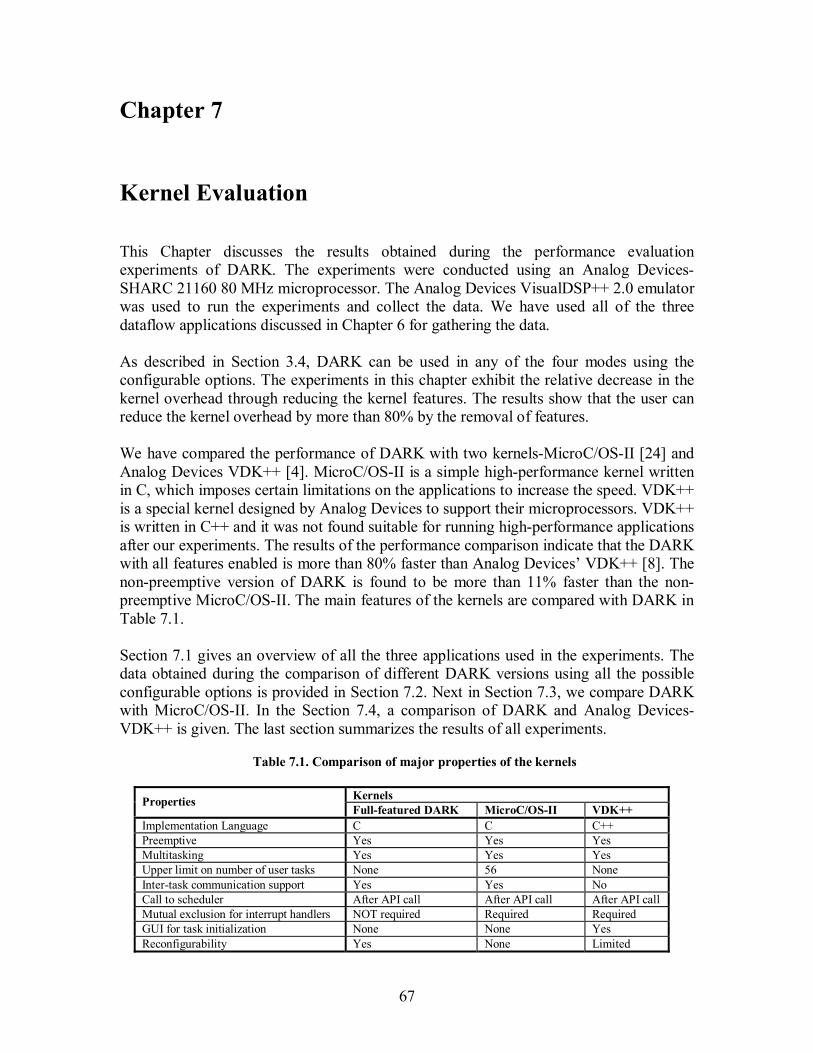
67
Chapter 7 Kernel Evaluation This Chapter discusses the results obtained during the performance evaluation experiments of DARK. The experiments were conducted using an Analog Devices-SHARC 21160 80 MHz microprocessor. The Analog Devices VisualDSP++ 2.0 emulator was used to run the experiments and collect the data. We have used all of the three dataflow applications discussed in Chapter 6 for gathering the data. As described in Section 3.4, DARK can be used in any of the four modes using the configurable options. The experiments in this chapter exhibit the relative decrease in the kernel overhead through reducing the kernel features. The results show that the user can reduce the kernel overhead by more than 80% by the removal of features. We have compared the performance of DARK with two kernels-MicroC/OS-II [24] and Analog Devices VDK++ [4]. MicroC/OS-II is a simple high-performance kernel written in C, which imposes certain limitations on the applications to increase the speed. VDK++ is a special kernel designed by Analog Devices to support their microprocessors. VDK++ is written in C++ and it was not found suitable for running high-performance applications after our experiments. The results of the performance comparison indicate that the DARK with all features enabled is more than 80% faster than Analog Devices� VDK++ [8]. The non-preemptive version of DARK is found to be more than 11% faster than the non-preemptive MicroC/OS-II. The main features of the kernels are compared with DARK in Table 7.1. Section 7.1 gives an overview of all the three applications used in the experiments. The data obtained during the comparison of different DARK versions using all the possible configurable options is provided in Section 7.2. Next in Section 7.3, we compare DARK with MicroC/OS-II. In the Section 7.4, a comparison of DARK and Analog Devices-VDK++ is given. The last section summarizes the results of all experiments.
Table 7.1. Comparison of major properties of the kernels
Kernels Properties Full-featured DARK MicroC/OS-II VDK++
Implementation Language C C C++ Preemptive Yes Yes Yes Multitasking Yes Yes Yes Upper limit on number of user tasks None 56 None Inter-task communication support Yes Yes No Call to scheduler After API call After API call After API call Mutual exclusion for interrupt handlers NOT required Required Required GUI for task initialization None None Yes Reconfigurability Yes None Limited
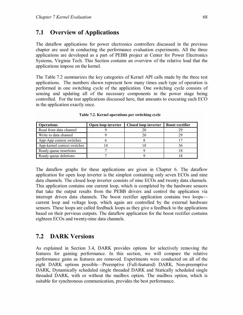
Chapter 7 Kernel Evaluation
68
7.1 Overview of Applications The dataflow applications for power electronics controllers discussed in the previous chapter are used in conducting the performance evaluation experiments. All the three applications are developed as a part of PEBB project at Center for Power Electronics Systems, Virginia Tech. This Section contains an overview of the relative load that the applications impose on the kernel. The Table 7.2 summarizes the key categories of Kernel API calls made by the three test applications. The numbers shown represent how many times each type of operation is performed in one switching cycle of the application. One switching cycle consists of sensing and updating all of the necessary components in the power stage being controlled. For the test applications discussed here, that amounts to executing each ECO in the application exactly once.
The dataflow graphs for these applications are given in Chapter 6. The dataflow application for open loop inverter is the simplest containing only seven ECOs and nine data channels. The closed loop inverter consists of nine ECOs and twenty data channels. This application contains one current loop, which is completed by the hardware sensors that take the output results from the PEBB drivers and control the application via interrupt driven data channels. The boost rectifier application contains two loops�current loop and voltage loop, which again are controlled by the external hardware sensors. These loops are called feedback loops as they give a feedback to the applications based on their pervious outputs. The dataflow application for the boost rectifier contains eighteen ECOs and twenty-nine data channels. 7.2 DARK Versions As explained in Section 3.4, DARK provides options for selectively removing the features for gaining performance. In this section, we will compare the relative performance gains as features are removed. Experiments were conducted on all of the eight DARK options possible�Preemptive (Full-featured) DARK, Non-preemptive DARK, Dynamically scheduled single threaded DARK and Statically scheduled single threaded DARK, with or without the mailbox option. The mailbox option, which is suitable for synchronous communication, provides the best performance.
Table 7.2. Kernel operations per switching cycle
Operations Open loop inverter Closed loop inverter Boost rectifier Read from data channel 9 20 29 Write to data channel 9 20 29 App-App context switches 6 8 17 App-kernel context switches 14 18 36 Ready queue insertions 7 9 18 Ready queue deletions 7 9 18

Chapter 7 Kernel Evaluation
69
0500
10001500200025003000350040004500
Mes
sage
Que
ue
Mai
lbox
Mes
sage
Que
ue
Mai
lbox
Mes
sage
Que
ue
Mai
lbox
Mes
sage
Que
ue
Mai
lbox
Full Featured Non-Preemptive
Single-threaded Dyn.
Single-threaded Stat.
Version
Inst
ruct
ion
Cyc
les Other OS operations
Data channel operations
Ready queue operations
Context switching
Dispatcher
ECO execution
Figure 7.1. Performance of DARK versions for the Open-loop Inverter application
Table 7.3. Performance of DARK versions for the open loop application with message queues
Execution time for one switching cycle (Instruction cycles) Operations
Full-featured Non-preemptive Single-threaded
dynamically scheduled Single-threaded
statically scheduled ECO execution 235 235 235 235 Scheduling 529 529 219 212 Context switching 1148 1148 0 0 Ready queue operations 525 525 525 0 Data channel operations 1304 999 945 312 Other OS operations 462 460 77 0 TOTAL 4203 3896 2001 759
Table 7.4. Performance of DARK versions for the open loop application with mailboxes
Execution time for one switching cycle (Instruction cycles) Operations
Full-featured Non-preemptive Single-threaded
dynamically scheduled Single-threaded
statically scheduled ECO execution 235 235 235 235 Scheduling 529 529 219 212 Context switching 1148 1148 0 0 Ready queue operations 525 525 525 0 Data channel operations 1040 734 734 67 Other OS operations 462 450 121 0 TOTAL 3939 3621 1834 514

Chapter 7 Kernel Evaluation
70
01000200030004000500060007000
Mes
sage
Que
ue
Mai
lbox
Mes
sage
Que
ue
Mai
lbox
Mes
sage
Que
ue
Mai
lbox
Mes
sage
Que
ue
Mai
lbox
Full Featured Non-Preemptive
DARK
Single-threaded
Dyn.
Single-threaded
Stat.
Version
Inst
ruct
ion
Cyc
les Other OS operations
Data channel operationsReady queue operationsContext switchingDispatcherECO execution
Figure 7.2. Performance of DARK versions for the Closed-loop Inverter application
Table 7.5. Performance of DARK versions for the closed loop application with message queues
Execution time for one switching cycle (Instruction cycles) Operations
Full-featured Non-preemptive Single-threaded
dynamically scheduled Single-threaded
statically scheduled ECO execution 583 583 583 583 Scheduling 679 679 297 270 Context switching 1476 1476 0 0 Ready queue operations 612 612 612 0 Data channel operations 2659 2059 2059 731 Other OS operations 594 594 203 0 TOTAL 6603 6003 3754 1584
Table 7.6. Performance of DARK versions for the closed loop application with mailboxes
Execution time for one switching cycle (Instruction cycles) Operations
Full-featured Non-preemptive Single-threaded
dynamically scheduled Single-threaded
statically scheduled ECO execution 583 583 583 583 Scheduling 679 679 297 270 Context switching 1476 1476 0 0 Ready queue operations 612 612 612 0 Data channel operations 2271 1698 1698 220 Other OS operations 594 594 181 0 TOTAL 6215 5642 3371 1073

Chapter 7 Kernel Evaluation
71
02000400060008000
100001200014000
Mes
sage
Que
ue
Mai
lbox
Mes
sage
Que
ue
Mai
lbox
Mes
sage
Que
ue
Mai
lbox
Mes
sage
Que
ue
Mai
lbox
Full Featured Non-Preemptive
DARK
Single-threaded
Dyn.
Single-threaded
Stat.
Version
Inst
ruct
ion
Cyc
les Other OS operations
Data channeloperationsReady queueoperationsContext switching
Dispatcher
Figure 7.3. Performance of DARK versions for the Boost Rectifier application
Table 7.7. Performance of DARK versions for the boost rectifier application with message queues
Execution time for one switching cycle (Instruction cycles) Operations
Full-featured Non-preemptive Single-threaded
dynamically scheduled Single-threaded
statically scheduled ECO execution 778 778 778 778 Scheduling 1354 1354 585 567 Context switching 2952 2952 0 0 Ready queue operations 1811 1811 1811 0 Data channel operations 4252 3174 3174 1020 Other OS operations 1224 1224 205 0 TOTAL 12371 11293 6553 2365
Table 7.8. Performance of DARK versions for the boost rectifier application with mailboxes
Execution time for one switching cycle (Instruction cycles) Operations
Full-featured Non-preemptive Single-threaded
dynamically scheduled Single-threaded
statically scheduled ECO execution 778 778 778 778 Scheduling 1354 1354 585 567 Context switching 2952 2952 0 0 Ready queue operations 1811 1811 1811 0 Data channel operations 3699 2640 2640 216 Other OS operations 1224 1224 88 0 TOTAL 11818 10759 5902 1561

Chapter 7 Kernel Evaluation
72
Table 7.3 shows the performance comparison figures obtained when message queues are used whereas the figures for the mailboxes are provided in Table 7.4. As shown, the full-featured version of DARK takes 4203 instruction cycles to complete one switching cycle of the application, whereas the minimal featured version with mailboxes takes only 514 instruction cycles. A significant performance gain is achieved by removing the multi-threaded feature, as the overhead for context switching diminishes drastically. In addition, static scheduling also leads to performance gain, because the ready queue and firing rule related operations are completely eliminated. The mailbox option eradicates the queue maintenance operations, because of which it is faster than the versions with message queues. The Figure 7.1 shows a graphical representation of the reduction in kernel overhead, both in message queues and mailboxes versions. Tables 7.5 and 7.6, and Figure 7.2 show the similar comparison results for the closed loop application. The full-featured DARK takes 6603 instruction cycles for completing one switching cycle of the application while the minimal featured version takes 1073 instruction cycles. At the end, we have provided the results obtained when the boost rectifier application was used to run the experiments. The data in the Tables 7.7 and 7.8 show that the full-featured DARK takes 12371 instruction cycles for executing one switching cycle of the application whereas the minimal-featured version takes only 1561 instruction cycles. The reduction in kernel overhead by removing features is shown in Figure 7.3. 7.3 DARK vs. MicroC/OS-II In this section we present the results obtained by the performance comparison of Full-featured DARK with Non-preemptive MicroC/OS-II [24]. MicroC/OS-II is a preemptive multi-tasking kernel written by Jean J. Labrosse in C. It schedules tasks based on their priorities and does not provide any special support for dataflow applications. MicroC/OS-II provides API for inter-task communication using message queues. For experimentation purposes, the support for firing rules was added for dynamic scheduling of dataflow applications. Semaphores were used to avoid race conditions related to message queues, which are shared data structures. MicroC/OS-II makes many simplifying decisions in order to provide high-performance. The number of user tasks or threads is limited to 56 and every task should have different priority. This enables the kernel to completely eliminate the costly ready queue operations. MicroC/OS-II uses bit tables for faster scheduling of tasks. On the negative side, it makes the fair scheduling of tasks impossible, as same priorities cannot be assigned to multiple tasks. The limit on number of tasks is also a concerning factor for dataflow applications because they often have more tasks than regular applications for increasing the reusability and modularity. In DARK, the number of threads is limited by the system memory and multiple threads can have the same priority, which enables fair scheduling.

Chapter 7 Kernel Evaluation
73
Unlike DARK, MicroC/OS-II does not have typed data channels. The data channels of MicroC/OS-II support only void pointers, thus reducing the type safety. This also increases the possibility of memory leaks and dangling pointers. Moreover, MicroC/OS-II does not provide any special scheduling for dataflow applications based on the data in their incoming data channels. This increases the burden on the application designers who in turn are forced to use an invariant of static scheduling for their applications. At last, the preemptive scheduling approach adopted in MicroC/OS-II is an unnecessary overhead for dataflow applications. In a dataflow application, a thread becomes ready only after some specific API functions such as read or write to data-channel or after interrupts. So, it is not necessary to check for higher-priority threads at each clock tick as is done in MicroC/OS-II. Instead this process should occur only after possible operations that can make a dataflow thread ready, which is the approach adopted in DARK. So, the
02000
400060008000
1000012000
1400016000
DARK MicroC/OS-II
DARK MicroC/OS-II
DARK MicroC/OS-II
Open loop Closed loop Boost Rectifier
Inst
ruct
ion
Cyc
les
Other OS operations
Data channel operations
Ready queue operations
Context sw itching
Scheduling
ECO execution
Figure 7.4. Performance comparison between Full-featured DARK with message queues and MicroC/OS-II
Table 7.9. Performance comparison between Full-featured DARK with message queues and MicroC/OS-II
Open loop Closed loop Boost Rectifier
Operations Non-Preemptive DARK
MicroC/OS-II
Non-Preemptive DARK
MicroC/OS-II
Non-Preemptive DARK
MicroC/OS-II
ECO execution 235 235 583 583 778 778Scheduling 529 882 679 1013 1354 2467Context switching 1148 1575 1476 2098 2952 4253Ready queue operations 525 0 612 0 1811 0Data channel operations 999 1684 2059 3674 3174 5958Other OS operations 460 0 594 0 1224 0TOTAL 3896 4376 6003 7368 11293 13456

Chapter 7 Kernel Evaluation
74
preemptive scheduling approach adopted in DARK is more effective and has lesser overhead than MicroC/OS-II, as it is designed specially for dataflow applications. The Table 7.9 and Figure 7.4 show the results obtained in the performance comparison of Non-preemptive DARK with message queues and Non-preemptive MicroC/OS-II. 7.4 DARK vs. Analog Devices-VDK++ VDK++ [4] is a preemptive multi-tasking kernel written in C++. It is provided by Analog Devices as a component of its VisualDSP++ IDE for developing applications for its DSPs. VDK++ provides users the options of selecting the scheduling policy. It supports cooperative scheduling and round robin scheduling in addition to preemptive scheduling. The associated overhead because of object-oriented features makes VDK++ unsuitable for high-performance applications. The scheduling adopted in VDK++ is similar to DARK. The scheduler is called after an API call to the kernel, which can make a higher priority thread ready. VDK++ does not provide any support for inter-task communication, which is an integral part of any kernel. For performing the experiments, we added data channel support to VDK++ similar to DARK. While accessing the data-channels, we had to use semaphores in VDK++ to avoid shared data problems. For dynamic scheduling of the dataflow applications, the event signal API provided by the VDK++ kernel was used in read and write operations. VDK++ provides a user interface for the programmers through which the properties of the kernel can be changed. The user interface is also used to add or remove events, semaphores, threads, etc. This makes the kernel easy to use but on the hand, also increases the inflexibility of the kernel. It is a drawback for the dataflow applications, which rely heavily on reusability of individual ECOs because the firing rules of existing ECOs cannot be used in a new application. The user needs to create a separate set of events for each project or application. Also, as the kernel files are generated automatically by the kernel for every project, modifying VDK++ to make it suitable for dataflow applications is very difficult and expensive. Moreover, the kernel operations in VDK++ are very heavyweight and are unsuitable for applications that require high-performance. We conclude that VDK++ is suitable for those applications that have independent threads and where the speed of execution or the kernel overhead is not a big constraint. Table 7.10 and Figure 7.5 show the results obtained in the comparison of Full-featured DARK with VDK++. As seen in the figures, the use of expensive VDK++- semaphore and event operations in data channel reads and writes increases the cost by a tremendous amount of instruction cycles.

Chapter 7 Kernel Evaluation
75
7.5 Summary of Results In this section, we have summarized the results obtained in all the experiments. The Figures 7.6, 7.7 and 7.8 present the summaries for Open-loop, Closed-loop and Boost Rectifier applications, respectively. As shown in the figures, the configurable options of DARK present opportunities to application designers for selecting a tailored version that meets the performance requirements. The figures use the same legend as used in previous figures.
Table 7.10. Performance comparison between Full-featured DARK with message queues and AnalogDevices- VDK++
Open loop Closed loop Boost Rectifier
Operations Full-featured DARK VDK++
Full-featured DARK VDK++
Full-featured DARK VDK++
ECO execution 235 235 583 583 778 778Scheduling 529 2243 679 3046 1354 5564Context switching 1148 1659 1476 2312 2952 4278Ready queue operations 525 0 612 0 1811 0Data channel operations 1304 14850 2659 33000 4252 47850Other OS operations 462 2551 594 4093 1224 7461TOTAL 4203 21538 6603 43034 12371 65931
0
10000
20000
30000
40000
50000
60000
70000
DARK VDK++ DARK VDK++ DARK VDK++
Open loop Closed loop Boost Rectif ier
Inst
ruct
ion
Cyc
les
Other OS operations
Data channel operations
Ready queue operations
Context switching
Scheduling
ECO execution
Figure 7.5. Performance comparison between Full-featured DARK with message queues and
Analog Devices-VDK++

Chapter 7 Kernel Evaluation
76
Open Loop Inverter
0
2000
4000
6000
8000
10000
12000
14000
16000
18000
20000
22000
24000
Mai
lbox
Mes
sage
Que
ue
Mai
lbox
Mes
sage
Que
ue
Mai
lbox
Mes
sage
Que
ue
Mai
lbox
Mes
sage
Que
ue
Single-threadedStat. Sch
Single-threadedDyn. Sch
Non-Preemptive Preemptive
DARK MCOS-II VDK++RTOS
Inst
ruct
ion
Cyc
les
Figure 7.6. Summary for results obtained while using Open-loop Inverter application
Closed Loop Inverter
0
5000
10000
15000
20000
25000
30000
35000
40000
45000
Mai
lbox
Mes
sage
Que
ue
Mai
lbox
Mes
sage
Que
ue
Mai
lbox
Mes
sage
Que
ue
Mai
lbox
Mes
sage
Que
ue
Single-threadedStat. Sch
Single-threadedDyn. Sch
Non-Preemptive Preemptive
DARK MCOS-II VDK++RTOS
Inst
ruct
ion
Cyc
les
Figure 7.7. Summary for results obtained while using Closed-loop Inverter application

Chapter 7 Kernel Evaluation
77
In the Chapter 8, we describe the future work and conclusions drawn by us. It contains discussion of two new versions of DARK that are under development. The Appendix contains the full source code of DARK.
Boost Rectifier
0
5000
10000
15000
20000
25000
30000
35000
40000
45000
50000
55000
60000
65000
70000
Mailbox MessageQueue
Mailbox MessageQueue
Mailbox MessageQueue
Mailbox MessageQueue
Single-threadedStat. Sch
Single-threadedDyn. Sch
Non-Preemptive Preemptive
DARK MCOS-II VDK++RTOS
Inst
ruct
ion
Cyc
les
Figure 7.8. Summary for results obtained while using Boost Rectifier application
78
Chapter 8 Conclusions and Future Work The dataflow architecture is a powerful choice for embedded systems because of its inherent modularity and support for reusability. The absence of a kernel for dataflow applications often forces the designers to avoid it when speed of execution is important. This Thesis presented the design and evaluation of a kernel specially designed for dataflow applications. The implementation of the kernel for embedded systems using Analog Devices SHARC microprocessors was also provided. We showed how the multiple register sets available on some microprocessors could be used to increase the speed of execution. The performance of the developed kernel was evaluated and compared with two commercial kernels. As the kernel was developed as a part of research project, the goal of providing a high-performance platform for embedded software was always the main focus of the work. DARK meets the goal of providing a high performance platform for dataflow applications in embedded control and is being used in power electronics controllers being developed for the PEBB project at Center for Power Electronics Systems, Virginia Tech. To summarize, this thesis makes the following contributions:
• We have described the design and implementation of DARK, an operating system kernel specially designed to support dataflow applications that have high-performance requirements.
• We have presented the concept of high-speed context switching, which is
achieved by using the dual register sets provided by some digital signal processors.
• We have shown how dataflow applications can be scheduled by using simple
structures like firing rules.
• We have explained a minimal-footprint interrupt handling approach that separates the processes of receiving and handling interrupts.
• We have shown relative performance gains achieved by selectively removing
features of the kernel.
• We have substantiated our claims of DARK�s high-performance by comparing its performance with two commercially available RTOSes.

Chapter 8 Conclusions and Future Work
79
8.1 Future Work Two new versions of DARK are envisaged to supplement performance configurability of the kernel. The first single-threaded version will rely on a static schedule, inlining of ECO functions, and elimination of virtually all data channel overhead to improve performance. The second version will add full real-time support to the kernel. The first version will thus become the fastest version of DARK whereas the second version is expected to be the slowest. An object-oriented version of DARK implemented in C++ called DARK++ [42] is also under development. A performance comparison of DARK and DARK++ will examine the additional runtime overhead incurred when an object-oriented version is used. Finally, incorporation of distributed programming support for dataflow applications executing on multiple processors is also under investigation. An algorithm for distributed allocation of ECOs on multiple DSPs has already been developed. A distributed and transparent communication system for ECOs is also under development, which will enable the ECOs allocated on different DSPs to communicate transparently. Currently, the dataflow graphs for the applications are represented as structures in DARK. A graphical tool can be developed to provide a user-interface to the application programmers, which allows drawing DFGs in a more natural way. Apart from drawing DFGs and expressing ECO and data channel information, the user interface can also help in maintaining an ECO library with select and drag operations for rapidly building a dataflow application.

80
References [1] A. Benveniste and G. Berry, �The synchronous approach to reactive and real-time
systems�, Proceedings of the IEEE, vol. 79 (9), 1991, pp. 1270-1282 [2] A. Benveniste, P. Caspi, P. Le Guernic and N. Halbwachs, �Dataflow synchronous
languages�, J.W. de Bakker, W.-P. de Roever, G. Rozenburg (Eds.), �A Decade of Concurrency-Reflections and Perspectives�, Lecture notes in Computer Science, vol. 803, Springer, Berlin, 1994, pp. 1-45.
[3] A.L. Davis and R.M. Keller, �Dataflow program graphs,� IEEE Computer, vol. 15,
no.2, Feb. 1982, pp.26-41. [4] Analog Devices, http://www.analog.com/ [5] A. Silberschatz and P.B. Galvin, �Operating System Concepts�, Fifth Edition, John
Wiley & Sons, 2000. [6] C. Kim and J.-L. Gaudiot, �Dataflow and Multithreaded Architectures�, Encyclopedia
of Electricala dn Electronics Engineering, Wiley, New York, 1997. [7] C.L. Liu and J.W. Layland, �Scheduling Algorithms for Multiprogramming in a
Hard-Real-Time Environment�, Journal of the ACM, Vol. 20, No. 1, pp. 46-61. [8] D.E. Culler, �Dataflow architectures,� Annual Review of Computer Science, vol. 1,
Annual Reviews Inc., Palo Alto, CA, 1986. [9] D. Garlan and M. Shaw, �An introduction to software architecture,� in Advances in
Software Engineering and Knowledge Engineering, vol. I, World Scientific Publishing Co., New Jersey, 1993.
[10] D. Hildebrand, �An architectural overview of QNX,� in Proc. USENIX Workshop on
Micro-kernels and Other Kernel Architectures, Seattle, WA, Apr. 1992, pp. 113-126.
[11] E.A. Lee, �Consistency in dataflow graphs�, IEEE Trans. Parallel Distributed Syst. 2
(2) (1991). [12] E.A. Lee and D.G. Messerschmitt, �Static scheduling of synchronous dataflow
programs for digital signal processing�, IEEE Trans. Comput. (1987). [13] E.A. Lee and T.M. Parks, �Dataflow process networks�, Proc. IEEE 83 (5) (1995)
773-801.

References
81
[14] G. Kahn, �The semantics of a simple language for parallel programming�, Proceeding of the IFIP Congress 74, North-Holland, Amsterdam, 1974.
[15] J.B. Dennis and G.R. Gao, �Multithreaded architectures: principles, projects and
issues�, ACAPS Technical Memo 29, School of Computer Science, McGill University, Montreal, Que., February 1994, ftp://ftp-acaps.cs.mcgill.ca/pub/doc/memos.
[16] G.R. Gao, L. Bic and J-L. Gaudiot (Eds.), �Advanced Topics in Dataflow
Computing and Multithreading�, IEEE Computer Soc. Press, New York, 1995, book contains papers presented at the Second International Workshop on Dataflow Computers, Hamilton Island, Australia, May 1992.
[17] J. B. Dennis, �Dataflow idea for supercomputers�, Digest of papers, COMPCON
Spring �84, San Francisco, CA, February-March 1984, pp. 15-19 [18] J. B. Dennis, �First version of a dataflow procedure language�, Proc. Colloque sur la
Programmation, Springer-Verlag Lecture Notes in Computer Science, Vol. 19, 1974, pp. 362-376.
[19] J.B. Dennis, �Streams data types for signal processing�, in: J.L. Gaudiot and L. Bic (
Eds.), �Advanced Topics in Dataflow Computing and Multithreading�, Prentice-Hall, Englewood Cliffs, NJ, 1995.
[20] J. Guo, S. Edwards, and D. Boroyevich. �Elementary control objects: Toward a
dataflow architecture for power electronics control software." In Proc. IEEE 33rd Annual Power Electronics Specialists Conf. (PESC 2001), June 2002.
[21] Jinghong Guo, Stephen Edwards, Dushan Boroyevich, "Improved architecture of
PEBB plug and play power electronics systems: Elementary control object (ECO) and dataflow", CPES 2001 Power Electronics Seminar and NSF/Industry Annual Review; April 2001.
[22] Jinghong Guo, Stephen H. Edwards, and Dushan Borojevich, �Implementing
dataflow-based control software for power electronics�, In Proceedings of the IEEE 9th Workshop on Computers in Power Electronics (COMPEL), 2002.
[23] Jinghong Guo, Stephen H. Edwards, and Dushan Borojevich, �Software Structure of
the PEBB-based Plug ad Play Power Electronics Systems,� 16th IEEE Applied Power Electronics Conference and Exposition, Anaheim, CA, 2000.
[24] J.J. Labrosse, MicroC/OS-II, The Real-time Kernel, R & D Books, Oct. 1998. [25] J.P. Lehoczky, L. Sha, and Y. Ding, �The rate monotonic scheduling algorithm:
Exact characterization and average case behavior,� IEEE Real-Time Systems Symposium, pages 166-171, December 1989.

References
82
[26] J.T. Buck, �Scheduling dynamic dataflow graphs with bounded memory using the
token flow model�, Technical Report UCB/ERL 93/69, Ph.D. Dissertation, Department of EECS, University of California, Berkeley, CA 94720, 1993.
[27] J.T. Buck, �Static scheduling and code generation from dynamic dataflow graphs
with integer valued control systems�, Proceedings of the IEEE Asilomar Conference on Signals, Systems and Computers, 31 October-2 November, Pacific Grove, CA, 1994.
[28] J.T. Buck and E.A. Lee, �Scheduling dynamic dataflow graphs with bounded
memory using the token flow model�, Proceedings of the IEEE International Conference on Acoustics, Speech, and Signal Processing, vol. I, Minneapolis, MN, April 1993, pp. 429-432.
[29] K. Jeffay, �Analysis of a Synchronization and Scheduling Discipline for Real-Time
Tasks with Preemption Constraints�, Proc. Tenth IEEE Real-Time systems Symposium, Santa Monica, CA, December 1989, pp. 295-305.
[30] K. Jeffay, �Scheduling Sporadic Tasks With Shared Resources in Hard-Real-Time
systems�, University of North Carolina at Chapel Hill, Department of Computer Science, Technical Report TR90-038, August 1990.
[31] K. Jeffay, D.L. Stone, and D. Poirier, �YARTOS: Kernel support for efficient,
predictable real-time systems,� in Proc. Joint of Eighth IEEE Workshop on Real-Time Operating Systems and Software and IFAC/IFIP Workshop on Real-Time Programming. Atlanta, GA. Vol. 7, No. 4, Fall 1991 pp. 8-13.
[32] K.M. Zuberi and K.G. Shin, �EMERALDS: A microkernel for embedded real-time
systems,� in Proc. Real-Time Technology and Applications Symp., pp. 241-249, 1996.
[33] Manual for Analog Devices SHARC Processors-2106X, http://www.analog.com [34] Milan Milenkovic, �Operating systems: Concepts and Design�, McGraw-Hill Book
Company, 1987. [35] N. Halbwachs, �Synchronous Programming of Reactive Systems�, Kluwer
Academic Publishers, Dordrecht, 1993.
[36] N. Halbwachs, P. Caspi, P. Raymond and P. Pilaud, �The synchronous dataflow programming language LUSTRE�, Proceedings of the IEEE, vol. 79 (9), pp. 1305-1319.
[37] N. Wirth, �Toward a discipline of real-time programming�, CACM, Vol. 20, No. 8,
577-583.
References
83
[38] P. Le Guernic, T. Gauthier, M. Le Borgne and C.L. Maire, �Programming real-time
applications with SIGNAL�, Proc. IEEE 79 (9) (1991). [39] Power Electronics Building Blocks (PEBB) Research Group website, http://web-
cat.cs.vt.edu/PEBB/ [40] R.A. Iannucci, G.R. Gao, R.H. Halstead Jr. and B. Smith (Eds.), �Multithreaded
Computer Architecture: A Summary of the State of the Art�, Kluwer Academic Publishers, Norwell, Massachusetts, 1994, book contains papers presented at the Workshop on Multithreaded Computers, Albuquerque, New Mexico, November 1991.
[41] R. S. Pressman, �Software Engineering: A Practitioner�s Approach�, fifth edition,
McGraw-Hill Series in Computer Science. [42] Sumithra Bhakthavatsalam and Stephen H. Edwards. "Applying object-oriented
techniques in embedded software design," CPES 2002 Power Electronics Seminar and NSF/Industry Annual Review, April, 2002.
[43] Walid A. Najjar, Edward A. Lee, and Guang R. Gao, �ADVANCES IN THE
DATAFLOW COMPUTATIONAL MODEL�, Parallel Computing, Volume 25, 1999, pp. 1907-1929
[44] Wind River VSPWorks, technical brief http://www.windriver.com/pdf/vspworks_tb.pdf

84
Appendix A Code listing /*==========================================================================*\ | DFG.h *--------------------------------------------------------------------------* | This is the application designer's primary header file. It defines the | necessary structures for specifying an ECO-based application as a | dataflow graph of ECO instances. \*==========================================================================*/ #ifndef DFG_H #define DFG_H 1 /*==========================================================================*\ | DFG Nodes \*==========================================================================*/ typedef struct { ECO eco; ECO_Configuration configuration; Firing_Rule *firing_rules; int firing_rule_name; Priority initial_priority; Firing_Mask default_mask; unsigned int assigned_processor; } DFG_Node; /* Used to terminate the node definition */ #define NODE_TERMINATOR { NULL, NULL, NULL, -1, -1 } /* Macro to determine node termination */ #define NODE_TERMINATED(N)\ ( N.eco == NULL && N.configuration == NULL && N.firing_rules == NULL &&\ N.firing_rule_name == -1 && N.initial_priority == -1) /*==========================================================================*\ | DFG Edges \*==========================================================================*/ /* Enumeration that enables selecting an action when a queue is full */ typedef enum { OS_Block = 0 , OS_Overwrite_Newest , OS_Overwrite_Oldest } Overflow_Style; typedef short int Node_Number; typedef short int Port_Number; typedef struct { Type_Tag type; Node_Number source; Port_Number source_out_port; Node_Number sink; Port_Number sink_in_port; Overflow_Style overflow_style; unsigned int size; Array_Descriptor array_dimensions;

Appendix A Code Listing
85
bool interrupt_driven; void* ISR_signal_value; unsigned int update_frequency; } DFG_Edge; /* Used to terminate the edge definition */ #define EDGE_TERMINATOR { Type_Undefined, -1, -1, -1, -1, OS_Block, 0, 0,\ false, 0 } /* Macro to determine edge termination */ #define EDGE_TERMINATED(E) ( E.source == -1 && E.source_out_port == -1 &&\ E.sink == -1 && E.sink_in_port == -1 ) /*==========================================================================*\ | To specify the static real-time scheduler used \*==========================================================================*/ typedef void (*SCHEDULER)(void); #ifndef APPL extern DFG_Node DFG_Node_Set[]; extern DFG_Edge DFG_Edge_Set[]; extern SCHEDULER scheduler_routine; #endif /*--------------------------------------------------------------------------*/ #endif /* DFG_H */ /*--------------------------------------------------------------------------*/
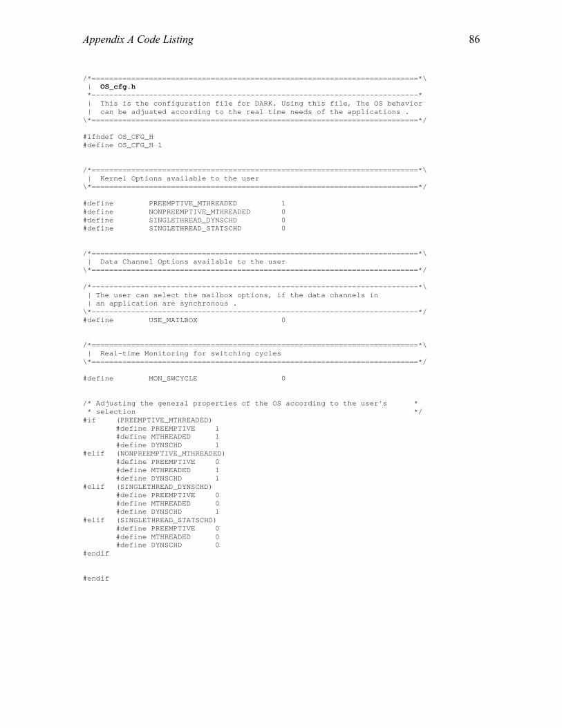
Appendix A Code Listing
86
/*==========================================================================*\ | OS_cfg.h *--------------------------------------------------------------------------* | This is the configuration file for DARK. Using this file, The OS behavior | can be adjusted according to the real time needs of the applications . \*==========================================================================*/ #ifndef OS_CFG_H #define OS_CFG_H 1 /*==========================================================================*\ | Kernel Options available to the user \*==========================================================================*/ #define PREEMPTIVE_MTHREADED 1 #define NONPREEMPTIVE_MTHREADED 0 #define SINGLETHREAD_DYNSCHD 0 #define SINGLETHREAD_STATSCHD 0 /*==========================================================================*\ | Data Channel Options available to the user \*==========================================================================*/ /*--------------------------------------------------------------------------*\ | The user can select the mailbox options, if the data channels in | an application are synchronous . \*--------------------------------------------------------------------------*/ #define USE_MAILBOX 0 /*==========================================================================*\ | Real-time Monitoring for switching cycles \*==========================================================================*/ #define MON_SWCYCLE 0 /* Adjusting the general properties of the OS according to the user's * * selection */ #if (PREEMPTIVE_MTHREADED) #define PREEMPTIVE 1 #define MTHREADED 1 #define DYNSCHD 1 #elif (NONPREEMPTIVE_MTHREADED) #define PREEMPTIVE 0 #define MTHREADED 1 #define DYNSCHD 1 #elif (SINGLETHREAD_DYNSCHD) #define PREEMPTIVE 0 #define MTHREADED 0 #define DYNSCHD 1 #elif (SINGLETHREAD_STATSCHD) #define PREEMPTIVE 0 #define MTHREADED 0 #define DYNSCHD 0 #endif #endif
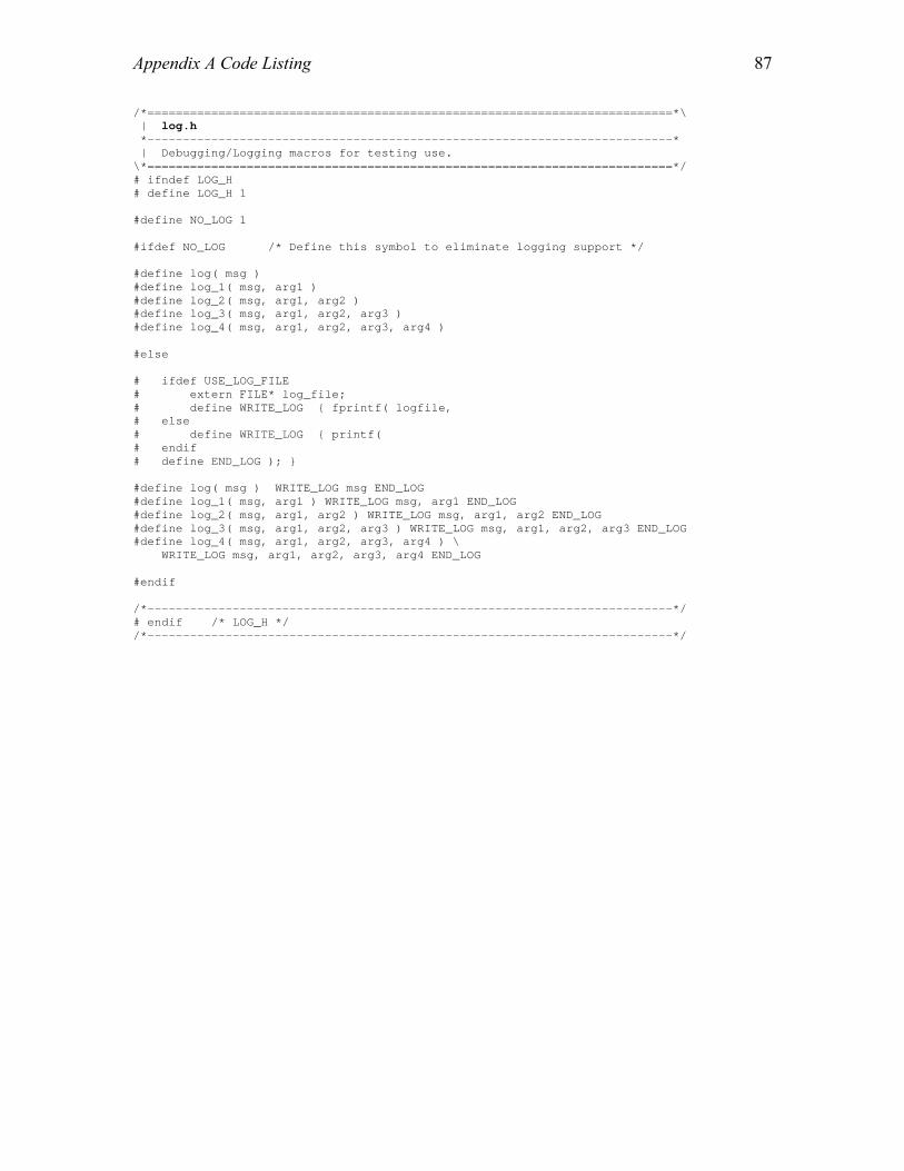
Appendix A Code Listing
87
/*==========================================================================*\ | log.h *--------------------------------------------------------------------------* | Debugging/Logging macros for testing use. \*==========================================================================*/ # ifndef LOG_H # define LOG_H 1 #define NO_LOG 1 #ifdef NO_LOG /* Define this symbol to eliminate logging support */ #define log( msg ) #define log_1( msg, arg1 ) #define log_2( msg, arg1, arg2 ) #define log_3( msg, arg1, arg2, arg3 ) #define log_4( msg, arg1, arg2, arg3, arg4 ) #else # ifdef USE_LOG_FILE # extern FILE* log_file; # define WRITE_LOG { fprintf( logfile, # else # define WRITE_LOG { printf( # endif # define END_LOG ); } #define log( msg ) WRITE_LOG msg END_LOG #define log_1( msg, arg1 ) WRITE_LOG msg, arg1 END_LOG #define log_2( msg, arg1, arg2 ) WRITE_LOG msg, arg1, arg2 END_LOG #define log_3( msg, arg1, arg2, arg3 ) WRITE_LOG msg, arg1, arg2, arg3 END_LOG #define log_4( msg, arg1, arg2, arg3, arg4 ) \ WRITE_LOG msg, arg1, arg2, arg3, arg4 END_LOG #endif /*--------------------------------------------------------------------------*/ # endif /* LOG_H */ /*--------------------------------------------------------------------------*/

Appendix A Code Listing
88
/*==========================================================================*\ | OS_init.h *--------------------------------------------------------------------------* | This is the kernel's main header file . It defines the necessary | structures to be used in the kernel . It has the structure definitions | for the thread control blocks and data channels along with definitions | for event queues and waiting queues . | \*==========================================================================*/ # ifndef OS_INIT_H # define OS_INIT_H 1 #include "DFG.h" #define MAX_LENGTH_WAITING_Q 16 #define MAX_LENGTH_EVENT_Q 16 /*==========================================================================*\ | ECO Process Run-time Info *--------------------------------------------------------------------------* | The following structures are used to maintain the runtime information of | the ECOs . They include structure for saving the runtime context of a | thread as well as a data structure called Thread Control Block for | storing the complete information about a thread . \*==========================================================================*/ /*--------------------------------------------------------------------------*\ | Thread Context *--------------------------------------------------------------------------* | This structure is used to save the context of a thread during context | switching. | The registers stored (in sequence) are: | Data registers: | MODE1 | R1,R2,R3,R5, R6,R7,R9,R10, R11,R13,R14,R15 | DAG: | BO,IO,MO,LO, B1,I1,M1,L1, B2,I2,M2,L2, B3,I3,M3,L3 | B5,I5,L5, B6,I6,L6, B7,I7,L7 | SPECIAL REG: | PCSTKP, LADDR | INSTRUCTION POINTER: | I12 \*--------------------------------------------------------------------------*/ typedef struct { int mode1; int r_reg[12]; int dag1_reg[25]; int spec_reg[2]; int ip_reg; } Context; /*--------------------------------------------------------------------------*\ | Process_State *--------------------------------------------------------------------------* | This enumeration contains all the six states of a thread . \*--------------------------------------------------------------------------*/ typedef volatile enum { ready //Thread ready to execute , blocked //Thread blocked on read or write operation , wait_for_fire //Thread blocked on wait_to_fire operation , timed_wait //Thread delayed without firing rule , timed_wait_for_fire //Thread delayed with firing rule , dead //Thread finished execution } Process_State;
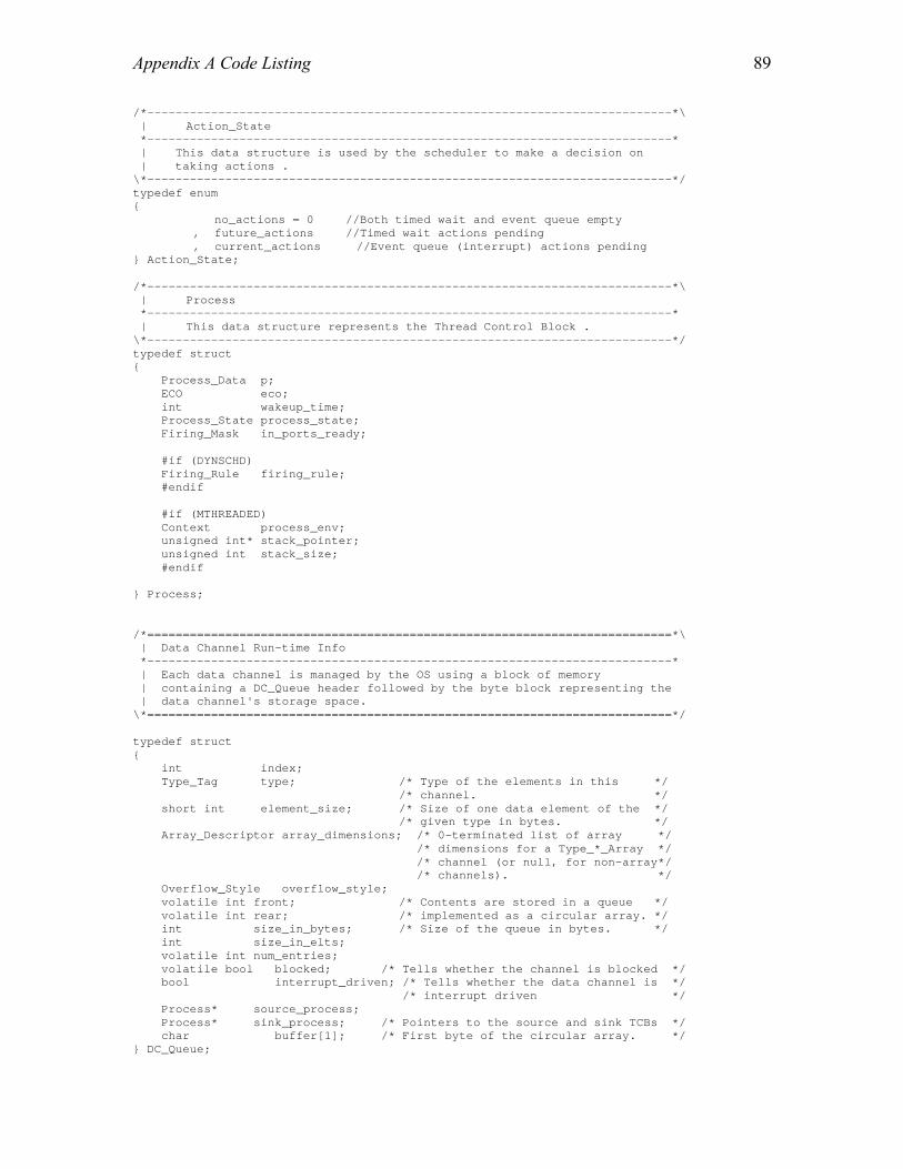
Appendix A Code Listing
89
/*--------------------------------------------------------------------------*\ | Action_State *--------------------------------------------------------------------------* | This data structure is used by the scheduler to make a decision on | taking actions . \*--------------------------------------------------------------------------*/ typedef enum { no_actions = 0 //Both timed wait and event queue empty , future_actions //Timed wait actions pending , current_actions //Event queue (interrupt) actions pending } Action_State; /*--------------------------------------------------------------------------*\ | Process *--------------------------------------------------------------------------* | This data structure represents the Thread Control Block . \*--------------------------------------------------------------------------*/ typedef struct { Process_Data p; ECO eco; int wakeup_time; Process_State process_state; Firing_Mask in_ports_ready; #if (DYNSCHD) Firing_Rule firing_rule; #endif #if (MTHREADED) Context process_env; unsigned int* stack_pointer; unsigned int stack_size; #endif } Process; /*==========================================================================*\ | Data Channel Run-time Info *--------------------------------------------------------------------------* | Each data channel is managed by the OS using a block of memory | containing a DC_Queue header followed by the byte block representing the | data channel's storage space. \*==========================================================================*/ typedef struct { int index; Type_Tag type; /* Type of the elements in this */ /* channel. */ short int element_size; /* Size of one data element of the */ /* given type in bytes. */ Array_Descriptor array_dimensions; /* 0-terminated list of array */ /* dimensions for a Type_*_Array */ /* channel (or null, for non-array*/ /* channels). */ Overflow_Style overflow_style; volatile int front; /* Contents are stored in a queue */ volatile int rear; /* implemented as a circular array. */ int size_in_bytes; /* Size of the queue in bytes. */ int size_in_elts; volatile int num_entries; volatile bool blocked; /* Tells whether the channel is blocked */ bool interrupt_driven; /* Tells whether the data channel is */ /* interrupt driven */ Process* source_process; Process* sink_process; /* Pointers to the source and sink TCBs */ char buffer[1]; /* First byte of the circular array. */ } DC_Queue;
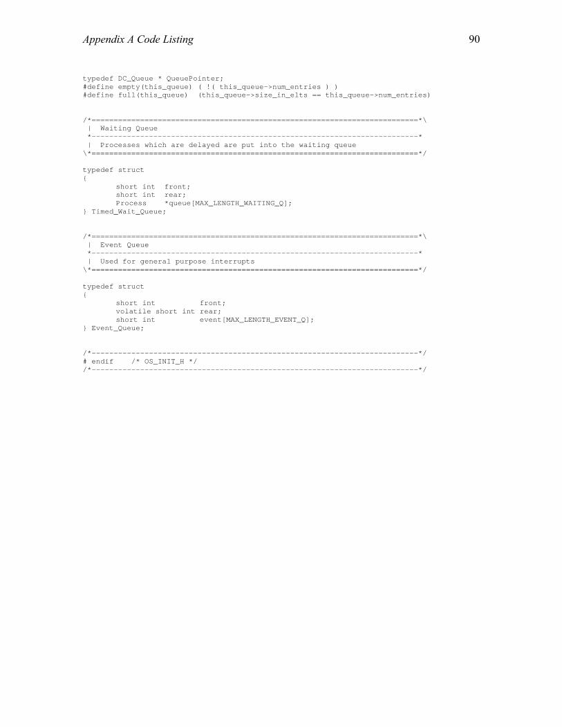
Appendix A Code Listing
90
typedef DC_Queue * QueuePointer; #define empty(this_queue) ( !( this_queue->num_entries ) ) #define full(this_queue) (this_queue->size_in_elts == this_queue->num_entries) /*==========================================================================*\ | Waiting Queue *--------------------------------------------------------------------------* | Processes which are delayed are put into the waiting queue \*==========================================================================*/ typedef struct { short int front; short int rear; Process *queue[MAX_LENGTH_WAITING_Q]; } Timed_Wait_Queue; /*==========================================================================*\ | Event Queue *--------------------------------------------------------------------------* | Used for general purpose interrupts \*==========================================================================*/ typedef struct { short int front; volatile short int rear; short int event[MAX_LENGTH_EVENT_Q]; } Event_Queue; /*--------------------------------------------------------------------------*/ # endif /* OS_INIT_H */ /*--------------------------------------------------------------------------*/
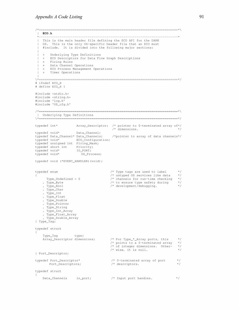
Appendix A Code Listing
91
/*==========================================================================*\ | ECO.h *--------------------------------------------------------------------------* | This is the main header file defining the ECO API for the DARK | OS. This is the only OS-specific header file that an ECO must | #include. It is divided into the following major sections: | | + Underlying Type Definitions | + ECO Descriptors for Data Flow Graph Descriptions | + Firing Rules | + Data Channel Operations | + ECO Process Management Operations | + Timer Operations | \*==========================================================================*/ # ifndef ECO_H # define ECO_H 1 #include <stdio.h> #include <string.h> #include "log.h" #include "OS_cfg.h" /*==========================================================================*\ | Underlying Type Definitions \*==========================================================================*/ typedef int* Array_Descriptor; /* pointer to 0-terminated array of*/ /* dimensions. */ typedef void* Data_Channel; typedef Data_Channel* Data_Channels; /*pointer to array of data channels*/ typedef void* ECO_Configuration; typedef unsigned int Firing_Mask; typedef short int Priority; typedef void* IO_PORT; typedef void* OS_Process; typedef void (*EVENT_HANDLER)(void); typedef enum /* Type tags are used to label */ { /* untyped OS services like data */ Type_Undefined = 0 /* channels for run-time checking */ , Type_Byte /* to ensure type safety during */ , Type_Bool /* development/debugging. */ , Type_Char , Type_Int , Type_Float , Type_Double , Type_Pointer , Type_String , Type_Int_Array , Type_Float_Array , Type_Double_Array } Type_Tag; typedef struct { Type_Tag type; Array_Descriptor dimensions; /* For Type_*_Array ports, this */ /* points to a 0-terminated array */ /* of integer dimensions. Other- */ /* wise, it is null. */ } Port_Descriptor; typedef Port_Descriptor* /* 0-terminated array of port */ Port_Descriptors; /* descriptors. */ typedef struct { Data_Channels in_port; /* Input port handles. */

Appendix A Code Listing
92
Data_Channels out_port; /* Output port handles. */ ECO_Configuration config; /* ECO-defined block of */ /* configuratation parameters. */ volatile Firing_Mask wakeup_call; /* The last firing mask used to */ /* wake up a sleeping ECO. */ volatile Priority current_priority; /* The ECO's current priority, */ /* which should only be changed */ /* using set_priority(). */ } Process_Data; /*==========================================================================*\ | ECO Descriptors for Data Flow Graph Descriptions \*==========================================================================*/ typedef void ( *ECO_Implementation )( Process_Data* p ); typedef struct { ECO_Implementation eco; /* A pointer to the ECO's */ /* implementation function. */ Port_Descriptors in_port_types; Port_Descriptors out_port_types; unsigned int stack_size; /* internal stack size for the ECO */ unsigned int eco_weight; /* time required for ECO execution */ } ECO_Descriptor; typedef ECO_Descriptor* ECO; /* Provided by a library ECO to be */ /* used in DFG descriptions to */ /* identify that ECO. */ /*==========================================================================*\ | Firing Rules \*==========================================================================*/ typedef struct { Firing_Mask mask; /* Input ports to watch. */ Priority priority; /* New priority to switch to when */ /* this mask is triggered. */ } Priority_Firing_Mask; typedef Priority_Firing_Mask* Firing_Rule; #define DEFAULT 0 /* Name of default firing rule */ #define FIRING_MASK_TERMINATOR {0x0, -1} #define FIRING_MASK_TERMINATED(M)\ ( M->priority == -1) /*==========================================================================*\ | Data Channel Operations \*==========================================================================*/ /* These header files are needed for inlined definitions of data channel operations */ #include "OS_init.h" /*--------------------------------------------------------------------------*\ | Other Data Channel Operations *--------------------------------------------------------------------------* | size_of_DC() returns the total number of objects a data channel can hold | (or number of bytes, for string- or byte-based channels). | | entries_in_DC() returns the number of objects currently stored in the | channel. | | available_capacity_of_DC() returns the number of "empty slots" in the | channel (size - entries).

Appendix A Code Listing
93
| | flush_DC() removes items from the front of the data channel's queue | (i.e., oldest first). Its num_entries parameter indicates how many | objects to remove (or how many bytes, for string- or byte-based | channels). If num_entries is zero, all items will be flushed from the | data channel, no matter how many it currently contains. | Macros for all the functions are defined in the header file included | below . \*--------------------------------------------------------------------------*/ #include "other_DC.h" /*--------------------------------------------------------------------------*\ | Reading From Input Data Channels *--------------------------------------------------------------------------* | All of the read_*_DC() operations take an input data channel to read from | and a pointer to an ECO-owned variable/buffer where the data read is to | be placed. With the exception of read_bytes_DC(), all of the read | functions read a single value of the corresponding type. | | Data channels are managed as fixed-size queues. A read operation removes | one object from the front of this queue. | | read_bytes_DC() takes a third parameter indicating how many bytes to | read. For a data channel carrying bytes, use entries_in_DC() to find out | how many are available. | | The read_*_array_DC() operations operate on data channels carrying array | objects. | | If a data channel does not contain enough data to complete a read | request, the read_*_DC() operation will block until data becomes | available. To avoid blocking, use entries_in_DC() before reading or use | firing mask. \*--------------------------------------------------------------------------*/ /* Read macros are defined in this header file */ #include "read_DC.h" /*--------------------------------------------------------------------------*\ | Writing to Output Data Channels *--------------------------------------------------------------------------* | The write_*_DC() operations are the duals of their read_*_DC() counter- | parts. All of the notes above about using read_*_DC() operations apply | here as well. | | When a data channel is full, a write_*_DC() operation on the channel may | block, depending on the properties of the channel. See the description | of Overflow_Style in DFG.h for more details. \*--------------------------------------------------------------------------*/ /* Write macros are defined in this header file */ #include "write_DC.h" /*==========================================================================*\ | ECO Process Management Operations *--------------------------------------------------------------------------* | wait_to_fire() is normally called at the top of an ECO's main loop. It | puts the process to sleep until one of the firing masks in the ECO's | current firing rule is triggered. It then sets p->wakeup_call to the | triggered mask, updates the ECO's priority to the priority associated | with the triggered mask, and awakens the ECO by returning true. | | set_priority() can be used within an ECO to directly change its current | priority. It is more typical for an ECO's priority to be updated | automatically when it is awakened using a priority firing mask. | | wait() suspends a process for the specified duration. Normally, the

Appendix A Code Listing
94
| process will remain suspendd for a time period >= to the given delay | parameter. While the process is suspended, however, its firing rule | remains active, and the process will awaken before the delay expires if | input satisfying the firing rule arrives. \*==========================================================================*/ typedef unsigned int Time; #if (MTHREADED) bool wait_to_fire( void ); #else #define wait_to_fire( ) false #endif void set_priority( Process_Data* p, Priority new_priority ); void wait ( Process_Data* p, Time delay ); /*==========================================================================*\ | Timer Operations *--------------------------------------------------------------------------* | Definitions and routing prototypes for the timer \*==========================================================================*/ typedef unsigned int Timer; Time read_timer( Timer t ); void reset_timer( Timer t ); void set_timer( Timer t, Time new_time ); void set_timer_direction( Timer t, bool count_up ); /*--------------------------------------------------------------------------*/ # endif /* ECO_H */ /*--------------------------------------------------------------------------*/

Appendix A Code Listing
95
/*==========================================================================*\ | other_DC.h *--------------------------------------------------------------------------* | Inline/macro definitions of other DC operations . Description of all the | macros is given in ECO.h . \*==========================================================================*/ # ifndef OTHER_DC_H # define OTHER_DC_H 1 #define size_of_DC(dc) ( ((QueuePointer)dc)->size_in_elts ) #define entries_in_DC(dc) ( ((QueuePointer)dc)->num_entries ) #define bytes_in_DC(dc) ( (((QueuePointer)dc)->front < \ ((QueuePointer)dc)->rear) ? \ (((QueuePointer)dc)->rear - \ ((QueuePointer)dc)->front ) : \ (((QueuePointer)dc)->size_in_bytes + \ ((QueuePointer)dc)->rear - \ ((QueuePointer)dc)->front ) ) #define available_capacity_of_DC(dc) \ ( ((QueuePointer)dc)->size_in_elts - \ ((QueuePointer)dc)->num_entries ) #define flush_DC(dc) ( ((QueuePointer)dc)->front = \ ((QueuePointer)dc)->rear = \ ((QueuePointer)dc)->num_entries = 0 ) /*--------------------------------------------------------------------------*/ # endif /* OTHER_DC_H */ /*--------------------------------------------------------------------------*/

Appendix A Code Listing
96
/*==========================================================================*\ | read_DC.h *--------------------------------------------------------------------------* | This header file defines the macros that are used to read from data | channels and mailboxes . \*==========================================================================*/ # ifndef READ_DC_H # define READ_DC_H 1 #include "OS_cfg.h" extern volatile int ready_queue_size; /* the ready heap size */ extern Process *current_process; extern volatile Action_State actions_pending; extern Process **ready_queue; /*--------------------------------------------------------------------------*\ | READ_GOTO_OS *--------------------------------------------------------------------------* | This macro transfers the control to the kernel scheduler after a read | operation in case of preemptive DARK . \*--------------------------------------------------------------------------*/ #if (PREEMPTIVE) #define READ_GOTO_OS( qptr ) \ { \ log( "read_typed_object: checking pending actions\n" ); \ if ( actions_pending != no_actions || \ ( ( (ready_queue_size > 0) && \ (current_process->p).current_priority <= \ (ready_queue[1]->p).current_priority) ) ) \ { \ \ log( "read_typed_object: transferring to OS\n" ); \ if ( shallow_setjmp( &(current_process->process_env) ) == 0 )\ { \ shallow_longjmp( &OS_env ); \ } \ } \ } #else #define READ_GOTO_OS( qptr ) #endif /*--------------------------------------------------------------------------*\ | BLOCK_ON_READ *--------------------------------------------------------------------------* | This macro sends the thread into blocked state if the data channel is | empty . \*--------------------------------------------------------------------------*/ /* Block on read only meaningful for the dynamically scheduled DARK */ #if (DYNSCHD) #define BLOCK_ON_READ(qptr) \ { \ while ( empty(qptr) ) \ { \ log( "read_typed_object: empty mailbox, blocking\n" ); \ qptr->blocked = true; \ swap( blocked ); \ } \ } #else #define BLOCK_ON_READ( qptr )
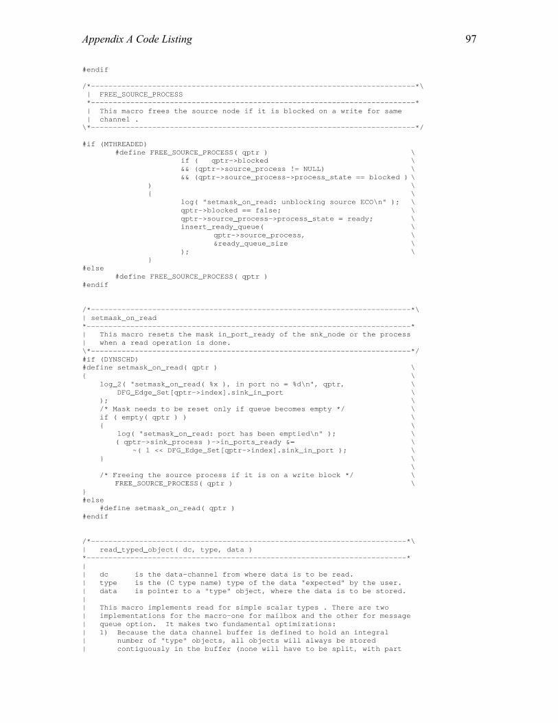
Appendix A Code Listing
97
#endif /*--------------------------------------------------------------------------*\ | FREE_SOURCE_PROCESS *--------------------------------------------------------------------------* | This macro frees the source node if it is blocked on a write for same | channel . \*--------------------------------------------------------------------------*/ #if (MTHREADED) #define FREE_SOURCE_PROCESS( qptr ) \ if ( qptr->blocked \ && (qptr->source_process != NULL) \ && (qptr->source_process->process_state == blocked ) \ ) \ { \ log( "setmask_on_read: unblocking source ECO\n" ); \ qptr->blocked == false; \ qptr->source_process->process_state = ready; \ insert_ready_queue( \ qptr->source_process, \ &ready_queue_size \ ); \ } #else #define FREE_SOURCE_PROCESS( qptr ) #endif /*-------------------------------------------------------------------------*\ | setmask_on_read *--------------------------------------------------------------------------* | This macro resets the mask in_port_ready of the snk_node or the process | when a read operation is done. \*-------------------------------------------------------------------------*/ #if (DYNSCHD) #define setmask_on_read( qptr ) \ { \ log_2( "setmask_on_read( %x ), in port no = %d\n", qptr, \ DFG_Edge_Set[qptr->index].sink_in_port \ ); \ /* Mask needs to be reset only if queue becomes empty */ \ if ( empty( qptr ) ) \ { \ log( "setmask_on_read: port has been emptied\n" ); \ ( qptr->sink_process )->in_ports_ready &= \ ~( 1 << DFG_Edge_Set[qptr->index].sink_in_port ); \ } \ \ /* Freeing the source process if it is on a write block */ \ FREE_SOURCE_PROCESS( qptr ) \ } #else #define setmask_on_read( qptr ) #endif /*------------------------------------------------------------------------*\ | read_typed_object( dc, type, data ) *-------------------------------------------------------------------------* | | dc is the data-channel from where data is to be read. | type is the (C type name) type of the data "expected" by the user. | data is pointer to a "type" object, where the data is to be stored. | | This macro implements read for simple scalar types . There are two | implementations for the macro-one for mailbox and the other for message | queue option. It makes two fundamental optimizations: | 1) Because the data channel buffer is defined to hold an integral | number of "type" objects, all objects will always be stored | contiguously in the buffer (none will have to be split, with part

Appendix A Code Listing
98
| on the trailing edge of the buffer and the remainder on the leading | edge). | 2) Transferring a value of "type" can be done more cheaply with a | single assignment statement than with memcpy, because the objects | are so small. | | Also (not really fundamental, but may save an instruction or two): | 3) since the type is coming in as a macro parameter, we can use the | compile-time constant sizeof(type) instead of retrieving it from | the queue's element_size field. \*------------------------------------------------------------------------*/ #if (USE_MAILBOX) #define read_typed_object( dc, type, data ) \ { \
QueuePointer qptr = (QueuePointer) dc; \ log_1( "\nread_typed_object( %x )\n", dc ); \
\ BLOCK_ON_READ(qptr) \ \ log( "read_typed_object: transferring data\n" ); \ *data = *(type*)(qptr->buffer); \ qptr->num_entries = 0; \ /*resetting the mask */ \ setmask_on_read( qptr ); \ READ_GOTO_OS( qptr ) \ } #else #define read_typed_object( dc, type, data ) \ { \ QueuePointer qptr = (QueuePointer) dc; \ int local_front; \ log_1( "\nread_typed_object( %x )\n", dc ); \ \ BLOCK_ON_READ(qptr) \ \ local_front = qptr->front; \ log( "read_typed_object: transferring data\n" ); \ *data = *(type*)(qptr->buffer + local_front); \ local_front = ( local_front + sizeof(type) ); \ if ( local_front == qptr->size_in_bytes) \ { \ local_front = 0; \ } \ qptr->num_entries--; \ \ qptr->front = local_front; \ \ setmask_on_read( qptr ); \ \ /* Switch to OS to see if any higher proirity process is ready or */ \ /* action is pending */ \ READ_GOTO_OS( qptr ) \ } #endif /*------------------------------------------------------------------------*\ | API macro definitions *-------------------------------------------------------------------------*/ #define read_bool_DC( dc, data ) \ read_typed_object( dc, bool, data ) #define read_char_DC( dc, data ) \ read_typed_object( dc, char, data ) #define read_int_DC( dc, data ) \ read_typed_object( dc, int, data ) #define read_float_DC( dc, data ) \

Appendix A Code Listing
99
read_typed_object( dc, float, data ) #define read_double_DC( dc, data ) \ read_typed_object( dc, double, data ) #define read_pointer_DC( dc, data ) \ read_typed_object( dc, (void*), data ) #define read_bytes_DC( dc, data, length ) \ read_raw_bytes( dc, Type_Byte, data, length ) #define read_int_array_DC( dc, data, array_dim ) \ read_raw_bytes( dc, Type_Int_Array, (char *)data, \ ((QueuePointer)dc)->element_size) #define read_float_array_DC( dc, data, array_dim ) \ read_raw_bytes( dc, Type_Float_Array, (char *)data, \ ((QueuePointer)dc)->element_size ) #define read_double_array_DC( dc, data, array_dim ) \ read_raw_bytes( dc, Type_Double_Array, (char *)data, \ ((QueuePointer)dc)->element_size ) # endif

Appendix A Code Listing
100
/*==========================================================================*\ | write_DC.h *--------------------------------------------------------------------------* | This header file defines the macros that are used to write to the data | channels and mailboxes . \*==========================================================================*/ # ifndef WRITE_DC_H # define WRITE_DC_H 1 #include "OS_cfg.h" extern volatile int ready_queue_size; /* the ready heap size */ extern Process *current_process; extern volatile Action_State actions_pending; extern Process **ready_queue; /*--------------------------------------------------------------------------*\ | WRITE_GOTO_OS *--------------------------------------------------------------------------* | This macro transfers the control to the kernel scheduler after a write | operation in case of preemptive DARK . \*--------------------------------------------------------------------------*/ #if (PREEMPTIVE)
#define WRITE_GOTO_OS( qptr ) \ { \ if ( ( actions_pending != no_actions || \
( (ready_queue_size > 0) && ( current_process!= NULL) ) ) && \ qptr->interrupt_driven == false ) \ { \ if ( (current_process->p).current_priority <= \ (ready_queue[1]->p).current_priority ) \ { \ log( "write_typed_object: Transferring to OS\n" ); \ if ( shallow_setjmp( &(current_process->process_env)) == 0 )\ { \ shallow_longjmp( &OS_env ); \ } \ } \ } \ } #else #define WRITE_GOTO_OS( qptr ) #endif /*-------------------------------------------------------------------------*\ | setmask_on_write *--------------------------------------------------------------------------* | This macro sets the mask in_port_ready of the snk_node or the process | when a write operation is done. \*-------------------------------------------------------------------------*/ #if (DYNSCHD) #define setmask_on_write( qptr ) \ { \ Process* snk_process = qptr->sink_process; \ Firing_Rule temp_rule = snk_process->firing_rule; \ \ log_2( "setmask_on_write( %x ), in port no = %d\n", qptr, \ DFG_Edge_Set[qptr->index].sink_in_port \ ); \ log_1( "setmask_on_write: old in_ports_ready = %x\n", \ snk_process->in_ports_ready ); \ snk_process->in_ports_ready |= \ ( 1 << DFG_Edge_Set[qptr->index].sink_in_port ); \ log_1( "setmask_on_write: new in_ports_ready = %x\n", \

Appendix A Code Listing
101
snk_process->in_ports_ready ); \ \ switch ( snk_process->process_state ) \ { \ case dead: \ case nascent: \ case timed_wait: \ break; \ \ case blocked: \ if ( qptr->blocked ) \ { \ qptr->blocked == false; \ snk_process->process_state = ready; \ insert_ready_queue( snk_process, &ready_queue_size ); \ } \ break; \ \ case ready: \ log( "setmask_on_write: Ack! ready process triggered.\n" ); \ while (temp_rule->priority != -1) \ { \ if ( ( snk_process->in_ports_ready & temp_rule->mask ) \ == temp_rule->mask \ ) \ { \ if ( temp_rule->priority > snk_process->p.current_priority ) \ { \ snk_process->p.wakeup_call = temp_rule->mask; \ change_ready_queue( \ snk_process, \ temp_rule->priority, \ &ready_queue_size \ ); \ } \ break; \ } \ temp_rule++; \ } \ break; \ \ default: \ log( "setmask_on_write: default sink process state\n" ); \ while (temp_rule->priority != -1) \ { \ if ( ( snk_process->in_ports_ready & temp_rule->mask ) \ == temp_rule->mask \ ) \ { \ log_1( "setmask_on_write: mask triggered = %x\n", \ temp_rule->mask ); \ snk_process->p.current_priority = temp_rule->priority; \ snk_process->p.wakeup_call = temp_rule->mask; \ snk_process->process_state = ready; \ insert_ready_queue( snk_process, &ready_queue_size ); \ break; \ } \ else \ { \ log_1( "setmask_on_write: mask failed = %x\n", \ temp_rule->mask ); \ } \ temp_rule++; \ } \ break; \ } \ } #else #define setmask_on_write( qptr ) #endif
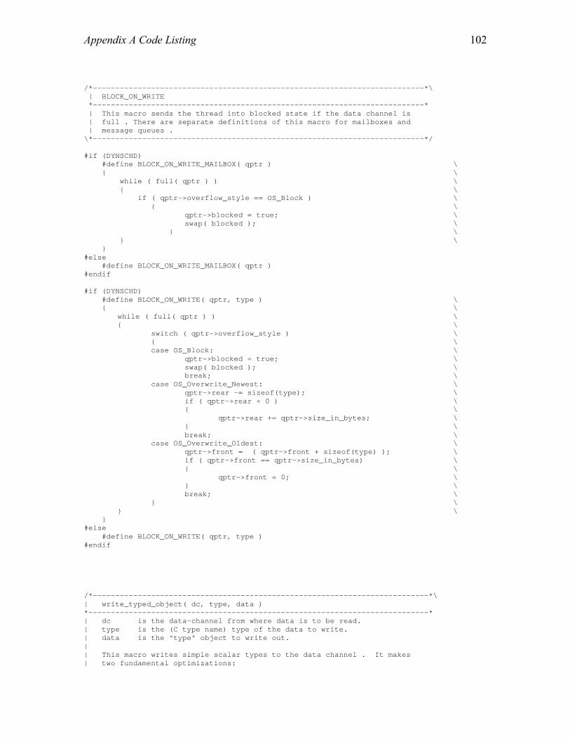
Appendix A Code Listing
102
/*--------------------------------------------------------------------------*\ | BLOCK_ON_WRITE *--------------------------------------------------------------------------* | This macro sends the thread into blocked state if the data channel is | full . There are separate definitions of this macro for mailboxes and | message queues . \*--------------------------------------------------------------------------*/ #if (DYNSCHD) #define BLOCK_ON_WRITE_MAILBOX( qptr ) \ { \ while ( full( qptr ) ) \ { \ if ( qptr->overflow_style == OS_Block ) \ { \ qptr->blocked = true; \ swap( blocked ); \ } \ } \ } #else #define BLOCK_ON_WRITE_MAILBOX( qptr ) #endif #if (DYNSCHD) #define BLOCK_ON_WRITE( qptr, type ) \ { \ while ( full( qptr ) ) \ { \ switch ( qptr->overflow_style ) \ { \ case OS_Block: \ qptr->blocked = true; \ swap( blocked ); \ break; \ case OS_Overwrite_Newest: \ qptr->rear -= sizeof(type); \ if ( qptr->rear < 0 ) \ { \ qptr->rear += qptr->size_in_bytes; \ } \ break; \ case OS_Overwrite_Oldest: \ qptr->front = ( qptr->front + sizeof(type) ); \ if ( qptr->front == qptr->size_in_bytes) \ { \ qptr->front = 0; \ } \ break; \ } \ } \ } #else #define BLOCK_ON_WRITE( qptr, type ) #endif /*---------------------------------------------------------------------------*\ | write_typed_object( dc, type, data ) *----------------------------------------------------------------------------* | dc is the data-channel from where data is to be read. | type is the (C type name) type of the data to write. | data is the "type" object to write out. | | This macro writes simple scalar types to the data channel . It makes | two fundamental optimizations:

Appendix A Code Listing
103
| 1) Because the data channel buffer is defined to hold an integral | number of "type" objects, all objects will always be stored | contiguously in the buffer (none will have to be split, with part | on the trailing edge of the buffer and the remainder on the leading | edge). | 2) Transferring a value of "type" can be done more cheaply with a | single assignment statement than with memcpy, because the objects | are so small. | | Also (not really fundamental, but may save an instruction or two): | 3) since the type is coming in as a macro parameter, we can use the | compile-time constant sizeof(type) instead of retrieving it from | the queue's element_size field. \*---------------------------------------------------------------------------*/ #if (USE_MAILBOX) #define write_typed_object( dc, type, data ) \ { \ QueuePointer qptr = (QueuePointer) dc; \ log("Writing to mailbox\n"); \ BLOCK_ON_WRITE_MAILBOX( qptr ) \ *(type*)( qptr->buffer ) = data; \ qptr->num_entries = 1; \ setmask_on_write( qptr ); \ \ /* Switch to OS to see if any higher priority process is ready or action is pending */ \ WRITE_GOTO_OS( qptr ) \ } #else #define write_typed_object( dc, type, data ) \ { \ QueuePointer qptr = (QueuePointer) dc; \ int local_front ; \ int local_rear ; \ log("Writing to data channel\n"); \ \ BLOCK_ON_WRITE( qptr, type ) \ \ local_front = qptr->front; \ local_rear = qptr->rear; \ \ *(type*)( qptr->buffer + local_rear ) = data; \ local_rear = ( local_rear + sizeof(type) ); \ if ( local_rear == qptr->size_in_bytes) \ { \ local_rear = 0; \ } \ qptr->num_entries++; \ \ qptr->front = local_front; \ qptr->rear = local_rear; \ \ setmask_on_write( qptr ); \ \ /* Switch to OS to see if any higher priority process is ready or action is\ pending */ \ WRITE_GOTO_OS( qptr ) \ } #endif /*------------------------------------------------------------------------*\ | API macro definitions *-------------------------------------------------------------------------*/ #define write_bool_DC( dc, data ) \ write_typed_object( dc, bool, data )

Appendix A Code Listing
104
#define write_char_DC( dc, data ) \ write_typed_object( dc, char, data ) #define write_int_DC( dc, data ) \ write_typed_object( dc, int, data ) #define write_float_DC( dc, data ) \ write_typed_object( dc, float, data ) #define write_double_DC( dc, data ) \ write_typed_object( dc, double, data ) #define write_pointer_DC( dc, data ) \ write_typed_object( dc, (void *), data ) #define write_bytes_DC( dc, data, length ) \ write_raw_bytes( dc, Type_Byte, data, length ) #define write_int_array_DC( dc, data, array_dim ) \ write_raw_bytes( dc, Type_Int_Array, (char *)data, \ ((QueuePointer)dc)->element_size ) #define write_float_array_DC( dc, data, array_dim ) \ write_raw_bytes( dc, Type_Float_Array, (char *)data, \ ((QueuePointer)dc)->element_size ) #define write_double_array_DC( dc, data, array_dim ) \ write_raw_bytes( dc, Type_Double_Array, (char *)data, \ ((QueuePointer)dc)->element_size ) # endif

Appendix A Code Listing
105
/*==========================================================================*\ | 060_hdr.asm *--------------------------------------------------------------------------* | This file implements the interrupt handler for external interrupts in | Analog Devices SHARC assembly . \*==========================================================================*/ #define __ADSP21060__ 1 #undef __ADSP21020__ #include "sig_glob.h" #define INT(irp) \ BIT CLR MODE1 0x1000; / * Disable interrupts */ \ JUMP ___z3_int_determiner(DB); /* jmp to finish setting up */ \ DM(I7,M7)=I15; /* Save I15 (scratch reg) */ \ I15=SIGMASK(SIG_##irp); /* Base of int table */ #define MAX_LENGTH_EVENT_Q 16 #define RESERVED_INTERRUPT NOP;NOP;NOP;NOP /* Variables to store the registers used for storing the event code */ .segment/dm seg_dmda; .var astat_store; .var i5_store; .var m4_store; .var r5_store; .var r6_store; .var r7_store; .endseg; .GLOBAL ___lib_prog_term; /*Termination address */ .GLOBAL __done_execution; .EXTERN ___lib_setup_c; .SEGMENT/PM seg_rth; /*Runtime header segment */ RESERVED_INTERRUPT; ___lib_RSTI: NOP; /* Not really executed */ JUMP ___lib_start; NOP; NOP; RESERVED_INTERRUPT; ___lib_SOVFI: INT(SOVF); /* status/loop/PC stack overflow */ ___lib_TMZHI: INT(TMZ0); /* high priority timer */ ___lib_VIRPTI: INT(VIRPTI); /* external interrupts */ ___lib_IRQ2I: INT(IRQ2); ___lib_IRQ1I: INT(IRQ1); /*------------------------------------------------------------------------*\ | ISR for external interrupts. It just adds an event code to an event | queue. The kernel is responsible to service that event. *-------------------------------------------------------------------------*/ ___lib_IRQ0I: BIT CLR MODE1 0x1000; /* Disable interrupts */ JUMP (pc,3) (DB); /* jmp to finish setting up */ !DM(I7,M7)=I15; /* Save I15 (scratch reg) */ BIT SET MODE2 0x80000; /* freeze cache */ /* Saving the necessary registers */ dm(r5_store)=r5; dm(r6_store)=r6; dm(r7_store)=r7; dm(astat_store)=ASTAT; dm(i5_store)=i5;
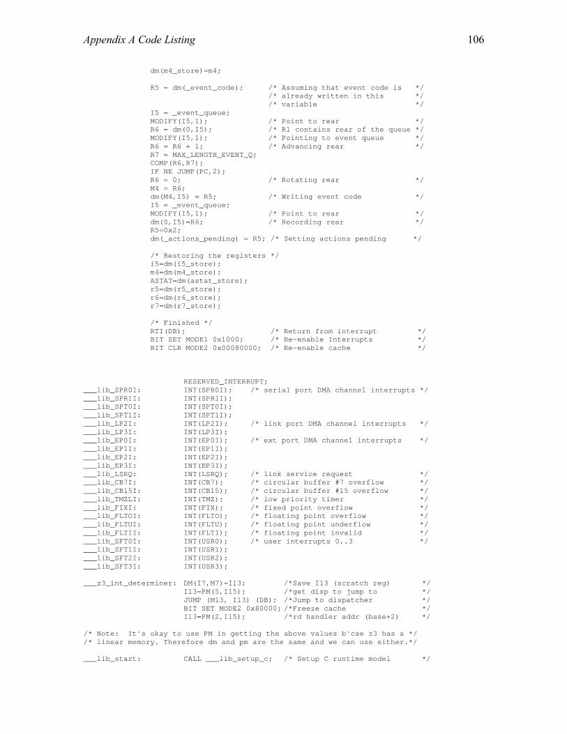
Appendix A Code Listing
106
dm(m4_store)=m4; R5 = dm(_event_code); /* Assuming that event code is */ /* already written in this */ /* variable */ I5 = _event_queue; MODIFY(I5,1); /* Point to rear */ R6 = dm(0,I5); /* R1 contains rear of the queue */ MODIFY(I5,1); /* Pointing to event queue */ R6 = R6 + 1; /* Advancing rear */ R7 = MAX_LENGTH_EVENT_Q; COMP(R6,R7); IF NE JUMP(PC,2); R6 = 0; /* Rotating rear */ M4 = R6; dm(M4,I5) = R5; /* Writing event code */ I5 = _event_queue; MODIFY(I5,1); /* Point to rear */ dm(0,I5)=R6; /* Recording rear */ R5=0x2; dm(_actions_pending) = R5; /* Setting actions pending */ /* Restoring the registers */ i5=dm(i5_store); m4=dm(m4_store); ASTAT=dm(astat_store); r5=dm(r5_store); r6=dm(r6_store); r7=dm(r7_store); /* Finished */ RTI(DB); /* Return from interrupt */ BIT SET MODE1 0x1000; /* Re-enable Interrupts */ BIT CLR MODE2 0x00080000; /* Re-enable cache */ RESERVED_INTERRUPT; ___lib_SPR0I: INT(SPR0I); /* serial port DMA channel interrupts */ ___lib_SPR1I: INT(SPR1I); ___lib_SPT0I: INT(SPT0I); ___lib_SPT1I: INT(SPT1I); ___lib_LP2I: INT(LP2I); /* link port DMA channel interrupts */ ___lib_LP3I: INT(LP3I); ___lib_EP0I: INT(EP0I); /* ext port DMA channel interrupts */ ___lib_EP1I: INT(EP1I); ___lib_EP2I: INT(EP2I); ___lib_EP3I: INT(EP3I); ___lib_LSRQ: INT(LSRQ); /* link service request */ ___lib_CB7I: INT(CB7); /* circular buffer #7 overflow */ ___lib_CB15I: INT(CB15); /* circular buffer #15 overflow */ ___lib_TMZLI: INT(TMZ); /* low priority timer */ ___lib_FIXI: INT(FIX); /* fixed point overflow */ ___lib_FLTOI: INT(FLTO); /* floating point overflow */ ___lib_FLTUI: INT(FLTU); /* floating point underflow */ ___lib_FLTII: INT(FLTI); /* floating point invalid */ ___lib_SFT0I: INT(USR0); /* user interrupts 0..3 */ ___lib_SFT1I: INT(USR1); ___lib_SFT2I: INT(USR2); ___lib_SFT3I: INT(USR3); ___z3_int_determiner: DM(I7,M7)=I13; /*Save I13 (scratch reg) */ I13=PM(5,I15); /*get disp to jump to */ JUMP (M13, I13) (DB); /*Jump to dispatcher */ BIT SET MODE2 0x80000; /*Freeze cache */ I13=PM(2,I15); /*rd handler addr (base+2) */ /* Note: It's okay to use PM in getting the above values b'cse z3 has a */ /* linear memory. Therefore dm and pm are the same and we can use either.*/ ___lib_start: CALL ___lib_setup_c; /* Setup C runtime model */

Appendix A Code Listing
107
#ifdef MAIN_RTS CJUMP _main (DB); /* Begin C program */ DM(I7,M7)=R2; DM(I7,M7)=PC; #else JUMP _main; /* Begin C program */ #endif /* Setting the __done_execution flag indicates that this processor is */ /* finished executing, for the benefit of anyone who may be watching. */ ___lib_prog_term: PM(__done_execution)=PC; IDLE; JUMP ___lib_prog_term; /* Stay put */ .VAR __done_execution = 0; .ENDSEG;

Appendix A Code Listing
108
/*==========================================================================*\ | setjmp_all.asm *--------------------------------------------------------------------------* | This file implements the module that saves ALL the thread context. \*==========================================================================*/ #include <asm_sprt.h> #define dm_1 M6 #define dm_ptr I4 #define frame_ptr I6 #define stack_ptr I7 #define FETCH_RETURN I12=DM(M7, frame_ptr); #define RETURN JUMP (M14,I12) #define frame_stk DM(0,I6) #define RESTORE_STACK stack_ptr=frame_ptr; #define RESTORE_FRAME frame_ptr=frame_stk; /*--------------------------------------------------------------------------*\ | Assembly language routine to save ALL the registers in the process context | structure \*--------------------------------------------------------------------------*/ .segment/pm seg_pmco; .global _setjmp_all; _setjmp_all: dm_ptr=R4; /* Point to Context structure */ DM(dm_ptr,dm_1)=MODE1; /* Save MODE1 */ DM(dm_ptr,dm_1)=R1; /* Saving 12 data registers */ DM(dm_ptr,dm_1)=R2; DM(dm_ptr,dm_1)=R3; DM(dm_ptr,dm_1)=R5; DM(dm_ptr,dm_1)=R6; DM(dm_ptr,dm_1)=R7; DM(dm_ptr,dm_1)=R9; DM(dm_ptr,dm_1)=R10; DM(dm_ptr,dm_1)=R11; DM(dm_ptr,dm_1)=R13; DM(dm_ptr,dm_1)=R14; DM(dm_ptr,dm_1)=R15; R12=B0; /* Saving DAG registers */ DM(dm_ptr,dm_1)=R12; R12=I0; DM(dm_ptr,dm_1)=R12; R12=M0; DM(dm_ptr,dm_1)=R12; R12=L0; DM(dm_ptr,dm_1)=R12; R12=B1; DM(dm_ptr,dm_1)=R12; R12=I1; DM(dm_ptr,dm_1)=R12; R12=M1; DM(dm_ptr,dm_1)=R12; R12=L1; DM(dm_ptr,dm_1)=R12; R12=B2; DM(dm_ptr,dm_1)=R12; R12=I2; DM(dm_ptr,dm_1)=R12; R12=M2; DM(dm_ptr,dm_1)=R12; R12=L2; DM(dm_ptr,dm_1)=R12;

Appendix A Code Listing
109
R12=B3; DM(dm_ptr,dm_1)=R12; R12=I3; DM(dm_ptr,dm_1)=R12; R12=M3; DM(dm_ptr,dm_1)=R12; R12=L3; DM(dm_ptr,dm_1)=R12; R12=B5; DM(dm_ptr,dm_1)=R12; R12=I5; DM(dm_ptr,dm_1)=R12; R12=L5; DM(dm_ptr,dm_1)=R12; R12=B6; DM(dm_ptr,dm_1)=R12; R12=I6; DM(dm_ptr,dm_1)=R12; R12=L6; DM(dm_ptr,dm_1)=R12; R12=B7; DM(dm_ptr,dm_1)=R12; R12=I7; DM(dm_ptr,dm_1)=R12; R12=L7; DM(dm_ptr,dm_1)=R12; /* Now save hardware specific state */ DM(dm_ptr,dm_1)=PCSTKP; /* Save current HW SP */ NOP; /* One cycle latency */ DM(dm_ptr,dm_1)=LADDR; /* Save Loop stack depth */ R0=R0-R0, FETCH_RETURN /* Return 0 for setjmp */ DM(dm_ptr,dm_1)=I12; /* Save return address */ restore_state: RETURN (DB); /* Back to caller */ RESTORE_STACK RESTORE_FRAME .ENDSEG;

Appendix A Code Listing
110
/*==========================================================================*\ | longjmp_all.asm *--------------------------------------------------------------------------* | This file implements the module that restores ALL the thread context. \*==========================================================================*/ #include <asm_sprt.h> #define dm_1 M6 #define dm_ptr I4 #define frame_ptr I6 #define RETURN JUMP (M14,I12) #define stack_ptr I7 #define RESTORE_STACK stack_ptr=frame_ptr; .segment/dm seg_dmda; .var return_value; .var jmp_buf_ptr; .endseg; /*--------------------------------------------------------------------------*\ | Assembly language routine to restore ALL the registers from the process | context structure \*--------------------------------------------------------------------------*/ .segment/pm seg_pmco; .global _longjmp_all; _longjmp_all: DM(return_value)=R8; DM(jmp_buf_ptr)=R4; dm_ptr=R4; MODE1=DM(dm_ptr,dm_1); NOP; dm_ptr=DM(jmp_buf_ptr); MODIFY(dm_ptr,1); R0=DM(return_value); IF EQ R0=R0+1; /* Must never return 0 */ R1=DM(dm_ptr,dm_1); /* Begin restoring data regs */ R2=DM(dm_ptr,dm_1); R3=DM(dm_ptr,dm_1); R5=DM(dm_ptr,dm_1); R6=DM(dm_ptr,dm_1); R7=DM(dm_ptr,dm_1); R9=DM(dm_ptr,dm_1); R10=DM(dm_ptr,dm_1); R11=DM(dm_ptr,dm_1); R13=DM(dm_ptr,dm_1); R14=DM(dm_ptr,dm_1); R15=DM(dm_ptr,dm_1); /* We can read directly into DAG1 as long as we use preindexed, */ /* not postindexed addressing */ B0=DM(0,dm_ptr); I0=DM(1,dm_ptr); M0=DM(2,dm_ptr); L0=DM(3,dm_ptr); B1=DM(4,dm_ptr); I1=DM(5,dm_ptr); M1=DM(6,dm_ptr); L1=DM(7,dm_ptr); B2=DM(8,dm_ptr); I2=DM(9,dm_ptr);
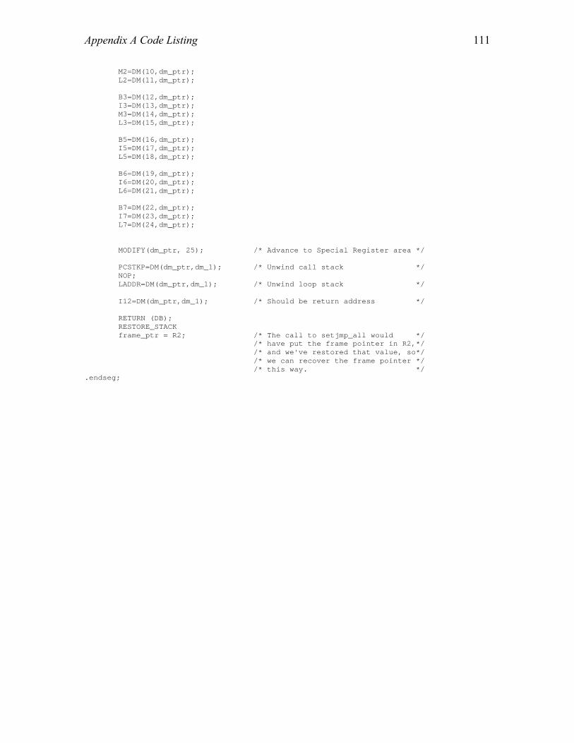
Appendix A Code Listing
111
M2=DM(10,dm_ptr); L2=DM(11,dm_ptr); B3=DM(12,dm_ptr); I3=DM(13,dm_ptr); M3=DM(14,dm_ptr); L3=DM(15,dm_ptr); B5=DM(16,dm_ptr); I5=DM(17,dm_ptr); L5=DM(18,dm_ptr); B6=DM(19,dm_ptr); I6=DM(20,dm_ptr); L6=DM(21,dm_ptr); B7=DM(22,dm_ptr); I7=DM(23,dm_ptr); L7=DM(24,dm_ptr); MODIFY(dm_ptr, 25); /* Advance to Special Register area */ PCSTKP=DM(dm_ptr,dm_1); /* Unwind call stack */ NOP; LADDR=DM(dm_ptr,dm_1); /* Unwind loop stack */ I12=DM(dm_ptr,dm_1); /* Should be return address */ RETURN (DB); RESTORE_STACK frame_ptr = R2; /* The call to setjmp_all would */ /* have put the frame pointer in R2,*/ /* and we've restored that value, so*/ /* we can recover the frame pointer */ /* this way. */ .endseg;

Appendix A Code Listing
112
/*==========================================================================*\ | shallow_setjmp.asm *--------------------------------------------------------------------------* | This file implements the module that stores only selected registers . It | is used when context switching takes place between the primary and | alternate register sets . \*==========================================================================*/ #include <asm_sprt.h> #define dm_1 M6 #define dm_ptr I4 #define frame_ptr I6 #define stack_ptr I7 #define frame_stk DM(0,I6) #define RESTORE_STACK stack_ptr=frame_ptr; #define RESTORE_FRAME frame_ptr=frame_stk; #define RETURN JUMP (M14,I12) #define FETCH_RETURN I12=DM(M7, frame_ptr); .segment/pm seg_pmco; .global _shallow_setjmp; /*--------------------------------------------------------------------------*\ | Assembly language routine to store partial context while switching between | two register sets . \*--------------------------------------------------------------------------*/ _shallow_setjmp: dm_ptr=R4; /* Point to jmp_buf */ DM(dm_ptr,dm_1)=MODE1; /* Save MODE1 */ MODIFY(dm_ptr,37); DM(dm_ptr,dm_1)=PCSTKP; /* Save current HW SP */ NOP; /* One cycle latency */ DM(dm_ptr,dm_1)=LADDR; /* Save Loop stack depth */ R0=R0-R0, FETCH_RETURN /* Return 0 for setjmp */ DM(dm_ptr,dm_1)=I12; /* Save return address */ restore_state: RETURN (DB); /* Back to caller */ RESTORE_STACK RESTORE_FRAME .ENDSEG;
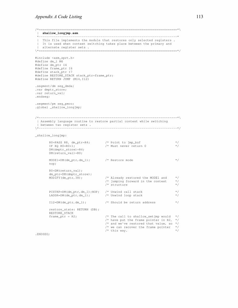
Appendix A Code Listing
113
/*==========================================================================*\ | shallow_longjmp.asm *--------------------------------------------------------------------------* | This file implements the module that restores only selected registers . | It is used when context switching takes place between the primary and | alternate register sets . \*==========================================================================*/ #include <asm_sprt.h> #define dm_1 M6 #define dm_ptr I4 #define frame_ptr I6 #define stack_ptr I7 #define RESTORE_STACK stack_ptr=frame_ptr; #define RETURN JUMP (M14,I12) .segment/dm seg_dmda; .var dmptr_store; .var return_val; .endseg; .segment/pm seg_pmco; .global _shallow_longjmp; /*--------------------------------------------------------------------------*\ | Assembly language routine to restore partial context while switching | between two register sets . \*--------------------------------------------------------------------------*/ _shallow_longjmp: R0=PASS R8, dm_ptr=R4; /* Point to jmp_buf */ IF EQ R0=R0+1; /* Must never return 0 */ DM(dmptr_store)=R4; DM(return_val)=R0; MODE1=DM(dm_ptr,dm_1); /* Restore mode */ nop; R0=DM(return_val); dm_ptr=DM(dmptr_store); MODIFY(dm_ptr,38); /* Already restored the MODE1 and */ /* jumping forward in the context */ /* structure */ PCSTKP=DM(dm_ptr,dm_1);NOP; /* Unwind call stack */ LADDR=DM(dm_ptr,dm_1); /* Unwind loop stack */ I12=DM(dm_ptr,dm_1); /* Should be return address */ restore_state: RETURN (DB); RESTORE_STACK frame_ptr = R2; /* The call to shallow_setjmp would */ /* have put the frame pointer in R2, */ /* and we've restored that value, so */ /* we can recover the frame pointer */ /* this way. */ .ENDSEG;

Appendix A Code Listing
114
/*==========================================================================*\ | convert_setjmp.asm *--------------------------------------------------------------------------* | This file implements the module that converts the context saved through | a shallow_setjmp routine to context saved through setjmp_all . This is | needed when the scheduler is executing in the primary register set and | a higher priority thread becomes ready because of an interrupt . In that | case, the partial context saved for the thread executing in the alternate | register set has to be converted to full context, so that the higher | priority thread can begin in the alternate register set . \*==========================================================================*/ #include <asm_sprt.h> #define dm_1 M6 #define dm_ptr I4 #define frame_ptr I6 #define stack_ptr I7 #define FETCH_RETURN I12=DM(M7, frame_ptr); #define RETURN JUMP (M14,I12) #define frame_stk DM(0,I6) #define RESTORE_STACK stack_ptr=frame_ptr; #define RESTORE_FRAME frame_ptr=frame_stk; .segment/dm seg_dmda; .var dmptr_store; .endseg; /*--------------------------------------------------------------------------*\ | Assembly language routine to convert shallow_setjmp to setjmp_all . \*--------------------------------------------------------------------------*/ .segment/pm seg_pmco; .global _convert_shallow_setjmp_to_all; _convert_shallow_setjmp_to_all: push sts; /* Save ASTAT and MODE1 registers */ DM(dmptr_store)=R4; /* Point to Context structure */ dm_ptr=R4; MODE1=DM(dm_ptr,dm_1); /* Restore alternate register mode */ nop; dm_ptr = DM(dmptr_store); MODIFY(dm_ptr,1); /* MODE1 already saved */ DM(dm_ptr,dm_1)=R1; /* Saving 12 data registers */ DM(dm_ptr,dm_1)=R2; DM(dm_ptr,dm_1)=R3; DM(dm_ptr,dm_1)=R5; DM(dm_ptr,dm_1)=R6; DM(dm_ptr,dm_1)=R7; DM(dm_ptr,dm_1)=R9; DM(dm_ptr,dm_1)=R10; DM(dm_ptr,dm_1)=R11; DM(dm_ptr,dm_1)=R13; DM(dm_ptr,dm_1)=R14; DM(dm_ptr,dm_1)=R15; /* Now save DAG1 */ R12=B0; DM(dm_ptr,dm_1)=R12; R12=I0; DM(dm_ptr,dm_1)=R12; R12=M0; DM(dm_ptr,dm_1)=R12; R12=L0; DM(dm_ptr,dm_1)=R12;

Appendix A Code Listing
115
R12=B1; DM(dm_ptr,dm_1)=R12; R12=I1; DM(dm_ptr,dm_1)=R12; R12=M1; DM(dm_ptr,dm_1)=R12; R12=L1; DM(dm_ptr,dm_1)=R12; R12=B2; DM(dm_ptr,dm_1)=R12; R12=I2; DM(dm_ptr,dm_1)=R12; R12=M2; DM(dm_ptr,dm_1)=R12; R12=L2; DM(dm_ptr,dm_1)=R12; R12=B3; DM(dm_ptr,dm_1)=R12; R12=I3; DM(dm_ptr,dm_1)=R12; R12=M3; DM(dm_ptr,dm_1)=R12; R12=L3; DM(dm_ptr,dm_1)=R12; R12=B5; DM(dm_ptr,dm_1)=R12; R12=I5; DM(dm_ptr,dm_1)=R12; R12=L5; DM(dm_ptr,dm_1)=R12; R12=B6; DM(dm_ptr,dm_1)=R12; R12=I6; DM(dm_ptr,dm_1)=R12; R12=L6; DM(dm_ptr,dm_1)=R12; R12=B7; DM(dm_ptr,dm_1)=R12; R12=I7; DM(dm_ptr,dm_1)=R12; R12=L7; DM(dm_ptr,dm_1)=R12; pop sts; nop; FETCH_RETURN RETURN (DB); /* Back to caller */ RESTORE_STACK RESTORE_FRAME .ENDSEG;

Appendix A Code Listing
116
/*===========================================================================*\ | OS_startup.c *----------------------------------------------------------------------------* | This module allocates and initializes the data channels and Process | Control Blocks during the OS startup phase. It uses the definition of DFG | Nodes and DFG Edges given in the DFG.h file and initializes the OS | structures on the basis of those definitions. | \*===========================================================================*/ #include "ECO.h" #include "checks.h" #include <stdio.h> int NUM_DFG_NODES; /* Number of DFG Nodes */ int NUM_DFG_EDGES; /* Number of DFG Edges */ Data_Channel *OS_All_DC; /* Pointer to Array containing pointers to */ /* all the DCs */ OS_Process *OS_All_Process; /* Pointers to all the processes */ void initialize_DC_process_handles(void); /*---------------------------------------------------------------------------*\ | allocate_initialize_DC *----------------------------------------------------------------------------* | Function which allocates space to the Data Channels and initializes them. \*---------------------------------------------------------------------------*/ void allocate_initialize_DC(void) { int total_space = 0; /* Total space needed for the data channels */ int header_space; /* Space needed by the Data Channel Header */ int i; /* Used as an index */ int **buffer_DC; /* Stores the element size and size of each */ /* channel */ int buffer_index = 0; /* Index for the buffer_DC array */ char *space_ptr; /* Pointer pointing to the memory pool */ DC_Queue *DC_ptr; /* Pointer to the data channel header */ int *temp,*ptr_b_dc; int dc_size; /* Temporary variable to hold data channel */ /* size */ /*---------------------------------------------------------------------------*\ | Calculating the number of Nodes and Edges \*---------------------------------------------------------------------------*/ i = 0; while (!NODE_TERMINATED(DFG_Node_Set[i])) { i++; } NUM_DFG_NODES = i; i = 0; while (!EDGE_TERMINATED(DFG_Edge_Set[i])) { i++; } NUM_DFG_EDGES = i; /* Allocating space to the buffer_dc two dimensional array */ ptr_b_dc = (int *)malloc(2*NUM_DFG_EDGES*sizeof(int) + NUM_DFG_EDGES*sizeof(int *)); buffer_DC = (int **)ptr_b_dc; temp = ptr_b_dc + NUM_DFG_EDGES*sizeof(int *); for (i=0;i<NUM_DFG_EDGES;i++) { buffer_DC[i] = temp; temp = temp + 2*sizeof(int); }

Appendix A Code Listing
117
/*---------------------------------------------------------------------------*\ | Calculating the space needed for all the data channels \*---------------------------------------------------------------------------*/ for (i=0; i<NUM_DFG_EDGES; i++) { /* Over-riding the size given by the user, if mailbox option is enabled */ #if (USE_MAILBOX) dc_size = 1; #else dc_size = DFG_Edge_Set[i].size; #endif if (DFG_Edge_Set[i].array_dimensions == NULL) /* Data Channel contains simple */ /* data type */ { switch (DFG_Edge_Set[i].type) { case Type_Int: buffer_DC[buffer_index][0] = sizeof(int); buffer_DC[buffer_index][1] = dc_size * buffer_DC[buffer_index][0]; buffer_index++; break; case Type_Float: buffer_DC[buffer_index][0] = sizeof(float); buffer_DC[buffer_index][1] = dc_size * buffer_DC[buffer_index][0]; buffer_index++; break; case Type_Double: buffer_DC[buffer_index][0] = sizeof(double); buffer_DC[buffer_index][1] = dc_size * buffer_DC[buffer_index][0]; buffer_index++; break; case Type_Char: buffer_DC[buffer_index][0] = sizeof(char); buffer_DC[buffer_index][1] = dc_size * buffer_DC[buffer_index][0]; buffer_index++; break; case Type_Bool: buffer_DC[buffer_index][0] = sizeof(bool); buffer_DC[buffer_index][1] = dc_size * buffer_DC[buffer_index][0]; buffer_index++; break; case Type_String: buffer_DC[buffer_index][0] = sizeof(char); buffer_DC[buffer_index][1] = dc_size * buffer_DC[buffer_index][0]; buffer_index++; break; case Type_Pointer: buffer_DC[buffer_index][0] = sizeof(void*); buffer_DC[buffer_index][1] = dc_size * buffer_DC[buffer_index][0]; buffer_index++; break; case Type_Byte: buffer_DC[buffer_index][0] = 1; buffer_DC[buffer_index][1] = dc_size; buffer_index++; break; } /* switch */ } /* if */ else /* Data Channel has array data type */ { /* Calculating the number of elements in the array */ unsigned int j=0; unsigned int num_elements = 1; while (DFG_Edge_Set[i].array_dimensions[j] != 0) { num_elements *= DFG_Edge_Set[i].array_dimensions[j]; j++; } /* Calculating the space needed based on type */

Appendix A Code Listing
118
switch (DFG_Edge_Set[i].type) { case Type_Int_Array: buffer_DC[buffer_index][0] = sizeof(int) * num_elements; buffer_DC[buffer_index][1] = dc_size * buffer_DC[buffer_index][0]; buffer_index++; break; case Type_Float_Array: buffer_DC[buffer_index][0] = sizeof(float) * num_elements; buffer_DC[buffer_index][1] = dc_size * buffer_DC[buffer_index][0]; buffer_index++; break; case Type_Double_Array: buffer_DC[buffer_index][0] = sizeof(double) * num_elements; buffer_DC[buffer_index][1] = dc_size * buffer_DC[buffer_index][0]; buffer_index++; break; } } /* else */ } /* for */ /* Calculating the total space needed by the elements */ for (buffer_index = 0; buffer_index < NUM_DFG_EDGES; buffer_index++) { total_space += buffer_DC[buffer_index][1]; } /* Space required by the header structure */ header_space = sizeof(DC_Queue); /* Adding the size of the Data Channel header structure and allocating space */ total_space += NUM_DFG_EDGES * header_space; space_ptr = (char *)malloc(total_space + NUM_DFG_EDGES*sizeof(Data_Channel) + NUM_DFG_NODES*sizeof(OS_Process)); OS_All_DC = (Data_Channel *)(space_ptr + total_space); OS_All_Process = (OS_Process *)(OS_All_DC + NUM_DFG_EDGES*sizeof(Data_Channel)); /* Now chopping off the space and allocating it to data channels */ for (i=0; i<NUM_DFG_EDGES; i++) { OS_All_DC[i] = space_ptr; space_ptr += header_space + buffer_DC[i][1]; } /* Initializing the data channel headers */ for (i=0; i<NUM_DFG_EDGES; i++) { DC_ptr = (DC_Queue *)OS_All_DC[i]; DC_ptr->type = DFG_Edge_Set[i].type; DC_ptr->element_size = buffer_DC[i][0]; DC_ptr->array_dimensions = DFG_Edge_Set[i].array_dimensions; DC_ptr->overflow_style = DFG_Edge_Set[i].overflow_style; DC_ptr->interrupt_driven = DFG_Edge_Set[i].interrupt_driven; DC_ptr->front = 0; DC_ptr->rear = 0; /* This leaves one byte unused, but makes the other size */ /* computations a bit more understandable */ DC_ptr->size_in_bytes = buffer_DC[i][1]; #if (USE_MAILBOX) DC_ptr->size_in_elts = 1; #else DC_ptr->size_in_elts = DFG_Edge_Set[i].size; #endif DC_ptr->num_entries = 0; DC_ptr->index = i; } free(ptr_b_dc); /* Free space allocated to the buffer DC two dim array */

Appendix A Code Listing
119
} /* Function allocate_initialize_DC*/ /*---------------------------------------------------------------------------*\ | allocate_initialize_process *----------------------------------------------------------------------------* | Function which allocates space to the Process Control Blocks and | initializes them. \*---------------------------------------------------------------------------*/ void allocate_initialize_process(void) { char *space_ptr; /* Points to the free space */ Data_Channel *input_port_handles; /* Stores the indices of input DCs to a */ /* node */ Data_Channel *output_port_handles; /* Stores the indices of output DCs from */ /* a node */ volatile int index,i; /* Indices for the DFG Node and Edges */ /* respectively */ volatile short int inp_p_num; /* Number of input port and output ports */ volatile short int out_p_num; /* of a node */ char *port_handles; /* Points to the space allocated for port*/ /* handles */ int process_size = sizeof(Process); /* Size of the Process Control Block */ short int Data_Channels_size = sizeof(Data_Channels); Process *pcb; /* Pointer to a Process Control Block */ DC_Queue *DC_ptr; unsigned int total_stack_size = 0; #if (MTHREADED) unsigned int *stack_space_ptr; /* Points to the space allocated for */ /* process stacks */ #endif OS_All_Process = (OS_Process *)malloc(NUM_DFG_NODES*sizeof(OS_Process)); input_port_handles = (Data_Channel *)malloc( 2*NUM_DFG_EDGES*sizeof(Data_Channel) ); if (input_port_handles == NULL) { log("Not enough space\n"); } output_port_handles = input_port_handles + NUM_DFG_EDGES*sizeof(Data_Channel); /*---------------------------------------------------------------------------*\ Calculating the stack space necessary for all the processes \*---------------------------------------------------------------------------*/ #if (MTHREADED) for (index=0; index<NUM_DFG_NODES; index++) { if (DFG_Node_Set[index].eco == 0) { continue; } total_stack_size += (DFG_Node_Set[index].eco)->stack_size; } #else total_stack_size = 0; /* For a single threaded system */ #endif /*---------------------------------------------------------------------------*\ Allocating space for the process control blocks. The first term accounts for the space required by the Process structure. The second term accounts for the space required to store the input and output port handles. One DFG edge is responsible for one input handle and one output handle. The third term accounts for the stack space needed by all the processes. Allocation done in the following format : _______________________________________________________________ | Processes | Port Handles | Process Stacks | --------------------------------------------------------------- \*---------------------------------------------------------------------------*/

Appendix A Code Listing
120
space_ptr = (char *)malloc( (NUM_DFG_NODES * process_size) + (2 * NUM_DFG_EDGES * sizeof(Data_Channel)) + total_stack_size*sizeof(unsigned int)); if (space_ptr == NULL) { log("Not enough space for process control block allocation\n"); ) port_handles = space_ptr + (NUM_DFG_NODES * process_size); #if (MTHREADED) stack_space_ptr = (unsigned int *)(port_handles + (2 * NUM_DFG_EDGES * sizeof(Data_Channel))); #endif for (index=0; index<NUM_DFG_NODES; index++) { if (DFG_Node_Set[index].eco == 0) { OS_All_Process[index] = NULL; continue; } OS_All_Process[index] = pcb = (Process *)space_ptr; inp_p_num = out_p_num = 0; /* Initializing the indices */ pcb->eco = DFG_Node_Set[index].eco; pcb->process_state = wait_for_fire; /* Process Just Born ! */ #if (DYNSCHD) pcb->firing_rule = DFG_Node_Set[index].firing_rules[DFG_Node_Set[index].firing_rule_name]; pcb->in_ports_ready = 0; /* Initialize */ #endif #if (MTHREADED) pcb->stack_pointer = stack_space_ptr; /* Initialize the stack for the */ /* process */ stack_space_ptr = stack_space_ptr + (DFG_Node_Set[index].eco)->stack_size; pcb->stack_size = (DFG_Node_Set[index].eco)->stack_size; #endif (pcb->p).config = DFG_Node_Set[index].configuration; (pcb->p).current_priority = DFG_Node_Set[index].initial_priority; (pcb->p).wakeup_call = DFG_Node_Set[index].default_mask; /* Initialize */ space_ptr = space_ptr + process_size; /* Searching for the input and output port handles */ for (i=0; i<NUM_DFG_EDGES; i++) { if (DFG_Edge_Set[i].source == index)/* Found an output port */ { output_port_handles[DFG_Edge_Set[i].source_out_port] = OS_All_DC[i]; out_p_num++; } if (DFG_Edge_Set[i].sink == index) /* Found an input port */ { input_port_handles[DFG_Edge_Set[i].sink_in_port] = OS_All_DC[i]; inp_p_num++; } } /* Configuring the input/output port handles in the process control block */ if (out_p_num == 0) { (pcb->p).out_port = NULL; } else { Data_Channels temp_handle = (Data_Channels)port_handles; (pcb->p).out_port = (Data_Channels)port_handles; for (i=0; i<out_p_num; i++) {

Appendix A Code Listing
121
*temp_handle = output_port_handles[i]; temp_handle++; port_handles += Data_Channels_size; } } if (inp_p_num == 0) { (pcb->p).in_port = NULL; } else { Data_Channels temp_handle = (Data_Channels)port_handles; (pcb->p).in_port = (Data_Channels)port_handles; for (i=0; i<inp_p_num; i++) { *temp_handle = input_port_handles[i]; temp_handle++; port_handles += Data_Channels_size; } } /* else */ } /* for */ /* Initialize the process handles in each data channel */ for (i=0; i<NUM_DFG_EDGES; i++) { DC_ptr = (DC_Queue *)OS_All_DC[i]; DC_ptr->source_process = OS_All_Process[DFG_Edge_Set[i].source]; DC_ptr->sink_process = OS_All_Process[DFG_Edge_Set[i].sink]; } } /* function allocate_initialize_process */

Appendix A Code Listing
122
/*============================================================================*\ | dstructutil.c *-----------------------------------------------------------------------------* | This file contains the functions to maintain the data structures used in | the OS. It also has the common functions, etc. \*============================================================================*/ #include "ECO.h" #include <stdio.h> #include <string.h> #define COMPARE(x,y) (( (x) < (y) ) ? -1: ((x) == (y)) ? 0: 1) /* Macro for comparison */ extern Data_Channel *OS_All_DC; /* Array containing pointers to all the DCs */ extern OS_Process *OS_All_Process; /* Array containing pointers to all the */ /* processes */ extern int NUM_DFG_NODES; /* Number of DFG Nodes */ extern int NUM_DFG_EDGES; /* Number of DFG Edges */ extern volatile int ready_queue_size; /* the ready heap size */ extern Process *current_process; extern volatile int current_time; /* Holds the current timer value given by ISR*/ extern volatile Action_State actions_pending; /* To handle the time arrows and events */ extern Process **ready_queue; extern Timed_Wait_Queue waiting_queue;/* Waiting queue for timed waits */ extern Event_Queue event_queue; /* Event queue (for interrupts) */ #if (MTHREADED) extern Context OS_env; /* Context saving space for the OS */ #endif /*----------------------------------------------------------------------------*\ | swap *-----------------------------------------------------------------------------* | Function to swap the current running process with the process on the head | of the ready queue . \*----------------------------------------------------------------------------*/ void swap(Process_State next_state) { current_process->process_state = next_state; #if (MTHREADED) if (next_state == dead) { shallow_longjmp(&OS_env,1); } if (setjmp_all(&(current_process->process_env)) == 0) { shallow_longjmp(&OS_env,1); } #endif return; } /*----------------------------------------------------------------------------*\ | insert_ready_queue *-----------------------------------------------------------------------------* | Function to insert a thread control block into the ready queue, which is | implemented as a max-heap . \*----------------------------------------------------------------------------*/ void insert_ready_queue( Process *process, volatile int *n ) { int i, new_i; Process **heap = (Process **)ready_queue;

Appendix A Code Listing
123
i = ++(*n); new_i = i >> 1; while ( i!=1 && process->p.current_priority > heap[new_i]->p.current_priority ) { heap[i] = heap[new_i]; i = new_i; new_i >>= 1; } heap[i] = process; } /*----------------------------------------------------------------------------*\ | delete_ready_queue *-----------------------------------------------------------------------------* | Function to delete a thread control block from the ready queue, which is | implemented as a max-heap . \*----------------------------------------------------------------------------*/ Process *delete_ready_queue( volatile int *q_size ) { int parent; int child; int *n = (int *)q_size; Process* item; Process* temp; Process** heap = (Process **)ready_queue; /* Taking special actions if the heap size is 1, 2 or 3 */ switch(*n) { case 1 : (*n)--; return heap[1]; case 2 : item = heap[1]; heap[--(*n)] = heap[2]; return item; case 3 : (*n)--; item = heap[1]; if ( heap[3]->p.current_priority > heap[2]->p.current_priority ) { heap[1] = heap[3]; } else { heap[1] = heap[2]; heap[2] = heap[3]; } return item; } item = heap[1]; if ((*n) > 0 ) { temp = heap[(*n)--]; parent = 1; child = 2; while ( child <= *n ) { if ( child < *n && heap[child]->p.current_priority < heap[child + 1]->p.current_priority ) { child++; } if ( temp->p.current_priority >= heap[child]->p.current_priority ) { break;

Appendix A Code Listing
124
} heap[parent] = heap[child]; parent = child; child <<= 1; /* child*2 */ } heap[parent] = temp; } return item; } /*----------------------------------------------------------------------------*\ | change_ready_queue *-----------------------------------------------------------------------------* | This function changes the priority of a process at position "pos" in the | heap to a new value "newval". \*----------------------------------------------------------------------------*/ void change_ready_queue(Process *process_to_change,int newval,int *n) { int parent,child,pos=1; Process *temp; Process **heap = (Process **)ready_queue; /* Finding the position of the process in the heap */ while (pos<=*n) { if (process_to_change == heap[pos]) { break; } else { pos++; } } temp = heap[(*n)--]; parent = pos; child = 2*pos; while (child <= *n) { if ( (child < *n) && ( (heap[child]->p).current_priority < (heap[child+1]-> p).current_priority ) ) { child++; } if ( (temp->p).current_priority >= (heap[child]->p).current_priority ) { break; } heap[parent] = heap[child]; parent = child; child *= 2; } heap[parent] = temp; (process_to_change->p).current_priority = newval; insert_ready_queue(process_to_change, n); } /*==========================================================================*\ | Waiting Queue Operations *--------------------------------------------------------------------------* | Processes which are delayed are put into the waiting queue \*==========================================================================*/

Appendix A Code Listing
125
/*----------------------------------------------------------------------------*\ | insert_waiting_queue *-----------------------------------------------------------------------------* | Function to insert a Thread Control Block into a waiting queue. The elements | of this queue are arranged in ascending order of waking times. \*----------------------------------------------------------------------------*/ void insert_waiting_queue(Process *p) { short int position = (waiting_queue.front + 1) % MAX_LENGTH_WAITING_Q; /* if the queue is empty */ if (waiting_queue.front == waiting_queue.rear) { waiting_queue.rear = (waiting_queue.rear + 1) % MAX_LENGTH_WAITING_Q; if (waiting_queue.front == waiting_queue.rear) { swap(blocked);//Queue full } waiting_queue.queue[waiting_queue.rear] = p; return; } /* Finding the position where to insert if the queue is not */ /* empty (earliest wakeup time) */ while( waiting_queue.queue[position]->wakeup_time <= p->wakeup_time && position != waiting_queue.rear ) { position = (position + 1) % MAX_LENGTH_WAITING_Q; } /* If it is the last element */ if ( position == waiting_queue.rear ) { /* the last element is smaller or equal ::: no need to shift */ if ( waiting_queue.queue[position]->wakeup_time <= p->wakeup_time ) { waiting_queue.rear = (waiting_queue.rear + 1) % MAX_LENGTH_WAITING_Q; if (waiting_queue.front == waiting_queue.rear) { swap(blocked);//Queue full } waiting_queue.queue[waiting_queue.rear] = p; return; } /* the last element is larger ::: shift */ else { waiting_queue.rear = (waiting_queue.rear + 1) % MAX_LENGTH_WAITING_Q; if (waiting_queue.front == waiting_queue.rear) { swap(blocked);//Queue full } waiting_queue.queue[waiting_queue.rear] = waiting_queue.queue[position]; waiting_queue.queue[position] = p; return; } } else /* element in between (Got the "position" where to insert) */ { short int temp_rear,temp_rear_previous = waiting_queue.rear; waiting_queue.rear = (waiting_queue.rear + 1) % MAX_LENGTH_WAITING_Q; if (waiting_queue.front == waiting_queue.rear) { swap(blocked);//Queue full } temp_rear = waiting_queue.rear; while ( temp_rear_previous != position ) { waiting_queue.queue[temp_rear] = waiting_queue.queue[temp_rear_previous]; temp_rear--;

Appendix A Code Listing
126
temp_rear_previous--; if (temp_rear < 0) { temp_rear = MAX_LENGTH_WAITING_Q - 1; } if (temp_rear_previous < 0) { temp_rear_previous = MAX_LENGTH_WAITING_Q - 1; } } waiting_queue.queue[position] = p; return; } } /*----------------------------------------------------------------------------*\ | delete_waiting_queue *-----------------------------------------------------------------------------* | Function to delete a Thread Control Block from a waiting queue. The elements | of this queue are arranged in ascending order of waking times. \*----------------------------------------------------------------------------*/ void delete_waiting_queue(Process *p) { int pos = (waiting_queue.front + 1) % MAX_LENGTH_WAITING_Q; if (waiting_queue.front == waiting_queue.rear) { swap(blocked); //Queue full } while (waiting_queue.queue[pos] != p) { pos = (pos + 1) % MAX_LENGTH_WAITING_Q; } if (pos <= waiting_queue.rear) /* single memcpy will do the job */ { memcpy( &waiting_queue.queue[pos],&waiting_queue.queue[(pos + 1) % MAX_LENGTH_WAITING_Q],waiting_queue.rear-pos); } else //more memcpy required { memcpy(&waiting_queue.queue[pos],&waiting_queue.queue[(pos + 1) % MAX_LENGTH_WAITING_Q],MAX_LENGTH_WAITING_Q-pos-1); waiting_queue.queue[MAX_LENGTH_WAITING_Q-1] = waiting_queue.queue[0]; memcpy(&waiting_queue.queue[0],&waiting_queue.queue[1 % MAX_LENGTH_WAITING_Q],waiting_queue.rear-1); } waiting_queue.rear--; if (waiting_queue.rear<0) { waiting_queue.rear = MAX_LENGTH_WAITING_Q-1; } } /*----------------------------------------------------------------------------*\ | get_earliest_time *-----------------------------------------------------------------------------* | Function to return the earliest wakeup time. This function returns the | wakeup time of the first TCB in the queue . \*----------------------------------------------------------------------------*/ int get_earliest_time(void) { if (waiting_queue.front == waiting_queue.rear) //queue empty { return -1; } else {

Appendix A Code Listing
127
return waiting_queue.queue[(waiting_queue.front + 1) % MAX_LENGTH_WAITING_Q]-> wakeup_time; } } /*----------------------------------------------------------------------------*\ | get_process_waiting_queue *-----------------------------------------------------------------------------* | This element returns the first TCB of the waiting queue. \*----------------------------------------------------------------------------*/ Process *get_process_waiting_queue(void) { if (waiting_queue.front == waiting_queue.rear) //queue empty { return NULL; } else { waiting_queue.front = (waiting_queue.front + 1) % MAX_LENGTH_WAITING_Q; return waiting_queue.queue[waiting_queue.front]; } } /*==========================================================================*\ | Event Queue Operations *--------------------------------------------------------------------------* | Used in Interrupt processing \*==========================================================================*/ /*----------------------------------------------------------------------------*\ | get_event *-----------------------------------------------------------------------------* | This element returns the first event of the event queue. \*----------------------------------------------------------------------------*/ int get_event(void) { if (event_queue.front == event_queue.rear) //queue empty { return -1; } else { event_queue.front = (event_queue.front + 1) % MAX_LENGTH_EVENT_Q; return event_queue.event[event_queue.front]; } } /*==========================================================================*\ | ECO Thread Management Operations \*==========================================================================*/ /*--------------------------------------------------------------------------*\ | wait_to_fire *--------------------------------------------------------------------------* | This function waits for a firing rule to go true. The write function is | responsible for removing this block. \*--------------------------------------------------------------------------*/ #if (MTHREADED) bool wait_to_fire( void ) { //Added to check the firing rules before actually swapping the process Process *this_process = current_process ; Firing_Rule temp_rule = this_process->firing_rule; while (temp_rule->mask != 0)
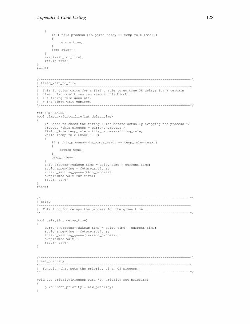
Appendix A Code Listing
128
{ if ( this_process->in_ports_ready == temp_rule->mask ) { return true; } temp_rule++; } swap(wait_for_fire); return true; } #endif /*----------------------------------------------------------------------------*\ | timed_wait_to_fire *-----------------------------------------------------------------------------* | This function waits for a firing rule to go true OR delays for a certain | time . Two conditions can remove this block: | + A firing rule goes off. | + The timed wait expires. \*----------------------------------------------------------------------------*/ #if (MTHREADED) bool timed_wait_to_fire(int delay_time) { /* Added to check the firing rules before actually swapping the process */ Process *this_process = current_process ; Firing_Rule temp_rule = this_process->firing_rule; while (temp_rule->mask != 0) { if ( this_process->in_ports_ready == temp_rule->mask ) { return true; } temp_rule++; } this_process->wakeup_time = delay_time + current_time; actions_pending = future_actions; insert_waiting_queue(this_process); swap(timed_wait_for_fire); return true; } #endif /*----------------------------------------------------------------------------*\ | delay *-----------------------------------------------------------------------------* | This function delays the process for the given time . \*----------------------------------------------------------------------------*/ bool delay(int delay_time) { current_process->wakeup_time = delay_time + current_time; actions_pending = future_actions; insert_waiting_queue(current_process); swap(timed_wait); return true; } /*----------------------------------------------------------------------------*\ | set_priority *-----------------------------------------------------------------------------* | Function that sets the priority of an OS process. \*----------------------------------------------------------------------------*/ void set_priority(Process_Data *p, Priority new_priority) { p->current_priority = new_priority; }

Appendix A Code Listing
129
/*=====================================================================================\ | OS_main.c *--------------------------------------------------------------------------------------\ | This file implements the important functions used by the kernel. It is the core file | of the kernel . \*====================================================================================*/ #include <signal.h> #include "ECO.h" extern EVENT_HANDLER event_handlers[]; extern OS_Process *OS_All_Process; extern Data_Channel *OS_All_DC; extern int NUM_DFG_NODES; /* Number of DFG Nodes */ extern int NUM_DFG_EDGES; /* Number of DFG Edges */ extern Process *delete_ready_queue(volatile int *); extern void insert_ready_queue(Process *,volatile int *); extern void allocate_initialize_DC(void); extern void allocate_initialize_process(void); extern void event_handler_1 (void); void allocate_space_datastruc(void); void initialize_thread(int); Process **ready_queue; /* Ready queue */ volatile int ready_queue_size = 0; /* Initializing the ready heap size */ Process *current_process=NULL; /* Points to the currently running */ /* process */ volatile Action_State actions_pending = no_actions; /* Handle time arrows events */ volatile int current_time; /* Holds the current timer value */ /* given by ISR */ Timed_Wait_Queue waiting_queue; /* Waiting queue for timed waits */ Event_Queue event_queue; /* Event queue (for interrupts) */ volatile int event_code=0; /* Holds event code from FPGA */ #if (MTHREADED) Context OS_env; /* Context saving space for the OS */ bool process_changed = true; /* Initialized to true for first */ /* thread */ Process *pcb; #endif /*----------------------------------------------------------------------------*\ | main *-----------------------------------------------------------------------------* | Main function for the kernel. Execution begins here. \*----------------------------------------------------------------------------*/ main() { int i; int index=1; /* Used in Static Scheduling */ int counter=0; log("Operating system starting ...\n\n") /* Calling the static scheduler */ if ( scheduler_routine != NULL ) { (*scheduler_routine)(); } allocate_initialize_DC(); allocate_initialize_process(); allocate_space_datastruc();

Appendix A Code Listing
130
#if (MTHREADED) for (i=0;i<NUM_DFG_NODES;i++) { initialize_thread(i); } #endif (*(event_handlers[0]))(); while (true) { /* Handle the interrupts and other actions */ if (actions_pending != no_actions) { if (waiting_queue.front != waiting_queue.rear) { handle_time_arrows(); } if (waiting_queue.front != waiting_queue.rear) //Not empty { actions_pending = future_actions; } else { actions_pending = no_actions; } if (event_queue.front != event_queue.rear) { handle_all_events(); } } /*------------------- For the Multi-threaded DARK -----------------------*/ #if (MTHREADED) if ( ready_queue_size > 0 ) { if (current_process == NULL) { current_process = delete_ready_queue(&ready_queue_size); process_changed = true; } else if ( (( (current_process->p).current_priority <= (ready_queue[1]-> p).current_priority) || (current_process->process_state != ready)) && !process_changed ) { /* change current process && NOT process changed added to */ /* leave the first process */ /* This case will arise only in case of an interrupt or */ /* after system call */ if (current_process->process_state == ready) { /* Save full context for the current process from the */ /* alternate register set. In other words convert */ /* shallow_setjmp buffer into a setjmp_all buffer */ convert_shallow_setjmp_to_all(&(current_process->process_env)); insert_ready_queue(current_process,&ready_queue_size); } current_process = delete_ready_queue(&ready_queue_size); process_changed = true; } /* Run the process */ if ( actions_pending != current_actions ) { if ( process_changed ) { process_changed = false; if ( shallow_setjmp(&OS_env) == 0 )
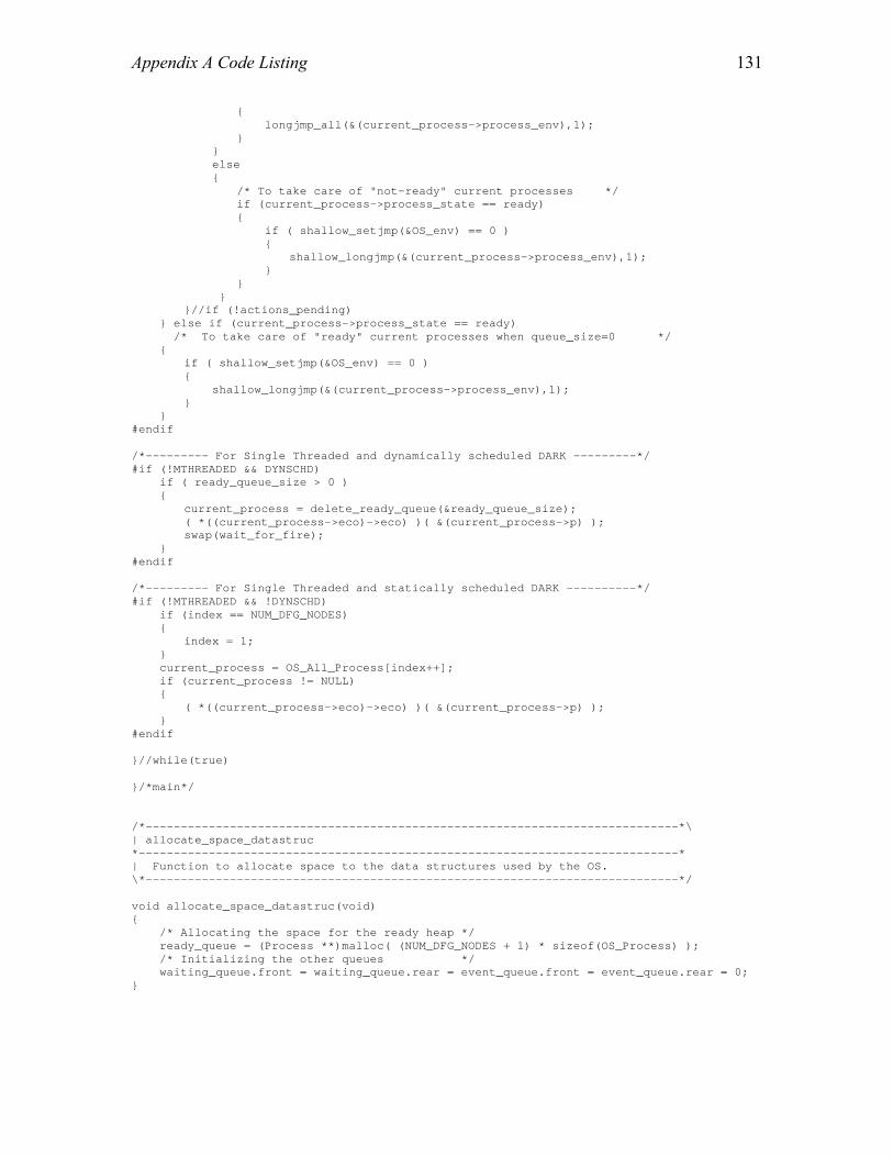
Appendix A Code Listing
131
{ longjmp_all(&(current_process->process_env),1); } } else { /* To take care of "not-ready" current processes */ if (current_process->process_state == ready) { if ( shallow_setjmp(&OS_env) == 0 ) { shallow_longjmp(&(current_process->process_env),1); } } } }//if (!actions_pending) } else if (current_process->process_state == ready) /* To take care of "ready" current processes when queue_size=0 */ { if ( shallow_setjmp(&OS_env) == 0 ) { shallow_longjmp(&(current_process->process_env),1); } } #endif /*--------- For Single Threaded and dynamically scheduled DARK ---------*/ #if (!MTHREADED && DYNSCHD) if ( ready_queue_size > 0 ) { current_process = delete_ready_queue(&ready_queue_size); ( *((current_process->eco)->eco) )( &(current_process->p) ); swap(wait_for_fire); } #endif /*--------- For Single Threaded and statically scheduled DARK ----------*/ #if (!MTHREADED && !DYNSCHD) if (index == NUM_DFG_NODES) { index = 1; } current_process = OS_All_Process[index++]; if (current_process != NULL) { ( *((current_process->eco)->eco) )( &(current_process->p) ); } #endif }//while(true) }/*main*/ /*----------------------------------------------------------------------------*\ | allocate_space_datastruc *-----------------------------------------------------------------------------* | Function to allocate space to the data structures used by the OS. \*----------------------------------------------------------------------------*/ void allocate_space_datastruc(void) { /* Allocating the space for the ready heap */ ready_queue = (Process **)malloc( (NUM_DFG_NODES + 1) * sizeof(OS_Process) ); /* Initializing the other queues */ waiting_queue.front = waiting_queue.rear = event_queue.front = event_queue.rear = 0; }

Appendix A Code Listing
132
/*----------------------------------------------------------------------------*\ | initialize_thread *-----------------------------------------------------------------------------* | Function to initialize the stack pointers and start running the thread for | the first time. Required only in case of Multi-threaded DARK \*----------------------------------------------------------------------------*/ #if (MTHREADED) void initialize_thread(int process_id) { unsigned int *ptrfront_stk, *ptrend_stk; pcb = OS_All_Process[process_id]; ptrfront_stk = pcb->stack_pointer; ptrend_stk = pcb->stack_pointer + pcb->stack_size - 1; if (pcb == NULL) //In case of ISRs { return; } if ( setjmp_all(&OS_env) != 0 ) { return; } /* Initializing the stack pointers */ /* At this point we can use any of the data registers because their */ /* content is redundant */ asm( "r1 = %0;" : : "d" (ptrfront_stk) : "r1" ); asm( "r5 = %0;" : : "d" (pcb->stack_size) : "r5" ); asm( "r9 = %0;" : : "d" (ptrend_stk) : "r9" ); asm( "b6 = r1;" ); asm( "b7 = r1;" ); asm( "l6 = r5;" ); asm( "l7 = r5;" ); asm( "I6 = r9;" ); asm( "I7 = r9;" ); if ( setjmp_initialize(&(pcb->process_env)) == 0 ) { longjmp_all(&OS_env,1); } /* Execute the ECO function with the Process_data as the parameter */ ( *((current_process->eco)->eco) )( &(current_process->p) ); swap(dead); } #endif

133
Vita Kuljeet Singh was born in Calcutta, India on February 17, 1978. He completed his BE from Birla Institute of Technology, Ranchi, India in May, 1999. As an undergraduate, he developed new design of hardware for a modem that used QAPSK encoding. After working as a DBA for Tata Consultancy Services, India for a year, he joined University of Houston, Texas for pursuing graduate studies in August 2000. He transferred to Virginia Polytechnic Institute and State University in January 2001 and will be graduating with a Master of Science degree in Computer Science in December 2002. He is currently working as an Embedded Software Design Engineer for GE Fanuc Automation, North America.