design and development of the kef r109 / ‘the maidstone ... · pdf filethis report is a...
TRANSCRIPT

Design and development of the
KEF R109 / ‘The Maidstone’ Loudspeaker

Introduction
This report is a technical discussion on the design and development of the KEFReference 109 / ’The Maidstone’ loudspeaker system. It outlines the principles andgoals behind the new system and describes the various technical methods used toachieve them.
For the last four years the KEF Reference Series has demonstrated to the marketplacethe KEF philosophy of loudspeaker design, namely that superior sound quality comesthrough careful, thorough technical design and good production techniques. This rangeof speakers is designed around two of KEFs technical innovations: the ‘Uni-Q’coincident source midrange/high frequency driver array, and the ‘Coupled Cavity’ lowfrequency system. Another KEF feature, the ‘Systems Approach’, is used to specifywhat would be the ideal behaviour of the system: the component parts of drivers,cabinets and crossover network then being designed and optimised to meet this target.All production pairs are carefully assembled and tested in production to ensure thecustomer receives a pair of loudspeakers that are indistinguishable from the ‘DesignReference’.
The Uni-Q driver array has demonstrated the superior stereo imaging that comes fromthe midrange and high frequency drivers being at the same point in space, and theInter-Port Coupled Cavity band-pass low frequency method has displayed its lowdistortion, high output characteristics which in twin driver form lends itself beautifullyto the tall slim enclosures so popular in the modern environment. With the Referencerange firmly established as a benchmark in the marketplace the opportunity arose todesign a new system that would take the company one step closer to its goal of perfectsound reproduction. That system would become the Reference 109/Maidstone.
System concept
Subjective and Objective Targets
The R109/Maidstone system had a serious goal - to reproduce the full bandwidth anddynamics of music signals. When developing larger speakers the aim is for the systemto go louder with more low frequency extension, with greater accuracy, lowerdistortion and lower colouration. A compromise in one of these is not acceptable. Thecombination of more LF extension and greater output level puts a double target on thelow frequency system - it means a big increase in the ‘volume throw’ of the LFradiators, the volume of air that must be displaced at maximum output. Lowercolouration means a rigorous analysis of the motion of diaphragms, enclosure walls

and the sound fields within the enclosures. The maximum output target also places ademand on the input impedance of the system - to reach its maximum output level theloudspeaker must not demand more current than a good amplifier can provide. Overallthen, the ‘Systems Approach’ needs to be taken to the design of a loudspeaker of thistype - a design methodology that KEF has used successfully for many years.
Examining Current Technology
A rigorous analysis of the Reference range revealed that the 4th generation Uni-Qdriver array was a significant step forward from previous models. Both the imagingand tonal balance were greatly improved, further demonstrating the fundamental‘rightness’ of the coincident source principle. This was a Uni-Q design that would givesuperior performance in KEF systems for a considerable time.
Figure 1. Laser scan of the midrange cone in the SP1415 Uni-Q driver array. The scanshows the motion of the cone at 3.1 kHz. Bending waves in the cone travel outwardsfrom the coil to the surround where they are damped-out by the lossy surroundmaterial. This gentle ‘ripple’ effect is the ideal behaviour known as ‘controlled break-up’.

Taking a close look at the low frequency end of the spectrum revealed that the ‘Inter-port’ Coupled Cavity system was fulfilling its role of providing accurate, well definedbass in a compact enclosure. However, when the possibility of designing a new High-End Uni-Q based system came along the KEF engineers thought long and hard aboutthe best way of reproducing the frequency range below 400Hz. Without any majorconstraints on system cost and the physical size and shape of the cabinet, a number ofserious possibilities arise. Concepts used in older KEF speakers like the Reference 105and KM1, for example, were re-evaluated to test their suitability. Finally a decisionwas made, the R109 would use direct radiators for the low frequency and lowermidrange. New drive units would be specially designed to best exploit the directradiator principle.
Sorting the Format
To best exploit the benefits of the Uni-Q driver array it is used only for frequenciesabove 400Hz. This limits the movement of the midrange cone the absolute minimum,thus reducing distortion and eliminating any possibility of the high frequency radiationbeing influenced by a ‘moving boundary’.
The low frequency end of the spectrum needs to be considered from a number ofstandpoints. The system must achieve a given target for the low frequency roll-off. Thekey points are (i) extension (-6dB point), (ii) damping (shape of the roll-off), and (iii)the maximum output level (for a given distortion level). It was decided that a single,top quality 15” driver in a reflex enclosure would be ideal.
To operate the 15” woofer right up to the midrange crossover at 400Hz would not bea good solution, the step between the 15” and 6” units would be too subjectivelyobvious. A lower midrange unit is therefore the correct way to go, and a similaranalysis of excursion requirements relative to distortion and cleanness of the sound atthe upper crossover point lead to the decision to go for a single 10” unit in a sealedenclosure.
The system format is then fixed: a 15” reflex up to 100Hz, a 10” sealed from 100 to400Hz and the Uni-Q driver array from 400Hz to 20kHz with a mid/treble crossover at3kHz. The designers were then able to start work on the new drivers, using all thelatest modelling techniques to optimise all the various parts.

Designing the new SP1405 15” and SP1406 10” units.
KEF has a long and illustrious history of designing and developing market leadingdrive units utilising the latest in materials technology and production techniques.Classic units like the B139, B110 and T27 right up to the latest developments inneodimium magnets which lead to the Uni-Q drive unit array. KEF is at the forefront inusing Finite Element Modelling for the analysis of loudspeaker components. The bassunit magnet structures, for example, were modelled using this technique. The facility isalso available to analyse enclosure vibrations, diaphragm behaviour and acousticradiation.
Drive Unit designer Enrico Cecconi

SP1405 Low Frequency Unit
A key decision was taken very early on in the design process - both units would usethe short coil-long gap motor system. In this method the coil is always within theconstant region of the magnetic field thus achieving lower distortion for the sameexcursion. This is often viewed as an expensive technology but the use of FEAtechniques allows the unit to be designed in the most efficient way. The metal parts arespecially shaped to give optimum control of the magnetic field around the critical gapregion.
Figure 2. Cross-section of the new SP1405 Low Frequency Unit.
The SP1405 gains extra performance by using a double suspension, this gives extrastability and ensures pure piston motion with no ‘rocking’. The diaphragm is made of aspecial treated paper compound, still an excellent cone material when carefullydesigned. The diaphragm is conical in shape for rigidity, and terminated with a robustrubber surround which does not deform at high levels. The diaphragm displays theideal characteristic of low frequency units, pure piston motion, well beyond the 100Hzcrossover to the lower midrange unit. The unit is housed in a rigid cast aluminiumchassis which when securely mounted allows the moving parts to act as in ideal fashionwith minimal mechanical energy leaking into the solid structure.

Figure 3. Laser scan of the SP1405 bass unit at 300Hz. The slight deformation of thesurround is the first indication of non-piston behaviour, this is well above the crossoverpoint of 100Hz.
SP1406 Lower Midrange
The SP1406 also uses a short coil-long gap motor system, treated paper cone and castaluminium chassis. In addition it has an edgewound coil which provides greaterstiffness of the coil structure. Its role in the R109 as a dedicated lower midrange drivermeans a slightly different approach is taken from the SP1405. The diaphragmbehaviour at the higher frequencies becomes more critical, a balance must be achievedbetween piston motion in the passband (100 to 400Hz) and controlled break-up at thehigher frequencies, as the unit rolls-off and crosses over to the Uni-Q array.
Designing the cabinets
The aim of the cabinet design is very simple: it must rigidly hold the units in space sothat the only moving parts are the diaphragms (and air motion in the ports), theradiation from the rear of the diaphragms should be properly controlled and notinterfere with the front radiation and the baffle design should aid the even dispersion ofsound into the listening room.

Figure 4. The first break-up mode in the SP1406 lower midrange unit is at 560Hzwhere the surround displays controlled resonance.
The R109 has a ‘modular’ construction: each unit has its own separate cabinet tominimise coupling effects, the radiation from each section should then be independentof the others, each cabinet then being optimised to be a rigid structure. With eachcabinet designed to be a rigid structure the three cabinets can then be assembled withminimal risk of interaction. Even so, where the cabinets meet they do so via a finitepoint coupling technique, which minimises the contact area between them. The LFmodule couples to the floor via four spiked feet and provides a stable platform for theLMF and Uni-Q modules which are rigidly coupled together and mount on the LFmodule via three spiked feet. To give time alignment of the drivers the whole system istilted back by 6 degrees.
The attention to detail extends to the internal structure of the cabinets. All of them aremade from MDF, 25mm throughout except for the LF baffle, which is 50mm, toensure a solid mounting surface for the SP1405 15” unit which alone weighs 17.5kg.Each cabinet is extensively braced for rigidity, which is further increased by thecurvature of the front and back panels.

Figure 5. Comparison of the performance of braced and unbraced Uni-Q cabinets. Thedata is the velocity of front panel vibration due to excitation from the Uni-Q driverarray. The braced cabinet (solid line) shows considerable improvement at 250Hz, 1kHzand 1.4kHz.
Internal acoustic damping is critically judged for each section. There are three reasonsfor having acoustic damping in the enclosures (i) to absorb standing waves (ii) toabsorb travelling waves at the higher frequencies, and (3) to add damping to the LFroll-off. In the R109 the LF section has no damping - it is not required at such lowfrequencies and is only going to create an acoustical impedance mixture which willover-damp the roll-off. The lower midrange section has a medium filling of BAFwadding, just enough to kill the standing waves but not enough to thicken and slowthe sound. The Uni-Q section has a combination of foam around the unit and waddingto the sides. The choice of damping is determined as much by listening as bymeasurement.
The width of the front baffle is determined by the size of the 15” driver, this dimensionis carried up onto the lower midrange and Uni-Q modules. There are obvious cosmeticreasons for doing this, but it also functions well acoustically. There are certain baffleshapes which work well acoustically and some which don’t, the main theoreticalsolutions being the ‘piston in the end of a tube’, the ‘piston in a sphere’ and the‘infinite baffle’. In reality one is always dealing with something in between these so it isnecessary to fully investigate the effects the baffle is going to have on the systemperformance. Finite Element techniques can be used to model the behaviour of thebaffle and allow the designer to get the best result from a particular concept. KEF hasused similar shaped baffles before, as in the 200C centre channel and the Reference
105/3 (albeit vertically rather than horizontally). In the case of the R109 the baffle iscurved back towards the sides to reduce the effect of diffraction from the cabinetedges. The result is a baffle shape that is more directional than average below 1kHzbut contributes to a smooth Uni-Q off-axis performance at the higher frequencies.
The increased directivity below 1kHz adds to the unique sound of the R109. Normallyin a slim enclosure the system has wide dispersion up to around 1kHz, becomingprogressively more directional as the frequency increases (due to driver directionality).The wide baffle of the R109 imparts an extra directivity on the lower midrange sectionwhich helps to match it to that of the Uni-Q section. This means the system directivityis controlled over a much wider frequency range than a conventional slim speaker. Theresult is an increase in the ratio of direct to reveberrant sound, thus increasing clarityand reducing the influence of the listening room. The uniformity of the dispersionpattern with frequency contributes to the R109’s incredibly ‘life-like’ reproduction.
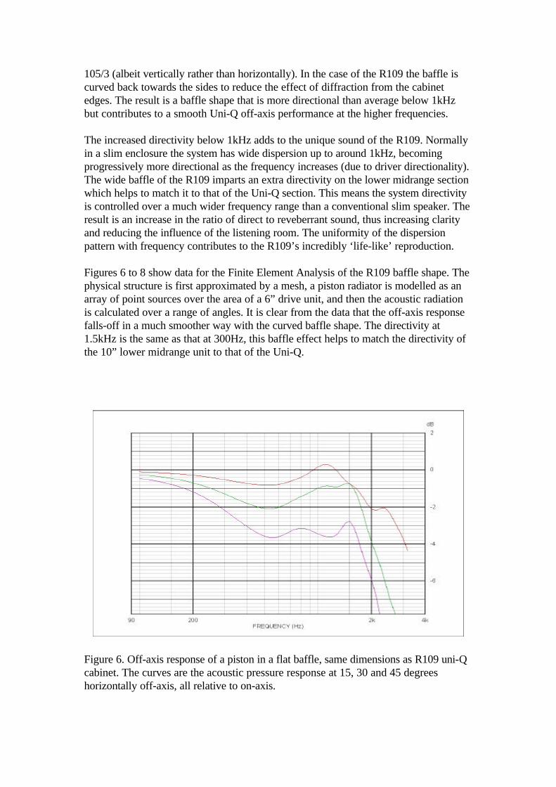
Figures 6 to 8 show data for the Finite Element Analysis of the R109 baffle shape. Thephysical structure is first approximated by a mesh, a piston radiator is modelled as anarray of point sources over the area of a 6” drive unit, and then the acoustic radiationis calculated over a range of angles. It is clear from the data that the off-axis responsefalls-off in a much smoother way with the curved baffle shape. The directivity at1.5kHz is the same as that at 300Hz, this baffle effect helps to match the directivity ofthe 10” lower midrange unit to that of the Uni-Q.
Figure 6. Off-axis response of a piston in a flat baffle, same dimensions as R109 uni-Qcabinet. The curves are the acoustic pressure response at 15, 30 and 45 degreeshorizontally off-axis, all relative to on-axis.

Figure 7. Finite Element Model of the Uni-Q enclosure.
Figure 8. Off-axis response of a piston in R109 uni-Q cabinet. The curves are theacoustic pressure response at 15, 30 and 45 degrees horizontally off-axis, all relative toon-axis.

Crossover Network Design
The function of the crossover network is to integrate the outputs of the four driveunits to provide a system response that meets the idealised target function. After initialstudies it was decided to use a fourth order acoustical crossover for the Uni-Q section,second order between lower midrange and Uni-Q and an asymmetrical fourth/secondorder between the low frequency and lower midrange. Once the drive units aremounted in the enclosures and their acoustic responses measured the data isdownloaded onto the computer system where a suite of design packages allow theengineer to set about the network design. Target functions are specified for eachsection of the network and a combination of computer optimization and ‘hands-on’adjustment and tweaking by the engineers leads to a theoretical solution for thenetwork which can then be built up for testing and listening.
System designer Andrew Watson
The network is designed to be as efficient as possible with no superfluous componentsin the signal path. Component choice is important in maintaining the highest soundquality. Polypropylene capacitors with their reduced loss factors are used whereverpossible as are air cored inductors, preferable to ferrite cores due the lack of saturation


Figure 10. Individual unit responses and Input Impedance.
Extra features
Included on the system is a facility to tilt the high frequency output from 5 to 20kHzby +/-1dB. This has been found to be useful in matching the system to particularlistening environments. Also included is the facility to bypass the internal passivecrossover and replace it with an active crossover system. All drive unit inputs can beaccessed directly and the user is free to experiment with their own electronic filters.Attention to fine detail means careful thought has gone into all the fixtures and fittingson the system such as terminals, shorting bars, spikes, cups and cones etc. All parts aregold plated for sonic integrity.
Summary
The R109 has been several years in the making. During that time the KEF engineershave studied all aspects of loudspeaker design to create a loudspeaker that canjustifiably be rated as one of the best in the world. It is a loudspeaker for thecommitted music listener who demands a system that can faithfully reproduce the fullbandwidth and dynamics of musical signals.
A.P.Watson, September 1999.
