design and development of the 2002 uc davis...
TRANSCRIPT

Design and Development of the 2002 UC Davis FutureTruck
Nathaniel Meyr, Christopher Cardé, Christopher Nitta, Dahlia Garas, Tyler Garrard, Jason Parks, James Vaughn, Charnjiv Bangar, Avernethy Francisco,
Mark Duvall and Andrew Frank University of California, Davis
ABSTRACT
Yosemite is an advanced hybrid electric vehicle built on the Ford U152 Explorer platform. The University of California, Davis, FutureTruck team designed Yosemite to meet the following objectives:
1. Maximize vehicle energy efficiency 2. Minimize petroleum consumption 3. Reduce fuel cycle greenhouse gas emissions 4. Achieve California Super Ultra Low Emission Vehicle
(SULEV) target 5. Deliver class-leading performance The University of California, Davis FutureTruck team redesigned a 2002 Ford Explorer as a Hybrid Electric Vehicle to meet the following goals: reduce fuel cycle greenhouse gas emissions by 67%, double the fuel economy of a stock Explorer, meet California’s Super Ultra Low Emissions Vehicle standard, and qualify for substantial Partial Zero Emissions Vehicle credits in California. Yosemite meets these goals with an efficient flexible fuel hybrid powertrain, improved component systems, and an advanced control system.
Yosemite incorporates two independent powertrains to provide four-wheel drive and achieve stock towing capacity. The primary powertrain combines a 1.9L flexible fuel engine with a 75 kW brushless DC motor driving the rear wheels. This powertrain configuration is simple, compact, reliable, and allows flexibility in control strategy. The secondary powertrain is a 60 kW AC induction motor and reduction transaxle gearbox. Together, the two powertrains allow Yosemite to achieve high efficiency under normal operating conditions while matching stock vehicle performance. A 16.5 kWh nickel metal hydride traction battery pack powers the electric motors, providing up to 50 miles of all-electric range. Yosemite’s superior fuel economy, low cost of operation, and performance, combined with advanced composites, telematics systems, and other consumer features make it a desirable and competitive vehicle in today’s market.
INTRODUCTION
The University of California, Davis FutureTruck team is participating in the 2002 FutureTruck competition, sponsored by Ford Motor Company and the U.S. Department of Energy. In response to international
concern regarding the potential of Greenhouse Gas (GHG) emissions to cause global warming, the competition challenges student teams to redesign a midsize Sport Utility Vehicle (SUV) as a Hybrid Electric Vehicle (HEV), reducing equivalent Greenhouse Gas Index (GHGI), criteria tailpipe emissions, and fuel consumption. These goals must be met without compromising vehicle safety, performance, utility, or value. In addition, UC Davis focuses on qualifying for 80% Partial Zero Emissions Vehicle (PZEV) credit under the California Low Emissions Vehicle II amendment1. UC Davis will compete in the 2002 FutureTruck competition with Yosemite, a redesigned 2002 Ford Explorer.
illustrates the vehicle’s configuration and lists the team’s design goals for 2002.
Figure 1
Figure 1. Yosemite design layout.
Table 1
Table 1. Yosemite design goals
Greenhouse Gas Emissions Reduce by 67% Petroleum Consumption Reduce by 80% Fuel Economy 30 mpgge 0-60 mph acceleration 7.0 seconds Emissions California SULEV
The FutureTruck Challenge’s emphasis on reducing greenhouse gases (CO2, CH4, and N2O) suggests the use of electricity as the primary fuel due to its low fuel-cycle emissions2. A charge-depletion control strategy maximizes electricity usage by using energy from off-board charging. The vehicle automatically shifts to a

Fuel Selection charge-sustaining mode during extended use and while towing a trailer. In addition to improved efficiency, Yosemite also demonstrates excellent acceleration, competitive towing capacity, an advanced driver interface, and four-wheel drive (4WD) capability.
Electricity and E85 (85% Ethanol, 15% gasoline) were chosen as Yosemite‘s primary fuels. Yosemite’s flexible fuel capability also allows the use of Reformulated Gasoline (RFG). The GREET (Greenhouse Gases, Regulated Emissions, and Energy use in Transportation) model version 1.5a indicates that the use of electricity as vehicle fuel can significantly reduce the greenhouse gas production associated with automobiles. The use of a flex fuel spark ignition engine allows the vehicle to meet the desired range of 400 miles.
DESIGN PHILOSOPHY
Hybrid Configuration Three powertrain configurations dominate HEV research. They are the parallel, series and dual-hybrid. Ongoing research at the UC Davis HEV Center has demonstrated that a parallel hybrid configuration is the best choice for the Yosemite powertrain. A series hybrid configuration was not chosen because it requires chemical energy to be converted to electrical energy before it drives the wheels, resulting in unnecessary inefficient energy conversions. While a dual hybrid design has lower conversion losses than a series configuration, it is costly and mechanically more complex.
Energy Management Strategy Yosemite is drivable as an EV, a conventional vehicle or as an HEV. Driving the vehicle on electric energy is ideal since local emissions for the vehicle are zero. However, the use of electricity is not practical for steady state long-distance driving on highways. Rather, electricity usage should be reserved for city-driving conditions to eliminate ICE idle and inefficient low-power operating regions of the ICE. Additionally, zero local emissions from to EV operation benefit the air quality of densely populated regions.
A charge depletion parallel hybrid design allows for more efficient power transfer from available power sources as well as mechanical and control simplicity. The parallel hybrid configuration has other distinct advantages. Since the internal combustion engine (ICE) and electric motor (EM) drive the vehicle in tandem, the size of the ICE can be greatly reduced in comparison to the stock vehicle. This reduction is possible because the ICE is sized to meet steady state highway loads while the EM is used for low speed driving and transient conditions. Reducing the engine size allows the engine to operate at higher average thermal efficiency and within its ideal operating region, increasing fuel economy.
The UC Davis HEV center has devised an energy management strategy to maximize the EV distance traveled while maintaining the range of a conventional vehicle. All operating conditions fall under two energy management strategies: a charge-depleting strategy and a charge-sustaining strategy. The charge-depleting strategy allows the traction battery state of charge (SOC) to deplete. In contrast, the control system actively maintains the traction battery SOC during charge-sustaining operation. The vehicle uses a charge-depleting strategy when the traction battery SOC is greater than 10%. During charge-depleting operation, the ICE only turns on when the vehicle speed has exceeded 45 mph. The turn on speed is chosen to statistically maximize vehicle kilometers traveled. The ICE handles the steady state power requirement and the EM assists when the driver commands heavy acceleration. During the charge-depletion mode only the energy recovered through regenerative braking charges the traction battery. Regenerative braking uses the EM as a generator to capture the power that otherwise would be lost in the mechanical braking system.
A plug-in HEV reduces local vehicle emissions and maximizes vehicle energy efficiency. To achieve these goals, a plug-in HEV utilizes a high capacity battery pack and a powerful electric drive system. Yosemite’s control strategy attempts to operate as an electric vehicle (EV) in urban driving. During higher speed driving, the IC engine provides steady-state power while the electric drive system meets transient acceleration demands. The size of the battery pack is based on National Personal Transportation Statistics (NPTS) that indicated that over 80% of US motorists drive 50 miles or less daily3. To maximize all-electric distance traveled, the traction battery is sized for 50 miles of electric vehicle range.
The vehicle transitions to charge-sustaining mode once the vehicle’s SOC has depleted to 10% as shown in
. In this mode, the ICE turn on speed is reduced to 15 mph in order to conserve traction battery energy. During this mode of operation, the ICE generates more power than the driver requests. The EM captures the extra power to maintain traction battery SOC.
To achieve 4WD capability, an all-electric front powertrain was chosen to maximize regenerative braking efficiency. The use of an all-electric front powertrain also met packaging constraints, and eliminated energy losses typical in a mechanical transfer case.
Figure 2
2
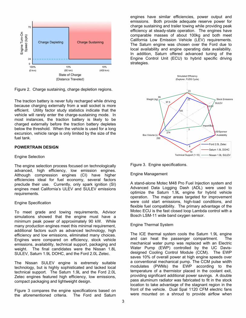
Figure 2. Charge sustaining, charge depletion regions.
The traction battery is never fully recharged while driving because charging externally from a wall socket is more efficient. Utility factor study statistics indicate that the vehicle will rarely enter the charge-sustaining mode. In most instances, the traction battery is likely to be charged externally before the traction battery depletes below the threshold. When the vehicle is used for a long excursion, vehicle range is only limited by the size of the fuel tank. POWERTRAIN DESIGN
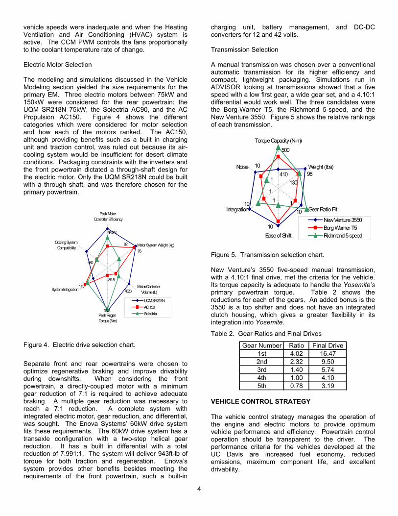
Engine Selection The engine selection process focused on technologically advanced, high efficiency, low emission engines. Although compression engines (CI) have higher efficiencies ideal for fuel economy, several factors preclude their use. Currently, only spark ignition (SI) engines meet California’s ULEV and SULEV emissions requirements. Engine Specification To meet grade and towing requirements, Advisor simulations showed that the engine must have a minimum peak power of approximately 90 kW. While many production engines meet this minimal requirement, additional factors such as advanced technology, high efficiency and low emissions, eliminated many choices. Engines were compared on efficiency, stock vehicle emissions, availability, technical support, packaging and weight. The final candidates were the Nissan 1.8L SULEV, Saturn 1.9L DOHC, and the Ford 2.0L Zetec. The Nissan SULEV engine is extremely suitable technology, but is highly sophisticated and lacked local technical support. The Saturn 1.9L and the Ford 2.0L Zetec engines featured high efficiency, low emissions, compact packaging and lightweight design. Figure 3
22
105
8
97.5
ULEV
US/Sponsor
10
250
23
95
SULEV
Import/Buy3
274
Simulated Efficiency(Explorer, FUDS Cycle)
Stock Emissions
Availability
Technical Support (1-10)
Box Volume (L)
Weight (kg)
Ford 2.0L Zetec
Saturn 1.9L DOHC
Nissan 1.8L SULEV
Figure 3. Engine specifications.
compares the engine specifications based on the aforementioned criteria. The Ford and Saturn
engines have similar efficiencies, power output and emissions. Both provide adequate reserve power for charge sustaining and trailer towing while providing peak efficiency at steady-state operation. The engines have comparable masses of about 100kg and both meet California Low Emission Vehicle (LEV) requirements. The Saturn engine was chosen over the Ford due to local availability and engine operating data availability. In addition, Saturn offered advanced tuning of the Engine Control Unit (ECU) to hybrid specific driving strategies.
Engine Management A stand-alone Motec M48 Pro Fuel Injection system and Advanced Data Logging Dash (ADL) were used to optimize the Saturn 1.9L engine for hybrid vehicle operation. The major areas targeted for improvement were cold start emissions, high-load conditions, and flexible fuel compatibility. The primary advantage of the Motec ECU is the fast closed loop Lambda control with a Bosch LSM-11 wide band oxygen sensor. Engine Thermal System The ICE thermal system cools the Saturn 1.9L engine and can heat the passenger compartment. The mechanical water pump was replaced with an Electric Water Pump (EWP) controlled by the UC Davis-designed Cooling Control Module (CCM). The EWP saves 10% of overall power at high engine speeds over a conventional mechanical pump. The CCM pulse width modulates (PWMs) the EWP according to the temperature of a thermistor placed in the coolant exit, providing significant additional power savings. A double pass aluminum radiator was fabricated to fit in the stock location to take advantage of the stagnant region in the front of the vehicle. Dual Spal 1120 CFM electric fans were mounted on a shroud to provide airflow when
3
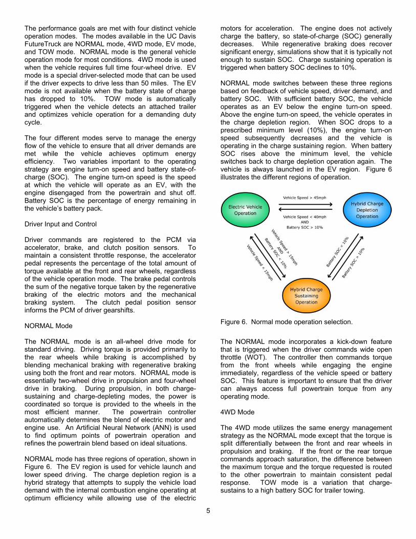
vehicle speeds were inadequate and when the Heating Ventilation and Air Conditioning (HVAC) system is active. The CCM PWM controls the fans proportionally to the coolant temperature rate of change. Electric Motor Selection The modeling and simulations discussed in the Vehicle Modeling section yielded the size requirements for the primary EM. Three electric motors between 75kW and 150kW were considered for the rear powertrain: the UQM SR218N 75kW, the Solectria AC90, and the AC Propulsion AC150. Figure 4 shows the different categories which were considered for motor selection and how each of the motors ranked. The AC150, although providing benefits such as a built in charging unit and traction control, was ruled out because its air-cooling system would be insufficient for desert climate conditions. Packaging constraints with the inverters and the front powertrain dictated a through-shaft design for the electric motor. Only the UQM SR218N could be built with a through shaft, and was therefore chosen for the primary powertrain.
33.8
480
76
96.8%
7623
89.5115
82
Peak Motor Controller Efficiency
Motor System Weight (kg)
Motor/Controller Volume (L)
Peak Regen Torque (Nm)
System Integration
Cooling System Compatibility
UQM SR218NAC 150Solectria
Figure 4. Electric drive selection chart.
Separate front and rear powertrains were chosen to optimize regenerative braking and improve drivability during downshifts. When considering the front powertrain, a directly-coupled motor with a minimum gear reduction of 7:1 is required to achieve adequate braking. A multiple gear reduction was necessary to reach a 7:1 reduction. A complete system with integrated electric motor, gear reduction, and differential, was sought. The Enova Systems’ 60kW drive system fits these requirements. The 60kW drive system has a transaxle configuration with a two-step helical gear reduction. It has a built in differential with a total reduction of 7.991:1. The system will deliver 943ft-lb of torque for both traction and regeneration. Enova’s system provides other benefits besides meeting the requirements of the front powertrain, such a built-in
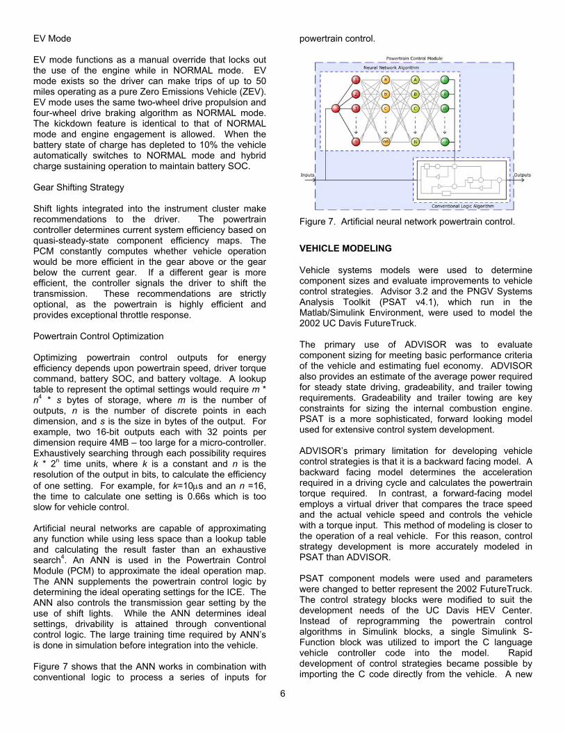
charging unit, battery management, and DC-DC converters for 12 and 42 volts. Transmission Selection A manual transmission was chosen over a conventional automatic transmission for its higher efficiency and compact, lightweight packaging. Simulations run in ADVISOR looking at transmissions showed that a five speed with a low first gear, a wide gear set, and a 4.10:1 differential would work well. The three candidates were the Borg-Warner T5, the Richmond 5-speed, and the New Venture 3550. Figure 5 shows the relative rankings of each transmission.
10
410 9810
10
10
1 1301
500
1 1
Torque Capacity (N-m)
Weight (lbs)
Gear Ratio Fit
Ease of Shift
Integration
Noise
New Venture 3550Borg Warner T5Richmand 5 speed
Figure 5. Transmission selection chart. New Venture’s 3550 five-speed manual transmission, with a 4.10:1 final drive, met the criteria for the vehicle. Its torque capacity is adequate to handle the Yosemite’s primary powertrain torque. Table 2 shows the reductions for each of the gears. An added bonus is the 3550 is a top shifter and does not have an integrated clutch housing, which gives a greater flexibility in its integration into Yosemite.
Table 2. Gear Ratios and Final Drives
Gear Number Ratio Final Drive1st 4.02 16.472nd 2.32 9.503rd 1.40 5.744th 1.00 4.105th 0.78 3.19
VEHICLE CONTROL STRATEGY
The vehicle control strategy manages the operation of the engine and electric motors to provide optimum vehicle performance and efficiency. Powertrain control operation should be transparent to the driver. The performance criteria for the vehicles developed at the UC Davis are increased fuel economy, reduced emissions, maximum component life, and excellent drivability.
4
The performance goals are met with four distinct vehicle operation modes. The modes available in the UC Davis FutureTruck are NORMAL mode, 4WD mode, EV mode, and TOW mode. NORMAL mode is the general vehicle operation mode for most conditions. 4WD mode is used when the vehicle requires full time four-wheel drive. EV mode is a special driver-selected mode that can be used if the driver expects to drive less than 50 miles. The EV mode is not available when the battery state of charge has dropped to 10%. TOW mode is automatically triggered when the vehicle detects an attached trailer and optimizes vehicle operation for a demanding duty cycle. The four different modes serve to manage the energy flow of the vehicle to ensure that all driver demands are met while the vehicle achieves optimum energy efficiency. Two variables important to the operating strategy are engine turn-on speed and battery state-of-charge (SOC). The engine turn-on speed is the speed at which the vehicle will operate as an EV, with the engine disengaged from the powertrain and shut off. Battery SOC is the percentage of energy remaining in the vehicle’s battery pack. Driver Input and Control Driver commands are registered to the PCM via accelerator, brake, and clutch position sensors. To maintain a consistent throttle response, the accelerator pedal represents the percentage of the total amount of torque available at the front and rear wheels, regardless of the vehicle operation mode. The brake pedal controls the sum of the negative torque taken by the regenerative braking of the electric motors and the mechanical braking system. The clutch pedal position sensor informs the PCM of driver gearshifts. NORMAL Mode The NORMAL mode is an all-wheel drive mode for standard driving. Driving torque is provided primarily to the rear wheels while braking is accomplished by blending mechanical braking with regenerative braking using both the front and rear motors. NORMAL mode is essentially two-wheel drive in propulsion and four-wheel drive in braking. During propulsion, in both charge-sustaining and charge-depleting modes, the power is coordinated so torque is provided to the wheels in the most efficient manner. The powertrain controller automatically determines the blend of electric motor and engine use. An Artificial Neural Network (ANN) is used to find optimum points of powertrain operation and refines the powertrain blend based on ideal situations. NORMAL mode has three regions of operation, shown in
. The EV region is used for vehicle launch and lower speed driving. The charge depletion region is a hybrid strategy that attempts to supply the vehicle load demand with the internal combustion engine operating at optimum efficiency while allowing use of the electric
motors for acceleration. The engine does not actively charge the battery, so state-of-charge (SOC) generally decreases. While regenerative braking does recover significant energy, simulations show that it is typically not enough to sustain SOC. Charge sustaining operation is triggered when battery SOC declines to 10%. NORMAL mode switches between these three regions based on feedback of vehicle speed, driver demand, and battery SOC. With sufficient battery SOC, the vehicle operates as an EV below the engine turn-on speed. Above the engine turn-on speed, the vehicle operates in the charge depletion region. When SOC drops to a prescribed minimum level (10%), the engine turn-on speed subsequently decreases and the vehicle is operating in the charge sustaining region. When battery SOC rises above the minimum level, the vehicle switches back to charge depletion operation again. The vehicle is always launched in the EV region. Figure 6 illustrates the different regions of operation.
Figure 6
Figure 6. Normal mode operation selection.
The NORMAL mode incorporates a kick-down feature that is triggered when the driver commands wide open throttle (WOT). The controller then commands torque from the front wheels while engaging the engine immediately, regardless of the vehicle speed or battery SOC. This feature is important to ensure that the driver can always access full powertrain torque from any operating mode. 4WD Mode The 4WD mode utilizes the same energy management strategy as the NORMAL mode except that the torque is split differentially between the front and rear wheels in propulsion and braking. If the front or the rear torque commands approach saturation, the difference between the maximum torque and the torque requested is routed to the other powertrain to maintain consistent pedal response. TOW mode is a variation that charge-sustains to a high battery SOC for trailer towing.
5
EV Mode EV mode functions as a manual override that locks out the use of the engine while in NORMAL mode. EV mode exists so the driver can make trips of up to 50 miles operating as a pure Zero Emissions Vehicle (ZEV). EV mode uses the same two-wheel drive propulsion and four-wheel drive braking algorithm as NORMAL mode. The kickdown feature is identical to that of NORMAL mode and engine engagement is allowed. When the battery state of charge has depleted to 10% the vehicle automatically switches to NORMAL mode and hybrid charge sustaining operation to maintain battery SOC. Gear Shifting Strategy Shift lights integrated into the instrument cluster make recommendations to the driver. The powertrain controller determines current system efficiency based on quasi-steady-state component efficiency maps. The PCM constantly computes whether vehicle operation would be more efficient in the gear above or the gear below the current gear. If a different gear is more efficient, the controller signals the driver to shift the transmission. These recommendations are strictly optional, as the powertrain is highly efficient and provides exceptional throttle response. Powertrain Control Optimization Optimizing powertrain control outputs for energy efficiency depends upon powertrain speed, driver torque command, battery SOC, and battery voltage. A lookup table to represent the optimal settings would require m * n4 * s bytes of storage, where m is the number of outputs, n is the number of discrete points in each dimension, and s is the size in bytes of the output. For example, two 16-bit outputs each with 32 points per dimension require 4MB – too large for a micro-controller. Exhaustively searching through each possibility requires k * 2n time units, where k is a constant and n is the resolution of the output in bits, to calculate the efficiency of one setting. For example, for k=10µs and an n =16, the time to calculate one setting is 0.66s which is too slow for vehicle control. Artificial neural networks are capable of approximating any function while using less space than a lookup table and calculating the result faster than an exhaustive search4. An ANN is used in the Powertrain Control Module (PCM) to approximate the ideal operation map. The ANN supplements the powertrain control logic by determining the ideal operating settings for the ICE. The ANN also controls the transmission gear setting by the use of shift lights. While the ANN determines ideal settings, drivability is attained through conventional control logic. The large training time required by ANN’s is done in simulation before integration into the vehicle. Figure 7
Figure 7. Artificial neural network powertrain control.
shows that the ANN works in combination with conventional logic to process a series of inputs for
powertrain control.
VEHICLE MODELING
Vehicle systems models were used to determine component sizes and evaluate improvements to vehicle control strategies. Advisor 3.2 and the PNGV Systems Analysis Toolkit (PSAT v4.1), which run in the Matlab/Simulink Environment, were used to model the 2002 UC Davis FutureTruck. The primary use of ADVISOR was to evaluate component sizing for meeting basic performance criteria of the vehicle and estimating fuel economy. ADVISOR also provides an estimate of the average power required for steady state driving, gradeability, and trailer towing requirements. Gradeability and trailer towing are key constraints for sizing the internal combustion engine. PSAT is a more sophisticated, forward looking model used for extensive control system development. ADVISOR’s primary limitation for developing vehicle control strategies is that it is a backward facing model. A backward facing model determines the acceleration required in a driving cycle and calculates the powertrain torque required. In contrast, a forward-facing model employs a virtual driver that compares the trace speed and the actual vehicle speed and controls the vehicle with a torque input. This method of modeling is closer to the operation of a real vehicle. For this reason, control strategy development is more accurately modeled in PSAT than ADVISOR. PSAT component models were used and parameters were changed to better represent the 2002 FutureTruck. The control strategy blocks were modified to suit the development needs of the UC Davis HEV Center. Instead of reprogramming the powertrain control algorithms in Simulink blocks, a single Simulink S-Function block was utilized to import the C language vehicle controller code into the model. Rapid development of control strategies became possible by importing the C code directly from the vehicle. A new
6
algorithm could be tested in the simulation and directly transferred back to the vehicle without the need to convert between Simulink block diagrams and C language code. In addition, algorithm testing and development could be conducted without a working vehicle by using a model that resembled the truck. CONTROL SYSTEM IMPLEMENTATION
System Architecture Yosemite’s control system is a distributed network of microcontroller-based modules. A Controller Area Network (CAN) bus running at 500 kbps interconnects each module. The distributed architecture encourages hierarchical system design, promotes the reuse of existing hardware and software, and inherently partitions development tasks amongst team members.
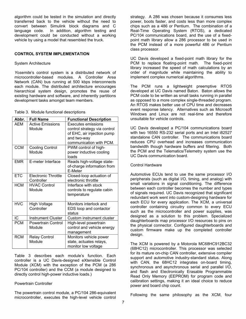
Table 3. Module functional descriptions
Abbr. Full Name Functional Description AEM Active Emissions
Module Executes emissions control strategy via control of EHC, air injection pump and two-way communication with PCM.
CCM Cooling Control Module
PWM control of high-power inductive cooling loads
EMR E-meter Interface Reads high-voltage state-of-charge information from E-Meter
ETC Electronic Throttle Controller
Closed-loop actuation of electronic throttle
HCM HVAC Control Module
Interface with stock controls to regulate cabin temperature
HVC High Voltage Controller
Monitors interlock and EDS loop and contactor status
IC Instrument Cluster Custom instrument cluster PCM Powertrain Control
Module High-level powertrain control and vehicle energy management
RCM Relay Control Module
Monitors vehicle power state, actuates relays, monitor low voltage
Table 3 describes each module’s function. Each controller is a UC Davis-designed eXtensible Control Module (XCM) with the exception of the PCM (a 286 PC/104 controller) and the CCM (a module designed to directly control high-power inductive loads.) Powertrain Controller
The powertrain control module, a PC/104 286-equivalent microcontroller, executes the high-level vehicle control
strategy. A 286 was chosen because it consumes less power, boots faster, and costs less than more complex chips such as a 486 or Pentium. The combination of a Real-Time Operating System (RTOS), a dedicated PC/104 communications board, and the use of a fixed-point math library allow a 286 processor to be used in the PCM instead of a more powerful 486 or Pentium class processor. UC Davis developed a fixed-point math library for the PCM to replace floating-point math. The fixed-point library increased the speed of math calculations by an order of magnitude while maintaining the ability to implement complex numerical algorithms. The PCM runs a lightweight preemptive RTOS developed at UC Davis named Baton. Baton allows the PCM code to be written as small tasks running in parallel as opposed to a more complex single-threaded program. An RTOS makes better use of CPU time and decreases event response latency. Alternatives such as Microsoft Windows and Linux are not real-time and therefore unsuitable for vehicle controls. UC Davis developed a PC/104 communications board with two 16550 RS-232 serial ports and an Intel i82527 standalone CAN controller. The communications board reduces CPU overhead and increases communication bandwidth though hardware buffers and filtering. Both the PCM and the Telematics/Telemetry system use the UC Davis communication board. Control Hardware Automotive ECUs tend to use the same processor I/O peripherals (such as digital I/O, timing, and analog) with small variations in signal conditioning. The difference between each controller becomes the number and types of signals required. UC Davis recognized that significant redundant work went into custom-designing hardware for each ECU for every application. The XCM, a universal controller containing circuitry common to every ECU such as the microcontroller and power supplies, was designed as a solution to this problem. Specialized daughterboards map processor I/O resources to pins on the physical connector. Configured daughterboards and custom firmware make up the completed controller design. The XCM is powered by a Motorola MC68HC912BC32 (68HC12) microcontroller. This processor was selected for its mature on-chip CAN controller, extensive compiler support and automotive industry-standard status. Along with CAN, the 68HC12 integrates on-board timing, synchronous and asynchronous serial and parallel I/O, and flash and Electronically Erasable Programmable Read Only Memory (EEPROM) for program code and calibration settings, making it an ideal choice to reduce power and board chip count. Following the same philosophy as the XCM, four
7
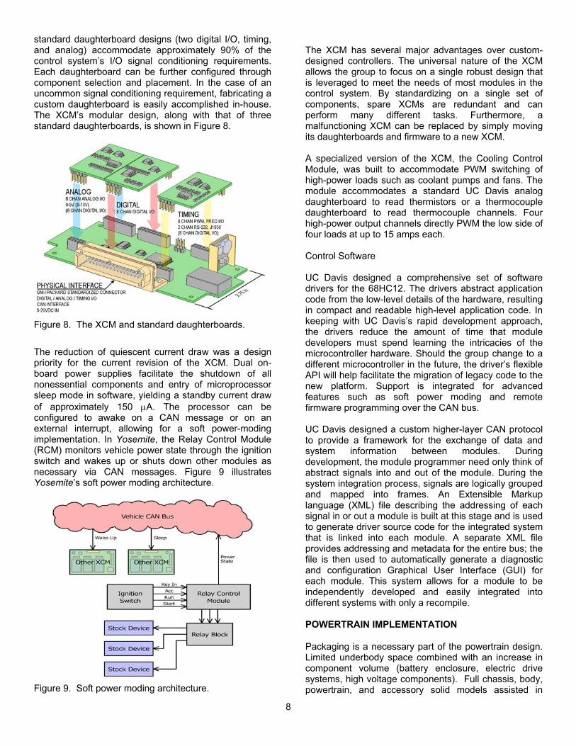
standard daughterboard designs (two digital I/O, timing, and analog) accommodate approximately 90% of the control system’s I/O signal conditioning requirements. Each daughterboard can be further configured through component selection and placement. In the case of an uncommon signal conditioning requirement, fabricating a custom daughterboard is easily accomplished in-house. The XCM’s modular design, along with that of three standard daughterboards, is shown in .
The XCM has several major advantages over custom-designed controllers. The universal nature of the XCM allows the group to focus on a single robust design that is leveraged to meet the needs of most modules in the control system. By standardizing on a single set of components, spare XCMs are redundant and can perform many different tasks. Furthermore, a malfunctioning XCM can be replaced by simply moving its daughterboards and firmware to a new XCM.
Figure 8
Figure 8. The XCM and standard daughterboards.
A specialized version of the XCM, the Cooling Control Module, was built to accommodate PWM switching of high-power loads such as coolant pumps and fans. The module accommodates a standard UC Davis analog daughterboard to read thermistors or a thermocouple daughterboard to read thermocouple channels. Four high-power output channels directly PWM the low side of four loads at up to 15 amps each. Control Software UC Davis designed a comprehensive set of software drivers for the 68HC12. The drivers abstract application code from the low-level details of the hardware, resulting in compact and readable high-level application code. In keeping with UC Davis’s rapid development approach, the drivers reduce the amount of time that module developers must spend learning the intricacies of the microcontroller hardware. Should the group change to a different microcontroller in the future, the driver’s flexible API will help facilitate the migration of legacy code to the new platform. Support is integrated for advanced features such as soft power moding and remote firmware programming over the CAN bus.
The reduction of quiescent current draw was a design priority for the current revision of the XCM. Dual on-board power supplies facilitate the shutdown of all nonessential components and entry of microprocessor sleep mode in software, yielding a standby current draw of approximately 150 µA. The processor can be configured to awake on a CAN message or on an external interrupt, allowing for a soft power-moding implementation. In Yosemite, the Relay Control Module (RCM) monitors vehicle power state through the ignition switch and wakes up or shuts down other modules as necessary via CAN messages. Figure 9 illustrates Yosemite’s soft power moding architecture.
UC Davis designed a custom higher-layer CAN protocol to provide a framework for the exchange of data and system information between modules. During development, the module programmer need only think of abstract signals into and out of the module. During the system integration process, signals are logically grouped and mapped into frames. An Extensible Markup language (XML) file describing the addressing of each signal in or out a module is built at this stage and is used to generate driver source code for the integrated system that is linked into each module. A separate XML file provides addressing and metadata for the entire bus; the file is then used to automatically generate a diagnostic and configuration Graphical User Interface (GUI) for each module. This system allows for a module to be independently developed and easily integrated into different systems with only a recompile.
POWERTRAIN IMPLEMENTATION
Packaging is a necessary part of the powertrain design. Limited underbody space combined with an increase in component volume (battery enclosure, electric drive systems, high voltage components). Full chassis, body, powertrain, and accessory solid models assisted in Figure 9. Soft power moding architecture.
8

packaging and allowed for iterative packaging design for cooling, wiring, weight distribution, and ease of repair. Rear Wheel Powertrain The rear wheels are driven by a 1.9L DOHC Saturn engine and a 75kW UQM SR218H brushless permanent magnet electric motor. The total rear powertrain output is 167kW (223hp) at 6000rpm and a maximum rear axle torque of 6669N-m (4918lb-ft) at 2500rpm in first gear. Design of the powertrain housing is based on a force and moment analysis of the powertrain under peak torque loading. shows the configuration of the primary powertrain. The UQM drive motor does not have a structural case, requiring a motor housing to isolate the UQM motor from the reaction torque of the ICE. The housing, or torque tube, joins with the electric motor plate, which is connected to the transmission by the clutch housing. Plates were manufactured for the ICE, motor, and transmission to accommodate the different component bolt patterns. The housings and plates were manufactured from 6061-T6 aluminum and the shaft and flange out of hardened 4140 chrome-moly steel.
Figure 10
Figure 10. Primary powertrain diagram.
To insure the rigidity of the assembled powertrain, a static analysis was performed with the powertrain treated as a simply supported beam. The analysis yielded the shear forces and bending moments throughout. These values were then used to analyze solid models, drawn in Inventor, and then transferred to CosmosWorks, a finite element analysis (FEA) package. The results are given in Table 4. Space constraints dictated that the rear wheel powertrain be placed as high in the vehicle as possible. This was accomplished by designing the transmission bell housing to be as small as possible and modifying the transmission tunnel. To make the bell housing small meant finding a small clutch. A Tilton 5.5 inch two-plate
clutch was selected. This raised the rear wheel powertrain enough to fit the front wheel powertrain underneath it.
Table 4. Primary Powertrain Design Results
Component Factor of Safety for Yield Torque Tube 3.5 Clutch Housing 6.2 Trans. Mounting Plate 5.3 EM Mounting Plate 5.8 ICE Mounting Plate 14 ICE Coupling Shaft 2.7 EM Flywheel Flange 12
FUEL SYSTEM
A flexible fuel system was designed with highly corrosion resistant materials for compatibility with E85. Materials were chosen from a list published by the American Automobile Manufactures Association as suitable for E85 usage. The fuel flow rate of E85 was calculated to match with RFG by comparing their lower heating values (LHV). The LHV of E85 22.6 MJ/L was 28% lower than RFG’s 31.5MJ/L. The following equation verifies the increase in static flow needed to compensate for the LHV of E85. The increase in static flow for E85 is:
%5.4510
7/14185
1/
/85 =−=−=
FratioA
FratioAE E
RFGν
The formulas below describe how adjusting the amount of fuel injected by the A/F ratio results in identical amounts of energy injected. Gasoline: ( ) ( ) MJLMJLEinjected 0.330.331 =∗=
E85: ( ) ( ) MJLMJLEinjected 0.336.22455.1 =∗= The capacity of the stock injectors (176cc/min Delphi units) needed to be increased to 256cc/min at 43 psig to maintain engine power output. Instead of using 256cc/min injectors at 43 psig, smaller 225cc/min injectors were used at a higher pressure (50 psig) to improve the atomization of the E85. Fuel System Hardware Materials resistant to ethanol corrosion were chosen for Yosemite’s design. Earls -6 Army-Navy (AN) Prolite hose couple the hard lines with the fuel tank and fuel rail interfaces. Anodized –6AN fittings replaced the plastic push-on connectors. 3/8” stainless steel hard line runs down the passenger side frame rail to deliver fuel from the tank to the regulator and return excess fuel back to the tank. A high flow stainless mesh fuel filter precedes a 36 GPH alcohol compatible gerotor style fuel pump
9

mounted on the rear passenger side frame rail. Ideally, an intake fuel pump would be used, however an external pump was chosen for easy removal of the tank. A bypass pressure regulator mounted in the engine bay regulates 50psig of fuel to the fuel rail while the excess is returned to the surge tank inside the main tank. An eight-gallon custom tank with internal baffles and surge tank was designed to be easily removed for weighing. Zero-loss Viton quick disconnects facilitate easy removal and decrease spillage. The stock Ford Explorer evaporative emissions system was adapted to the Saturn 1.9L engine purge system. The purge solenoid located over the rear differential was piggybacked onto the Saturn purge circuit. Fuel Tank The new tank sits between the frame rails, aft of the rear differential under the rear of the truck. The tank wraps around the spare utilizing otherwise wasted space. This arrangement does not compromise rear crush zone and does not hinder the removal of the spare tire. The stainless steel fuel tank was fabricated and tested by, a professional machine shop. T-304 stainless steel was chosen for corrosion resistance and ease of fabrication. Alternatives, such as anodized aluminum and rota-modeled polyethylene, were tested with limited success. An aircraft-style flush fill plate from British American Transfer seals the inlet. Earls® bulkhead fittings and rollover vent were fitted to the tank for fuel supply, fuel return and the vent. Zero loss quick-connects with Viton seals and Army-Navy ends were used to facilitate quick removal. Internal baffles prevent fuel pump starvation and reduce fuel slosh. ELECTRONIC THROTTLE CONTROL
A conventional vehicle produces a significant portion of its emissions during transient operation. Yosemite’s electronic ICE throttle is decoupled from the accelerator pedal. The PCM uses the ICE to maintain the steady-state load, while using the EM to handle transient demands. The results of this system are a cleaner, more efficient vehicle. The throttle-by-wire system shown in is used to implement this system consisted of a Visteon Electronic Throttle Body (ETB) driven by high power electronics controlled by the Electronic Throttle Control (ETC).
Figure 11
Figure 11. Electronic throttle controller
EMISSIONS CONTROL
An effective emissions control strategy must focus on the entire powertrain system. Looking at single components can help in the reduction of pollutants and Greenhouse gasses, but the overall performance of the vehicle depends on how those components interact. Meeting the SULEV emissions target requires an advanced aftertreatment system as well as precise engine control and tuning. In the stock vehicle the production 2001 Saturn 1.9L engine with California emissions systems meets the LEV target. Using the same engine in a vehicle considerably larger can have impacts if not carefully controlled and tested. In an effort to meet SULEV emissions standards for P-ZEV credit, Yosemite uses engine control, a close-coupled catalyst, air injection pump, and an electrically heated catalyst (EHC). The EHC is a 1200 cell count catalyst with a .004 mm wall thickness. The low thermal mass of this design provides a faster warm-up and a high surface area for improved gas interaction5,6. The catalyst will reach light-off temperature in about 30 seconds. When the vehicle reaches engine turn-on speed, the Active Emissions Module (AEM) checks the temperature of the catalyst and fires the EHC if the temperature is below light-off. After the EHC has reached light-off temperature the AEM signals the PCM that the operating temperature for EHC has been reached, at which point the PCM allows the engine to start.
In the event of power failure to the ETB, double return springs ensure that the throttle closes. In the event of communication failure between the ECM and the PCM, the ETC goes into a fail-safe mode, which cuts fuel injection and closes the throttle.
Figure 12 depicts the benefits of using an EHC in a conventional manner and the possibilities of improvement possible with pre-heating the catalyst, shown by the new axis point where the engine would now start.
10

Figure 12. Accumulated emissions comparison7.
The aftertreatment effects of the system are best described by Figure 13. Preliminary comparison testing between E-85 and California RFG resulted in a decrease of regulated and GHG emissions.
Figure 13. Modal emissions reduction8.
0
20
40
60
80
100
120
CO2 CO HC O2 NO
Perc
enta
ge C
ompa
ired
to R
FG (%
) RFG E85
Figure 14. RFG vs. E85 emissions test data. Ethanol is an oxygenate and aids in the combustion process resulting in a higher combustion efficiency and lower GHG index. In determining the GHG index CO2, CH4, and N2O are measured and weighed with their
relative impact to the environment.
GHGI = CO2 + 21*CH4 + 310*N2O
N2O generation occurs at low catalytic temperatures starting at 150°C, peaking around 200°C and continuing to 400°C in the catalyst resulting from a combination of NOx and CO9. Operating at temperatures above this region in the catalyst produces very few N2O emissions, by heating the catalyst to light off before the engine starts we avoid most of this high GHG producing region. Reduction of CO2 is dependent on the power necessary, but pre-warming the EHC can provide a hot catalyst at engine start up allowing for a significant reduction of CH4 and N2O resulting in a lower GHGI rating for Yosemite.
TRACTION BATTERY
Selection and integration of the traction battery is important in maximizing the efficiency, emissions characteristics, and cycle life of an HEV. The batteries must have a high specific energy to provide adequate storage for a significant all-electric range. A high specific power is required for maximum recovery of regenerative braking energy and full power accelerations. A high energy density minimizes packaging and weight requirements. Additionally, the traction battery should have a high cycle life and be maintenance free for increased consumer value. Battery Selection A Nickel Metal Hydride (NiMH) battery pack from Ovonic Battery Company was selected because of its high energy and power density characteristics, as well as its sealed cell design, illustrated in Figure 15. The battery pack consists of 24 modules of 50 Ahr batteries. The nominal voltage is 317V.
Figure 15. Ovonic NiMH battery cell10.
This specific NiMH chemistry demonstrates up to 750 Watts per kg (W/kg) of peak power density. These high power batteries are extremely efficient, and are capable
11
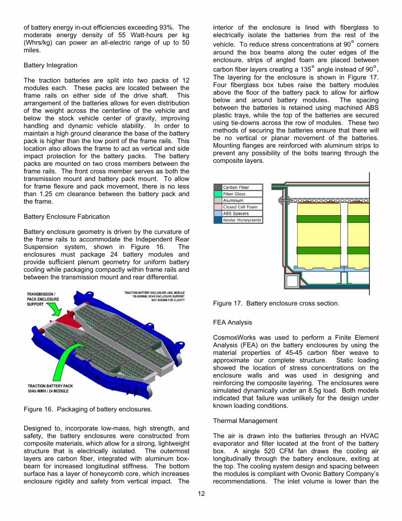
of battery energy in-out efficiencies exceeding 93%. The moderate energy density of 55 Watt-hours per kg (Whrs/kg) can power an all-electric range of up to 50 miles. Battery Integration The traction batteries are split into two packs of 12 modules each. These packs are located between the frame rails on either side of the drive shaft. This arrangement of the batteries allows for even distribution of the weight across the centerline of the vehicle and below the stock vehicle center of gravity, improving handling and dynamic vehicle stability. In order to maintain a high ground clearance the base of the battery pack is higher than the low point of the frame rails. This location also allows the frame to act as vertical and side impact protection for the battery packs. The battery packs are mounted on two cross members between the frame rails. The front cross member serves as both the transmission mount and battery pack mount. To allow for frame flexure and pack movement, there is no less than 1.25 cm clearance between the battery pack and the frame. Battery Enclosure Fabrication Battery enclosure geometry is driven by the curvature of the frame rails to accommodate the Independent Rear Suspension system, shown in . The enclosures must package 24 battery modules and provide sufficient plenum geometry for uniform battery cooling while packaging compactly within frame rails and between the transmission mount and rear differential.
Figure 16
Figure 16. Packaging of battery enclosures.
Designed to, incorporate low-mass, high strength, and safety, the battery enclosures were constructed from composite materials, which allow for a strong, lightweight structure that is electrically isolated. The outermost layers are carbon fiber, integrated with aluminum box-beam for increased longitudinal stiffness. The bottom surface has a layer of honeycomb core, which increases enclosure rigidity and safety from vertical impact. The
interior of the enclosure is lined with fiberglass to electrically isolate the batteries from the rest of the vehicle. To reduce stress concentrations at 90° corners around the box beams along the outer edges of the enclosure, strips of angled foam are placed between carbon fiber layers creating a 135° angle instead of 90°. The layering for the enclosure is shown in Figure 17. Four fiberglass box tubes raise the battery modules above the floor of the battery pack to allow for airflow below and around battery modules. The spacing between the batteries is retained using machined ABS plastic trays, while the top of the batteries are secured using tie-downs across the row of modules. These two methods of securing the batteries ensure that there will be no vertical or planar movement of the batteries. Mounting flanges are reinforced with aluminum strips to prevent any possibility of the bolts tearing through the composite layers.
Figure 17. Battery enclosure cross section.
FEA Analysis CosmosWorks was used to perform a Finite Element Analysis (FEA) on the battery enclosures by using the material properties of 45-45 carbon fiber weave to approximate our complete structure. Static loading showed the location of stress concentrations on the enclosure walls and was used in designing and reinforcing the composite layering. The enclosures were simulated dynamically under an 8.5g load. Both models indicated that failure was unlikely for the design under known loading conditions. Thermal Management The air is drawn into the batteries through an HVAC evaporator and filter located at the front of the battery box. A single 520 CFM fan draws the cooling air longitudinally through the battery enclosure, exiting at the top. The cooling system design and spacing between the modules is compliant with Ovonic Battery Company’s recommendations. The inlet volume is lower than the
12

exit volume so that the pressure drop is constant through the length of the enclosure. Airflow is monitored and controlled by Enova’s Battery Care Unit (BCU), which also provides real-time data on temperature and voltage from each module. This information is transmitted to the CCM and used to control the battery cooling fan speed. At high temperatures, the HVAC system will actively cool the intake air. In the case of continued temperature increases, the PCM will limit battery current to prevent battery pack damage.
Climate Control System The HVAC system is the largest accessory load. Electric AC systems have proven to be more efficient than engine-driven systems12. The stock mechanical AC compressor was replaced by a Sanden electric compressor. The Sanden system is a scroll compressor with a 600-7800 RPM speed range, a 33 cc displacement and an inverter operating at 320 VDC. An electric compressor is more flexible as it is not engine driven and provides full cooling at any engine speed.
Battery Charging The compressor housing is an integrated
motor/compressor assembly, which reduces risk of refrigerant leakage compared to a conventional system. The powerful 4kW DC brushless motor has a cooling capacity of approximately 6 kW (20,000 BTU/hour).
The Enova drive system also contains a 6.6 kW conductive charger. This charger is capable of charging the battery from 10% (minimum SOC) to 100% SOC in 2.4 hours from a 240V outlet and 10.2 hours from a 120V outlet. The lower voltage option reduces home infrastructure costs and provides for more convenient charging sites, as an electrical plug and cord are all that is needed.
The HVAC Control Module (HCM) receives the A/C request signal from the stock HVAC interface. It controls the compressor speed based on cabin temperature and vehicle speed. This allows an accurate temperature adjustment and a better power consumption control.
ACCESSORY SYSTEMS
Instrument Cluster Power Steering The stock instrument cluster (IC) was intended for a conventional vehicle and does not communicate information about hybrid vehicle operations to the driver without significant modification. A new instrument panel was designed to simplify physical and electrical integration and better reflect the hybrid vehicle systems information while enhancing driver awareness. The instrument cluster design fully complies with Federal Motor Vehicle Safety Standards sections 101 and 102.11
A high-voltage electric power steering unit from a GM Electric S-10 replaces the engine-driven stock unit. The electric power steering unit adjusts fluid pressure according to steering angle rate of change and vehicle speed. The stock rack-and-pinion steering is maintained without modification. Telematics Service Framework
Automotive telematics systems currently face a chicken-or-egg problem. Lackluster consumer demand has yet to stimulate the development of serious telematics platforms. Consumer demand is driven by the availability (or lack thereof) of useful and innovative telematics applications. Completing the cycle, the development of new telematics applications – the so called “killer app” – requires the availability of a suitable platform. The risk of being locked into a closed system reduces the attractiveness of currently-available telematics systems.
Integration of the new instrument panel was simplified by using the stock IC housing and designing a new graphic overlay with the same dimensions. The new IC design incorporates programmable stepper-motor modules, which provide a high-level software interface to each gauge on the instrument panel. Electro-luminescent material is used for the backlight, saving power over traditional incandescent backlighting. Only five electrical signals are needed to provide the necessary information to the IC, greatly reducing wiring complexity. Information that would have been provided by the SCP and UBP networks are now provided by the CAN bus.
To counteract this problem, the UC Davis objective is to develop a telematics framework specification that decouples the platform (vehicle) from the applications (services), allowing telematics services to be deployed to vehicles already in the field. Other telematics systems manufacturers may choose to make their vehicles comply with the framework, eventually resulting in a critical mass of deployed vehicles. An open platform with a large (and growing) base of deployed vehicles will attract independent telematics service developers. Eventually, this environment will foster the development of the one or more “killer apps” as services running on the UC Davis framework.
The new dashboard includes an innovative power meter to give the driver an immediate and intuitive 'feel' for power flow in the vehicle. More comprehensive vehicle information is available on an integrated dot-matrix vacuum-fluorescent display (VFD). The VFD provides a flexible display capable of several functions including a trip computer, driving style, navigational cues, and powertrain energy flow. Three buttons on the steering wheel scroll through the display screens. Critical indicators for system faults and safety problems override the default displays when necessary. The UC Davis Telematics Service Framework (TSF) is a
13

specification for a set of Java services running on an Open Services Gateway Initiative (OSGi)-compliant framework. The standard Java interfaces specified by the TSF expose vehicle systems to dynamically-loaded telematics services. TSF services can access vehicle services representing the powertrain, electrical systems, body electronics, and Human Machine Interfaces (HMI). Services may choose to interact with the driver through a graphical touch-screen interface or through a voice interface. Yosemite is equipped with prototype implementations of both interfaces. Examples of telematics services that could be easily developed and deployed to platform-compliant vehicles include: real-time collection and dissemination of traffic data, intelligent traffic-aware navigation and routing, vehicle-to-grid charge/discharge control, or remote vehicle control and monitoring. Telematics System Implementation The core of the telematics system, illustrated in
, is a Pentium-class PC/104 computer running Linux. This application computer runs a standard OSGi framework implementation on top of a Java virtual machine. A 7.2” transflective (part reflective, part transmissive) Liquid Crystal Display (LCD) panel replaces the vehicle’s stock radio, providing a crisp backlit display in low-light situations while retaining excellent readability in bright sunlight. A Surface Acoustic Wave (SAW) touch screen overlays the LCD panel, providing a tactile interface without the "filmy" or "plastic" feel common to resistive touch screens. A soft-key user interface ensures safe operation by the driver. Complex user interfaces are only available when the vehicle is not in motion. A voice interface provides access to basic functionality without taking the driver’s attention from the road. Dynamically-loaded telematics services may elect to use the visual/tactile interface, the voice interface, or both.
Figure 18
Figure 18. Telematics system architecture.
A PC/104 Cisco router provides network connectivity to the outside world via 802.11b where coverage exists and a low-speed Cellular Digital Packet Data (CDPD) cellular data modem in areas without 802.11b. A Trimble Lassen SKII embedded GPS module provides National Marine Electronics Association (NMEA) positioning data to the router. Either the telematics computer or remote systems can then access the NMEA stream via TCP/IP. The telematics system interacts with the vehicle’s CAN control network using a PC/104 CAN/RS-232 card designed and built by UC Davis. The telematics system runs a Java CAN Hardware Abstraction Layer and an object-oriented implementation of the UC Davis higher-layer protocol. Audio and visual entertainment is provided by modules on a 25 Mbps fiber optic Media Oriented System Transport (MOST) bus. The telematics display includes virtual user interfaces for each multimedia component –
for example, a radio tuning screen and a CD player
control screen. The MOST bus allows for seamless expandability and easy routing of any source to any endpoint. Yosemite includes a single AM/FM tuner module, a single audio/video CD player, and a single audio interface connected to the stock audio system. The consumer could easily add additional devices and listening stations to the system in the field. Cameras behind each rear view mirror and under the rear bumper cover the driver’s blind spots. Images are displayed on a small LCD screen embedded in the rear view mirror. When the left or right turn signals are engaged or the vehicle is shifted into reverse, the appropriate camera is selected and the display turns on. At all other times, the display is off. The camera selection may be manually overridden through the telematics interface. DFMEA
The results of the Design Failure Mode and Effects Analysis (DFMEA) performed on Yosemite are presented in Appendix B. DFMEA is used to address potential design flaws, rather than failures due to problems introduced after the design phase. Risk assessment factors were assigned to potential failures based on three criteria: likelihood of detection by design control (D), severity of effect (S), and probability of occurrence (O). The R, S, and O values were multiplied to create the Risk Priority Number (RPN). Items with RPN values higher than 75 are deemed at risk for failure and require action.
14

MANUFACTURABILITY AND COST POTENTIAL
Cost Analysis There are many difficulties inherent to a cost analysis of an advanced vehicle design. Validated component cost data is nearly always proprietary in nature. Two significant efforts to understand and develop cost models for advanced vehicles were undertaken by Cuenca et al13 and Graham, et al14. The steps for developing cost models include:
1. Determine conventional powertrain component costs.
2. Develop cost relationships for advanced system components.
3. Finalize vehicle glider cost (vehicle price without powertrain.)
4. Include cost optimization in the vehicle design process.
5. Calculate projected list price of advanced vehicle design.
This cost model, in 2002 dollars, assumes a production volume of roughly 100,000 vehicles. Figure 19 shows the component price relationships for engines, transmissions, and electric drive systems used in the conventional and hybrid Explorer. Subtracting the costs of the deleted conventional components results in an estimated glider list price of $21,933. Adding the hybrid drive components featured in Yosemite and the telematics system raises the final predicted list price of the vehicle to $40,772.
$0
$500
$1,000
$1,500
$2,000
$2,500
0 20 40 60 80 100 120 140
Component Power (kW)
Com
pone
nt C
ost
V6 Engine
L4 Engine
DC Electric Motor
E/M Controller
Figure 19. Component cost relationships. The cost formulae for these components are basic linear approximations. The added components are then marked up by a factor of 1.5 to 2.0 to arrive at the simulated list price. The battery cost assumption used for this model was
$280 per kWhr of energy storage. Recent aggressive development in the field of advanced batteries indicates that this may be a reasonable cost estimate. Panasonic EV Energy Co. recently announced plans to lower the cost of high-power NiMH batteries to $300 per kWhr by 200515. The NiMH chemistry used in Yosemite has a higher energy density, which lowers the battery cost. In addition, the current state of the laptop battery market shows that Lithium-Ion technology is currently available at $320 per kWhr16.
Table 5. Cost breakdown of stock and hybrid Explorer
Stock XLT Yosemite HEVExplorer XLT Glider $ 21,933 $ 21,933 Engine $ 5,904 $ 3,524 Transmission $ 2,400 $ 1,500 Transfer Case $ 1,200 $ 0 Accessory Power $ 488 $ 608 Electric Traction $ 100 $ 4,900 Energy Storage System $ 60 $ 6,617 Vehicle Charging System $ 0 $ 690 Telematics System $ 0 $ 1000 Total Vehicle List Price $32,085 $40,772 Manufacturing Issues and Potential Yosemite is intended for production on a standard U152 production line. The advanced hybrid drive systems are designed to replace existing powertrain components with similar packaging and mounting requirements. The design layout of the vehicle does not impact interior cabin volume or compromise the vehicle structure in any way. There are a number of important manufacturing issues that govern the introduction and market potential of hybrid electric vehicles. Crucial issues include the cost and longevity of advanced battery chemistries and the cost of high-power electric drive systems. Component manufacturers are working hard to reduce the cost of these advanced systems. Assuming that the current Yosemite vehicle is a two-year research and development project, it would proceed to an attribute prototype phase in 2004 (prototypes made with production components and materials). A production vehicle could be ready for sale in 2006 at an estimated list price of $40,772. Intended Market The UC Davis Yosemite is a premium sport-utility vehicle. Its buyers will demand class-leading power and performance, but will also appreciate the strong environmental statement made by the vehicle. Many of the first buyers will be technological early adopters intrigued by the hybrid drive system, dual use of
15
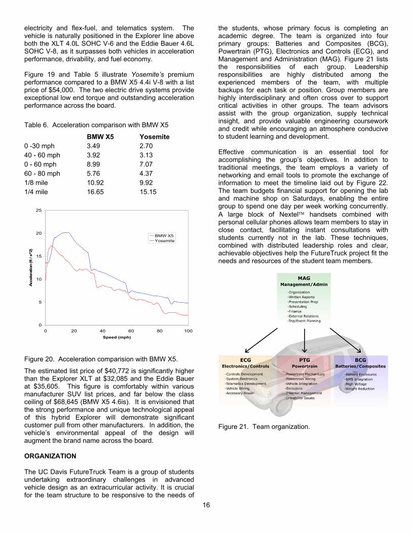
electricity and flex-fuel, and telematics system. The vehicle is naturally positioned in the Explorer line above both the XLT 4.0L SOHC V-6 and the Eddie Bauer 4.6L SOHC V-8, as it surpasses both vehicles in acceleration performance, drivability, and fuel economy. Figure 19 and Table 5 illustrate Yosemite’s premium performance compared to a BMW X5 4.4i V-8 with a list price of $54,000. The two electric drive systems provide exceptional low end torque and outstanding acceleration performance across the board.
Table 6. Acceleration comparison with BMW X5
BMW X5 Yosemite 0 -30 mph 3.49 2.70 40 - 60 mph 3.92 3.13 0 - 60 mph 8.99 7.07 60 - 80 mph 5.76 4.37 1/8 mile 10.92 9.92 1/4 mile 16.65 15.15
0
5
10
15
20
25
0 20 40 60 80 1Speed (mph)
Acc
eler
atio
n (ft
/ s
2)
00
BMW X5Yosemite
Figure 20. Acceleration comparision with BMW X5.
The estimated list price of $40,772 is significantly higher than the Explorer XLT at $32,085 and the Eddie Bauer at $35,605. This figure is comfortably within various manufacturer SUV list prices, and far below the class ceiling of $68,645 (BMW X5 4.6is). It is envisioned that the strong performance and unique technological appeal of this hybrid Explorer will demonstrate significant customer pull from other manufacturers. In addition, the vehicle’s environmental appeal of the design will augment the brand name across the board. ORGANIZATION
The UC Davis FutureTruck Team is a group of students undertaking extraordinary challenges in advanced vehicle design as an extracurricular activity. It is crucial for the team structure to be responsive to the needs of
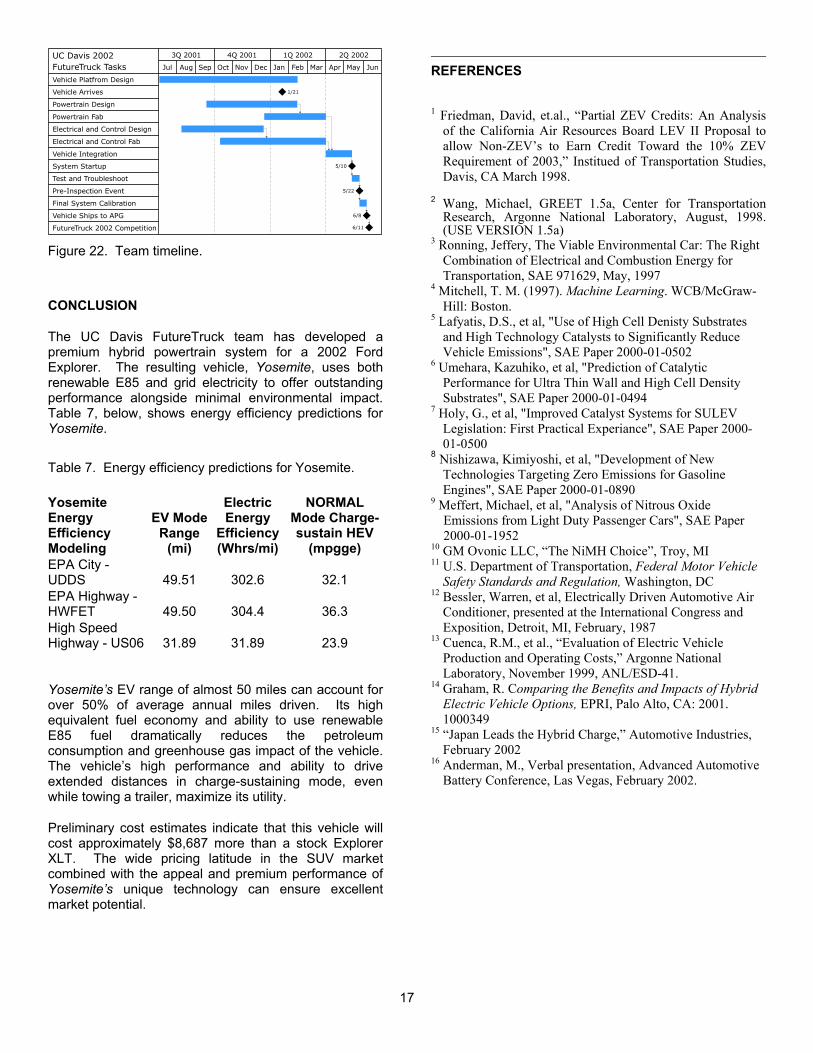
the students, whose primary focus is completing an academic degree. The team is organized into four primary groups: Batteries and Composites (BCG), Powertrain (PTG), Electronics and Controls (ECG), and Management and Administration (MAG). Figure 21 lists the responsibilities of each group. Leadership responsibilities are highly distributed among the experienced members of the team, with multiple backups for each task or position. Group members are highly interdisciplinary and often cross over to support critical activities in other groups. The team advisors assist with the group organization, supply technical insight, and provide valuable engineering coursework and credit while encouraging an atmosphere conducive to student learning and development. Effective communication is an essential tool for accomplishing the group’s objectives. In addition to traditional meetings, the team employs a variety of networking and email tools to promote the exchange of information to meet the timeline laid out by Figure 22. The team budgets financial support for opening the lab and machine shop on Saturdays, enabling the entire group to spend one day per week working concurrently. A large block of Nextel handsets combined with personal cellular phones allows team members to stay in close contact, facilitating instant consultations with students currently not in the lab. These techniques, combined with distributed leadership roles and clear, achievable objectives help the FutureTruck project fit the needs and resources of the student team members.
Figure 21. Team organization.
16
3Q 2001 4Q 2001 1Q 2002 2Q 2002
Jul Aug Sep Oct Nov Dec Jan Feb Mar Apr May Jun
UC Davis 2002FutureTruck Tasks Vehicle Platfrom Design
Test and Troubleshoot
Pre-Inspection Event
Final System Calibration
Vehicle Ships to APG
FutureTruck 2002 Competition
Powertrain Design
Powertrain Fab
Electrical and Control Design
Electrical and Control Fab
Vehicle Integration
System Startup
Vehicle Arrives
5/22
6/11
6/8
5/10
1/21
REFERENCES
1 Friedman, David, et.al., “Partial ZEV Credits: An Analysis of the California Air Resources Board LEV II Proposal to allow Non-ZEV’s to Earn Credit Toward the 10% ZEV Requirement of 2003,” Institued of Transportation Studies, Davis, CA March 1998.
2 Wang, Michael, GREET 1.5a, Center for Transportation
Research, Argonne National Laboratory, August, 1998. (USE VERSION 1.5a)
3 Ronning, Jeffery, The Viable Environmental Car: The Right Combination of Electrical and Combustion Energy for Transportation, SAE 971629, May, 1997
Figure 22. Team timeline.
4 Mitchell, T. M. (1997). Machine Learning. WCB/McGraw-
Hill: Boston. CONCLUSION 5 Lafyatis, D.S., et al, "Use of High Cell Denisty Substrates
and High Technology Catalysts to Significantly Reduce Vehicle Emissions", SAE Paper 2000-01-0502
The UC Davis FutureTruck team has developed a premium hybrid powertrain system for a 2002 Ford Explorer. The resulting vehicle, Yosemite, uses both renewable E85 and grid electricity to offer outstanding performance alongside minimal environmental impact. Table 7, below, shows energy efficiency predictions for Yosemite.
6 Umehara, Kazuhiko, et al, "Prediction of Catalytic Performance for Ultra Thin Wall and High Cell Density Substrates", SAE Paper 2000-01-0494
7 Holy, G., et al, "Improved Catalyst Systems for SULEV Legislation: First Practical Experiance", SAE Paper 2000-01-0500
8 Nishizawa, Kimiyoshi, et al, "Development of New Technologies Targeting Zero Emissions for Gasoline Engines", SAE Paper 2000-01-0890
Table 7. Energy efficiency predictions for Yosemite.
Yosemite Energy Efficiency Modeling
EV Mode Range
(mi)
Electric Energy
Efficiency (Whrs/mi)
NORMAL Mode Charge-sustain HEV
(mpgge) EPA City - UDDS 49.51 302.6 32.1 EPA Highway - HWFET 49.50 304.4 36.3 High Speed Highway - US06 31.89 31.89 23.9
9 Meffert, Michael, et al, "Analysis of Nitrous Oxide Emissions from Light Duty Passenger Cars", SAE Paper 2000-01-1952
10 GM Ovonic LLC, “The NiMH Choice”, Troy, MI 11 U.S. Department of Transportation, Federal Motor Vehicle
Safety Standards and Regulation, Washington, DC 12 Bessler, Warren, et al, Electrically Driven Automotive Air
Conditioner, presented at the International Congress and Exposition, Detroit, MI, February, 1987
13 Cuenca, R.M., et al., “Evaluation of Electric Vehicle Production and Operating Costs,” Argonne National Laboratory, November 1999, ANL/ESD-41.
14 Graham, R. Comparing the Benefits and Impacts of Hybrid Electric Vehicle Options, EPRI, Palo Alto, CA: 2001. 1000349
Yosemite’s EV range of almost 50 miles can account for over 50% of average annual miles driven. Its high equivalent fuel economy and ability to use renewable E85 fuel dramatically reduces the petroleum consumption and greenhouse gas impact of the vehicle. The vehicle’s high performance and ability to drive extended distances in charge-sustaining mode, even while towing a trailer, maximize its utility.
15 “Japan Leads the Hybrid Charge,” Automotive Industries, February 2002
16 Anderman, M., Verbal presentation, Advanced Automotive Battery Conference, Las Vegas, February 2002.
Preliminary cost estimates indicate that this vehicle will cost approximately $8,687 more than a stock Explorer XLT. The wide pricing latitude in the SUV market combined with the appeal and premium performance of Yosemite’s unique technology can ensure excellent market potential.
17

APPENDIX A Finite Element Analysis: Factor of Safety results
APPENDIX B Table of DFMEA results
Item S D O RPN
Potential Failure Mode
Potential Effects of Failure
Potential Causes/ Mechanisms of Failure
Current Design Controls Actions
Engine 8 2 2 32
-Overheat -Blown head gasket
-Warp head
-Engine failure
-Incorrect heat production of engine
-Incorrect heat rejection of radiator
-Design review -Experiments -Robust design -Worst case analysis
-
Engine Coupling
Shaft 8 3 3 72
-Over-torque Fracture of shaft
-Engine non-op -Lower Grade Material -Neglected Dynamic effects
-Robust design -FEA -Design review
-Make multiple backups
-Simplify replacement
Battery System 9 3 3 81
-Overheat -Thermal runaway
-Breech of Enclosure
-Battery damage -Decreased
capacity -Fire
-Underestimated pressure drop in cooling airflow
-Robust design -Experiments -Design review
-Implement a secondary cooling circuit -Improve vehicle isolation -Simplify enclosure replacement
Powertrain Mounting 10 2 3 60
-Mount tear -Bracket failure
-Powertrain non-op -Transmission
damage
-Incorrect stress calculations -Lower grade component -Neglected dynamic effects
-Robust design -Design review -
High Voltage Wiring
10 2 5 100 -Ground fault -Short
-Shock -HV electrical non-op -Fire
-Incorrect insulation grade -Improper insulation of conductive surfaces
-Inadequate abrasion resistance
-Robust design -MegaOhm-meter testing
-Fuses -Ground fault detection
-Interlock loop
-Make multiple backups -Implement testing nodes for MegaOhm -Simplify schematic documentation
Powertrain Housing 8 2 2 32
-Crack propagation from openings
-Vehicle non-op -Engine damage -Motor damage -High voltage short
-Neglected dynamic effects -Robust design -FEA -Design review
-