design and development of compact pulse forming...
TRANSCRIPT
Special Issue | October 2014 97
BARC NEWSLETTERFounder’s DayDESIGN AND DEVELOPMENT OF COMPACT
PULSE FORMING LINES
Surender Kumar Sharma & Anurag ShyamE&ED
Abstract
Pulse forming line (PFL) is an important subsystem of pulsed power system for shaping and delivering fast pulses to
the load. PFLs with higher dielectric constant ceramics materials and alternative engineering topologies are designed
and developed to reduce its size. A novel technique is also proposed using the transmission line characteristics of
the PFL to generate fast repetitive double pulse (~ 100 ns) with very short (~ 30 ns) inter pulse repetition interval.
Keywords: Pulsed Power, PFL, Ceramic, Helical
Dr. Surender Kumar Sharma is the recipient of the DAE Young Engineer Award for the year 2012
Introduction
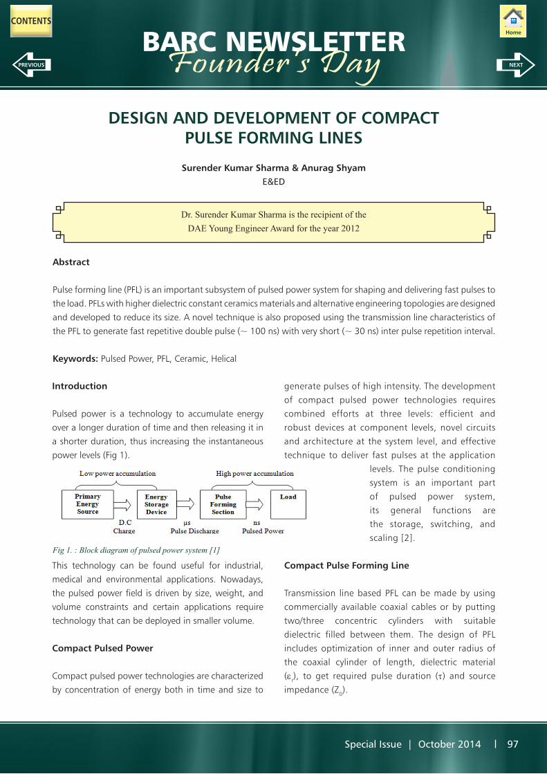
Pulsed power is a technology to accumulate energy
over a longer duration of time and then releasing it in
a shorter duration, thus increasing the instantaneous
power levels (Fig 1).
This technology can be found useful for industrial,
medical and environmental applications. Nowadays,
the pulsed power field is driven by size, weight, and
volume constraints and certain applications require
technology that can be deployed in smaller volume.
Compact Pulsed Power
Compact pulsed power technologies are characterized
by concentration of energy both in time and size to
generate pulses of high intensity. The development
of compact pulsed power technologies requires
combined efforts at three levels: efficient and
robust devices at component levels, novel circuits
and architecture at the system level, and effective
technique to deliver fast pulses at the application
levels. The pulse conditioning
system is an important part
of pulsed power system,
its general functions are
the storage, switching, and
scaling [2].
Compact Pulse Forming Line
Transmission line based PFL can be made by using
commercially available coaxial cables or by putting
two/three concentric cylinders with suitable
dielectric filled between them. The design of PFL
includes optimization of inner and outer radius of
the coaxial cylinder of length, dielectric material
(er), to get required pulse duration (t) and source
impedance (Z0).
Fig 1. : Block diagram of pulsed power system [1]
Home
NEXTPREVIOUS ê ê
CONTENTS

98 Special Issue | October 2014
BARC NEWSLETTERFounder’s DayDevelopment of Solid dielectric PFL using ceramic material
The length of the PFL is, L ~ 1/e1/2. The higher e can
lead to shorter length of the PFL. The ceramic material
has large dielectric constant (> 100) and is ideal for
energy storage in PFL. Barium Titanate ceramic was
not widely used in pulsed power systems because of
its piezoelectric properties. A composite dielectric PFL
is designed and developed using barium titanate and
neoprene rubber [3]. Rubber is an elastic material,
when local stresses are developed in barium titanate
during the high voltage discharges the rubber will
expand and contract to absorb the stress.
Fabrication of barium titanate – rubber PFL
A coaxial PFL was made using two SS 304 cylinders
of length (l = 350mm) (Fig 2). The inner and outer
diameter, and the thickness was 120 mm, 240 mm
and 2 mm respectively.
for an hour, and then it is filled between the cylinder
by heating the mixture and then gradually cooling it
to room temperature. The parameters measured of
the composite dielectric PFL are inductance (48 nH),
capacitance (2.4 nF) and impedance (4.5 Ω).
Measurement of dielectric constant of the composite dielectric
A disc of composite dielectric was cut to measure its
dielectric constant. The diameter (d) and the thickness
(t) of the composite dielectric material disc are 90
mm and 10 mm. The dielectric constant (er) of the
composite dielectric material of capacitance (C) and
area of disc (A=πd2) is, er = . The capacitance
was measured to be 475 pF. The dielectric constant of
the composite dielectric was calculated to be 85.
Testing of barium titanate – rubber PFL
The PFL was pulse charged with pulse transformer and
discharged through sparkgap across 5Ω resistive load.
The pulse transformer charge the composite dielectric
PFL to 120 kV, the sparkgap switch after the PFL breaks
and the PFL discharge into the 5 Ω resistive load. A
high voltage pulse of 70 kV, 21 ns pulse was measured
across the load (Fig 3). The compactness in length of
the PFL was achieved by mixing of barium titanate in
neoprene rubber, which reduces the length of the PFL
by a factor of 3.8 as compared to neoprene rubber
(er = 6, µr,= 1) dielectric material PFL.
Fig. 2: Barium Titanate Rubber PFL
The volume between the two cylinders was filled with
composite mixture of barium titanate and neoprene
rubber. The composite mixture was prepared by mixing
barium titanate of 1-3 micron size with neoprene
rubber in the ratio of 1:10. Other additives are added
for the curing of the rubber and mixed in rolling mill Fig. 3: PFL charging and load voltage

Special Issue | October 2014 99
BARC NEWSLETTERFounder’s DayInvestigation of non linear effect of electric field on composite dielectric
The ceramic materials behave non-linearly with different
applied electric field [4]. The composite dielectric PFL
was charged at different voltage and discharged across
the load. The duration of pulse width
across the load depends on dielectric constant and
the length of the PFL. The pulse width was measured
experimentally with applied electric field (Fig 4). The
length of the PFL was fixed and we found no variation
in the value of dielectric constant of the composite
dielectric up to the electric field strength of 20 kV/cm.
168 mm). The outer cylinder was made up of SS-304
(Diameter, thickness = 237 mm, 2mm). The length of
the PFL was 800 mm. The impedance of the helical PFL
is 22 Ω. The volume between the inner strip and outer
cylinder was filled with deionised water circulated
through a pump and deionizer unit.
Fig 4. Pulse width measured at different applied electric field
Development of water helical PFL
Deionised water is used as liquid dielectric medium in
PFL because of its high dielectric constant and high
dielectric strength [5]. The length of the coaxial PFL
increases for the generation of longer duration pulses.
The pulse width can also be increased by using helical
inner conductor as it has higher inductance and also
increases the transit time [6].
Fabrication of water helical PFL
Water helical PFL was designed and developed (Fig
5). The helical PFL inner conductor was made up of
13 turns of SS-304 strip (Width, thickness = 39.5 mm,
0.5 mm) rolled on the delrin cylinder (Diameter =
Testing of water helical PFL
The performance of helical PFL is tested by pulse
charging it to 200 kV and discharging it across the
matched resistive load (22 Ω). The voltage pulse was
measured across the helical PFL and the load (Fig 6).
The helical PFL produces 100 kV, 260 ns pulse across
the matched load. So, the pulse width of 260 ns is
generated with 800 mm length of the helical PFL, as
compared to coaxial PFL, which generates 50 ns pulse
with 800 mm length of the PFL.
Fig 5. Water helical PFL
Fig. 6: PFL charging voltage and load voltage
100 Special Issue | October 2014
BARC NEWSLETTERFounder’s DayEffect of reduction in water temperature on the pulse width
The deionised water inside the helical PFL was circulated
through a water chilling unit and its temperature was
reduced from 25 0C to 5 0C, the pulse width was
experimentally measured across the matched load at
different temperature (Table 1). The increase in pulse
width was due to increase in the relative permittivity of
the water with the reduction in temperature of water.
The relative permittivity of the water increases with
the reduction in the temperature of the water [5]. The
dependence of relative permittivity of water on the
temperature is given by (i)
r = 78.54 (1 – 4.579 x 10⁻³ T1) + 1.17 x 10⁻⁵ T12 – 2.8 x 10⁻⁸T1
3 (i)
Where T1 = T0- 25, T0 is Temperature in (0C)
The pulse width generated across the load increases
up to 6 % with the reduction in the temperature of the
water from 250C to 50C. So the length of the PFL can
further be reduced with the cold water circulation and
the size of the PFL can be reduced.
Fast repetitive double pulse generation using compact PFL
The repetition rate of the pulsed power system is
determined by various factors such as the capacitance
or inductance of electrical circuit, power supply, load
characteristic and switch etc [7]. Transmission line
characteristics of the helical PFL was investigated to
generate fast repetitive double pulse with extremely
short inter pulse repetition interval [8]. Fast repetitive
double pulse could be used to study double pulse
laser ablation [9]. The two turns at the input side of
the helical PFL are covered with 3 mm of ethylene
propylene rubber tape (r ~ 3) on the SS strip (Fig 8).
Table 1: Pulse width measured at different temperature
Water Temperature Pulse width (FWHM) 25 0C 260 ± 1 ns20 0C 265± 1 ns15 0C 270 ± 1 ns10 0C 275 ± 1 ns5 0C 280 ± 1 ns
The increase in relative permittivity with decreasing
temperature is due to decrease in thermal agitation
of molecular dipole of water. The relative permittivity
of water was experimentally measured at different
temperature (Fig 7).
Fig. 7: Experimentally relative permittivity measured at different temperature
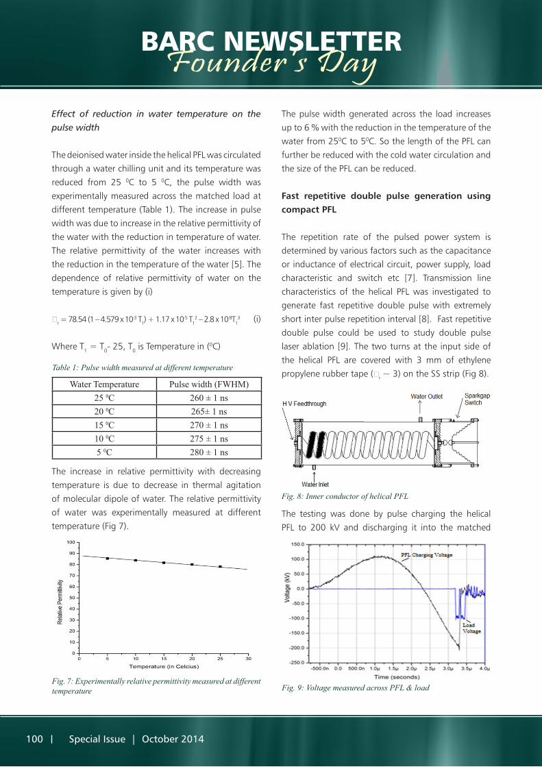
Fig. 8: Inner conductor of helical PFL
The testing was done by pulse charging the helical
PFL to 200 kV and discharging it into the matched
Fig. 9: Voltage measured across PFL & load

Special Issue | October 2014 101
BARC NEWSLETTERFounder’s Day22Ω resistive load, while discharging it generates two
fast pulses of 100 kV, 100 ns with 30 ns inter pulse
repetition interval across the load (Fig 9).
When high voltage was applied to the inner conductor
of the helical PFL and pulsed charged to 200 kV, the
water capacitor was fully charged where there was
no ethylene propylene rubber on the SS strip inner
conductor. At the input side of the PFL maximum
potential appears across the ethylene propylene
rubber, and the water capacitor was charged to
lesser extent due to its higher relative permittivity
compared to that of ethylene propylene rubber. The
self breakdown sparkgap switch closes at 200 kV and
the PFL discharges into the load. While discharging the
forward voltage wave travels towards the source and
voltage appears across the load. The voltage across the
load appears till it discharges up to the initial 2 turns.
Then there was less voltage across the water capacitor
above the ethylene propylene rubber, so no voltage
appears across the load. When the wave is reflected
from the input end due to the high impedance of
pulse transformer it again appears across the load
after the end of the 2 turns. So, the two pulses of 100
kV, 100 ns pulse width and interval of 30 ns between
the pulses appears across the load.
Conclusion
The compactness of the PFL depends on the length
of the conductor (l), dielectric constant (εr) and
temperature of the medium. Compact PFLs were
developed using high dielectric constant composite
dielectric material and an alternative topology using
helical inner conductor for pulse compression. A novel
technique is also developed using the transmission
line characteristics of the helical PFL for generation
of very fast repetitive pulse with very short inter pulse
repetition interval.
References
1. I.R. Smith, B.M. Novac, “An Introduction to the
Physics and Technology of Pulsed Power”, Taylor
and Francis Publisher (2010)
2. Nunnally W.C., “Critical component requirements
for compact pulse power system architectures”,
IEEE Trans. on Plasma Sci, 33,1262-1267 (2005)
3. S.K. Sharma, P. Deb, R. Shukla, T. Prabaharan & A.
Shyam, “Compact pulse forming line using barium
titanate ceramic material”, Rev. of Sci. Instrum,82,
115102 (2011)
4. C.R. Wilson, M.M. Turner and P.W. smith,
“Electromagnetic shock-wave generation in a
lumped element delay line containing nonlinear
ferroelectric capacitors” IEEE Trans. Electron
Devices 38, 767 (1991)
5. A.I. Gerasimov, “Water as insulator in pulsed
facilities”, Instruments and Experimental
Techniques, Vol 48. No. 2, pp 141 – 167 (2005)
6. S.K. Sharma, P. Deb, A. Sharma, R. Shukla, T.
Prabaharan, B. Adhikary & A. Shyam, “Compact
helical pulse forming line for longer duration
rectangular pulse generation”, Rev. of Sci.
Instrum., 066103 (2012)
7. Schneider L., Reed K., Harjes H., Pena G., Martinez
L., Harden M., presented at 12th IEEE International
Pulsed Power Conference, Vol 1, 523 - 527 (1999)
8. S.K. Sharma, P. Deb, Archana Sharma & A.
Shyam,“Fast double pulse system using the
transmission line characteristics of the PFL”, Rev. of
Sci. Instrum, 83,115108 (2012)
9. S.K. Sharma, P. Deb, R. Kumar, Archana Sharma
and A. Shyam, “Compact pulsed power driver for
double pulse effect studies in nanosecond laser
ablation”, IEEE Trans. Plasma Sci. 41 (10), 2609
(2013)