design and development of a quiet, self-thrusting …
TRANSCRIPT
1
Safety in Mines Research Advisory Committee
Final Project Report
DESIGN AND DEVELOPMENT OF A QUIET, SELF-THRUSTING BLAST HOLE DRILLING
SYSTEM
RW Ottermann NDL Burger AJ von Wielligh PR de Wet
Research Agency RE@UP, University of Pretoria Project number GAP 642 Date of report August 2001

2
EXECUTIVE SUMMARY Noise is a generic hazard common to all commodities and, to a greater or lesser extend affecting, all operations within mining. More people are exposed to the risk of noise- induced hearing impairment than to any other occupational hazard. Pneumatic percussion drills are a major contributor to noise-induced hearing impairment in mines. The design and development of a quiet, self-thrusting blast hole drilling system will reduce this risk. During this project such a drilling system was developed, tested and demonstrated. The primary output of this project is a quiet, ergonomically, reliable blast hole drilling system, which is used to drill suitable blast holes by workers responsible for drilling these holes. The system has to be safe and reliable with reduced hearing loss and higher productivity. After a problem survey was conducted a functional analysis was done from which a specification was drawn up. Although the current regulations state that a worker may be exposed to a maximum equivalent noise level of 85 dBA for 8 hours per day it was calculated and decided that an appropriate design level for the sound power level for the "quiet" rock drill would be 90 dBA as workers do not drill the full 8 hours. Different concepts were generated and evaluated. The preferred concept was presented to the SIMRAC technical committee for approval after which a detail design was done. An experimental development model (XDM) was built and surface tested. A design review was done and five prototype quiet rock drills were manufactured. These rock drills were tested on surface as well as underground. A marked reduction of sound levels was achieved with the quiet rock drill. The quiet rock drill consists of a standard Seco S215 pneumatic rock drill encapsulated in a composite material tube. The tube is pushed onto the rock face by a pneumatic cylinder and is sealed at the rock face by means of a flexible material. A lead screw mechanism, powered by a geared air motor, thrusts the drill forward. The exhaust air, dust, water and rock shavings as well as oil and grease are removed from the tube via an exhaust pipe a distance away where the air and water is dumped. A penetration rate not worse than that of existing drills was achieved with the quiet rock drill. This was one of the main design criteria for the project. Although sound levels of below 90dBA (the other main criteria) were not achieved directly adjacent to the quiet rock drill in the stope, it is envisaged that these levels will be achieved with an improved revised design. The testing of the prototype drills identified certain shortcomings, which will have to be addressed during further development of the drill. As a tendency exists for the introduction of drill rigs in mines it is also recommended that the quiet rock drill be incorporated in drill rigs. A drill rig with the quiet rock drill will have to be designed, built, tested and evaluated.

3
ACKNOWLEDGEMENTS The authors would like to express their gratitude to the Safety in Mines Research Advisory Committee (SIMRAC) for financial support of project GAP 642 and also for the interest and technical input of the SIMRAC Technical Committee. To Mr. Peter Hess and staff of Boart Longyear, Seco our sincere appreciation for their technical input as well as manufacturing and logistical support.

4
TABLE OF CONTENTS
1 INTRODUCTION................................................................................................. 7
2 METHODOLOGY ............................................................................................... 8
3 FUNCTIONAL ANALYSIS AND SPECIFICATION ...................................... 9
3.1 FUNCTIONAL ANALYSIS ............................................................................. 9 3.2 NOISE SPECIFICATION .............................................................................. 10
4 CONCEPT DESIGN........................................................................................... 12
4.1 COMPOSITE MATERIAL TUBE ................................................................... 12 4.2 FLEXIBLE BELLOWS................................................................................. 13 4.3 CONCEPT EVALUATION............................................................................ 13
4.3.1 Composite material tube concept ........................................................... 14 4.3.2 Flexible bellows concept ........................................................................ 14
4.4 SUPPORT OF THE DRILL............................................................................ 15 4.4.1 Support at rock face................................................................................ 16 4.4.2 Support at back of drill........................................................................... 17
4.5 DRILL TEST RIG........................................................................................ 18 4.6 CONCEPT TEST......................................................................................... 19
5 DETAIL DESIGN ............................................................................................... 20
5.1 DRILL DESIGN .......................................................................................... 20 5.2 FINITE ELEMENT ANALYSIS .................................................................... 21
6 EXPERIMENTAL DEVELOPMENT MODEL (XDM)................................ 22
7 TEST AND EVALUATION (SURFACE) ........................................................ 24
7.1 PERFORMANCE TESTS .............................................................................. 24 7.2 DURABILITY............................................................................................ 25
8 DESIGN REVIEW.............................................................................................. 26
9 TEST AND EVALUATION............................................................................... 27
9.1 SURFACE TESTING ................................................................................... 27 9.2 UNDERGROUND TESTING......................................................................... 28
10 CONCLUSSION AND RECOMMENDATIONS............................................ 31
11 REFERENCES.................................................................................................... 32
APPENDIX A : FUNCTIONAL ANALYSIS ........................................................33 APPENDIX B : LIST OF DESIGN CHANGES DURING DESIGN REVIEW40 APPENDIX C : FINITE ELEMENT ANALYSIS .................................................42 APPENDIX D : MANUFACTURING DRAWINGS ............................................43 APPENDIX E : COMBUSTION CHARACTERISTICS OF COMPOSITE
MATERIAL...................................................................................44
5
List of Figures Figure 3-1 System level functional analysis ..........................................................9 Figure 4-1 Composite material tube concept. .....................................................13 Figure 4-2 Flexible bellows concept. ....................................................................13 Figure 4-3 Support of the rock drill air leg activated linkage system ................15 Figure 4-4 Support of the rock drill making use of a modified “camlock” and A-
frame......................................................................................................16 Figure 4-5 A-frame support of the drill at the rock face .....................................17 Figure 4-6 Support of the drill at the back with “camlock” and spiking cylinder
..................................................................................................................18 Figure 4-7 Drill test rig .............................................................................................19 Figure 5-1 Experimental development model drill assembly ............................20 Figure 5-2a Depth indicator Figure 5.2b: Depth indicator on
outside ...................................................................................................21 Figure 6-1 Sectioned solid model of the assembled XDM quiet rock drill ......22 Figure 6-2 Inside of tube of quiet rock drill (XDM) ..............................................23 Figure 7-1 Photo of the quiet rock drill drilling into a granite block ..................25 Figure 9-1 Sound levels (dBA) around the prototype quiet rock drill tested on
surface ...................................................................................................27 Figure 9-2 Sound levels (dBA) around a standard muffled Seco 215 rock drill
tested on surface .................................................................................28 Figure 9-3 Photo of quiet rock drill being tested underground .........................29 Figure 9-4 Sound levels (dBA) around the prototype quiet rock drill tested
underground .........................................................................................29

6
List of Tables
Table 3.2-1 Time exposure equivalent to an 85dBA 8 hour noise shift. (Heyns :2001) ....................................................................................................10

7
1 INTRODUCTION
Noise is a generic hazard common to all commodities and, to a greater or lesser extend affecting, all operations within mining. More people are exposed to the risk of noise- induced hearing impairment than to any other occupational hazard. Pneumatic percussion drills are a major contributor to noise-induced hearing impairment in mines. The design and development of a quiet, self-thrusting blast hole drilling system will reduce this risk. In addition to the cost of compensation and reduced productivity resulting from lost shifts, hearing conservation programmes (which have proven largely ineffective for a number of reasons) are expensive to implement and maintain. The impact of hearing loss/interference on productivity and safety also results in reductions in profitability. This indicates that engineering measures to control the noise hazard, which are generally accepted as the preferred approach to hearing conservation, offer better prospects for success than receptor control or personal protection strategies. Some progress has been made during previous work by SIMRAC to develop a quiet drilling system, GEN 207 (Harper and Scanlon, 1997) and GEN 311 (Harper and Scanlon, 1998). The experimental development model, GEN 311, showed promise in reducing sound power levels but has a number of drawbacks, which precludes it from being implemented in production. It was decided by SIMRAC that a new approach to the development of a quiet rock drill is needed. In the request for proposal and during the brief by the SIMRAC technical committee it was stated that no further literature or technological survey should be conducted as this had been done previously and could inhibit a new innovative approach to the problem. This is the final report on project GAP 642. During this project a quiet self-thrusting blast hole drilling system was developed, tested and demonstrated.

8
2 METHODOLOGY
The following methodology was followed during this project: ? After gathering information from industry a functional analysis was
done. ? From the functional analysis the requirements for the system were
finalised and the system specification and design parameters drawn up.
? Different concepts were generated and evaluated against the system specification and design parameters.
? A test rig for percussion drills was built to evaluate and demonstrate a mock-up of the selected concept.
? The selected concept was then presented to the SIMRAC Technical Committee for approval. The concept was also presented to other interested parties from industry. Recommendations and concerns about the concept were taken into account during the design.
? The selected concept was designed in detail, followed by a design audit.
? An experimental development model (XDM) of the drill was manufactured and commissioned.
? The XDM was tested and evaluated on surface, making use of the test rig and a norite block.
? A design review was done and the design improved. ? Five drills as required for project deliverables were manufactured. ? The drills were tested and evaluated on surface as well as
underground. These tests only involved basic functional evaluation as requested (sound levels and penetration rate) and did not involve operational evaluation and durability testing.

9
3 FUNCTIONAL ANALYSIS AND SPECIFICATION 3.1 Functional analysis
A functional analysis based on the requirements for a quiet, self-thrusting blast hole drilling system was done from which a system specification and design parameters were compiled. In figure 3.1 the system level of the functional analysis is shown and the complete functional analysis is listed in Appendix A. The quiet rock drill (system) has a reduced noise specification (see paragraph 3.2), it has to be self-propelled and the specification on penetration rate is the same as the standard pneumatic percussion rock drills. See Appendix A.
SYSTEM LEVEL Figure 3-1 System level functional analysis
QUIET ROCKDRILL
QUIET DRILLING SELF-PROPELLED STANDARD DRILL
Sound from drill shaft
Sound from drill
Forward Back
Thrust N=1750N V=370 mm/min
Rapid Speed V=370 mm/min

10
3.2 Noise specification
In order to arrive at a sensible specification for the overall noise level of a "quiet" rock drill, it was necessary to make some assumptions. The current regulations state that a worker may be exposed to a maximum equivalent noise level of 85 dBA for 8 hours per day, see table 3.2-1 (Occupational Health and Safety Act and Regulations, 85/1993, Regulation 2281,Sub-regulation 7).
(dBA) Max exposure per day (hours)
Maximum exposure per week (hours)
85 8 40 88 4 20 91 2 10 94 1 5 97 0,5 2,5
100 15 minutes 75 minutes
Table 3.2-1 Time exposure equivalent to an 85dBA 8 hour noise shift. (Heyns :2001)
It is important to note that these are cumulative values for exposure. Thus, if a worker has been exposed to a level of 91dBA for two hours then for the rest of the working day such a worker should be in a quiet (< 75 dBA) environment for the remaining six hours. Another important peculiarity of noise levels is that if one rock drill operating in a stope generates noise to a level of say 85 dBA then adding a similar rock drill in the same general area will increase the overall noise level to 88 dBA. Four drills will result in the noise level reaching 91 dBA. Taking the above points into consideration it is very difficult to set a single value as a design specification for a “quiet” rock drill. The report for GEN 503 on hand-arm vibration measurements on rock drill operators, states that the average time that the operators are drilling blast holes per shift is 2 hours. During this time a particular operator’s machine will only be drilling for about half of that time (one hour).
The following was then assumed: ? There are four drills per panel. ? The average drilling time per shift is 2 hours. ? At any given time only two drills are operating.
11
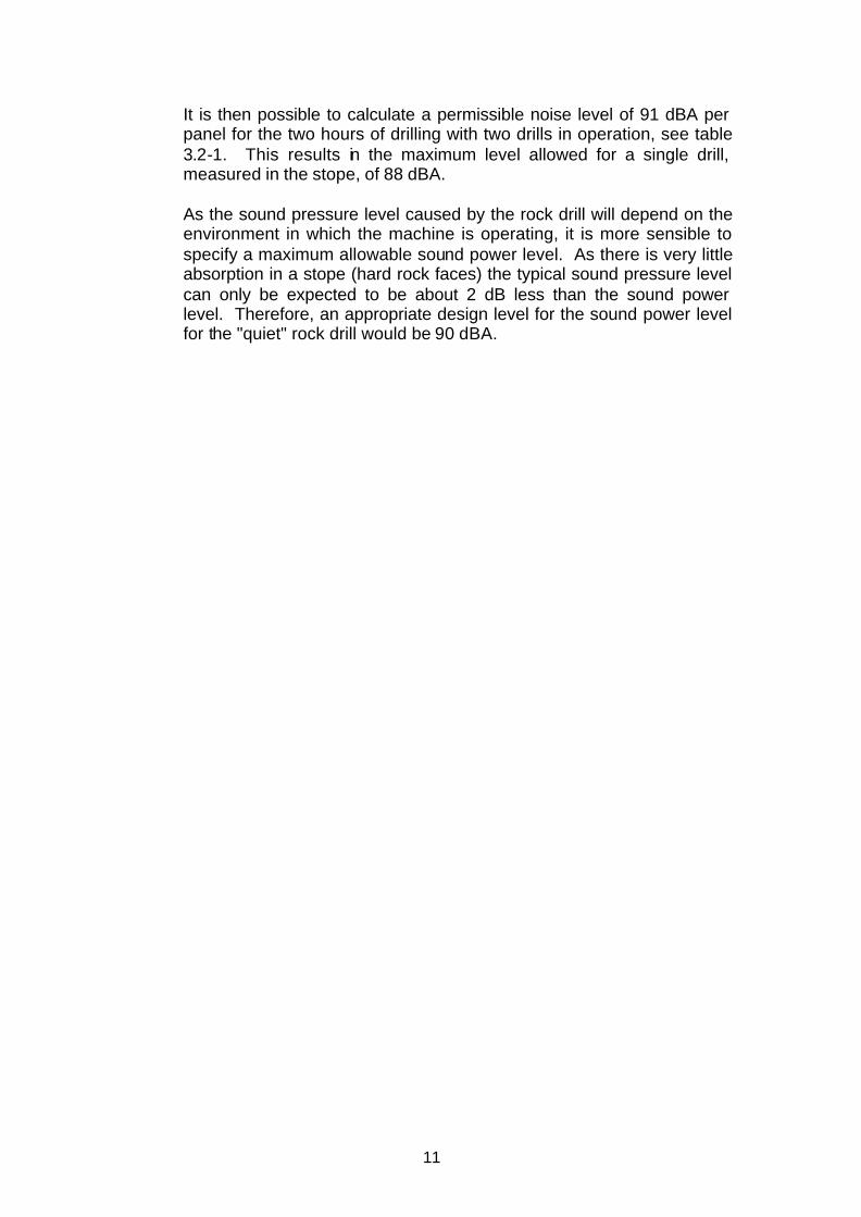
It is then possible to calculate a permissible noise level of 91 dBA per panel for the two hours of drilling with two drills in operation, see table 3.2-1. This results in the maximum level allowed for a single drill, measured in the stope, of 88 dBA. As the sound pressure level caused by the rock drill will depend on the environment in which the machine is operating, it is more sensible to specify a maximum allowable sound power level. As there is very little absorption in a stope (hard rock faces) the typical sound pressure level can only be expected to be about 2 dB less than the sound power level. Therefore, an appropriate design level for the sound power level for the "quiet" rock drill would be 90 dBA.

12
4 CONCEPT DESIGN
Different concepts were generated but in order to arrive at the appropriate sound level, the noise has to be contained and removed from the operations area. Two concepts were generated that encapsulate the drill while the exhaust air and water is ducted away from the operation via a pipe. Dust caused by the drilling is also contained and ducted away, which reduces the health risk with related diseases. A possible addition is a waste unit where the oil and grease can be recovered to limit pollution.
The two final concepts are discussed in the following paragraphs:
4.1 Composite material tube
The drill is encapsulated in a composite material tube, which is pushed onto the rock face. The tube is sealed at the rock face by means of a flexible material. A thrusting mechanism, powered by a geared air motor, thrusts the drill forward. The exhaust air, dust, water and rock shavings as well as oil and grease, are removed from the tube via an exhaust pipe a distance away where the air and water is dumped. The possibility exists that the oil and grease can be separated from the air and water by a waste unit comprising of centrifuges to reduce pollution.
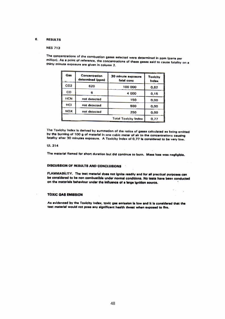
The tube is manufactured from a composite material that has been tested by the CSIR: Division of Building Technology and approved for underground applications. In Appendix E, the test report on the combustion characteristics of the material as well as a letter by the Department of Minerals and Energy approving the material for underground use is attached.

13
Figure 4-1 Composite material tube concept.
4.2 Flexible bellows
The drill is encapsulated in a flexible bellows, which extends up to the rock face. A standard air leg thrusts the drill forward. As with the composite material tube concept, the exhaust air, water, rock shavings, oil and grease are removed from the working area via a pipe.
Figure 4-2 Flexible bellows concept.
4.3 Concept evaluation
After evaluation of the concepts the composite material tube concept was selected for further development and detail design. Some of the positive and negative factors of both concepts are listed below:
14
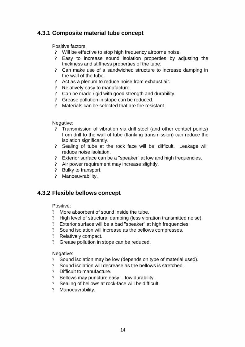
4.3.1 Composite material tube concept
Positive factors: ? Will be effective to stop high frequency airborne noise. ? Easy to increase sound isolation properties by adjusting the
thickness and stiffness properties of the tube. ? Can make use of a sandwiched structure to increase damping in
the wall of the tube. ? Act as a plenum to reduce noise from exhaust air. ? Relatively easy to manufacture. ? Can be made rigid with good strength and durability. ? Grease pollution in stope can be reduced. ? Materials can be selected that are fire resistant.
Negative: ? Transmission of vibration via drill steel (and other contact points)
from drill to the wall of tube (flanking transmission) can reduce the isolation significantly.
? Sealing of tube at the rock face will be difficult. Leakage will reduce noise isolation.
? Exterior surface can be a "speaker" at low and high frequencies. ? Air power requirement may increase slightly. ? Bulky to transport. ? Manoeuvrability.
4.3.2 Flexible bellows concept
Positive: ? More absorbent of sound inside the tube. ? High level of structural damping (less vibration transmitted noise). ? Exterior surface will be a bad "speaker" at high frequencies. ? Sound isolation will increase as the bellows compresses. ? Relatively compact. ? Grease pollution in stope can be reduced. Negative: ? Sound isolation may be low (depends on type of material used). ? Sound isolation will decrease as the bellows is stretched. ? Difficult to manufacture. ? Bellows may puncture easy – low durability. ? Sealing of bellows at rock-face will be difficult. ? Manoeuvrability.
15
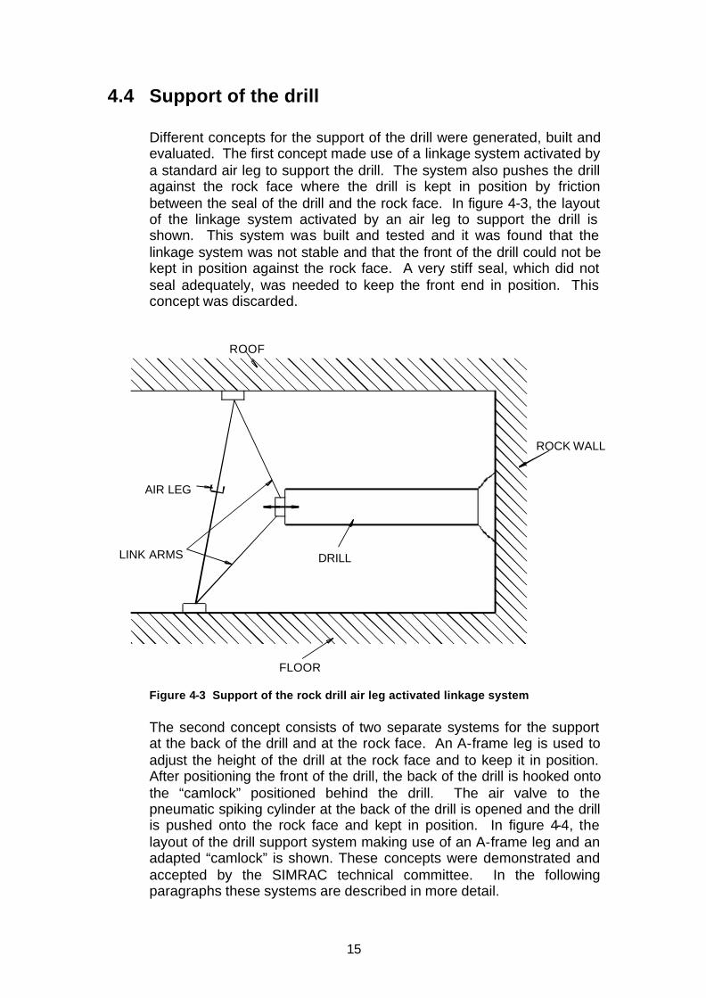
4.4 Support of the drill Different concepts for the support of the drill were generated, built and evaluated. The first concept made use of a linkage system activated by a standard air leg to support the drill. The system also pushes the drill against the rock face where the drill is kept in position by friction between the seal of the drill and the rock face. In figure 4-3, the layout of the linkage system activated by an air leg to support the drill is shown. This system was built and tested and it was found that the linkage system was not stable and that the front of the drill could not be kept in position against the rock face. A very stiff seal, which did not seal adequately, was needed to keep the front end in position. This concept was discarded.
Figure 4-3 Support of the rock drill air leg activated linkage system The second concept consists of two separate systems for the support at the back of the drill and at the rock face. An A-frame leg is used to adjust the height of the drill at the rock face and to keep it in position. After positioning the front of the drill, the back of the drill is hooked onto the “camlock” positioned behind the drill. The air valve to the pneumatic spiking cylinder at the back of the drill is opened and the drill is pushed onto the rock face and kept in position. In figure 4-4, the layout of the drill support system making use of an A-frame leg and an adapted “camlock” is shown. These concepts were demonstrated and accepted by the SIMRAC technical committee. In the following paragraphs these systems are described in more detail.
LINK ARMS
AIR LEG
FLOOR
ROCK WALL
DRILL
ROOF

16
Figure 4-4 Support of the rock drill making use of a modified “camlock” and A-frame
4.4.1 Support at rock face
At the rock face the drill is supported by an A-frame leg, which latches onto the drill at the front end of the fibreglass tube. The height is adjusted by varying the angle at which the leg stands. The two sharpened legs, of the of the A-frame, anchor onto the floor. In figure 4-5, the A-frame and the drill is shown.

17
Figure 4-5 A-frame support of the drill at the rock face
4.4.2 Support at back of drill
The drill is supported at its back by a modified “camlock” roof support. A lock plate with a hook for the drill to latch on is placed around the pipe of the “camlock”. The drill is placed into the hook on the “camlock” positioned behind the drill with the correct height pre-selected. If the air valve to the pneumatic spiking cylinder at the back of the drill is opened, the pneumatic cylinder pushes the drill onto the rock face and the drill is kept in position. The spiking cylinder is a pneumatic cylinder, which forms an integral part of the backplate on the drill. In figure 4.6 the “camlock” and the spiking cylinder at the back of the drill is shown.

18
Spiking Cylinder
Figure 4-6 Support of the drill at the back with “camlock” and spiking cylinder
A lock plate is placed around each of the two pipes of the “camlock”. The height of the hook on the plate is adjusted by sliding the lock plate up or down. The lock plate is locked in position if turned, which automatically takes place when loaded on one side by hooking the drill onto it.
4.5 Drill test rig
A test rig for testing percussion drills was built to evaluate these drills. The test rig was built for comparative testing and evaluation of rock drills. The drill rig has a load cell mounted in the front to measure the impact forces exerted by the drill, which gives an indication of impact forces. This was done to ensure that the quiet rock drill does not at a lower performance. In figure 4.7 the drill test rig is shown.

19
Figure 4-7 Drill test rig
4.6 Concept test
In order to investigate the effectiveness of enclosing the drill in a tube, to reduce noise emission, a mock-up of the selected concept (a drill encapsulated in a composite material tube) was built and tested. A standard drill was placed inside a PVC tube and a flexible exhaust tube was used to vent the spent air a distance of approximately 10m away. The measurements for the concept show a significant reduction in noise levels. For the mock-up the averaged, measured noise level at the most likely position of the ear of the operator was 90 dBA compared to 110 dBA for the standard drill.

20
5 DETAIL DESIGN 5.1 Drill design
The selected concept with the composite material tube was designed in detail. The mechanics of the moving parts were designed and a finite element analysis of the tube was done to determine the design of the structure. To isolate the vibrations of the drill from the tube, absorbing polyurethane mountings were designed. In order to be able to accurately design these rubber mountings, vibration measurements were done on a percussion drill. In figure 5-1 the assembly drawing of the experimental development model (XDM) drill is shown. A full set of detail drawings of the XDM was made.
Figure 5-1 Experimental development model drill assembly
The basic design consists of an outer shell manufactured from fibreglass with guides moulded into the shell on the inside. The polyurethane wheels supporting the drill are running on these guides. The forward propulsion is provided by means of a geared air motor (650 W) running at 31.5 rpm (no load speed) via a lead screw. The
Polyurethane wheels
Lead screw Geared air motor
Drill steel S215 drill
Composite tube

21
screw is mounted in plain bearings, manufactured from Ertalon (nylon). The Ertalon is again isolated from the main structure with polyurethane to get the necessary damping. A depth indicator, indicating the position of the drill was designed as the drill runs inside the tube and its position cannot be seen from the outside. A geared device driven from the lead screw moves the indicator, which can be seen through a small window, forward and backward. In figure 5.2a the depth indicator is shown and in figure 5.2b the depth indicator as seen from the outside is possible.
Figure 5-2a Depth indicator Figure 5.2b: Depth indicator on outside
After the design audit on the drill was completed, the design was presented to the relevant SIMRAC Technical Committee, which approved the design.
5.2 Finite Element Analysis
Both static and modal finite element analyses were conducted on the composite material tube and static finite element analyses were done for the lead screw of the drill. The strength margins on the tube are very large due to the fact that the design is driven by stiffness and not strength. The design of the tube is such that the natural frequencies are considerably higher than the 40 to 50 Hz operating frequency of the drill. In appendix C a summary of the finite element analysis as well as the design and the manufacturing technique of all the composite material components is attached.
22
6 EXPERIMENTAL DEVELOPMENT MODEL
(XDM)
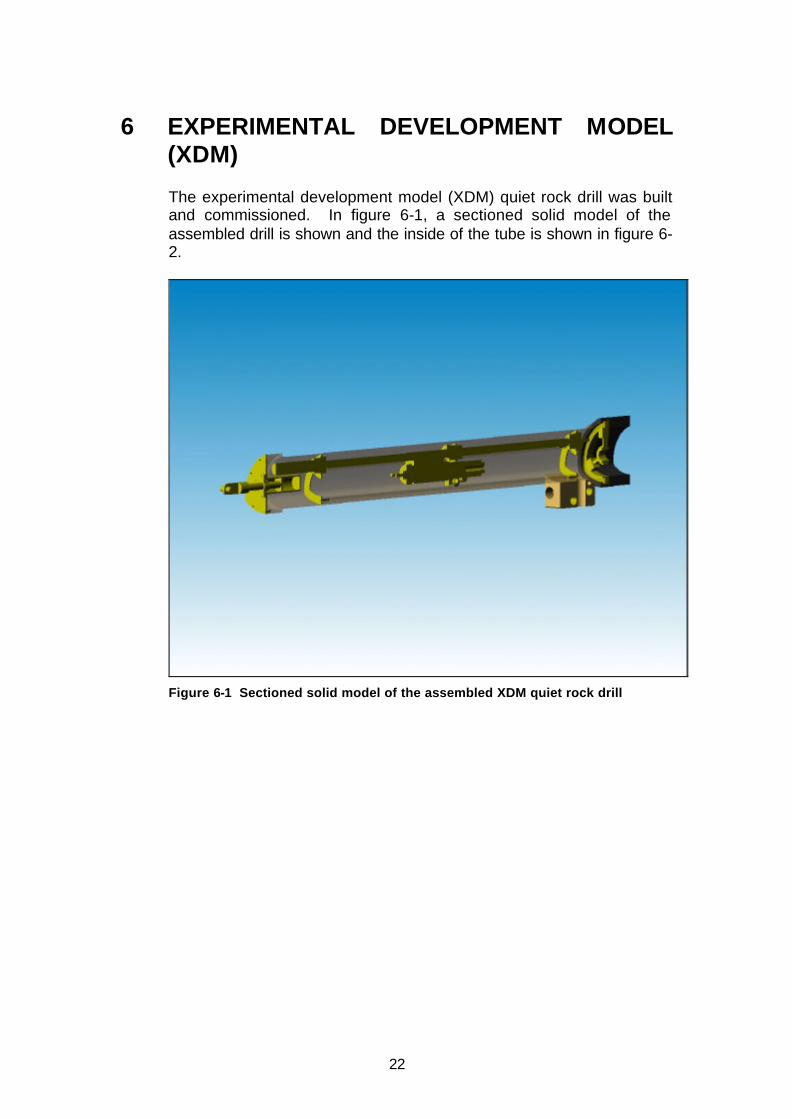
The experimental development model (XDM) quiet rock drill was built and commissioned. In figure 6-1, a sectioned solid model of the assembled drill is shown and the inside of the tube is shown in figure 6-2.
Figure 6-1 Sectioned solid model of the assembled XDM quiet rock drill

23
Figure 6-2 Inside of tube of quiet rock drill (XDM)

24
7 TEST AND EVALUATION (SURFACE) 7.1 Performance tests
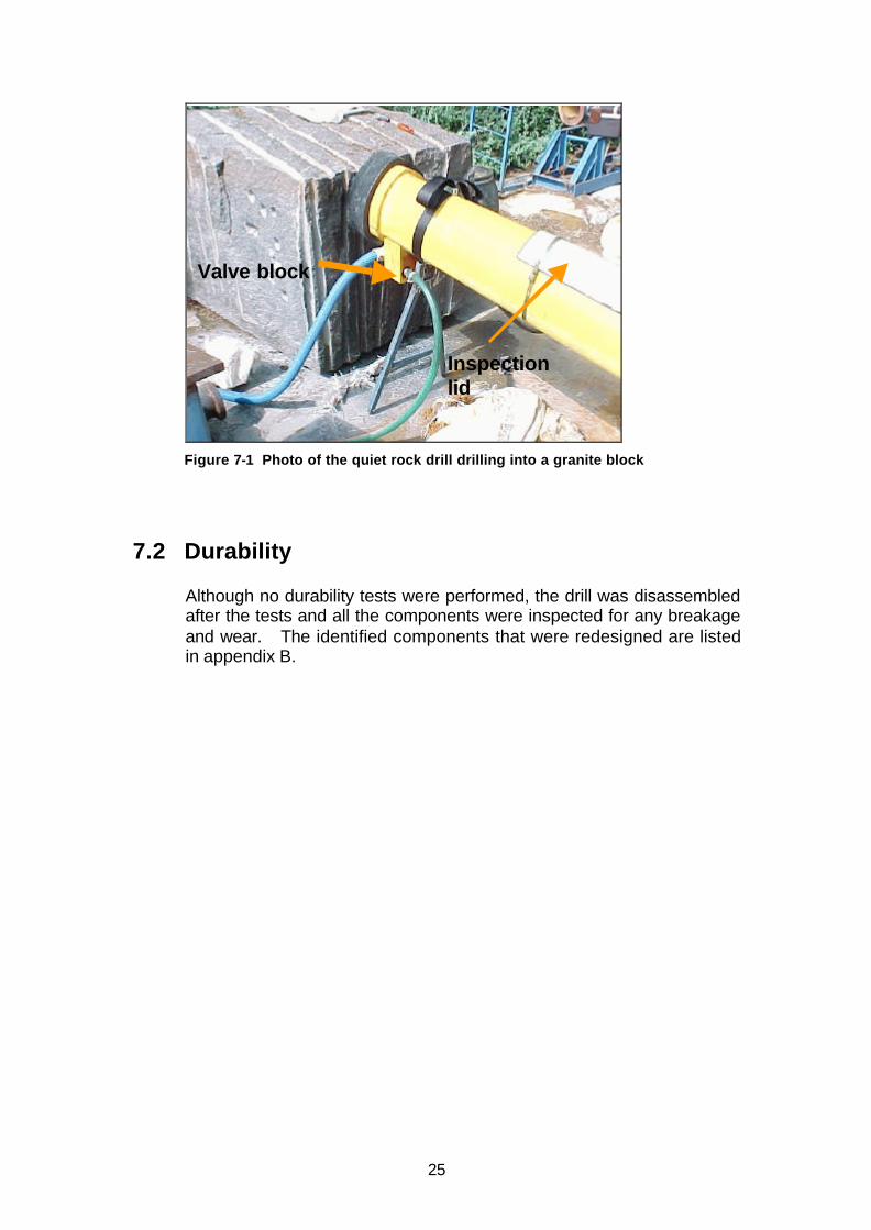
Surface tests of the XDM quiet rock drill, drilling into a norite block (210 to 290 MPa) were done. The tests were done in an open area to reduce the effect of reflections from hard surfaces adding to the sound pressure level. In figure 7-1 a photo of the drill, drilling into a norite block is shown. A standard rock drill was also tested to get comparative results. Although the operator of the quiet rock drill will not be in the same position as the operator of the standard rock drill, for comparative reasons noise level measurements were taken at the same position for both drills. The noise level was measured at the most likely position of the head of the operator (500mm behind and 500mm above the back of the drill). The penetration rate into the rock was measured in mm per minute. The hardness of the norite rock was 210 to 290MPa. The following results were achieved:
Noise level Penetration rate (dBA) (mm/min.)
XDM quiet rock drill: 90 500 Standard rock drill: 110 500 The results of the tests show that although the penetration rate of the two drills is roughly the same the XDM quiet rock drill has a marked reduction in sound level measured.
25
Valve block
Inspection lid
Figure 7-1 Photo of the quiet rock drill drilling into a granite block
7.2 Durability
Although no durability tests were performed, the drill was disassembled after the tests and all the components were inspected for any breakage and wear. The identified components that were redesigned are listed in appendix B.

26
8 DESIGN REVIEW
Following the test and evaluation of the XDM quiet rock drill a design review was done. The changes made during the design review are listed in appendix B. In appendix D the complete set of manufacturing drawings of the drill is attached including an assembly drawing.

27
9 TEST AND EVALUATION 9.1 Surface testing
Surface tests of the prototype quiet rock drill, drilling into a norite block were done. The tests were done in an open area to reduce the effect of reflections from hard surfaces adding to the sound pressure level. The noise levels were measured at predetermined points spaced on 1 m contours between 1m and 4m around the drill and the achieved results are shown in figure 9-1. A standard muffled Seco 215 rock drill was also tested with the same test pattern and the comparative results are shown in figure 9-2.
Figure 9-1 Sound levels (dBA) around the prototype quiet rock drill tested on surface

28
Figure 9-2 Sound levels (dBA) around a standard muffled Seco 215 rock drill tested on surface
By comparing the sound levels in figure 9-1 and figure 9-2 the marked reduction in sound levels of the prototype quiet rock drill can be seen. As can be seen from figure 9-1 sound levels of below 90 dBA were not achieved directly adjacent to the quiet rock drill. The sound levels are only below 90 dBA, a distance of 1 to 2m away from the drill. As the operator will only be close to the drill for a very short period of time and for the majority of time will be further than 2m away this may not pose a problem. It is however envisaged that sound levels below 90 dBA will be achieved with an improved revised design.
9.2 Underground testing
The prototype quiet rock drill was tested underground at the Bleskop shaft, Anglo Platinum. The tests were done in a 1 to 1.2m stope. Figure 9-3, shows the quiet rock drill being tested underground. The noise levels were measured at predetermined points, according to the same test pattern as used earlier, around the drill and the results are shown in figure 9-4. Although no comparative noise measurements were taken at the predetermined points around a standard rock drill, single value measurements were taken in the same stope. These

29
sound level values were between 115 and 118 dBA next to the operators head.
Figure 9-3 Photo of quiet rock drill being tested underground
Figure 9-4 Sound levels (dBA) around the prototype quiet rock drill tested underground

30
The increase in sound levels between the surface and underground tests (see figures 9-1 and 9-4) can partly be attributed to the footwall and hanging wall of the 1.2 m stope. Another factor was air and therefore noise leaking through the inspection lid and depth indicator, which had broken. The build up of backpressure due to the blockage of the exhaust pipe aggravated these leaks. A significant reduction in noise values is anticipated with an improved revised design, which will address and rectifies these problems. Although the drill was thoroughly tested on surface a number of new problems were encountered during underground testing. The following problems, which will necessitate design modifications, were identified: ? Too heavy – reduce weight. ? Difficult to handle – put solid handles on top and side. ? Excessive corrosion on all steel parts – protect against corrosion. ? Corrosion in air motor – build in water trap. ? Drill stops occasionally due to too much pressure from thrust motor
– add pressure regulator. ? Exhaust pipe blocks -- shorten pipe to reduce backpressure.
-- bend in valve block is too sharp. ? Drill runs full of water when drilling upward – add second exhaust at
back. ? Eliminate water sprayed from the front of the drill. The water curtain
suppressing dust is no longer needed as dust is contained. ? Inspection lid leaking and not watertight. Also cumbersome to open
and close – design new lid. ? Valve block is too big (cannot drill in bottom corner) – redesign. ? Depth indicator window was damaged – change design and add
protector. ? Front support for the drill difficult to handle.
31
10 CONCLUSSION AND RECOMMENDATIONS
A quiet, self-thrusting blast hole drilling system was developed and demonstrated. The system will have reduced hearing loss and increased productivity as operators can operate more than one system. A considerable reduction in sound levels was achieved with comparable drilling speeds to standard pneumatic drills. Although sound levels of below 90 dBA were not achieved directly adjacent to the quiet rock drill, the sound levels measured on surface are below 90 dBA a distance of 1 to 2m away from the drill. As the operator will only be close to the drill for a very short period of time and for the majority of the time he will be further than 2m away, this may not pose a problem. It is however envisaged that the sound levels of below 90 dBA, measured underground, will be achieved with an improved revised design. The tests of the quiet rock drill identified certain shortcomings including the weight and manoeuvrability (see paragraph 9), which will have to be addressed during further development of the drill. For the further development of the drill the following is recommended: ? Do a design review to address shortcomings of drill, i.e. reduce
weight, reduce noise levels etc. (See paragraph 9.2). ? Test drill. ? Change drill or build new drills until the required performance is
achieved. ? Do underground operational evaluations. ? Do reliability tests. ? Finalise design. As a tendency exists for the introduction of drill rigs in mines it is also recommended that the quiet rock drill be incorporated in drill rigs. A drill rig with the quiet rock drill will have to be designed, built, tested and evaluated. The use of the quiet rock drill in a drill rig will solve the problem of manoeuvring, as size and weight will not be a problem on a rig.
32
11 REFERENCES Harper, G.S., Scanlon, T., November 1997, Develop a quiet non-atmosphere polluting blast hole drilling system, Safety in Mines Research Advisory Committee, GEN 207. Harper, G.S., Scanlon, T., January 1998, Evaluation and further development of a quiet non-atmosphere polluting blast hole drilling system, Safety in Mines Research Advisory Committee, GEN 311. Heyns, P.S, 2001 Limitation of Exposure to Noise, COL 714 Occopational Health and Safety Act and Regulations, 85/1993 Van Niekerk, J.L., Heyns, P.S., Heyns M., Hassall, J.R., The measurement of vibration characteristics of mining equipment and impact percussive machines and tools. Safety in Mines Research Advisory Committee, GEN 503.

33
APPENDIX A : FUNCTIONAL ANALYSIS

34
SYSTEM LEVEL
QUIET ROCKDRILL
QUIET DRILLING < 90dBA
SELF PROPELLED STANDARD DRILL
Sound from drill shaft
Sound from drill
Forward Back
Thrust N=1750N V=370 mm/min
Rapid Speed V=370 mm/min

35
MISSION LEVEL
? Use of existing proven equipment ? Acceptable life expectancy ? Compatible ? Maintainable ? Reliable ? Compact ? Light ? Robust ? Simplicity ? Visible ? Sound power emission < 90 dBA ? Safety ? Self propelled ? Quick/easy drill steel assembly ? Flame proof ? Materials with low spark temperature ? Low vibration levels ? Remote control
Scope of problem
Support mining activity 0.0
Drill holes 1.0
Drill functional 2.0

36
SYSTEM LEVEL FUNCTIONAL DIAGRAM Scope of problem
Position 1.1
Forward propelled 1.3
Activation of drill 1.4
Backward propelled 1.5
Drill holes 1.0
Prevent drill falling over 1.2
Drill is functional 2.0

37
FIRST LEVEL: FUNCTIONAL DIAGRAM
No No No No
Place in position 1.1.2
Anchor in ground 1.1.4
Secure to rock face 1.1.5
Prevent falling over 1.2
Position 1.1
Carry to stope 1.1.1
Assemble air water legs 1.1.3
Forward propelled 1.3
Activate rapid forward motion
1.3.1
Is drill steel in contact with rock face ?
Activate drill 1.4
Apply thrust 1.3.2
Is hole at correct depth?
Backward propelled 1.5
Active drill 1.4
Active water/air? 1.4.1
Depth? Hole complete 1.4.2
Backward propelled 1.5
Activate rapid backward motion
1.5.1
Is drill steel out of hole
Remove drill 1.6

38
FUNCTION DESIGN PARAMETERS
1.1 Position 1.1.1 Carry to stope Light < 30kg/person
Carry handle – Ergonomically acceptable Bright colour (bright yellow) No protruding extension Robust (drop 3.5m onto 50mm steel ball –Denting not to affect function) Maintainable Corrosion resistance No lose items Two man operation
1.1.2 Place in position Maximum length: 2000 mm Two man operation No loose parts Maximum weight: 60kg (for 2 man operation)
1.1.3 Anchor in ground Two man operation No loose parts Maximum thrust: 1750N No rotation of drill
1.1.4 Secure to rock face Two man operation No loose parts Maximum thrust: 1750N No rotation of drill
1.2 PREVENT FALLING OVER
1.3 FORWARD PROPULSION
1.3.1 Activate rapid forward motion Distance to travel: minimum Maximum speed: v= 370 mm/min Maximum air consumption: 55l/sec @500 kPa. Maximum sound power emission: 90 dBA
1.3.2 Apply thrust Thrust needed for drilling: 1750N Air consumption for air motor 16.5 l/s Air pressure for motor: 500 kPa Maximum speed for drilling: V=370 mm/min (40 mm drill bit) Maximum air consumption: 55l/sec Maximum sound power emission: 90 dBA Drill steel release mechanism

39
1.4 ACTIVATE DRILL 1.4.1 1.4.2
Activate water and air Hole complete
Maximum water consumption: 11 /min @ 400 kPa Maximum air consumption: 55 l/sec Maximum sound power emission: 90 dBA – Effective flushing of hole Depth: 1.2 – 2 m for 40 mm drill bit
1.5 1.5.1 1.6
BACKWARD PROPULSION Activate rapid backward motion REMOVE DRILL
Minimum speed: 370 mm/min Distance to travel: 1200 mm + 100 mm Maximum air consumption: 55 l/sec Maximum sound power emission: 90 dBA Maximum pull: 1570 N Drill steel release mechanism Air pressure for motor: 500 kPa Light < 30kg Carry handle – Ergonomically acceptable Bright colour (Bright yellow) No protruding extension Robust (drop 0.5 m onto 50mm steel ball – denting not to affect function) Maintainable Corrosion resistance No lose items Two man operation

40
APPENDIX B : LIST OF DESIGN CHANGES DURING DESIGN REVIEW

41
APPENDIX B: LIST OF DESIGN CHANGES DURING DESIGN REVIEW
? Design of hanger brackets, connecting the rock drill to the lead screw, was changed to improve stability and durability (durability problem).
? The bottom polyurethane wheel was replaced with a nylon wheel (durability problem).
? The standard Boart Longyear lead screw was used (durability problem with first design).
? Due to the fact that the pitch of the Boart Longyear lead screw differs the geared air motor was changed to a 30Nm air motor.
? The valve to control the flow of the water is incorporated into the back of the standard drill. Boart Reg no. TD 0871.
? A pneumatic cylinder (spiking cylinder) was mounted in the back plate for pushing the drill against the rock face.
? Air supply hose inside of tube increased to 19mm to reduce pressure drop.
? Valve block design changed to incorporate air inlet valve. ? Valve block material changed (durability problem). ? New design of seal against rock face. ? Inspection hole was added to tube. ? Tube shortened to accommodate shorter drill rod, 1,2 m. ? Depth indicator added. ? Thickness of tube reduced to 3mm. ? Thickness of endplates increased to 10mm to accommodate thrust. ? Coupling between air motor and lead screw was changed to
achieve better life (durability problem). ? Support at back of drill making use of a standard “camlock”. ? Support of drill at the rock face making use of an A-frame.

42
APPENDIX C : FINITE ELEMENT ANALYSIS
(SEE ATTACHED CD)

43
APPENDIX D : MANUFACTURING DRAWINGS

44
APPENDIX E : COMBUSTION CHARACTERISTICS OF COMPOSITE MATERIAL

45

46

47
48

49