design and construction of concrete-filled steel tube column
TRANSCRIPT
MoriEarthquake Engineering and Engineering Seismology 51 Volume 4, Number 1, September 2003, pp. 51–73
no, Tsuda: Design and Construction of Concrete-Filled Steel Tube Column System in Japan 51
Design and Construction of Concrete-Filled Steel Tube Column System in Japan
Shosuke Morino 1) Keigo Tsuda 2)
1) Department of Architecture, Faculty of Engineering, Mie University, 1514 Kamihamo-cho, Tsu,
Mie, 514-8507, Japan. 2) Department of Environmental Space Design, Faculty of Environmental Engineering, The
University of Kitakyushu, Hibikino 1-1, Wakamatsu-ku, Kitakyushu, Fukuoka, 808-0135, Japan.
ABSTRACT
The concrete-filled steel tube (CFT) column system has many advantages compared with the ordinary steel or the reinforced concrete system. One of the main advantages is the interaction between the steel tube and concrete: local buckling of the steel tube is delayed by the restraint of the concrete, and the strength of concrete is increased by the confining effect of the steel tube. Extensive research work has been done in Japan in the last 15 years, including the “New Urban Housing Project” and the “US-Japan Cooperative Earthquake Research Program,” in addition to the work done by individual universities and industries that presented at the annual meeting of the Architectural Institute of Japan (AIJ). This paper introduces the structural system and discusses advantages, research findings, and recent construction trends of the CFT column system in Japan. The paper also describes design recommendations for the design of compression members, beam-columns, and beam-to-column connections in the CFT column system.
INTRODUCTION
Since 1970, extensive investigations have verified that framing systems consisting of concrete-filled steel tube (CFT) columns and H-shaped beams have more benefits than ordinary reinforced concrete and steel systems, and as a result, this system has very frequently been utilized in the construction of middle- and high-rise buildings in Japan. In 1961, Naka, Kato, et al., wrote the first technical paper on CFT in Japan. It discussed a circular CFT compression member used in a power transmission tower. In 1985, five general
contractors and a steel manufacturer won the Japan’s Ministry of Construction proposal competition for the construction of urban apartment houses in the 21st century. Since then, these industries and the Building Research Institute (BRI) of the Ministry of Construction started a five-year experimental research project called New Urban Housing Project (NUHP), which accelerated the investigation of this system. Another five-year research project on composite and hybrid structures started in 1993 as the fifth phase of the U.S.-Japan Cooperative Earthquake Research Program, and the investigation of the CFT column system was included in the program. Research findings obtained from this project
52 Earthquake Engineering and Engineering Seismology, Vol. 4, No. 1
formed present design recommendations for the CFT column system.
This paper describes the outline of the CFT column system, introduces advantages, discusses research and construction of this system, and then details the provisions in the design standards published by the Architectural Institute of Japan (AIJ) [1].
OUTLINE OF CFT COLUMN SYSTEM
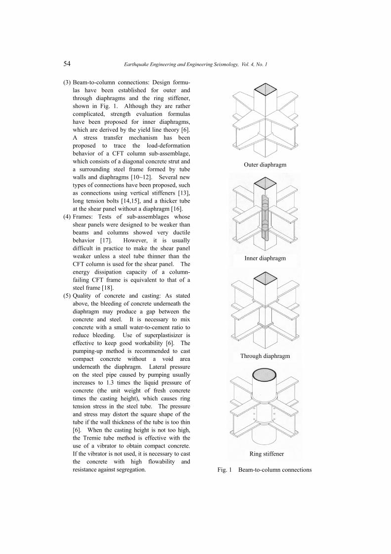
Structural System Figure 1 shows typical connections between a
CFT column and H-shaped beams often used in Japan. The connection is fabricated by shop welding, and the beams are bolted to the brackets on-site. In the case of connections using inner and through-type diaphragms, the diaphragm plates are located inside the tube, and a hole is opened for concrete casting. A cast steel ring stiffener is used for a circular CFT column. In the case of a ring stiffener and an outer diaphragm, there is no object inside the tube to interfere with the smooth casting of the concrete. Concrete casting is usually done by Tremie tube or the pump-up method. High strength and ductility can be obtained in the CFT column system because of the advantages mentioned below. However, difficulty in properly compacting the concrete may create a weak point in the system, especially in the case of inner and through-type diaphragms where bleeding of the concrete beneath the diaphragm may produce a gap between the concrete and steel. There is currently no way to ensure compactness or to repair this deficiency. To compensate, high-quality concrete with a low water-content and a superplasticizer for enhanced workability is used in construction.
Advantages The CFT column system has many advantages
compared with ordinary steel or reinforced concrete systems. The main advantages are listed below:
(1) Interaction between steel tube and concrete: Local buckling of the steel tube is delayed,
and the strength deterioration after the local buckling is moderated, both due to the restraining effect of the concrete. On the other hand, the strength of the concrete is increased due to the confining effect provided by the steel tube, and the strength deterioration is not very severe, because concrete spalling is prevented by the tube. Drying shrinkage and creep of the concrete are much smaller than in ordinary reinforced concrete.
(2) Cross-sectional properties: The steel ratio in the CFT cross section is much larger than in reinforced concrete and concrete-encased steel cross sections. The steel of the CFT section is well plastified under bending because it is located most outside the section.
(3) Construction efficiency: Labor for forms and reinforcing bars is omitted, and concrete casting is done by Tremie tube or the pump-up method. This efficiency leads to a cleaner construction site and a reduction in manpower, construction cost, and project length.
(4) Fire resistance: Concrete improves fire resistance so that fireproof material can be reduced or omitted.
(5) Cost performance: Because of the merits listed above, better cost performance is obtained by replacing a steel structure with a CFT structure.
(6) Ecology: The environmental burden can be reduced by omitting the formwork and by reusing steel tubes and using high-quality concrete with recycled aggregates.
Research In the NUHP, 86 specimens of centrally-
loaded stub columns and beam-columns were tested under combined compression, bending and shear. In the U.S.-Japan Program, the experi- mental study conducted by the Japanese side consisted of centrally-loaded stub columns, eccentrically loaded stub columns, beam-columns, and beam-to-column connections. A total of 154 specimens were tested. A unique feature of this test program was that it covered high-strength
Morino, Tsuda: Design and Construction of Concrete-Filled Steel Tube Column System in Japan 53
materials, such as 800MPa steel and 90MPa concrete. It covered a large D/t ratio, and some of the beam-column specimens were tested under variable axial load. In addition to these two organized programs, numerous specimens of CFT members and frames have been tested in research projects conducted in universities and industries, and a large number of technical papers have been presented at annual meetings of AIJ.
Research topics covered in the projects mentioned above are summarized as follows: (1) structural mechanics (stiffness, strength, post- local buckling behavior, confining effects, stress transfer mechanisms, and the ductility of columns, beam-columns and beam-to-column connections); (2) construction efficiency (concrete compaction, concrete mixture, concrete casting method and construction time); (3) fire resistance (strength under fire and amount of fireproof material); and (4) structural planning (application to high-rise and long-span buildings, and cost performance).
Lessons about the CFT column system learned from the research conducted so far are shown below:
(1) Compression members: The difference between ultimate strength and nominal squash load of a centrally loaded circular short column is provided by the confining effect and estimated by a linear function of the steel tube yield strength [2]. For a square short column, strength increase due to the confining effect is much smaller compared to a circular short column. Local buckling significantly affects the strength of a square short column. The buckling strength of a CFT long column can be evaluated by the sum of the tangent modulus strengths calculated for a steel tube long column, and a concrete long column, separately. There is no confining effect on the buckling strength, regardless of the cross-sectional shape [3]. Elastic axial stiffness can generally be evaluated by the sum of the stiffness of the steel tube and the concrete. However, careful consideration must be given to the effects of stresses generated in the steel tube at the
construction site, the mechanism which transfers beam loads to a CFT column through the steel tube skin, and the creep and drying shrinkage of the concrete. These factors may affect the stiffness. Constitutive laws for concrete and steel in a CFT column have been established that take into account the increase in concrete strength due to confinement, the scale effect on concrete strength, the strain softening in concrete, the increase in tensile strength and decrease in compressive strength of the steel tube due to ring tension stress, the local buckling of the steel tube, the effect of concrete restraining the progress of local buckling deformation, and the strain hardening of steel [4,5].
(2) Beam-columns: The bending strength of a circular CFT beam-column exceeds the superposed strength (the sum of the strengths of concrete and steel tube) due to the confining effect. For a square CFT beam- column, strength increase due to the confining effect is much smaller compared to a circular CFT beam-column. Local buckling significantly affects the strength of a square CFT beam-column. Circular CFT beam- columns show larger ductility than square ones. Use of high-strength concrete generally causes the reduction of ductility. However, in the case of a circular CFT beam-column, non-ductile behavior can be improved by confining concrete with high strength steel tubes. Empirical formulas to estimate the rotation angle limit of a CFT beam-column have been proposed [6]. Fiber analysis based on the constitutive laws mentioned above traces the flexural behavior and ultimate strength of an eccentrically loaded CFT column [7]. The effective mathematical model has been established to trace the cyclic behavior of a CFT beam-column subjected to combined compression, bending, and shear but not the behavior after the local buckling of the steel tube [8]. A hysteretic restoring force characteristic model for a CFT beam- column has been proposed, which accurately predicts the behavior when the rotation angle is less than 1.0% [9].
54 Earthquake Engineering and Engineering Seismology, Vol. 4, No. 1
(3) Beam-to-column connections: Design formu- las have been established for outer and through diaphragms and the ring stiffener, shown in Fig. 1. Although they are rather complicated, strength evaluation formulas have been proposed for inner diaphragms, which are derived by the yield line theory [6]. A stress transfer mechanism has been proposed to trace the load-deformation behavior of a CFT column sub-assemblage, which consists of a diagonal concrete strut and a surrounding steel frame formed by tube walls and diaphragms [10~12]. Several new types of connections have been proposed, such as connections using vertical stiffeners [13], long tension bolts [14,15], and a thicker tube at the shear panel without a diaphragm [16].
(4) Frames: Tests of sub-assemblages whose shear panels were designed to be weaker than beams and columns showed very ductile behavior [17]. However, it is usually difficult in practice to make the shear panel weaker unless a steel tube thinner than the CFT column is used for the shear panel. The energy dissipation capacity of a column- failing CFT frame is equivalent to that of a steel frame [18].
(5) Quality of concrete and casting: As stated above, the bleeding of concrete underneath the diaphragm may produce a gap between the concrete and steel. It is necessary to mix concrete with a small water-to-cement ratio to reduce bleeding. Use of superplastisizer is effective to keep good workability [6]. The pumping-up method is recommended to cast compact concrete without a void area underneath the diaphragm. Lateral pressure on the steel pipe caused by pumping usually increases to 1.3 times the liquid pressure of concrete (the unit weight of fresh concrete times the casting height), which causes ring tension stress in the steel tube. The pressure and stress may distort the square shape of the tube if the wall thickness of the tube is too thin [6]. When the casting height is not too high, the Tremie tube method is effective with the use of a vibrator to obtain compact concrete. If the vibrator is not used, it is necessary to cast the concrete with high flowability and resistance against segregation.
Outer diaphragm
Inner diaphragm
Through diaphragm
Ring stiffener
Fig. 1 Beam-to-column connections
Morino, Tsuda: Design and Construction of Concrete-Filled Steel Tube Column System in Japan 55
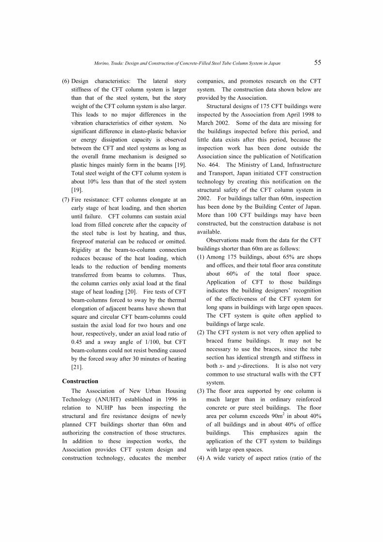
(6) Design characteristics: The lateral story stiffness of the CFT column system is larger than that of the steel system, but the story weight of the CFT column system is also larger. This leads to no major differences in the vibration characteristics of either system. No significant difference in elasto-plastic behavior or energy dissipation capacity is observed between the CFT and steel systems as long as the overall frame mechanism is designed so plastic hinges mainly form in the beams [19]. Total steel weight of the CFT column system is about 10% less than that of the steel system [19].
(7) Fire resistance: CFT columns elongate at an early stage of heat loading, and then shorten until failure. CFT columns can sustain axial load from filled concrete after the capacity of the steel tube is lost by heating, and thus, fireproof material can be reduced or omitted. Rigidity at the beam-to-column connection reduces because of the heat loading, which leads to the reduction of bending moments transferred from beams to columns. Thus, the column carries only axial load at the final stage of heat loading [20]. Fire tests of CFT beam-columns forced to sway by the thermal elongation of adjacent beams have shown that square and circular CFT beam-columns could sustain the axial load for two hours and one hour, respectively, under an axial load ratio of 0.45 and a sway angle of 1/100, but CFT beam-columns could not resist bending caused by the forced sway after 30 minutes of heating [21].
Construction The Association of New Urban Housing
Technology (ANUHT) established in 1996 in relation to NUHP has been inspecting the structural and fire resistance designs of newly planned CFT buildings shorter than 60m and authorizing the construction of those structures. In addition to these inspection works, the Association provides CFT system design and construction technology, educates the member
companies, and promotes research on the CFT system. The construction data shown below are provided by the Association.
Structural designs of 175 CFT buildings were inspected by the Association from April 1998 to March 2002. Some of the data are missing for the buildings inspected before this period, and little data exists after this period, because the inspection work has been done outside the Association since the publication of Notification No. 464. The Ministry of Land, Infrastructure and Transport, Japan initiated CFT construction technology by creating this notification on the structural safety of the CFT column system in 2002. For buildings taller than 60m, inspection has been done by the Building Center of Japan. More than 100 CFT buildings may have been constructed, but the construction database is not available.
Observations made from the data for the CFT buildings shorter than 60m are as follows: (1) Among 175 buildings, about 65% are shops
and offices, and their total floor area constitute about 60% of the total floor space. Application of CFT to those buildings indicates the building designers’ recognition of the effectiveness of the CFT system for long spans in buildings with large open spaces. The CFT system is quite often applied to buildings of large scale.
(2) The CFT system is not very often applied to braced frame buildings. It may not be necessary to use the braces, since the tube section has identical strength and stiffness in both x- and y-directions. It is also not very common to use structural walls with the CFT system.
(3) The floor area supported by one column is much larger than in ordinary reinforced concrete or pure steel buildings. The floor area per column exceeds 90m2 in about 40% of all buildings and in about 40% of office buildings. This emphasizes again the application of the CFT system to buildings with large open spaces.
(4) A wide variety of aspect ratios (ratio of the
56 Earthquake Engineering and Engineering Seismology, Vol. 4, No. 1
longer distance between two columns to the shorter one in x- and y-directions of a floor plan) of span grids indicates the CFT system’s potential for free planning about the span grid. In the case of office buildings, a rectangular span grid of 8m × 18m is fairly often used, and the aspect ratio exceeds 2.2 (about 40% of cases), while the span grid of shop buildings is fairly close to square (about 50% of cases).
(5) Both square and circular sections are used together in a number of buildings. The size of the tube section often used is between 500 and 700mm in the case of square CFT columns (about 80% of cases), and 500 and 711mm in the case of circular CFT columns (about 65% of cases). Circular tubes (diameter: 400 to 1117mm; diameter-thickness ratio: 16 to 90) are mainly used for buildings with irregular plan grids, and square and rectangular tubes (width: 300 to 950mm; width-thickness ratio: 10 to 54) are used for the case of regular plans. Most tubes are cold-formed, since they are inexpensive and widely available. Box sections built-up by welding are used when the plate becomes thick and/or large ductility is required. Cast-steel tubes are used to simplify the beam-to-column connection. Annealing to remove residual stresses is rarely done in Japan.
(6) Inner or through diaphragms are used in most beam-to-column connections (about 80% of cases). The type of diaphragm used seems to be determined by the plate thicknesses of the column and the beam: the through diaphragm is often employed when the beam flange is thicker than the column skin plate; otherwise, the inner diaphragm is employed. The through diaphragm is usually used for cold- formed tubes and the inner diaphragm for built-up tubes. Inner and through diaphragms have openings with diameters of 200 to 300mm for concrete casting, and several small holes for air passage. The outer diaphragm is used as an easy solution, which ensures compaction of the concrete.
(7) Embedded column bases are the most widely used (about 60% of cases), as they are the most structurally reliable. This trend also indicates that the CFT system is often applied to large-scale buildings. If the building has basement stories, encased column bases are often employed, in which column tube sections are changed to cross-H sections, and CFT columns become concrete encased steel columns in the basement.
(8) The ratio of the column effective length to the column depth is much larger than that in ordinary reinforced concrete or pure steel buildings. This difference indicates the relatively large axial load-carrying capacity of the CFT column.
(9) The design standard strength of steel most often used is 325MPa (about 85% of cases), and that of concrete is 36 and 42MPa (about 65% of cases).
DESIGN OF CFT COLUMN SYSTEM
Design Recommendations The first edition of the AIJ standard for
composite concrete and circular steel tube structures was published in 1967, based on the research carried out in the early 1960’s. This edition was written for three types of circular composite sections: the so-called concrete- encased tube, the CFT and the concrete-encased and filled tube sections. The standard was revised in 1980 to include sections using square tubes. This standard was absorbed into the AIJ standard for composite concrete and steel (SRC) structures in 1987, which now included the formulas to evaluate the ultimate strength of circular and square CFT columns, beam-columns and beam-to-column connections. The English version of this standard is available at AIJ [22]. The newest edition of the SRC Standard of AIJ [1] was published in 2001. This edition increased the upper limit of the design standard strength of normal concrete to 60MPa, and revised several parts of design provisions for the CFT column system, in accordance with the contents of the CFT
Morino, Tsuda: Design and Construction of Concrete-Filled Steel Tube Column System in Japan 57
Recommendations [6] explained below. CFT Recommendations [6] were published by
AIJ in 1997, based on recent research developments on the following topics: (1) Special types of CFT members such as braces and truss members, in addition to compression members, beam-columns and connections; (2) formulas to evaluate deformation capacity of CFT columns and frames; (3) structural characteristics under fire; (4) manufacturing of steel tube and mixture of concrete; (5) analysis of the behavior of CFT columns and frames; and (6) strength formulas used in the world.
The results of investigation carried out under NUHP were published in CFT Reports [23] and have been used for the design of the CFT system. This report is the first document in Japan that measured the strength increase of the confined concrete of circular CFT members and showed formulas to evaluate the deformation capacity. Evaluation of the deformation capacity of CFT beam-columns is needed to calculate the structural characteristic factor Ds used in seismic design. In 1996, those industries that originally joined NUHP established the Association of New Urban Housing Technology (ANUHT). The ANUHT consists of more than 100 member companies involved in CFT building construction and authorizes the structural design of newly planned CFT buildings in accordance with the ANUHT’s CFT Recommendations [24]. Based on ANUHT’s Recommendations, CFT construction technology was initiated in 2002 by the publication of Notification No. 464 by the Ministry of Land, Infrastructure and Transport, Japan, as mentioned before.
The ANUHT Recommendations cover the following design and construction items: (1) strength design of columns and beam-columns; (2) evaluation of deformation capacity of beam- columns; (3) fire-resistant design of beam- columns; (4) production of CFT members including compaction of filled concrete by the centrifugal method; and (5) quality control of materials and construction work.
In the fifth phase of the U.S.-Japan Cooperative
Earthquake Research Program, the CFT investigation produced CFT Guidelines [25]. The Guidelines cover the following topics: (1) flow charts for seismic design based on the conventional method using the structural characteristic factor Ds and the performance-based design method which is specified in the recent revision of the Building Standard Law of Japan; (2) constitutive laws for concrete and steel tube derived from the test results of centrally-loaded stub columns, method of analysis for the moment-curvature relation, method of analysis for the load-deformation relation of a beam-column under combined compression, bending and shear, and the model for the restoring- force characteristics of a beam-column which may be used in the analysis of an overall CFT frame; (3) formulas to evaluate stiffness, ultimate strength and deformation capacity of a CFT beam-column, taking into account the confining and scale effects of concrete, the triaxial state of stress and the local buckling of the steel tube; (4) the stress transfer mechanism of a beam-to-column connection and a mathematical model for the shear force- deformation relation of a connection panel; (5) material, manufacturing and fabrication of a steel tube, concrete mixture and casting; (6) design example using an 11-story office building, written for beginners at designing the CFT column system; and (7) investigation of advantages of the CFT column system by the trial design of 10-, 24- and 40-story CFT frames. Some of the research results that formed the background of these Guidelines are summarized in English in the BRI Research Paper [26].
This section introduces design formulas for CFT members shown in the 2001 edition of the SRC Standard of AIJ [1]. General descriptions are as follows: (1) The design method used in this standard is
basically the allowable stress design supported by the elastic analysis of the structures. In earthquake-resistant design, it must be proved that the ultimate lateral load-resisting capacity of the allowable stress designed buildings is larger than the required value to resist a severe earthquake. The design loads and the
58 Earthquake Engineering and Engineering Seismology, Vol. 4, No. 1
allowable stresses of materials are specified by the Building Standard Law and AIJ standards.
(2) The specified yield stress of steel tubes ranges from 235MPa (215 if plate thickness t > 40mm) to 355MPa (335 if t > 40mm) in accordance with several steel grades which contain high-strength steel SM520 and centrifugal high-strength cast steel tube SCW520CF.
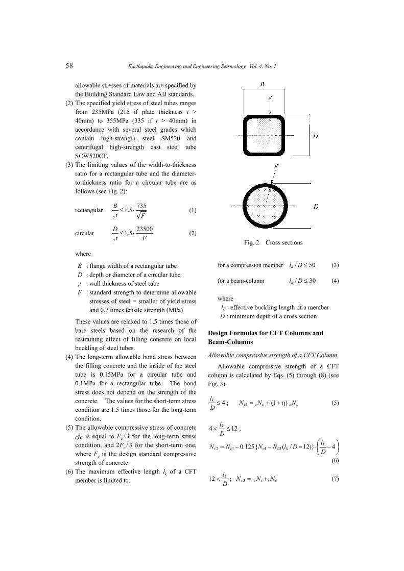
(3) The limiting values of the width-to-thickness ratio for a rectangular tube and the diameter- to-thickness ratio for a circular tube are as follows (see Fig. 2):
rectangular Ft
Bs
7355.1 ⋅≤ (1)
circular Ft
Ds
235005.1 ⋅≤ (2)
where
B : flange width of a rectangular tube D : depth or diameter of a circular tube st : wall thickness of steel tube F : standard strength to determine allowable
stresses of steel = smaller of yield stress and 0.7 times tensile strength (MPa)
These values are relaxed to 1.5 times those of bare steels based on the research of the restraining effect of filling concrete on local buckling of steel tubes.
(4) The long-term allowable bond stress between the filling concrete and the inside of the steel tube is 0.15MPa for a circular tube and 0.1MPa for a rectangular tube. The bond stress does not depend on the strength of the concrete. The values for the short-term stress condition are 1.5 times those for the long-term condition.
(5) The allowable compressive stress of concrete cfc is equal to Fc / 3 for the long-term stress condition, and 2Fc / 3 for the short-term one, where Fc is the design standard compressive strength of concrete.
(6) The maximum effective length lk of a CFT member is limited to:
Fig. 2 Cross sections
for a compression member (3) 50/ ≤Dlk
for a beam-column (4) 30/ ≤Dlk
where kl : effective buckling length of a member
D : minimum depth of a cross section
Design Formulas for CFT Columns and Beam-Columns
Allowable compressive strength of a CFT Column
Allowable compressive strength of a CFT column is calculated by Eqs. (5) through (8) (see Fig. 3).
4≤Dlk ; (5) csccc NNN )1(1 η++=
124 ≤<Dlk ;
−⋅=−−= 4)}12/({125.0 3112 D
lDlNNNN kkcccc
(6)
Dlk<12 ; (7) csccc NNN +=3
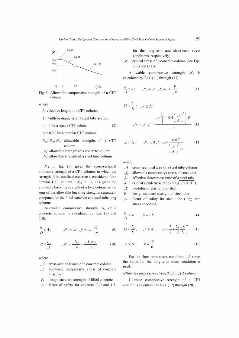
Morino, Tsuda: Design and Construction of Concrete-Filled Steel Tube Column System in Japan 59
Fig. 3 Allowable compressive strength of a CFT
column
where
lk: effective length of a CFT column
D: width or diameter of a steel tube section
η = 0 for a square CFT column (8)
η = 0.27 for a circular CFT column
Nc1, Nc2, Nc3 : allowable strengths of a CFT column
cNc: allowable strength of a concrete column sNc: allowable strength of a steel tube column
Nc1 in Eq. (5) gives the cross-sectional allowable strength of a CFT column, in which the strength of the confined concrete is considered for a circular CFT column. Nc3 in Eq. (7) gives the allowable buckling strength of a long column as the sum of the allowable buckling strengths separately computed for the filled-concrete and steel tube long columns.
Allowable compressive strength cNc of a concrete column is calculated by Eqs. (9) and (10).
4≤Dlk ;
ν⋅=⋅=
c
ccccccc
FAfAN (9)
Dlk<12 ;
νσ⋅
=ν
=c
crcc
c
crcc
ANNc (10) >λs
where : cross-sectional area of a concrete column Ac
c : allowable compressive stress of concrete (=
cfνccF / )
: design standard strength of filled concrete cF : factor of safety for concrete (3.0 and 1.5,
for the long-term and short-term stress conditions, respectively)
νc
crc σ : critical stress of a concrete column (see Eqs. (30) and (31))
Allowable compressive strength sNc is calculated by Eqs. (11) through (13).
4≤Dlk ;
ν⋅=⋅=
sscsscs
FAfAN (11)
Dlk<12 ; Λ≤λs ;
ν
Λλ
−
=⋅=s
ss
csscs
FA
fAN
2
4.01
(12)
Λ>λs ;
ν
Λλ
⋅=⋅=
ss
scsscsFAfAN 2
6.0 (13)
where As : cross-sectional area of a steel tube column
cs f : allowable compressive stress of steel tube λs : effective slenderness ratio of a steel tube
Λ : critical slenderness ratio (= FEs 6.0/π ) Es : modulus of elasticity of steel
F : design standard strength of steel tube νs : factor of safety for steel tube (long-term
stress condition)
4≤Dlk ; (14) 5.1=νs
Dlk<12 ; ; Λ≤λs
2
32
23
Λλ
+=ν ss (15)
Λ ; 6
13=νs (16)
For the short-term stress condition, 1.5 times the value for the long-term stress condition is used.
Ultimate compressive strength of a CFT column
Ultimate compressive strength of a CFT column is calculated by Eqs. (17) through (20).
60 Earthquake Engineering and Engineering Seismology, Vol. 4, No. 1
4≤Dlk ; (17) cuscuccu NNN )1(1 η++=
124 ≤<Dlk ;
{ }
−⋅=−−= 4)12/(125.0 311
2
DlDlNNN
N
kkcucucu
cu
(18)
Dlk<12 ; (19) crscrccu NNN +=3
where lk : effective length of a CFT column D : width or diameter of a steel tube section η = 0 for a square CFT column (20) η = 0.27 for a circular CFT column Ncu1, Ncu2, Ncu3 : ultimate strengths of a CFT column cNcu : ultimate strength of a concrete column sNcu : ultimate strength of a steel tube column cNcr : buckling strength of a concrete column sNcr : buckling strength of a steel tube column
Ncu1 in Eq. (17) gives the cross-sectional strength of a CFT column, in which the strength of confined concrete is considered for a circular CFT column.
Derivation of Eq. (17) is as follows. Referring to Fig. 4, when the CFT section is under the ultimate compression force Ncu1 , the concrete in a circular CFT section is subjected to axial stress cσcB and lateral pressure σr, and the steel tube is subjected to axial stress sσz and ring tension stress sσθ, Ncu1 is first given by
ZsscBcccu AAN σ⋅+σ⋅=1 (21)
The axial stress of concrete considering the confining effect cσcB is given by
rBccBc k σ⋅+σ=σ (22)
where k denotes the confining factor. Equilibrium of σr and sσr gives
θσ⋅=σ⋅− ssrs ttD 2)2( ; θσ⋅−
=σ ss
sr tD
t2
2 (23)
Substituting Eqs. (22) and (23) into Eq. (21) leads to
yssZssyssBcccu AAAAN σ⋅−σ⋅+σ⋅+σ⋅=1
Fig. 4 Confined effect for a circular CFT
column
θσ−
⋅⋅ ss
sc tD
tkA2
2+ (24)
The ratio of the cross-sectional area of concrete to that of steel tube is approximately given by
ttDtD
AA
ss
s
s
c
⋅−π−π
=}2/){(2
}2/)2{( 2 (25)
Substituting Eq. (25) into Eq. (24) leads to
yssBcccu AAN σ⋅+σ⋅=1
})(2
21{tDtDkA
s
s
ys
s
ys
zsyss
−−
⋅σσ
⋅+−σσ
σ⋅+ θ (26)
Denoting cNcu = cA・cσcB, sNcu = sA・sσy and
)(221tDtDk
ys
s
ys
zs
−−
⋅σσ
⋅+−σσ
=η θ (27)
In Eq. (27), the value sσθ /sσy = 0.19 was obtained empirically by the regression analysis of the test data. Assuming the confining factor k = 4.1 and the diameter-to-thickness ratio D / t = 50, then the value η became 0.27. The expression of Ncu1 is finally given as Eq. (17).
Ncu3 in Eq. (19) gives the buckling strength of a long column as the sum of the buckling strengths separately computed for the filled- concrete and steel tube long columns. The
Morino, Tsuda: Design and Construction of Concrete-Filled Steel Tube Column System in Japan 61
accuracy of Eq. (19) compared with the tangent modulus load of the CFT column is discussed in Ref. [3].
Ultimate compressive strength cNcu and buckling strength cNcr of a concrete column are calculated by Eqs. (28) and (29), respectively.
cucccuc FrAN ⋅⋅= (28)
crcccrc AN σ⋅= (29)
where
: cross-sectional area of a concrete column Ac
: design standard strength of filled concrete
cF
: critical stress of a concrete column crc σuc r = 0.85: reduction factor for concrete strength
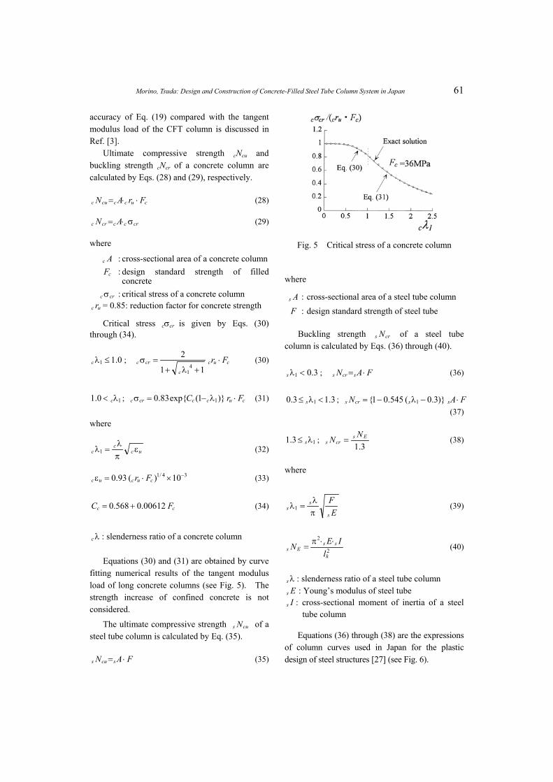
Critical stress cσcr is given by Eqs. (30) through (34).
0.11 ≤λc ; cuc
c
crc Fr ⋅+λ+
=σ11
24
1
(30)
10.1 λ< c ; (31) cucccrc FrC ⋅λ−=σ )}1(exp{83.0 1
where
ucc
c επλ
=λ1 (32) 1
34/1 10)(93.0 −×⋅=ε cucuc Fr (33)
cc FC 00612.0568.0 += (34) Fs
sλ
=
λc : slenderness ratio of a concrete column
Equations (30) and (31) are obtained by curve fitting numerical results of the tangent modulus load of long concrete columns (see Fig. 5). The strength increase of confined concrete is not considered.
The ultimate compressive strength of a steel tube column is calculated by Eq. (35).
cus N
FAN scus ⋅= (35)
Fig. 5 Critical stress of a concrete column
where
: cross-sectional area of a steel tube column As
F : design standard strength of steel tube
Buckling strength of a steel tube column is calculated by Eqs. (36) through (40).
crs N
3.01 <λs ; (36) FAN scrs ⋅=
3.13.0 1 <λ≤ s ; FAN sscrs ⋅−λ−= )}3.0(545.01{ 1
(37)
13.1 λ≤ s ; 3.Es
crsNN = (38)
where
Esπλ1 (39)
2
2
k
ssEs
lIEN ⋅⋅π
= (40)
λs : slenderness ratio of a steel tube column Es : Young’s modulus of steel tube Is : cross-sectional moment of inertia of a steel
tube column
Equations (36) through (38) are the expressions of column curves used in Japan for the plastic design of steel structures [27] (see Fig. 6).

62 Earthquake Engineering and Engineering Seismology, Vol. 4, No. 1
Fig. 6 Allowable and buckling strength of a steel
tube column
Allowable bending strength of a CFT beam-column
A beam-column not longer than 12 times the width or diameter of the steel tube section has a strength stipulated by Eqs. (41) and (42) for the allowable state.
ccNN ≤ ; (41) NN c=
MMM cs +≤ 0
ccNN > ; (42) NNN scc +≤
MM s=
where M : design bending moment N : design compressive force cNc : allowable compressive strength of filled
concrete portion sM0 : allowable bending strength of steel tube
subjected to bending alone cM : allowable bending strength of filled
concrete portion cN : allowable compressive strength of filled
concrete portion sM : allowable bending strength of steel portion sN : allowable compressive strength of steel
portion
The strengths appearing on the right-hand sides of Eqs. (41) and (42) are given as follows:
For a square CFT beam-column:
0< ; 11 ≤nx cccn
c fDxN ⋅= 21
2 (43)
cccnn
c fDxxM ⋅−
= 311
12)23(
(44)
1< ; 1nx cccn
c fDx
N ⋅
−= 2
1211 (45)
cccn
c fDx
M ⋅= 3
1121
(46)
For a circular CFT beam-column:
0 < ; 11 ≤nx=Nc cnnnn }cos3/)cos2({sin 2 θθ−θ+θ
)8(/ 12
ncc xfD ⋅⋅ (47)
=Mc
)64(/}3/)2/5(cos2sin{ 132
ncccnnn xfD−θθ+θ (48)
11 nx< ; (49) 4/)}2(/11{ 21 cccnc fDxN ⋅−π=
)64(/ 13
ncccc xfDM ⋅π= (50)
where
Dxxc
nn =1 (51)
)21(cos 11
nn x−=θ − (52)
cD: width or diameter of a concrete section xn : position parameter of neutral axis sN and sM in Eq. (42) must satisfy Eq. (53).
css
s
s
s fZM
AN
=+ (53)
sZ: section modulus of steel portion sfc: allowable tensile stress of steel tube
Axial and bending strengths carried by concrete and steel tube beam-columns at the allowable state are calculated by Eqs. (43) ~ (50) and (53), respectively, based on the stress distributions shown in Fig. 7 with the neutral axis at the distance xn from the extreme compression fiber. The strength increase of confined concrete is not considered. cM-cN relations are shown in Fig. 8.
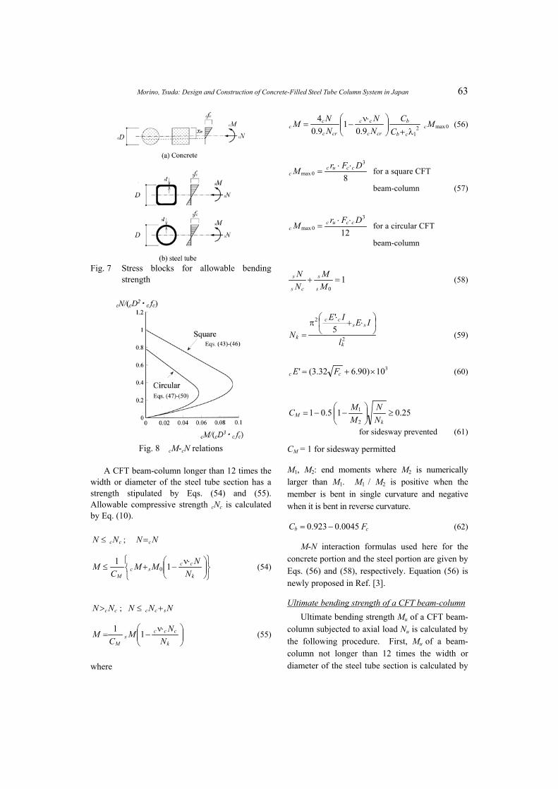
Morino, Tsuda: Design and Construction of Concrete-Filled Steel Tube Column System in Japan 63
Fig. 7 Stress blocks for allowable bending
strength
Fig. 8 cM-cN relations
A CFT beam-column longer than 12 times the width or diameter of the steel tube section has a strength stipulated by Eqs. (54) and (55). Allowable compressive strength cNc is calculated by Eq. (10).
ccNN ≤ ; NN c=
⋅ν−+≤
k
ccsc
M NNMM
CM 11
0 (54)
ccNN > ; NNN scc +≤
⋅ν−=
k
cccs
M NNM
CM 11
(55)
where
0max219.0
19.04 M
CC
NN
NNM c
cb
b
crc
cc
crc
cc
λ+
⋅ν−= (56)
8
3
0maxDFrM ccuc
c⋅⋅
= for a square CFT
beam-column (57)
12
3
0maxDFrM ccuc
c⋅⋅
= for a circular CFT
beam-column
10
=+MM
NN
s
s
cs
s (58)
2
2
5'
k
sscc
kl
IEIE
N
⋅+
⋅π
= (59)
310)90.632.3(' ×+= cc FE (60)
25.015.012
1 ≥
−−=
kM N
NMMC
for sidesway prevented (61)
CM = 1 for sidesway permitted
M1, M2: end moments where M2 is numerically larger than M1. M1 / M2 is positive when the member is bent in single curvature and negative when it is bent in reverse curvature.
cb FC 0045.0923.0 −= (62)
M-N interaction formulas used here for the concrete portion and the steel portion are given by Eqs. (56) and (58), respectively. Equation (56) is newly proposed in Ref. [3].
Ultimate bending strength of a CFT beam-column Ultimate bending strength Mu of a CFT beam-
column subjected to axial load Nu is calculated by the following procedure. First, Mu
of a beam- column not longer than 12 times the width or diameter of the steel tube section is calculated by
64 Earthquake Engineering and Engineering Seismology, Vol. 4, No. 1
Eqs. (63) and (64).
usucu NNN += (63)
usucu MMM += (64)
The strengths appearing on the right side of Eqs. (63) and (64) are given as follows:
For a square CFT beam-column:
cuccnuc FrDxN ⋅⋅⋅= 21 (65)
cuccnnuc FrDxxM ⋅⋅⋅−= 311)1(
21
(66)
ysscnus tDxN σ⋅⋅−= 21 )12(2 (67)
ysscnns
us tDxxDDtM σ⋅
⋅−+
−= 2
112 )1(21 (68)
For a circular CFT beam-column:
4)cossin(
2cBcc
nnnucDN σ⋅
θθ−θ= (69)
12sin
33 cBcc
nucDM σ⋅
θ= (70)
{ } ysss
nnus tDDtN σ⋅⋅
−π−θβ+θβ= 1)(21 (71)
yss
s
nus tDDt
M σ⋅⋅
−
θβ+β= 2
2
21 2
1sin)( (72)
where
Dxxc
nn =1 (73)
)21(cos 11
nn x−=θ − (74)
tDt
Frs
ysscuccBc 2
56.1−
σ⋅+⋅=σ (75)
89.01 =β , β (76) 08.12 =
cD : width or diameter of a concrete section : thickness of a steel tube section ts
: position parameter of neutral axis nx s : yield stress of steel tube yσ
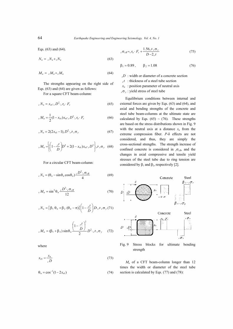
Equilibrium conditions between internal and external forces are given by Eqs. (63) and (64), and axial and bending strengths of the concrete and steel tube beam-columns at the ultimate state are calculated by Eqs. (65) ~ (76). These strengths are based on the stress distributions shown in Fig. 9 with the neutral axis at a distance xn from the extreme compression fiber. P-δ effects are not considered, and thus, they are simply the cross-sectional strengths. The strength increase of confined concrete is considered in cσcB, and the changes in axial compressive and tensile yield stresses of the steel tube due to ring tension are considered by β1 and β2, respectively [2].
Fig. 9 Stress blocks for ultimate bending
strength
Mu of a CFT beam-column longer than 12 times the width or diameter of the steel tube section is calculated by Eqs. (77) and (78):
Morino, Tsuda: Design and Construction of Concrete-Filled Steel Tube Column System in Japan 65
crcu NN ≤ ;
−+=
k
uusuc
Mu N
NMMC
M 110 (77)
crcu NN > ;
−=
k
crcus
Mu N
NMC
M 11 (78)
where
max9.01
9.04 M
NN
NNM c
crc
u
crc
uuc
−= (79)
0max21
max MC
CM ccb
bc
λ+= (80)
8
3
0maxDFrM ccuc
c⋅⋅
= for a square CFT
beam-column (81)
12
3
0maxDFrM ccuc
c⋅⋅
= for a circular CFT
beam-column
11
=
−−
+−
uosEs
crcu
us
crs
crcu
MN
NNM
NNN
(82)
sMu0: full plastic moment of a steel tube section
2
2
5'
k
sscc
k l
IEIE
N
⋅+
⋅π
= (83)
310)90.632.3(' ×+= cc FE (84)
25.015.012
1 ≥
−−=
k
uM N
NMMC for sidesway
prevented (85)
1=MC for sidesway permitted
M1, M2: end moments where M2 is numerically larger than M1. M1 / M2 is positive when the member is bent in single curvature and negative when it is bent in reverse curvature.
cb FC 0045.0923.0 −= (86)
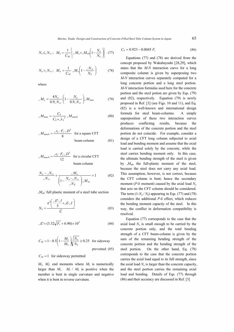
Equations (77) and (78) are derived from the concept proposed by Wakabayashi [28,29], which states that the M-N interaction curve for a long composite column is given by superposing two M-N interaction curves separately computed for a long concrete portion and a long steel portion. M-N interaction formulas used here for the concrete portion and the steel potion are given by Eqs. (79) and (82), respectively. Equation (79) is newly proposed in Ref. [3] (see Figs. 10 and 11), and Eq. (82) is a well-known and international design formula for steel beam-columns. A simple superposition of these two interaction curves produces conflicting results, because the deformations of the concrete portion and the steel portion do not coincide. For example, consider a design of a CFT long column subjected to axial load and bending moment and assume that the axial load is carried solely by the concrete, while the steel carries bending moment only. In this case, the ultimate bending strength of the steel is given by sMu0, the full-plastic moment of the steel, because the steel does not carry any axial load. This assumption, however, is not correct, because the CFT column is bent; hence the secondary moment (P-δ moment) caused by the axial load Nu that acts on the CFT column should be considered. The term (1-Nu / Nk) appearing in Eqs. (77) and (78) considers the additional P-δ effect, which reduces the bending moment capacity of the steel. In this way, the conflict in deformation compatibility is resolved.
Equation (77) corresponds to the case that the axial load Nu is small enough to be carried by the concrete portion only, and the total bending strength of a CFT beam-column is given by the sum of the remaining bending strength of the concrete portion and the bending strength of the steel portion. On the other hand, Eq. (78) corresponds to the case that the concrete portion carries the axial load equal to its full strength, since the axial load Nu is larger than the concrete capacity, and the steel portion carries the remaining axial load and bending. Details of Eqs. (77) through (86) and their accuracy are discussed in Ref. [3]
66 Earthquake Engineering and Engineering Seismology, Vol. 4, No. 1
Fig. 10 cMu-cNu relations
Fig. 11 cMmax-cλ1 relations
Biaxial bending A beam-column subjected to combined axial
force and biaxial bending moments has a strength stipulated by Eq. (87) for the allowable state.
NNN cs +=
xcxsx MMM +≤ (87) Qs
ycysy MMM +≤
where N : design compressive force Mx : design bending moment about the x-axis My : design bending moment about the y-axis sMx : allowable flexural strength about the x-axis
of steel tube sMy : allowable flexural strength about the y-axis
of steel tube cMx : allowable flexural strength about the x-axis
of filled concrete portion cMy : allowable flexural strength about the y-axis
of filled concrete portion
Limiting value of design compressive force The compression load on the column in rigid
frames shall be limited to a value given by Eq. (88) in which seismic horizontal loading guarantees a sufficient flexural deformation capacity at least 0.01rad of the rotation angle of the column member.
32
3csscc
lfAFAN ⋅
+⋅
= (88)
The same limit is specified for a concrete encased steel (SRC) column.
Design formulas for shear force When an SRC member is subjected to
repeated shear load, the bond between the steel and concrete is broken. Thus, the shear design is carried out in such a way that steel and reinforced concrete portions resist the shear separately without expecting any bond strength between the steel and concrete. In the case of a concrete-filled tubular column, the check for the shear strength of the core concrete is not necessary for both long- and short-term stress conditions, since shear failure is unlikely to occur in the core concrete.
Calculation for short-term stress condition is as given by Eq. (89).
asds QQ ≤ (89)
where
s : design shear force for a steel tube
(=
dQ
MM d )
sMd : design bending moment for steel portion M : design bending moment Q : design shear force sQa : allowable shear strength of steel portion
(= sss fA
⋅2
)
sfs : allowable shear stress of steel (=ν⋅ s
F3
)
Ultimate shear strength Qu of a CFT beam-column is calculated by Eq. (90).
usucu QQQ += (90)
Morino, Tsuda: Design and Construction of Concrete-Filled Steel Tube Column System in Japan 67
where
cQu : ultimate shear strength of concrete portion
(='h
M ucΣ )
uc MΣ : sum of ultimate flexural strength of filled concrete portion at the top and bottom of a column
h′: clear height of column
For a rectangular CFT beam-column:
⋅⋅⋅
−⋅=cuccc
cuc FrDbNDNM
** 1
21
(91)
For a circular CFT beam-column:
)cossin(4
2*
nnncucc FrDN θ⋅θ−θ
⋅⋅= (92)
ncucc
ucFrDM θ
⋅⋅= 3
3
sin12
(93)
N* : when Nu ≤ cN, N* = Nu, when Nu > cN, N* = cNc
: ultimate shear strength of the steel portion ( )
us Q),min( bussus QQ=
s : ultimate shear strength controlled by shear
failure of the steel portion (
suQ
32yss A σ
⋅= )
s : ultimate shear strength controlled by flexural yielding of steel portion
(
buQ
'hMusΣ= )
h′ : clear story height sMu : ultimate bending strength determined by
Eqs. (68), (72) or (82)
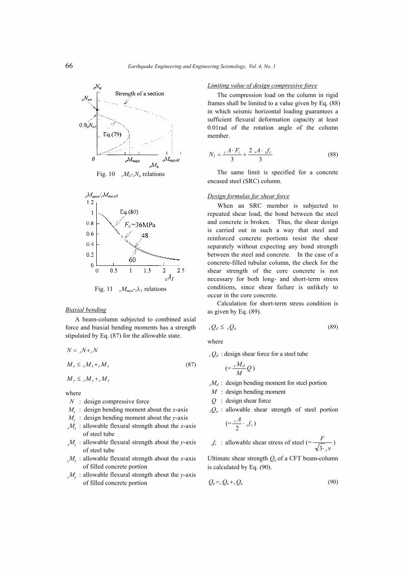
Bond between steel tube and concrete When a part of the shear force in the steel
beams is expected to be transmitted to the filling concrete as a compression force, the bond stress between the concrete and steel tube must be checked. It may be considered that the bond stress, uniformly distributed between center points of the upper and lower story columns (i.e., between point A and D in Fig. 12), is available for the axial force transfer. The check for the bond is given by Eq. (94).
asic flN ⋅⋅ψ≤∆ (94)
where
: axial force transferred to the column from ith floor beams
ic N∆
ψ : peripheral length l : length between center points of the
upper and lower story columns sfa : allowable bond stress of steel tube
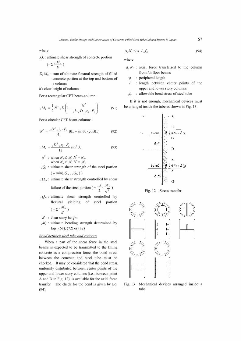
If it is not enough, mechanical devices must be arranged inside the tube as shown in Fig. 13.
Fig. 12 Stress transfer
Fig. 13 Mechanical devices arranged inside a tube
68 Earthquake Engineering and Engineering Seismology, Vol. 4, No. 1
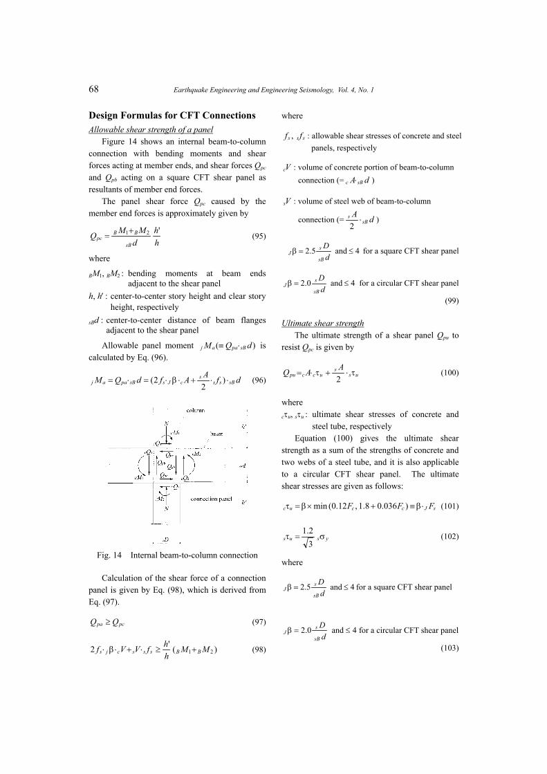
Design Formulas for CFT Connections Allowable shear strength of a panel
Figure 14 shows an internal beam-to-column connection with bending moments and shear forces acting at member ends, and shear forces Qpc and Qpb acting on a square CFT shear panel as resultants of member end forces.
The panel shear force Qpc caused by the member end forces is approximately given by
hh
dMMQ
sB
BBpc
'21+= (95)
where
BM1, BM2 : bending moments at beam ends adjacent to the shear panel
h, h′ : center-to-center story height and clear story height, respectively
sBd : center-to-center distance of beam flanges adjacent to the shear panel
Allowable panel moment is calculated by Eq. (96).
)( dQM sBpaaj ⋅≡
dfAAfdQM sBsss
cJssBpaaj ⋅⋅+⋅β⋅=⋅= )2
2( (96)
Fig. 14 Internal beam-to-column connection
Calculation of the shear force of a connection panel is given by Eq. (98), which is derived from Eq. (97).
pcpa QQ ≥ (97) Ds
)('2 21 MMhhfVVf BBssscjs +≥⋅+⋅β⋅ (98)
where
sss ff , : allowable shear stresses of concrete and steel panels, respectively
Vc : volume of concrete portion of beam-to-column connection (= c ) dA sB⋅
Vs : volume of steel web of beam-to-column
connection (= dAsB
s ⋅2
)
4and5.2 ≤=βd
DsB
sJ for a square CFT shear panel
4and0.2 ≤=βd
DsB
sJ for a circular CFT shear panel
(99)
Ultimate shear strength The ultimate strength of a shear panel Qpu to
resist Qpc is given by
uss
uccpuAAQ τ⋅+τ⋅=
2 (100)
where cτu, sτu : ultimate shear stresses of concrete and
steel tube, respectively Equation (100) gives the ultimate shear
strength as a sum of the strengths of concrete and two webs of a steel tube, and it is also applicable to a circular CFT shear panel. The ultimate shear stresses are given as follows:
sJccuc FFF ⋅β≡+×β=τ )036.08.1,12.0(min (101)
ysus σ=τ32.1
(102)
where
4and5.2 ≤=βd
DsB
sJ for a square CFT shear panel
4and0.2 ≤=βdsB
J for a circular CFT shear panel
(103)
Morino, Tsuda: Design and Construction of Concrete-Filled Steel Tube Column System in Japan 69
sBd : center-to-center distance of beam flanges adjacent to the shear panel
sD : diameter of steel tube
The shear force acting on a concrete panel may actually be resisted by the horizontal force carried by a diagonal strut forming in the shear panel, and it becomes larger as the inclination angle of the strut becomes smaller (i.e., sD /sBd
becomes larger). The parameter β considers this effect.
Ultimate panel moment is calculated by Eq. (104).
)( dQM sBpuuj ⋅≡
32.1 ys
sJsJcuj VFVMσ
⋅+β⋅⋅= (104) (P =
where cV : volume of concrete portion of a beam-to-
column connection (= ) dA sBc ⋅sV : volume of steel web of a beam-to-column
connection (= dAsB
s ⋅2
)
Checking the transmission in bending moment between a bare steel beam and a CFT column at the connection is not necessary if Eq. (105) is satisfied. If it is not satisfied, smooth transfer of forces must be assumed by an adequate method.
5.24.0 ≤≤asB
asC
MM
(105)
where asBasC MM , : sum of allowable flexural moments
of all columns and all beams adjacent to the connection, respectively
Tensile strength of diaphragms
The diaphragm steel plate is necessary in order to transfer the stresses caused in beams and columns and to prevent excessive local deformation in a steel tubular column (see Fig. 15). The diaphragm plate may be designed by considering the effect of the filled concrete and the steel tube wall, each restraining the deformation of the other. Commentary on SRC Standard [1] gives design formulas for several
types of connections, as shown in Figs. 16 and 17. Ultimate strength Pu of diaphragms subjected
to tension from the adjacent beam flange is given by the following formulas:
For an outer diaphragms of a square CFT connection (Fig. 16(a)):
++= 213
4)4(242.1 FthFtttP sssu (106)
For a through diaphragm of a square CFT connection (Fig. 16(b)):
222)242.1 F
dtB
dhDf
sffsu −+ (107)
For an outer diaphragm of a circular CFT connection (Figs. 17(a), 17(b)):
+
+= 188.063.053.142.1 FttDtDB
P sf
u
+ (108)
277.1 Fth ss
where
hs : width of a diaphragm at A-A section ts : thickness of a diaphragm Bf : width of a beam flange df : diameter of an opening for concrete
casting F , : design standard strengths of steel tube
and diaphragm, respectively 1 2F
Fig. 15 Stress around the connection and local deformation
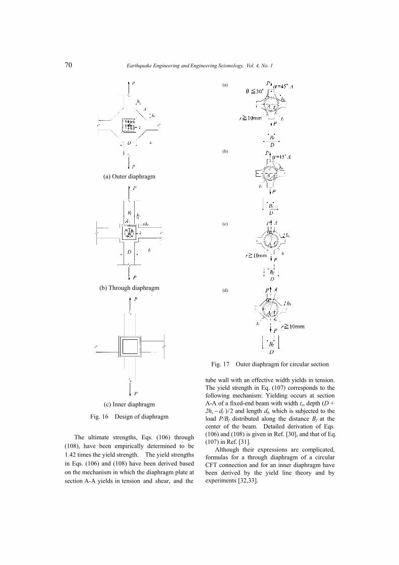
70 Earthquake Engineering and Engineering Seismology, Vol. 4, No. 1
(a) Outer diaphragm
(b) Through diaphragm
(c) Inner diaphragm
Fig. 16 Design of diaphragm
The ultimate strengths, Eqs. (106) through (108), have been empirically determined to be 1.42 times the yield strength. The yield strengths in Eqs. (106) and (108) have been derived based on the mechanism in which the diaphragm plate at section A-A yields in tension and shear, and the
(a)
(b)
(c)
(d)
Fig. 17 Outer diaphragm for circular section
tube wall with an effective width yields in tension. The yield strength in Eq. (107) corresponds to the following mechanism: Yielding occurs at section A-A of a fixed-end beam with width ts, depth (D + 2hs − df ) / 2 and length df, which is subjected to the load P/Bf distributed along the distance Bf at the center of the beam. Detailed derivation of Eqs. (106) and (108) is given in Ref. [30], and that of Eq. (107) in Ref. [31].
Although their expressions are complicated, formulas for a through diaphragm of a circular CFT connection and for an inner diaphragm have been derived by the yield line theory and by experiments [32,33].
Morino, Tsuda: Design and Construction of Concrete-Filled Steel Tube Column System in Japan 71
CONCLUDING REMARKS
A rational design method for the CFT column system has been established through extensive research by the Architectural Institute of Japan, the New Urban Housing Project and the U.S.-Japan Cooperative Earthquake Research Program, and several design standards, recommendations and guidelines are available [1,22~26]. Enabling an engineer to design a CFT column system freely requires, (1) a design method for a CFT beam- column using higher strength material, (2) formulas to evaluate deformation capacity of both short and slender CFT beam-columns, (3) the restoring force characteristic of a CFT beam-column and connection, and (4) the limiting value of design compressive force taking structural properties of a CFT column into consideration.
More than 40 CFT buildings have been constructed each of the last five years in Japan. CFT structures are mainly used in shop, office and hotel construction. The characteristics of CFT make the system especially applicable to high-rise and long-span structures, because the system’s construction efficiency saves construction cost, time, and manpower. Trial designs of unbraced frames have shown that the structural characteristics of the CFT and steel systems are almost the same, but the total steel consumption of the CFT system for the entire building is about 10% less than that of the steel system.
The deformation at which a CFT beam-column reaches maximum strength is fairly large: some of the specimens attained the maximum strength after the chord rotation angle became larger than 1/100. In addition, it becomes known that the dynamic characteristics of the CFT system are almost the same as those of the steel system. These facts indicate that the CFT system is not very stiff against lateral loads, and thus, further investigation of structural systems other than moment frames is now needed in order to utilize the large axial load-carrying capacity of the CFT column more effectively. Other lateral resisting systems may include braced frames or a combination of reinforced concrete shear walls and CFT columns in which CFT columns carry most of the vertical load.
The weak point of the CFT system is the connections: beam-to-column connections, brace- to-frame connections and column bases. The outer diaphragm type of beam-to-column
connection is sometimes avoided because the diaphragm sticking outward disturbs the arrangement of curtain walls, so the through type of connection is most popular. The through diaphragm type of connection is fabricated by first cutting the steel tube into three pieces and then welding them together with two diaphragms. Therefore, the type requires a large amount of welding. Moreover, if the heights of beams coming into a connection are different, or a brace is attached to a CFT column with a gusset plate and diaphragms, filled concrete in the tube is separated into more layers than in an ordinary beam-to-column connection. These cases require a greater amount of welding and increase the possibility of defects in cast concrete. Therefore, development of a new type of connection without cutting the column body and without using welding is needed. A possible alternative is a connection that uses long bolts or a steel tube whose wall thickness is partly increased at the connection. Some research work has been done on these new types, but design formulas are not yet well prepared.
The CFT column base is usually designed the same way as an ordinary steel column base without any special consideration. For example, in the design of a bare type CFT column base, it is assumed that total axial load and bending moment are resisted by the tensile strength of the anchor bolts, bending strength of base plates, and the bearing strength of the concrete foundation. The shear force is resisted by the friction between the base plate and the concrete, and the shear strength of the anchor bolts. However, some part of the compressive axial load may be directly transferred to the foundation concrete, and the concrete portion in the CFT column may be effective in resisting shear if it is continuous to the foundation concrete through an opening in the base plate. Therefore, a more suitable design method to utilize the CFT characteristics may be possible. Investigation on this subject has just started.
Most design engineers have treated the CFT system as an alternative to the steel system, trying to cut the cost by reducing the steel consumption. However, it is also possible to look at the CFT system as an alternative to the reinforced concrete system. In addition to structural advantages such as high strength and high ductility, the CFT system has the following ecological advantages over the RC system: neither formwork nor reinforcing bars
72 Earthquake Engineering and Engineering Seismology, Vol. 4, No. 1
are needed, which leads to very clean construction sites; steel tube peels from the filled concrete and is reused when the building is pulled down; filled concrete is of high quality and is easily crushed because it does not contain reinforcing bars, and therefore is also reusable as aggregates. An unanswered question regarding the effectiveness of the CFT system is its cost performance, and thus, investigation by trial design is needed to compare the advantages and disadvantages of the CFT system with the RC system, including life cycle assessment.
ACKNOWLEDGMENTS
Construction data presented in Chapter 2 were generously provided by the Association of New Urban Housing Technology. The author wishes to express sincere gratitude to the Association.
REFERENCES
1. Architectural Institute of Japan (AIJ). (2001). Standard for Structural Calculation of Steel Reinforced Concrete Structures, 5th Ed. (in Japanese).
2. Sakino, K., Ninakawa, T., Nakahara, H. and Morino, S. (1998). “Experimental studies and design recommendations on CFT Columns— U.S.-Japan Cooperative Earthquake Research Program,” Proceedings, Structural Engineers World Congress, San Francisco, CD Rom, Paper No. T169-3.
3. Tsuda, K., Matsui, C. and Fujinaga, T. (2000). “Simplified Design Formula of Slender Concrete-Filled Steel Tubular Beam-Columns, Proceedings, 6th ASCCS Conference on Composite and Hybrid Structures, Los Angeles, Vol. 1, pp. 457−464.
4. Nakahara, H., Sakino, K. and Inai, E. (1998). “Analytical model for compressive behavior of concrete filled square steel tubular columns,” Transactions of Japan Concrete Institute, Vol. 20, pp. 171−178.
5. Yamamoto, T., Kawaguchi, J. and Morino, S. (2002). “Experimental study of the size effect on the behavior of concrete filled circular steel tube columns under axial compression,” Journal of Structural and Construction Engineering, Transactions of AIJ, No. 561, pp.
237−244 (in Japanese). 6. Architectural Institute of Japan (AIJ). (1997).
Recommendations for Design and Construction of Concrete Filled Steel Tubular Structures (in Japanese).
7. Nakahara, H. and Sakino, K. (2000). “Flexural behavior of concrete filled square steel tubular beam-columns, Proc. 12th WCEE, Auckland,” CD-Rom, No. 1923.
8. Sakino, K., Inai, E. and Nakahara, H. (1998). “Tests and analysis on elasto-plastic behavior of CFT beam-columns—U.S.-Japan cooperative earthquake research program,” Proc. 5th Pacific Structural Steel Conference, Seoul, Vol. 2, pp. 901−906.
9. Inai, E., Noguchi, T. Mori, O. and Fujimoto, T. (2000). “Deformation capacity and hysteretic model of concrete-filled steel tubular beam- columns,” Proc. 6th ASCCS Conference on Composite and Hybrid Structures, Los Angeles, Vol. 1, pp. 605−612.
10. Kawaguchi, J., Ueda, M. and Morino, S. (1994). “Elasto-Plastic Behavior of Concrete-Filled Steel Tubular Frames,” Journal of Constructional Steel, Vol. 2, pp. 25−32 (in Japanese).
11. Fujimoto, T., Inai, E., Kai, M., Mori, K., Mori, O. and Nishiyama, I. (2000). “Behavior of beam-to-column connection of CFT column system,” Proc. 12th WCEE, Auckland, CD-ROM, No. 2197.
12. Fukumoto, T. and Morita, K. (2000). “Elasto plastic behavior of steel beam to square concrete filled steel tube (CFT) column connections,” Proc. 6th ASCCS Conference on Composite and Hybrid Structures, Los Angeles, Vol. 1, pp. 565−572.
13. Kawano, A. and Matsui, C. (1996). “New connections using vertical stiffeners and hollow or concrete-filled square tubular columns,” Proc. Engineering Foundation Conference on Composite Construction in Steel and Concrete III, Irsee, pp. 172−185.
14. Kanatani, H., Tabuchi, M., Kamba, T., Ji, H. and Ishikawa, M. (1987). “A study on concrete filled RHS column to H-beam connections fabricated with HT bolts in rigid frames,” Proc. Engineering Foundation Conference on Composite Construction in Steel and Concrete, Henniker, pp. 614−635.
15. Ji, H., Kanatani, H., Tabuchi, M., Kamba, T. and

Morino, Tsuda: Design and Construction of Concrete-Filled Steel Tube Column System in Japan 73
Ishikawa, M. (1989). “Behavior of concrete filled RHS column to H-beam connections fabricated with HT bolts, tubular structures III,” Proc. 3rd International Symposium on Tubular Structures, Lappeenranta, pp. 196−203.
16. Morita, K., Ebato, K., Furuhara, K., Fujita, K. and Hamano, K. (1998). “Experimental study of structural behavior of beam-to-column connections reinforced by increasing plate thickness of column without diaphragms,” Tubular Structures VIII, Proc. 8th International Symposium on Tubular Structures, Singapore, pp. 585−594.
17. Fujimoto, T., Inai, E., Kai, M., Mori, K., Mori, O. and Nishiyama, I. (2000). “Behavior of beam-to-column connection of CFT column system,” Proc. 12th WCEE, Auckland, CD-Rom, No. 2197.
18. Kawaguchi, J. Morino, S. and Sugimoto, T. (1996). “Elasto-plastic behavior of concrete- filled steel tubular frames,” Proc. Engineering Foundation Conference on Composite Construction in Steel and Concrete III, Irsee, pp. 272−281.
19. Uchikoshi, M. Hayashi, Y. and Morino, S. (2000). “Merits of CFT column system— Results of trial design of theme structures,” Composite and Hybrid Structures, Proc. of 6th ASCCS Conference, Los Angeles, pp. 135−142.
20. Kimura, M., Ohta, H., Kaneko, H. and Kodaira, A. (1994). “Fire resistance of concrete-filled square steel tubular columns subjected to combined load,” Journal of Structural and Construction Engineering, Transaction of AIJ, No. 417, pp. 63−70 (in Japanese).
21. Saito, H. and Saito, H. (1990). “Fire resistance of concrete-filled square steel tubular columns under deformation to simulate the elongation of steel beams,” Journal of Structural and Construction Engineering, Transaction of AIJ, No. 458, pp. 163−169 (in Japanese).
22. Architectural Institute of Japan (AIJ). (1991). Standard for Structural Calculation of Steel Reinforced Concrete Structures, English Ed.
23. Building Center of Japan (BCI). (1989). Reports of Committee for Evaluation of Structural Performance of Concrete-Filled Steel Tubular Columns (in Japanese).
24. Association of New Urban Housing Technology (ANUHT). (2000). Design Recommendations
for Concrete Filled Steel Tube Structures, 4th Ed. (in Japanese).
25. Building Center of Japan (BCI). (1998). Guidelines for the Structural Design of CFT Column System (draft) (in Japanese).
26. Nishiyama, I., Morino. S., Sakino, K., et al., (2002). “Summary of research on concrete- filled structural steel tube column system carried out under the US-Japan cooperative research program on composite and hybrid structures,” BRI Research Paper, No. 147.
27. Architectural Institute of Japan (AIJ). (1975). Recommendations for the Design of Plastic Design of Steel Structures (in Japanese).
28. Wakabayashi, M. (1976). “A proposal for design formulas of composite columns and beam-column,” Preliminary Report, 2nd International Colloquium on Stability, Tokyo, pp. 65−87.
29. Wakabayashi, M. (1977). “A new design method of long composite beam-columns,” 2nd International Colloquium on Stability, Washington, pp. 742−756.
30. Matsui, C. (1985). “Strength and behavior of frames with concrete filled square steel tubular columns under earthquake loading,” Proceedings, International Specialty Conference on Concrete Filled Steel Tubular Structures, Harbin, pp. 104−111.
31. Kurobane, Y., Togawa, T. and Matsuo, O. (1987). “Beam-to-concrete filled tubular column connection with stiffener rings,” Part 1-3, Abstracts, Structure II, Annual Meeting of Architectural Institute of Japan, pp. 1275−1280.
32. Ito, H., Fu, G., Nagata, M., Nakamura, H. and Morita, K. (1995). “Structural behaviours of connections between concrete filled steel tubular column and steel beam”, Part 1 and 2, Abstracts, Structure III, Annual Meeting of Architectural Institute of Japan, pp. 831−834 (in Japanese).
33. Morita, K., Yokoyama, Y., Kawamata, Y. and Matsumura, H. (1991). “Effect of inner ring stiffer on the strength of connection between steel beam and concrete-filled square tube column,” Journal of Structural and Construction Engineering, Transactions of AIJ, No. 422, pp. 85−96 (in Japanese).