design and analysis of simple dual band multimode conical
TRANSCRIPT

International Journal of Electrical Electronics & Computer Science Engineering
Volume 5, Issue 2 (April, 2018) | E-ISSN : 2348-2273 | P-ISSN : 2454-1222
Available Online at www.ijeecse.com
123
Design and Analysis of Simple Dual Band Multimode Conical Horn for C Band
Balvant J. Makwana1, S. B. Sharma
1Assistant Professor, EC Department, Government Engineering College, Rajkot, Gujarat, India
Abstract: A very simple multimodal horn used for dual band
(at 4 and 6 GHz) has been designed and simulated. The horn
radiates hybrid mode pattern over C band with centre
frequency of 5.8 GHz. By simple calculation without any
optimization symmetric radiation patterns and coincident
phase centers in the principal planes with cross polarization
better than -25 dB is obtained about 39% bandwidth in lower
frequency band and 18.80 % in higher frequency band is
achieved.
Keywords: Cylindrical Horn, Dual Band, Multimode,
Smooth Wall Broadband Horn.
I. INTRODUCTION
Many applications, associated with radio astronomy and
satellite communication, require feed horns with
symmetric E- and H-plane patterns with low side lobes
and low cross-polarization. This can be achieved using
“scalar” feed, which has a beam response that is
independent of azimuthal angle. Corrugated feeds [1]
approximate this idealization by providing the
appropriate boundary conditions for the hybrid
mode at the feed aperture. Alternatively, an
approximation to a scalar feed can be obtained with a
multimode feed design. First of this kind is “dual-mode”
Potter horn [2]. In this an appropriate mixture of is
generated from the initial mode using a step
discontinuity in the waveguide. The two modes are then
phased to achieve the proper field distribution at the feed
aperture using a length of waveguide. The length of the
phasing section limits the bandwidth due to the
dispersion between the modes. Lier [3] has reviewed the
cross-polarization properties of dual-mode horn antennas
for selected geometries. Other authors have produced
variations on this basic design concept [4], [5].
Improvements in the bandwidth have been realized by
decreasing the phase difference between the two modes
by [6], [7].
To increase the bandwidth, it is possible to add multiple
concentric step continuities with the appropriate modal
phasing [8], [9]. A variation on this technique is to use
several distinct linear tapers to generate the proper
modal content and phasing [10], [11]. Operational
bandwidths of 15–20% have been reported using such
techniques. A related class of devices is realized by
allowing the feed horn profile to vary smoothly rather
than in discrete steps. Examples of such smooth-walled
feed horns with appx 15% fractional bandwidths exist in
the literature [12], [13].
Carpanter E.[14] uses a corrugated input section to
excite the desired ratio of the and modes in
a smooth-wall horn to achieve low cross-polarization
performance. This corrugated-to-smooth-wall transducer
has substantially more bandwidth and is less dispersive
than the conventional Potter step. But the fabrication of
this kind of horn will be somewhat complex due to
presence of corrugated section.
In this paper, we describe the design of a very simple
smooth horn for dual band having downlink frequency
of 3.7 to 4.2 GHz and uplink frequency of 5.9 GHz to
6.5 GHz .It utilize mode in addition to
fundamental mode in proper amplitude and phase
which results in low crosspolarization and axisymmetric
radiation pattern with and return loss below -20 dB over
designated band.
This kind of feed can be used as a feed for symmetrical
reflector for wideband operation.
II. DESIGN PROCEDURE
The horn is exited by fundamental mode at the input
waveguide the radius a must be large enough for support
the mode but small enough to ensure that the
is cut-off (i.e., l.84 < ka < 3.83).
The mode, has a cut-off wave number
Therefore input horn radius must be
(1)
Length ( ) of input waveguide is chosen as a .
Where
(2)
and
(3)
Mode conversion from to is obtained by
either symmetric or asymmetric discontinuity. Here
instead of using a step discontinuity we use tapered
section.
The tapered section between two smooth wall cylindrical
waveguide acts as a symmetrical discontinuity and it
may excite higher order modes.
The flare angle could be between 25 to 30 degrees. We
have chosen 28 degree flare angle.
The discontinuity is suitable for mode conversion
because it perturb the incident wave in such way as
it produce a component of field in direction of
International Journal of Electrical Electronics & Computer Science Engineering
Volume 5, Issue 2 (April, 2018) | E-ISSN : 2348-2273 | P-ISSN : 2454-1222
Available Online at www.ijeecse.com
124
propagation. At discontinuity the conducting surface is
transverse to direction of proportion therefore as per
boundary condition electric field produce in propagation
direction
The amount of generated in this way increases
with the ratio b/a, but b should not be so large as to
permit the mode to propagate (3.8 < kb < 5.33).
The amount of power transferred from to
will dependent on difference of diameter of circular
waveguide. The power in mode should be 10% to
20 % of power in mode. This power is required to
make surface current approximately zero at the aperture
and get symmetry in all planes.
The radius of output waveguide is chosen keeping mind
the above consideration as
(4)
once input and output radius and flaring angle is
determined we can calculate length of flaring section by
simple geometry
(5)
Due to addition of and mode there will be a
phase different between two modes because phase
velocity of both modes is different. At the mouth of horn
antenna to make surface current very small we need both
the modes are in phase. Hence we have to choose perfect
length for phasing section ( )
If represents the launch phase and represents the
differential phase in the constant-phasing section then
the condition for reinforcement of the electric fields at
the aperture center is,
(6)
Where
(7)
(8)
(9)
= 1.841 for = 3.832 for
Using Equation 5 to Equation 9 we can calculate length
of phasing section (L3) which will ensure the correct
phase difference between modes at the aperture..
III. IMPLEMENTATION
Following the above procedure we come up with the
dimensions of horn given in table I. The dimensions are
derived directly from the equations without any
optimization.
Table I.
Central Frequency Fc 5.8 GHz
Theta 28 degrees
Input Waveguide Radius (D1/2) 24.7 mm
Aperture Radius (D2/2) 36.28 mm
Length of Input Waveguide ( ) 65.51 mm
Length of Flaring Section ( ) 21.78 mm
Length of Phasing Section ( ) 124.72 mm
Total Length (L) 212.01 mm
Using these dimensions the horn is designed and
simulated in FEM based general purpose software
(HFSS) as shown in fig 1.
Fig. 1. The Geometry of Proposed Dual Band
Multimode Horn (a) Side view (b) Front View
The far field patterns of the simulated horn are shown in
Appendix I. As horn is designed for dual band (in C
Band) which ranges from 3.7 GHz to 4.2 GHz for
Downlink and 5.9 GHz to 6.5 GHz for Uplink. There is
a good axisymmetric radiation pattern over this bands
having crosspolarisation level below -25 dB.
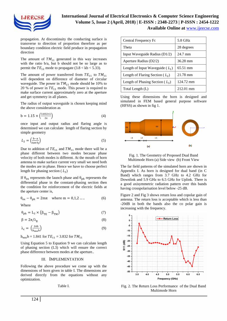
Figure 2 and Fig 3 shows return loss and copolar gain of
antenna. The return loss is acceptable which is less than
-20dB in both the bands also the co polar gain is
increasing with the frequency.
Fig. 2. The Return Loss Performance of the Dual Band
Multimode Horn

International Journal of Electrical Electronics & Computer Science Engineering
Volume 5, Issue 2 (April, 2018) | E-ISSN : 2348-2273 | P-ISSN : 2454-1222
Available Online at www.ijeecse.com
125
Fig. 3. Copolar Gain Variation in C Band for the
Proposed Dual Band Multimode Horn
Fig 4 shows the peak crosspolarisation in diagonal plane
(45 degree). the bandwidth for lower Frequency band is
about 39% and in higher frequency band it is 18.80 %.
Fig. 4. Peak Crosspolarisation in Diagonal Plane (45
Degree) for the Proposed Dual Band Multimode Horn
IV. CONCLUSION
A new dual-band multimode smooth-walled horn
designed for C band satellite communication using very
simple formulae without any optimization..it offers
complete pattern symmetry in all the planes having
moderate gain and lower crosspolarisation at uplink and
downlink frequency bands with acceptable return loss.
Also the percentage bandwidth achieved in lower
frequency band is 39% and at higher frequency band it is
about 19%..so a wide band performance is obtained by a
single feed .
V. REFERENCES
[1]. P. J. Clarricoats and A. D. Olver “Corrugated
Horns for Microw. Antennas”1984, Peter
Peregrinus
[2]. P. D. Potter "A new horn antenna with suppressed
sidelobes and equal beamwidths" Microw. J., pp.
71-78, 1963
[3]. E. Lier "Cross polarization from dual mode horn
antennas" IEEE Trans. Antennas Propag., vol. AP-
34, no. 1, pp. 106-110, 1986
[4]. R. Turrin "Dual mode small-aperture antennas"
IEEE Trans. Antennas Propag., vol. 15, no. 2, pp.
307-308, 1967
[5]. G. Ediss "Technical memorandum: Dual-mode
horns at millimetre and submillimetre
wavelengths" IEEE Proc. H Microw. Antennas
Propag., vol. 132, no. 3, pp. 215-218, 1985
[6]. H. M. Pickett , J. C. Hardy and J. Farhoomand
"Characterization of a dual-mode horn for
submillimeter wavelengths" IEEE Trans. Microw.
Theory Tech., vol. 32, no. 8, pp. 936-937, 1984
[7]. S. P. Skobelev , B.-J. Ku , A. V. Shishlov and D.-
S. Ahn "Optimum geometry and performance of a
dual-mode horn modification" IEEE Antennas
Propag. Mag., vol. 43, no. 1, pp. 90-93, 2001
[8]. T. S. Bird "A multibeam feed for the Parkes radio-
telescope" Proc. IEEE Antennas Propagation
Symp., pp. 966-969, 1994
[9]. S. M. Tun and P. R. Foster "Computer optimised
wideband and dual-mode horn" Electron. Lett.,
vol. 38, no. 15, pp. 768-769, 2002
[10]. G. Yassin , P. Kittara , A. Jiralucksanawong , S.
Wangsuya , J. Leech and M. Jones "A high
performance horn for large format focal plane
arrays" Proc. 18th Int. Symp. on Space Terahertz
Technology, pp. 199-210, 2007
[11]. P. Kittara , A. Jiralucksanawong , G. Yassin , S.
Wangsuya and J. Leech "The design of potter
horns for THz applications using a genetic
algorithm" Int. J. Infrared Millimeter Waves, vol.
28, pp. 1103-1114, 2007
[12]. C. Granet , G. L. James , R. Bolton and G. Moorey
"A smooth-walled spline-profile horn as an
alternative to the corrugated horn for wide band
millimeter-wave applications" IEEE Trans.
Antennas Propag., vol. 52, no. 3, pp. 848-854,
2004
[13]. J. M. Neilson "An improved multimode horn for
Gaussian mode generation at millimeter and
submillimeter wavelengths" IEEE Trans. Antennas
Propag., vol. 50, no. 8, pp. 1077-1081, 2002
[14]. Carpenter E. 1980, 'A Dual-Band Corrugated Feed
Horn,' Anten, and Prop. Society Int. Symp., Vol.
18, 213-216.

International Journal of Electrical Electronics & Computer Science Engineering
Volume 5, Issue 2 (April, 2018) | E-ISSN : 2348-2273 | P-ISSN : 2454-1222
Available Online at www.ijeecse.com
126
[15]. D. Olver , P. J. B. Clarricoats , A. A. Kishk and L.
Shafai "Microw. Horns and Feeds "1994, IEEE
Press
[16]. W. Love (ed.), Electromagnetic Horn Antennas
(New York: IEEE Press, 1976).
[17]. K. K. Agarwal and E. R. Nagelberg, “Phase Characteristics of a Circularly Symmetric Dual-
mode Transducer,” IEEE Trans. Microwave
Theory Tech., vol. MTT-18 (December 1970): 69–
71.
[18]. W. J. English, “The Circular Waveguide Step-
discontinuity Mode Transducer,” IEEE Trans.
Microwave Theory Tech., vol. MTT-21 (October
1973): 633–636
[19]. T. Satoh, “Dielectric Loaded Horn Antennas,” IEEE Trans. Antennas Propagat., vol. AP-20
(March 1972): 199–201.
[20]. K. Tomiyasu, “Conversion of TE11 Mode by a
Large Diameter Conical Junction,” IEEE Trans.
Microwave Theory Tech., vol. MTT-17 (May
1969): 277–279.
APPENDIX I
(A)
(B)
(C)
(D)
Fig. 5. Far Field Radiation Pattern Of Propose Multimode D Horn for Downlink Communication (A) Radiation Pattern at
3.7 GHz. (B) Radiation Pattern at 3.9 GHz (C) Radiation Pattern at 4.1 GHz (D) Radiation Pattern at 4.3 GHz.

International Journal of Electrical Electronics & Computer Science Engineering
Volume 5, Issue 2 (April, 2018) | E-ISSN : 2348-2273 | P-ISSN : 2454-1222
Available Online at www.ijeecse.com
127
(E)
(F)
(G)
(H)
Fig. 6. Far Field Radiation Pattern of Propose Multimode D Horn for Uplink Communication (E) Radiation Pattern at
5.7 GHz (F) Radiation Pattern at 5.9 GHz (G) Radiation Pattern at 6.1 GHz (H) Radiation Pattern at 6.3 GHz.