design and analysis of hat-stiffened conical shell for
TRANSCRIPT
Design and Analysis of Hat-Stiffened Conical Shell for Axial Compression
M. Barath1, Rajesh K R2
1M. Tech Student, Machine Design Dept., REVA University, Bangalore 2Asst. Professor, School of Mechanical Engineering, REVA University, Bangalore
Abstract— this study aims to design and analysis of Hat stiffened conical shell for under axial compression. Shells may be subjected to axial compres-
sion, bending, twisting or external or internal pressure anyone of which can cause failure. Depending on the geometry of the conical shell either local or
overall buckling failures can occur. To provide additional strength, axially compressed conical shells are sometimes Hat stiffeners are placed. Further, the
Hat stiffeners are placed on the inner periphery of the skin for the model. Moreover, hat stiffeners placed on the inner periphery provides more BLF than
the stiffeners placed in the outer periphery of the skin. Buckling load carrying capacity of the stiffened conical shell is compared with analysis software
Abaqus.in this study only aims buckling analysis. Theoretical calculations are also carried out for verify the results obtained from finite element analysis.
Aircraft aluminum alloy (AA2014 T6) is chosen for these project.
Index Terms— shells, buckling, stiffeners
—————————— ◆ ——————————
1 INTRODUCTION
A launch vehicle is a vehicle which carries a payload / satellite
from surface of the earth through the outer space, either to
another surface point or into space. A launch system usually
consists of the launch vehicle, the launch pad and other infra-
structure. A launch vehicle generally consists of several differ-
ent segments or stages, with each stage playing its own role.
The first stage of the rocket or the launch vehicle usually con-
tains fuel that is needed to lift the satellite and launch vehicle
from the ground and into the sky. A launch vehicle at lift-off
weighs hundreds of tons, so the rockets have to be very
strong. After all the fuel has been used up by the vehicle, the
first stage will get broken offs from the remaining structure
and then falls to the ground.The second stage of the launch
vehicle contains smaller rockets which ignite after the first
stage is finished. The rockets of second stage carry their own
fuel tanks. It is used to transport the satellite into space similar
to that of the first stage and finally it breaks off after all the
fuel has been used up and burns in the atmosphere.The final
stage of the launch vehicles is connected to the satellite itself,
which is enclosed a metal shield commonly known as fairings.
The fairings break apart once the satellite is above the atmos-
phere of the earth and burns up in the earth’s atmosphere. The
rocket of the upper stage gets fired after the satellite in exact
location where it is needed.in the fina lstage conical shell play-
ing important role in each and every launch vehicle. The fail-
ure of the conical shell which is compressed in one or another
way is represented by buckling.The phenomenon of the buck-
ling process generally occurs when the deformations are very
high.The criteria’s such as specific strength,stability and de-
flection requirements should be met by the structure to be de-
signed. The design procedures recommended for isotropic
conical shells under such loading conditions as axial compres-
sion, bending, hydrostatic pressure, and torsion, along with
those of combined loads.But this report aims only isotropic
conical shell for axial compression.To design the structure, hat
stiffeners are provided on the conical shell surface. Hat stiff-
ener is provided in order to increase the stiffness of the conical
shell. The Hat stiffeners are attached throughout the length of
conical shell. AA2014 T6 Aluminium alloy used for this de-
sign.
2 LITERATURE REVIEW J. Singer [2] discussed about the experimental and theoretical
study of the buckling of closely stiffened conical shell under
axial compression to determine the influence of the stiffener
geometry and spacing based on linear theory. The experi-
mental results were correlated with theory and appropriate
design criteria are developed. Seide, P [3] presented and
solved stability equations for thin circular orthotropic conical
shells for external pressure, axial compression and combined
loading. The general instability of closely stiffened conical
shells under hydrostatic pressure is also analysed by accurate
approach. Preliminary experimental results for buckling of
ring-m stiffened conical shells under hydrostatic pressure are
presented and discussed. Weingarten, V.I [4] results of an ex-
tensive experimental program on the stability of cylindrical
and conical shells under axial compression are presented and
discussed. The stability of cylindrical and conical shells under
axial compression is a problem that has been discussed both
theoretically and experimentally. And this paper discussed
about the buckling and post buckling behaviour of the thin-
International Journal of Scientific & Engineering Research Volume 11, Issue 6, June-2020 ISSN 2229-5518 615
IJSER © 2020 http://www.ijser.org
IJSER
walled cylindrical and conical shells under axial compression.
Hausrath A.H.; and Dittoe, F.A [5] many studies have been
conducted of the buckling of conical shell under various load-
ing conditions. While the behaviour of two types of shells ap-
pears to be similar, significant differences in experimental re-
sults remain unexplained. In addition, some important load-
ing cases and the effects of edge conditions remain to be ex-
plained. And this paper present recommended design proce-
dures for isotropic conical shells under axial compression,
bending, along with those of combined loads. H. L. Cox [7]
briefed the Buckling of Plates and Shells loading under the
hydrostatic pressure and lateral pressure varying in the axial
direction. The stability equations for thin conical shells de-
rived in this paper and stability equation in the radial direc-
tion is derived in a modified form similar to that given by ga-
lerkin method. Typical cases are analyzed. The results for hy-
drostatic pressure loading are compared with results found by
other investigators and with those obtained by Hoof and the
author in an analysis restricted to small cone angles. David
L.Block, Michael F.Card [8] derived from energy principles
based on small-deflection theory for buckling of stiffened or-
thotropic cylinders which includes eccentricity (one-sided)
effects of the stiffeners. The calculations of the conical shell
effects are large even with large diameter shells and should be
obtained from the buckling analysis. C. Huhne, R. Rolfes, J.
Tebmer [9] discussed the Thin- walled shell structures like
circular cylindrical shells are prone to buckling. The results of
test and numerical analysis indicate that this new determinis-
tic approach has the potential to provide an improved and less
conservative shell design in order to reduce mass and cost of
thin- walled shell structures made from the different types of
materials. L. W. Rehfield [10] the volume of literature con-
cerned with the buckling of circular cylindrical shells subject-
ed to axial compression and bending is overwhelming, con-
fused and filled with conflicting opinions, theories and state-
ments. The approach is indirect a beings by considering the
applied stress level as a primary design variable. A new meth-
od for he sizing and spacing of rings is outlined and illustrat-
ed. The design calculations as the classical theory are to be
correlated with the test results. C.J Balasubramaniam, S. Si-
rajudeen Ahmed [11] studied the effect of stiffener eccentrici-
ty on the buckling strength of closely stiffened cylindrical
shell. Using the theoretical calculation, a parametric study is
carried out to assess the influence of stringers and rings inside
and outside shell structures. Theoretical formulation results
were compared with finite element buckling analysis results. It
was found that outside stiffened structures, buckling capacity
varies from 150% to 220% of inside stiffened structure. Mat-
thew A. Dawson, Lorna [13] addressed the optimization of
cylindrical shells with compliant cores. Thin-walled shell with
a compliant core presented discussed the optimal design for a
given radius, prescribed materials, and specified axial load.
The analysis also reveals more effective than a foam core con-
figuration. Theoretically, the optimized cylinder with a honey-
comb, compliant core demonstrates substantial improvement
in load bearing capability over the comparable designs, in-
cluding the equivalent hollow cylinder, the optimization hat-
stiffened cylinder and the optimized sandwich designs. Bo
Wang, Shiyang Zhu, Peng Hao [14] discussed the buckling of
quasi- perfect cylindrical shell under axial compression. Finite
element numerical procedure for predicting the buckling load
was developed. Results shows buckling load predicted by the
FE analysis is very close to that from the test. And buckling
behaviour also discussed based on Fourier series method.
Kaifan Du, Kuo Tian, Yu Sun [15] in this paper analysis was
carried out on the hat-stringer-stiffened flat panels in order to
assess their buckling and post-buckling responses when ex-
posed to axial compression. The effect of test fixtures on buck-
ling, post-buckling and failure type of the plate were investi-
gated. Panel tested with test fixtures had a large pre-buckling
and post-buckling and post- buckling axial stiffness. Test fix-
tures playing the significant role in experiments and accurate
test results need good test fixtures. The results showed that
hat-stringer flat panel had large load capacity after initial
buckling.
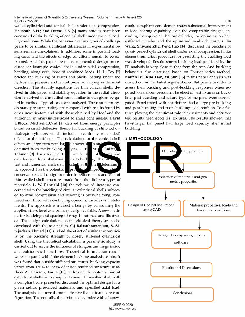
3 METHODOLOGY
Definition of the problem
Selection of materials and geo-
metric properties
Design of Conical shell model
using CAD
Design checkup using abaqus
software
Results and Discussions
Conclusions
Material properties, loads and
boundary conditions
International Journal of Scientific & Engineering Research Volume 11, Issue 6, June-2020 ISSN 2229-5518 616
IJSER © 2020 http://www.ijser.org
IJSER
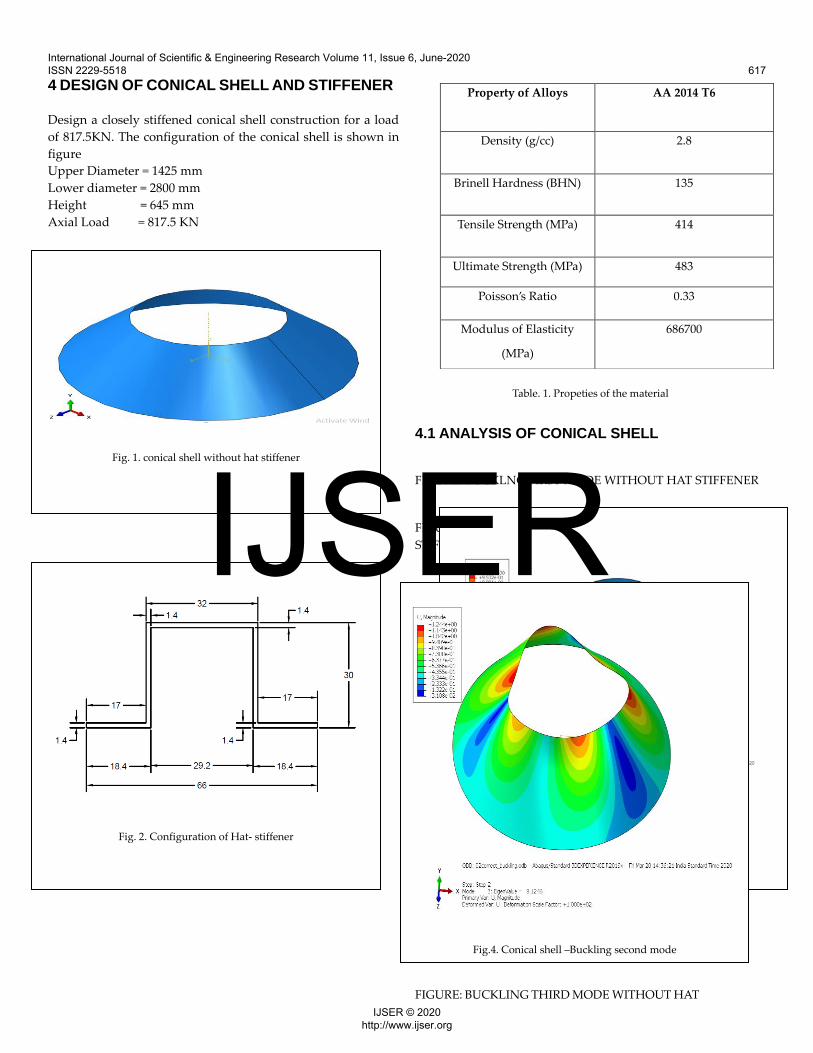
4 DESIGN OF CONICAL SHELL AND STIFFENER
Design a closely stiffened conical shell construction for a load
of 817.5KN. The configuration of the conical shell is shown in
figure
Upper Diameter = 1425 mm
Lower diameter = 2800 mm
Height = 645 mm
Axial Load = 817.5 KN
PROPERTIES OF THE MATERIAL
Table. 1. Propeties of the material
4.1 ANALYSIS OF CONICAL SHELL
FIGURE: BUCKLNG FIRST MODE WITHOUT HAT STIFFENER
FIGURE: BUCKLING SECOND MODE WITHOUT HAT
STIFFENER
FIGURE: BUCKLING THIRD MODE WITHOUT HAT
Property of Alloys AA 2014 T6
Density (g/cc) 2.8
Brinell Hardness (BHN) 135
Tensile Strength (MPa) 414
Ultimate Strength (MPa) 483
Poisson’s Ratio 0.33
Modulus of Elasticity
(MPa)
686700
Fig. 1. conical shell without hat stiffener
Fig. 2. Configuration of Hat- stiffener
Fig. 1. conical shell without hat stiffener
Fig.3. Conical shell –Buckling first mode
Fig.4. Conical shell –Buckling second mode
International Journal of Scientific & Engineering Research Volume 11, Issue 6, June-2020 ISSN 2229-5518 617
IJSER © 2020 http://www.ijser.org
IJSER
STIFFENER
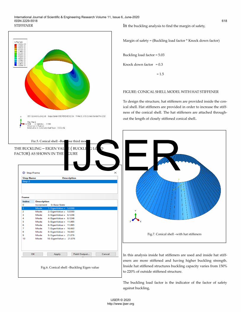
THE BUCKLING – EIGEN VALUE ( BUCKLING LOAD
FACTOR) AS SHOWN IN THE FIGURE
In the buckling analysis to find the margin of safety,
Margin of safety = (Buckling load factor * Knock down factor)
Buckling load factor = 5.03
Knock down factor = 0.3
= 1.5
FIGURE: CONICAL SHELL MODEL WITH HAT STIFFENER
To design the structure, hat stiffeners are provided inside the con-
ical shell. Hat stiffeners are provided in order to increase the stiff-
ness of the conical shell. The hat stiffeners are attached through-
out the length of closely stiffened conical shell.
In this analysis inside hat stiffeners are used and inside hat stiff-
eners are more stiffened and having higher buckling strength.
Inside hat stiffened structures buckling capacity varies from 150%
to 220% of outside stiffened structure.
The buckling load factor is the indicator of the factor of safety
against buckling,
Fig.5. Conical shell –Buckling third mode
Fig.6. Conical shell –Buckling Eigen value
Fig.7. Conical shell –with hat stiffeners
International Journal of Scientific & Engineering Research Volume 11, Issue 6, June-2020 ISSN 2229-5518 618
IJSER © 2020 http://www.ijser.org
IJSER
BLF = Buckling load / applied load
The buckling load factor if equal to one then the applied load is
exactly equal to the critical load buckling is expected. The buck-
ling load factor is less than one then the applied load exceeds the
estimated critical loads buckling will occur.
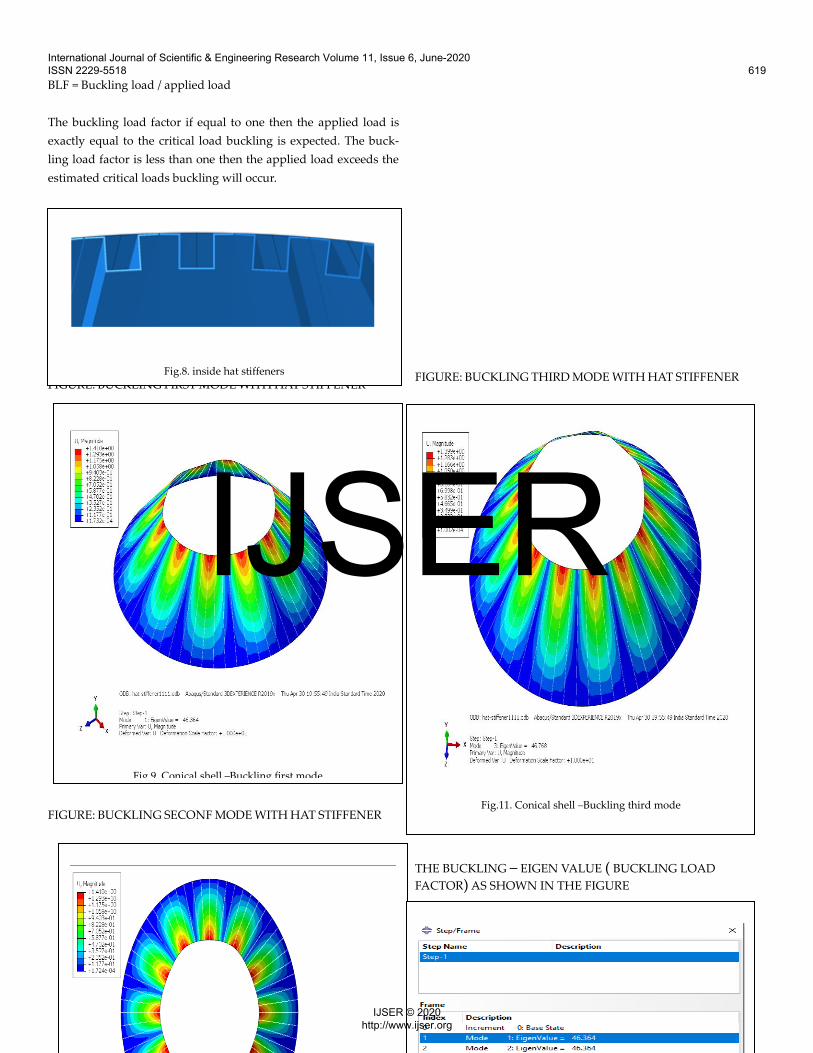
FIGURE: BUCKLING FIRST MODE WITH HAT STIFFENER
FIGURE: BUCKLING SECONF MODE WITH HAT STIFFENER
FIGURE: BUCKLING THIRD MODE WITH HAT STIFFENER
THE BUCKLING – EIGEN VALUE ( BUCKLING LOAD
FACTOR) AS SHOWN IN THE FIGURE
Fig.8. inside hat stiffeners
Fig.9. Conical shell –Buckling first mode
Fig.11. Conical shell –Buckling third mode
International Journal of Scientific & Engineering Research Volume 11, Issue 6, June-2020 ISSN 2229-5518 619
IJSER © 2020 http://www.ijser.org
IJSER

In the buckling analysis to find the margin of safety,
Margin of safety = (Buckling load factor * Knock down factor)
Buckling load factor = 46.3
Knock down factor = 0.3
= 13.89
5 RESULTS AND DISCUSSIONS
6 CONCLUSIONS
1. Study of buckling load factor for hat stiffened conical shell
for axial compression.
2. Static and Buckling analysis has been carried out to estimate
the von misses stress, deformation and buckling load factor.
3. BLF is determined through FE analysis for hat stiffened con-
ical shell and hat stiffeners mounted at the inside the conical
shell.
4. The difference between with and without hat stiffeners
buckling load factor has been carried out.
5. Finally with hat stiffeners conical shell is high stiffer than
without hat stiffener.
7 ACKNOWLEDGMENT I would like to thank VSSC for giving me opportunity to un-dergo research work and also I would like to thank Mr. VAMSI, VSSC for providing encouragement and valuable suggestions to carry out my research work.
8 REFERENCES 1. Kabe, A. M., & Kendall, R. L. (2010). Launch Vehicle
Operational Environments. Encyclopedia of Aero-
space Engineering.
2. J. Singer, “The influence of stiffener geometry and
spacing on the buckling of axially compressed cylin-
drical and conical shells” Prelim. Preprint paper, 2nd
IUTAM Symp. Theory of Thin shells, Copenhagen,
1967
3. Seide, P.: Axisymmetric Buckling of Circular Cones
Axial Compression. J.Appl. Mech., vol.23, no. 4, Dec.
1956, pp. 625-628.
4. Weingarten, V.I.; Morgan, E. J.; and seide, P.: Elastic
stability of Thin-walled cylindrical and conical shells
under axial compression. AIAA J., vol,3 no.3, Mar.
1965, pp. 500-505.
5. Hausrath, A.H.; and Dittoe, F.A.: Development of de-
sign strength levels for the Elastic stability of Mono-
coque cone under axial compression. Collected papers
on instability of shell structures, NASA TN D-1510,
1962, pp. 45-56.
International Journal of Scientific & Engineering Research Volume 11, Issue 6, June-2020 ISSN 2229-5518 620
IJSER © 2020 http://www.ijser.org
IJSER

6. Gerard, G.; and Becker, H.: Handbook of structural
stability. Part III, buckling of curved plates and shells.
Supplement to NACA TN 3783, 1957.
7. Buckling of Plates and Shells, (1963), H. L. Cox, Per-
gamon Press, Paris.
8. David L.Block, Michael F.Card, “Buckling of eccentri-
cally stiffened orthotropic cylinders.” Nasa Technical
note NASA TN D-2960, 1965.
9. C. Huhne, R. Rolfes, J. Tebmer, “design of composite
cylindrical shells under axial compression”– simula-
tion and validation 46-2008.
10. L. W. Rehfield , “Design of Stiffened Cylinders to Re-
sist Axial Compression” NASA TN D-5561, 1969.
11. C.J Balasubramaiam, S. Sirajudeen Ahmed, “Effect of
stringer eccentricity on the strength of closely stiff-
ened shell structure” – A study”
VSSC/SDE/SP/005/2005.
12. Vasanthanathan. A, Venkateshwaran , “On the re-
sponse of Foam filled hat- stiffened CRPF shells un-
der axial compression” vol. 4 , no.9,pp. 1-10.
13. Matthew A. Dawson, Lorna, Optimization of cylin-
drical shells with compliant cores, Cambridge”, MA
02139 – 2005.
14. Bo Wang, Shiyang Zhu, Peng Hao, “Buckling and op-
timization of the hat-stringer- stiffened composite
panels under axial compression”, Beijing 100084.
15. Kaifan Du, Kuo Tian, Yu Sun, “Imperfection- insensi-
tive design of stiffened conical shell based on equiva-
lent multiple perturbation load approach", Dalian
116023.
16. Yuming Mo, Dongyun Ge, Boling He, “Experiment
and optimization of the hat-stiffened composite pan-
els under axial compression”, Beijing 100084.
17. John W.Hutchinson, John C.Amazigo, “Imperfection-
Sensitivity of eccentrically stiffened cylindrical shells”
AIAA Journal vol. 5, No. 3, 1967.
International Journal of Scientific & Engineering Research Volume 11, Issue 6, June-2020 ISSN 2229-5518 621
IJSER © 2020 http://www.ijser.org
IJSER