design and analysis of flat joint connection of double ... · pdf fileit is known as front...
TRANSCRIPT

IOSR Journal of Mechanical and Civil Engineering (IOSR-JMCE)
e-ISSN: 2278-1684,p-ISSN: 2320-334X, Volume 13, Issue 4 Ver. II (Jul. - Aug. 2016), PP 114-121
www.iosrjournals.org
DOI: 10.9790/1684-130402114121 www.iosrjournals.org 114 | Page
Design and analysis of flat joint connection of double wishbone
suspension A arm
Mr. Mahesh H. More1, Dr. Shekhar Yadgiri Gajjal
2
1(Mechanical design, N.B.N.Sinhgad school of Engineering affiliated to Savitribai Phule Pune University, India)
2(H.O.D. (M.E.) Mechanical design, N.B.N.Sinhgad school of Engineering affiliated to Savitribai Phule Pune
University, India)
Abstract: Work involves new product development into A arm component for automotive development. Frame
round cage roll is having sustaining issue so to resolve the issue here A arm mounting get changed and
instead of round bar weldment flat frame design incorporated. So to make stability in off highway vehicle as
strength point of view this sustaining project executed. It’s a redesigning work with A arm while installation
may having difficulties so to make feasible and safe installation, A arm structure is changed with its joint of
assembly instead of pipe joint. We developed here U joint with bolting on flat frame. CAE comparison is taken
to make validation, boundary conditions considered here are standard input and referred by standard similar
configurations.
Keywords: A-arm, CAE, Flat Frame, U-joint, Validation.
I. Introduction 1.1 Problem Identification and Overcomes
Frame round cage roll is having sustaining issue so to resolve the issue here A arm mounting get
changed and instead of round bar weldment flat frame design incorporated. Presently cage is in tube weldment
structure as the roll cage is having limitation on crushing loads sustaining behaviour, now we need to change
frame handling stability of roll cage with holding all load on it and assembling roll cage on flat flame cut frame.
So now mounting of all the subordinates and subassemblies will get change and modification and new
designing is existing for A arm suspension assembly. So to replace joints between roll cage frame and A arm
this modifying and sustaining work is executed and this is a need of strengthening the product in standardized
process.
Fig. 1
1.2 Literature Survey
Asst. Prof. N.Vivekanandan[1]
conducted study on Double Wishbone suspension system. Double
Wishbone Suspension System consists of double lateral controlling arms (upper arm and lower arm) usually of
dissimilar length along with a over spring and shock absorber assembly. It is known as front suspension mostly
installed in rear wheel power drive vehicles. Design of double wishbone suspension system taking with
formulation of spring plays a very effective role in creating the stability of the vehicle body. This type of
system increasing negative camber obtaining all the straight way to full jounce travel unlike Macpherson Strut.
They also allow simple adjustment of wheel assembly like camber. Double wishbone suspension assembly has
super dynamic characteristics as well as load-handling power. Design of wishbones is the starting stage to
design and formulate the suspension system. The material is obtaining using Pugh’s Concept of Optimization.
Basically on the properties of the selected body material, the allowable stress is calculated using standard sheer
stress theory of failure occurs. The body roll-centre is determined to find the tie-rod simple length. The designed

Design and analysis of flat joint connection of double wishbone suspension A arm
DOI: 10.9790/1684-130402114121 www.iosrjournals.org 115 | Page
Wishbones are modelled using soft tool and then validate using Ansys software to find the maximum
stress and maximum deformation in the body wishbone.
Material Selection of Wishbone [1]
. This becomes the most primary need for design and producing. The
capability of the material should be well controlled to withstand all the loads acting on it in all conditions. The
material selection also depends on number of parameters such as carbon content, material properties, availability
and the most important parameter is the costing. In starting 3 materials are selected based on their availability in
the nearer market AISI 1018, AISI 1040 and AISI 4130. By using Pugh’s concept of engineering optimization,
we have chosen material grade AISI 1040 for the wishbones body.
Eshaan Ayyar,Isacc de Souza, Aditya Parvin, Sanket Tambe, Aqleem Siddiqui and Nitin Gurav
conducted study on suspension system for ATV[2]
. REAR WISHBONE. Rear wishbone in starting, the A-arm
was installed for the back suspension. While the vehicle body takes a turn, due to the horizontal loads acting on
the links attached of the wishbones and the knuckle joint and due to avoiding less steering on the rear wheels,
there can be toe-in and toe-out of the wheels. This may lead to unbalanced steering and may result in unbalance
body. Excess toe-in can impact over steer while moment leading to loss of control. Excess toe-out can cause
with steering while turning. To avoid any toeing, the A-arm shape is converted into H- shaped arm (as shown in
below). Thus the vertical pin knuckle-wishbone assembly structure is replaced into horizontal pin attachment.
This avoids formation of an axis and due to which the chances of toeing of the wheels with body. This gives full
proofed balancing, align and steering. It also expands the ride stability.
Fig. 2 Rear Wishbone
[2]
1.3 Objective
1.3.1 To Design customized A arm for flat joint of roll cage.
1.3.2 To verify sustainability with joint.
1.3.3 To standardize wishbone A arm particularly on flat joint assembly.
1.4 Testing Using Software Ansys Workbench
Testing the assembly structure using software tools initially some basic load distribution calculations
are done to get the values of force acting on each of the member arms. Here the upper and lower wishbones are
tested on ANSYS for determining rigidity and safety of the arms. A force of 3G Newton was applied to the base
of tyre considering weight transfer during braking and jounce/rebound. This force was transmitted to the upper
and lower links and is calculated by simple vector mechanics. The software is used to calculate the maximum
deformation and the maximum equivalent stress induced in the arms. The behaviour of the arms is discussed
below [3]
Fig.3 A arm total deformation
[3] Fig 4. A arm equivalent stress
[3]

Design and analysis of flat joint connection of double wishbone suspension A arm
DOI: 10.9790/1684-130402114121 www.iosrjournals.org 116 | Page
II. Design Consideration
Boundary conditions:
Considering rough conceptual stage
Stress Calculation For ductile materials, allowable stress is obtained by the following relationship
𝜎 =𝑠𝑦𝑡
𝑓𝑠
Assume factor of safety, fs = 1.2
(as is a ductile material).
𝜎 = 415/1.2 = 345.83MPa
It is the Amount of allowable stress in the wishbones structure. The designed wishbone is safe when the Opting
stress is under the allowable stress. The allowable stress is obtained using Ansys analysis CAE tool.
Fig.5 Under static loading condition
Consider the vehicle shown in Figure.
The total weight of off highway motor acting at its centre of gravity is:
G = m X g........................................... (1)
The loads coming on front side and rear side axles are out by using the equilibrium Equations;
𝐺𝐹𝐴= 𝐺 𝐿𝑅
𝐿 ………………………... (2)
𝐺𝑅𝐴= 𝐺 𝐿𝐹
𝐿 ………………………... (3)
Static conditional load on single wheel of the front axle is:
𝐺𝐹𝐴𝑤 = 𝐺𝐹𝐴
2 ………………………….. (4)
𝐺𝑅𝐴𝑤 = 𝐺𝑅𝐴
2 ………………………….. (5)
By using above formulation for the object (vehicle) of total standard mass 2300 kg and at constant
speed we assumed 30 km/hr., we can determine condition on one wheel of the object so far it will be the
weight on lower suspension arm of front side wheel.
If m=2300kg,
From Equation no. (1)
G = 2300 x 9.81 N
G = 22563 N
The loads on front axle can be calculate using equation no. (2)
𝐺𝐹𝐴 = 22563x (1285/2900)
𝐺𝐹𝐴 = 9997.7431 N
Load on the rear axle is by using equation (3)
𝐺𝑅𝐴 = 22563x (1615/2900)
𝐺𝑅𝐴 = 12565.2569 N
Load on the front wheel and rear wheel can be found by using equation no. (4) and (5)
𝐺𝐹𝐴𝑤 = 9997.7431/2 𝐺𝐹𝐴𝑤 = 4998.8715 N
Similarly,
𝐺𝑅𝐴𝑤 = 6282.6284 N
From result of boundary loads for standard required vehicle we got load on the front side wheel 4997.8715 N
and for rear wheel it is 6282.6284 N.

Design and analysis of flat joint connection of double wishbone suspension A arm
DOI: 10.9790/1684-130402114121 www.iosrjournals.org 117 | Page
We are focusing on A arm design so wheel consideration is only our zone for analysis we consider forces on
lower suspension arm 4997 N which can be considered equal to 5000 N. So, for our further formulation we
consider load of 5000 N acting on front lower A arm.
So we can now develop the 3 model of Arm suspension and applying load.
Fig. 6 Holding Bracket Fig.7 New modified roll cage flat base frame
Frame for roll cage weldment on which A arm mounting is to be made feasible. This plate is 16 mm
thicken and made from flame cutting from raw material of big size sheet. This part is in one piece formation
applying flame cutting and smooth corners at every edge.
Fig. 8 Subassembly of U clamp
Fig. 9. Flat flange Fig. 10. A shaped weldment formation
Now A shaped clamp is taking all loads on it so let’s define the configure values to it.
Performance under working conditions of L shape lower part of U clamp as we knows that all the loads will
exerted on lower L shape vertically but still we designed U clamp because of fastening and holding purpose of
wishbone A arm.

Design and analysis of flat joint connection of double wishbone suspension A arm
DOI: 10.9790/1684-130402114121 www.iosrjournals.org 118 | Page
Loads we are considering per unit area
Fig. 11
As seen from the Bending moment Diagram,
Maximum bending moment M = 73500 N-mm Moment of inertia, I = bt
3 / 12
I = (30 x 103) / 12
I = 2500 mm4
The bending stress in the member is calculated as 𝑀
𝐼=
𝜎
𝑦
73500
2500=
𝜎
4
Bending Stress, σ = 147.00 N/mm2
Deflection is Given by
𝛿 = 𝑤𝑙4
8𝐸𝐼
𝛿 = 30 𝑥 704
8 𝑥 200 𝑥 103 𝑥 2500
𝛿 = 0.18007 𝑚𝑚 Hence,
Maximum bending stress developed in the member = 147.00 N/mm2
And Maximum deflection of the member = 0.18007 mm
Fig. 12. Bending Moment diagram
Design and analysis of flat joint connection of double wishbone suspension A arm
DOI: 10.9790/1684-130402114121 www.iosrjournals.org 119 | Page
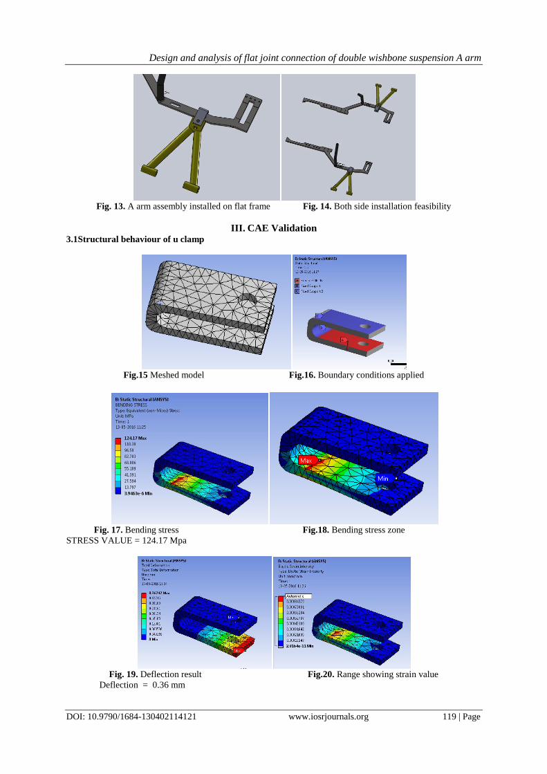
Fig. 13. A arm assembly installed on flat frame Fig. 14. Both side installation feasibility
III. CAE Validation 3.1Structural behaviour of u clamp
Fig.15 Meshed model Fig.16. Boundary conditions applied
Fig. 17. Bending stress Fig.18. Bending stress zone
STRESS VALUE = 124.17 Mpa
Fig. 19. Deflection result Fig.20. Range showing strain value
Deflection = 0.36 mm

Design and analysis of flat joint connection of double wishbone suspension A arm
DOI: 10.9790/1684-130402114121 www.iosrjournals.org 120 | Page
3.2Overall assembly behaviour
Fig. 21. Geometry Imported Fig. 22. Meshed Assembly
Fig. 23. Deformation Test Fig.24. Maximum Stress
From above, Deformation 6.3 mm and Maximum Stress is 69.73 Mpa
It’s found below yield strength of the material
Fig. 25. Stress Intensity Range
IV. Result From output data
Parameters Design CAE output
Max stress 147 Mpa 124.3 Mpa
Deflection 0.18 mm 0.36 mm
In assembly 79.885 Mpa stress reaches at maximum point, it can be considered as safe side working condition.
V. Conclusion The behavior under load performing strategy of the new designed joint with A-arm modification will
effectively work in maximum loaded boundary conditions from the results came out. It has been seen that this

Design and analysis of flat joint connection of double wishbone suspension A arm
DOI: 10.9790/1684-130402114121 www.iosrjournals.org 121 | Page
kind of A arm can be standardized for roll cage flat joint. So in All Terrain Vehicle (ATV) this can be used if
flat joint is present. Still somewhere improvement can be done where the assembly process will be highlighted
with new techniques of assembling A arm as compared to conventional A arm. Extra machining cost is taking
effect but no option, we have changed this design due to base frame changing occurs.
References [1] Asst.Prof.N.Vivekanandan, Abhilash Gunaki,Chinmaya Acharya, Savio Gilbert and Rushikesh Bodke, “ Design, Analysis and
Simulation of Double Wishbone Suspension System”, IPASJ International Journal of Mechanical Engineering (IIJME), Vol 2,Issue 6,June 2014
[2] Eshaan Ayyar,Isacc de Souza, Aditya Parvin, Sanket Tambe, Aqleem Siddiqui and Nitin Gurav,” Selection, Modification and
Analysis of Suspension System for an All Terrain Vehicle”, Int.J.on Theoretical and Applied Research in Mechanical Engineering,Vol-2, Issue -4 2013.
[3] Sarvadnya A. Thakare, Prasad C. Antapurkar,D.S.Shah, P.R.Dhamangaonkar and S.N.Sapali, ”Design and analysis of Modified
Front Double Wishbone Suspension for a Three Wheel Hybrid Vehicle.”, World Congress on Engineering Vol II, July 2015. [4] C.M.Choudhari..(2011,Jan) “Finite Element Analysis and testing of suspension arm.”, National conference on advance in
Mechanical engineering 2011.
[5] Vinayak Kulkarni and Anil Jadhav (2014,May) “Finite Element Analysis and Topology Optimization of Lower Arm of Double Wishbone Suspension using RADIOSS and Optistruct”, Int. J. of science and Research. Vol 3 Issue 5.
[6] A.M.Patil, A.S.Todkar, R.S.Mithari and V.V.Patil “Experimental and Finite Element Analysis of Left Side Lower Wishbone Arm
of Independent Suspension System”,IOSR Journal of Mechanical and Civil Engineering. Vol 7,Issue 2, pp 43-48, May-June 2013.
[7] Aniket Thosar,”Design, analysis and Fabrication of Rear Suspension System for an all Terrain Vehicle.”, Int.J.of scientific and
engineering research,Vol.5, Issue 11,Nov-2014.
[8] Ammar Qamar Ul Hasan “Simulation of ATV Roll Cage Testing”(Department of Mechanical Engineering, DIT University, India) IOSR Journal of Mechanical and Civil Engineering (IOSR-JMCE) e-ISSN: 2278-1684,p-ISSN: 2320-334X, Volume 12, Issue 3
Ver. II (May. - Jun. 2015), PP 45-49.