design & analysis of miniaturized asymmetric coplanar ... · design & analysis of...
TRANSCRIPT
Progress In Electromagnetics Research C, Vol. 57, 159–171, 2015
Design & Analysis of Miniaturized Asymmetric Coplanar Strip FedAntenna for Multi-Band WLAN/WiMAX Applications
Praveen V. Naidu* and Akshay Malhotra
Abstract—A novel, compact asymmetric coplanar strip (ACS)-fed multi-band antenna forBluetooth/WLAN/WiMAX applications is proposed and discussed in this paper. The proposed antennais composed of a simple monopole structure with a mirror-L shaped branch and two rectangular radiatingstrips. It has a very small size of 13.75 × 26 mm2 including the ground plane. The mirror-L shapedbranch excites a resonant mode at 2.5 GHz, and on the other side, ACS-fed monopole structure with tworectangular strips (one horizontal and one vertical) excite the resonant modes at 3.3 GHz and 5.75 GHzrespectively. By properly selecting the lengths and positions of these radiating branches, multibandoperation with wider impedance bandwidth can be achieved. The measured and simulated results showthat the antenna has impedance bandwidth of 200 MHz (2.40–2.60 GHz), and 2800 MHz (3.2–6.0 GHz),and it can cover the 2.4 GHz Bluetooth, 2.4/5.2/5.8 GHz WLAN and 3.5/5.5 GHz WiMAX bands. Theresonances achieved with this technique can be tuned independently, and the equations governing theresonances are given and confirmed by parametric studies. The proposed technique is further validatedby designing another antenna working at 1.8/1.9 GHz PCS, 3.5/5.5 GHz WiMAX, 5.2/5.8 GHz WLANbands.
1. INTRODUCTION
Nowadays, the demand for using Wireless Local Area Network (WLAN: 2.4–2.48, 5.15–5.35, and5.72–5.85 GHz) and Worldwide Interoperability for Microwave Access (WiMAX: 3.40–3.69, and 5.25–5.85 GHz) protocols has increased drastically because of its highend features such as cost effectiveness,wire free connectivity and short distance high speed data transfer technology. This has intensifiedthe need for multi-band antennas that work at these frequencies. Along with the multi-band feature,compactness is also required because of the limited space availability for an antenna element in allmodern communication devices (like mobile phones, portable laptops and handheld electronic gadgets).So designing an antenna that supports 2.4/3.5/5.2/5.5/5.8 GHz communication standards with compactsize has attracted significant attention. Various types of printed multi-band antennas have beenreported, such as monopole antenna with L- and E-shaped radiators [1], triangle-shaped antenna withΠ-shaped slot and T-shaped strip [2], rhombus slot antenna [3], L-shaped radiator with M-shapedstub in the ground plane [4], Bow-Tie shaped slot antenna [5], slotted rectangular patch antenna [6],rectangular patch with meandered slit [7], asymmetric coplanar strip (ACS)-fed F-shaped antenna [8],CPW-fed slot antenna [9], ring monopole antenna with double meandered lines [10], ACS-fed slotantenna [11]. Some of the reported antennas [1–11] perform well in the radiation characteristics, butthey operate in only WLAN band. Also, most of them have large size making it difficult to integratein the miniaturized communication devices. So there is a demand for designing compact multi-bandantennas having wideband characteristics.
To cover the WLAN and WiMAX application standards simultaneously, several other antennas havebeen reported [12–26]. For example, a tri-band antenna with rectangular ring, S- and U-shaped strips for
Received 23 April 2015, Accepted 29 May 2015, Scheduled 4 June 2015* Corresponding author: Praveen Vummadisetty Naidu ([email protected]).The authors are with the Centre for Radio Science Studies, Symbiosis International University, Lavale, Pune 412115, India.

160 Naidu and Malhotra
WLAN and WiMAX applications is presented [12], and a novel rupee-shaped CPW-fed antenna in [13],and an octagonal shaped slot antenna in [14] are reported for dual/tri-band applications. A rectangularring patch monopole antenna with two inverted L-shaped strips [15], rectangular patch antenna withU-shaped slots [16], in [17], triple-band operation is achieved with L-shaped slot cut in the radiatingpatch and an inverted L-shaped stub in the ground plane. Rhombus slot antenna is reported in [18],circular patch with L-shaped slots in [19], hybrid strips monopole antenna in [21], a microstrip antennawith open-ended slot on the ground plane in [22], triangular shaped monopole dual-band antenna in [23],and a novel compact omega shaped ACS-fed antenna in [24]. To reduce the size, some other compactantennas designed using the concept of ACS-fed are given in [26–32]. Although some of the reportedantennas [27–30] are compact in size, most of them operate at limited frequencies in WLAN/WiMAXbands. For example an antenna reported in [27] covers only 3.5/5.8 GHz application bands; antennasin [28, 29] covers only 2.4/5.8 GHz WLAN band; an antenna reported in [30] covers only 2.4/5.8 GHzWLAN and 3.5 GHz. WiMAX bands. In Table 1, a comparison of tri-band antennas in terms of antennasize, application, total area occupied by the antenna, its frequency of operation and average peak gainshas been given. From the table it can be seen that the proposed antenna is the smallest coveringmaximum number of bands and applications and has a comparable if not higher gain. Majority of thereported antennas have drawbacks of large size and/or limited frequency of operation compared withour proposed design. The proposed antenna also has a simple structure with independent tunability ofresonant frequency which other designs rarely offer.
Table 1. Comparison of proposed antenna performance with other multi-band antennas.
Published
literature
Antenna
size (mm2)
Total area
occupied (mm2)
Antenna Purpose Avg Peak
gain (dBi)WLAN WiMAX
[12] 35 × 25 875 2.4/5.2/5.8 GHz 3.5/5.5 GHz 2.4
[16] 25 × 18 450 2.4/5.2/5.8 GHz 3.5/5.5 GHz 3.7
[17] 17 × 30 510 2.4/5.2/5.8 GHz 3.5/5.5 GHz 2.0
[19] 22 × 41 902 2.4/5.2/5.8 GHz 3.5 GHz 3.5
[20] 40 × 40 1600 2.4/5.2/5.8 GHz 3.5/5.5 GHz 3.3
[21] 38 × 20 760 2.4/5.8 GHz 3.5 GHz 3.1
[22] 14 × 34 476 2.4/5.8 GHz 3.5 GHz 1.7
[25] 18 × 28 504 2.4/5.2/5.8 GHz 3.5/5.5 GHz 2.7
[26] 35 × 19 665 2.4/5.2/5.8 GHz 3.5/5.5 GHz 3.6
[30] 26.5 × 12 318 2.4/5.8 GHz 3.5 GHz 2.0
Proposed
antenna13.75 × 26 357.5 2.4/5.2/5.8 GHz 3.5/5.5 GHz 3.25
In this paper, a compact multiband antenna fed by anasymmetrical coplanar strip (ACS) forWLAN/WiMAX applications is proposed. The antenna consists of an mirror-L shaped branch and tworectangle-shaped stubs connected with monopole structure. The measured operating bandwidths of theproposed antenna are about 200 MHz and 2800 MHz, respectively, which satisfies the 2.4/5.2/5.8 GHzwireless local area network (WLAN) and 3.5/5.5 GHz worldwide interoperability for microwave access(WiMAX), and 2.4 GHz Bluetooth/RFID/WiBree/ZigBee bands. The details of antenna evolutionprocess, parametric studies, experimental radiation patterns and peak gains are given in the followingsections.
2. ANTENNA EVOLUTION & DESIGN
Figure 1 shows the configuration and photograph of the proposed ACS-fed monopole multi-band antennadesigned for 2.4/5.2/5.8 GHz WLAN and 3.5/5.5 GHz WiMAX applications. The antenna is printed ona 13.75× 26 mm2 low-cost FR4 substrate having thickness of 1.6 mm, dielectric constant of 4.4 and losstangent tan δ = 0.02. Like CPW-feeding technique, a 50 ohm asymmetric coplanar strip transmission

Progress In Electromagnetics Research C, Vol. 57, 2015 161
line of width L1 = 3.3 mm, with a gap distance of g2 = 0.45 mm between the signal strip and groundplane, is considered for feeding the antenna. The electromagnetic simulation software CST microwavestudio package is used for design and analysis of the proposed antenna. The optimized dimensions ofthe proposed antenna are given as follows: W = 26, L = 13.75, W1 = 4.5, W2 = 3, L2 = 10, W3 = 3.5,L3 = 2.7, W4 = 13.6, L4 = 8.2, W5 = 2, L5 = 3, L6 = 3.4, g = 1.4 and g1 = 1.7 (all values are in mm).
The process of designing the proposed multi-band antenna is shown in Figure 2, and itscorresponding frequency versus reflection coefficient curves are given in Figure 3. Antenna #1 andAntenna #2 are the original ACS-fed monopole structures, which consist of a pair of mirror-L shapedbranches with width of 0.8 mm and a vertical rectangular stub with width of 1.7 mm, respectively. FromFigure 3, it can be seen that there are two independent resonant modes, one at 2.5 GHz WLAN banddue to mirror-L shaped branches and the other at 3.4 GHz WiMAX band due to rectangular stub.The next step is to integrate Antenna #1 and Antenna #2 structures (Antenna #3) to excite twosimultaneous resonant modes. As illustrated in Figure 3, (blue color), Antenna #3 covers the operatingband from 2.4–2.65 GHz and from 3.2–3.9 GHz. Meanwhile, the weak harmonics are located at 4.75 GHzand 6.0 GHz. Next step is to modify Antenna #3, so as to make it suitable for 5.2/5.8 GHz WLAN and5.5 GHz WiMAX applications. This is achieved by adding a quarter wavelength rectangular (horizontal)radiating element to Antenna #3. The resulting antenna structure is shown as proposed antenna inFigure 2. By adding rectangular stub to the monopole (red color), the third resonant mode at 5.75 GHzcan be achieved. The newly added structure hardly affects resonant frequencies that were achieved
Figure 1. Geometry and fabricated photograph of the proposed ACS-fed antenna.
Figure 2. Geometry of various antennas involved in the design evolution process.

162 Naidu and Malhotra
Figure 3. Simulated return loss curves of antennas involved in the design evolution process.
before. Also due to the strong harmonics, the second and third resonant bands are merged and form, awide band with improved return loss characteristics. Therefore, the proposed antenna with operatingbands from 2.4–2.6 GHz and 3.1–6.0 GHz for WLAN/WiMAX applications is obtained.
3. RESULTS AND DISCUSSION
The proposed multi-band antenna with optimized dimensions is fabricated, and its return losscharacteristics are validated experimentally by using R&S ZVA 40 vector network analyzer. It canbe seen from Figure 4(a) that the simulated and measured results show good agreement. The measured−10 dB impedance bandwidths are about 200 MHz (2.40–2.60 GHz) resonated at 2.5 GHz, and 2800 MHz(3.2–6.0 GHz) resonated at 3.7 GHz and 5.75 GHz, respectively, which can be used for 2.4 GHz Bluetooth,2.4/5.2/5.8 GHz WLAN and 3.5/5.5 GHz WiMAX bands. The slight difference between simulated andmeasured results is probably due to manufacturing tolerances, uncertainty of the thickness and/or thedielectric constant of the FR4 substrate and quality of SMA connector used.
In case of compact antennas, the currents may flow in external co-axial ground of connector andcable, which may disturb the return loss. So the proposed antenna is also simulated by considering theeffect of coaxial cable with SMA connector having dimensions that correspond to the actual connectorand cable used for measurements. In the CST software, the SMA connector is modeled using threecoaxial cylinders of length 10 mm (as shown in Figure 8 and Figures 4(b), (c), (d)) with an appropriateradius. The inner conductor of the cable has a radius of 0.65 mm; the outer conductor has an innerradius of 2.25 mm and an outer radius of 2.5 mm; the dielectric Teflon with a permittivity of 2.1 is usedto fill the space between inner and outer conductors. The co-axial cable connecting SMA connectorto VNA is also modeled to study its effect on return loss (given in Figure 4(a)) and surface currentdistribution (given in Figures 4(b), (c), (d)) on outer conductor of the cable. From Figure 4(a) it canbe observed that almost a similar return loss result can be observed with and without considering cablethat was connected to SMA connector in the simulation. Also in Figures 4(b), (c), (d), a very smallamount of current flows on the outer surface of the cable, which leads to negligible unbalanced currentsin coaxial cable. This explains the reason for good agreement between the simulated and measuredresults.
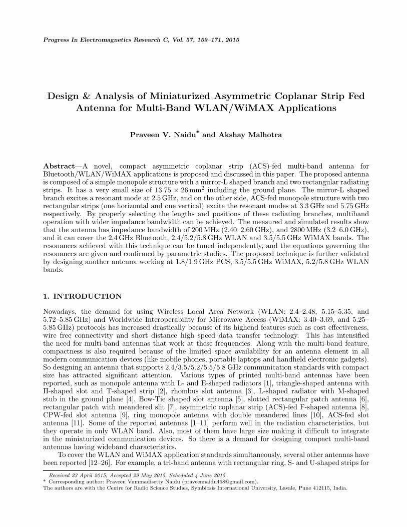
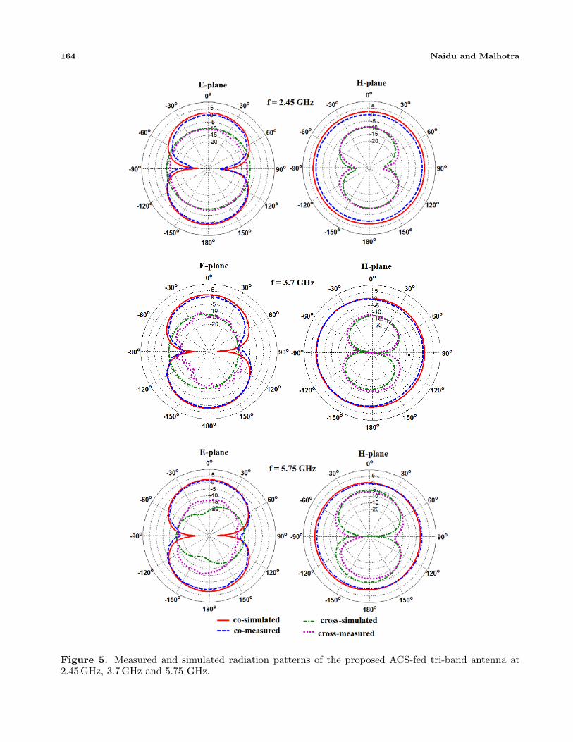
The measured far-field radiation patterns in E-plane and H-plane at 2.45 GHz, 3.7 GHz. and5.75 GHz are shown in Figure 5. A standard double ridged horn antenna is used as a referenceantenna in the antenna measurement system. Nearly bi-directional radiation patterns in E-plane andomnidirectional patterns in H-plane are observed over the operating band frequencies. The simulatedand measured radiation patterns are in good agreement, with a little difference due to measurementand alignment errors. Figure 6 shows the measured peak gains across multi operating bands. Theaverage peak gain across all the operating bands is 3.25 dBi. It can be seen from Figure 5 that theorthogonal polarization (cross polarization) at the third frequency is slightly more than those at othertwo frequencies. It can be because of the orientation of L shape which is responsible for third resonance;however, the polarization is largely determined by the ground plane just like in IFA antenna [33]. Soco-polar component still corresponds to the same polarization as at other two frequencies. The radiation

Progress In Electromagnetics Research C, Vol. 57, 2015 163
efficiency characteristics of the proposed antenna were calculated by using CST Microwave Studio. Inthe first operating band, the radiation efficiency is about 71% while in the second operating band itis about 82%. At smaller frequencies, the antenna becomes smaller than the wavelength. Hence, theantenna becomes more like a transmission line than as a radiating element. So, even when the return lossis better, the part of the energy radiated becomes less. Hence, the efficiency is less at lower frequencies.
4. PARAMETRIC STUDIES
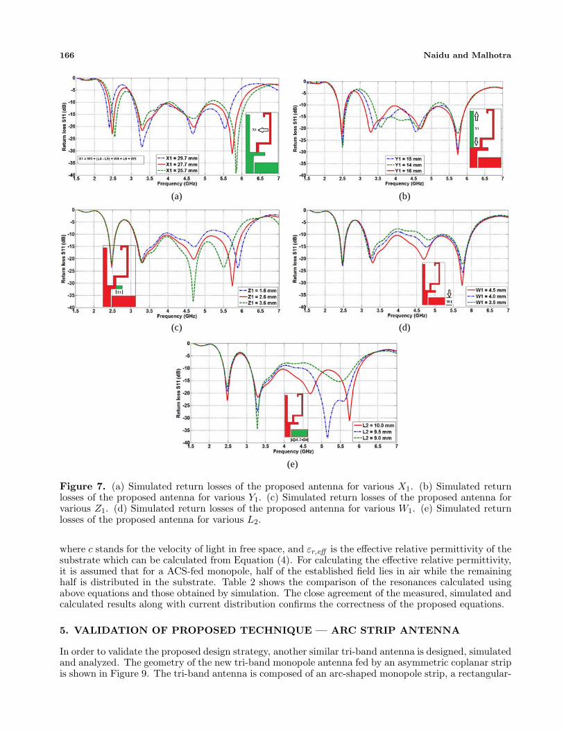
To further investigate the multi/wide band characteristics of the proposed antenna, some importantparametric studies are carried out and given in Figures 7(a), (b) and (c), respectively. The effects ofvarying the parameter X1 on return loss are given in Figure 7(a). It can be observed from the figurethat as the length of the mirror-L shape ladder branch ‘X1’ decreases, the first resonant frequencyshifts towards higher frequencies. At the same time the upper frequency limit of second operating bandslightly varies accordingly. Figure 7(b) plots the simulated return loss curves by changing the lengthof the vertical rectangular stub ‘Y1’. It can be seen that as the length decreases, the second resonantfrequency (3.3 GHz) shifts to higher side with minimal effect on the first frequency band. As a result,the overall impedance bandwidth of the second operating band decreases. Hence an optimized value ofY1 = 15 mm is considered in the final design.
Figure 7(c) describes the simulated return losses when the length of the horizontal rectangular stripZ1 varies from 1.6 mm to 3.6 mm. It can be seen that as the Z1 increases, the third resonant frequencyshifts towards lower frequencies, while the first and second operating bands are almost unchanged. Alsoit is observed that as the value of Z1 decreases the return loss near third operating band deteriorates.Hence an optimized value of Z1 = 2.6 mm is considered in the final design. From the above results itcan be concluded that the three resonant frequencies and their impedance bandwidth can be tuned andcontrolled independently by adjusting the dimensions of the parameters X1, Y1 and Z1.
The effect of the asymmetric ground plane dimensions (W1 and L2) on the proposed antennaperformance is studied and given in Figures 7(d) and (e). Figure 7(d) illustrates the simulated return
(a)
(b)
(c)
(d)
Figure 4. (a) Photograph of the fabricated prototype and comparison of simulated and measuredreturn losses against frequency. (b), (c), (d) Simulated surface current distribution of proposed antennawith cable attached (b) 2.5 GHz, (c) 3.3 GHz, and (d) 5.7 GHz.
164 Naidu and Malhotra
Figure 5. Measured and simulated radiation patterns of the proposed ACS-fed tri-band antenna at2.45 GHz, 3.7 GHz and 5.75 GHz.
Progress In Electromagnetics Research C, Vol. 57, 2015 165
Figure 6. Measured peak gain of the proposed antenna.
loss curves for different values of W1. It can be observed from the figure that with the increase ofW1, the return loss characteristics of the the second operating band are improved due to the couplingbetween the radiating element (horizontal strip) and ground plane. Similarly, Figure 7(e) describesthe simulated return losses when the length of the ground plane L2 varies from 10 mm to 9 mm. Asthe parameter L2 decreases, the return loss characteristics of the second operating band are stronglyaffected, which means that the antenna impedance bandwidth also depends on the asymmetric groundplane. Hence to achieve wider impedance bandwidth and good return loss characteristics, the optimumground plane dimensions of W1 = 4.5 mm and L2 = 10 mm are chosen in the final design.
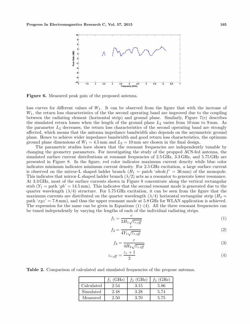
The parametric studies have shown that the resonant frequencies are independently tunable bychanging the geometry parameters. For investigating the study of the propped ACS-fed antenna, thesimulated surface current distributions at resonant frequencies of 2.5 GHz, 3.3 GHz, and 5.75 GHz arepresented in Figure 8. In the figure, red color indicates maximum current dencity while blue colorindicates minimum indicates minimum current density. For 2.5 GHz excitation, a large surface currentis observed on the mirror-L shaped ladder branch (H1 = patch ‘abcdef ’ = 36 mm) of the monopole.This indicates that mirror-L shaped ladder branch (λ/2) acts as a resonator to generate lower resonance.At 3.3 GHz, most of the surface currents shown in Figure 8 concentrate along the vertical rectangularstub (Y1 = path ‘gh’ = 14.5 mm). This indicates that the second resonant mode is generated due to thequarter wavelength (λ/4) structure. For 5.75 GHz excitation, it can be seen from the figure that themaximum currents are distributed on the quarter wavelength (λ/4) horizontal rectangular strip (H2 =path ‘xyz’ = 7.8 mm), and thus the upper resonant mode at 5.8 GHz for WLAN application is achieved.The expression for the same can be given in Equations (1)–(4). All the three resonant frequencies canbe tuned independently by varying the lengths of each of the individual radiating strips.
f1 =c
2H1√
εr,eff(1)
f2 =c
4Y1√
εr,eff(2)
f3 =c
4H2√
εr,eff(3)
εr,eff =εr + 1
2(4)
Table 2. Comparison of calculated and simulated frequencies of the propose antenna.
f1 (GHz) f2 (GHz) f3 (GHz)Calculated 2.54 3.15 5.86Simulated 2.48 3.28 5.74Measured 2.50 3.70 5.75
166 Naidu and Malhotra
(a) (b)
(c) (d)
(e)
Figure 7. (a) Simulated return losses of the proposed antenna for various X1. (b) Simulated returnlosses of the proposed antenna for various Y1. (c) Simulated return losses of the proposed antenna forvarious Z1. (d) Simulated return losses of the proposed antenna for various W1. (e) Simulated returnlosses of the proposed antenna for various L2.
where c stands for the velocity of light in free space, and εr,eff is the effective relative permittivity of thesubstrate which can be calculated from Equation (4). For calculating the effective relative permittivity,it is assumed that for a ACS-fed monopole, half of the established field lies in air while the remaininghalf is distributed in the substrate. Table 2 shows the comparison of the resonances calculated usingabove equations and those obtained by simulation. The close agreement of the measured, simulated andcalculated results along with current distribution confirms the correctness of the proposed equations.
5. VALIDATION OF PROPOSED TECHNIQUE — ARC STRIP ANTENNA
In order to validate the proposed design strategy, another similar tri-band antenna is designed, simulatedand analyzed. The geometry of the new tri-band monopole antenna fed by an asymmetric coplanar stripis shown in Figure 9. The tri-band antenna is composed of an arc-shaped monopole strip, a rectangular-
Progress In Electromagnetics Research C, Vol. 57, 2015 167
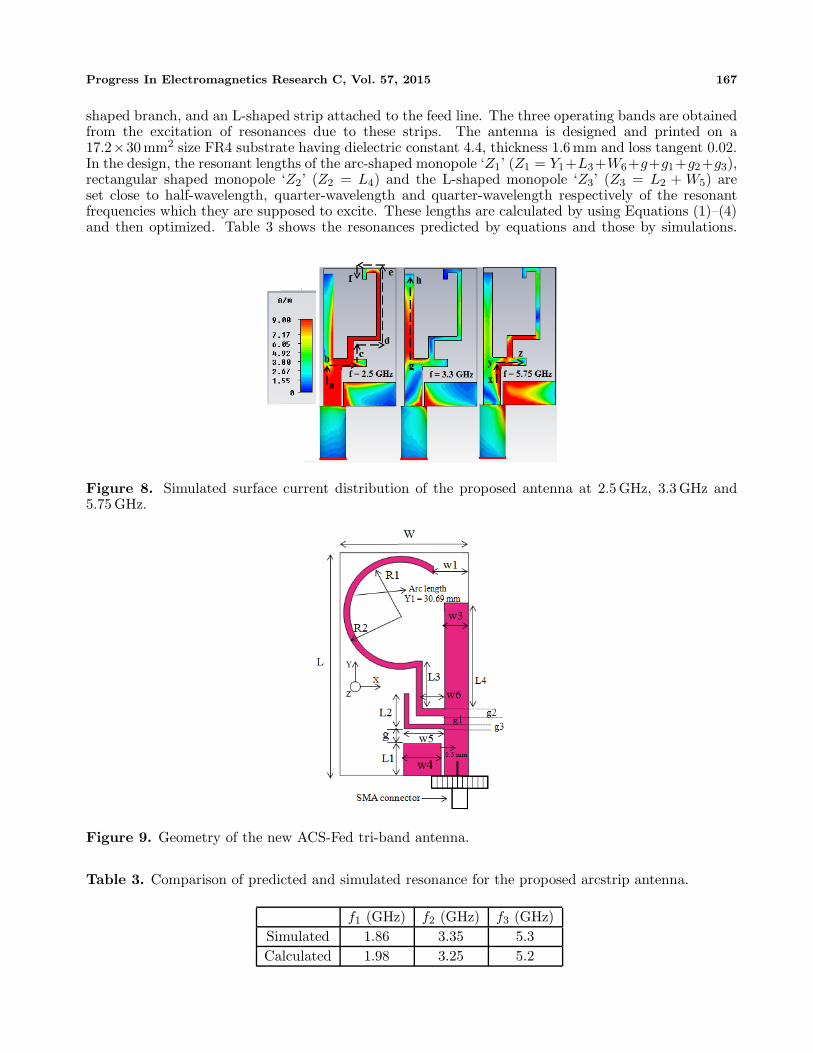
shaped branch, and an L-shaped strip attached to the feed line. The three operating bands are obtainedfrom the excitation of resonances due to these strips. The antenna is designed and printed on a17.2×30 mm2 size FR4 substrate having dielectric constant 4.4, thickness 1.6 mm and loss tangent 0.02.In the design, the resonant lengths of the arc-shaped monopole ‘Z1’ (Z1 = Y1+L3+W6+g+g1+g2+g3),rectangular shaped monopole ‘Z2’ (Z2 = L4) and the L-shaped monopole ‘Z3’ (Z3 = L2 + W5) areset close to half-wavelength, quarter-wavelength and quarter-wavelength respectively of the resonantfrequencies which they are supposed to excite. These lengths are calculated by using Equations (1)–(4)and then optimized. Table 3 shows the resonances predicted by equations and those by simulations.
Figure 8. Simulated surface current distribution of the proposed antenna at 2.5 GHz, 3.3 GHz and5.75 GHz.
Figure 9. Geometry of the new ACS-Fed tri-band antenna.
Table 3. Comparison of predicted and simulated resonance for the proposed arcstrip antenna.
f1 (GHz) f2 (GHz) f3 (GHz)Simulated 1.86 3.35 5.3Calculated 1.98 3.25 5.2
168 Naidu and Malhotra
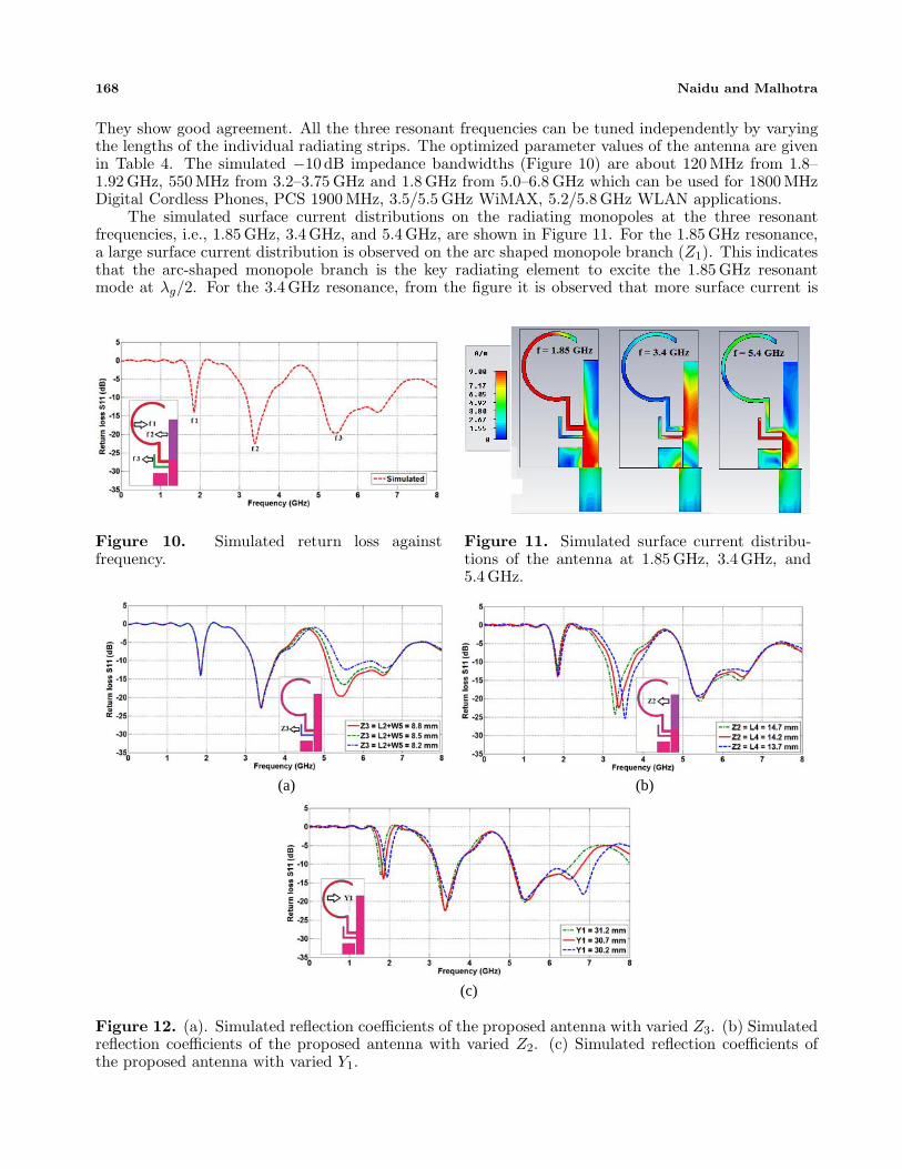
They show good agreement. All the three resonant frequencies can be tuned independently by varyingthe lengths of the individual radiating strips. The optimized parameter values of the antenna are givenin Table 4. The simulated −10 dB impedance bandwidths (Figure 10) are about 120 MHz from 1.8–1.92 GHz, 550 MHz from 3.2–3.75 GHz and 1.8 GHz from 5.0–6.8 GHz which can be used for 1800 MHzDigital Cordless Phones, PCS 1900 MHz, 3.5/5.5 GHz WiMAX, 5.2/5.8 GHz WLAN applications.
The simulated surface current distributions on the radiating monopoles at the three resonantfrequencies, i.e., 1.85 GHz, 3.4 GHz, and 5.4 GHz, are shown in Figure 11. For the 1.85 GHz resonance,a large surface current distribution is observed on the arc shaped monopole branch (Z1). This indicatesthat the arc-shaped monopole branch is the key radiating element to excite the 1.85 GHz resonantmode at λg/2. For the 3.4 GHz resonance, from the figure it is observed that more surface current is
Figure 10. Simulated return loss againstfrequency.
Figure 11. Simulated surface current distribu-tions of the antenna at 1.85 GHz, 3.4 GHz, and5.4 GHz.
(a) (b)
(c)
Figure 12. (a). Simulated reflection coefficients of the proposed antenna with varied Z3. (b) Simulatedreflection coefficients of the proposed antenna with varied Z2. (c) Simulated reflection coefficients ofthe proposed antenna with varied Y1.

Progress In Electromagnetics Research C, Vol. 57, 2015 169
Table 4. Optimized parameter values (in mm).
Parameter L W L1 L2 L3 L4 W1 W3 W4
Value (mm) 30 17.2 4.3 4.1 6.4 14.2 4.7 3.2 5Parameter W5 W6 R1 R2 G g1 g2 g3
Value (mm) 4.7 3 6.8 7.6 2 1.1 1 0.6
concentrated on the vertical rectangular shaped monopole (Z2), and very less current density is presenton the other radiating branches, implying that the resonance is because of the λg/4 length strip. Finally,at 5.4 GHz, a high current density on the L-shaped branch is observed, which indicates that the thirdoperating band of the proposed antenna is due to the λg/4 length L-shaped monopole.
To demonstrate that the resonances in this design are independently tunable, similar to the previousdesign, a parametric analysis is performed. Figure 12(a) shows the simulated return losses of the antennawhen the length of the L-shaped branch ‘Z3’ is varied. It is shown that the third resonant frequencyshifts towards higher frequencies as Z3 is decreased while the first and second bands are not affected. Asignificant effect on the return loss magnitude and bandwidth of the third operating band is also observedwhen Z3 changes from 8.8 mm to 8.2 mm. This clearly indicates that the length of the L-shaped branchdetermines the third resonant frequency of the proposed antenna. The effects of variations in the lengthsZ2 and Y1 on the return loss are studied next and given in Figures 12(b) & 12(c), respectively. FromFigure 12(b), it can be concluded that with an increase in the rectangular branch length Z2, the secondresonant frequency shifts to lower side whereas the first and third resonant modes are not affected.Similarly from Figure 12(c), it is noticed that the first resonant frequency shifts to the lower side as thearc length Y1 is increased while the second and third bands are affected slightly.
6. CONCLUSION
A technique to design very compact ACS-fed antenna for multi-band operation is proposed, discussed,and the fabricated prototype is tested experimentally. The proposed design has three different simpleradiating elements that can excite the desired resonant frequencies. The resonances are independentlytunable. The measured impedance bandwidths are about 200 MHz from 2.40–2.60 GHz, and 2800 MHzfrom 3.2–6.0 GHz. The good return loss characteristics, compact size with simple geometry, wideimpedance bandwidth with omnidirectional radiation patterns along with acceptable peak gains makethe proposed antenna a suitable candidate for 2.4 GHz Bluetooth/WiBree/Zigbee, 2.4/5.2/5.8 GHzWLAN, 3.5/5.5 GHz WiMAX, 5.9 GHz WAVE and 4.9 GHz US public safety system applications. Thetechnique is validated by designing another similar antenna operation in 1.8/1.9 PCS, 3.5/5.5 GHzWiMAX, 5.2/5.8 GHz WLAN bands. Thus, this technique can be utilized at any desired multi-band/wideband application.
ACKNOWLEDGMENT
The authors like to acknowledge vice-chancellor Symbiosis International University (DU), Pune forcontinuous support. Authors also acknowledge Rajas Khokle for his technical suggestions.
REFERENCES
1. Sun, X. L., L. Liu, S. W. Cheung, and T. I. Yuk, “Dual-band antenna with compact radiator for2.4/5.2/5.8 GHz WLAN applications,” IEEE Transactions on Antennas and Propagation, Vol. 60,No. 12, 5924–5931, 2012.
2. Teng, X. Y., X. M. Zhang, Z. X. Yang, Y. Wang, Y. Li, Q. F. Dai, and Z. Zhang, “A compactCPW-fed omni-directional monopole antenna for WLAN and RFID applications,” Progress InElectromagnetics Research Letters, Vol. 32, 91–99, 2012.

170 Naidu and Malhotra
3. Lin, C. C., E. Z. Yu, and C. Y. Huang, “Dual-band rhombus slot antenna fed by CPW for WLANapplications,” IEEE Antennas and Wireless Propagation Letters, Vol. 11, 362–364, 2012.
4. Sun, X. L., S. W. Cheung, and T. I. Yuk, “A compact monopole antenna for WLAN applications,”Microwave and Optical Technology Letters, Vol. 56, No. 2, 469–475, 2014.
5. Tsai, L. C., “A triple-band bow-tie-shaped CPW-fed slot antenna for WLAN applications,” ProgressIn Electromagnetics Research C, Vol. 47, 167–171, 2014.
6. Liu, W. C., C. M. Wu, and N. C. Chu, “A compact CPW-fed slotted patch antenna for dual-bandoperation,” IEEE Antennas and Wireless Propagation Letters, Vol. 9, 110–113, 2010.
7. Liu, W. C. and W. R. Chen, “CPW-fed compact meandered patch antenna for dual-bandoperation,” Electronics Letters, Vol. 40, No. 18, 1094–1095, 2004.
8. Deepu, V., R. Sujith, S. Mridula, C. K. Aanandan, K. Vasudevan, and P. Mohanan, “ACS fedprinted F-shaped uniplanar antenna for dual band WLAN applications,” Microwave and OpticalTechnology Letters, Vol. 51, No. 8, 1852–1856, 2009.
9. Huang, C. Y. and E. Z. Yu, “A slot-monopole antenna for dual-band WLAN applications,” IEEEAntennas and Wireless Propagation Letters, Vol. 10, 500–502, 2011.
10. Zhao, G., F. S. Zhang, Y. Song, Z. B. Weng, and Y. C. Jiao, “Compact ring monopole antenna withdouble meander lines for 2.4/5 GHz dual-band operation,” Progress In Electromagnetics Research,Vol. 72, 187–194, 2007.
11. Song, Y., Y. C. Jiao, X. M. Wang, Z. B. Weng, and F. S. Zhang, “Compact coplanar slot antenna fedby asymmetric coplanar strip for 2.4/5 GHz WLAN operations,” Microwave and Optical TechnologyLetters, Vol. 50, No. 12, 3080–3083, 2008.
12. Xu, Y., Y. C. Jiao, and Y. C. Luan, “Compact CPW-fed printed monopole antenna with triple-bandcharacteristics for WLAN/WiMAX applications,” Electronics Letters, Vol. 48, No. 24, 1519–1520,2012.
13. Naidu, P. V. and R. Kumar, “A small CPW-fed dual-band rupee shaped antenna for WiMAX andWLAN applications,” International Journal of Microwave and optical Technology, Vol. 10, No. 1,6–12, 2015.
14. Naidu, P. V. and R. Kumar, “A compact dual-band octagonal slotted printed monopoleantenna for WLAN/WiMAX and UWB applications,” Journal of Microwaves, Optoelectronics andElectromagnetic Applications, Vol. 14, No. 1, 1–13, 2015.
15. Yuan, B., P. Gao, S. He, L. Xu, and H. T. Guo, “A novel triple-band rectangular ring antenna withtwo L-shaped strips for WiMAX and WLAN applications,” Progress In Electromagnetics ResearchC, Vol. 40, 15–24, 2013.
16. Zhang, X. Q., Y. C. Jiao, and W. H. Wang, “Miniature triple-band CPW-fed monopole antennafor WLAN/WiMAX applications,” Progress In Electromagnetics Research Letters, Vol. 31, 97–105,2012.
17. Xiong, L., P. Gao, and S. X. Han, “Compact triple-frequency planar monopole antenna forWiMAX/WLAN applications,” Progress In Electromagnetics Research Letters, Vol. 34, 43–51, 2012.
18. Xie, J. J., X. S. Ren, Y. Z. Yin, and S. L. Zuo, “Rhombic slot antenna design with a pair ofstraight strips and two ∩-shaped slots for WLAN/WiMAX applications,” Microwave and OpticalTechnology Letters, Vol. 54, No. 6, 1466–1469, 2012.
19. Liu, Z. Y., Y. Z. Yin, S. F. Zheng, W. Hu, L. H. Wen, and Q. Zou, “A compact CPW-fed monopoleantenna with a U-shaped strip and a pair of L-slits ground for WLAN and WiMAX applications,”Progress In Electromagnetics Research Letters, Vol. 16, 11–19, 2010.
20. Zhao, Q., S. X. Gong, W. Jiang, B. Yang, and J. Xie, “Compact wide-slot tri-band antenna forWLAN/WiMAX applications,” Progress In Electromagnetics Research Letters, Vol. 18, 9–18, 2010.
21. Ren, X., S. Gao, and Y. Yin, “Compact tri-band monopole antenna with hybrid strips forWLAN/WiMAX applications,” Microwave and Optical Technology Letters, Vol. 57, No. 1, 94–99,2015.
22. Ren, F. C., F. S. Zhang, J. H. Bao, B. Chen, and Y. C. Jiao, “Compact triple-frequency slotantenna for WLAN/WiMAX operations,” Progress In Electromagnetics Research Letters, Vol. 26,

Progress In Electromagnetics Research C, Vol. 57, 2015 171
21–30, 2011.23. Song, Y., Y. C. Jiao, G. Zhao, and F. S. Zhang, “Multiband CPW-fed triangle-shaped monopole
antenna for wireless applications,” Progress In Electromagnetics Research, Vol. 70, 329–336, 2007.24. Naidu, P. V. and R. Kumar, “Design of a compact ACS-fed dual band antenna for
Bluetooth/WLAN and WiMAX applications,” Progress In Electromagnetics Research C, Vol. 55,63–72, 2014.
25. Chen, H., Y. Z. Yin, and J. Wu, “Compact tri-band meandered ring monopole antenna with twoembedded strips for WLAN/WiMAX applications,” Progress In Electromagnetics Research Letters,Vol. 45, 63–67, 2014.
26. Li, B., Z. H. Yan, and T. L. Zhang, “Triple-band slot antenna with U-shaped open stub fedby asymmetric coplanar strip for WLAN/WiMAX applications,” Progress In ElectromagneticsResearch Letters, Vol. 37, 123–131, 2013.
27. Li, Y., W. Li, and R. Mittra, “A compact ACS-fed dual-band meandered monopole antenna forWLAN and WiMAX applications,” Microwave and Optical Technology Letters, Vol. 55, No. 10,2370–2373, 2013.
28. Li, Y., W. Li, and R. Mittra, “Miniaturization of ACS-fed dual-band antenna with loadedcapacitance terminations for WLAN applications,” IEICE Electronics Express, Vol. 10, No. 15,20130455–20130455, 2013.
29. Li, Y., W. Li, and Q. Ye, “A compact asymmetric coplanar strip-fed dual-band antenna for2.4/5.8 GHz WLAN applications,” Microwave and Optical Technology Letters, Vol. 55, No. 9, 2066–2070, 2013.
30. Liu, Y. F., P. Wang, and H. Qin, “A compact triband ACS-fed monopole antenna employinginverted-L branches for WLAN/WiMAX applications,” Progress In Electromagnetics Research C,Vol. 47, 131–138, 2014.
31. Deepu, V., R. K. Raj, M. Joseph, M. N. Suma, and P. Mohanan, “Compact asymmetric coplanarstrip fed monopole antenna for multiband applications,” IEEE Transactions on Antennas andPropagation, Vol. 55, No. 8, 2351–2357, 2007.
32. Ashkarali, P., S. Sreenath, R. Sujith, R. Dinesh, D. D. Krishna, and C. K. Aanandan, “A compactasymmetric coplanar strip fed dual-band antenna for DCS/WLAN applications,” Microwave andOptical Technology Letters, Vol. 54, No. 4, 1087–1089, 2012.
33. Zhang, Z., Antenna Design for Mobile Devices, John Wiley & Sons, 2011.