design analysis of a friction disk rotor
TRANSCRIPT
DESIGN ANALYSIS OF A FRICTION DISK ROTOR/
By
DIXON KEITH FOSS ,,
Bachelor of ·science
Oklahoma State University
1962
Submitted to the faculty of the Graduate School of the Oklahoma State University
in partial fulfillment of the requirements for the degree of MASTER OF SCIENCE
August, 1964

I OKLAHOMA ll'AT£ UNIVERSITY
LIBRARY .
JAH5 ~5
\
DESIGN ANALYSIS OF A FRICTION DISK ROTOR
Thesis Approved:
569550 ii

TABLE OF CONTENTS
Chapter Page
I. INTRODUCTION • • • • • l
General Statement of the Problem. • • • • 2 History • • • • • .. • • 3 Literature Survey • • • • 7
u. MATHEMATICAL ANALYSIS • • • • • • • • • • • • • • • • 9
Linearized Solution • • • • • • • 12 Numerical Solution • • • • • • • 16
III. TEST FAN DESIGN AND INSTRUMENTATION • • 21
IV. EXPERIMENTAL RESULTS • • • • • • • • ... • • • 28
v. APPLICATION OF DESIGN INFORMATION. 36
General Design Method • • • • • • 36 Example Problem • • • • • • • • • 40
VI. CONCLUSION • ·• • • • • • • 43
BIBLIOGRAPHY • • • • • • • • • • • • • • • • • • • • 45
APPENDIX A • • • • • • • • • • • • • • • • • • • • • • • • • 46
APPENDIX B • • • • • • • • • • • • • • • • • • • • • • 51
iii

LIST OF TABLES
Table Page
I. Disk Fan Data. • • 47
II. Fan Power Requirement . • • 48
III, Rotor Performance . • • •· 50
IV. Rotor Efficiency • • • • • • 50
iv

LIST OF FIGURES
Figure Page
1. Patent Drawing, Fluid Pump . . . . . . . . . . . . . . . . 4
2. Patent Drawing, Turbine •• • • • • • • • • • • • • • • • • 5
3. Mathematical Model, Co-ordinate System . . . . . . . . . . 10
4. .a(
Effect of Distance Parameter on the Ratio~ . . . . . . . 15
5. Mathematical Model, Dimensionless Co-ordinate System • • • 16
6. Performance Curves From Linear and Non-Linear Solutions • • 18
7. Efficiency Curves From Non-Linear Solution •••••••• 20
8.
9.
10.
11.
12.
13.
14.
15.
Details of Disk Design . . . . . . . . . . . . . . . . . . Test Fan Side View • • • • • • • • • • • • • • • • • • • •
Test Fan Front View . . . . • • . . . . . . . . . . . . . . Efficiency Curves From Test Fan . . . . . . . . Performance Curves From Test Fan and Analytical
Solutions, r :: 3.06 ••••••••••••. •
. . . . . .
. . . . . . Performance Curve From Test Fan and Analytical
Solutions, r: 2.0 ••••• • ••••••• . . . •· . . Axial Flow Distribution . . . . • • • • • • • • • • . . . . Effect of Distance Parameter on Test Fan Efficiency . . . '
. 22
23
24
29
30
31
33
33
16. Solution of Linear Pressure Equation ••••••••••• 39
17. Fan Power Requirement ••••••••••••••••••• 49
18. Schematic for Inlet Error Calculations . . . . . . . . . . 52
V

d
~ HP
M
n
p
Q
r' r
s
u (or U)
Uo (or U.> V
V
.iJ
w
w X
y
C.
LIST OF SYMBOLS
1/2 Disk Spacing
Rotor Efficiency
Horsepower
Torque
Number of Disks
Pressure
Volume Flow Rate
Fluid Density
Radial Distance
Disk Spacing
Radial Velocity
Radial Velocity at Inlet
Tangential Velocity
Reiative Tangential Velocity
Fluid Kinematic Viscosity
Axial Velocity
Angular Velocity of Disks
Radial Distance, Transformed co-ordinates
Axial Distance, Transformed Co-ordinates
Axial Distance
vi

i
e
s
d
SUBSCRIPTS
Condition at Disk Port Radius
Condition at Outer Disk Radius
Superscript, Dimensionless Variable
Static Condition
Dynamic Condition
vii

CHAPTER I
INTRODUCTION
The purpose of this investigation is to obtain design information
on a friction disk rotor. At the present time there is no information
from which a rotor of this type can be easily designed to deliver a
given quantity of air at a given pressure. A knowledge of the design
requirements of the rotor would lead directly to the design of a
complete fan unit. The complete fan consists of the rotor and the
housing, which includes the inlet and diffuser sections. Because the
housing design would be similar to that of any centrifugal fan this
subject has not been covered in this study. Information pertaining to
efficient housing design is readily available; two sources have been
cited [3], [11)1.
Although this study has been limited to the use of air as the
working fluid any other fluid could be used by substituting the
appropriate values of density and viscosity.
This study includes the results of a mathematical solution by
Pohlhausen and Breiter [2], from which the performance characteristics
are derived. An experimental fan was built and tested in order to
compare the characteristics of a practical design with those of the
ideal model in the mathematical analysis.
!Numbers in brackets designate references at end of paper.
1

The report is conclude.d with a summary of the results and an
outline of design methods. The outline includes specifications of
all the critical dimensions of the rotor from given flow conditions
and fluid properties.
General Statement of the Problem
A friction disk rotor differs from conventional vane type rotors
in its manner of energy transfer. Just as the name implies, viscous
friction is the sole means of energy exchange •. ·
2
In order to explain the method in which viscous friction is
employed let us consider a flat plate which is being moved through a
fluid medium. The particles of fluid on the solid surface will move
with the velocity of the plate as required by the condition of zero
veiocity at a solid boundary. The velocity gradient between these
particles and the adjacent fluid layer will create a shear force which
will accelerate the fluid. The net result of this shearing action
·between adjacent fluid layers is an acceleration of the fluid mass in
the direction of motion of the plate. The amount of acceleration
depends upon the velocity gradient so that fluid layers more distant
from the plate will be affected less by the motion.
It can be seen that some of the energy required to move the plate
through the fluid appears as kinetic energy in the fluid particies near
the plate. Thus the motion of the plate exerts a pumping action on the
fluid due to the viscous shearing forces between adjacent layers of the
fluid.
The pumping action can be realized in a practical case if the
plate is considered to be a series of disks mounted on a rotating
3
shaft .and. se.parated .by smal.l gaps. The fluid in the .gap between each
disk will be accelerated in the tangential direction by the shearing
forces in the fluid. The rotation of the fluid about the axis of the
shaft will result in an outwardradial acceleration. If the fluid is
allowed to enter through P<?rts in the disk near the shaft a radial
flow will exist. The pressure developed by the pump will depend upon
the radial acceleration which is obviously a function of the tangen
tial velocity.
An important point now arises which affects the efficiency of
any machine operating on the friction disk principle. The radial
velocity which exists due to an outward radial flow of fluid. between
the disks is also subject to the condition of zero velocity at the
solid boundary. This condition now represents a loss of energy. The
shearing forces retard the flow of fluid in the radial.direction and
produce a radial force in the disk. This force is the same at all
points equidistant from the center of the disk so that it appears only
as an internal force in the disk. Thus the efficiency of the friction
disk pump will depend upon its ability to accelerate the fluid to a
high tangential velocity and will be limited by the amount of energy
which is lost as the fluid flows in the radial direction. Thus it
appears that the efficiency will decrease as the radial velocity
increases.
History
The friction disk principle was first used by Nikola Tesla in
1905. He received patents on a pump and a turbine which utilized the
principle (Figs.land 2) in 1913.
Most of his work was directed toward development of a steam

Fig, 1
N. TESLA. FLUID PROPULSION.
Arl'LIOATION FILED OOT. 21, 1909.
1,061,142. PatentedMay 6, 1913.
l O O O O
-------- 0 ----
Jf~ J' tP,Q.,, . · clwoe~
~'Jiu cl.-t-to-t:ne~d .
·4; 4-,_,,4_~ ~~
4
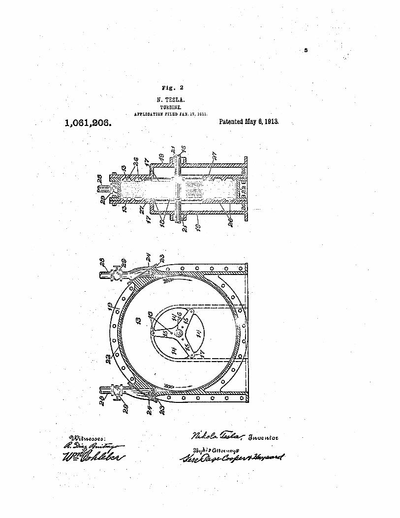
Fig. 2
N. TESLA, TURBINE,
Al'l'LJOATIOll lILJlD JAIi, 17, 1011,
1,061,206, Patente4 May 6, 1913.
',/.,
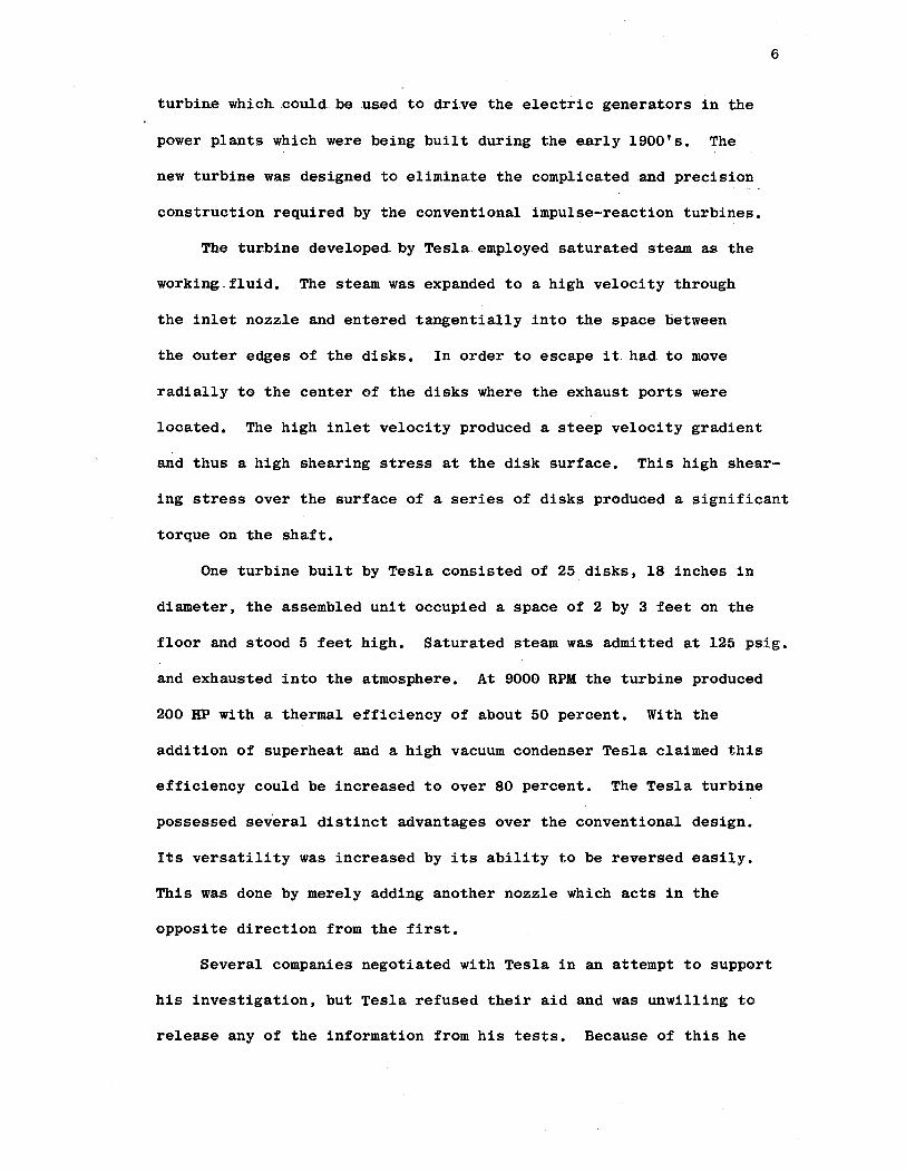
turbine which could be used to drive the electric .g.enerators in the
power plants which were being built during the early 1900's. The
new turbine was designed to eliminate the complicated and precision
construction required by the conventional impulse-reaction turbines.
The turbine developed by Tesla employed saturated steam as the
working. fluid. The steam was expanded to a high velocity through
the inlet nozzle and entered tangentially into the space between
6
the outer edges of the disks. In order to escape it had to move
radially to the center of the disks where the exhaust ports were
located. The high inlet velocity produced a steep velocity gradient
and thus a high shearing stress at the disk surface. This high shear
ing stress over the surface of a series of disks produced a significant
torque on the shaft.
One turbine built by Tesla consisted of 25 disks, 18 inches in
diameter, the assembled unit occupied a space of 2 by 3 feet on the
floor and stood 5 feet high. Saturated steam was admitted at 125 psig.
and exhausted into the atmosphere. At 9000 RPM the turbine produced
200 HP with a thermal efficiency of about 50 percent. With the
addition of superheat and a high vacuum condenser Tesla claimed this
efficiency could be increased to over 80 percent. The Tesla turbine
possessed several distinct advantages over the conventional design.
Its versatility was increased by its ability to be reversed easily.
This was done by merely adding another nozzle which acts in the
opposite direction from the first.
Several companies negotiated with Tesla in an attempt to support
his investigation, but Tesla refused their aid and was unwilling to
release any of the information from his tests. Because of this he

lost .much of his financial hacki.ng and was forced to discontinue. his
tests in 1925. Until recently very little interest has been shown in
the friction disk principle. Since 1958 several groups have investi
gated the principle with varying degrees of success. Here ag.ain most
of the testing has been directed toward the operation of the turbine
rather than the pump. A summary of the results of several investi
gations is given in the next section.
Literature Survey
Rice [7] presents a summary of test results from a water pump
7
and an air blower using multiple disk rotors. He also gives a first
approximation mathematical analysis of the performance of such machinery.
No attempt is made in the discussion to compare the experimental
results with the analysis.
The water pump which was tested contained 34 disks, 5.0 inches
in diameter. They were .020 inches thick and spaced .020 inches apart.
The inlet was 1.0 inches in diameter and contained no shaft or other
obstructions. The disks were supported by eight small throughbolts and
an inlet spider at each side. Water entered from chambers in the pump
housing, through the inlet spiders, into the central hollow portion of
the rotor and finally into the spaces between the disks •.
The efficiency was defined as the ratio of the increase in the
hydraulic energy of the fluid through the pump to the shaft work
supplied to the pump. The maximum efficiency reported for this unit
was in the order of 20 percent.
The mathematical analysis was carried out by applying certain
idealizations and assumptions to the Navier-Stokes equations. The

final results of the analysis agree closely with the linearized
solution shown in the present paper. However, one important de.sign
parameter did not show up in the analysis. This parameter relates
the disk spacing, the fluid kinematic viscosity and the angular
velocity. In the present paper this parameter is found to be the
key to determining the optimum design.
The investigation by Beans [1] was very similar to that of Rice.
The mathematical approach was different but the results were similar.
The lack of the design parameter discussed above limited the useful
ness of the results.
The study by Hasinger and Kehrt [s] employed the results of the
work by Breiter and Pohlhausen [2]. Their test apparatus was a water
pump with the disks built in the shape of cones rather than flat as
in most cases. This design produced a more rigid disk and reduced
the inlet angle through which the fluid had to turn from the axial
to the radial direction. The reported efficiency was near 60 percent
and was defined as the total head gain divided by the sum of ideal
pump head and the rotor-housing friction loss.
8
CHAPTER II
MATHEMATICAL ANALYSIS
This analysis is based on the .results of a report by · Pohlhausen and
Breiter [2]. Their report investigates the viscous flow between two
parallel disks which rotate with the same constant angular velocity in
the same direction. T~e analysis determines the velocity distribution
between the disks, the pressures, the torque applied at the shaft, and
the resulting efficiency.
The problem was approached by applying the boundary layer assumptions
to the equations of fluid motion (Navier-Stokes equations). Practical
considerations justify this approach. The distance between the disks
must be very small in order for viscous forces to produce a significant
tangential flow. This assumption allowed the Navier-Stokes equations to
be reduced to a system of parabolic differential equations.
The problem is described by a system of cylindrical co-ordinates as
shown in Fig. 3. The Navier-Stokes and continuity equations which
describe the i.mcompressible, a,xi-symmetric, steady 9 viscous flo~ are as
follows:
u EY. T VI u + u v- - -v f? i- -u fr:< f) .,. 'D r r:J. Jr JZ -r- -
9

r
t
~ _w (--~-+---,-+---l---------·
""" 0 "'"'
r
FIG. j
SCHEMATIC DIAGRAM OF
THE FLOW BE'l'WEEN TWO
ROTATING DISKS
10

I['' --r
Introduction of the boundary layer approximations resµlts in the
omission of the equation of motion in the axial direction. The system
of equations is now reduced to iVuE + ~g_ + uv = 1)~).
Jr dz r r:1
Jd_ +r
V'' - -r
For convenience the tangential velocity v of the fixed co-ordinate
system is now transformed to the tangential velocity V relative to the
disks
V= v-rw With this single transformation all velocities are now considered to
be relative to the disks.
Introducing this transformation into the above expressions yields:
11

12
[r)V ~ dV U (V r rw] /V (t2.. I) u Jr + 6) + w-sz + - Vu, -r
vl. +;E. v rCJ + r 1~" _J. JP 1.
u~ + w' JU - 1) JU (i.~) = + d~:I.. ;Jr ;;J~ r f' ;; r
dl./ + Jd.. dw' = 0 (2.3) - + d-r r ;)Z.
The boundary conditions along the disks are given by
u(r,±d)= o
V( r J ± d) = O
'w(ri :r. d)= o And the velocity distribution at the entrance cross section is given
by U ( (;· J t) = Uo
v(t;: ~)= -rcJ
'vi ( t.: 1 Z) = 0 The solution of this non-linear system is now presented in two
parts. The first part introduces assumptions which linearize the
above equations and leads to a useful solution. These assumptions
are not valid in the immediate neighborhood of the inlet region.
Thus the second part is concerned with a numerical solution of the
system near the inlet.
Linearized Solution
If it is assumed that the fluid velocities relative to the disks
are small then quadratic terms involving these velocities can be

13
neglected. This condition is satisfied at all radii except near the
inlet and results in a linear system which can be solved by standard
techniques. The solution is considered to be an asymptotic expression
for the actual system.
When the quadratic terms in U, V, and Ware omitted from equa-
tions (2.1) and(2.2) the following expressions result:
(t?. 4)
-+ ~ V = I -t<Jl) - rw (~.5)
The boundary layer assumption that the pressure does not depend upon
Z allows equation (2.5) to be written in the form
1) - + 2 V = F(r) (2.6)
Equations (2.4) and (2.6) can be solved with the aid of the initial
velocity and boundary conditions and the continui ty equation (2.3).
It is found that the velocity profil es are governed by one
dimensionless quantity which we will call the dis t ance parameter.
This parameter contains the angular velocity, the kinematic viscosity,
and the distance between the disks. I t is given by
For the purpose of this investigation the most important results
involve the determination of the pressure gradi ent . This is found to
be dP -dt f°<.J [r~ - J (~.7)

14
/3 = 5/NH r~ d) 5/N (2. a) CO.SH (2. a) + cos (2 d)
where
and Q is the volume flow rate which is given by
Q = 4 TT cl t lJo ( F2. 8)
Equation (2.7) can be integrated to yiel d
~ -e = Q ~ (.!1.) 7T /3 C: (a.. 9)
For simplicity the pressure, radius, and veloci ty terms can be non-
dimensionalized:
- p Uo Lio r= Ct p = 1°0a. r,~ - -t: 0 r,.
;A., ;,(,
Inserting these into equations (2.8) and 2. 9) yields
F's I -a. Q - - < r -1) Ln r (2.10) 2.. 7T 1::,:~. V 0 V ~
Q= 4TT d CJ t/ Uo (i.11) where Psis the dimensionless static pressure r i se ac ross the disks.
Upon combining (2.10) and (2.11) and introducing t he parameter d, we
find that the pressure can be expressed in t erms of the radi a l inl et
velocity by
- I -2 ~ = - ( r -1' -s 2. I ('2.li?)
This equation can be used to calculate the pressure r i se for a given
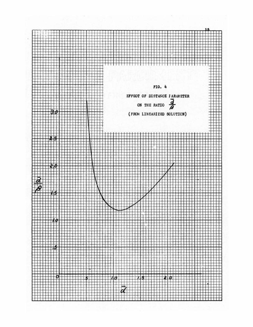
flow rate and rotor size. The maximum pressure will of course depend
upon the value of the . cl ratio ,8 ·. This ratio is shown in Fig. 4 as a
function of a. It is apparent that the maxi mum pressure wil l be
obtained when the value of dis 1.1, the corresponding value of
I l ,- -,,--1 - ' - 1 I - ·
--·· . - - ,- - -~---- -~
,
--..........
.. FIG • 4 -- -- -1--
EFFEO-T OF DISTANCE f ARAME'l'ER
l. ON THE RATIO ~ ... I
,I (FROM LINEARIZED SOLUTICN) I
• . .
-
" I I I
v I/ ,,
~ ,_, ,., I .. ... .. ... ,,
" ' •I• " ..
' '- ,, " - ""' ,--
I •
--
. ---..
,_ _ _ ,_
... ... " z, '. • j}
-I [..ii
-
16
is 1.17. This optimum value of the distance parameter is very
important in the rotor design as it defines the relationship between
the fluid viscosity, the disk spacing and the speed.
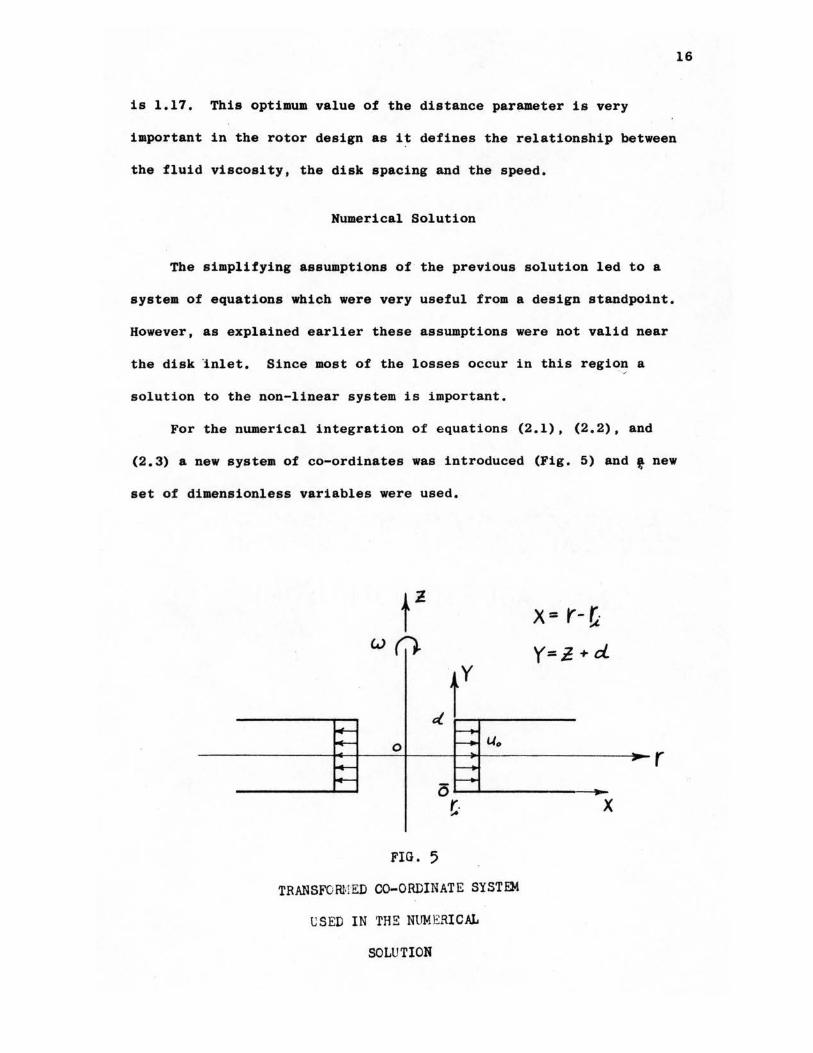
Numerical Solution
The simplifying assumptions of the previous solution led to a
system of equations which were very useful from a design standpoint.
However, as explained earlier these assumptions were not valid near
the disk inlet. Since most of the losses occur in this regio~ a
solution to the non-linear system is important.
For the numerical integration of equations (2.1), (2.2), and
(2.3) a new system of co-ordinates was introduced (Fig. 5) and f new
set of dimensionless variables were used.
t'! (.J Ci}
· y
J 0 Uo
0 r. ;...
FIG. 5
TRANSFORMED CO-ORDINATE SYSTEM
USED IN THE NUMERICAL
SOLUTION
X = r- ft Y=~+d
X
V= L r.. CJ ""'
- kt W= VvCI
17
-X = r::: I+ X
Introducing these new variables into equations (2.1), (2.2), and (2.3)
the following system is obtained:
- ;;u - d a -r v_ ,l u dX +-w'W -v l+X +~ - F(F)
-[~ L 1., Jv u Jx ., l+x + ~] + w )'Y
.lJJ. -f _y_ + J 'w - 0 ;;x 1+x )7 -where
dP at
The boundary conditions now become
Ll(XJO)=O
v(x, o)= o
i:;;( x~ o) = o
JQ (~ cl) J9
JV(x,c/)
)9
- 0
- 0
This system of equations was solved by Breiter and Pohlhausen
using a modified 'inverse' difference procedure, and the results were
shown in graphical form. Fig. 6 shows the dimensionless pressure
versus radial inlet velocity for dal.O with r as a parameter. The
solid lines are from equation (2.12) and the dashed lines represent
the non-linearized solution. The solution of the non-linearized
problem was shown by Breiter and Pohlhausen in a pl ot of pressure

.... FIG. 6 " "
' fERF0.11-'.ANCE CL'RVES FIDM LINEAR
"" - AND NON-LINEAR SCLL'TIONS , - ' ' LIN EAR SOLUTION
' -.... '' "- -----NON-LINEAR SOLUTiuN ' , ... , ..... -.. " d•1.0
r,.. .... 1' , .... .....
"' ,~ , ... -- 1'. " .. N " ..... ~ .... .... L, [ r
' ..... ~ ' ..... - • , ,1 I
"' I '- " '"' , .. . , .... I " ' ' " LJ ::: ... I .. ..... I' " I ..... 1'. I', ' I',
I "' ' .... "' ,~ ..... ·- , ... ..... .... " - " ' ....
I "' ' • • " , ... '"
" " ..... I • I .I ,.. " I I',
It , "' .... , I ' I "' "' •I'- '"' I l"",l .... ,..,
" .... I i.... ..... " ..... ~ r, , ... , ..... " " ... "
.... I ' " I "" K .... I I ' I l , ... .. ·'" I ... ' ..... "" .... P, ' .. ' - " .... "' ...._
"' " I I', ... " - .... '" '"' ""' .... .... ...... .. ,......, ...._ I " .. • I ' ' , .... I
~ ,. i,: ........ , ' ' I .. t, .... I .... I ' "" ..... ... ~ . .... I " .... ' . ..... ,..,_ " .. .... "- I ...... , ... .... ~ .. ... " "' ~--- 1\1 - .... ""
, ..... 1' .. .. , ... " i " . " I ... ..... , ... . ... ,.. ..... • . I . "' ..... .... . ..... "" --- I • ,... 1 " ' I' , - , ..... . ,- , ... - .... ,... .. . 1 ' N - .... .... " "
,~~ I - . ..... , I I t r-,,,.. I I ,._ I I I I I I I
l ~ If. I I I I) I I/ II 111; Ill• ,,,,
~ ~ I I ~
:ir,
I '- I I I
I

19
gradient versus r with 00 as a parameter and d=l.O. Graphical integra-
tion was therefore necessary to produce the dashed curves of Fig. 6.
The rotor efficiency is defined by
Q
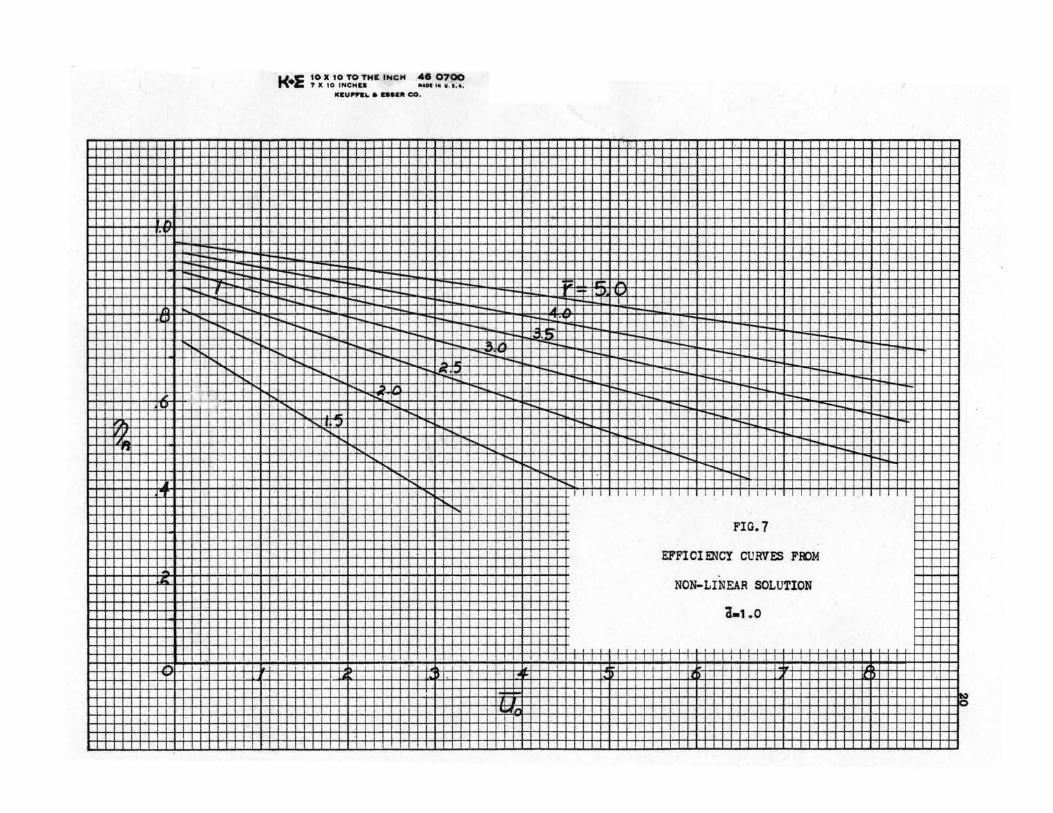
Fig. 7 shows the rotor efficiency as a function of 00 with r as a
parameter.
t<•E
"I
- --·-- ---... - ---, - - -"
,... , .... ,..
, .... ,... r,
,....
" -...... ·- r,
" • '-· r,
"' ' -. '
••
I
I
10 X 10 TO THI: INCH .... 0700 7 X 10 INCH&• •AH IN w. I, a,
1esul"PS1. • nas• co.
,--- ---.... r--r-- ' ---- - -- - I• ,... '" ·-, .... T"-
Ir ' T"-
,-I ' ' - ....
, .... ....
.... r,.
" I" I I
.... r,.
I I
--I r- ....
l " -
.... ....
- . ... -- -t -LA ...... ---- --- ,~ . J ,-r--- -- - --,- ... -- ,--r-- -.... ,--- - -- I ,-
,- ,-I ,-- ,... -- ,..
- -..... - ,-- .... .... -- --I I I I I
FIG.7
EFFICIENCY CURVES FK>M
NON-LINEAR SOLUTION
a.1.0
~ ' I ' I I I . -~ ' J l. J
,__ -.... - i,,

CHAPTER II I
TEST FAN DESIGN AND INSTRUMENTATION
A friction disk fan was built and tested in order to check the
design parameters and performance which was predicted by the analysis
in the previous chapter.
The fan consisted of a set of disks mounted on a shaft and
surrounded ;by a plastic housing (Figs. 8-10). The function of the
housing was to provi de a means of controlling the outlet pressure.
The efficient diffusion of the fluid stream was not an important
factor in the design of the test fan because onl y the rotor section
was being studied.
The housing was designed with the air inlet on one side and the
driving motor on the other side. A more pract i cal design would admi t
air from both sides but the single inlet arrangement was desired for
test purpos es. This was done so t hat the flow restriction in the i nl e t
ports could be studied, as will be discussed later.
The most critical points in the fan design were the disks them=
selves and the seal between the housing and the first disk. To
obtain satisfactory disks a material had to be selected which was of
uniform thickness and stiff enough to remain absolutel y flat after
the machining operations, The requirement that the dislc be flat and
parallel is demonstrated by the dependence of don the distance
between adjacent di sks.
21

FIG. 8
Dh'l'AilS OF DISK DESIGN
r•3.o6
22

23
TOTAL PRESSURE OUTLEr PRESSURE
DISKS
MOTOR
FL(llJ·NOZZLE
FIG. 9
TEST FAN SIDE VIEvv

FIG. 10
TE3T f J.N FRONT VIE'N
24
ourLET
ourLE'r PRESS.URE
DISK

25
The disks used in the tests were made of 0.056 inch acrylic
plastic. This material was of uniform thickness but was not as flat
as desired. The disks had to be held parallel by placing. small spacers
at the outer radius. In order to reduce the pressure loss at the seal
between the housing walls and the adjacent disk, a solid disk was used
at the motor end of the fan and a special wall was built which could
be positioned very carefully at the inlet side.
Two sets of disks were used in the test fan. The outside
diameters were held constant at 5.2 inches and the inside diameters
were 1.7 inches and 2.6 inches resulting in radius ratios of 3.06
and 2.0 respectively. The total area of the inlet ports was reduced
in each case by the presence of the shaft and the disk spokes. The
disk spacing remained constant at o.025 inches throughout the testing
program. The value of a was controlled by the speed of the driving
motor.
Internal stresses in the ·material caused by the high rotational
speeds were never a significant problem and were calculated by treating
the disks as spoked flywheels.
The flow rate was measured at the fan inlet with an A.s.M.E. flow
nozzle.
To calculate the rotor efficiency it was de$ired only to measure
the power necessary to pump the air through the rotor2. Thus the p~wer
requirement would be zero when the flow rate was zero. The fan was
2All losses external to the rotor, e.g. motor efficiency, housing to rotor friction losses, were not included in this efficiency.

26
driven by a 6 volt D.c. motor which was controlled by a variable volt
age power supply. The power input was measured by the current and
voltage supplied to the motor. Bearing friction and viscous losses
between the solid wall and the first moving disk were carefully held
constant during each test. Therefore they would cancel out in the
calculations. A typical power requirement curve is shown in Appendix A,
Fig. 17. In this figure the above mentioned losses control the position
(height) of the curve and the power required by the rotor determines
the slope of the curve. Thus to calculate the rotor efficiency only
the slope of the curve is necessary.
The mathematical analysis required that the pressure measurements
be made a~ points between the disks at the inner and outer radii. This
requirement was quite difficult to satisfy because of the rotation of
the disks and the size of the gap between them. It was therefore
necessary to make all pressure measurements outside of the disks
(Fig. 9).
The inlet static pressure was measured at a point in the wall of
the inlet port. The pressure here can be corrected to the actual
inlet pressure by considering two faotors 3• First, the differenoe in
the flow area between the inlet and _the disk gap will cause a velocity
change which will influence the pressure. The influence of this area
difference was calculated and found to be small, so it was neglected.
The second factor concerns the tangential velocity increase due to
the rotation of the disk spokes. It was not possible to measure the
extent Qf the velocity increase due to this factor in tlle test. fan.
3These calculations are shown in Appendix B.
27
The calculations show that a significant correction would be necessary
if the air velocity approached the velocity of the disks before it
entered the gap.
The outlet static pressure was measured at a point in the
housing wall and as close to the edge of the disks as possible. The
outlet dynamic pressure was measured with a total head probe. This
probe could be positioned directly over the disk gap and rotated to
determine the maximum pressure. The dynamic pressure measured by
this probe was an average value because the opening in the probe was
the same size as the disk gap.
A correction factor at this point would be determined by the
amount of diffusion which took place between the disk outlet and the
measuring points. The diffusion in this case was neglected because
of the high exit velocity and the short distance between the disks and
the measuring instruments, (Figs. 9 and 10).

CHAPTER IV
EXPERIMENTAL RESULTS
The material presented in the mathematical analysis indicated
that the friction disk rotor is capable of achieving high values of
efficiency. The real test of the friction disk principle is whether
this efficiency can be realized in a practical design.
Fig. 11 shows the efficiency of the test rotor as a function of
U0 • This can be compared to Fig. 7 from the analysis. The perform
ance curves are shown in Figs. 12 and 13 for both the experimental
and analytic results. From this information it can be seen that the
fan does have a reasonable efficiency but there is still a consider
able amount of improvement which can be made.
Tb.ere are two factors which should be considered when accounting
for the losses indicated in these figures. These factors are pressure
losses due to obstructions in the flow pattern, and uneven axial
distribution of the flow.
Before looking into these points it would be well to review the
assumptions which were made in the mathematical analysis. The mathe=
matical model consisted of two flat parallel disks with a circular
inlet at their center. The fluid was assumed to enter the region
between the disks with zero tangential velocity and a uniform radial
velocity u9 • The pressure rise was taken as the difference of the
static pressures at the outer radius and the inner radius. All three
28

·r-----f-------11 __ [+w1 I I-JI' --+j-- _l..l--j-+--l~-1-~+ l~r+i-1---,-- , __ _ Rn--- -T - --iT +J-rt-f -ri --IT . -r- -+ -- -L - - --- - - - ,_,_ - - -- ---
•-+-+-+-·t-+-·•- - -- -l-- - - .:__ l r----r·-tt·~n=-d~.J'=. :tT :--l-~=,~--~--;H-+--l-+-l-++--1- -+-+--l-t-J--1--IH-H l-+--t-+-+-f-+-l--+--1-l--l-'-l--l--l--,1-,!--I- --1--t-r-H-- · -+ -l- !-'--t·-/--4- .- -f-! ·-'- -f-1- \ --- - -t--1--1--1-1--1-1--1--+-i 1--1-+-+-;-+-+-+-+-+-t--f--+-+--1-1-+-+---- ---1+ + --1-1-,-.--1-- r- -1-' --•-<-+--+-t-+-->--+-!f--1--i!--+-t--+-t--+-J-,_,== =ttc:I=-= = ± ~wJ t~j.:..~- ·-- =~ :±t = H--e-1-H-1-,--1--1--l-l-+--I--I--I- -~--t--t--+-+-++--l-+-·H--+-+--1-+-+-t---1-+-+-1-+--+---~f---- -l-i.:r _J_H_LUrLl--,-LL Jji_ I -4-4--+-l-+-<f--<-l-+-I
I 1 ! : 1 ~ 1 ! I l I I
1--+--+-~-+-+--+-+·++~---+-1--+-t~t-+--',,.+-·t--+--+-+---+-+-•-+·~-,n.~i~:~'=t-~ ~!-+-H-+--t-+--l-+-l~•-l-+--l-+-+-l-4-+-4----f---H-t--l-HH 1-f----
..
,,

i 1 1Tr I r·r 1·1 1·11i-r,-TTT -r.--.,Tn1 I I I I I i I I I I I I I '
I I I I I I I I I I I I I I I I I I I i I I I I I I ' ! 1
I I I I
I I I I ! 1 I I I
I I I I l ! I I I I I
I
I I I
I I I I I I
I I ""-111-1111111 1 I 11 1 11 ti 11 1 11
I I I , I I I I I l I i i I \
I I I I I I I I t~lfl I I!, I
i I ! i I 1'l I ' ! I I
N I' I ~ I I 1.
..._1 I I i i"' I I i i
b j.,.f I I I I I I I I I I I I I " ; I I LJ :_ I I·. I I I f I 1··. 1-...;. i !- I ! ! I I I ! I I ·""""' I I T I .
'!'o.L- I I I I "- ! I I J J l 1 l ~ I ,.,_, I
~ I I I I ..J h - J I I I i"i
Ii I,~]
i : I I I I I i i I i i rl ! I 1 J__Ll I i I ! I LLLLJ U _ _l_ -1.LLJ _J I ! l l IITTn I T iTrT I I L I J ! I I I I I I I I I J I I I I I I I I I I ]JTTT LfTJ__u__III:U LLi Li.J J I I I J I I I l I I I l I I I 11 J
i I I! I I I I I I I ! I I I I I I I I I I I I I l I I I I I 11 i I I i I I I
. FI:G .• 12 I I
! i l FERFOBMAKC! CURVE$. PRON TEST J'AN
At'W ANALYTIC_ SOLlJT!CNS, ·;~3 .. 06
u 2D00 -RFX !,-1~1 J _l
i _ ____.,;.LINEAR- S0..LU1'l0N
I i J f ) i I
·---NON-LINEAR ,SOLUTlCN j l UJ ' _j i ! l x~x~TESl' BO'TOR ! ·1
I i
l I
11 Ji J___l
.._~ I I - ! I ! I '"-' 'NI ) 1 ! r-..___,,
-.;:r.;J'1T1111111111T1ll 1,1 ""-"
, :f:±±j , 1'.J , , I i 1 1 1 I 1 , 1 l=:I I I 1 1 , 1 1 I -1 , , ---, . --n; , ~ i I I i Ji_L : 1 I ~ ; : + , 1 1 : 1 1 1 1i 1 1 1 1 11 rH- 1 1 1 .r..1-:1-1 ---~ - - -~ ~__LLLI "_j_l j_ L j I - l - I TIii I ! ~
~~-lJ I J l L-ll L_tLLlj_J Jj I Ll .. -· /,.< I' I I I I!,.... I I I
I l I I I I I I i I i :!'l,J'' i !J:1:1-~1
i i I l i I !
I ' i ! j I i i ! I I I j i I i i
I I I I i I i t i I I I I t i I I I I I I i I I I i I I , I I t I ! I I I I I I
""C 1 I I I I I i l i i i I : i I I ! ( : ' 1 I i ! ~-.,, 1 I ! I I I I i ! tt:tt=.J ! I I I I ! I i -1- ! -! I ! i I I i ! 1 i ! I I ! I _ 1
~---. ! l l i 1 1 I I ! l I ! I I I 1· 1· I~
- ' i I I l I j I I I I ' i ! ' I ! I I i I I i ' I I I I i i I I I I I I I I I I I ' I t I I i t !
1 I I I I I I ! I I I I I I I ! I I I I I -; I i I i i ! I I I I I
I I ! I I I I I I I , I I \ I .' •
r,,i I i i I i -, ( i ,- C-
t LJ I I IL iii I I! I i Ii I! It I I ' ! I I I I I I ! ., I I I I I I I ! i I I, I I I I I I I , ....--!
I I I I I I I I I I !l·i I I I 1· < l I t I I I I \ 1 I ,. '•: I
i I I I I I I I I I I I i ... I
I I I I i I I I I I I ! I i i I I i 11 I I I I I I I I I I I I I I i l_ '-~ 1 ! !
i i ! i ! i I U_J__J___;_j__l__'.I_'j_ l_j_J; ! .: l I l LJ_J__l_J I lJ I l l I
--· ilnl'~'
, , 1 1 , , 1 u 1 1 r 1 1 1-1 , 11 _f"'SJJTJs ... 1 1 1-T' ,,_ , , , . , • , , , , , i I I I ! I__L'_ ! ' L: Li ; 1 ~ I I N_ I I I i~ I I I ! LJJ]J_LU--:-T I j l-J l i~ 11-,.LI Ii r,,,;.._1 I
Li :±
:rftI I l _l_U___L:__1_i_-_!_:J_1JL1 LLLLU J_T"h,l .. TN I I I 1-r"I-1 U_l_J l· i 1 I i I i I I I I I I I ,-..,;..J"'-! i I
: ; ! i I :-:> w :rr-1 I ' r--t l ! ! T ! '! l I J.·ttLLU j I LJ : j I I I I I I
! l l J J_ll:lLl LLLU I
!l l ! i
I
l J_ LL.LL.! I I I I i _J__LJ I I l I LJ I I I i I I I I i I 1
i I T ! I I I i I I I I I : I , l f I I i I I II I I I I I i I i ! I I I I I I I i i ii I I I I I I j i
I I I I '
-- ~' __!__L.!.
1 jm' II -T-_fTlc ' t
I
i j I
L __

i_·LLLl i I I ' r I lll--jTJ LLl~[ TnT,TTTT I i I I TITTi I I I I LI I J I LLL! i I
I l I I J_l_l_J__J_l !LIT 111 l 1 I
1 T LJ Ll r: 1T 1 1 I i I I I I I ! , I 1 1 I LU_ I U I LU I 11 Ii I I I I ! I I I I 1 1 1 1
-+ IS
l
l FIG. 1 ~ I !
Cl l +t+ ill ~
00 I
] l 00000.TEST. F.fil ,
LINEAR--· SOLUTION ··~··
I !
. . FERFCR.\ANCE er RV~ FRCM. TES'I' ROTOR
AND A.~.t\LY'IIC SCLL: rlC'NS,. ~,O
Ii I!!
.l
~ ~ rm1,1 I :r,
I I I i I
20.00 8PM 11'1 ·! I i I TT1;
I I I I LJ
a-1.-1
I Ii I I I I I i I I I! I 11 l 11 l l 1 l I I. i I I I I J i I i I I i !
..L.. I 1· I I I I I I I I I I I I I I I I I I f i I I l'LLJ I i ' I J I I, L. 1 _j I
--r-rtTi;-H-Ti-rH--ti-t-H--ti-t-t-+-ti-t-t-++-+-+-l-+-++--f-l-+-+J.--4-1--+-+-+...J-l--+-+.+-1-!-!--l-4...l.:...W-J:--j-j-H~i-t-i~~-H-4--+-TTT11 ! ! ! I I LLU L_j]_Ll]_j_j I I ! ( I ! ! , JUL! ( I ]
-1 .! ll!i!II! llll!lllllll/11 J 1 11 !; l ]illill
' I ! I ' : l l T j : T~ ! I I I I I I l=t=t I I I I I I I++-' I 11 j I I J i ' ' ' 1 1 , :-++-++++t :~ • i : j j j j i--+++1 1 I I ! I H
~ "i"T"i' ------1 1111;11,~1,1,;111 I
l T 1. i i j ! j J J ! J:-tT" .1 I I I I "t-1-4----;-
i j·~
,-. i I ·i,•11! _ _'.L; __ J·:.,~~·-J .1, __ il· ~ I' I 1 !( ILJ_1_;1J,J_J,_L' ·:~1; 11 ~-1!1'
1 , 1 ic,TTJTr , 1 :T~TI.u::::u_r1 r TTT!Tl , r'"l"'i-J:l 1 1
; ! I I I ! I I I
1!'1 I I 1 • i -1 ,- !- -[ 'I
.................................. _,_~l~' ............. -'-.·1_1~!·__l_~l-t-;--+-+-+-t-!~-;--+-+-+-+-i'--+--+-+-+-+-+--,ric-~-'i'l~ .... :::-+-
I I I
i
1-i I I
I· I I 1· I l
i I I LiJ I I ! I i ! l TI
J ' ·r----rrr
L_! I JT I I ! i l j 1 ; f _j _!' j_!jLLlJ!
L'._J_j _J
l :_,,L.1 l !I
mfM.m: !-++ I I ! I I ! I I , .-1 l I I 1 l J ,_j
-,-.i .l ;. l I :+! - ~ I
n , , 1 t 1 1 r 01 , llT I i 1 1 , r · ! : : L ; 1 : : , . , : ; ii 1 _.. , , II • ., • , II , ,, , .. , " 1, I , __ j_l___[
.l_J_J__!_t_l_i__!~i _; ! I l i I i I I L_I _i_J _LJ l l I I I i J I l I I I i _l_.i__.!__J
+-"--if-,---'--,--'---"--+---'--~·
l LU __ I j LI L,LLl_JJJ l LJ-1_:_LLL1 i I t JI I I ---~--------------I I i I J I If I I I I I i i I I I 1 I : ! I I l ! I
i I I ! I I I I i I I ! I i I I I I! I ti i I I i
IT ~ .
++-+ +:-H -~
l
J_
J. I
I
of these conditions were violated to some extent in the test model.
1) Pressure Losses - The disks in the test model were designed
to fit those of the mathematical model as closely as possible but
there were several difficulties which could not be overcome. One
of these was the presence of the supporting shaft and the spokes
32
which held the disks. The spokes acted as obstructions moving perpen
dicular to the flow which imparted a tangential velocity to the fluid.
The obstruction also created a turbulent region. which reduced the
total pressure in the inlet. A second pressure loss occured in a
turbulent region a~ the outer disk radius. This was caused by the
presence of the.small spacers between the disks.
2) Axial Flow Distribution - If the fan is to pass the flow rate
for which it is designed, the fraction of the total flow which passes
between each pair of disks must be the same. The flow rate for each
disk pair can be measured by the dynamic pressure head at the outer
radius. The maximum pressure measured in this manner will consist of
two components, tangential and radial, both of which are functions of
the flow rate. Thus the dynamic pressure produced by each disk pair
will be an indication of the magnitude of the flow passing through
them.
Fig. 14 shows the dynamic pressure developed by each pair 0,f
disks for a fan containing six disks with a radius ratio of 3.06. It
is quite obvious that the flow is concentrated between the third and
fourth disks (identical curves) and that the other disks are contribut
ing. very 1.1.:~tle to the total flow. rate. A similar test was conducted
with a radius ratio of 2.0. The results were identical except that
the slope of curve No. 2 was brought up to equal that of curves 3 and 4.

. . .··· . 1 ··11· ~ . · 1· 1 ; i 1· II R ti>jl I I ! r ' ' : 4 O' i i : i ; I ·, r ,: : t : i : ' i 8 0. i l I . /:£ 11,, ,· --- ·- --· ..... ' ··- -- -·1 1' I ' ·j ,- ·1· I ·-l-1· I_ I ,_ .. ' ·, 1' .J... I I· . I ! ·: ' ' ' ... ·. ' . ' ·1 ' ' •.. _·,. •. . . I .t· •... · 1 i ' 1 + I I . : Id,,, : : : ·' l i. ' ! • ! I i I : • I~ i i . .. I : ' ---·-- _- - I! -H ·! ·J , 1 1·1 1-i ';ip : d;:: MA~lflU.111' :Fl O:wr · i ·_ 1
: = ·:_·= - --1:_:-_JI_ - -- 11J··1':1:il ! '1 •·-1-1 -·:-.1, l :1: i i ; -i r ·1:: jJ; i ; 'ii i:-:1· I- i : i i:11' I -·1 · i -:::-=,~- _ ---~- ~-:-:'l·:1_-1 ~- -~--~-111-:,· 1~1 r IL 1-1.11 ,111 11 : i-1-.·;·:· 1 ·.: ·1. ; 1- ·r : ._-- ,
i · · I 1 , · 1 • I . ! 1 , . : 1 , , 1 . 1 , •
I .' . I . j l !· : 1 '· , , , I . , 1 111 ---·· .... I 1·. . . ·!· ,·, ., i . 1J I ! I I I I-, .... ,. -- .. ·-··• ... !"!r·l,J: :1,)iJ1J·I 1-1 ·,-1·-.... ·••.· .. . ..•. I ,- ; ··!. ! • I I j :· .. 1· ..... i
·_..: ~-. ..:~: .:,:. '.J.: : ·1 l·l 1- j 1· i i .! +~1..:1-1 i l J-i +f h
-~ ~· ~- ·:: ·- _· .·: --1- ; <:-~-~(I· .·::1,·r-1 ll. :j I,, =I -Iii ! :: . 1J. j { Ir: ·~::~·: __ :-: ,J :.:n.·=,•I . 1\1:1~·11'1 :-t·- r·
--_ .'·l 1 · :1:111 :·..: ---f ; 1JJ. ::.j:J.! ! l j-1-'J .. ----------1 1_--·r·,-_ .. : .. , ·- ·1f1L .. 1·i······I 'r··1-r+-.. ·-.-- -··-- · -1 I· ----1------- . ·-i If ···· ···· · IT-T ·
.... '·_···-__ -_-_·_· __ ·" .. · -·1··· 'J• -_--. __ -, ___ -_·_·_·_· _-_·, .. '1·· .• ' ·'1- I- .. · ... ···1'·-·_,-_11-- .· •. _·1_·11 ___ 11··1 I, I I '
-- -- - ... _ . I 1-· ···-·1··1-- ----1 , : , !: ; i --1-·- i rl,, : ,. r i:.:.1::: i 1.: -[-:_= __ t· __ -:_._--_-- ·_:_. __ -1--'_:_j: .• · --,-_.-i~_-_f---~_::_:~ -_-,--- - " .. - - .. • 1 . - .. - - ... -- .. ! r ! 1· 1 \ t-·\ 1 i , i ; : I 1-1 'l .. ·I ·Lil, l [ ··l···j
- . f- . ·- - .. . j~;· l' -··. ·-1-· I . . ··1 -i .,. i. !- i- j· i ! :·t -·- . ..:., ... I I i .-/-.:..·-1-f~ ..... 1 · .... ·-1-· ;·-1-··...;.· ·_. 4-..-....;.....,...:.-i--1--+-1--+~-H-H-+-l-+-IH
___ ,_ ----- ·r'1 1----+Ui_J' I '·:·11' t·I : ··· l' 't'·1',, !-i·,·-1 I •• 1., 1·1·-:-11 ____ J ! .. 1 I I I I j I ' . 1 I I L. i l : ' 1-1 •. X! -! ; ' I 1' I .. -1 I .. '1 _::1::.-:::_J'' :::.:~·.-i,:_i_·.,--1T·:-1··1 _::.~.J.-l·T ;ij!,::.J-=11-I _L;'K;:11.! ~·.r __ , __ ,_J,- .::.::::·_·:_
.: -__ ::_~ ,·-:: --=•) -!_:::::_ ::__ =r=/ 1:,l::..,::.r:·,::.1:::--::;. , : '!-; ,-!-; 1 ·f· I ·1· -1,;:: 11 ·1'· 11 . -1 .l
..:..:::Jl1i· ~- ::.:::j; ::.,'='::..:='=:::.-tTi'_l- .: !·tr~::.:.::+ :·; , .. : ! : L:1.:· T -!-!.:ii.;,- t-=.:.~:~=-~~11: ~ --,,·: - : ... :.·: ·->----f -t- . ··>-j···-,-!-...1-; '.-:---1--,++-h· ''./I .. !.L. !. h--Lf.l .. !-· 1 . I : I·:.:::
··-'--1_._ __ - -. t-~ -r t- 1 1-l ·-1--+-1 1 ·/-1--, :- ; .. ·fl l-·- 1-i ·1-1-L1-, ,-;-!-· t-+--1 ------ .
FIG, 15
EF:EC'l' OF DISTANCE PARAMETER
ON TES'l' ROTOR EFF'ICU:NCY
;:.2.0
, ........ ~1-, ..... _.........,.....,_,f-'+-41--+-'., . T . I l I I I I L' I ! I . I I· I i I i I I
J i t • I I i I I I I i '-~~l--i...'LLl·.1--J-. '+l..µ..1-H-++++++++~~-~t-+,--+-,r~ i I j ' I I I ; I I I '·, I I. i ~ ' i l ·;

34
It was shown earlier that the maximum static pressure developed
by the rotor would depend on the value of the.distance parameter d.
Since the static pressure is related directly to the rotor efficiency
it can be seen that selectiQn of the proper value of o is very
important in the design of the rotor. Fig. 15 shows the results of a
test which was made to determine the optimum value of this parameter.
It can be seen that the efficiency-is maximum when d:1.1 which serves
to verify the results of the mathematical analysis.
As yet there has been no mention of the power required to drive
the fan. The mathematical analysis did not cover this point except
to show a graph of torque versus r with U0 as a parameter. This graph
was a res.ult of the numerical solution so that an equation was not
given. It was therefore necessary to derive an empirical equation for
the power requirement.
A series of tests were run to determine the relationship between
power and flow rate with speed and radius ratio parameters. From
this data it was found that the power was related directly to the
mass flow and to the square of the speed. Also the power appeared
to be independent of the radius ratio. Therefore, it was assumed to
be a function of the outside radius only, as this had been held
constant during the tests.
This information yields the following function:
In order to make this·function dimensionally correct the exponent n
must be equal to 2 so that

35
This equation was then compared to the graph shown by Breiter and
Pohlhausen [2] and found to be very nearly correct with a constant of
proportionality of 1.0. The modified equation is
HP== Q ~Cl./·!:' ( f 2-I) ('f, I)
The equation for the r.otor efficiency given in the analysis can
now be put into a simplified form. By non-dimensionalizing the
pressure term and substituting equation (4.1) we find that
(4.Z)
It appears that this equation may be very useful for determining the
rotor efficiency in a practical case. A word of caution is therefore
necessary. Any loss or deviation from ideal performance which occurs
in the rotor will result in an actual power requirement which is higher
than that predicted by equation (4.1). The result will be an actual
efficiency which is lower than that given by equation (4.2)

CHAPTER V
APPLICATION OF DESIGN INFORMATION
The purpose of this investigation, as outlined in the introduction,
was to obtain practical design information on a friction disk rotor.
In this chapter the results will be put into a useful form and a prac
tical method of design outlined.
General Design Method
The experimental results have shown that the expressions which
were given in the analysis can be used to approximate the actual
performance provided certain correction factors are used. These
correction factors should be applied to the design pressure and to the
number of disks to be used.
The design pressure can be corrected by adding a small amount to
the dimensionless design pressure P. This amount will usually be about
0.5 and can be approximated from the difference between the ideal and
experimental curves in Figs. 12 and 13. It should be noted that the
equation being used is from the linear solution and therefore is not
exact. For this reason the pressure correction may become negative
at high values of u0 and r. A second correction factor should be included to account for the
flow distribution. This would be in the form of an increase in the
number of disks to be used over the calculated number. The earlier
36

discussion of flow distribution indicates that the addition of one
disk at each end would be sufficient for this correction.
37
Xn any design situation there are several variables which will
be specified and others which will be determined by the operating
conditions. The variables which are specified are usually .the system
resistance or pressure, the flow rate, the air density and the kine
matic viscosity. The power source is usually known in advance so
that the rotor speed can be determined. From.these conditions the
disk spacing can be found by using the distance parameter d. The
quantities which remain to be determined are the inside radius, the
radius ratio, the number of disks, the dimensionless flow ratio ti,0
and the power requirement.
The inside radius will determine the inlet area and thus the
velocity of the entering fluid. If the inlet area is too small the
resulting high inlet velocity may produce an undesirable axial
pressure drop. The maximum inlet velocity attained in the test fan
was 6 ft/sec. and at this velocity there was no noticeable pressure
loss. Thus the inside radius can be found from the required flow
rate and the desired inlet velocity. The size of the shaft and the
disk spokes must also be accounted for when calculating the inlet area.
The required inlet radius can be reduced considerably by designing
the fan to admit air from both ends. This is very desirable because
the outside radius, thus the overall size of the unit, would be
reduced by a similar amount.
The remaining variables can be determined from equations (2.11),
(2.12), and (4.1).
Equation (2.11) expresses the flow rate for one pair of disks.

38
The total flow through the fan can be found by multiplying this flow
rate by the number of pairs of disks. The final form of the flow
equation is given by equation (2.lla)
o= 1rr c1 0 c/ Vo c tJ-1) (a.Ila . .)
(i:.. 1i)
(1. 1) where
- p p = 1°01 r.,a.
:,,e
Equation (2.lla) should be solved first, keeping in mind that the
efficiency will suffer as U0 is increased and that a large number of
disks may present design problems. After the dimensionless pressure
and flow ratios have been determined the radius ratio can be found
from equation (2.12). To aid in the solution of this equation it is
shown in Fig. 16 with r as a parameter. The power required to drive
the fan can be calculated from the expression (4.1). Here again a
correction factor must be employed. The power requirement of the
test rotor was always about twice the amount gi ven by this equation.
In addition the power source must also be made large enough to over-
come the resistance of the shaft bearings and the viscous resistance
between the disks and the housing walls. An example problem will now
be worked to illustrate the design method.

t-t-r-+--t-1-i+-+-t- ,- r' -11-+-1-.,-1-- 1--+-1-+-+-+'-r' ti---- ~ -- - - 1-
t-++4.-+-+-+-+--r-l- >-· - j-l-+-1-l-
~1-;-+-;--+--1-1-+-+---t--+-+-+--<-i-+-___ - - -- - -r-;-
,- -- ----r-+-1r,---+-+-t-+-+-+l-+-l- -l-f-l-+-l-+-~r:- .-+--++-1--+-+-- - - - i- -l--t-+- ·f--t- 1-1-++-+-+-+-
39 I I ' I I I I I ' I . I I I I
I I I ! I ! ++H- : -· - -t-+-+-+-+-+--+-<
t-;-;--;1-+-+-J J J fflrr I I -!--1-1- . ·I--!-++-H - 1--1--HI--I
+-+--+---,-1 - rrl-t-i· I I i+~-t+/--++-++r-+-;---+++-+-, I f--t- ' -- -_+- - 1--1--1-1---<l--+--I
:=~: =~l : =~: =~~f-=~l,-~-1-jJ~~f-i=t=~-:.~::::::-::::,--:::::~~: =~;-1- l.,.1-+-+--+-1-+-l-+-~-I , 11+H--rrt- I - ·t-,;..
l-·----1-- - 1--1--1---- 1-- ·- --i-· - -- - ,--~~j:-1-- - ~-~ -- - - -- A' -i--- 1--- ·· v- -~1~----------- _ _ -- t - 1--1- -- . - 1- -- - - -- - - - - - --~ - - I - -- - I ------ - - -- -- ---- -- r-- ·- -- - - - ---1-- 1-1-- -- - ·--~- -- 1---1-- --,-.- --- - 1--f- - - - U,4;1--rJ - - - --- I - --- V- - - 1-- - - r----
-- --- - ,-+ - 1- -- - ----- - -----1----1-1- -----,\-- --1' -------- ~ , ·1- V··· .. - ---- - --- -------- 1- 1- --1--- ---- - 1- 1-1-- ---, -- ~ I- -- -·- 1·~·-·1 --- 11 - 1---,_ __ _ ,_ _ -- --- - ·-- -
1-- -- ,- 1- 1-1- - 1- -=--- -- -::1::::f::::·· _·-::_\~:; ~ :::,::::: -::: .. ,. V I I . 1,1 . -~ -~ : / ... ·=--=--=- ==-=~ ----- - ,-1- - - - - · ---- ,-- ·i7 ·-- --·- ----- !/ I --- ·- / - ------ --- ·------- -- -- - --- 1---1- -- ,--- ---- -- --- -- ~------ -- A· ---·- · :/ ··· (::i -- ---·----·
· -·---l----1- -- · ·--------- _,__ -/ L --- llJh 1/ I ·1 · ·l:~ · 1/ -- , .. .... - >·--- ----1- >-1 - 1-- - -----1- ~ ------- --- --·r =t~ -:i---1- ~ - ~1- r 1-- -v1: - --- v.- ---- ---- ,~-.. ---
1~; ~~ = ==~~-,::: .. =-~~~~~I~,::: .. ~== ~==~ ==~~~~ -::~3; ~ ~-}J[ ·1,·~--,-- r'~- - 11 cvi:1'-: ~ ~- )~,-~ ~;/ ,_ ~ ~ }~;~<~ ~ - ·- --- -1- - - -- -- - 1- 1-1- - ------ - - 1,- - - 1- - · ·- - -v - - I I ·· - ·1 · -r I - · -- A) ·- , <11: -- --- - · -- - -- - - r-- - - - - - ·-c-~ -- 7 ·- l-- - l- >---·--· ""J -- ·-- -1-11 - - ·- -V--- ---- --- -~-- ---· -·---- - -------•-1-i-- --·-r;, ---- -- - ,- , - 1~ Lr · I , · 1 · · "
--·----I -- - -- -;rti- --~-1--1tt1' ,-- --j ;;. .. ·vii' <: -------------
===~=,=:==~ ~~== _ --=:=/\} ~~~~ ·~1-iJtt _~ /_v~1d;"l'(~I J~r!{[l!!I: l \ 1/ . }}?
1--- -- - 1- 1-1-- . - -;II -- - -·-- -- ~J. ---l-r '!I - 1 1 I · - ·· - --···-- - · - 1-1-
1-1-1-1---- t---- 1- 1- - .. ,- .. - - - · 11 ... J .. - , I I - ... V .. - .. -.. ·- I- ..
-t--1-fH·-t--i- l- · - 1./' - -1-,---- ----- -, -- -- 1-- - --- ,-, : - 1- T · 1- 1--- I . ! !· .. I :: ----- ---- -· -
-- - - ·- -- -- - ' 11 -i-1-l- ::i- -'-· / 1-~1-1-1-~b -t-H ,-,--1----· -lr ::\ri[''- -- :\i -/ ,-1 ·--. ,--i,,- - ;- - ~ - r -rt- 1- I ),_ >-· · - 1, -~· ,_,_,... ... - - - 1-1---- -
r 1- l---r-- ,-i -11--1- - --1- - -, · --·t--1--+-1f ....... ' ·+-+-11--+-+-... -t-t--+-+-.,) ...... •----<,--+-+-+-1--+__. ... .,,..... ....... ..,_ +--,-+-+-+#'r-t·-+--1- 1 1 ' !- ·11-+--,-. .. I . - - - -+-t-t-+---i-lH·-1- -
- f-,-+---+-;;--T-·--l-+-l--+-+-I-J---t-+-,1---1-..i-+-1-+-++--l--l-l---!-I-,'-+-+-H·-+--+-1-+· ,,--,-.L---t--++- II' : + -,- --' -- -... ,--+---<-1--+-+--t-<-
-l- -t-;IM--t-+-1-+-+-+---l--l·--+,-+~f --+-+-l---l--!--+-1-+-+-V---l--l-l---+-I / • / I '_: "_::-_ / ~ ~ J .. = -::,.·_--! --·+t--,..;f-· -,+. -, __ _tf-++ -- '""f--++ --t--t--··•I
I/ J I - ·- ·- _ ~ 1 ) t I
I ' ,_ 1- I .-- ;_ - ~- - - -~ ... -1- t--+--+-+-+--+-+ ...
I / • • S,
I
, ,1 n1
I I

Example Problem
Objective: Specify the critical dimensions of a friction disk
rotor which will deliver 100 cfm of air at a static pressure of 0.5
inches H20• The rotor is to be driven by an electric motor which
operates at 1150 RPM. Assume that the air density and kinematic
viscosity are 2.24 x 10⁻³ Lbf sec2/ft4 and 1.7 x 10⁻⁴ ft 2/sec
respectively and that flow will be admitted from both ends of the
shaft.
Solution: First determine the angular velocity~ from the
design speed: ~ 7T
~ - f?t P/1 7o /J.0,5
40
The disk spacing is determined from the optimum value of the distance
parameter.
d- /, I I.I -8410 - J /. ,1 x /0 Pr
e:/ : , o/S7 IN
s = zd= .0,1+ Since flow is admitted from both ends of the shaft the inside radius
can be found from one half of the flow rate and the maximum inlet
velocity. We will assume that a maximum inlet velocity of 10 ft/sec.
is permissable without incurring a large axial pressure drop. Also
we will reduce the area of the required inlet circle by 10% to allow
for the area of the shaft and disk spokes •
.,9 AV
C: =. 17~ Fr
f. . = IZ . 06 IN :...
=- 1/ 100~
V ~ f"T /.8 7T IOm 60 SE.C /1/N
Equation (2.lla) can now be solved for the number of disks and the
dimensionless radial velocity.
/00 :,;:
+ 'TT • 0 I S 7 IN
Tl (n-1) = £. 8. 5
If we set U0 = 0.5 then
n-1 = s 1
17~8 IN., Fr~
I~ ;ec
I. 2
(~ .ot') /M
41
To allow for axial flow distribution we will specify that 60 disks be
used. The given supply pressure can be non- dimensionalized as follows:
L.B ) 1 IN" 0.5 IN 1-1,. 0 ( 03t' I IN~ (IN ~O) ( I ~1) ""f?
I!., 2. f )( / 0-3 L 4 Sc c 1 ( Ii. o , > l° 1 2.
Fr.,. SEC' ( ;, 06) IN
P= i!..7l Fig. 12 indicates that this value should be increased by about 0.6 to
allow for inlet losses, thus P = 3.3
The radius ratio can now be found with the aid of Fig. 16. Note that
from Fig. 4 the optimum value of ~ is 1.17, thus ;S'
8 j ll. = 8 (1.17) (. s) =- 4. t 8
42
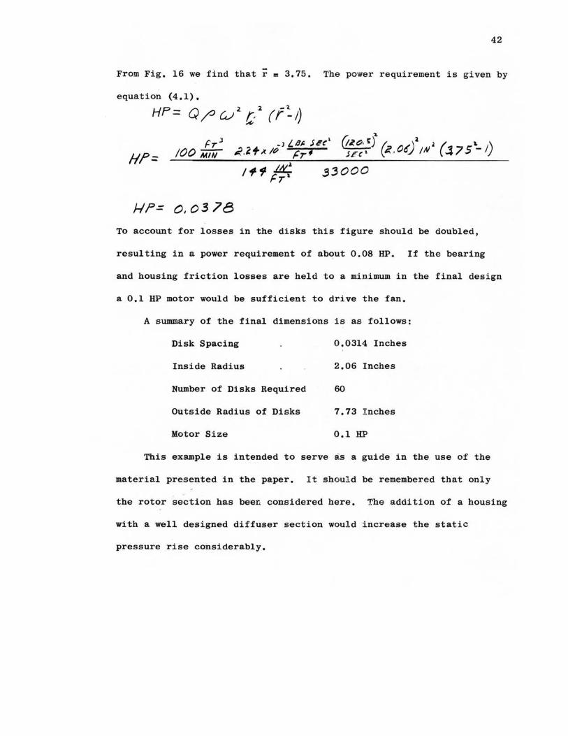
-From Fig. 16 we find that r = 3.75. The power requirement is given by
equation (4.1).
HP= Q /J CJ i C, 2 ( r:. I)
H?= 33000
/-I?= 0, 03 78 To account for losses in the disks this figure should be doubled,
resulting in a power requirement of about 0.08 HP. If the bearing
and housing friction losses are held to a minimum in the final design
a 0.1 HP motor would be sufficient to drive the fan.
A summary of the final dimensions is as follows:
Disk Spacing 0.0314 Inches
Inside Radius 2.06 Inches
Number of Disks Required 60
Outside Radius of Disks 7.73 I nches
Motor Size 0.1 HP
This example is intended to serve as a guide in the use of the
material presented in the paper. I t shoul d be remembered that onl y
the rotor section has been considered here-. The addition of a housing
with a well designed diffuser section woul d i ncrease t he stat i c
pressure rise considerably.

CHAPl'ER VI
CONCLUSIONS
The analytical and experimental investigations have supplied
information from which a friction disk rotor can be designed. The
experimental results agreed reasonably well with the mathematical
analysis and also indicated the magnitude of efficiency which can
be expected from a practical design. There are several factors
which limited the performance and efficiency of the test fan. The
main limiting factors were the presence of the shaft and disk spokes
in the inlet region, the spacers at the disk outlet and the lack of
a positive seal between the housing and the disks. Most of these
points could be eliminated or improved by redesigning the unit.
Other investigations (s], (6] have indicated that the obstructions i n
the inlet region may have a considerable effect on the efficiency. The
rotor designs in these references used throughbolts and spacers near
the outer edge of the disks. In this manner the entire inlet circle
was made available for the inlet port. Also the use of a cone shape
increases the strength of the disks and reduces the angle through
which the fluid must be turned before entering the disk gaps.
This type of fan has several inherent advantages over other
types. There is no vibration problem caused by vanes passing by the
diffuser outlet, and there are no liftin~ surfaces which can lead to
flow separation. Both of these factors lead to undesirable noise
43

levels in ordi nary fans. Further, a friction disk fan could be
designed to handle fluids of unusual densities and viscosities.
44
Several other factors should be considered when selecting a
fan of this type. Experience with the experimental rotor indicates
that the initial cost may be relatively low and that elaborate tools
and machinery are not necessary for its construction. The optimum
disk spacing decreases with the square root of the speed, thus the
manufacturing tolerance on the distance between the disks will
limit the maximum speed of the fan. Also the maximum flow rate is
limited by the inlet velocity and the physical size of the unit.
Areas of further study should include the determination of the
effect of inlet velocity and physical size on the efficiency of the
fan. The efficiency of conventional fans increases somewhat as they
are made larger.
BIBLIOGRAPHY
1. Beans, Elroy w., Performance Characteristics of a Friction Disk Turbine. Ph.D. Pensylvania State University, 1961.
2. Breiter, M. c. and K. Pohlhausen. Laminar Flow Between Two Parallel Rotating Disks. Aeronautical Research Laboratories, Wright-Patterson AFB, Ohio. Report No. ARL 62-318, 1962.
3. de Kovats, A. anq G. Desmur. Pumps, Fans and Compressors. Blackie and Son, Ltd. Glasgow, 1958.
4. Engineering News. Vol. 66, No. 15. October 12, 1911.
5. Flow Measurement. Supplement to ASME Power Test Codes. Chapter 4 , Part 5. American Society of Mechanical Engineers, New York, 1959.
6. Basinger, s. H. and L. G. Kehrt. Investigation of a Shear-Force Pump. JOURNAL OF ENGINEERING FOR POWER, Series A, Transactions of"the A.s.M.E., Page 201. July, 1963.
7. Rice, Warren. An Analytical and Experimental Investigation of Multiple Disk Pumps and Compressors. JOURNAL OF ENGINEERING FOR POWER, Series A, Transactions of the A.S.M.E., Page 191, July, 1963.
8. Scientific American, The. September 30, 1911.
9. Shigley, J.E. Machine Design. McGraw-Hill Book Co., Inc. New York, 1956
10. Technical World Magazi ne. Vol. 16. February, 1912.
11. Wallis, R. A. Axial Flow Fans. Academic Press, Inc. New York , 1961.
45
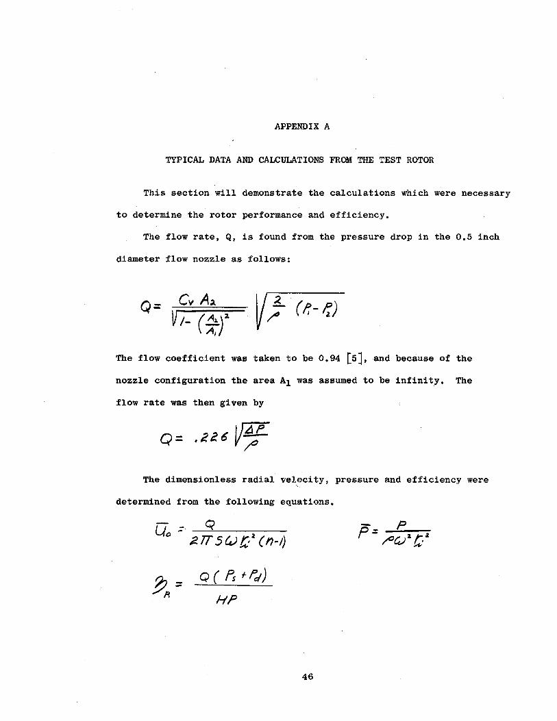
APPENDIX A
TYPICAL DATA AND CALCULATIONS FROM THE TEST ROTOR
This section will demonstrate the calculations which were necessary
to determine the rotor performance and efficiency.
The flow rate, Q, is found from the pressure drop in the 0.5 inch
diameter flow nozzle as follows:
Q= Cv A.a V,- (~)~
The flow coefficient was taken to be 0.94 [s], and because of the
nozzle configuration the area A1 was assumed to be infin:i.t_y. The
flow rate was then given by
o= .2uV~ The dimensionless radial velocity, pressure and efficiency were
-,.
determined from the following equations.
u = ___,_Q __ _ 0 ~lT S~t/ (n-1)
~= A
Q( f's ft;/)
HP
46
- p P = ~--41-a-,-.~a

DISK SIZE 5.2" X 1.7"
NO. OF DISKS 6
SPACING 0.025"
SPEED 2000 RPM
POWER REQUIREMENT
FLOW AP AMPS. VOLTS
.161 .408 2.90
.150 .403 '2.92
.119 .392 2.92
.089 .392 2.82
.069 .367 2.80
.036 .346 2.70 0 .305 2.52
FLOW Ps AP IN.- H20
.139 .115
.115 .135
.083 .155
.037 .205
. 0 .300
TABLE I
DISK FAN DATA
DATE 2-8-64
BAROMETER 29.02 In. Hg.
0 TEMP. · 75 F.
PERFORMANCE TEST
FLOW Ps AP IN.- H20
.166 .10
.150 .11
.130 .12
.095 .15
.070 .165
.039 .20 0 .302
TOTAL PRESSURE
P,1 IN. - H?.0 Disk 1 2 3 4 5
.145 .185 .200 .200 .160
.140 .180 .200- .200 .150
.140 .170 .195 .185 .150
.135 .160 .170 . 170 .140
.110 .120 .120 .115 .120
47

48
It was necessary to run three separate tests to obtain the proper
data, These tests are shown in the sampl~ data shcilet, Tabie I. The
tests determined the power requirements, the rotor performance and the
total pressure rise. The latter test was necessary to determine the
efficiency and it was also used to draw Fig. 14 in the text.
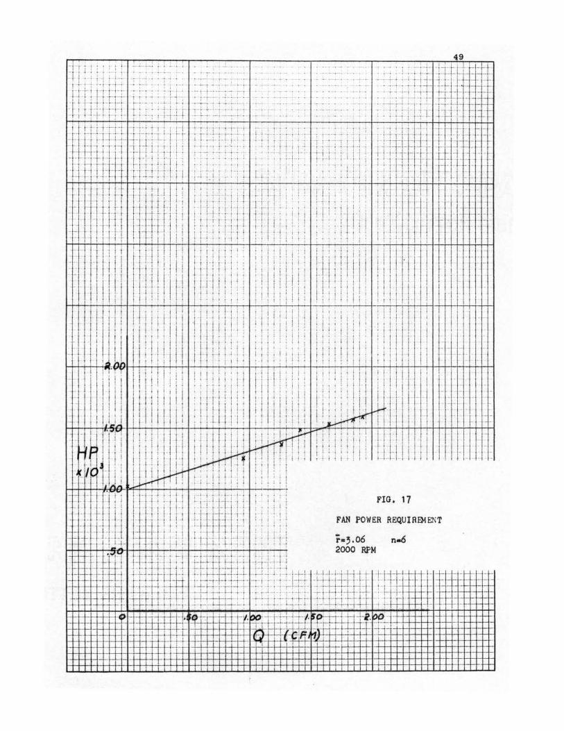
The power requirement was determined from the test data by plot-
ting power versus flow rate. This is shown in Table II and Fig. 17.
TABLE II
FAN POWER REQUIREMENT
FLOW CFM HP x 103
1.92 1.590 1.85 1.575 1.65 1.535 1.42 1~480 1.26 1.375 0.95 1-.250
0 1.030
From Fig. 17 it is apparent that the friction losses in the
system amounted to exactly 1.0 x 10⁻³ HP for this test. The ~ower
required by the rotor is found by subtracting this amount from the
curve shown.
The performance curve can be drawn by calculating P and U0
from the data in Table I. This is shown in Table III.
The rotor efficiency is determined from the sum of the average
dynamic pressure !!lld the static pressure as shown in Table IV.
~9
I - j I I I ' , , , . , , . 1 I . , . , . ! , 1 . '..1. I ____ · -_-_- ·_ -_· I , _ 1 _ 1: .. ' _ --__ . ·- I!' -- --11 , I ;
1 • ;11; · - i 1-r--1ri , ii i· , · 1 i1!1 - -_
.. ·.·_ :.· - _.-_ .. __ J, _ :1
_· -: t_ 1,_ -l,--',-__ 1 ·=·1··· 11·-.- l,_·_· !, :11 ! ! 1-1-iTI l i r ·J--r-1=1 ! ! '. ' . !- -~ i_ : ·: I ! I 1-1-· _··. ·-_ ~-f ·_ . I -_-+_-·
i ·1H-H·1-1l{-=':i, ij 11 11 -11-j'i = _-·_--_-- -,-~ ·.- ! -_----~-- I 11 1-1-i· rr:2 ·_· ,_ i I !; I' '' 'l ·- i I ,,- !·_-··. l - i ·1 : ; i !- I ! 1-1 I I ! i . ' . I ' '. = · j I I .. , i I I I 1 : : I 1 · I , i ! ; I i , 1 i i ' l '. i . • I t 1
--- I I ! 1 1 1 111 1 lllijjl! :ii !i : I '11-!i t-ii 1 1 j -- I - ~- <· -1 f = 11 '1 1 ! --,~ i -r1 '1, '1 ! -l, JI ·f!1 r ' I : : : : ! I l i 1~-'1 ! IT ! I , -- I I '1 - i _..
I , , ,- , , i · ! , ; , , • I· '· I j , , . 1 j 1
- .
.. 11 :I J :1 ,; ! 1, 1 ,:ili' ll, !! Ii li lli! I!: !i . I .
·I 1_, ! 11 i_J 1 I :I ii 1 1 l! _ii ! I i !· 1 1 i II ! I I i 11 i i ; j ; ! : i ! I I ! I j i,' 11 I, I : ·, I ·. 11 ! i, : ! ! I ! : I i I i : ! I i ! i - I ; 'I I I I
i 11 , 1,, ! · I i, I I 1- I I j i i i i i i I : . : I i !1 I ;I ·, 111 i : !Ii I ~- :. = - . I I 'I I 1j Ht I I I I I 1 I I : Ii! I'
i-...+-+-1-1-11-~:-~ 11 : ! ·,, : ! i I I II '. : : I ! ', : : ! 1' : : l ' : : ; ; i i ; ; I : I i i I -- I I 11· I I ' 1, ! ! I_, : ! I I I I I I '1 I : I ·, : ', ' . i i I I I I
: I ..!I I 1, ii 1, ; !, ! !ill! I 1, i i ii I I i i I ! I i ! i l UtLil I ... ·. :: : :: :. 111.UJ I I ! I i l I H·l I l I l I I ! : ! ! '~: : I 11-1
·~ ,~ r~ ;11ITTt11 1 HllmrrHtHftmrT
1i!:1!:111111 1.U11 1
·r_/~~ -,iji'.I 1 -· 1· , !.i.." I ii l r ;; f" I"' ~ 1.11 !··• 1 T !''lj I t t ,· I : . · 1 1- . , : : ! , : :
IJ ' - !__ i,..,,, I : ' I j ! I ~ L
,_ .... _1-~- j f i-l 11- -- ··11-l !.fl-' ci-l~ln-·J1i.j-j - 1 : I I_ ; !
: _ 14_-ij!_i 1: r :-1- 1 I 1,-: _jJf:-3::.:- = 1~1 : : i : 1
I ~ I I j I . 1-f·- - - - 1-· · . . . ' ' - 1-- __ !__ ·=-1- - - - , • - j I I
I ! 1 l J _,_ - - I ' I I ·- ... - 1- 1 -1 . ' I i -
, : ,_- _:_ -- . ~ -· - 1- -- , 1: l · ·,-1-·-!-- , 1+: l, i I I- r-~.06 n-6 ,- - - -· -! 1 + I·- - - -l I I l- - 1 .--, - ' +-'-· 1- ' ., . . : • 2000 RP. M 1 - - I , • 1 , , I t
FIG. 17
FAN POWER REQUIRE).IENT
l
i

50
TABLE IU
ROTOR PERFORMANCE
FLOW l's
CFM ~o IN.- H20 p
1.95 .471 .10 1~05 1.85 .447 .11 1.16 1.72 .415 .12 1.265 1.47 .355 .• 15 1.58 . 1.265 .306 .165 1.74 · o.942 .228 .20 2.11
0 0 .302 3.18
TABLE XV
ROTOR EFFICIENCY
PS pd (Avg.) AVG. FLOW TOTAL
~R CFM IN.- H20 IN.- H20· PRESSURE HP X 103
1.78 .115 .178 .293 .560 14.6 1.62 .135 .174 .309 .500 15.8 1.38 .155 .168 .323 .430 16~3
.92 .205 .155 .360 .280 18.6

APP~NDIX B
CALCULATION OF EFFECT OF VELOCITY CHANGES
IN THE INLET REGION ON THE PRESSURE MEASUREMENTS
The mathematical analysis is concerned with the pressure at
station (2), Fig. 18. It is desirable therefore to calculate the
magnitude of the error introduced by measuring this pressure at
station (1). When the fluid enters the disk section (station 2)
it has both radial and tangential components of velocity. The
velocity here is not the same as that at station (1).
Bernoulli's equation applied to this system shows that
.,.. .e [ l( + V.2] i!. l. 2.
(B-1)
The mathematical analysis assumed an initial radial velocity of
The axial inlet velocity \,I, can be expressed by
vi, = --2_ :: 4-TT d t;/ CJ Uo ( n-1) !Tl:-2 .... 1Tt/
Thus,
'w, = 4 cl c:J u() (n-1)
51
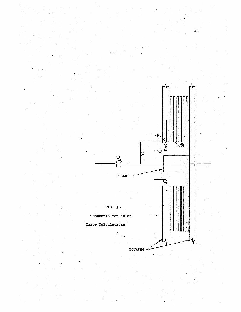
(µ t• ·,:.C.
S2
P. I
-c~--· --·--·-~~-SHA.Fl'
FIG. 18
Sohematic for Inlet
· Error Calculations
HOUSING
53
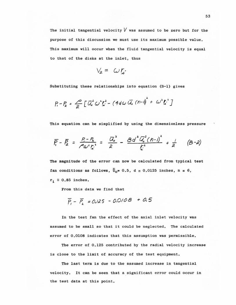
The initial tangential velocity V was assumed to be zero but for the
purpose of this discussion we must use its maximum possible value.
This maximum will occur when the fluid tangential velocity is equal
to that of the disks at the inlet, thus
Substituting these relationships into equation (B-1) gives
2. P,-1; = f-[u/ci .. t,2 - (1dwU(J (n- 1~ r i.l!-1.)
This equation can be simplified by using the dimensionless pressure
= 2 -.2 2
8d Lio ( n-1) r.2. ~
+ I ;:.
The magnitude of the error can now be calculated from typical test
fan conditions as follows, U0 = 0.5, d = 0.0125 inches, n = 6,
ri = 0.85 inches.
From this data we find that
P,- f, =O.ll5 -0.0108 + 0.5
In the test fan the effect of the axial i nlet velocity was
assumed to be small so that it could be negl ected. The calculated
error of 0.0108 indicates that this assumption was permissible.
The error of 0.125 contributed by t he radial velocity increase
is close to the limit of accuracy of the t e st equipment.
The last term is due to the assumed increase i n tangential
velocity. It can be seen that a significant e rror could occur in
the test data at this point.

VITA
Dixon Keith Foss
Candidate for the Degree of
Master of Science
Thesis: DESIGN ANALYSIS OF A FRICTION DISK ROTOR
Major Field: Mechanical Engineering
Biographical:
Personal Data: Born in Long Beach, California, February 7, 1941, the son of Edwin and Lorene Foss.
Education: Graduated from Edison High School Tulsa, Oklahoma, in 1958 and the following September entered Rose Polytechnic Institute; transferred to Oklahoma State University in January, 1960, and received Bachelor of Science degree in Mechanical Engineering in 1962; completed requirements for Master of Science degree in August, 1964.
Professional experience: Employed by National Science Foundation Plasma Research Facility; served on this project as undergraduate and graduate assistant for two years.