design & analysis of composite material drive shaft in
TRANSCRIPT

© 2018 JETIR July 2018, Volume 5, Issue 7 www.jetir.org (ISSN-2349-5162)
JETIR1807982 Journal of Emerging Technologies and Innovative Research (JETIR) www.jetir.org 583
DESIGN & ANALYSIS OF COMPOSITE
MATERIAL DRIVE SHAFT IN AUTOMOBILE
Sarvesh Kumar Verma1, L. P. Singh2
PG Scholar of Master of Technology1, Assistant Professor2
Department of Mechanical Engineering
Sam Higginbottom University of Agriculture, Technology and Sciences,
Allahabad-211007, Uttar Pradesh, India
ABSTRACT
This paper presents the characteristic details of propeller shaft to substitute its material with composite
material and suitability of material is analyzed by evaluating and comparing stress distribution & deformation
with in the shaft to replace the steel drive shaft with a piece of E-glass/ epoxy and E-carbon/epoxy with the
help of material properties. The 3D modeling and assembly of Drive shaft was done using SOLIDWORKS
software. Analysis is performed by using commercial FEA software ANSYS by considering static structural,
Rigid dynamics and modal analysis to estimate deformation, stress under given loads and frequencies. The
main objective of this paper is deduction of weight of an automobile transmission. Thus, in this project work
the propeller shaft of a vehicle was chosen and analyzed by replacing it with different materials.
Keywords — Drive shaft, transmission, ANSYS, Structural Steel, rigid dynamics, frequencies.
1. INTRODUCTION
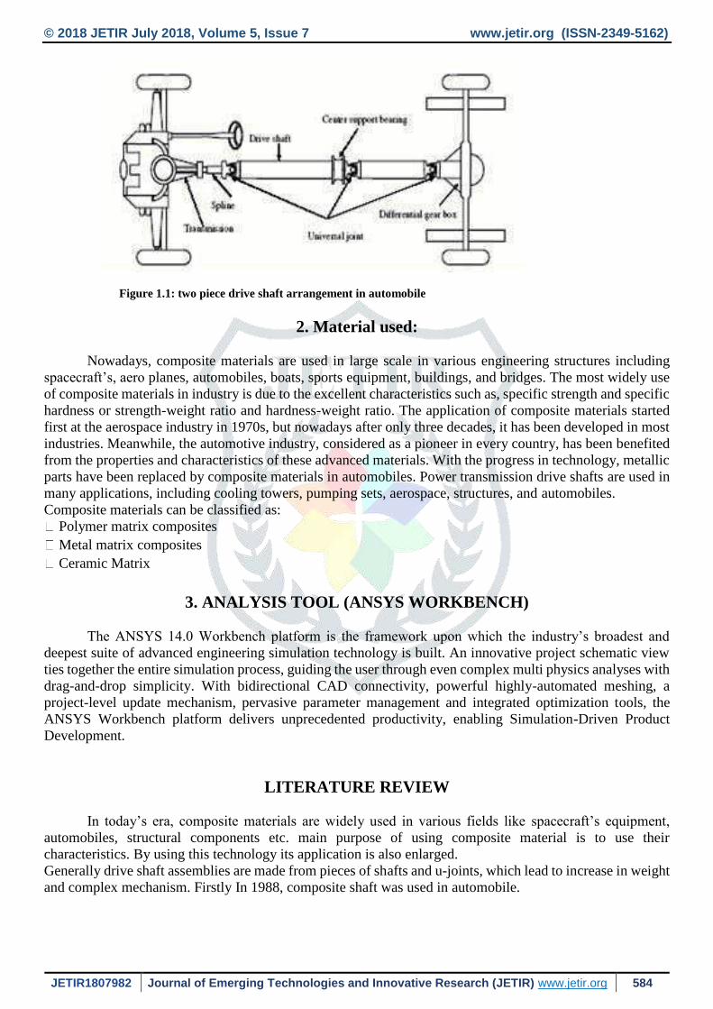
An automotive drive shaft transmits power from the engine to the differential gear of a rear wheel
drive vehicle. The drive shaft is usually manufactured in two pieces to increase the fundamental bending
natural frequency because the bending natural frequency of a shaft is inversely proportional to the square of
beam length and proportional to the square root of specific modulus which increases the total weight of an
automotive vehicle and decreases fuel efficiency. So, a single piece drive shaft is preferred here and the
material of it is considered to be Titanium alloy because of its high strength and low density. Drive shafts are
carriers of torque and are subject to torsion and shear stress, equivalent to the difference between the input
torque and the load. They must therefore be strong enough to bear the stress, whilst avoiding too much
additional weight as that would in turn increase their inertia.
In large rear wheel drive automobile, drive shaft is manufacturing in two pieces. This two pieces drive
shaft assembled and results in heavy assembled. The main agenda for two piece assembly is to increase its
natural frequency. Nowadays, energy conservation is most important objective in the design of automobile
and the effective measure is to reduce the weight of automobile.
Actually, there is direct relation between vehicle’s weight and fuel consumption. Use of composite
drive shaft leads to reduction in weight, also it is electrically non-conductive, long fatigue life. Composites
have a lower modulus of elasticity, because of that it works as shock absorber when torque peaks are
happened.
© 2018 JETIR July 2018, Volume 5, Issue 7 www.jetir.org (ISSN-2349-5162)
JETIR1807982 Journal of Emerging Technologies and Innovative Research (JETIR) www.jetir.org 584
Figure 1.1: two piece drive shaft arrangement in automobile
2. Material used:
Nowadays, composite materials are used in large scale in various engineering structures including
spacecraft’s, aero planes, automobiles, boats, sports equipment, buildings, and bridges. The most widely use
of composite materials in industry is due to the excellent characteristics such as, specific strength and specific
hardness or strength-weight ratio and hardness-weight ratio. The application of composite materials started
first at the aerospace industry in 1970s, but nowadays after only three decades, it has been developed in most
industries. Meanwhile, the automotive industry, considered as a pioneer in every country, has been benefited
from the properties and characteristics of these advanced materials. With the progress in technology, metallic
parts have been replaced by composite materials in automobiles. Power transmission drive shafts are used in
many applications, including cooling towers, pumping sets, aerospace, structures, and automobiles.
Composite materials can be classified as:
Polymer matrix composites
Metal matrix composites
Ceramic Matrix
3. ANALYSIS TOOL (ANSYS WORKBENCH)
The ANSYS 14.0 Workbench platform is the framework upon which the industry’s broadest and
deepest suite of advanced engineering simulation technology is built. An innovative project schematic view
ties together the entire simulation process, guiding the user through even complex multi physics analyses with
drag-and-drop simplicity. With bidirectional CAD connectivity, powerful highly-automated meshing, a
project-level update mechanism, pervasive parameter management and integrated optimization tools, the
ANSYS Workbench platform delivers unprecedented productivity, enabling Simulation-Driven Product
Development.
LITERATURE REVIEW
In today’s era, composite materials are widely used in various fields like spacecraft’s equipment,
automobiles, structural components etc. main purpose of using composite material is to use their
characteristics. By using this technology its application is also enlarged.
Generally drive shaft assemblies are made from pieces of shafts and u-joints, which lead to increase in weight
and complex mechanism. Firstly In 1988, composite shaft was used in automobile.

© 2018 JETIR July 2018, Volume 5, Issue 7 www.jetir.org (ISSN-2349-5162)
JETIR1807982 Journal of Emerging Technologies and Innovative Research (JETIR) www.jetir.org 585
Shaw D, Simitses DJ, Sheinman (1985) investigated about Imperfection sensitivity of laminated cylindrical
shells in torsion and axial compression. They found that the linear analysis is considered satisfactory in
comparison with nonlinear analysis due to the fact that cylindrical shells under torsion are less sensitive to
imperfections.
Bhirud Pankaj Prakash, Bimlesh Kumar Sinha (2000) evaluated that by substituting composite structures
for conventional metallic structures has many advantages because of higher specific stiffness and strength of
composite materials. In the recent days, there is a huge demand for a light weight material such as fiber
reinforced polymer composites seems to be a promising solution to this arising demand. These materials have
gained attention due to their applications in the field of automotive, aerospace, sports goods, medicines and
household appliances. The overall objective of this work is to analyze a composite drive shaft for power
transmission. Substituting composite structures for conventional metallic structures has many advantages
because of higher specific stiffness and strength of composite materials. This work deals with the replacement
of conventional steel drive shafts with a Kevlar/epoxy or E glass polythene resin composite drive shaft for an
automotive application. The intention of work is to minimize the weight of drive shaft. In this present work
an attempt has been to estimate the deflection, stresses, and natural frequencies under subjected loads using
FEA (Ansys). Further comparison carried out for both loads using FEA. Further comparison carried out for
both optimized and stress intensity factor found for both Steel and composite drive shafts.
Parshuram D, Sunil Mangsetty (2013) the main concept of our project is to reduce the weight of automotive
drive shaft with the utilization of composite material. Composite materials have been used in automotive
components because of their properties such as low weight, high specific stiffness, corrosion free, ability to
produce complex shapes, high specific strength and high impact energy absorption etc. As the automotive
drive shaft is a very important component of vehicle. The modeling of the drive shaft assembly was done
using CATIA software. A shaft has to be designed to meet the stringent design requirements for automotive.
In automobiles the drive shaft is used for the transmission of motion from the engine to the differential. An
automotive propeller shaft, or drive shaft, transmits power from the engine to differential gears of rear wheel-
driving vehicle. In present work an attempt has been to estimate deflection, stresses under subjected loads &
natural frequencies using FEA.
Bhushan K. Suryawanshi, Prajitsen G. Damle, (2013) developed a new manufacturing method, in which a
carbon fiber epoxy composite layer was co-cured on the inner surface of an aluminum tube rather than
wrapping on the outer surface to prevent the composite layer from being damaged by external impact and
absorption of moisture. Replacing composite structures with conventional metallic structures has many
advantages because of higher specific stiffness and higher specific strength of composite materials. By
considering the thermal residual stresses of the interface between the aluminum tube and the composite layer,
the optimum stacking sequence is calculated with the help of finite element analysis. Press fitting method for
the joining of the aluminum/composite tube and steel yokes was devised to improve reliability and to reduce
manufacturing cost, compared to other joining methods such as adhesively bonded, bolted or riveted and
welded joints. The joining of the aluminum - composite tube and steel yoke with improved reliability and
optimum manufacturing cost is done by press fitting. In order to increase the torque transmission capacity
protrusion shape is provided on the inner surface of steel yoke which will fit on Universal joints.
Harshal Bankar, Viraj Shinde, P. Baskar (2013) proved the use of composite material in reducing the
weight of shaft significantly as the composite has lower density in their work. The initial torque required to
give rotation to the transmission system is large, as the weight reduces this surplus torque is utilized to propel
the vehicle, at the same time inertial effect of rotating part decreases. Also the reduction in the weight of shaft
increases the 1st modal frequency of bending; hence this shaft can be utilized for higher frequencies than
steel. The reduction in weight gives further advantage in the increase in fuel economy of vehicle. The stress
distribution and the maximum deformation in the shaft are the functions of the stacking of material. The
optimum stacking of material layers can be used as the effective tool to reduce weight and stress acting on the

© 2018 JETIR July 2018, Volume 5, Issue 7 www.jetir.org (ISSN-2349-5162)
JETIR1807982 Journal of Emerging Technologies and Innovative Research (JETIR) www.jetir.org 586
drive shaft. The design of drive shaft is critical as it is subjected to combined loads. The designer has two
options for designing the drive shaft whether to select solid or hollow shaft. The solid shaft gives a maximum
value of torque transmission but at same time due to increase in weight of shaft the 1st mode frequency
decreases. Also shaft outer surface facing most of the stress coming on to it and the inner material layer
experienced less stress, hence the inner layers increasing the weight of shaft and not utilized for stress
distribution properly, that’s why the hollow drive shaft is best option.
P. Jayanaidu, M. Hibbatullah, Prof. P. Baskar (2013) present the concept to deals with optimization of
drive shaft using the ANSYS. Substitution of Titanium drive shafts over the conventional steel material for
drive shaft has increasing the advantages of design due to its high specific stiffness, strength and low weight.
Drive shaft is the main component of an automobile. It is used to transfer the motion from the engine to the
wheel. Drive shaft is the assembly of many small components. Use of conventional steel for manufacturing
of drive shaft has many disadvantages such as low specific stiffness and strength. Many methods are available
at present for the design optimization of structural systems. This paper discusses the past work done on drive
shafts using ANSYS and design and modal analysis of shafts made of Titanium alloy (Ti-6Al-7Nb).
M.R. Khoshravan, A. Paykani (2014) presents a design method and a vibration analysis of a carbon/epoxy
composite driveshaft. The design of the composite drive shaft is divided into two main sections: First, the
design of the composite shaft and second, the design of its coupling. Some parameters such as critical speed,
static torque, fiber orientation and adhesive joints were studied. Tsai-Hill failure criterion was implemented
to control the rupture resistance of the composite shaft and then its critical speed analysis and modal analysis
were carried out using ANSYS. The behavior of materials is considered nonlinear isotropic for adhesive,
linear isotropic for metal and orthotropic for composite shaft. The results showed significant points about the
appropriate design of composite drive shafts. The substitution of composite drive shaft has resulted in
considerable weight reduction about 72% compared to conventional steel shaft. Furthermore, results revealed
that the orientation of fibers had great influence on the dynamic characteristics of the composite shaft.
4. METHODOLOGY
It deals with the analysis of drive shaft which is obtained by the following methods-
4.1. Mathematical analysis
In the mathematical analysis all the factors such as maximum deflection, maximum Von- misses stress,
maximum shear stress etc. In it all the calculation done by manually. The fundamental natural bending
frequency for passenger cars, small trucks, and vans of the propeller shaft should be higher than 6,500 rpm to
avoid whirling vibration and the torque transmission capability of the Propeller shaft should be larger than
350 Nm. The Propeller shaft outer diameter should not exceed 100 mm due to space limitations.
Properties (mechanical) of Steel Shaft
Poisson’s ratio = 0.27
Shear modulus = 82 Mpa
Tensile yield strength = 325 Mpa
Tensile ultimate strength = 385 Mpa

© 2018 JETIR July 2018, Volume 5, Issue 7 www.jetir.org (ISSN-2349-5162)
JETIR1807982 Journal of Emerging Technologies and Innovative Research (JETIR) www.jetir.org 587
R = 0.108 m; L = 1.48 m; E = 207e9 pa Density = 7870 kgm3
Where,
R = Radius of shaft
L = Length of the shaft
E = Young’s Modulus of Kevlar
T = Applied Torque
Engine Torque Calculation
Rotational speed = 2600 rpm Maxm Power = 110 HP i.e. 82.03 KW
The torque transmission capacity of shaft is calculated by using torsional equation
Torque T = P/2πn
= (82.03KW) (1000W/KW)/2π (2600rev/min)/ (60sec/min)
= 301.28 Nm
Maxm Force = Torque/Length
= 301.28/1.48
= 203.568 N
Deflection = Y Max
= 1.492*10-5 m
I = π/64(d04 - di
4) ……………………………….. (1)
For hollow shaft, polar moment of inertia,

© 2018 JETIR July 2018, Volume 5, Issue 7 www.jetir.org (ISSN-2349-5162)
JETIR1807982 Journal of Emerging Technologies and Innovative Research (JETIR) www.jetir.org 588
Where
J = polar moment of inertia,
𝜏𝑠 = torsional shear stress, r = d/2 where d is the diameter of shaft
Maximum Shear Stress: Ʈ
= 2.436*106 Pa
Maximum Von-Misses Stress:
= 301721.6072
= 3.012*105 Pa
Also mass is calculate of shaft for both material
Area = π/4(d2)
A = 0.03665 m2
Volume of shaft V= 0.03665*1.48 = 0.05424 m3
Mass of shaft, m = σ*V= 7850*0.05424
= 425.78 kg
Properties (mechanical) of Composite Shaft
Now for composite material maximum shear stress is calculated
Density of Kevlar shaft σ = 1470 kgm3
Young Modulus of Kevlar E = 990 Pa
Length L = 1.48 m

© 2018 JETIR July 2018, Volume 5, Issue 7 www.jetir.org (ISSN-2349-5162)
JETIR1807982 Journal of Emerging Technologies and Innovative Research (JETIR) www.jetir.org 589
Area = π/4(d2)
A = 0.03665 m2
Volume of shaft V= 0.03665*1.48 = 0.05424 m3
Mass of shaft, m = σ*V= 1470*0.05424
= 79.73 kg
After analytical calculation analysis is carried out using ANSYS
Now ANSYS analysis is being carried out for the composite material shaft
4.2. Design Analysis
The finite element method is a powerful numerical tool widely used to solve nonlinear problems of
elasticity, solids and structures. In this project, modeling was performed using the commercial code ANSYS.
The finite element modeling’s based on a 3D element. The ANSYS14.0 Workbench platform is the framework
upon which the industry’s broadest and deepest suite of advanced engineering simulation technology is built.
An innovative project schematic view ties together the entire simulation process, guiding the user through
even complex multi physics analyses with drag-and-drop simplicity. With bidirectional CAD connectivity,
powerful highly-automated meshing, a project-level update mechanism, pervasive parameter management
and integrated optimization tools, the ANSYS Workbench platform delivers unprecedented productivity,
enabling Simulation-Driven Product Development.
In this study, a FEA was conducted by using ANSYS commercial software. The 3D model was
developed and a typical meshing was generated. The drive shaft was fixed at both ends and it was subjected
to torque in the middle. The torque transmission capability of the drive shaft was taken as 350 Nm, the length
and the outer diameter here were considered as 2 meters and 120 millimeters respectively. The shaft rotates
at a constant speed about its longitudinal axis. The shaft has a uniform, circular cross-section. The shaft was
perfectly balanced, all damping and non-linear effects were excluded. The stress strain relationship for
composite material is linear and elastic; hence Hook’s law is applicable for composite material. Since lamina
is thin and no out-of-plane loads were applied, it was considered as under the plane stress. Since the fiber
volume of 60% is the standard fiber volume fraction for most industries, it was selected for composite drive
shaft.
In the following analysis Kevlar and steel shafts were compared with each other in terms of their
deformation, maximum Shear stress and Von-Misses stress under same conditions as in the previous journal.
The Maximum stress undergone and the total deformation occur in Steel under the given conditions. Kevlar
is better in terms of maximum stress and deformation as these parameters produced in this shaft are less when
compared to steel.
Process of Structural Analysis
MODELING OF PROPELLER SHAFT IN SOLID WORKS:
In this work propeller shaft is selected for structural analysis using ANSYS. The various materials
using finite element analysis software ANSYS 14.0.

© 2018 JETIR July 2018, Volume 5, Issue 7 www.jetir.org (ISSN-2349-5162)
JETIR1807982 Journal of Emerging Technologies and Innovative Research (JETIR) www.jetir.org 590
The propeller shaft is designed by required dimensions into the modeling software SOLIDWORKS. The
geometry of the propeller shaft is designed in SOLIDWORKS is imported to the analysis software in the IGES
format. The designed propeller shaft is below
Propeller Shaft Model and Mesh
The modeling of propeller shaft using SOLIDWORKS and the same is used for structural analysis. In
this work node elements selected for meshing. The finite element mesh of the piston model used in ANSYS
is shown Figure.
Fig: 4.1. Model of Shaft Messing
5. Result and Discussion
5.1. Structural Analysis with different Material
Finite element analysis is a computer based analysis technique for calculating the strength and behavior of
structures. In the FEM the structure is represented as finite elements. These elements are joined at particular points
which are called as nodes. The FEA is used to calculate the deflection, stresses, strains temperature, buckling behavior
of the member. In our project FEA is carried out by using the ANSYS 14.0. Initially we don’t know the displacement
and other quantities like strains, stresses which are then calculated from nodal displacement. A static analysis is used to
determine the displacement, strain, von misses stress and force in structure or compounds caused by load that do not
significant inertia and damping effects. The static analysis of drive shaft is done by ANSYS software 14.0.
Kevlar/Epoxy and Glass/Epoxy are having more deformation under tensile and flexure load hence it
replaces the two pieces of steel drive shaft into single shaft with better transmission of power. Because of
their elasticity, they decrease the stress and act as a best shock absorber when the torque is more. Also
Kevlar/Epoxy and Glass/Epoxy having less deformation under impact load so that it can absorb more energy
because of its toughness.
The difference between the structural steel and composite (Kevlar) material are as given below with the
different conditions.
© 2018 JETIR July 2018, Volume 5, Issue 7 www.jetir.org (ISSN-2349-5162)
JETIR1807982 Journal of Emerging Technologies and Innovative Research (JETIR) www.jetir.org 591
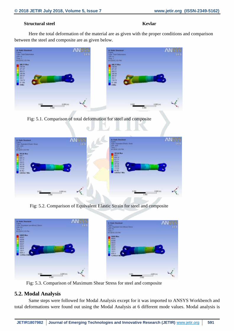
Structural steel Kevlar
Here the total deformation of the material are as given with the proper conditions and comparison
between the steel and composite are as given below.
Fig: 5.1. Comparison of total deformation for steel and composite
Fig: 5.2. Comparison of Equivalent Elastic Strain for steel and composite
Fig: 5.3. Comparison of Maximum Shear Stress for steel and composite
5.2. Modal Analysis
Same steps were followed for Modal Analysis except for it was imported to ANSYS Workbench and
total deformations were found out using the Modal Analysis at 6 different mode values. Modal analysis is

© 2018 JETIR July 2018, Volume 5, Issue 7 www.jetir.org (ISSN-2349-5162)
JETIR1807982 Journal of Emerging Technologies and Innovative Research (JETIR) www.jetir.org 592
used to determine the vibration characteristics such as natural frequencies and mode shapes of a structure or
a machine component while it is being designed. It can also be a starting point for another more detailed
analysis such as a transient dynamic analysis, a harmonic response analysis or a spectrum analysis. Modal
analysis is used to determine the natural frequencies and mode shapes of a structure or a machine component.
Fig: 5.4. Comparison of first set of natural frequency analysis for steel and composite
Fig: 5.5. Comparison of second set of natural frequency analysis for steel and composite
Fig: 5.6. Comparison of third set of natural frequency analysis for steel and composite

© 2018 JETIR July 2018, Volume 5, Issue 7 www.jetir.org (ISSN-2349-5162)
JETIR1807982 Journal of Emerging Technologies and Innovative Research (JETIR) www.jetir.org 593
Fig: 5.7. Comparison of fourth set of natural frequency analysis for steel and composite
Fig: 5.8. Comparison of fifth set of natural frequency analysis for steel and composite
Fig: 5.9. Comparison of sixth set of natural frequency analysis for steel and composite
Model (A4) > Modal (A5) > Solution (A6) > Frequency

© 2018 JETIR July 2018, Volume 5, Issue 7 www.jetir.org (ISSN-2349-5162)
JETIR1807982 Journal of Emerging Technologies and Innovative Research (JETIR) www.jetir.org 594
Fig: 5.10. Graph of Frequency variation
6. CONCLUSION
The E-Glass/ Epoxy, High Strength Carbon/Epoxy and High Modulus Carbon/Epoxy composite drive
shafts have been designed to replace the steel drive shaft of an automobile machine, which employs Propeller
shafts, in general. This was achieved by reducing the weight of the Propeller shaft with the use of different
composite materials. The Propeller shaft of a vehicle was chosen for determining the dimensions, which were
then used for creating a model in SOLIDWORKS. Being a complex assembly of a number of parts, it had to
be analyzed only for Propeller shaft in ANSYS 14.0. At the few materials were chosen for the comparative
analysis, including steel, which was used for reference. Taking into consideration the weight saving,
deformation, shear stress induced and resonant frequencies it is observed that composite material has the most
encouraging properties to act as the replacement for steel out of all the materials.
Table 6.1 Result of both materials
On the basis of stress calculation, report says that composite material shaft is advisable to replace
conventional material shaft.
1 2 3 4 5 6
2.86E-05 2.07E-04 4.24E-04
1.90E+01 20.829
126.45
FREQUENCY CHART
0
50
100
150
200
250
300
350
400
450
1 2 3
425.78350
79.872
Weight Chart

© 2018 JETIR July 2018, Volume 5, Issue 7 www.jetir.org (ISSN-2349-5162)
JETIR1807982 Journal of Emerging Technologies and Innovative Research (JETIR) www.jetir.org 595
Weight of shaft is reducing about 81% after using composite material.
The torque transmission capacity of the composite drive shafts has been calculated by neglecting and
considering the effect of centrifugal forces and it has been observed that centrifugal forces will reduce
the torque transmission capacity of the shaft.
The E-Glass/ Epoxy, High Strength Carbon/Epoxy and High Modulus Carbon/Epoxy composite drive
shafts have been designed to replace the steel drive shaft of an automobile.
The presented work also deals with design optimization i.e. converting two piece drive shaft
(Structural steel shaft) in to single piece light weighted composite drive shaft.
The drive shaft of the dimensions, which were used then used for the material properties of composites
were used the stability of drive shaft is ensured by limiting the include values within the permissible
range in ANSYS Workbench 14.0.
REFERENCES
1. M.R. Khoshravan, A. Paykani (2012) “Design of a Composite Drive Shaft and its Coupling for
Automotive Application” Journal of Applied Research and Technology vol.10, pp. 826-834.
2. Parshuram D & Sunil Mangsetty (2013) “Design and Analysis of Composite/Hybrid Drive Shaft for
Automotive” The International Journal of Engineering and Science ISSN: 2319 – 1813 ISBN: 2319–1805
Vol. 2 Issue 01 PP160-171.
3. Bhushan K. Suryawanshi, Prajitsen G. Damle (2013), Review of Design of Hybrid Aluminum/
Composite Drive Shaft for Automobile, International Journal of Innovative Technology and Exploring
Engineering (IJITEE), ISSN:2278-3075, Volume-2, Issue-4, 259-266.
4. Harshal Bankar, Viraj Shinde and P. Baskar (2013), Material optimization and weight reduction of
drive shaft using composite material, IOSR-JMCE, ISSN:2278-1684, Volume 10, Issue 1, PP 39-46.
5. P. Jayanaidu, M. Hibbatullah, Prof. P. Baskar(2013) “ Analysis of a Drive Shaft for Automobile
Applications” IOSR Journal of Mechanical and Civil Engineering (IOSR-JMCE), e-ISSN: 2278-1684,p-
ISSN: 2320-334X, Volume 10, PP 43-46
6. Bhirud Pankaj Prakash and Bimlesh Kumar Sinha (2014), ‘Analysis of Drive Shaft’, International
Journal of Mechanical and Production Engineering, Vol.-2, Issue-2, pp. 24-29.
7. Kalaiyarasan A and Sankareswaran N (2016) “Design and Analysis of Drive Shaft by different
Reinforcement material in metal Matrix Composite” International Journal of Recent Scientific Research,
ISSN: 0976-3031, Vol. 7, Issue, 8, pp. 12921-12924.