design, aerodynamics, and vision- based control of the … · design, aerodynamics, and...
TRANSCRIPT
Design, aerodynamics, and vision-based control of the DelFly
G.C.H.E. de Croon, K.M.E. de Clercq, R. Ruijsink, B. Remes, and C. deWagter
Aerospace Software and Technologies Institute, Technical University of Delft
Rotterdamseweg 380, 2629 HG, Delft, the Netherlands
[Received date; Accepted date] – to be inserted later
ABSTRACTLight-weight, autonomous ornithopters form a promise to observe places that are toosmall or too dangerous for humans to enter. In this article, we discuss the DelFly project,in which we follow a top-down approach to ever smaller and more autonomousornithopters. Top-down signifies that the project always focuses on complete flyingsystems equipped with camera. We give arguments for the approach by explaining whichfindings on the DelFly I and DelFly II recently led to the development of the DelFlyMicro: a 3.07-gram ornithopter carrying a camera and transmitter onboard. Thesefindings concern the design, aerodynamics, and vision-based control of the DelFly. Inaddition, we identify main obstacles on the road to fly-sized ornithopters.
1. INTRODUCTIONOne of the goals of research on Micro Air Vehicles (MAVs) is to arrive at fly-sized MAVs that can flyautonomously in complex environments. Such MAVs form a promise for observation tasks in placesthat are too small or too dangerous for humans to enter. Their small size would allow the MAVs to enterand navigate in narrow spaces, while autonomous flight would allow the MAV to operate at a largedistance from its user.
The requirements for the MAV described above are legion. For one, it needs to be as light as possiblefor endurance, while having enough onboard sensors and processing that allow it to navigateautonomously. Moreover, it needs to be able to hover, allowing it to get a “good look” at the object ofobservation. At the same time, it needs to fly at higher speeds to travel larger distances.
It may come as no surprise that in their quest for a fly-sized MAV, researchers draw inspiration fromnatural systems. For example, flying insects comply with the requirements mentioned above and canthus provide inspiration for solving the engineering problems encountered in the creation of a fly-sizedMAV. One of the key properties of systems inspired by flying insects is that they use flapping wingpropulsion (they are ornithopters)1,2,3,4,5,6,7,8,9. Especially at smaller sizes, this propulsion methodproduces more lift than fixed wing configurations10,11,12,13.
Essentially, there are two main approaches to creating small autonomous ornithopters: bottom-upand top-down. In the bottom-up approach, one starts by creating all the tiny parts that are deemedimportant to a fly-sized ornithopter2,14,15. The most remarkable example of this approach is the work ofthe Harvard Microrobotics Laboratory. They succeeded in creating a 60 mg robotic insect, which canproduce sufficient lift to take off vertically. To achieve this, they made use of Smart CompositeMicrostructures (SCM)2. The robotic insect was still fixed to taut guide wires that restricted the robotto vertical motion and provided both energy and control. In future work, the group plans to allow alldegrees of freedom and to incorporate onboard energy supply, sensors, and processing.
In the top-down approach, one starts with a fully functioning (relatively large-scale) ornithopter. Bystudying this ornithopter, theoretical insights can be gained into the complex of necessary properties fora smaller version. Research then progresses by creating and studying ever smaller systems, whilealways maintaining a fully functioning flying robot. One advantage of this approach is that it allowsinterplay between theory and practice. Especially in the field of artificial intelligence, having a physicaland fully functioning robot is of great value16,17,18: real-world tests force the experimenters to take intoaccount all aspects of the robotic system. In addition, they reveal physical properties of the system that
71
Volume 1 · Number 2 · 2009

can be exploited by the algorithms. In this article, we focus on the top-down approach followed in our DelFly project19. We give
arguments for our approach, and explain how findings on the (larger) DelFly I and DelFly II led to thecreation of the DelFly Micro, a 3.07-gram ornithopter carrying a camera and transmitter onboard (seeFigure 1). Carrying a camera is essential, since the project focuses on vision controlled ornithopters.
In the article we discuss the most important aspects of the DelFly ornithopters in turn. First, we giveinsight into the design choices of the DelFly (Section 2). Then, we study the aerodynamics of theDelFly, and explain how the results may improve its design (Section 3). Subsequently, we discuss theelectronics on the DelFly, and the corresponding problems that we had to solve (Section 4). We reporton our approach to reaching autonomous flight in (Section 5). Finally, we discuss the DelFly Micro andidentify the main challenges ahead to developing even smaller versions (Section 6).
Figure 1. DelFly I (50 cm span, 21.00g), DelFly II (28 cm span, 16.07g)and DelFly Micro (10 cm span, 3.07g).
2. DESIGN AND MATERIALSIn this section, we first motivate the general concept of the DelFly design: a biplane wing model(Subsection 2.1). Subsequently, we discuss the crank mechanism (Subsection 2.2), the wings(Subsection 2.3), the tail (Subsection 2.4), and the fuselage (Subsection 2.5). For all these parts, weexplain how and why they have evolved over time, as a result of measurements and flight experiences.
2.1 General Concept.The main aim of the DelFly design was to achieve an airborne camera platform with good flightcharacteristics. This ruled out drastic design revolutions compared to existing ornithopter designs. Forexample, (semi-) rigid wings articulated with many degrees of freedom were not considered. Such asystem is difficult to control, since there is a lack of knowledge both on how its movements should andcould be actuated in a sensible manner.
Consequently, three existing ornithopter concepts were studied for the creation of the DelFly I20. Thefirst concept was a simple monoplane with one set of wings. The second was a biplane concept wheretwo sets of wings were placed above each other. These wings moved in counter phase on a commonrotational axle. The third concept involved a tandem configuration, where two wings were placed onebehind the other. The wings of this concept also moved in counter phase. We wanted to test the threeconcepts with respect to the flight speed, the power consumption, and the stability of the ornithopter’sbody during flight. This last characteristic is vital for the ornithopter’s role as a camera platform.
To test the concepts, models were made of simple balsa wood and commonly available tissue. Themodels were powered by rubber bands. The models are well known in the indoor free flight modelworld and were acquired as standard kits21. All three models had the same span, chords, and weight. Asa consequence, the wing loading of the monoplane was two times as high as the others. Each modelwas flight tested, while measuring the flying distance, the flight time, and the number of winds of therubber band before and after the flight. The latter two quantities can be used to calculate the flapping
72 Design, aerodynamics, and vision-based control of the DelFly
International Journal of Micro Air Vehicles

frequency and the energy stored in the rubber band before and after the flight. Table 1 shows theaverage flight speed, power consumption, and rocking amplitude (periodic fuselage motionperpendicular to the flight path) for the three models.
Table 1: Test results on model planes used to define the DelFly concept 20.
Monoplane Biplane Tandem
Average flight speed 2.35 m/s 1.40 m/s 1.36 m/sPower consumption 0.75 W 0.69 W 1.00 WRocking amplitude ~80 mm ~0 mm ~0 mm
The table shows that the monoplane had the highest flight speed: a logical result of the high wingloading., For the given weight and size it consumed more power than the biplane model. Furtheranalysis indicated that a monoplane with the same total wing area as the biplane would consume lesspower. Yet, this would increase the size of the MAV, contrasting the emphasis on small MAV-dimensions. The lower power consumption for the same size led us to select the biplane model. Anadditional advantage of the biplane model is that the low rocking amplitude of the fuselage in flightmakes it a suitable camera platform.
2.2 Crank mechanism.DelFly I had a crank mechanism as the main wing axle, shown in the left part of Figure 2. Its gear axleswere placed in the flying direction. The advantage of this setup was that it yielded simple connectingrods with all movements in one plane. The disadvantage was that the phase between the two sets ofwings was not equal, which led to a rotational reaction movement on the fuselage and thus the camera.This resulted in blurred camera images.
To overcome this lack of symmetry, we designed a new drive mechanism with the gear axleperpendicular to the flying direction. This setup is shown in the right part of Figure 2. Used on theDelFly II, this mechanism has proven to give a good symmetrical movement with no rocking motionof the fuselage. The highest thrust (force along fuselage axis) is required during hover. It was achievedby maximizing the flapping amplitude (flap angle) and forced us to attach the connecting rod as closeto the fuselage as possible.
Figure 2. Schematics of the crank mechanism of DelFly I (left) 20 and DelFly II (right).
2.3 WingsThe design of the wings started with the standard model kits, a form that has been known for decades.The material consisted of 6 microns Mylar foil. A stroboscope box was constructed to visualize the
G.C.H.E. de Croon, K.M.E. de Clercq, R. Ruijsink, B. Remes, and C. de Wagter 73
Volume 1 · Number 2 · 2009

form of these wings during motion20. The time lapse study indicated that the flexibility of such wingswas too high. Inspection of the wing deformations showed that the trailing edge of the wing wascompletely folding while flapping. As such, it did not contribute efficiently to the generation of lift.Therefore, we introduced stiffeners into the wing of the DelFly I. Several concepts were tested and twostiffeners gave the best result.
After flying for an extended time with the DelFly I, the foil deteriorated and a higher flappingfrequency was needed for hovering. In addition, the parts of the wing surpassing the straight lines inbetween the stiffeners would curl up. This was an indication that these wing parts were still spurious,and they disappeared in the design of both the DelFly II (Figure 3) and DelFly Micro.
The shape of the wing is an important determining factor for the lift. Therefore, thorough studies onthe relation between wing shape and lift may contribute significantly to further minimization ofornithopters1,11. An example of such a study is 11. Interestingly, the shape of the DelFly wings is verysimilar to their wing type ‘A’, which produces a high lift at 0 wind velocity. Our own wing setup wasmore thoroughly tested in later phases with high speed camera visualization22, and recently withParticle Image Velocimetry (PIV) as described in Section 3.
2.4 TailThe DelFly I had a V-tail, because of its mechanical simplicity. An inverted V-tail was used in order togive a favorable yaw-roll coupling, making the turns without ailerons smoother.
Figure 3. Top view of the DelFly II with two stiffeners per half wing.
During the DelFly II development the inverse V-tail was abandoned for a conventional cross-tail.The reason behind that is the placement of the tail in the wake of the flapping wings during hover. Withthe original inverse V-tail the control of the longitudinal motion became rather marginal in thissituation.
In addition, the tail was placed closer to the wings. This improved the stability and control duringthe hover without reducing these aspects during cruise. The interaction of the horizontal tail with thevortices shedding from the wing might be playing a part, but this has not yet been studied.
The tail of some versions of the DelFly II is extended, such that the vehicle can take off and land asa tail sitter. During the testing of the concept a flight has been performed with 39 take-off and landingson a single battery charge, see 19.
2.5 Fuselage.The rear part of the fuselage is a light carbon tube. As all commercial tubes were found to be too heavy,a tube was constructed in-house. Basically it consists of a carbon sleeve that is impregnated with epoxy.When the nominal diameter of the woven carbon sleeve is small, the fibre orientation is stronglytangential which yields high torsion stability. When the nominal diameter is large, the orientation ismore longitudinal giving more bending stability. The latter is used on the fuselage.
74 Design, aerodynamics, and vision-based control of the DelFly
International Journal of Micro Air Vehicles
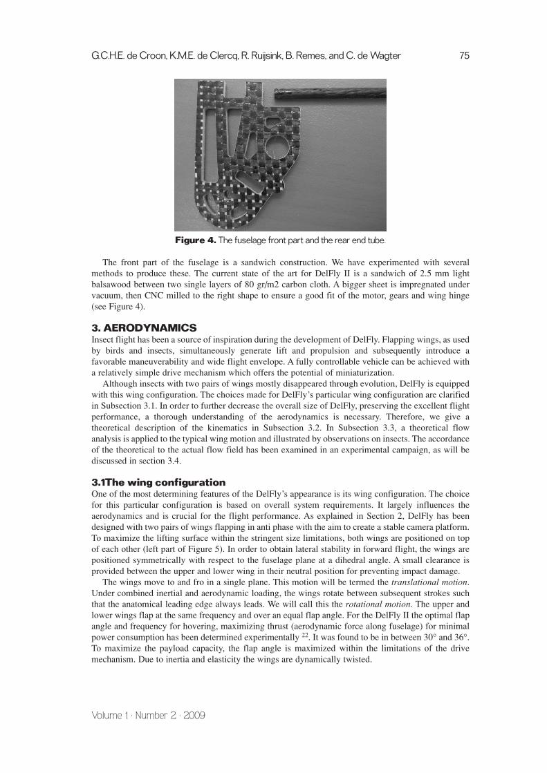
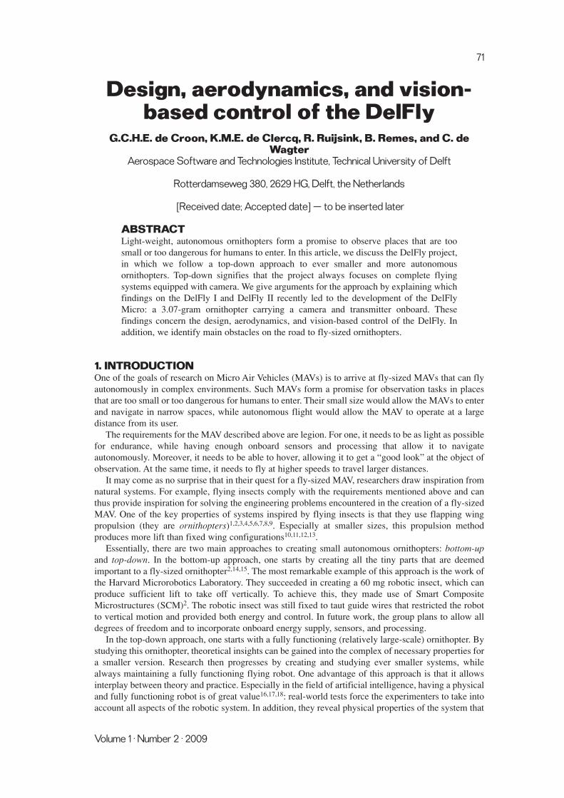
Figure 4. The fuselage front part and the rear end tube.
The front part of the fuselage is a sandwich construction. We have experimented with severalmethods to produce these. The current state of the art for DelFly II is a sandwich of 2.5 mm lightbalsawood between two single layers of 80 gr/m2 carbon cloth. A bigger sheet is impregnated undervacuum, then CNC milled to the right shape to ensure a good fit of the motor, gears and wing hinge(see Figure 4).
3. AERODYNAMICSInsect flight has been a source of inspiration during the development of DelFly. Flapping wings, as usedby birds and insects, simultaneously generate lift and propulsion and subsequently introduce afavorable maneuverability and wide flight envelope. A fully controllable vehicle can be achieved witha relatively simple drive mechanism which offers the potential of miniaturization.
Although insects with two pairs of wings mostly disappeared through evolution, DelFly is equippedwith this wing configuration. The choices made for DelFly’s particular wing configuration are clarifiedin Subsection 3.1. In order to further decrease the overall size of DelFly, preserving the excellent flightperformance, a thorough understanding of the aerodynamics is necessary. Therefore, we give atheoretical description of the kinematics in Subsection 3.2. In Subsection 3.3, a theoretical flowanalysis is applied to the typical wing motion and illustrated by observations on insects. The accordanceof the theoretical to the actual flow field has been examined in an experimental campaign, as will bediscussed in section 3.4.
3.1The wing configuration One of the most determining features of the DelFly’s appearance is its wing configuration. The choicefor this particular configuration is based on overall system requirements. It largely influences theaerodynamics and is crucial for the flight performance. As explained in Section 2, DelFly has beendesigned with two pairs of wings flapping in anti phase with the aim to create a stable camera platform.To maximize the lifting surface within the stringent size limitations, both wings are positioned on topof each other (left part of Figure 5). In order to obtain lateral stability in forward flight, the wings arepositioned symmetrically with respect to the fuselage plane at a dihedral angle. A small clearance isprovided between the upper and lower wing in their neutral position for preventing impact damage.
The wings move to and fro in a single plane. This motion will be termed the translational motion.Under combined inertial and aerodynamic loading, the wings rotate between subsequent strokes suchthat the anatomical leading edge always leads. We will call this the rotational motion. The upper andlower wings flap at the same frequency and over an equal flap angle. For the DelFly II the optimal flapangle and frequency for hovering, maximizing thrust (aerodynamic force along fuselage) for minimalpower consumption has been determined experimentally 22. It was found to be in between 30° and 36°.To maximize the payload capacity, the flap angle is maximized within the limitations of the drivemechanism. Due to inertia and elasticity the wings are dynamically twisted.
G.C.H.E. de Croon, K.M.E. de Clercq, R. Ruijsink, B. Remes, and C. de Wagter 75
Volume 1 · Number 2 · 2009
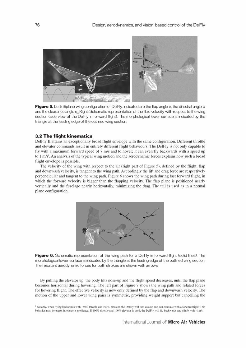
Figure 5. Left: Biplane wing configuration of DelFly. Indicated are the flap angle ϕ, the dihedral angle ψand the clearance angle ϕs Right: Schematic representation of the fluid velocity with respect to the wingsection (side view of the DelFly in forward flight). The morphological lower surface is indicated by thetriangle at the leading edge of the outlined wing section.
3.2 The flight kinematicsDelFly II attains an exceptionally broad flight envelope with the same configuration. Different throttleand elevator commands result in entirely different flight behaviours. The DelFly is not only capable tofly with a maximum forward speed of 7 m/s and to hover; it can even fly backwards with a speed upto 1 m/si. An analysis of the typical wing motion and the aerodynamic forces explains how such a broadflight envelope is possible.
The velocity of the wing with respect to the air (right part of Figure 5), defined by the flight, flapand downwash velocity, is tangent to the wing path. Accordingly the lift and drag force are respectivelyperpendicular and tangent to the wing path. Figure 6 shows the wing path during fast forward flight, inwhich the forward velocity is bigger than the flapping velocity. The flap plane is positioned nearlyvertically and the fuselage nearly horizontally, minimizing the drag. The tail is used as in a normalplane configuration.
Figure 6. Schematic representation of the wing path for a DelFly in forward flight (solid lines). Themorphological lower surface is indicated by the triangle at the leading edge of the outlined wing section.The resultant aerodynamic forces for both strokes are shown with arrows.
By pulling the elevator up, the body tilts nose-up and the flight speed decreases, until the flap planebecomes horizontal during hovering. The left part of Figure 7 shows the wing path and related forcesfor hovering flight. The effective velocity is now only defined by the flap and downwash velocity. Themotion of the upper and lower wing pairs is symmetric, providing weight support but cancelling the
76 Design, aerodynamics, and vision-based control of the DelFly
International Journal of Micro Air Vehicles
1 Notably, when flying backwards with ~80% throttle and 100% elevator, the DelFly will turn around and can continue with a forward flight. Thisbehavior may be useful in obstacle avoidance. If 100% throttle and 100% elevator is used, the DelFly will fly backwards and climb with ~1m/s.

horizontal aerodynamic force. In hovering flight, the direction of the fluid velocity with respect to thewing section and the aerodynamic forces are symmetric for the upper and the lower wing. The arrowsassociated with the top right and bottom left wing section show that the anatomical lower wing surface,indicated by the triangle, does not always act as the aerodynamic lower surface.
Figure 7. Left: Schematic representation of the wing path for a hovering DelFly. The morphologicallower surface is indicated by the triangle at the leading edge of the outlined wing section. The resultantaerodynamic forces for both strokes are shown with arrows. Right: Schematic representation of thestreamlines over time due to (a) Kutta condition, (b) Kelvin’s theorem, and (c) dynamic stall.
3.3 Unsteady aerodynamicsCompared to steady airfoils, flapping wings are able to generate high lift coefficients due to unsteadyaerodynamics. The lift enhancement has been attributed to specific fluid structures that occur duringthe different phases of the flap cycle23. Below, the role of these effects will be theoretically discussedand illustrated by observations on animals. Distinction will be made between the translational androtational motion.
3.3.1 Translational motionAfter rotation the wing is impulsively started in the translational phase. Air swirls around the sharptrailing edge introducing a region of intense vorticity (a in the right part of Figure 7, time t). Kelvin’scirculation theoremxiii states that the time rate of change of circulation around a closed curve consistingof the same fluid elements is zero (b in the right part of Figure 7). Therefore a vortex, equal in strengthbut opposite in direction, is generated around the airfoil. The high-vorticity region moves downstreamof the trailing edge and tends to roll up into a concentrated starting vortex As long as vorticity is shedfrom the trailing edge, the starting vortex grows stronger and so does the bound vortex, until the Kuttacondition24 is satisfied (a in Figure 7, t+∆t). This gradual build-up of circulation is called the Wagnereffect25. Since the strength of the bound vortex is directly proportional to the velocity difference overthe airfoil section, the build-up of vorticity is a measure of the increase in lift force generated per unitspan. Because the total distance travelled by the wings during a half stroke is small, the circulationgrowing in a manner similar to Wagner’s theory will remain lower than the steady value. Generally, therequired lift to support body weight in flapping flight is larger than the lift producible by the wings insteady-motion. A source of additional lift has to be found.
Since the wings are impulsively started at an angle of attack higher than the stall angle, thephenomenon called dynamic or delayed stall12 is expected. The separation associated with stallbecomes well-developed (c in Figure 7, t+∆t), if the wing travels several chord lengths. During the briefperiod between t and t+∆t, the circulation, and thus the lift, exceeds the maximum quasi-steady stalledvalue. The circulation starts to grow at the beginning of the translational stroke and is proportional tothe product of the chord and the span wise location32. The steady-state stall will not be reached if thestroke length covers only a few chords, as is the case for flapping wings.
When the translational wing motion stops at the end of the stroke, no lift or circulation should beleft. The bound vortex swirls off the trailing edge, shedding as a stopping vortex (Figure 8). In the same
G.C.H.E. de Croon, K.M.E. de Clercq, R. Ruijsink, B. Remes, and C. de Wagter 77
Volume 1 · Number 2 · 2009
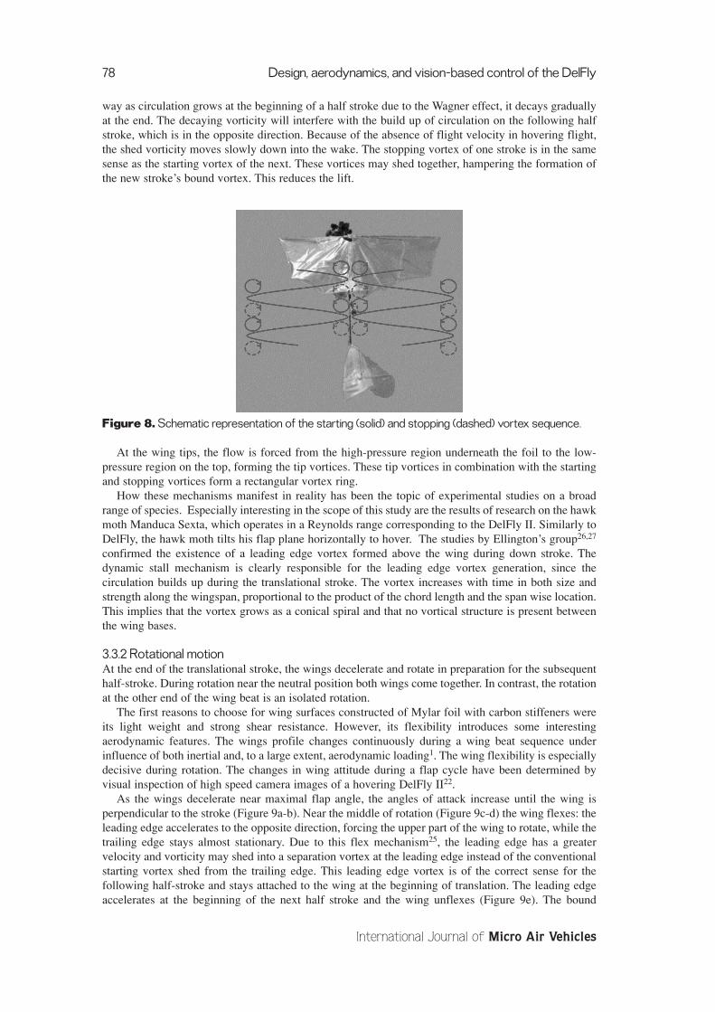
way as circulation grows at the beginning of a half stroke due to the Wagner effect, it decays graduallyat the end. The decaying vorticity will interfere with the build up of circulation on the following halfstroke, which is in the opposite direction. Because of the absence of flight velocity in hovering flight,the shed vorticity moves slowly down into the wake. The stopping vortex of one stroke is in the samesense as the starting vortex of the next. These vortices may shed together, hampering the formation ofthe new stroke’s bound vortex. This reduces the lift.
Figure 8. Schematic representation of the starting (solid) and stopping (dashed) vortex sequence.
At the wing tips, the flow is forced from the high-pressure region underneath the foil to the low-pressure region on the top, forming the tip vortices. These tip vortices in combination with the startingand stopping vortices form a rectangular vortex ring.
How these mechanisms manifest in reality has been the topic of experimental studies on a broadrange of species. Especially interesting in the scope of this study are the results of research on the hawkmoth Manduca Sexta, which operates in a Reynolds range corresponding to the DelFly II. Similarly toDelFly, the hawk moth tilts his flap plane horizontally to hover. The studies by Ellington’s group26,27
confirmed the existence of a leading edge vortex formed above the wing during down stroke. Thedynamic stall mechanism is clearly responsible for the leading edge vortex generation, since thecirculation builds up during the translational stroke. The vortex increases with time in both size andstrength along the wingspan, proportional to the product of the chord length and the span wise location.This implies that the vortex grows as a conical spiral and that no vortical structure is present betweenthe wing bases.
3.3.2 Rotational motionAt the end of the translational stroke, the wings decelerate and rotate in preparation for the subsequenthalf-stroke. During rotation near the neutral position both wings come together. In contrast, the rotationat the other end of the wing beat is an isolated rotation.
The first reasons to choose for wing surfaces constructed of Mylar foil with carbon stiffeners wereits light weight and strong shear resistance. However, its flexibility introduces some interestingaerodynamic features. The wings profile changes continuously during a wing beat sequence underinfluence of both inertial and, to a large extent, aerodynamic loading1. The wing flexibility is especiallydecisive during rotation. The changes in wing attitude during a flap cycle have been determined byvisual inspection of high speed camera images of a hovering DelFly II22.
As the wings decelerate near maximal flap angle, the angles of attack increase until the wing isperpendicular to the stroke (Figure 9a-b). Near the middle of rotation (Figure 9c-d) the wing flexes: theleading edge accelerates to the opposite direction, forcing the upper part of the wing to rotate, while thetrailing edge stays almost stationary. Due to this flex mechanism25, the leading edge has a greatervelocity and vorticity may shed into a separation vortex at the leading edge instead of the conventionalstarting vortex shed from the trailing edge. This leading edge vortex is of the correct sense for thefollowing half-stroke and stays attached to the wing at the beginning of translation. The leading edgeaccelerates at the beginning of the next half stroke and the wing unflexes (Figure 9e). The bound
78 Design, aerodynamics, and vision-based control of the DelFly
International Journal of Micro Air Vehicles

vorticity is likely to roll up around the stationary trailing edge and shed as a combined starting andstopping vortex when the wing unflexes. This mechanism would provide the wing with a net circulationat the beginning of the following half stroke, which skips the gradual increase of lift.
Figure 9. Schematic representation of the flex mechanism. The dot on the outlined wing section isindicating the location of the leading edge. The arrows represent the streamlines. The dashed line is at afixed position in space.
Smoke visualization with tethered Manduca Sexta moths26 investigated the use of the flexmechanism at the end of the down stroke. At the moment that the leading edge starts to rotate, the fore-and hind-wings flex. The increase in the velocity at the leading edge induces vortex shedding at theanatomic lower surface. This new leading edge vortex is in the correct sense as to enhance the boundcirculation during the subsequent stroke. However, it does not remain attached to the wing.
Near minimal flap angle, the angles of attack increase as the wings decelerate and the upper andlower wings touch along their surfaces. First the leading edges approach, the wings curve along theircamber and the meeting point smoothly moves along the wing surfaces towards the trailing edges, assketched in Figure 10a-d. By expelling air downwards, this clap mechanism28 may produce amomentum jet augmenting lift. Otherwise the lift enhancement could be interpreted as a method toextend lift generation till the clap is completed. Since both wings’ bound vorticity is equal in strengthbut opposite in sign, Kelvin’s theorem applies without the need for a stopping vortex to be shed.
Figure 10. Schematic representation of the clap and peel mechanism. The dot on the outlined wingsection is indicating the location of the leading edge. The arrows represent the streamlines. The dashedline represents the neutral position of the wings.
Already before the clap has been completed, the leading edges start separating again, the wingscurve towards the opposite side and the surfaces peel apart, as can be seen in Figure 10e-f. Due to thispeel, fluid flows over the wing surfaces into the opening gap creating a circulation in opposite directionaround both wing28. The circulation is expected to grow linearly with the distance from leading edgeto separation point25. No starting vortices would be shed, since the bound vortex of one wing acts asthe starting vortex of the other one. As the wings separate and move apart in the next stroke, enhancedlift would immediately be generated from the fling circulation, circumventing the gradual growth anddecay of circulation by the Wagner effect.
Examples of insects using clap and fling as lift enhancement mechanism typically operate in a lowerReynolds range. On a dynamically scaled robotic model of a fruit fly, Lehmann29 recently investigatedlift enhancement due to the fling mechanism. The clap mechanism was found to attenuate lift force. Onthe same model, Poelma30 demonstrated the existence of leading and trailing edge vortices.
G.C.H.E. de Croon, K.M.E. de Clercq, R. Ruijsink, B. Remes, and C. de Wagter 79
Volume 1 · Number 2 · 2009
3.4 Experimental resultsRecently, we performed experiments on a full-scale and non-simplified model of DelFly II to verify theexistence of lift enhancing vortex structures, as could be expected from the previous theoreticaldiscussion. Here, we briefly discuss the main experiments and results. For a more extensive discussionof these experiments, we refer the reader to 31. The data obtained in this study will be evaluated tocontribute to the improvement of the aerodynamic characteristics of DelFly.
Since DelFly II differs from typical insects and birds in wing configuration, flapping frequency andwing size, only a restricted similarity in flow-field behavior is expected. The effects of complex wingkinematics, three-dimensional flow and fluid-structure interaction as a result of high wing flexibilityare inseparably linked in the fluid dynamics behavior of DelFly II.
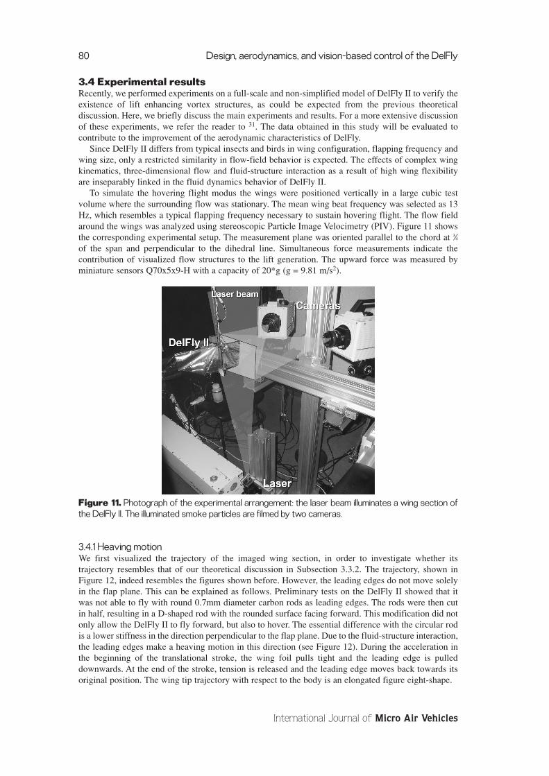
To simulate the hovering flight modus the wings were positioned vertically in a large cubic testvolume where the surrounding flow was stationary. The mean wing beat frequency was selected as 13Hz, which resembles a typical flapping frequency necessary to sustain hovering flight. The flow fieldaround the wings was analyzed using stereoscopic Particle Image Velocimetry (PIV). Figure 11 showsthe corresponding experimental setup. The measurement plane was oriented parallel to the chord at 3⁄4of the span and perpendicular to the dihedral line. Simultaneous force measurements indicate thecontribution of visualized flow structures to the lift generation. The upward force was measured byminiature sensors Q70x5x9-H with a capacity of 20*g (g = 9.81 m/s2).
Figure 11. Photograph of the experimental arrangement: the laser beam illuminates a wing section ofthe DelFly II. The illuminated smoke particles are filmed by two cameras.
3.4.1 Heaving motionWe first visualized the trajectory of the imaged wing section, in order to investigate whether itstrajectory resembles that of our theoretical discussion in Subsection 3.3.2. The trajectory, shown inFigure 12, indeed resembles the figures shown before. However, the leading edges do not move solelyin the flap plane. This can be explained as follows. Preliminary tests on the DelFly II showed that itwas not able to fly with round 0.7mm diameter carbon rods as leading edges. The rods were then cutin half, resulting in a D-shaped rod with the rounded surface facing forward. This modification did notonly allow the DelFly II to fly forward, but also to hover. The essential difference with the circular rodis a lower stiffness in the direction perpendicular to the flap plane. Due to the fluid-structure interaction,the leading edges make a heaving motion in this direction (see Figure 12). During the acceleration inthe beginning of the translational stroke, the wing foil pulls tight and the leading edge is pulleddownwards. At the end of the stroke, tension is released and the leading edge moves back towards itsoriginal position. The wing tip trajectory with respect to the body is an elongated figure eight-shape.
80 Design, aerodynamics, and vision-based control of the DelFly
International Journal of Micro Air Vehicles

Figure 12. Schematic representation of the wing motion during one flap cycle. Instantaneous wingposition and attitude is sketched with respect to the non-dimensional time. In- and outstroke arerepresented by upper and lower part respectively.
Similar wing paths have been observed for various insects32. Thanks to the upward motion duringclap, the foil is pulled tight during the rotation. The downward leading edge motion during peel mightreinforce the leading edge vortex generation by increasing the velocity of the fluid moving into theopening gap33.
3.4.2 Flow field analysisThe results of the flow field analysis reveal that the most important augmentation in lift generation inthe current test configuration of DelFly II is due to the inrush of air into the opening gap during thefling31. The occurrence of a leading edge vortex during fling cannot be assessed unambiguously fromthe PIV result because of the poor accuracy near the wings, but is doubtful since the inrush of airdecreases the angle of attack considerably. Contrary to the expectation in our theoretical discussion, wedid observe starting vortices at the end of the peel.
Another significant contribution to the lift generation might be the generation of a leading edgevortex at isolated wing rotation. The expected expelling jet during clap could not be observed. This isattributed to the high flexibility of the wing foil. More details on these results can be found in 31.
Based on the absence of an expelling jet during clap, it is suspected that a better aerodynamicperformance of the DelFly could be attained by more rigid wing surfaces. This would increase thepositive contribution of the clap mechanism to the lift generation without disturbing the favorable flingeffect.
4. ELECTRONICSThere is no combination of off-the-shelf components that can be used for the electronics of ornithoptersas small as the DelFly II and the DelFly Micro. In this section, we describe the various electroniccomponents of the DelFly: the power source (Subsection 4.1), the motor (Subsection 4.2), the radiocontrol system (Subsection 4.3), and the video system (Subsection 4.4). We explain how we improvedsome of the components over time for optimizing their performance on our flapping wing platform.
G.C.H.E. de Croon, K.M.E. de Clercq, R. Ruijsink, B. Remes, and C. de Wagter 81
Volume 1 · Number 2 · 2009

4.1 The Power SourceThe power source to the ornithopter is an important design aspect. Its power- and energy density iscrucial for the performance. As the absolute weight of the power source is very low many technologiesthat can be used in big scale are not feasible in the scale of a Micro Air Vehicle, let alone a Nano AirVehicle (NAV). Fuel cells, nuclear generators, internal combustion engines, and many others are not(yet) applicable at this scale.
Disposable or rechargeable batteries have reached performance levels that allow successful flightscenarios. In the Delfly we use the easily available rechargeable Lithium Polymer batteries. The latesttypes of these batteries can deliver an energy density of 170 Wh/Kg and a power density of 4000 W/Kgsustained. The versions in the mass range of 1 to 4 gram, relevant for MAVs and NAVs are less efficientbut still attain 130 Wh/Kg respectively 2600W/Kg. More modern battery concepts as the LithiumSulphur type can almost double the energy density but they still do not match the required powerdensity.
4.2 The MotorWhen the power source is electric the drive motor is also electric. We first explain the drive mechanismon the DelFly. Then, we describe the consequences of this choice on our design of the motor.
4.2.1 Drive MechanismIn an ornithopter we need an oscillating movement of the wings, with a frequency of between 8 and 50Hz, depending on vehicle size and flight regime. One could employ actuators that directly produce alinear movement with a suitable force. However, this leads to the following problem. In almost allelectric to mechanic conversion, the size and mass of the system are proportional to the force.Therefore, the power should be proportional to the force times the desired frequency. To reach a goodpower at low mass we need a high frequency at a low force. This cannot be achieved with conventionallinear or reciprocating actuators.
Still the best solution yielding a favorable power density, we have found, is a high RPM electricmotor with a gear set to match the rpm and the flapping frequency plus a crank mechanism.
4.2.2 Development of the MotorThe DelFly I featured a small coreless pager motor (MK07-2.3 red34). The problem of this motor wasthat it would in general provide only a few minutes of sustained flight, and usually wore out within anhour. The reason for this was the low efficiency of 35%, which led to overheating and expansion of therotor inside the motor.
For the DelFly II we developed a brushless motor that matches the requirements in an ornithopter,in collaboration with the company DC Enterprises in India35. The resulting brushless motor was moreefficient than the motor on the DelFly I, and delivered enough mechanical power to be able to hover(> 1.5 Watts or > 1kW / kg).
Figure 13. Image of a brushless motor.
A brushless motor (see Figure 13) can reach higher efficiencies and higher power densities thanconventional brushed motors. In addition, there are no other wearing parts than the (ball) bearings. Thismakes the reliability of the motors several orders of magnitude better than their brushed brothers.
A brushless motor has a stator with 3 electric phases and an electronic controller produces arevolving electro-magnetic field. This makes the magnet rotor rotate. The timing of the controller can
82 Design, aerodynamics, and vision-based control of the DelFly
International Journal of Micro Air Vehicles

be accomplished with magnetic sensors, which yields a well determined positional feedback of therotor. These sensors can be avoided in more sophisticated controllers where the position of the rotor inrelation to the stator phase is measured by means of the EMF voltage from the non-energized winding.The timing can be determined well when the motor runs smoothly with a constant or slowly changingrpm.
In the development of the DelFly motor and controller we have found that the determination of thetiming is hampered by two aspects of uneven rotation.
1. The first prototype of the motor did run very well with a propeller but would not run smoothlywith the flywheel effect of only a small polyacetal pinion on the axle. This is the uneven runningwithin one rotation of the motor.
2. The first problem resolved there was the uneven load during one flapping cycle. Near the pointwhere the flapping direction changes, the load on the motor changes abruptly also leading totiming difficulties.
The first problem was that the cogging torque of the motor produces a very swift speed changewithin each cycle of the rotation. At high rpm the timing was adequate, but the motor would not run atmedium and low speeds necessary for our drive mechanism. In collaboration with Dr. E. Lomonova ofthe Eindhoven University we have made a magnetic simulation of the motor to find ways of reducingthe cogging torque. With the help of simulations, we studied whether it was possible to reduce thecogging torque by varying the magnetic structure of the motor, the number of magnets, and themagnetic embracement: the percentage covered by magnets over the circumference of the rotor.
The original motor had 3 x 3 = 9 stator phases and 12 magnetic poles and a magnetic embracementof 100%. The embracement can be varied gradually by changing the sizes of the magnets in the motor.The left part of Figure 14 shows the relation between the embracement (in %, x-axis) and the efficiency(in %, left y-axis) and cogging torque (in N*mm, right y-axis). The simulation showed that reducing theembracement would also reduce the cogging torque. A minimum cogging torque was realized with anembracement of 64%. It decreased significantly, from 330 Nmm to 17 Nmm. However, the efficiencyof the motor would also decrease from 59% to 52%, which was not what we were looking for.
Another option to reduce cogging torque was to change the magnetic structure of the brushlessmotor. Brushless motors can be made with a vast range of phase-pole combinations, some excellent,some marginal. The 9 phase-12 pole and 12 phase-14 pole approach are the most common but otherscan behave well. A 9 phase-10 pole version was simulated and found to be very suitable.
The simulations showed that an embracement of 83% would lead to almost zero cogging torque withan efficiency as high as the original motor. This could be achieved with 10 of the original 12 magnetsspaced evenly around the circumference of the rotor, with an embracement of ~83%. Without newtooling, an extremely low cogging torque was promised with an equally high efficiency as the baseversion (while maintaining the same rpm of the electromagnetic field). Due to the reduced number ofmagnets the actual mechanical rpm was 20% higher (see the right part of Figure 14). This formed noproblem, as a two stage gearing was needed anyway and only the ratio had to change. In addition, thewinding scheme for a 10 pole motor is different from the 12 pole version but that was easilyimplemented.
Figure 14. Left: Effect of the embracement on the efficiency and the cogging torque. Right: Efficiencyvs. shaft rpm for different brushless motor configurations
G.C.H.E. de Croon, K.M.E. de Clercq, R. Ruijsink, B. Remes, and C. de Wagter 83
Volume 1 · Number 2 · 2009

The second timing problem was caused by the uneven load during the flapping cycle of theornithopter. The quick load changes are problematic for the commutation of the motor as it has to takeplace some 20° before zero crossing of the EMF signals. When the motor speeds up too quickly thismay lead to ‘misfiring’. To solve this problem, we cooperated with both Micro Plane Solutions ofFrance and MicroInvent of Slovakia. The solution involved both the hardware and the software of themotor controller. The EMF voltages needed to be measured more accurately by the hardware, and themeasurements needed to be filtered differently by the software. In particular, there was a largeremphasis on measurements with respect to the predictions. The resulting controller is shown in the leftpart of Figure 15.
Figure 15. Left: Motor controller designed with Micro Plane Solutions of France and MicroInvent ofSlovakia, in order to cope with the uneven load during one flapping cycle.
Right: The gears as used on the DelFly II.
To match the maximum required flapping frequency with the rpm range of the electric motor a gearratio of 20:1 has been adopted. The gears are from polyacetal and have a module of 0.3. We have a 12teeth pinion on the motor a 48/12 teeth idler gear. On the 60 teeth final gear a dual crank is fitted toactuate the two sets of wings (see right part of Figure 15). The motor we use is not the same as itscommercial version, the Mighty Midget Nano35.
4.3 The Radio Control SystemA solid control of an MAV is equally important as a low weight. For the DelFly I, we have used thefirst version of a commercial 900 MHz system by Plantraco. This resulted in good control, but also inmany small problems. These problems included: a way too low PWM frequency to power the then usedbrushed pager motor, no current limit on the actuator outputs made it not enough foolproof, awkwardfrequency control, and low quality transmitter sticks. Still, the system had as main advantage that it wasvery light.
Consequently, when designing the DelFly II, we searched for a different kind of system. When theMicroInvent Minor receivers came on the market we used them in conjunction with our standard 35MHz transmitters. These receivers are very versatile and can be used with all kind of actuator and motortypes.
Recently we are changing to a modified 2nd version Plantraco system. The Martin Newell “Rabbit”HipHop system, operates still on 868 or 900 MHz, but now with different soft and hardware. It is lightto extremely light, and without all the problems we have encountered before. The system uses afrequency hopping algorithm to avoid any problem that could arise from frequency clashes, whenflying in halls or during shows. The transmitter used is a HF module that couples to a decent transmitterfront-end.
4.4 ActuatorsThe rudder and elevator of the DelFly are actuated by magnetic actuators (see Figure 16). At the
beginning of the DelFly project these were the only systems of under one gram to provide adequatecontrol. Conventional servos were available with a mass of around 2 grams at that time. Currently thereare more options emerging, such as light-weight muscle-wire or Piezo actuators. Muscle-wire is aShape Memory Alloy (SMA), which can become smaller by applying heat to it. Although it is inprinciple promising for light-weight actuation of ornithopters, its response time is currently too long foroptimal control36 and the efficiency is too low. Piezo actuators are more efficient, but still have too highvoltage requirements for the batteries onboard the DelFly. The employed magnetic actuators offer just
84 Design, aerodynamics, and vision-based control of the DelFly
International Journal of Micro Air Vehicles
enough control power, at a reasonably low weight and power consumption. They provide a smooth andfully proportional control. The actuators are the Plantraco MiniACT37.
Figure 16. Magnetic actuators on the DelFly II.
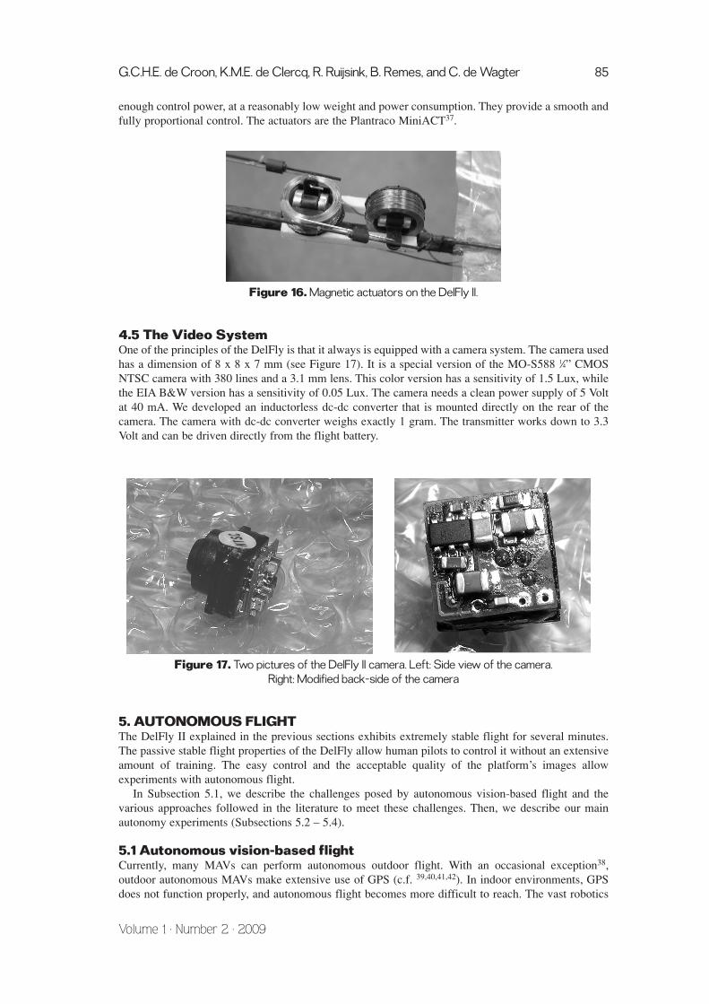
4.5 The Video SystemOne of the principles of the DelFly is that it always is equipped with a camera system. The camera usedhas a dimension of 8 x 8 x 7 mm (see Figure 17). It is a special version of the MO-S588 1⁄4” CMOSNTSC camera with 380 lines and a 3.1 mm lens. This color version has a sensitivity of 1.5 Lux, whilethe EIA B&W version has a sensitivity of 0.05 Lux. The camera needs a clean power supply of 5 Voltat 40 mA. We developed an inductorless dc-dc converter that is mounted directly on the rear of thecamera. The camera with dc-dc converter weighs exactly 1 gram. The transmitter works down to 3.3Volt and can be driven directly from the flight battery.
Figure 17. Two pictures of the DelFly II camera. Left: Side view of the camera.Right: Modified back-side of the camera
5. AUTONOMOUS FLIGHTThe DelFly II explained in the previous sections exhibits extremely stable flight for several minutes.The passive stable flight properties of the DelFly allow human pilots to control it without an extensiveamount of training. The easy control and the acceptable quality of the platform’s images allowexperiments with autonomous flight.
In Subsection 5.1, we describe the challenges posed by autonomous vision-based flight and thevarious approaches followed in the literature to meet these challenges. Then, we describe our mainautonomy experiments (Subsections 5.2 – 5.4).
5.1 Autonomous vision-based flightCurrently, many MAVs can perform autonomous outdoor flight. With an occasional exception38,outdoor autonomous MAVs make extensive use of GPS (c.f. 39,40,41,42). In indoor environments, GPSdoes not function properly, and autonomous flight becomes more difficult to reach. The vast robotics
G.C.H.E. de Croon, K.M.E. de Clercq, R. Ruijsink, B. Remes, and C. de Wagter 85
Volume 1 · Number 2 · 2009
literature cannot deliver ready-made solutions, since most autonomous robotic experiments have beenperformed with ground-based robots. Such robots face an inherently different problem than MAVs:taking no action will in general not cause harm to a ground-based robot, but will cause unpleasantencounters with walls, floor, or other obstacles for a flying MAV. In addition, ground-based robots cancarry more and heavier sensors than MAVs. Infrared sensors and laser range finders are abundantlyused in ground robotics (c.f. 43). However, any sensor mounted on an MAV has to be traded off againstother sensors.
All DelFlys have as sole sensor a video camera. The motivation for this choice is that a camera is arelatively light sensor for the amount of information that it can provide. In addition, camera images areeasy to interpret for human observers. In the literature, there are three main approaches to reachingcamera-based autonomous flight.
The first approach is to control an MAV with the help of external cameras (e.g., 44,45). The imagesof the external cameras are used to detect different parts of the MAV. The exact position of these partscan be determined by triangulation methods and from these positions, the attitude of the MAV can bedetermined. With a measurement of the attitude of the MAV, it becomes possible to control evenpassively unstable MAVs such as helicopters. The first approach is the most successful, but also themost limited one: the MAV will only be able to fly in spaces in which there are (known) fixed cameras.Any exploration of unknown areas is thus impossible with this approach.
The second approach uses the onboard camera to accurately estimate the state of the MAV (3Dposition, pitch, yaw, and roll). Such a state estimate can be obtained by using a 3D model of theenvironment, which can either be prefabricated 46 or learned 47,48. There is an increasing number ofcomputer vision algorithms that succeed in building a model of the environment. However, they arecurrently still computationally expensive. Therefore, when entering a new room, the state estimation ofthe MAV does not work immediately. Remark that not all studies of this approach use an accurate 3D-model of the world to obtain an accurate estimate. Instead, some studies make specific assumptions onthe space in which the MAV is flying. For example, state estimation can be performed with the help of`vanishing points’ 49. The vanishing points can be determined on the basis of parallel lines that are insight. The method assumes that such lines are known and are in the field of view.
The third approach is a more bio-inspired approach to autonomous flight. Studies of this approachtypically abandon a state estimate altogether and focus on training the right responses to incomingvisual inputs. For example, in 50 optic flow is used in an onboard sensing and processing scheme toavoid walls on which special black-and-white textures were projected. The measured flow is directlycoupled to the steering commands of the micro flyer. Studies of the third approach generally exploitoptic flow (cf.51,52,53), and currently work best in textured environments. The reason for this is that boththe optics and the optic flow algorithms are still outperformed by their natural counterparts.
In our research we have drawn inspiration from all of the approaches above. In the next subsections,we report on three experiments and their results. As mentioned above, the DelFly is a passively stableMAV. Therefore, in our autonomy experiments we have limited ourselves to algorithms for controllingheight and direction. The experiments we performed are: height control with an external camera(Subsection 5.2), height and direction control with a path-tracking algorithm (Subsection 5.3), andheight control with an appearance-based algorithm (Subsection 5.4).
5.2 External camera algorithmWe performed our first autonomy experiment with the DelFly II with an external camera. Theexperiment had one main goal: to verify whether a good height estimate from external camera imageswould suffice for achieving height control. A height estimation algorithm for an external camera is easyto implement, reliable, and requires little computational effort. In addition, the external camera isdirectly connected to the computer performing the computational processing so that there is only asmall delay in image transmission. For these reasons, the success of this experiment was a vital steptowards more demanding algorithms that process the onboard images.
The experiment started with the pilot in full control of the DelFly. After trimming the throttle, hepushed the fire button to hand over throttle control to the height controller. The height controller firstestimated the height of the DelFly with the following straightforward height estimation algorithm (seealso Figure 18). The algorithm subtracted subsequent grayscale images from each other and applied athreshold to the result, in order to detect motion in the field of view. Then, the y-coordinates of allmotion pixels were sorted to determine the median y-coordinate of the motion in the image. During the
86 Design, aerodynamics, and vision-based control of the DelFly
International Journal of Micro Air Vehicles

experiment, only the DelFly moved in the field of view. The y-coordinate was scaled to the interval [-1,1], with 1 mapping to the top of the image and -1 to the bottom. Instead of attempting to calculate theexact height of the DelFly, the scaled y-coordinate was used as the error value for a regulator of thethrottle. The regulator was a P-controller.
Figure 18. Illustration of the external camera algorithm. Two images captured at subsequent time stepsare subtracted from each other, and thresholded. Then we estimate the median y-coordinate in theresulting binary motion mask.
Movies of two of the experiments can be seen online19. Figure 19 shows the median y-coordinateover time for the experiment of movie ‘webcam2.avi’. Two peculiarities can be seen in the graph: (1)if no motion is present in the image, the output does not change (flat lines), and (2) if the DelFly leavesthe image, the line will go flat and the DelFly will continue flying with the same throttle command.Therefore, if it leaves the view under the zero-level, it will usually return in view above the zero-level(abrupt changes in y-coordinate). However, for most of the run, the graph is smooth and the DelFlyadjusts its throttle well in accordance to the y-estimates.
Figure 19. Median y-coordinate (y in [-1,1]) over time (~30ms per time step) for ‘webcam2.avi’.
The above setup resulted in successful autonomous height control. During the flight, the pilot onlyhad to steer the DelFly to keep it in the view of the webcam used as external camera. Importantly, a P-controller already sufficed for achieving height control.
5.3 Path-tracking algorithmThe second autonomy experiment had as main goal to test whether it was possible to achieve bothheight and direction control in a setting with onboard images. The bare minimum for full path controlof a DelFly consists of 3 measurements. First, we need to estimate the height of the DelFly. The verylow wing loading of DelFly makes it very well damped, so height measurements at more than about5Hz are sufficient to stabilize its altitude within +/- 50cm. Second, the DelFly needs a measurement ofthe desired heading, in order to navigate to a point of interest. We cannot control the rudder only on thebasis of this desired heading, since the DelFly is spiral unstable. So, third, we need to measure andcontrol the turn rate. This is especially necessary for performing any sharp turns.
For the experiment, we designed an algorithm relying on the presence of a visible line on the ground,consisting of connected A4 papers (210 x 297 mm). The fixed size of the A4-papers was used fordetermining the height of the DelFly. The paper line itself was used as the path to follow. The reasonfor choosing a line was the image analysis simplicity and the fact that it easily applies to many buildingswith long corridors, where seen from above the ground looks like a big line to follow in between thewalls. In this experiment, the DelFly II had a dual camera setup with one camera pointing down andthe other pointing forward. Two identical black and white cameras were used, since they have twenty
G.C.H.E. de Croon, K.M.E. de Clercq, R. Ruijsink, B. Remes, and C. de Wagter 87
Volume 1 · Number 2 · 2009

times better light sensitivity than color cameras. Below, we explain how we determined the height,desired heading, and turn rate from both cameras’ images (see also Figure 20).
Figure 20. Illustration of image processing for the path-tracking algorithm. Left: the downward imageis processed in two parallel ways to estimate the height (h), the desired relative heading (∆ψ), and thelateral offset (∆x). Right: Two subsequent forward images are processed to estimate the turn rate (r).See the text for more detail.
As mentioned, the fixed size of the A4 papers can be used for estimating the height. If the paper isin the centre of the view (no lateral offset), the height h is related to the observed width of the a4 paperspwA4 (in pixels) as:
(1)
where wA4 is the width of an A4-sized paper in centimeters, v is the field of view in degrees, pwIm isthe width of the image in pixels, and θ and ϕ are the pitch and roll, respectively. Linearizing aroundzero pitch and zero roll simplifies this equation to:
(2)
Assuming a straight paper line running from the bottom to the top of the image, the surface of theline scales linearly with the width giving the final equation for height:
(3)
where phIm is the height of the image in pixels and c is the total number of paper pixels in view.Therefore, to estimate the height, we only need to measure the number of pixels in view belonging tothe paper line. This was achieved by thresholding the image and counting the remaining pixels.
The desired heading was also obtained by processing the bottom image. We first performed Cannyedge detection and then applied a coarse Hough line-detector (with 10 pixels and 5 degrees) in order tofind the sides of the connected papers. Only detected lines pointing upwards within a 45 degree marginwere used for estimation. Hence, horizontal lines were left out. Averaging the remaining lines gave theheading of the DelFly relative to the path ∆ψ, and the lateral offset of the paper path ∆x.
Finally, the turn rate r was estimated with the help of subsequent images from the forward-pointingcamera. Optic flow was computed on the images using the fast Lucas-Kanade algorithm54 on a set of40 corners in a 128 x 128 pixel resized image. Averaging the horizontal component of the optic flowresults in a measure for the turn rate r.
hw p p
vcA h w=
4 Im Im /
hw p
p vA w
wA
=( )
Im4
4
hw
p v
p
A
wA
w
=
( / )
tan( / )( / )
( / )
cos( )co
Im
4
4
2
2 2
2
θ ss( )ϕ
88 Design, aerodynamics, and vision-based control of the DelFly
International Journal of Micro Air Vehicles
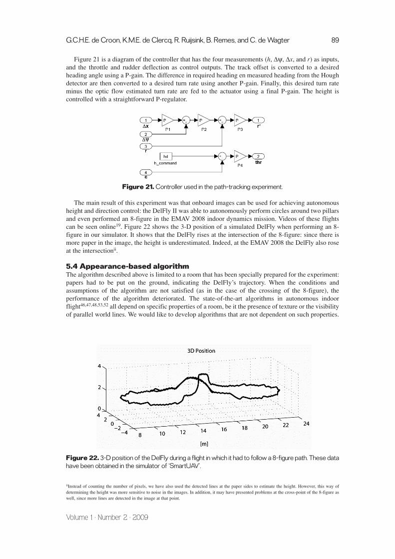
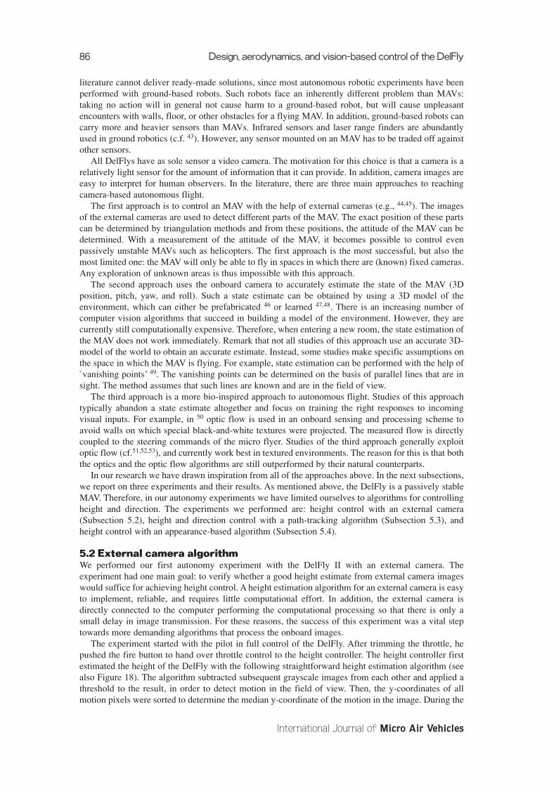
Figure 21 is a diagram of the controller that has the four measurements (h, ∆ψ, ∆x, and r) as inputs,and the throttle and rudder deflection as control outputs. The track offset is converted to a desiredheading angle using a P-gain. The difference in required heading en measured heading from the Houghdetector are then converted to a desired turn rate using another P-gain. Finally, this desired turn rateminus the optic flow estimated turn rate are fed to the actuator using a final P-gain. The height iscontrolled with a straightforward P-regulator.
Figure 21. Controller used in the path-tracking experiment.
The main result of this experiment was that onboard images can be used for achieving autonomousheight and direction control: the DelFly II was able to autonomously perform circles around two pillarsand even performed an 8-figure in the EMAV 2008 indoor dynamics mission. Videos of these flightscan be seen online19. Figure 22 shows the 3-D position of a simulated DelFly when performing an 8-figure in our simulator. It shows that the DelFly rises at the intersection of the 8-figure: since there ismore paper in the image, the height is underestimated. Indeed, at the EMAV 2008 the DelFly also roseat the intersectionii.
5.4 Appearance-based algorithmThe algorithm described above is limited to a room that has been specially prepared for the experiment:papers had to be put on the ground, indicating the DelFly’s trajectory. When the conditions andassumptions of the algorithm are not satisfied (as in the case of the crossing of the 8-figure), theperformance of the algorithm deteriorated. The state-of-the-art algorithms in autonomous indoorflight46,47,48,53,52 all depend on specific properties of a room, be it the presence of texture or the visibilityof parallel world lines. We would like to develop algorithms that are not dependent on such properties.
Figure 22. 3-D position of the DelFly during a flight in which it had to follow a 8-figure path. These datahave been obtained in the simulator of ‘SmartUAV’.
G.C.H.E. de Croon, K.M.E. de Clercq, R. Ruijsink, B. Remes, and C. de Wagter 89
Volume 1 · Number 2 · 2009
iiInstead of counting the number of pixels, we have also used the detected lines at the paper sides to estimate the height. However, this way ofdetermining the height was more sensitive to noise in the images. In addition, it may have presented problems at the cross-point of the 8-figure aswell, since more lines are detected in the image at that point.
As a first step, we discuss a height estimation algorithm that can be applied to any room with enoughspace for the DelFly to fly around. It is an appearance-based vision algorithm with the followingimportant property: the computational effort of the algorithm can be reduced at the cost of a loweraccuracy of the height estimates. The algorithm is based on the philosophy of purposive vision55: thestate of the DelFly is explicitly estimated, but only to the extent necessary for autonomous flight.Hence, the algorithm may be situated in between the second and third approach described in Section5.1. Below, we describe the algorithm and report on the results of our height control experiments withthe DelFly II.
The height estimation algorithm is based on appearance differences between images taken atdifferent heights, assuming little variance in the pitch of the MAV. Simply put: an image taken close tothe ceiling is different from an image taken close to the floor. The algorithm is based on the work ofVarma and Zisserman56. They showed that computationally intensive filtering methods (e.g., Gaborfilters) were outperformed by the computationally efficient texton method on a texture classificationtask.
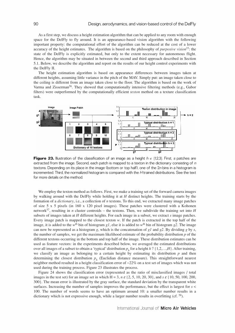
Figure 23. Illustration of the classification of an image as a height h ∈ {1,2,3}. First, s patches areextracted from the image. Second, each patch is mapped to a texton in the dictionary consisting of ntextons. Depending on its place in the image (bottom or top half), one of the 2n bins in a histogram isincremented. Third, the normalized histogram is compared with the H trained distributions. See the textfor more details on the method.
We employ the texton method as follows. First, we make a training set of the forward camera imagesby walking around with the DelFly while holding it at H distinct heights. The training starts by theformation of a dictionary, i.e., a collection of n textons. To this end, we extracted many image patchesof size 5 x 5 pixels (in 160 x 120 pixel images). These patches were clustered with a Kohonennetwork57, resulting in n cluster centroids – the textons. Then, we subdivide the training set into Hsubsets of images taken at H different heights. For each image in a subset, we extract s image patches.Every image patch is mapped to the closest texton w. If the patch is extracted in the top half of theimage, it is added to the wth bin of histogram g1, else it is added to wth bin of histogram g2. The imagecan now be represented as a histogram g, which is the concatenation of g1 and g2. By dividing g by s,the number of samples, we get the maximum likelihood estimate of the probability distribution p of thedifferent textons occurring in the bottom and top half of the image. These distribution estimates can beused as feature vectors: in the experiments described below, we averaged the estimated distributionsover all images of a subset to obtain a ‘typical’ distribution ph for a height h ? {1,2,…,H}. After training,we classify an image as belonging to a certain height by estimating its distribution p and thendetermining the closest distribution ph (Euclidian distance measure). This straightforward nearestneighbor method resulted in a height classification error of ~22% on a test set of images which was notused during the training process. Figure 23 illustrates the process.
Figure 24 shows the classification error (represented as the ratio of misclassified images / totalimages in the test set) for an image set in which H = 3, n ε {2, 5, 10, 20, 30}, and s ε {10, 50, 100, 200,300}. The mean error is illustrated by the gray surface, the standard deviation by the transparent whitesurfaces. Increasing the number of samples improves the performance, but the effect is largest for s <100. The number of words seems to have an optimum around 10: a smaller number results in adictionary which is not expressive enough, while a larger number results in overfitting (cf. 58).
90 Design, aerodynamics, and vision-based control of the DelFly
International Journal of Micro Air Vehicles

Figure 24. Classification error for n ε {2, 5, 10, 20, 30}, and s ε {10, 50, 100, 200, 300}. The mean error isshown with a gray surface, the standard deviation with transparent white surfaces.
For the height control, we used n = 10 words, and H = 5. The height h was linearly scaled to [-1,1],with h = 1 mapped to -1 and h = 5 mapped to 1. h was subsequently processed by a Butterworth filterof order 2 and with a cutoff of 0.305. The resulting value was used as the error value in a P-regulator.
Before executing the height controller, we determined the number of samples that would be used.The left part of Figure 25 shows the relation between the execution frequency of the thread running theheight estimation algorithm in relation to the number of samples. These measurements were done on aDual Core Intel processor at 2.27GHz. Please note that at the time of measurement, the laptop was alsorunning the video capture software, the controller, various output windows, and the communicationwith an RC remote. We decided to use s = 100 samples, to ensure both a reasonable speed and accuracy.
Figure 25. Left: Execution frequency vs. number of samples s. Right: Experiment room.
We tested the height control in an office room that had no other preparation than switching on thelights and pushing the furniture aside (see the right part of Figure 25). After training in the room, theDelFly II successfully maintained a sane height during the experiment; it neither touched the floor norgot close to the ceiling. Since we filmed the DelFly with two external cameras, we were able to estimateits three-dimensional position during the flight. Figure 26 shows the three-dimensional position of theDelFly (left) and the estimated height during the experiment (right). The experiment ended, because thebattery ran out. We hope to perform experiments with new DelFlys soon, in order to test whether it isnecessary to adapt the controller over the battery’s life.
The results presented above are obtained in the room that was also used for training. Of course, forany autonomy of interest, the height control should generalize to other rooms than the training room.We did not test this aspect yet, although it was encouraging that the learned dictionary and distributionswere effective at different times during the day. This means that the method is not too sensitive tolighting conditions. A straightforward option to achieve generalization to different rooms is toconstitute a large training set of images taken in many different office rooms. Another option is toinclude other visual features than appearance alone, such as optic flow. In any case, we have to solvethis matter in order for the algorithm to be useful for achieving full autonomous flight.
G.C.H.E. de Croon, K.M.E. de Clercq, R. Ruijsink, B. Remes, and C. de Wagter 91
Volume 1 · Number 2 · 2009

Figure 26. Left: Three-dimensional position during one of the height control experiments. Right:Corresponding height of the DelFly over time.
6. DELFLY MICRO & BEYOND6.1 DelFly MicroThe research on the DelFly I and DelFly II have led to the successful development of the DelFly Micro:a 3.07 gram weighing ornithopter with a wing span of 10 cm (Figure 27). There are other micro-sizedflying ornithopters59,60. The one described in 59 was inspired on the DelFly Micro and is currently thesmallest flying ornithopter: it has a 6 cm wing span and weighs 1.47g. However, the DelFly Micro isstill the smallest flying ornithopter with a camera and transmitter onboard.
At the small scale of the DelFly Micro it is absolutely necessary to get the maximum out all of itscomponents. The design of the DelFly Micro relies heavily on the advances made on the DelFly I andII concerning the crank mechanism, tail, wing shape, radio control, video system, and insight into theaerodynamics. In addition, advances made on other platforms have been taken into account. Forexample, the 10cm ornithopter in 60 had an additional clap and fling at the middle of the flap. Withoutall the aforementioned advances, the DelFly Micro would most probably not have been able to gainaltitude during its flight. Therefore, we regard the successful flights of the DelFly Micro as ourstrongest argument for a top-down approach. Movies of these flights can be seen online19.
Moreover, having the DelFly I and II allowed us to put in place all necessary elements for autonomyexperiments: ranging from a ground station to the development of vision and control algorithms. Sinceour research on autonomy has focused on a platform with as only sensor a camera, the algorithms thatwe currently test out on the DelFly II can equally be applied to the DelFly Micro. The only hurdle tobe taken in this respect is the flight duration and performance of the DelFly Micro. The current versionof the Micro cannot generate sufficient thrust for hovering, due to overheating of its brushed motors. Acareful reader will notice that similar problems have been experienced with the DelFly I, and that aprobable solution lies in the adoption of an adapted brushless motor. Our main challenge at the momentis to achieve hovering flight of the DelFly Micro.
Total mass 3.07 grBattery 1.00 grCamera and transmitter 0.40 grMotor 0.45 grReceiver 0.20 grActuators 0.50 grRest 0.52 gr
Figure 27. Left: DelFly Micro next to a Euro coin. Right: Mass of the parts.
92 Design, aerodynamics, and vision-based control of the DelFly
International Journal of Micro Air Vehicles

6.2 Challenges AheadWe have stated in the introduction that our long-term goal is to arrive at fly-sized MAVs that can flyautonomously in complex environments. We now discuss the essence of the related challenges and howwe plan to approach them.
First and foremost, the main challenge for achieving a small span size of the ornithopter lies inreducing the weights of all other components. Namely, it is easier to reduce the size of an ornithopterthan to reduce its weight. Reducing an ornithopter’s wing size by two roughly comes down to amultiplication of the wing loading by four, if the weight remains constant. As a consequence, the weightof all components together should be reduced by a factor four – which is generally not possible in thesame time span. Any smaller factor results in a higher wing loading for the new, smaller model. In turn,this signifies that not only should the new components be smaller than the old ones, they should alsoperform better. Better performance is hard to obtain, since at smaller sizes the mechanical, energy, andaerodynamic efficiencies degrade. For example, a smaller drive mechanism has relatively more frictionthan a larger one. This size dilemma is already noticeable at the scale of the DelFly Micro, and is thereason that we feel that some parts of the DelFly should undergo a thorough change in order to enablea DelFly Nano of ~5 cm. One of the candidates for such a change is the drive mechanism. The crank-mechanism actively operates the wing during all phases of the flap. Instead, natural systems andartificial systems of the bottom-up approach2,14 exploit the resonance of the system. Designing aresonant drive mechanism may be a necessary step towards smaller sizes.
Second, at smaller scales, the autonomy of the ornithopter becomes increasingly important. At asmaller size scale the movements of the ornithopter occur at a smaller time scale as well. A reason forthis is the increasingly large mass in relation to the aerodynamic dampening. The smaller size and timescales give more difficulties to a human pilot. The attitude of the ornithopter is more difficult to discernvisually, especially at larger distances. In addition, the movements are harder to predict and the pilotneeds to react quicker. In short, at very small sizes the passive stability properties of the larger DelFlysmay degrade, requiring active stability augmentation. To accommodate this on the long term, we do notonly focus on the size of ornithopters but also on reducing the weight of the existing platforms. Weightreduction allows the addition of sensors and onboard processing. Currently, only a few ultra-lightMAVs have experimented with onboard processing. For example, the work in 50 concerned a 10-grammicro flyer that processed the inputs from a linear pixel-array onboard. It achieved autonomous flightin a textured experiment room. In order to process two-dimensional images, advances have to be madein the above-mentioned weight reduction and in the design of computationally efficient autonomyalgorithms. The algorithm explained in Subsection 5.4 seems a promising candidate for such anonboard processing scheme, if it can generalize over many indoor situations.
Both challenges play a role in the possible application of ornithopters to real-world problems. Anillustration of this was given by the events that occurred at the Technical University of Delft. In May2008, a fire ravaged the building of the faculty of architecture. After the fire was extinguished, thebuilding was in danger of collapsing – preventing the inspection of the inside of the building. Therefore,it was unclear whether some of the precious furniture and book collections inside the building survivedthe fire. Our group offered to make images of the building with a DelFly II. We were able to captureimages of higher floors by looking through the windows. The left part of Figure 28 shows an image ofthe faculty building. We also attempted to enter the building with the DelFly. However, the openings inthe shattered windows were too small and there was too much turbulence around the building. As aconsequence, it was too risky for a human pilot to steer the DelFly into the building. Before the DelFlylanded, it received acknowledgment by nature: it was attacked by a crow, shown in the right part ofFigure 28. We hope that our research on smaller, more autonomous ornithopters might contribute tosimilar tasks in the future – both the exploration of dangerous places and the filming of nature.
G.C.H.E. de Croon, K.M.E. de Clercq, R. Ruijsink, B. Remes, and C. de Wagter 93
Volume 1 · Number 2 · 2009

Figure 28. Left: Image of the faculty building of architecture. Right: Crow attacking the DelFly II (top leftin the image).
ACKNOWLEDGMENTSAs mentioned, the DelFly Project started out as a student assignment, and over the years many peoplehave contributed significantly to the three versions of the DelFly. We are thankful for all of their workand constructive ideas. In particular, we would like to thank D. Lentink - one of the initiators of theproject and a main contributor to the DelFly I and II. Furthermore, we are grateful to the followingpersons: S.R. Jongerius, M.H. Straathof, G.J. van der Veen, W.V.J. Roos, P. Moelans, R.C.A. Lagarde,A.N.A. Kacgor, C.J.G. Heynze, A. Ashok, D.A.J. van Ginneken, N. Bradshaw, and T. Reichert. Inaddition, we are grateful for the interesting discussions with P. Muren, CEO of Proxdynamics. Wewould also like to thank M. van Tooren, H. Bijl, J.A. Mulder, and M.P. Oosten, who have been of agreat support to our efforts. Finally, we would like to thank the board of the TU Delft for granting usaccess to the burnt building of the faculty of architecture.
REFERENCES1 Pornsin-sirirak, T. N., Lee, S. W., Nassef, H., Grasmeyer, J., Tai, Y. C., Ho, C. M., and Keennon,
M. (2000) “MEMS wing technology for a battery-powered ornithopter.” 13th IEEE InternationalConference on Micro Electro Mechanical Systems, (MEMS 2000) , Miyazaki, Japan, Piscataway,NJ, pp. 799-804, 2000.
2 Wood, R.J. “The first takeoff of a biologically-inspired at-scale robotic insect”, IEEE Tranactionson Robotics, Vol. 24, No. 2, pp. 341-347, April, 2008.
3 Michelson, R.C. “Test and Evaluation for Fully Autonomous Micro Air Vehicles”, The ITEAJournal, Volume 29, Number 4, pp. 367 – 374, December, 2008
4 Michelson, R.C. and Naqvi, M.A, “Beyond Biologically-Inspired Insect Flight,” von KarmanInstitute for Fluid Dynamics RTO/AVT Lecture Series on Low Reynolds Number Aerodynamicson Aircraft Including Applications in Emerging UAV Technology, Brussels Belgium, 24-28November, 2003
5 van Breugel, F., Regan W., and Lipson, H. “Passively Stable Flapping Hovering Micro AirVehicle.” International Symposium on Flying Insects and Robotics, pp. 15-16, August, 2007.
6 Boria, F.J., Bachmann, R.J., Ifju, P.G., Quinn, R.D., Vaidyanathan, R., Perry, C., and Wagener, J.(2005) “A Sensor Platform Capable of Aerial and Terrestrial Locomotion”, Intelligent Robots andSystems (IROS), Alberta, Canada, August. 2-6, 2005.
7 Mueller, T. J. and DeLaurier J.D., “Aerodynamics of small vehicles”, Annual Review of FluidMechanics, Volume 35, pp. 89–111, 2003.
8 Keennon M.T. and Grasmeyer J.M., “Development of the Black Widow and Microbat MAVs anda Vision of the Future of MAV Design”, AIAA International Air and Space Symposium andExposition: The Next 100 Years, Dayton, Ohio, July 14-17, 2003
9 Malladi B., Krashanitsa R., Silin D., and Shkarayev S., “Dynamic Model and SystemIdentification Procedure for Autonomous Ornithopter”, Online presentation, The University ofArizona, Tucson, AZ, USA
10 Ansari, S. A., ?bikowski, R., and Knowles, K. “Aerodynamic modelling of insect-like flappingflight for micro air vehicles”, Progress in Aerospace Sciences, Volume 42, Issue 2, pp. 129-172,2006.
94 Design, aerodynamics, and vision-based control of the DelFly
International Journal of Micro Air Vehicles

11 Malolan, V. , Dineshkumar, M., and Baskar, V., “Design and development of flapping wing microair vehicle”, 42nd AIAA Aerospace Sciences Meeting and Exhibit, 5 - 8 January, Reno, Nevada,2004.
12 Ellington, C.P., Berg, C. van den, Willmott, A.P., and Thomas, A.L.R. “Leading-edge vortices ininsect flight” Nature Vol. 384, Issue 19/26, pp. 626-630, 1996.
13 Dickinson, M.H., Lehmann F.-O., and Sane, S.P., “Wing Rotation and the Aerodynamic Basis ofInsect Flight”, Science, Vol. 284. no. 5422, pp. 1954 – 1960, 1999.
14 Steltz, E., Avadhanula, S., and Fearing, R.S., “High Lift Force with 275 Hz Wing Beat in MFI”,IEEE International Conference on Intelligent Robots and Systems, San Diego, October, 2007.
15 Steltz, E. and Fearing, R.S., “Dynamometer Power Output Measurements of PiezoelectricActuators”, IEEE International Conference on Intelligent Robots and Systems, San Diego,October, 2007.
16 Brooks, R. A., “Elephants don’t play chess.”, Robotics and Autonomous Systems, Volume 6,Numbers 1–2, pp. 3–15, 1990.
17 Pfeifer, R. and Scheier, C. “Understanding Intelligence.” MIT Press, Cambridge, MA, 1999.
18 Nolfi, S. and Floreano, D. “Evolutionary Robotics: The Biology, Intelligence, and Technology ofSelf-Organizing Machines.”, MIT Press / Bradford Books, Cambridge, MA, 2000.
19 http://www.delfly.nl/
20 Jongerius S.R., Straathof M.H., van der Veen G.J., Roos W.V.J., Moelans P., Lagarde R.C.A.,Kacgor A.N.A., Heynze C.J.G., Ashok A., de Clercq K.M.E., and van Ginneken D.A.J., “Designof a flapping wing vision-based Micro-UAV”, Design synthesis exercise, Faculty of AerospaceEngineering, TU Delft, 2005.
21 http://www.flyabird.com/ff.html
22 Bradshaw, N.L., and Lentink, D. “Aerodynamic and structural dynamic identification of aflapping wing micro air vehicle”, American Institute of Aeronautics and Astronautics, 26th AIAAApplied Aerodynamics Conference, 2008.
23 Ellington, C.P., “Unsteady aerodynamics of insect flight.” Biological Fluid Dynamics. ed. C.P.Ellington and T.J. Pedley. Symp. Soc. exp. Biol. Volume 49, pp. 109-129, 1995.
24 Anderson, J.D. “Fundamentals of aerodynamics”, Mc Graw-Hill, 2001.
25 Ellington,C.P., “The aerodynamics of hovering insect flight. IV. Aerodynamic mechanisms” Phil.Trans. R. Soc. Lond. B 305, pp. 79-113, 1984.
26 Willmot, P.W., Elington, C.P., Thomas, A.L.R., “Flow visualization and unsteady aerodynamicsin the flight of the hawkmoth, Manduca Sexta” Phil. Trans., 1997.
27 Van den Berg, C., Ellington, C.P., “The three-dimensional leading-edge vortex of a ‘hovering’model hawkmoth” Phil. Trans. R. Soc. Lond. B 352, pp. 329-340, 1997.
28 Maxworthy,T., “Experiments on the Weis-Fogh mechanism of lift generation by insects inhovering flight. Part 1. Dynamics of the ‘fling’” Journal of Fluid Mechanics, vol. 93, part 1,pp.47-63, 1979.
29 Lehmann, F.O., Sane, P.S., Dickinson, M., “The aerodynamic effects of wing-wing interaction inflapping insect wings” Journal of Experimental Biology, Volume 208, pp. 3075-3092, 2005.
30 Poelma, C.; Dickson, W.B.; Dickinson, M.H. “Time-resolved reconstruction of the full velocityfield around a dynamically-scaled flapping wing” Experiments in Fluids Volume 41, pp. 213-225,2006.
31 De Clercq, K.M., de Kat, R., Remes, B., “Flow visualization and force measurements on ahovering flapping-wing MAV ‘DelFly II’”, American Institute of Aeronautics and Astronautics,39th AIAA Applied Aerodynamics Conference (accepted)
32 Ellington, C.P., “The aerodynamics of hovering insect flight. III. Kinematics” Phil. Trans. R. Soc.Lond. B 305, pp. 79-113, 1984.
33 Lehmann, F.O., Pick, S., “The aerodynamic benefit of wing-wing interaction depends on stroketrajectory in flapping insect wings”, Journal of Experimental Biology, Volume 210, pp. 1362-1377, 2007.
34 www.didel.com
G.C.H.E. de Croon, K.M.E. de Clercq, R. Ruijsink, B. Remes, and C. de Wagter 95
Volume 1 · Number 2 · 2009
35 www.microbrushless.com
36 Ma, C.C., Wang, R., Sun, Q.P., Zohar, Y., Wong, M., “Frequency response of TiNi shape memoryalloy thin film micro-actuators”, 13th Annual International Conference on Micro ElectroMechanical Systems (MEMS 2000), pp. 370-374, 2000.
37 www.bsdmicrorc.com
38 Leven, S., Zufferey, J.-C., and Floreano, D., “A Simple and Robust Fixed-Wing Platform forOutdoor Flying Robot Experiments.” International Symposium on Flying Insects and Robots,Monte Verità, Locarno, Switzerland, August 12-17, pp. 69-70, 2007.
39 Kannan, S.K., and Johnson, E.N., “Adaptive Trajectory based Control for AutonomousHelicopters.”, 21st Digital Avionics Systems Conference, Irvine, CA, October, 2002.
40 Johnson, E.N., and Kannan, S.K., “Adaptive Flight Control for an Autonomous UnmannedHelicopter.”, AIAA Guidance, Navigation, and Control Conference and Exhibit, Monterey,California, August, 2002
41 Grzywna, J.W., Plew, J., Nechyba, M.C., and Ifju, P.G., “Enabling Autonomous MAV Flight”,16th Florida Conference on Recent Advances in Robotics, 2003.
42 Elfes, A., Montgomery, J.F., Hall, J.L., Joshi, S.S., Payne, J., and Bergh, C.F., “Autonomous flightcontrol for a Titan exploration aerobot.” 8th International Symposium on Artificial Intelligence,Robotics and Automation in Space (i-SAIRAS 2005), ed. B. Battrick. ESA SP-603. EuropeanSpace Agency, p.91.1, 2005.
43 Thrun, S., Burgard,W., and Fox, D. “Probabilistic Robotics.”, MIT Press, Cambridge, MA, 2005.
44 Mak, L.C., Whitty, M., Furukawa, T., “A localisation system for an indoor rotary-wing MAVusing blade mounted LEDs.”, Sensor Review, Volume 28, Number 2, pp. 125-131, 2008.
45 Rudol, P., Wzorek, M., Conte, G., and Doherty, P., “Micro Unmanned Aerial Vehicle VisualServoing for Cooperative Indoor Exploration.”, Proceedings of the 2008 IEEE AerospaceConference, 2008.
46 Kemp, C., “Visual Control of a Quad-Rotor Helicopter.”, Ph.D. Thesis, Churchill College,University of Cambridge, 2006.
47 Elik, K.C., Chung, S.-J., and Somani, A., “Mono-Vision Corner SLAM for Indoor Navigation.”,IEEE International Conference on Electro/Information Technology 2008, pp. 343-348, 2008.
48 Ahrens S., “Vision-Based Guidance and Control of a Hovering Vehicle in UnknownEnvironments”, M.Sc. Thesis, MIT SM, June, 2008.
49 Johnson N., “Vision-assisted control of a hovering air vehicle in an indoor setting”, M.Sc. thesis,Brigham Young University, 2008.
50 Zufferey, J.-C., Klaptocz, A., Beyeler, A., Nicoud, J.-D., and Floreano, D., “A 10-gram Microflyerfor Vision-based Indoor Navigation”, Proceedings of the 2006 IEEE/RSJ InternationalConference on Intelligent Robots and Systems October 9 - 15, Beijing, China, 2006.
51 Iida, F., “Goal-directed navigation of an autonomous flying robot using biologically inspiredcheap vision.”, Proceedings of the 32nd ISR (International Symposium on Robotics), 2001.
52 Humbert, J.S., and Frye, M.A., “Extracting behaviorally relevant retinal image motion cues viawide-field integration.” American Control Conference, number 14–16, pp. 6, 2006
53 Beyeler, A., Zufferey, J-C., and Floreano, D. “3d vision-based navigation for indoormicroflyers.”, IEEE International Conference on Robotics and Automation 2007, Roma, Italy, pp.1336–1341, 2007
54 Open CV: http://sourceforge.net/projects/opencvlibrary/
55 Aloimonos, J., “Purposive and qualitative active vision.”, 10th International Conference onPattern Recognition, volume 1, pp. 346–360, Atlantic City, NJ, 1990.
56 Varma M., and Zisserman. A., “Texture classification: are filter banks necessary?” IEEEComputer Society Conference on Computer Vision and Pattern Recognition (CVPR 2003),Madison, WI, volume 2, pp. 691–698. IEEE Computer Society, 2003.
57 Kohonen, T., “Self-Organizing Maps”, 3rd edition, Springer Series in Information Sciences, Vol.30. Springer, 2001.
96 Design, aerodynamics, and vision-based control of the DelFly
International Journal of Micro Air Vehicles
58 Bishop, C.M., “Pattern recognition and machine learning.” Springer Science and Business Media,LLC, New York, NY, 2006.
59 Takahashi, Y. Blog: http://blog.goo.ne.jp/flappingwing/e/722e1073f96aaccd8892ea63f8240ded,Movie: http://www.youtube.com/watch?v=zo-69d5AF-o
60 Satoshi, S., and Yoshiyuki, K. “Development of a Flapping Micro Air Vehicle With HoveringAbility.”, Nihon Kikai Gakkai Ryutai Kogaku Bumon Koenkai Koen Ronbunshu
G.C.H.E. de Croon, K.M.E. de Clercq, R. Ruijsink, B. Remes, and C. de Wagter 97
Volume 1 · Number 2 · 2009
