description & operation - · pdf fileair bag restraint system mazda 1990-91 air bags...
TRANSCRIPT
AIR BAG RESTRAINT SYSTEM
MAZDA 1990-91 AIR BAGS
DESCRIPTION & OPERATION
The air bag restraint system, when used in conjunction with seat belt, provides increased protection for the driver in a collision. The air bag restraint system consists of the following: AIR BAG warning light, air bag module, clockspring connector, diagnostic module, crash sensors, back-up battery, and wiring harnesses.
The air bag is designed to deploy when rear safing sensor and at least one front impact sensor close in a collision, and ignition switch is in the ON position. The back-up battery supplies current for the ignitor if the vehicle battery or fuses fail during a collision. The diagnostic module monitors the air bag system for failures. If any failures are detected by the module, the driver is warned of such failure(s) through the activation or flashing of the AIR BAG warning light.
SERVICE PRECAUTIONS
Disable air bag system before servicing any air bag system or steering column component. See DISABLING & ACTIVATING AIR BAG SYSTEM
Wait about 10 MINUTES after disabling air bag system before servicing. Air bag system voltage is maintained for about 10 MINUTES after system is disabled. Failure to wait 10 MINUTES before servicing system may cause accidental air bag deployment and possible personal injury.
On Miata, obtain radio code number from customer and deactivate radio anti-theft function before disconnecting battery.
Because of the critical system operating requirements, DO NOT service any air bag system component. Corrections are made by replacement only.
DO NOT use an ohmmeter to check resistance of air bag module, as it may cause air bag deployment.
When carrying a live (undeployed) module, ensure trim cover is pointed away from your body. This minimizes chance of injure in the event ofaccidental air bag deployment.
When placing a live air bag module on any surface, always face trim cover upward to reduce motion of module if it is accidentally deployed.
If an open circuit is present, replace entire wiring harness. DO NOT attempt wire repair.
Impact sensors must always be installed with arrow marks facing front of vehicle. Also, check sensors for cracks, defects or rust before installation. Replace impact sensor(s) if required.
Air bag system clockspring MUST be aligned in the neutral position, since its rotation ability is limited. DO NOT turn steering wheel or column after removal of steering gear.
WARNING: To avoid injury from accidental air bag deployment, read and carefully follow all WARNINGS and SERVICE PRECAUTIONS.
NOTE: The following precautions should be observed when working with air bag systems.
1991 Mazda MX-5 Miata
AIR BAG RESTRAINT SYSTEM MAZDA 1990-91 AIR BAGS
1991 Mazda MX-5 Miata
AIR BAG RESTRAINT SYSTEM MAZDA 1990-91 AIR BAGS
Microsoft
Sunday, July 05, 2009 2:11:16 PM Page 1 © 2005 Mitchell Repair Information Company, LLC.
Microsoft
Sunday, July 05, 2009 2:11:26 PM Page 1 © 2005 Mitchell Repair Information Company, LLC.
A double-lock mechanism is used on clockspring connectors. DO NOT use excessive force when disconnecting connectors, as damage to connector may occur.
DISABLING & ACTIVATING AIR BAG SYSTEM
AIR BAG SYSTEM
DISABLING SYSTEM
On Miata, obtain radio code number from customer, and deactivate audio anti-theft function. On all models, turn ignition switch off. Disconnect and shield negative battery cable. Remove knee protector. Disconnect Orange and Blue clockspring connectors at base of steering column. See Fig. 1 .
ACTIVATING SYSTEM
Reconnect battery and clockspring connectors. Turn ignition switch to RUN position. Check AIR BAG indicator light to ensure system is operating properly. See SYSTEM OPERATION CHECK.
WARNING: Wait about 10 MINUTES after disabling air bag system before servicing. Air bag system voltage is maintained for about 10 MINUTES after system is disabled. Failure to wait 10 MINUTES before servicing system may cause accidental air bag deployment and possible personal injury.
1991 Mazda MX-5 Miata
AIR BAG RESTRAINT SYSTEM MAZDA 1990-91 AIR BAGS
Microsoft
Sunday, July 05, 2009 2:11:16 PM Page 2 © 2005 Mitchell Repair Information Company, LLC.

Fig. 1: Locating Clockspring Connector Courtesy of MAZDA MOTORS CORP.
POST-COLLISION AIR BAG SAFETY INSPECTION
POST-COLLISION AIR BAG SAFETY INSPECTION Replace After Deployment Air Bag Module(s)
Clockspring Inspect & If Damaged, Replace Component (Even If Air Bag Did Not Deploy)
Air Bag Diagnosis Control Unit
Impact Sensors & Sensors Mountings
Steering Column
Steering Wheel
Wiring Harness Comments DO NOT attempt wiring harness repairs.
Replace entire wiring harness.
Impact sensors must always be installed with arrow on sensor facing front of vehicle.
1991 Mazda MX-5 Miata
AIR BAG RESTRAINT SYSTEM MAZDA 1990-91 AIR BAGS
Microsoft
Sunday, July 05, 2009 2:11:16 PM Page 3 © 2005 Mitchell Repair Information Company, LLC.
ADJUSTMENTS
CLOCKSPRING CENTERING
Set front wheels in straight-ahead position. Turn clockspring connector clockwise until it stops (do not force). Return connector 2 3/4 turns counterclockwise. Rotate clockspring connector further, if necessary, to align marks on connector and outer housing.
DISPOSAL PROCEDURES
DEPLOYED AIR BAG
Dispose deployed air bag module as you would any other part. Wear gloves and safety glasses when handling air bag module.
SCRAPPED VEHICLE
1. Ensure vehicle is outside, and away from other vehicles and people. Open convertible top and doors. Disconnect negative battery cable.
2. Ensure air bag module is firmly mounted to steering wheel. Remove knee protector and disconnect Orange and Blue clockspring connectors at base of steering column. See Fig. 1 . Cut clockspring connector Blue wires.
3. Connect 2 jumper wires (20 feet long) to cut clockspring wires. Connect other ends of wires to a 12-volt battery to deploy air bag. Because of heat, wait 10 MINUTES before touching deployed air bag.
REMOVAL & INSTALLATION
CRASH SENSORS
NOTE: Perform the following procedures when scrapping a vehicle with undeployed air bag.
WARNING: Follow air bag service precautions to prevent accidentalair bag deployment and personal injury. See SERVICE PRECAUTIONS.
NOTE: After component replacement, check system to ensure proper operation. See SYSTEM OPERATION CHECK.
NOTE: Crash sensor orientation and mounting is important for proper operation. All sensors must be positioned so that arrow points forward. If there is sheet metal damage near sensor mounting point, inspect body structure at sensor mounting point for deformation. If damaged, restore to original shape. Ensure sensor mounting bolts or nuts are tightened to specification. See TORQUE SPECIFICATIONS table.
1991 Mazda MX-5 Miata
AIR BAG RESTRAINT SYSTEM MAZDA 1990-91 AIR BAGS
Microsoft
Sunday, July 05, 2009 2:11:16 PM Page 4 © 2005 Mitchell Repair Information Company, LLC.
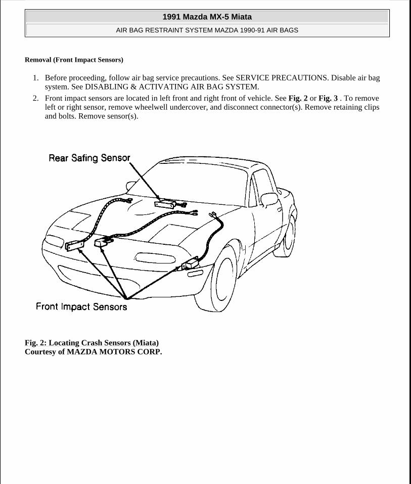
Removal (Front Impact Sensors)
1. Before proceeding, follow air bag service precautions. See SERVICE PRECAUTIONS. Disable air bag system. See DISABLING & ACTIVATING AIR BAG SYSTEM.
2. Front impact sensors are located in left front and right front of vehicle. See Fig. 2 or Fig. 3 . To remove left or right sensor, remove wheelwell undercover, and disconnect connector(s). Remove retaining clips and bolts. Remove sensor(s).
Fig. 2: Locating Crash Sensors (Miata) Courtesy of MAZDA MOTORS CORP.
1991 Mazda MX-5 Miata
AIR BAG RESTRAINT SYSTEM MAZDA 1990-91 AIR BAGS
Microsoft
Sunday, July 05, 2009 2:11:16 PM Page 5 © 2005 Mitchell Repair Information Company, LLC.
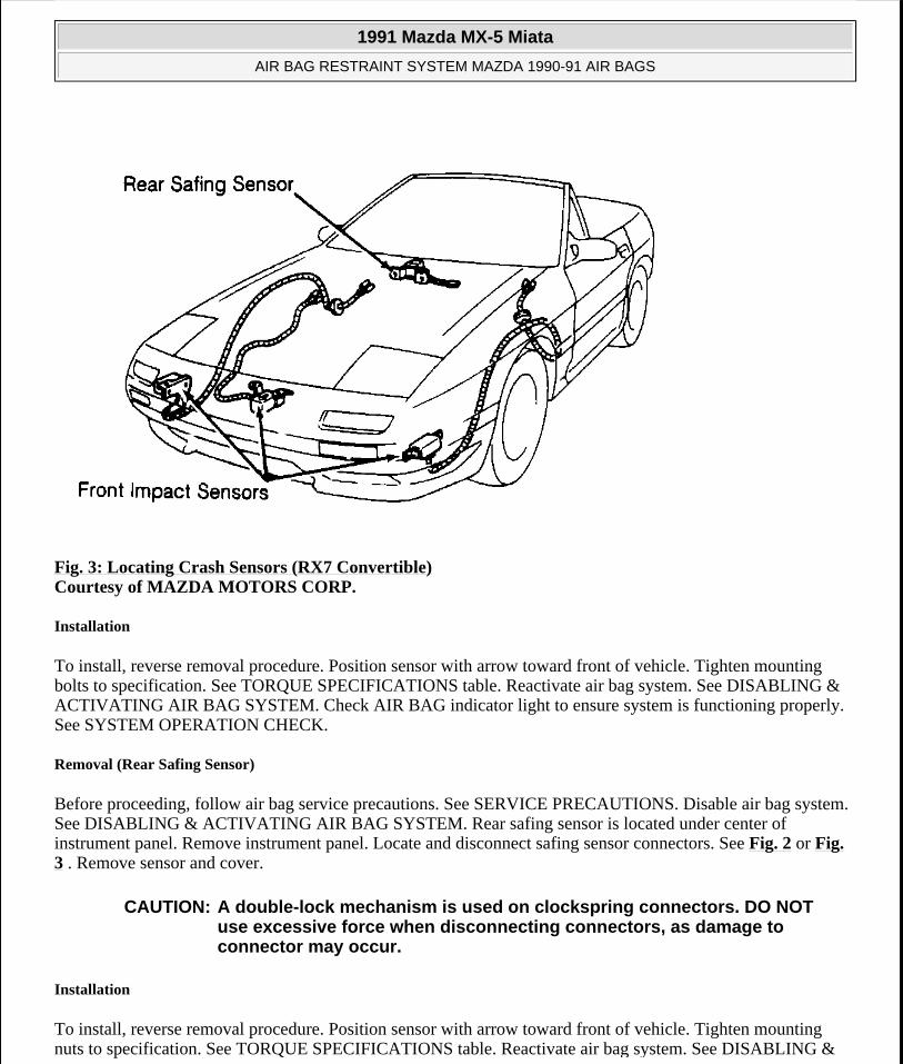
Fig. 3: Locating Crash Sensors (RX7 Convertible) Courtesy of MAZDA MOTORS CORP.
Installation
To install, reverse removal procedure. Position sensor with arrow toward front of vehicle. Tighten mounting bolts to specification. See TORQUE SPECIFICATIONS table. Reactivate air bag system. See DISABLING & ACTIVATING AIR BAG SYSTEM. Check AIR BAG indicator light to ensure system is functioning properly. See SYSTEM OPERATION CHECK.
Removal (Rear Safing Sensor)
Before proceeding, follow air bag service precautions. See SERVICE PRECAUTIONS. Disable air bag system. See DISABLING & ACTIVATING AIR BAG SYSTEM. Rear safing sensor is located under center of instrument panel. Remove instrument panel. Locate and disconnect safing sensor connectors. See Fig. 2 or Fig. 3 . Remove sensor and cover.
Installation
To install, reverse removal procedure. Position sensor with arrow toward front of vehicle. Tighten mounting nuts to specification. See TORQUE SPECIFICATIONS table. Reactivate air bag system. See DISABLING &
CAUTION: A double-lock mechanism is used on clockspring connectors. DO NOT use excessive force when disconnecting connectors, as damage to connector may occur.
1991 Mazda MX-5 Miata
AIR BAG RESTRAINT SYSTEM MAZDA 1990-91 AIR BAGS
Microsoft
Sunday, July 05, 2009 2:11:16 PM Page 6 © 2005 Mitchell Repair Information Company, LLC.
ACTIVATING AIR BAG SYSTEM. Check AIR BAG indicator light to ensure system is functioning properly. See SYSTEM OPERATION CHECK.
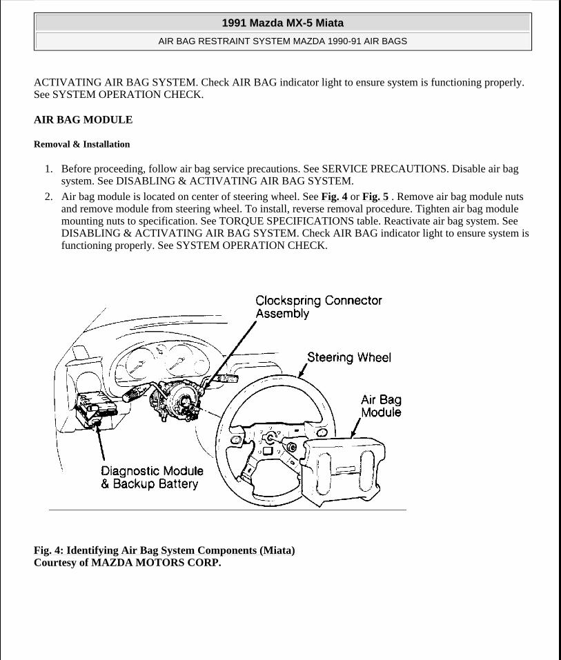
AIR BAG MODULE
Removal & Installation
1. Before proceeding, follow air bag service precautions. See SERVICE PRECAUTIONS. Disable air bag system. See DISABLING & ACTIVATING AIR BAG SYSTEM.
2. Air bag module is located on center of steering wheel. See Fig. 4 or Fig. 5 . Remove air bag module nuts and remove module from steering wheel. To install, reverse removal procedure. Tighten air bag module mounting nuts to specification. See TORQUE SPECIFICATIONS table. Reactivate air bag system. See DISABLING & ACTIVATING AIR BAG SYSTEM. Check AIR BAG indicator light to ensure system is functioning properly. See SYSTEM OPERATION CHECK.
Fig. 4: Identifying Air Bag System Components (Miata) Courtesy of MAZDA MOTORS CORP.
1991 Mazda MX-5 Miata
AIR BAG RESTRAINT SYSTEM MAZDA 1990-91 AIR BAGS
Microsoft
Sunday, July 05, 2009 2:11:16 PM Page 7 © 2005 Mitchell Repair Information Company, LLC.
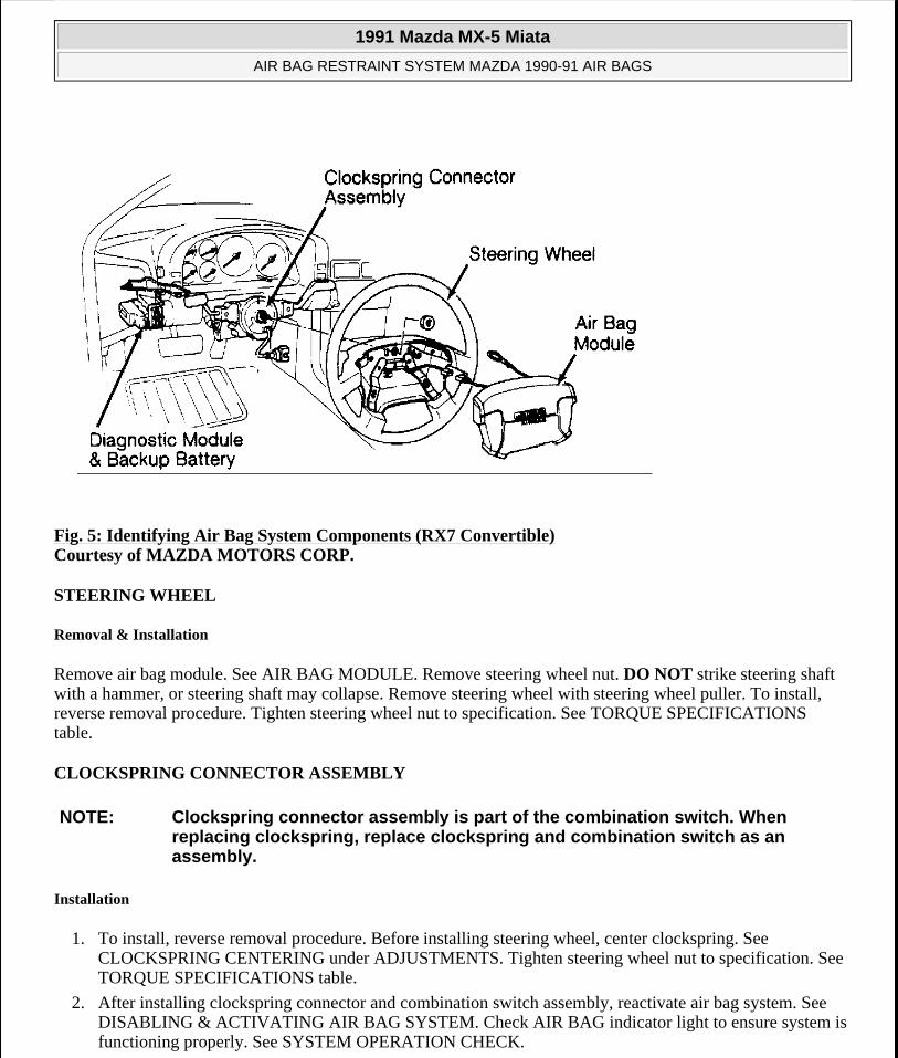
Fig. 5: Identifying Air Bag System Components (RX7 Convertible) Courtesy of MAZDA MOTORS CORP.
STEERING WHEEL
Removal & Installation
Remove air bag module. See AIR BAG MODULE. Remove steering wheel nut. DO NOT strike steering shaft with a hammer, or steering shaft may collapse. Remove steering wheel with steering wheel puller. To install, reverse removal procedure. Tighten steering wheel nut to specification. See TORQUE SPECIFICATIONS table.
CLOCKSPRING CONNECTOR ASSEMBLY
Installation
1. To install, reverse removal procedure. Before installing steering wheel, center clockspring. See CLOCKSPRING CENTERING under ADJUSTMENTS. Tighten steering wheel nut to specification. See TORQUE SPECIFICATIONS table.
2. After installing clockspring connector and combination switch assembly, reactivate air bag system. See DISABLING & ACTIVATING AIR BAG SYSTEM. Check AIR BAG indicator light to ensure system is functioning properly. See SYSTEM OPERATION CHECK.
NOTE: Clockspring connector assembly is part of the combination switch. When replacing clockspring, replace clockspring and combination switch as an assembly.
1991 Mazda MX-5 Miata
AIR BAG RESTRAINT SYSTEM MAZDA 1990-91 AIR BAGS
Microsoft
Sunday, July 05, 2009 2:11:16 PM Page 8 © 2005 Mitchell Repair Information Company, LLC.
Removal
1. Before proceeding, follow air bag service precautions. See SERVICE PRECAUTIONS. Disable air bag system. See DISABLING & ACTIVATING AIR BAG SYSTEM.
2. Clockspring connector assembly is located under steering wheel, in steering column. See Fig. 4 or Fig. 5 . Remove air bag module. See AIR BAG MODULE. Remove steering wheel nut and remove steering wheel with steering wheel puller. Remove column covers. Remove screws. Remove clockspring connector and combination switch as an assembly.
DIAGNOSTIC MODULE & BACK-UP BATTERY
Removal & Installation
1. Before proceeding, follow air bag service precautions. See SERVICE PRECAUTIONS. Disable air bag system. See DISABLING & ACTIVATING AIR BAG SYSTEM.
2. Diagnostic module and back-up battery is located under left side of instrument panel. See Fig. 4 or Fig. 5 . Disconnect diagnostic module and back-up battery connectors. Remove nuts. Remove diagnostic module and back-up battery as an assembly. To install, reverse removal procedure. After diagnostic module and back-up battery are installed, reactivate air bag system. See DISABLING & ACTIVATING AIR BAG SYSTEM. Check AIR BAG indicator light to ensure system is functioning properly. See SYSTEM OPERATION CHECK.
SYSTEM OPERATION CHECK
Turn ignition switch to the ON or START position. AIR BAG warning light in instrument cluster should illuminate for approximately 6 seconds then go out. This indicates that the air bag system is functioning properly. If any of the following conditions exists, air bag system is malfunctioning and needs repair.
AIR BAG warning light does not illuminate as described.
AIR BAG warning light stays on for more than 6 seconds.
AIR BAG warning light illuminates while driving.
If air bag system components are replaced for any reason, air bag system must be checked for proper function after repair. Turn ignition on. AIR BAG warning light should illuminate for approximately 6 seconds then go out. If AIR BAG warning light does not illuminate as described, air bag system is malfunctioning and needs repair. If warning light functions as described, check horn operation. If horn does not sound, remove air bag module and check air bag module and horn switch connections. Always follow service precautions and deactivate air bag system before performing repairs. See DISABLING & ACTIVATING AIR BAG SYSTEM .
WIRE REPAIR
DO NOT repair air bag system wiring. If air bag harness connectors are faulty, replace faulty wiring harness.
TORQUE SPECIFICATIONS
1991 Mazda MX-5 Miata
AIR BAG RESTRAINT SYSTEM MAZDA 1990-91 AIR BAGS
Microsoft
Sunday, July 05, 2009 2:11:16 PM Page 9 © 2005 Mitchell Repair Information Company, LLC.
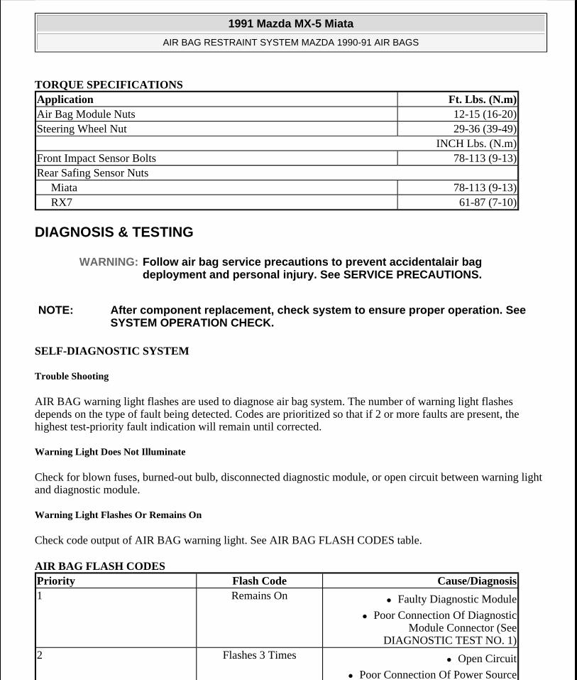
TORQUE SPECIFICATIONS
DIAGNOSIS & TESTING
SELF-DIAGNOSTIC SYSTEM
Trouble Shooting
AIR BAG warning light flashes are used to diagnose air bag system. The number of warning light flashes depends on the type of fault being detected. Codes are prioritized so that if 2 or more faults are present, the highest test-priority fault indication will remain until corrected.
Warning Light Does Not Illuminate
Check for blown fuses, burned-out bulb, disconnected diagnostic module, or open circuit between warning light and diagnostic module.
Warning Light Flashes Or Remains On
Check code output of AIR BAG warning light. See AIR BAG FLASH CODES table.
AIR BAG FLASH CODES
Application Ft. Lbs. (N.m)Air Bag Module Nuts 12-15 (16-20)Steering Wheel Nut 29-36 (39-49)
INCH Lbs. (N.m)Front Impact Sensor Bolts 78-113 (9-13)Rear Safing Sensor Nuts
Miata 78-113 (9-13)RX7 61-87 (7-10)
WARNING: Follow air bag service precautions to prevent accidentalair bag deployment and personal injury. See SERVICE PRECAUTIONS.
NOTE: After component replacement, check system to ensure proper operation. See SYSTEM OPERATION CHECK.
Priority Flash Code Cause/Diagnosis1 Remains On Faulty Diagnostic Module
Poor Connection Of Diagnostic Module Connector (See
DIAGNOSTIC TEST NO. 1) 2 Flashes 3 Times Open Circuit
Poor Connection Of Power Source
1991 Mazda MX-5 Miata
AIR BAG RESTRAINT SYSTEM MAZDA 1990-91 AIR BAGS
Microsoft
Sunday, July 05, 2009 2:11:16 PM Page 10 © 2005 Mitchell Repair Information Company, LLC.
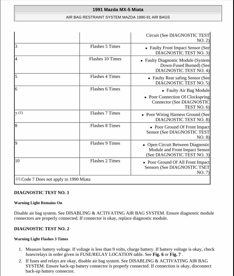
DIAGNOSTIC TEST NO. 1
Warning Light Remains On
Disable air bag system. See DISABLING & ACTIVATING AIR BAG SYSTEM. Ensure diagnostic module connectors are properly connected. If connector is okay, replace diagnostic module.
DIAGNOSTIC TEST NO. 2
Warning Light Flashes 3 Times
1. Measure battery voltage. If voltage is less than 9 volts, charge battery. If battery voltage is okay, check fuses/relays in order given in FUSE/RELAY LOCATION table. See Fig. 6 or Fig. 7 .
2. If fuses and relays are okay, disable air bag system. See DISABLING & ACTIVATING AIR BAG SYSTEM. Ensure back-up battery connector is properly connected. If connection is okay, disconnect back-up battery connector.
Circuit (See DIAGNOSTIC TEST NO. 2)
3 Flashes 5 Times Faulty Front Impact Sensor (See DIAGNOSTIC TEST NO. 3)
4 Flashes 10 Times Faulty Diagnostic Module (System Down-Fused Burned) (See
DIAGNOSTIC TEST NO. 4) 5 Flashes 4 Times Faulty Rear safing Sensor (See
DIAGNOSTIC TEST NO. 5) 6 Flashes 6 Times Faulty Air Bag Module
Poor Connection Of Clockspring Connector (See DIAGNOSTIC
TEST NO. 6)
7 (1) Flashes 7 Times Poor Wiring Harness Ground (See DIAGNOSTIC TEST NO. 8)
8 Flashes 8 Times Poor Ground Of Front Impact Sensor (See DIAGNOSTIC TEST
NO. 8) 9 Flashes 9 Times Open Circuit Between Diagnostic
Module and Front Impact Sensor (See DIAGNOSTIC TEST NO. 3)
10 Flashes 2 Times Poor Ground Of All Front Impact Sensors (See DIAGNOSTIC TSET
NO. 7) (1) Code 7 Does not apply to 1990 Miata
1991 Mazda MX-5 Miata
AIR BAG RESTRAINT SYSTEM MAZDA 1990-91 AIR BAGS
Microsoft
Sunday, July 05, 2009 2:11:16 PM Page 11 © 2005 Mitchell Repair Information Company, LLC.
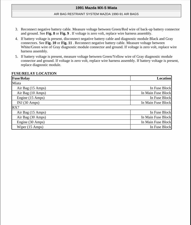
3. Reconnect negative battery cable. Measure voltage between Green/Red wire of back-up battery connector and ground. See Fig. 8 or Fig. 9 . If voltage is zero volt, replace wire harness assembly.
4. If battery voltage is present, disconnect negative battery cable and diagnostic module Black and Gray connectors. See Fig. 10 or Fig. 11 . Reconnect negative battery cable. Measure voltage between White/Green wire of Gray diagnostic module connector and ground. If voltage is zero volt, replace wire harness assembly.
5. If battery voltage is present, measure voltage between Green/Yellow wire of Gray diagnostic module connector and ground. If voltage is zero volt, replace wire harness assembly. If battery voltage is present, replace diagnostic module.
FUSE/RELAY LOCATION Fuse/Relay LocationMiata
Air Bag (15 Amps) In Fuse BlockAir Bag (10 Amps) In Main Fuse BlockEngine (15 Amps) In Fuse BlockINJ (30 Amps) In Main Fuse Block
RX7Air Bag (15 Amps) In Fuse BlockAir Bag (30 Amps) In Main Fuse BlockEngine (30 Amps) In Main Fuse BlockWiper (15 Amps) In Fuse Block
1991 Mazda MX-5 Miata
AIR BAG RESTRAINT SYSTEM MAZDA 1990-91 AIR BAGS
Microsoft
Sunday, July 05, 2009 2:11:16 PM Page 12 © 2005 Mitchell Repair Information Company, LLC.
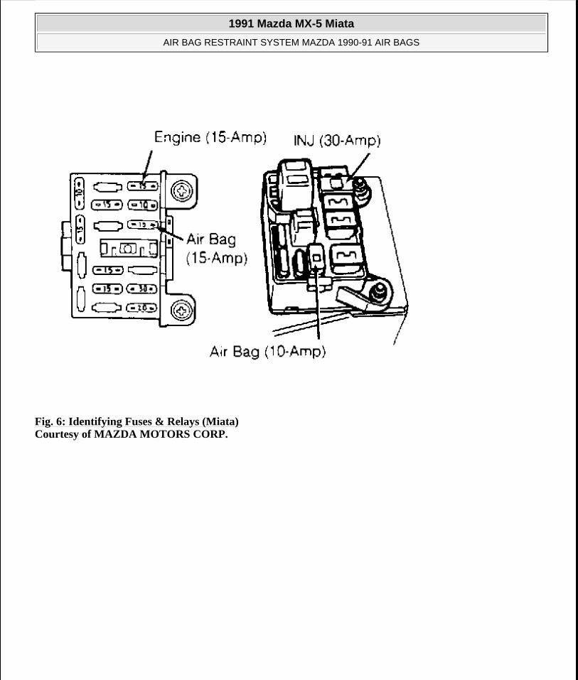
Fig. 6: Identifying Fuses & Relays (Miata) Courtesy of MAZDA MOTORS CORP.
1991 Mazda MX-5 Miata
AIR BAG RESTRAINT SYSTEM MAZDA 1990-91 AIR BAGS
Microsoft
Sunday, July 05, 2009 2:11:16 PM Page 13 © 2005 Mitchell Repair Information Company, LLC.
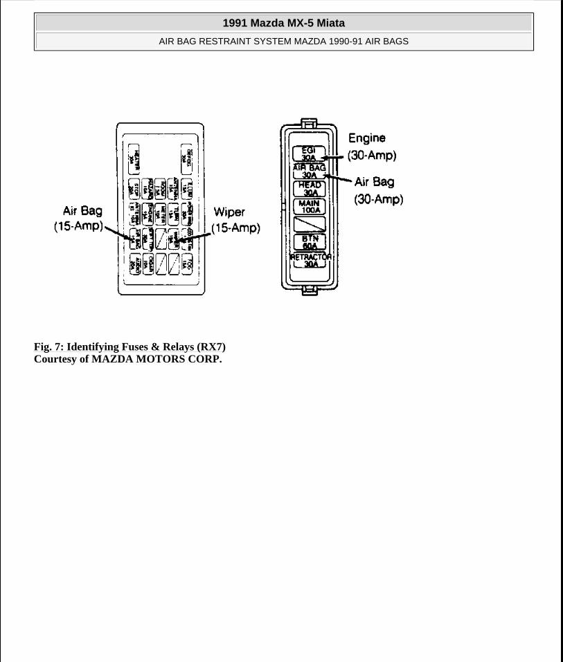
Fig. 7: Identifying Fuses & Relays (RX7) Courtesy of MAZDA MOTORS CORP.
1991 Mazda MX-5 Miata
AIR BAG RESTRAINT SYSTEM MAZDA 1990-91 AIR BAGS
Microsoft
Sunday, July 05, 2009 2:11:16 PM Page 14 © 2005 Mitchell Repair Information Company, LLC.
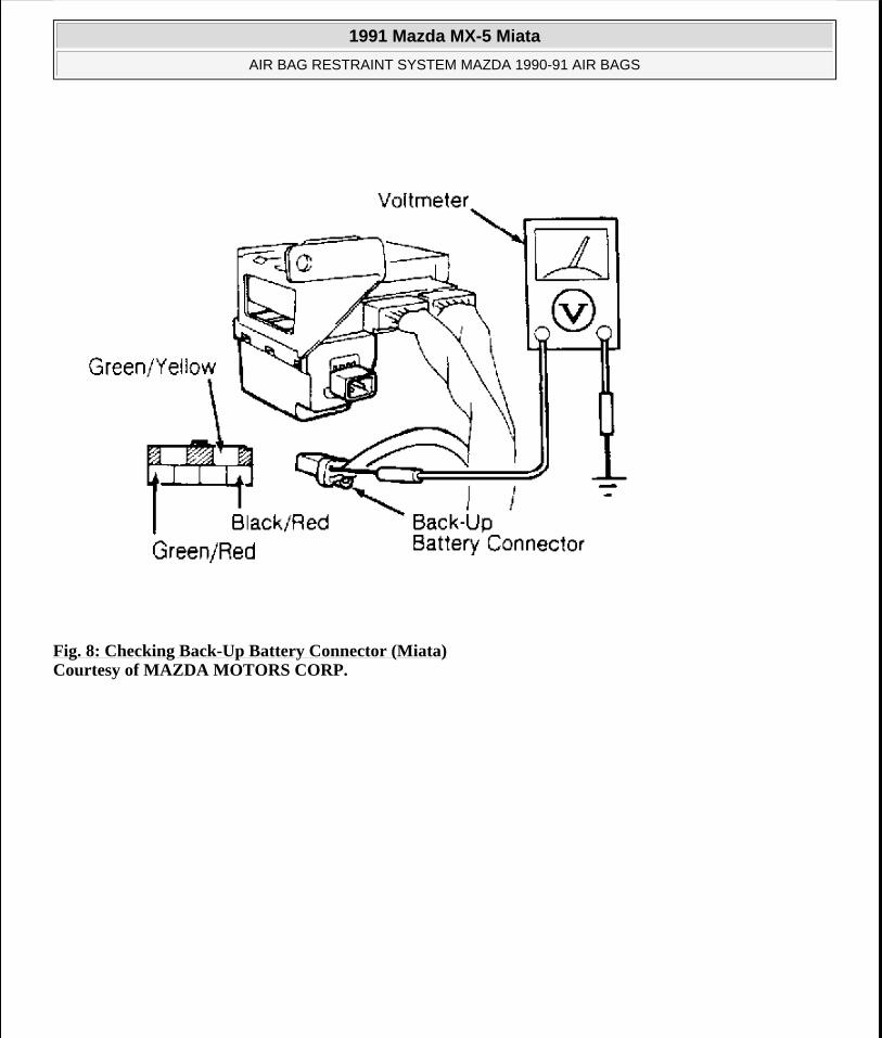
Fig. 8: Checking Back-Up Battery Connector (Miata) Courtesy of MAZDA MOTORS CORP.
1991 Mazda MX-5 Miata
AIR BAG RESTRAINT SYSTEM MAZDA 1990-91 AIR BAGS
Microsoft
Sunday, July 05, 2009 2:11:16 PM Page 15 © 2005 Mitchell Repair Information Company, LLC.
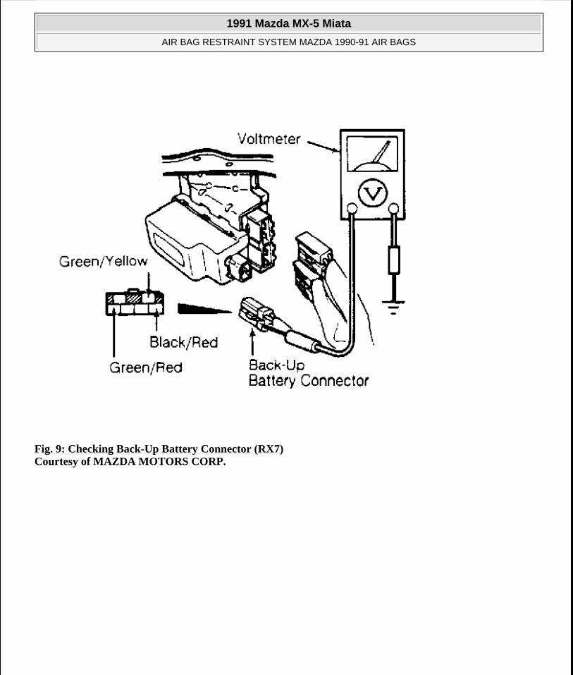
Fig. 9: Checking Back-Up Battery Connector (RX7) Courtesy of MAZDA MOTORS CORP.
1991 Mazda MX-5 Miata
AIR BAG RESTRAINT SYSTEM MAZDA 1990-91 AIR BAGS
Microsoft
Sunday, July 05, 2009 2:11:16 PM Page 16 © 2005 Mitchell Repair Information Company, LLC.
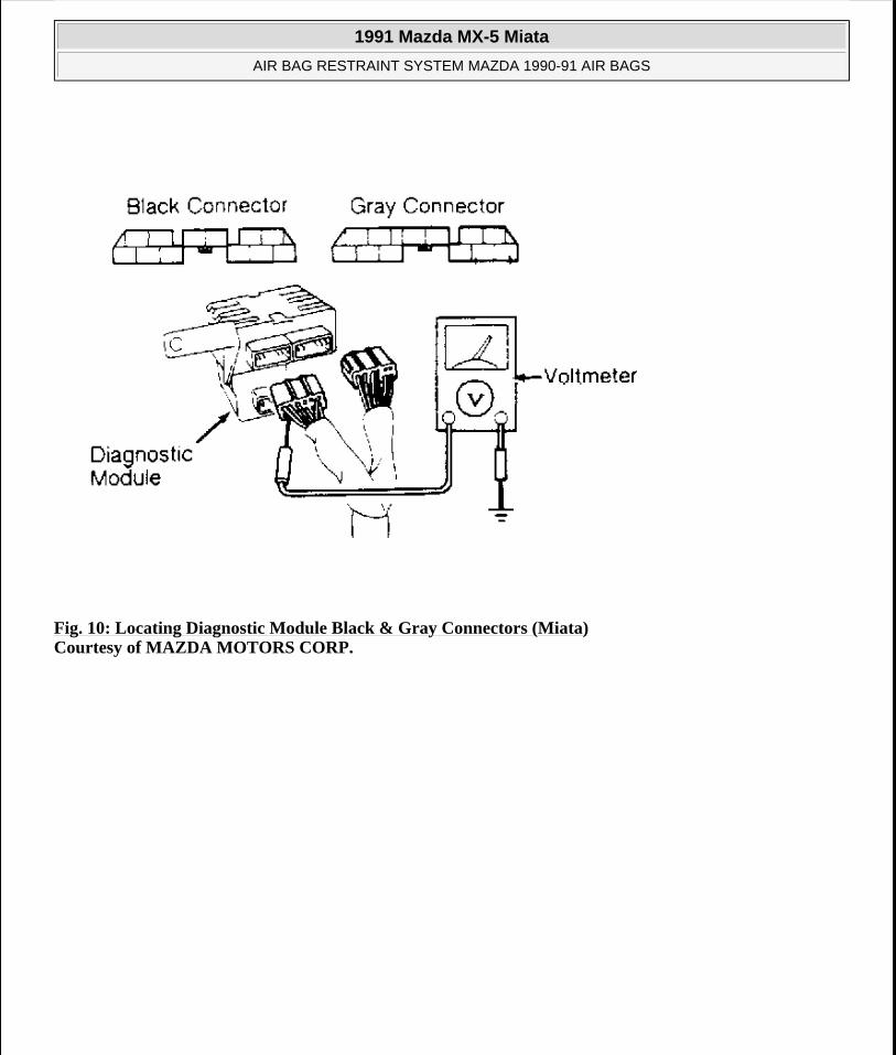
Fig. 10: Locating Diagnostic Module Black & Gray Connectors (Miata) Courtesy of MAZDA MOTORS CORP.
1991 Mazda MX-5 Miata
AIR BAG RESTRAINT SYSTEM MAZDA 1990-91 AIR BAGS
Microsoft
Sunday, July 05, 2009 2:11:16 PM Page 17 © 2005 Mitchell Repair Information Company, LLC.

Fig. 11: Locating Diagnostic Module Black & Gray Connectors (RX7) Courtesy of MAZDA MOTORS CORP.
DIAGNOSTIC TEST NO. 3
Warning Light Flashes 5 Or 9 Times
1. Disable air bag system. See DISABLING & ACTIVATING AIR BAG SYSTEM. Disconnect front impact sensor connectors (center, left, and right), and measure resistance of each sensor. See Fig. 12 . Resistance should be approximately 1.2 k/ohms. If resistance is not as specified, replace sensor.
2. If resistance is about 1.2 k/ohms, reconnect all front impact sensor connectors. Disconnect diagnostic module Black and Gray connectors. See Fig. 10 or Fig. 11 . Measure resistance between diagnostic module Gray connector Brown/Green wire and ground. If resistance is 1.2 k/ohms, go to next step. If resistance is not 1.2 k/ohms, replace wire harness.
3. Measure resistance between diagnostic module Gray connector Brown/Red wire and ground. If resistance is 1.2 k/ohms, go to next step. If resistance is not 1.2 k/ohms, replace wire harness.
4. Measure resistance between diagnostic module Black connector Brown/Black wire and ground. If resistance is 1.2 k/ohms, replace diagnostic module. If resistance is not 1.2 k/ohms, replace wire harness.
1991 Mazda MX-5 Miata
AIR BAG RESTRAINT SYSTEM MAZDA 1990-91 AIR BAGS
Microsoft
Sunday, July 05, 2009 2:11:16 PM Page 18 © 2005 Mitchell Repair Information Company, LLC.
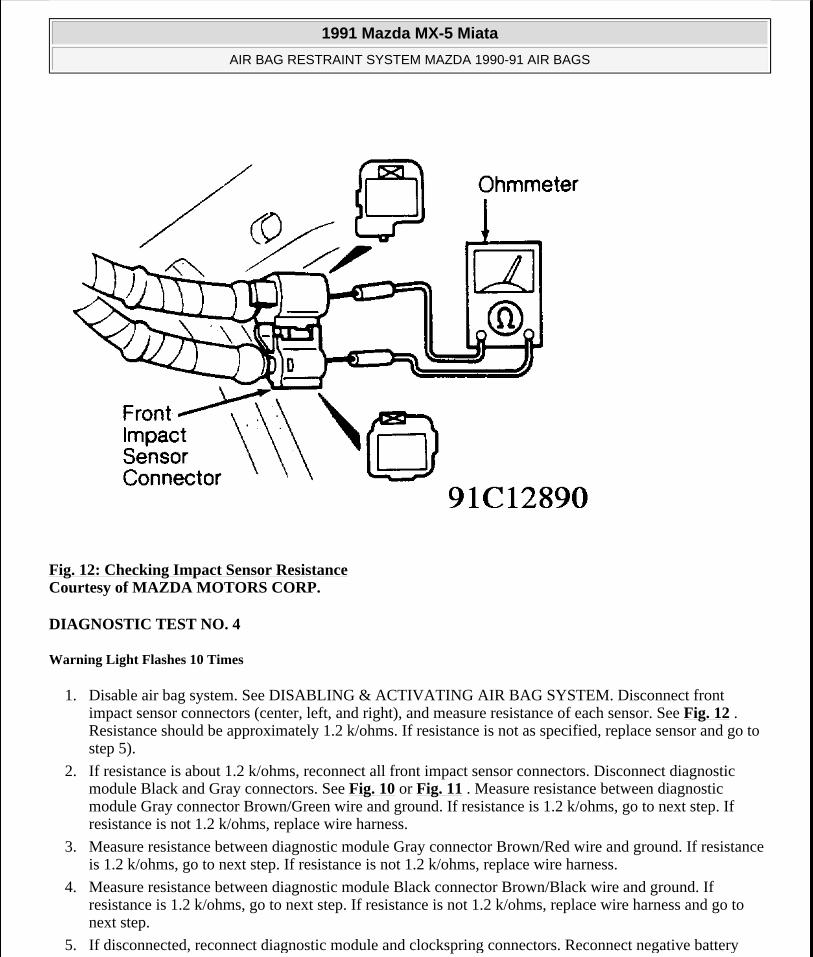
Fig. 12: Checking Impact Sensor Resistance Courtesy of MAZDA MOTORS CORP.
DIAGNOSTIC TEST NO. 4
Warning Light Flashes 10 Times
1. Disable air bag system. See DISABLING & ACTIVATING AIR BAG SYSTEM. Disconnect front impact sensor connectors (center, left, and right), and measure resistance of each sensor. See Fig. 12 . Resistance should be approximately 1.2 k/ohms. If resistance is not as specified, replace sensor and go to step 5).
2. If resistance is about 1.2 k/ohms, reconnect all front impact sensor connectors. Disconnect diagnostic module Black and Gray connectors. See Fig. 10 or Fig. 11 . Measure resistance between diagnostic module Gray connector Brown/Green wire and ground. If resistance is 1.2 k/ohms, go to next step. If resistance is not 1.2 k/ohms, replace wire harness.
3. Measure resistance between diagnostic module Gray connector Brown/Red wire and ground. If resistance is 1.2 k/ohms, go to next step. If resistance is not 1.2 k/ohms, replace wire harness.
4. Measure resistance between diagnostic module Black connector Brown/Black wire and ground. If resistance is 1.2 k/ohms, go to next step. If resistance is not 1.2 k/ohms, replace wire harness and go to next step.
5. If disconnected, reconnect diagnostic module and clockspring connectors. Reconnect negative battery
1991 Mazda MX-5 Miata
AIR BAG RESTRAINT SYSTEM MAZDA 1990-91 AIR BAGS
Microsoft
Sunday, July 05, 2009 2:11:16 PM Page 19 © 2005 Mitchell Repair Information Company, LLC.
cable. Turn ignition switch to ON position and check warning light operation. If warning light flashes 10 times, replace diagnostic module.
DIAGNOSTIC TEST NO. 5
Warning Light Flashes 4 Times
1. Disable air bag system. See DISABLING & ACTIVATING AIR BAG SYSTEM. Disconnect diagnostic module Black and Gray connectors. See Fig. 10 or Fig. 11 . Check continuity between Black connector Green/White wire terminals. If continuity is not present, replace wire harness.
2. If continuity is present, check continuity between Black connector Green wire and ground (1990 Miata), or between Gray connector Red/Black wire terminal and ground (all others). If continuity is not present, go to step 4). If continuity is present, check continuity between Black connector Green wire terminal and Gray connector Green/Black wire terminal. If continuity is present, go to step 4) (1990 Miata), or step 5) (all others).
3. If continuity is not present, disconnect rear safing sensor connectors. Check continuity between sensor terminals "B" and "E". See Fig. 13 . If continuity is present, replace wire harness. If continuity is not present, replace rear safing sensor.
4. Check rear safing sensor installation; repair as necessary. If installation is okay, disconnect rear safing sensor connectors. Check continuity between sensor terminal "A" and ground. If continuity is not present, replace rear safing sensor. If continuity is present, replace wire harness.
5. Disconnect diagnostic connector. Check continuity between Black connector Green/White wire and ground. If continuity is present, replace wire harness. If continuity is not present, repeat step 4).
1991 Mazda MX-5 Miata
AIR BAG RESTRAINT SYSTEM MAZDA 1990-91 AIR BAGS
Microsoft
Sunday, July 05, 2009 2:11:16 PM Page 20 © 2005 Mitchell Repair Information Company, LLC.
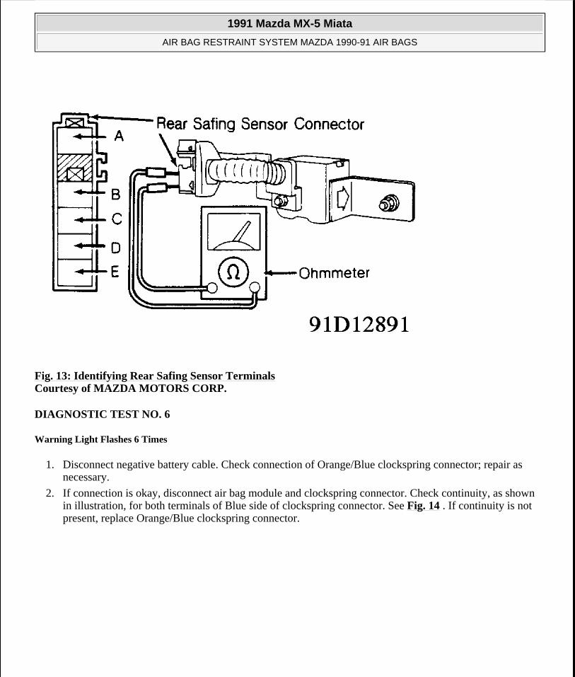
Fig. 13: Identifying Rear Safing Sensor Terminals Courtesy of MAZDA MOTORS CORP.
DIAGNOSTIC TEST NO. 6
Warning Light Flashes 6 Times
1. Disconnect negative battery cable. Check connection of Orange/Blue clockspring connector; repair as necessary.
2. If connection is okay, disconnect air bag module and clockspring connector. Check continuity, as shown in illustration, for both terminals of Blue side of clockspring connector. See Fig. 14 . If continuity is not present, replace Orange/Blue clockspring connector.
1991 Mazda MX-5 Miata
AIR BAG RESTRAINT SYSTEM MAZDA 1990-91 AIR BAGS
Microsoft
Sunday, July 05, 2009 2:11:16 PM Page 21 © 2005 Mitchell Repair Information Company, LLC.
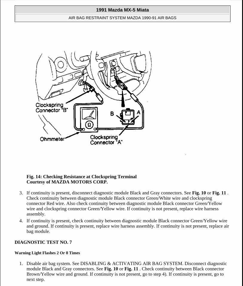
Fig. 14: Checking Resistance at Clockspring Terminal Courtesy of MAZDA MOTORS CORP.
3. If continuity is present, disconnect diagnostic module Black and Gray connectors. See Fig. 10 or Fig. 11 . Check continuity between diagnostic module Black connector Green/White wire and clockspring connector Red wire. Also check continuity between diagnostic module Black connector Green/Yellow wire and clockspring connector Green/Yellow wire. If continuity is not present, replace wire harness assembly.
4. If continuity is present, check continuity between diagnostic module Black connector Green/Yellow wire and ground. If continuity is present, replace wire harness assembly. If continuity is not present, replace air bag module.
DIAGNOSTIC TEST NO. 7
Warning Light Flashes 2 Or 8 Times
1. Disable air bag system. See DISABLING & ACTIVATING AIR BAG SYSTEM. Disconnect diagnostic module Black and Gray connectors. See Fig. 10 or Fig. 11 . Check continuity between Black connector Brown/Yellow wire and ground. If continuity is not present, go to step 4). If continuity is present, go to next step.
1991 Mazda MX-5 Miata
AIR BAG RESTRAINT SYSTEM MAZDA 1990-91 AIR BAGS
Microsoft
Sunday, July 05, 2009 2:11:16 PM Page 22 © 2005 Mitchell Repair Information Company, LLC.
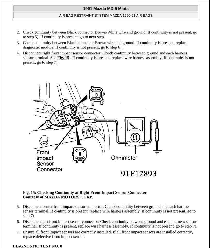
2. Check continuity between Black connector Brown/White wire and ground. If continuity is not present, go to step 5). If continuity is present, go to next step.
3. Check continuity between Black connector Brown wire and ground. If continuity is present, replace diagnostic module. If continuity is not present, go to step 6).
4. Disconnect right front impact sensor connector. Check continuity between ground and each harness sensor terminal. See Fig. 15 . If continuity is present, replace wire harness assembly. If continuity is not present, go to step 7).
Fig. 15: Checking Continuity at Right Front Impact Sensor Connector Courtesy of MAZDA MOTORS CORP.
5. Disconnect center front impact sensor connector. Check continuity between ground and each harness sensor terminal. If continuity is present, replace wire harness assembly. If continuity is not present, go to step 7).
6. Disconnect left front impact sensor connector. Check continuity between ground and each harness sensor terminal. If continuity is present, replace wire harness assembly. If continuity is not present, go to step 7).
7. Ensure all front impact sensors are correctly installed. If all front impact sensors are installed correctly, replace defective front impact sensor.
DIAGNOSTIC TEST NO. 8
1991 Mazda MX-5 Miata
AIR BAG RESTRAINT SYSTEM MAZDA 1990-91 AIR BAGS
Microsoft
Sunday, July 05, 2009 2:11:16 PM Page 23 © 2005 Mitchell Repair Information Company, LLC.
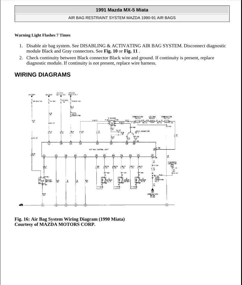
Warning Light Flashes 7 Times
1. Disable air bag system. See DISABLING & ACTIVATING AIR BAG SYSTEM. Disconnect diagnostic module Black and Gray connectors. See Fig. 10 or Fig. 11 .
2. Check continuity between Black connector Black wire and ground. If continuity is present, replace diagnostic module. If continuity is not present, replace wire harness.
WIRING DIAGRAMS
Fig. 16: Air Bag System Wiring Diagram (1990 Miata) Courtesy of MAZDA MOTORS CORP.
1991 Mazda MX-5 Miata
AIR BAG RESTRAINT SYSTEM MAZDA 1990-91 AIR BAGS
Microsoft
Sunday, July 05, 2009 2:11:16 PM Page 24 © 2005 Mitchell Repair Information Company, LLC.
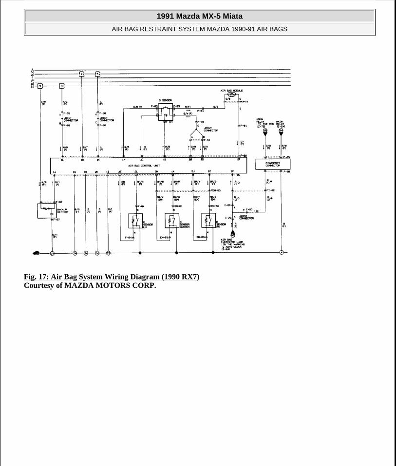
Fig. 17: Air Bag System Wiring Diagram (1990 RX7) Courtesy of MAZDA MOTORS CORP.
1991 Mazda MX-5 Miata
AIR BAG RESTRAINT SYSTEM MAZDA 1990-91 AIR BAGS
Microsoft
Sunday, July 05, 2009 2:11:16 PM Page 25 © 2005 Mitchell Repair Information Company, LLC.
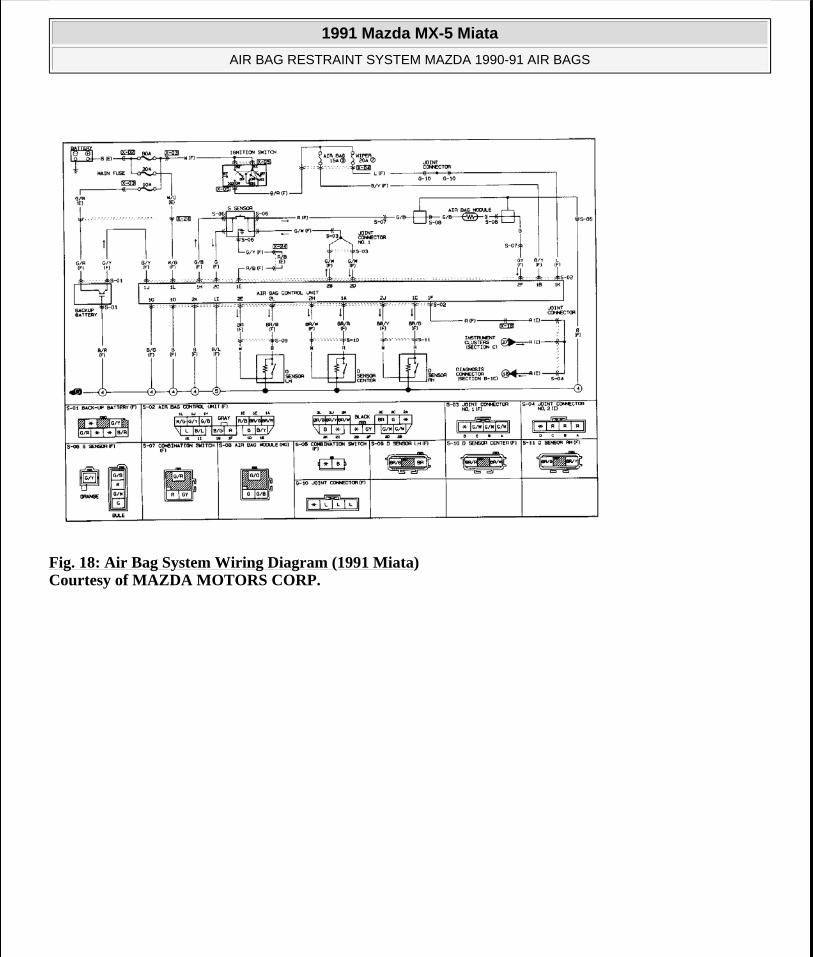
Fig. 18: Air Bag System Wiring Diagram (1991 Miata) Courtesy of MAZDA MOTORS CORP.
1991 Mazda MX-5 Miata
AIR BAG RESTRAINT SYSTEM MAZDA 1990-91 AIR BAGS
Microsoft
Sunday, July 05, 2009 2:11:16 PM Page 26 © 2005 Mitchell Repair Information Company, LLC.
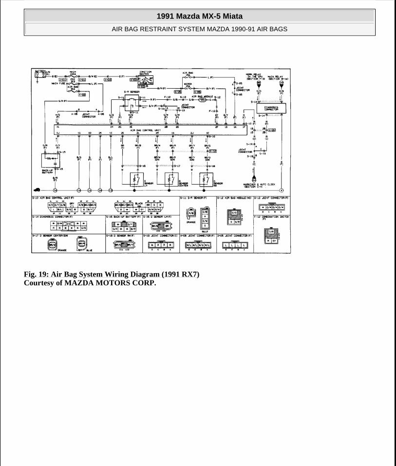
Fig. 19: Air Bag System Wiring Diagram (1991 RX7) Courtesy of MAZDA MOTORS CORP.
1991 Mazda MX-5 Miata
AIR BAG RESTRAINT SYSTEM MAZDA 1990-91 AIR BAGS
Microsoft
Sunday, July 05, 2009 2:11:16 PM Page 27 © 2005 Mitchell Repair Information Company, LLC.