describing nonstandard gears an alternativeto the … alternativeto the rack '5hlft-coefficient...
TRANSCRIPT
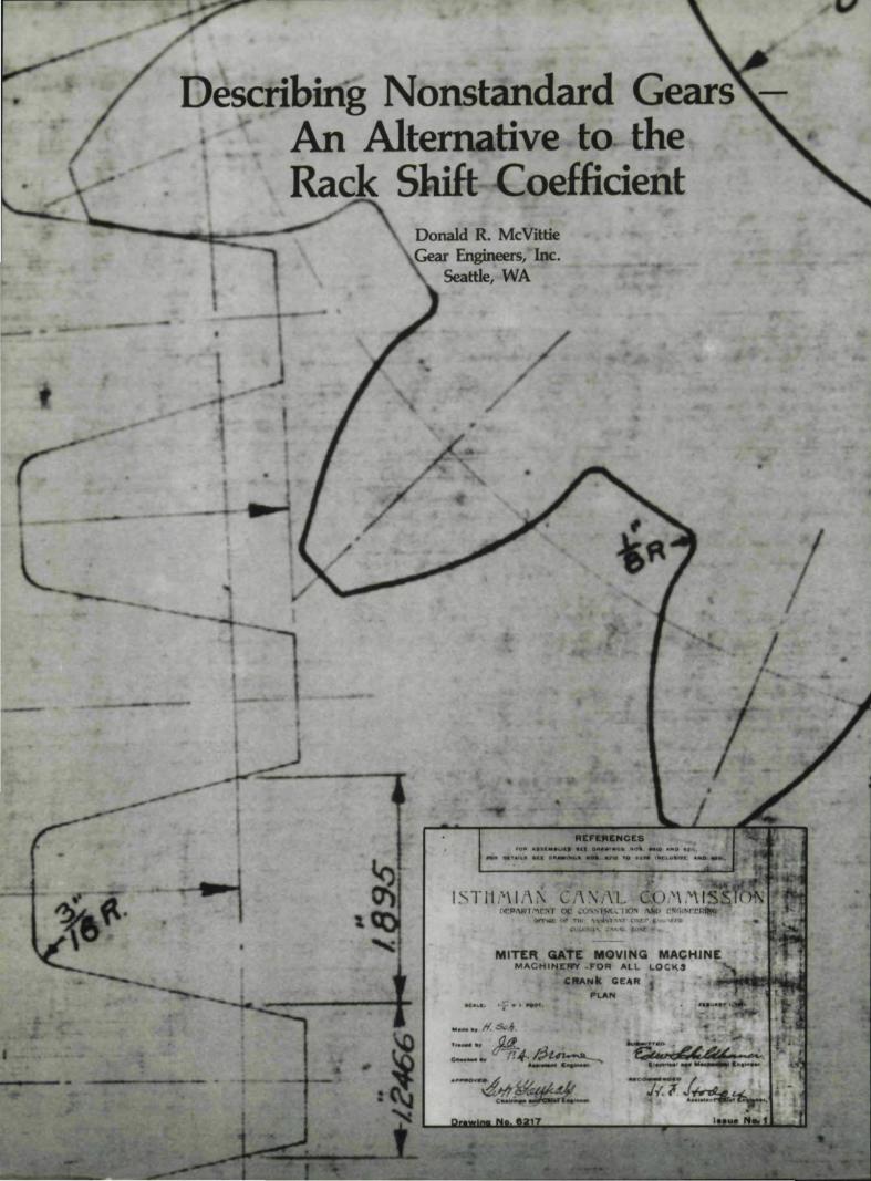
Describing Nonstandard GearsAn Alternative to theRack '5hlft -Coefficient
Donald R. McVittieGear Engineers, Inc.
Seattle, WA
/
•
PLAN
MACHIN£WY .FOR "'1..1. L.OCK'
ellANIt !;ElIIR
r-'1141_1.1:. • ,._ • i NlJI.

AbstractThe racks:hift method of describing gears mad with nonstan-
dard addendum diameters (tip diameters or nonstandard tooththickness) has serious lLmilations, since the nominal pit.ch of the cut-ting tool, which is required for the calculation of rack shift coeffi-cient, may not be available to the designer, may vary as the toolis sharpened or may be cliffefen.! for the gear and tits mate.
The details of the calculation of rack shift coefficient are not stan-dartiized, so ~ere is little agreemem between analysts aboll~the valueof "x" for a given nonstandard gear or g ar pair. Two commonmethods to calculate rack shift coefficient are described in this article.
This article proposes a different nomenclature for nonstandardgears. using the involute function of th transverse pressure angleat 'Ille d:iameter where 'the space width is equal to the cireular tooththickness. This is calculated from the funcbrnenlal relationships be-tween number of teeth, normal base pitch, axial pitch and normalbase tooth thickness, -
This dimensionless value, calledT", is used with th.e add srtdumdiameter and fa.ce width to describe a single gear, A pair ,of gearsis described by the same system, by adding center distance andbacklash to 'the parameters.
In'lrodudionThe use of dimensionless factors to describe gear tooth
geometry seems to' have a strong appeal. to gear engineers.The stress factors I and J, for instanc~,are well establishedin AGMA literature, The use of the rack shift coefficient "x"to describe nonstandard gear proportions is common inEurope, but is not as commonly used in the United States.When it is encountered in the European literature or in theoperating manuals for Lmported machine tools, it. can be asource of confusion to the Americaa engineer.
Even those who use the rack shilt method do not agreeon how to evaluate the rack shift coefficient of a specific gearset. As a test, the author sent a set of data fora simple spurgear set. to seven gear engineers in the U.S. and Europe withthe request ,that they evaluate the "x" factor. Of the six replies,no two results were the samel The value of the rack shift coef-ficient "x" varied by more than .20%. The gear data and theresults are tabulated in Appendix C.
This article proposes that these nonstandard gears bedescribed by a different parameter, the involute function of
AUTHOR:
DONALD R. McVITTlE is president of Gear Engineers, Inc" Seat-tie, WA, a professional engineen'ng company specializing in geardesign. analysistmd gear capacity studies. He is also diredor andmember of the underwriting and claims committee for GMJ~ Ltd"a product liability insr.mmce company owned by a group of gearmanufacturers, He was Executive Vice President of The Gear Wor/c:s..Seattle, Inc. W1til his reti~em~t in 1986.
A graduate of University of Michigan with a degree in mechanicalengineering, Mr; McVittie is an active member of AGMA, where heis Vice President of the Technical Division. He was AG/vlA presi-dent in 1984/85. He is .a licensed professional engineer in the Stateof Washington, and member of ASME, SNAME and SAE and theauthor of several technical papers.
January IFebruary 1988 l' 11

the transverse pressure angle where the tooth thickness equalsthe space width.
Before describing the proposal, the rack shift method ofdescribing nonstandard involute gears and some of its limita-tions are discussed.
Rack Shift Coefficient - Two DefinitionsOutside Diameter Method. One definition of rack shift
coefficient is given by Maag:(l)'The amount of the radial displacement of the datum line
from the position touching the reference circle is termed ad-dendum' moddicazion, This amount is given a positive signin the calculations when the displacement is away from thecenter of the gear, anda negadve sign when towards the'center of the gear .. , .The addendum modification coefficient~ is the amount of addendum modification measured in termsof the diemetral pitch or module,
Addendum Modification = x (or x.m) (1)p
The dimensions of the gears can be determinedas the so-calledzero backlash gearing by means of a system of equations.(In practice the backlash is obtained by the tolerances on thetheoretical, nominal dimension.)"
This definition, which will be called the outside diameter(OO) method, is useful because, if root clearances are keptstandard, the center distance can easily be calculated withoutconfusing the calculation with considerations of operatingbacklash. (See Figs. 1 & 2.) It is dear that, even without usinga dimensionless coefficient .
C = 001 + Dr2 + c (2)2
whereDol = Outside diameter of pinionDr2 = Root diameter of gearC = Center distancee =, Root clearance.
The geometry is calculated as Hthe gear were cut by feedingill hob in from the outside diameter to standard depth, thenside cutting to achieve the desired backlash.
The' gear data block includes "backlashaUowancein thisgear", which specifies thearnount of this side cutting . Forgears which are to run on widely spread centers, this backlash
Fig. ~- The outside diameter method.
12 Sear Techno'iogy
'----- C --..-.I
Fig. 2 - Center distance using constant radial clearance.
allowance must be negative to provide reasonable operatingbacklash. Negative backlash allowance is a difficult conceptwhich can lead to false expectations of root clearance, -
This is a simple mathematical convention, but it is not theway gearsare made. In real life, the cutter is fed in until thedesired tooth thickness isa.chieved. The resulting rootdiameters are not the same as those assumed in the originalconvention, so the root clearances on which the conventionis based are not standard.
Nonstandard root clearances are not much ofa problemif they are greater than expected, but they can lead to inter-terence problems in those gears which have negative "backlashallowance" in order to operate properly on spread centers ...(See fig. 3.)
The interference can be alleviated by reducing the outsidediameter to restore the standard clearance, but this throwsthe engineer into ill loop, since the x factor is based on the00. Lorenz(2.)introduces a K factor (tip modification factor)to dean this up without recalculating the x factor.
This definition has a more subtle problem, since helicalgears and spur gears with the same normal generating tooththicknesses do not have the same x factor, even though itseems they should. This question will be covered later in thisarticle.
Tooth Thlcknes« Method. Another definition of rack shiftis related to Ute actual position of the cutting tool when cut-ting the thickest allowable teeth for the design underconsideration ..
Wndtsn - '1'12)x = (3"where
tsn = Tooth thickness at standard (generating) pitchdiameter.
Pnd = Normal diametral pitch;:Pc = Cutter profile angleThis is dimensionless, since the tooth thickness is multiplied
by the diametral pitch or divided by the module. We shall

call this the tooth thickness ('IT) method. (See Fig. 4)The IT method eliminates the problems with negative
backlash allowanceand misleading root clearanee assump-tions inherent in the OD method. It ofl,ers little help incalculating center distance if tooth thicknesses are known,or in calculating tooth thicknesses to operate at a specifiedcenter distance. In this method, the outside diameters of thegears are calculated from the center distance, the rootdiameters and the required root clearances.
DOl =2{C-c) - Dr2: (4)If two gears are operated on acenter distance equal to the
sum of their standard pitch radii plus the sum of their rackshifts calculated by 'the IT method, the operating backlashwill vary in a complex manner with the sum of the rack shifts.Backlash is zero when the sum or rack shifts is zero, but itmust be calculated from operating pitch diameters andoperating tooth thicknesses when the sum of rack shifts isnot zero. The time required to perform this lengthy iterativeprocess usually precludes 'the development of an optimumdesign. -
Most of those who responded 'to the sample problemassumed a "backlash allowance" and adjusted the tooththicknesses ,arbitrarily to define a hypothetical "zero backlashset" .•The' differences :in their assumptions account for someof the differences in their calculated "x" factors.
Cutter Standards arid Stl:mdard Racks. In order to makeany of the definitions of rack shift dimensionless, the designermust assume a cutter diametral pitch or module. This isusually done in terms ofa hypothettcal standard rack byassuming that the rack geometry is "standard" where the tooththicknessand the spac-e width of the rack are equal toonehalf of the rack's circular pitch.
This is ground. "tool designers and gearmachines operate with base pitch,
regardless of what is marked on theof the toot Short pitch hobs,
single tooth rack shaper cutters, singletooth grinders and two wheel grinders ar
Fig. 3 - An exampleof geMS interferingin the root withbacklash. The hobwas ~ in to stan-dard depth.
GENERATING DIAMETER(PREUUIII ANGLI lQUALI .c)
Fig. 4-Addend-urn modification factor by the looth thickness method.
beyond standardization by the "half circular pitch" method.What is the designer to do,? Usually an assumption is made
by the designer and ignored by the manufacturing depart-ment. The result can. be a.surprise, usuaUy discovered. on theassembly floor.
Earlier PublicationsFinding an easy way to calculate the dimensions of
nonstandard gears has been the 5ubjectof countless paper-sand articles. As early as 1911, the Isthmian (P'anama) CanalCommission(J) used 1 DP' oversize spur pinionsin the gatemechanisms for the Gatun and Miraflores locks. These gearswere made on special Gleason gear planers from a layout,another method which is hard to describe in terms of a stand-ard rack fonn ..
As the advantages of nonstandard gears became betterrecognized, many authors tried to develop systems for "stan-dardlzed" nonstandard systems ..Maag: offers pages of charts,nomographs and advice on this subject. An interesting paper. (4).. .. 1;'"-
by Grosser provides eight pages of charts to help withthese calculations. Farrel(S) also provides guidance in select-ing the proportions of gears intended to operate on spreadcenters. Most of this work dates from the days oJ mechanicalcalculators and 'tables of logarithms, when the difficulty offinding the value of an angl Irom its involute function wasavoided whenever possible to save calculation time,
Compu.ters and dle Inverse InvoluteToday we can find the arc involute as easily as we find
the arc eosine, Even pocket calculators are easily programmedto givean accurate result. There are many algorithms.Cooper(6),. Errichello(lI and Laskin(8) all work and are read-ily available. Easy access to the arc involute frees us up tooptimize nonstandard gears if we can ri.nd a more direct ~ayto calculate center distance, backlash and limit diameters fr-omtooth thicknesses, or vice versa.
Summary of This ArticleThis article will demonstrate thalt the involute function o.f
'the transverse pressure angle, where the tooth thickness isequal to thespace width, called the 'T' factor, is a useful way
January/February 19,88 '13

to describe nonstandard gears. With this parameter, a seriesof simple equations can be developed, which s.implifynonstandard gear geometry calculations and reduce iteration.The"]" factor is
• Dimensionless• Easily calculated• Independent of helix angle• Independent of the cutter geometry• Independent of the mating gear• Unique for the geometry of the gear described.
Nomenclature and DefinitionsDefil1itiotl$. Symbols are defined where they are first used
in this article. For convenience, a list of symbols is providedin Table L
The subscript ''1'' refers to the pinion, and the subscript"2" refers to the gear.
Fundamental! PilIamet·ers of the Involute Tooth FormThe involute portions of a.meshing gear pair can be Com-
pletely described in terms of a short list of fundamentalparameters.
Numbers of Teeth. The number of teeth on each gear must
Table 1 - Nomenclature
WhereFirst
Symbol Description UsedB Backlash in the plane of rotation Eq. 5~ Backlash normal to involute profile Eq.7C Center distance Eq.2c Root clearance Eq. 2o, Base circle diameter Eq. 5Dol Outside diameter of pinion Eq. 2Dr2 Root diameter of gear Eq.2m Metric module Eq.lN1 Number of teeth in pinion Eq.6Nz Number of teeth in gear Eq.6P Diametral pitch Eq.1Pnd Normal diametral pitch Eq.3p Transverse circular pitch Eq. 14Ph Transverse base pitch Eq.5PN Normal base pitch Eq.7
p" Axial pitch Eq. 9I
T Tooth thickness Factor (inv 91) Eq. IS'II t Transverse tooth thickness Eq. 14I tb Transverse base tooth thickness Eq. 5i tbn Normal base tooth thickness Eq.7tsn Tooth thickness at standard
(generating) pitch diameter Eq .. 3x Rack shift coefficient Eq.1,p Transverse pressure angle Eq. 14,p' Transverse operating pressure angle Eq.5¢I Transverse pressure angle where space
width equals tooth thickness Eq.13,pc Cutter profile angle Eq.3th Base helix angle Eq.7
14 Geor Technology
be known before the geometry can be defined.Base Pitch. The base pitch must be determined from the
cutting tool. or arbitrarily if the gear is to be made on amachine where base pitch is adjustable .. Base pitch can bemeasured in the normal plane or the plane of rotation.
A;dal Pitch. Axial. pitch, which determines the helix anglesof the gear set, is required to define the geometry.
Base Tooth Thickness. Base tooth thickness, which deter-mines all of the tooth thicknesses of a gear, must be estab-lished for each gear. Base tooth thicknesses can be measuredin the normal or transverse' plane.
Center Distance and Backlash.. If both base tooththicknesses of a gear pair are known, either center distanceor backlash is required. The other can be calculated ..[f threeof the four; tbI, tb2, C and B, are known, the fourth can becalculated.
Blank Dimensions. The outside diameters of the gearblanks are usually determined by the involute geometrychosen, thecutter addendum and the root clearances desired.They are required, along with the face widths, to completelydefine the gear geometry.
Root Fillet Geometry. The root trochoidal form is deter-mined by the cutting conditions. It is beyond the scope ofthis article, since it does not affect the involute portion ofthe teeth, but it isfundamental to the strength ·of the teeth,For good control. the root fillet coordinates or the cuttingmethod and cutter fonn must be specified.
A Pair of GearsGear designers are usually intersested in a pair of gears in
mesh, since, like Adam without Eve, one gear is more or-namental than usefuL It can be demonstrated that for twogears in mesh:
iov ,p' _ tbl + tb2 +B - Pb
Dt.l + Dt.2(5)
where1jJ'fbI
thZ
PhB
- Transverse operating pressure angle- Transverse base tooth thickness of pinion- Transverse base tooth thickness of gear- Transverse base pitch - :1I'Db/N- Backlash measured in the transverse plane and
in the plane of action- Base circle diameter of pinion- Base circle diameter of gear
DbI
Db2
(Derivations for Equations 5, 12, 13, 14 and 21 are includedin Appendix A.)
For either gear or pinion:
(6)
where
N - Number of teeth
If Equation 6 is combined with Equation 5 and the resultis multiplied by cos %/cos %, we have the surprising result:

where'Ph - Base helix angletbn - Normal base tooth thickness 'of pinion or gearPN - Normal base pitch~ - Normal backlash measured normalta involute pro-
file. This is the backlash wh:ich would be measuredby a feeler gauge inserted between the teeth.
Equation 7 demonstrates that til is independent of ifib. Thisimplies that as a. pair of spur gears are made "more helical"by increasing the helix angle, holding the normal base tooththickness constant and holding the axes paralleljhe centerdistance increases in inverse proportion to the cosine of thebase helix. angle and the operating transverse pressure angleremains constant. A similar equation appears in. Section 1.35of Maag for checking the calculation of base tangent length.
The tight mesh condition, as with a rutting too] or a mastergear, is a special case where the backlash is zero.
U the center distance is known:
, Dbl + ~l PN(N1 + N2),cost/> - , , - ::....:..:..---"----'''-2C 211' C cos I/t'o
I/t'o - sin-1 (PN)PK
(8)
(9)
wherepx - axial pitch.
Note: For spur gears, the base helix angle is zero. The valueof cos I/t'o is 1.0. Most computers will accept a very largevalue of PXI such as l.OE+9, without significant error, andeliminate the need fora separate routine for spur gears.
If EqUation 7 and Equation 8 are solved for t/>' and equated:
A.' -1 (PN(N, 1+Na) )'I' - cos ! ---=----='-
2'11'" Ccos 1/1,
_ inv-1 ('II'"(tbn1+~~+BN-E-J)PN(N1+Nz)
(10)
If the cutter and numbers 'of teeth are fixed, this simplifiesto:
(11)
where
. - (N +N)K} - a constant, PN 1 2
:11'
K2. - a constant, BN-.PN
This equation is partieularly helpful when a gear set mustbe designed to fm a given center distance, since the combined,effects of increasing tooth thickness and increasing base helixangle {or decreasing axial pitch} are shown in one equation.
Once the sum of the base tooth 'thicknesses is known, itmust be divided between the gearand pinion in accordancewith the designer's priorities for balanced strength, sliding
velocities and whole depth.Gear Pairs With NOP1~.Pa.r;allelAxes. Equation 7 is derived
from the assumption that the axes of rotation of the matinggears are parallel, (The base helix angles are equal.l H thisis not the case, as in hobbing, shaving and in spiral gears,a more general relationsrup must be sought, in which the nor-mal operating circular pitches of the mating parts are equalat the operating pitch diameters, and the Sum of the norma]operating tooth 'thicknesses plus the normal! backlash is equalto the operating; normal circular pitch. This leads to Equa-tion 12, which must be solved by iteration.
N'- , N--'.' N (tbl) N (tb2) , (BN) (-)IlnVt/>l+ Zlnvt/>2,-l ,- + 1 - + 'II'" - -'11'"12ObI Db2 PN
It can be seen that if the axes of 'the gears are parallel, so'that the transverse operating pressure angles, (t/>\ - q,'2 -t/>/), and the base helix angles are equal, Equation U reducesto Equation 7.
One Gear. It has been shown by Grosser that the pressureangle where the tooth thickness is equal to the space widthcan. be found by
(U)
pressure angle where space width equals tooththickness.
'6th .ANNUAL AGMAGEAR MANUFACTURINGI
S,YMPOSIUMAPRIL 10-12, 1988
AJ"e you 'economically making ge.ars to 'specifications? I
Can you ma1lntal_1'I quality while, Impr,ov,lng 1PrOdUCtlVltY?'1
AGMA's Gear Manufacturlngl Symposium Is an Intenseprogram that provides ,obJective ,answers. Offered bythe' Industry's association, with pr,esentatlons by Industryexperts. You''IIlearn how to pr.event gear manuf.acturlngpr.oblems,as wen as Improve quaJlty and productivity.
TOpiCS will Include:• Gear Cutting • G.ear Finishing
'. Inspection and Quality Control• Designing for Manufacturing' lEase
A tour of Harley-Davidson's manufacturing:facility will be inoluded in the' program.
REGISTRATION before February28, $375.001. - after March 1. 1988 $450.001
($11)0' dls:Qounl available for AOMA members)
To register or receive information,. contact:American 'Ges'r Manufacturers Assoclatlonl
1500 King: Street, Suite 2011, Alexandria, VA 223,14or call (703,) 684-0211
CIRCLE A.-3 ONI REAO.ER REPLY CARD
January/F,ebruary 1988 15,

In Grosser's genera] case:
(14)
where
t - tooth thickness at the diameter where cp is measuredp ~ circular pitch at the same diameter.
The similarity between Equations Sand 13 has led to. asearch fer a way to express the fundamental proportions ofa gear pair in the same terms, as dimensionless ratios of to,Ph and N, independent of the cutter geometry or the unitsof measurement,
"T"FactorDefinition. The author proposes that the involute of the
pressure angle in the transverse plane at the diameter wherethe tooth space is equal to the tooth thickness, be used asthe dimensionless comparison factor. This factor, called T,for transverse tooth thickness factor, is dimensionless, easilycalculated and extremely useful. It would also be possible to.use the pressure angle at this diameter, which is in morefamiliar units, at the expense of an additional mathematicalconversion. This angle will be shown for easy reference inparentheses as (cf>T) wherever numerical values for T aileshown, for easy reference ..
Ca.lculan:on of T. Equation 13 can be restated by multiply~ing it by cosVtb/cosVtb, in terms of normal tooth thicknesses
IJ J'J J-J .E.~\H DO;:: . Possibly,
you hue· never heard 01 f[w7. IBul, thousands 01 our variety 01gear prOducing machines have Ibeen manufactured lor 40 years.
GEAR SHA PERSMOOel.'GS8·2 {S-Ca • 2- face)Model o\'GS20·5 {20- cia • 5' facel
(ILLUSTRAi TED AT f..EPTJ
OTHER MACHINESBevel gear' ge'i"Ierstor9 ,spiral & SHilghlcuner Q'It\de(s. shaping. shaVing , hObCyeiclid gear m~lrersGear gnoder:s. 51HIIght conical, IrHsrnal
eyclold al 5. ~worm" wheelGear hobbers '. Inch to !!IO foot dlamel'erGeaf hon,ng macrsnesGear noise lestlflg macmnesGear shaversHYPOjd generalors. lappers & testersRack shapersSpline shaH milling macttmesrccm chamfenng machln.esWorm wheel hObbers(USER REFERENCES AVAU8I£)
INTBQPUCTORY pRICEModel ·'0$B·2 $27.750 r.doe.dlo $19.450Model IGS20·5 $79.995 led"ce<l to $55,950
SPECIFICATIONSMal(~mum gear diameter 20~M,axtmum race Yftdth '5-Mailimum pucn ,4DP fUlltTE'D OFFER)
Ineludes: (50) change gears Visit our Oelroll "DEMO·CENTEfl" 10 see),Iagnet'c ch,p conveyor to, your,.If: {313) ·651·1200 [.D!ck Flke)
U]\n-J1:Af10> OF .In.:,,, as 0<1 profits I
TERCO'NTINENTAI.'OUSTRIESORPO'llATED LOS
P. O. BOX 36754ANGELeS. CA 90036
(213) 933·0311
CIRCLE A·9 ON READER REP,LVCARD
and normal base pitch, as:
(15)
This is the most convenient general form, since it is validfor both spur and helical gears ..
Whe.n two gears are considered, T can be substituted intoEquation 7 giving:
. ,TIN1+T2N2+1F(BNIPN) '(16)mvtJ! - ... _N} + N2
The term "BNIPN" is identical to "B/pb'" so that backlashcan be taken in either sense, as long as the value at base pitchis consistent.
Some examples will illustrate the uses of this concept.Fixed Center Distance Gears. Engineers are often asked to
specify a gear set with a specific ratio to nlesh at a given centerdistance and a specified backlash, Usually, the ratio will notHt thecenter distance with spur gears made to standard pro-portions and with standard (or available) tooling. The choice,then, is to use oversize spur gears, helical gears or oversizehelical gears. The possibilities are endless, and thecalcula-honsare repetitive, so the tendency is to use the firstreasonable resolution without really considering thealternatives.
A simple calculation procedure using the Tractor wiH beiillustrated by a numerical example. ]n these examples, calcula-tions will be made for theoretical gears, representing thetightestcenter distance expected and the maximum materialcondition of the gears ..
Consider a 35/23 ratio (1.52174/1) and a 6.S00M centerdistance. Assume that 5 DP 20" (PN - .5904) tooling isavailable, and the desired normal backlash is .010·.
The author has found that 25° is a reasonable upper limitfor the transverse operating pressure angle .of sets like this,so calculations will begin there. From EquationS Vtb -22.311" and from Equation 9 px - 1.5552'.
Rearranging Equation 16, we get: B
TIN1+T2N2-inv¢'(N1+N2)-T (~) (17)PN
With the value of T1Nl + TaN2 known, the distributionof base thickness between the two gears is completely up tothe designer's judgment. Some of the options are:
Balanced Sliding. If a balance between approach andrecess action is desired, T1 should be approximately equalto T2, and
invcp'(N1+N2) -1F(BN/pN)
N]+N2
., 1rBN- mv¢ - --~-
PN(N1+N2)
Substituting and solving for T:
T- .02905791,(¢T - 24.7555°)
T
(18)
Rearranging Equation 15:
TN PNtbn ~ + .SPN
1r(I9)

For over 7S years Barber-Colman, Maag andLorenz have established mdepsndent reputationsfor e,xce'llenoe in specia'ity tools forcutting tooth forms and similar preci-sion profiles. Now tne combined cut-ting tooll product line of these threelegends is avallable trom a sling/e'source ... Pfauter-Maag Cutting Tools.
If your application requires hobs, shaper cut-ters, milling cutters or speciall form toots. you now
have a world of choices by calling onenumber ... (815) 877-8900.
Pfauter- Maag Cutting Tools,1351 Windsor Rd.,Loves Park,lL 61132.

Substituting, Ibn = ...4208' tor the 23 tooth gear and .4863·for the 35 tooth gear.
The tooth thickness values are converted to the transverseplane, and the tooth thicknesses at the generating diametersare calculated, For standard tooling and standard rootclearances, the gear ~O's will be 5.558" and 8.247", and thetip lands will be .141' and .145", respectively.
For the pinion, the arc of recess action is 20.50, and the
arc of approach is 20 ..2°. The sliding velocity at the gear tipis 90 inches per second at 1200 pinion rpm, and at the piniontip it is 87 inches per second. The complete geometry of thisgear set is shown as Example 1 in Appendix B.
Balanced St~ength. H balanced strength is the first con-sideration, a solution must be found by iteration.
For external gears with moderate ratios, the iteration canbe shortened by setting the T values in inverse proportionto the numbers of teeth, so that the product T x N is a con-stant. This is equivalent to setting the base tooth thicknessesequal to each other. (See Equation 15.)
From Equation 17, values for T are .036638 (q,y -26.6303°) for 23 teeth and .024077 (¢T - 23.3217°) for 35teeth.
Substituting these values into Equation 19, the base tooththicknesses are .45356·.
The outside diameters are 5.654.· and 8.151". The tip landsare .1225" and .1574".
The resulting J factors for bending strength are .511 and.458. The complete geometry of this gear set is shown as Ex-ample 2 in Appendix B..
This is only one of an infinite number of possible solutionsto the problem. Although it provides a reasonable balance,since the J factors are within 6% of the mean, better balancebetween the bending strengths can be obtained by increas-ing one base tooth thickness slightly at the expense of theother. The sum of the base tooth thicknesses must be heldconstant to maintain the operating backlash.
For moderate gear ratios, base tooth thickness is nearlyproportional to root tooth thickness, and bending strengthis proportional to the cube of root tooth thickness, In ourexample, a. 2% change (.009') in base tooth thickness willmake the difference, since (1.02)3 - 1.06. The resulting Jfactor is .48 for pinion and gear. The designer must judgeif such a small change is really significant to the performanceof the finished parts. The complete geometry of this gear setis shown as Example 2A in Appendix B.
A higher strength rating might be obtained by increasingthe operating pressure angle at the risk of higher noise anda smaller contact ratio. The T factor system allows thesepossiblines to be explored with a minimum of repetition, anda clear idea of the effects of each change.
Tight Mesh Center Distance. Once the geometry of thework gear is established, the engineer next usually needs theinspection data. If the work gear is to be inspected by themaster gear-test radius method, the operating center distancewith the master gear will be required. In this example a mastergear with a standard tooth thickness - the space width equalto the tooth thickness at the generating pressure angle-willbe used.
T for the master gear is then equal to the involute of the
18, Gear Technology
transverse generating pressure angle.
'. . _ sin¢cT - inv (sin 1(__ ))cosrh,
T == .019203, (<frr = 21.6969'°)
T for the 35 tooth work gear is .024077, from Example 2.Substituting the appropriate values in Equation 16, inv ¢'
= .022302 and ¢' = .3972 radians. From Equation 8., thetight mesh center distance is 6.0583". The complete geometryof this gear set is shown as Example 3 in Appendix B.
Sh.aper Cutting Conditions. H the gear is to be cut witha pinion shaped cutter, the calculation is done as in theprevious example, except that allowance must be made forthe sharpening condition of the cutter ..The operating centerdistance with the cutter is necessary for the calculation of in-terference and form diameters with the shaper cutter. It isusually calculated for two conditions, new cutter and thin-nest usable worn cutter,
The base tooth thickness of the cutter can be taken fromthe cutter drawing or from span measurement of the actualcutter. The second alternative is usually best if a.worn cutteris to be used to cut the part.
For example, consider a 71 tooth internal spur gear to becut with a. 20 tooth 3 Pndcutter, to a base tooth. thicknessof .1460". For the geat, T = .015559, th = 20.2787°. T, aninvolute function, must be positive, so the absolute value ofN must be used. In the rest of the calculation, the numbersof internal teeth and internal diameters ,31'e considered
{20J
negative.The results are shown in Table 2.
Table 2
Cutter Data New Cutter Worn Cutter
too .6120" .5247'T factor .019156 .005220¢T 21.6798° 14.21600
¢' 19.668° 21.844rC 8.482" 8.605"Example No. 4 5
Mesh With A Rask, The T factor system can be used toanalyze rack and pinion meshes by assuming that the rackis a gear with a very large number of teeth, such as 9999.This eliminates the computational. problems caused by infinitevalues fortb' Cand Nz. The T factor for the rack is equalto its transverse pressure angle. As an example, we will ex-aminea 33 tooth spur pinion, cut with a 5 Pnd 141.5° hobto a base tooth thickness of .4131", in mesh with a specialrack. The pinion was designed fora. special job requiring lownoise and high beam strength, The rack pressure angle of 80
was chosen to minimize separating forces and provide a.max-imum contact ratio for quiet operation.
The rack circular pitch required to match the pinion basepitch is .6143". T is then the involute function of 8\ or,0009141.
This unusual gear set was built for a linear motion de-vice, similar to a planer. (See Figs. 5~7.) It illustrates theability of the T factor to describe the gear geometry and to

facilitate the necessary mesh calculations, even if the two partsare made with widely diHerentcutting tools, as is the casehere. The complete geometry of this gear set is shown asExample 6 in Appendix B.
Mesh With A Hob. The T factor as derived is valid formeshes where the axes of rotation of the two members areparallel, but not valid in hobbing or shaping with a rackshaped cutter set in. the normal plane. In these cases, it issimple to convert the tool. geometry to its equivalent rackin the transverse plane by calculating its transverse pressureangle using Equation 17,. For example, the 35 tooth helicalgear of Example 2 might be cut with a standard hob witha 20Q norma] profile angle. The transverse pressure angle ofthe hob, ¢T = 21.69710 and T = .019204. Example 7 inAppendix B shows the complete geometry of this gear set,
Establishing Root and Outside D.iameters..The examplesgiven here establish the foot diameters of the gear and pin-ion from the cuttirlg conditions, using the generating diameterand tooth thickness to establish the cutting position of thecutter, and calculating the tip position of the cutter from theactual. cutter geometry. This allows the use of different toolsfor the gear and pinion if desired. The shaper cuHer and hobexamples show how this works. The outside diameters arechosen to give standard root clearances from the rootdiameters of the mating parts, except in the cutting tool ex-amples, where the root clearance with the cutter is zero.
The resulting whole depths vary from standard in orderto maintain the designed clearances. This system is not re-quired, but it has the advantage of automatical.ly maintain-ing equal cutting depths for gear and pinion.
Limit Diameter for Minimum Tip Land. Pinions designedto operateon widely spread centers run the risk of havingtip lands which are too small for good operation or for proper
Fig. 5 - Pinion inmeshwithspecial rack.
F.ig.. 6-SpecialBD generated .r.1ck.
heat treatment. An .adaptation of the T ta.etor allows a quickapproximation of the maximum usable diameter limited byminimum tip land. This approximation is based on thepremise that a minimum value for tip land should be.300"/Pnd•
From Equation 14 the involute function at .any diameterwhere the ratio of tooth thickness to circular pitch is known.can be cal.culaled. If we assume ,that the pressure angle atthe limiting outside diameter will be appro.xima'lely 40°, 'theratio of base pitch to cwcular pitch at the outside diameterwill be .776,theoosineof 400
• These assumptions let lIS derivethe following:
.!'(tbn - ·08PN)mvtbJDmal< - --'-..:::::.:...-....:..:.:;..NPN
Equation 21 is a good guide to maximum diameter ferpreliminary design of pinions, but the actual tip land shouldbe calculated beIor1! the design is finalized ..
This approximation is not IlRfuli for gears with largenumbers of teeth, since the 40" approximation is unrealistic
for gears with more than. 40 teeth. This limitation isnota serious one, since the problem is encountered
f3IeIy in gears with Large n~mbe_rs of IfeeLh.Universal Pin Size. Grosser demonstrated that f.or
SPUl' gears, a pin with a dia_meter equal to half thetransverse base pitch will always rest with its cen-ter at the diameter where the space width equals thetooth thickness. (See Equation 13). It is ,easy to showthat this is also, true fo.r helical gears if the pin sizeis chosen so that the pin size is equal. to ha:tf thenorma] base pitch.
The involate function at that diameter is T, whichis independent of the helix angle. The diameter is,
of course, a functio.n O'f Dt" which is in-versely proportional. to %. This, relation-ship provides an 'easy universal. way todetermine a pin size without tables or longcaJlcUlatio·n if T is known ..
This line of reasoning returns us 'to the
(21)
.JanuarvlFebruary 11988 I' 9

- .... --.. -O.D.-19.1.1 ••
T.I.F.-1'11.0'6DIA.
lOOT DIA.-ttN."l
Fig. 7 - Plotted profile of special rack,
concept that a logical relationship should exist between thedescriptions of nonstandard helical!gears and similar nonstan-dard spur gears. The T factor does this by giving gears withthe same fundamental geometry the same name.
Sh.aving Cutters. Combining Equation 15 with EquationU and eliminating the backlash term, since shaving cutlersare in tight mesh,
Also, since the normal operating pressure angle is iden-tical en both parts,
This pair ofequations, which are a rearrangment of thosepresented by National Breach(9) must be solved by iteration.
The solution is beyond the scope of this .article, but the equa-tionsare presented here 'to.' illustrate the vaJueof the T factorin describing a nonstandard gear and simplifying the form.of most gear geometry equations.
CondusionsThe equations derived and demonstrated above are not
dependent on the T factor. Similar relationships can be de-rived from the fundamental! parameters given at the beginningof this article. Is it really worthwhile to. introduce anotherpet theory into. the gear geometry litera.ture1 Why not werkwith tho and PN?
At times we need to compare two designs of differ·entpitches to get a sense of how a new design compares to aknown set in the field. If we can make the comparison ona nondimensional parametric basis, we can generalize the in-formation and help with future designs too.
The appeal of the x factor system amply demonstrates theneed for a comparison factor. The T factor is proposed asa more dearly defined and more useful parameter. Byeliminating the assumed cutter definition and the assumedbacklash from the parameter. we can compare designs madewith nonstandard cutters as easily as we can ,compare moreconventional gears.
AppendixA- DerivaHonsSymbolsSymbols used are the same as these in the body of the arti-de. The prime symbol ( , ) denotes values at the operatingpitch diameters.
Parallel Axis Gears
(22)
Conditions:
• Axes are parallel,• Transverse operating circular pitches are equal.
• Transverse operating pressure angles are equal.
• Sum of transverse operating tooth thicknesses andtransverse operating backlash equals transverseoperating circular pitch.
(23)
(continued 01'1 page 22)
CIRCLE A-7 ON ReADER REPLYCARD
FORMASTERGIRIINIDIIING WIHEEL P'ROIIFfLE,R
IEAS,Y TO IIN!STAILL, - Because' ,of its small slze and weight, the FORMAS,TEA does not re-quire major machine modifications and can be tnstaned on nearly any 'gtinder. tnstallatlon canusua'llly be accomp:Ush,ed In less than a day.EASY TO OPERA.TE - Two axls des,i'gn sim;plihes Iprogrammlng, and operation. You canchoose between four populer controls that feature menu and 'G-eode programmiin:gl" grap'hlcsimullation" automatic comer rounding, automatic diamond thlcknaas comlpensatlcin,,· andmore.
IMA.D! IN U.S,.A.
IIIMPROVES ACCURACY
iRIE:DUCES, WHIEEILDRESSIN,'GTIME
.ACCUR.ATIE -T,o wl,thln :t ,10001#1 of programmedl dimension" wUh Irepeat accuracy to,wUlhln,10101006,"" Extra prectslon roller bearingl ways" pre-loaded roilier screws and optical linea!encoders, as well as supsrtor design andl construction" give the FO'RMASTIERthe ,abUltyto holdInspection 'gage accuracy.PIRODUCTIVE - No ternplates or special di,amond mils are needed, so lead ti,mes,and tool-ingl mventones are red'ucedl: Mostforrns can be prog'ra:mmed and dressed lin" ready to grind In301 to 45 minutes. Refresh:iing the' form between glrinding passes is accomplished lin seconds.VE.RSATILE, - Can be' used witlh singl,a point diamonds or with optional rotary ,diamondwheel attachment N,earil;yany form can be dressed qu,ic'kll.y.easily and aceuratety ..DURABLE - Hard seals are closely fitted and a.'fealr purged to t'otally 'exclude contamina-tion. SealediselNo meters.eutomattc Iubrtcenon and totailly enclosed encoders mlntmlze downUme and ensure longselrv,ice llife,
P.,0'• Bo'x 169Arden, NC 287104,(704) 684·1002
P'.O. IBox 20,7Northville, MI48167
,(313,)349·:2644
CIRCLE A-119 ON READER REF~lYCARD

DESCRIBING NONSTANDARD GEARS ..(continued from page 20)
Derivation of Equation 5:
p'
011 (tbl - inv¢') + 012 (. th2. - inve') +B'
ObI 0"2.p' tbl ..., 0'2 tb2 D'2 . , B'-----mv¢ +-----mv¢ +-
0'1 Dbl D'l ~1 OIl D'l
p'
L_Ph
D\ ObI
0'2 Db2----
OIl Dj,1
Note: B~is transverse backlash at 01,
B is transverse backlash in plane of action.
N!!.I!'U! you r ,!!,ppUc:atlonlFRO.MAG Keysealers. offer:- keyway width Irom"," - 6"- keyway length up to 71 ..- CIIIling s~ stepless adiustable
fromO-·SSH.- return speed stepless adjustable
fromO-150ft.- tangential, tapered, multiple keyways- .intemal and helical splines- oil grooves- squares, hexagon- slotting with guided tool (blind hole cutting)- optional tool retraction
Maschinentabrik FRD.MAGGmb'H0-5758 FrOndenDerg· W-Germony . Tele.~; 8202622· Telara)(; (02373) 75633
iFRCMAG C/O . R.J. Kemp cmd As~late$· SAl36 W 610 Lake Cha~one C1. . 51. Charles, Ill. 60 174 . Tal, 312-584-448a
CIRCLEA-4 ON READER,REPLYCARD
22 Gear Technol.ogy
Crossed Axis GearsConditions:
• Axis are in parallel planes.
• N ormal operating circular pitches are equal
• Normal operating pressure angles are equal.
• Sum of normal operating tooth thicknesses plus normalcircular backlash equals operating normal circular pitch.
Derivation of Equation 12:
Given: tOnI' tbn2' a, N1, Nz, PN, Px1 and Px2
Note that axial pitches are different fo,r the two gears.
for each gear:
1I'Dj
t'n - t't coS¢'N
_ N p'n..O'COSlP'
ttb _ 'I' tnb
OJ, NPN
'IT D'lCOS¥/'l
NI, ;, ., 11' tnhl '.' . ..' r tnbz. ,Pn-DICOSlPl(•.- -mv¢tl)+D2c.oSlPz(-.--mv¢t2)+Bn
N1Pn. NzPn'N ,'N., _, (tnbI+tnb2) Pn I, A.' P.n-2._ A.' +·BPn-Pn - -. - --mv"'·t1 - --mv"'t2 ·n
PN PN 11' 11'
, tnbl tnb2 Nl.. j N2. , B nl---+----Invcf> n--InvrP t2+-
PN PN 11' 11' p'n
(Bn_BN)p'n Pn
TINI +T2N2+'l:BN
PNtbl tb2 BN
or . -=NIL )+N2 (- .. -+ 11' (-)- 'II'
ObI Db2 PN
(22)
(12)
Tooth Thickness (See Fig. 8.)Derivation of Equation 13:
Rl is the radius where:"t" - tooth thickness is equal to "s" - tooth space.¢1 is the pressure angle at that radius.~ is the base circle radius.

Ph. tb- +mvtPl --4Rt, 2~
Phtb--· 2mvtP]---
DbFor any value of to:
'..1. tb Ph 'tlmv'r'l-_- __
2Rb 2Rb 1'1
· tb-Pbt1/plmvtl)- ....::...-=....:;....::'--"-=-1 '0.,
where Pl. ,tPt and 'tl are at Dl
Derivati.on of Equation 21.
If ,300M /Pnd is a reasonable limit for tip land, to:
1" 1" CoSt/J,c . d ' .300 PNPnd---an t.,------"-"-'
P PN 1rCos<Pc
for 14.5°, to-'099J>Nfor 20°, to-.101pNfor 25°, to-.10SPN
Use .1PN as an approximation.
· tb-Pb(.lPN),jpomv,tPo-....:;.....~-:...;~:..:=
Db
If we assume Lhat 40° isa good approximation f'OftPo'Po-,PN/cos 4OD
•
o. th- Pb(·lPN·776/PN)mv~-~·~~~--~~Pb
. , , by ,advertising in (~EAR TiECHNOliOGY,The JoumaJ ,of Gear Manufacturing's ,cl:assifiedadvertising section. Advertise youf specialty:
'. O,psn time on special or unusuall machines'.' Unique, capabilities'.' Machine' quality.' Help wanted.' Subcontract work
Your ad reaches,over 5,500 potential customers.
calJ GEA-'.RTIECHNOLOGVf'or det_ Is.(312) 431-6604
CU~CLJE,A-30 ON READER REPlV CARD'
IPROFITS AR: - BIEIN,G lADE
(13)
(14)
(14)
(21)
-+--I
TRANSVERSE PLANE
Fig. 8- Transverse plane,
(c,ontinuea ,on page 26)
SET-UPSTAKE
SECO,NDS* IINTERNAl-EXTERNAlSPUR & HELICAL GEARS
TO 20' INCHES DIAMETER11707 McBean Drive, lEI Monte, CA 91732'
1(818)442-2898CIRCLE A-l1 ON READER REPLVCARD
January/February 1988, 23

iit.....•.. '
. I
CGEARBER
For p,rodlucing hilgh quality spurone hellcol gears.,-----......
Model ASS with optional gantry type parts handler.
Horizontal Workpiece Clamping,Aillowsfor slrnplltied adaptation of standardparts handlinq equipment and orovldes optimumstabi,lity wneri performing both climb andconventionall hob'bing. -
by adding an integrated gantry type partslh.andlinQl and storage system. Basic 7-axiseNC machine can be expanded to 24-axis tocontrol aUtypes of handliing equipment.
Flexibility and :ModularityBasic unit is designed for quick manual loadingand is expandable to a fully automatic machine
Engineering CapabilitiesMikron has extensive ONG experience, h'3viinglmanufactured more than 2,500 precision eNGmachine tools over the past five years.

P,rincipal Specifications:MODEL A3S eNC GEAR HOBBING MACHINEMax. D.iametral, Pitch 6Max. Workpiece Dla 6" auto load.......................... 8" manualMax. Workpiece Length 115.7"Max. Hob Dia 4.7"
We at StarCut are eager to show you how Mik.ron Hobbers canimprove your gear production and quality. We invite your inquiry.
Max. Hob Length 5.1"Max. Hob Shi.ft Travel. 3.9"Max. Hobbing; Length 11.8"/17.7"Hob Head Swive'l C/R 50'/60·
STARCUT SUPPLIEDPRODUCTS ANDSERVICESStar Machine ToolsStandard and CNC Hob
SharpenersShaper Cutter SharpenersCNC Tool and Cutter Grinders
(S-Axis and 6-.Axis)Star Cutting ToolsHobsForm-Relieved CuttersGun DrillsGun ReamersKeyseat CuttersGold Star CoatingsHurth Machine ToolsCNG Gear Sihavingi MachinesCNC Gear Rolling MachlinesGear Testiing'MachinesShavilng Cutter Grinding
MachinesCNG Gear Tooth Charnferinq
Machines -Gear Deburring lMachlinesCNC Hard G'ear Finishing
MachinesMikronGear Hob'bing MachinesFine Pitch Gear GutUngl ToolsTiN Coating SystemsComplete Turnkey
App!licationsStieberPrecision Clamping Tool's

16.5UQO0."
~1--0-'".,~
».BBV0.4189
l.U191elm&.lM4o.m0.453
5.0000
3tOOOO0.34910.62830.3142O.l5OO
16.5000O.mtro
0.029911At.t06a55
o..wz..U.99J6-0.4lJ9
Z382W0.4159
11.82970.l2770.1500.4530.453
0.4881O.29~0'.50080.00200.30910.0011
5.0000
20.00000.34910.62130.31420.2500
'r
..
.OCOOO.2M10.0086...00010.24660.0020
-0..26640.0622
-O.OOSO0.0635
-0.30000.tJ577
5.0000 moo 3.0000 UXlOO 5.0000
20.00000.34910.62830.3142O.l5OO
20.00000.34911.041l0.52360.4167
26 Gear lechno.logy

OABJO usooo.oaoo O.OSll2o.osoo O..G!OO
0..63IZ oac 0.6MI0.1012 O.?OI2 0692l0.4903 048lO O.am.04903 04996 0...0.4311 OAlll 00.." O.JS1Q5 o.3IOfo.xN G.3Ol0.343& OKN 0343&0.3,." o.am 0.3717
21..69'1l 2169'1l 21W11O:¥Jrl 0.3m 0.3'11'1
21.6971 n.wJl n.69'/1
January/February ~988 27

DESCRIBING NONSTANDARD GEARS ....(continued from page 27)
Appendix C - Survey ResultsFive gear designers in the US and two in Europe were askedto' determine the x factor for the following gear set, whichis used in a high speed, high shock application:
Center DistanceSpur GearsNormal Diametral PitchHob Profile Angle, NormalBase PitchHob AddendumHob Tooth Thickness
6.000/6.005"
5200
.5904263"
.280~
.314"
PINION GEARNumber of TeethBase Tangent LengthTooth Thickness at Std ..
Dia.Outside Diameter
.413/0410·7.65517.650"
23 351.590/1.588" 2.25712.254'
.369/.367"5.130/5.125"
The following data was calculated, but net provided:
Minimum BacklashX (OD Method)
Backlash AllowanceX (IT Method)
.010S"
.3250-.0054."
.3619
.6375-.0056"
.6759
SURVEY RESPONSES
Xl X2 SUM
.3250 •63iJ5 .9625
.3619 .6759 1.0375
.3688 .6676 1.0064
.3804 .6829 1.0633
.4000 .7169 1.11694994 .80'16 1.3010
..3892 .6971 1.0863
ABCoEf
Average
+28/-16.5% +14..9/-8.6% +19..71-11.4%'i
Range
References
1. Maag Gear Book. Maag Gear Wheel Company, Ltd. Zurich,Switzerland, 1963.
2. Gear Cutting Tools. Manual for Design and Manufactun·ng.Third Edition. Verzahntechnik Lorenz GMBH. Ettlingen, WestGermany, 19BO. .
3. Isthmian Canal Commission. Miter Gate Moving Machine-Crank Ge.ar, Pinion and Tooth Profile. Dwg. No. 6219. Culebra,Canal Zone, Panama. 1911.
4. GROSSER, C.E.'1nvolute Gear Geometry." ASME Paper No.48-A-73. American Sociey of Mechanical Engineers. New York,NY. 1948.. -
5. Farrel Gear Manual for Herringbone, Helical and Spur Cea·'S.
48 Gear Technology
Bulletin 610A. Parrel-Birmtngham Company, Inc. Rochester,NY. 1961.
6. COOPER, D.W. Digital Computers in Engineering Analysis.Penton Publishing Co. Cleveland, OH. 1962. pp. 16-17.
7. ERRlCHELLO, R.L. "Calc Program Finds Inverse Involute."Machine Design, March 8, 1979.
8. LASKlN, I.AGMA News Digest. Vol. 43, No.5. Nov., 1984.9. Modern Methods of Gear Manufacture. National Broach &;
Machine Division/Lear Siegler. Detroit, Ml1972.
Atknowledguttmt: Reprinted with permission of the American Gear Manufac-turers Association.
The opinioes. stateml!11tsand conclusionspre5l!11ted in this article are thoseof the author and in no· way represent the position or opinion of theAMERICAN GEAR MANUfACTURERS ASSOCIATION.
5ped41 thanks to fohn Leming of Arrow Gear, Kevin Acheson of The GearWorks - Seattle, Inc., Dan Thurman of Caterpillar Tractor, Bob Errichelloof Geartech, Len Haas of Speeo Dio., Kelsey Hayes and lru Laskin for theirhelp in preparing this article.
KHV PLANETARY GEARING(continued from page 32)
References1. MOROZUMI, MUNEHARU. "The Efficiency and the Design
of Modified Int·emal Gearing," Mechanical Researches, No, 5,pp. 72()..726, 1970 (Japanese).
2. BOLOTOVSKAYA, T.P. Calculation for Modified Gears byBlock Diagrams, UFA. 1958 (Russian).
3. YD, DAVID, "Discussion cntne Methods for CalculatingGeometrical Dimension of Internal Gearing," Mining Machine.No .. 4, pp. 72~78, 1980 (Chinese). -
4. BOLOTOVSKAYA, T.P. Geometrical Ca.lcula.tion Handbookfor .Involute Gear and WoPm Transmissions, Machine BuildingPublishing House, 1963, (Russian).
5. GAVLILE:NKO, V.A. Gear Transmission of Machine BuildingMachine Building Publishing House, 1962 (Russian).
6. KUDLYAVIZEV, V.H. Planetary Transmission, MachineBuilding Publishing House, 1966 (Russian).
7. W, DA VI.D. "Problems Arising in the Calculation of GearingEfficiency," Liaoning Machine, No.2, pp. 3342, 1980 (Chinese).
8. MOROZUMl, MUNEHARU, 'The Efficiency of HypocycloidGear Reducer with Minimum Tooth Differience," lournalof theFaculty of.fngineering, Shinshu University, Japan, No. 31, pp.119-128, 1971.
9. YASTIEBOV. B.M: "On Contact Ratio of Internal. MeshingWith Small Tooth. Difference", Science Bulletin of MachineBuilding, No.8, pp, 23-30, 1965 (Russian).
10. MOKHTAR, S.B. and eM. SHETIY, Nonlinear Programm-ing. John Wiley & Sons, Inc., 1979.
Acknowledgement: Reprinted from International Symposium on GearingandP6Wer Transmissions, Tokyo, lapan, 1981.
Tell our advertisers,you saw it in
GEAR TECHNOL'OGY.