desa international unvented (vent-free) propane/lp gas ... · pdf filesave this manual for...
TRANSCRIPT

������������������������������������������������������
QQQQQQQQQQQQQQQQQQQQQQQQQQQQQQQQQQQQQQQQQQQQQQQQQQQQQQ
¢¢¢¢¢¢¢¢¢¢¢¢¢¢¢¢¢¢¢¢¢¢¢¢¢¢¢¢¢¢¢¢¢¢¢¢¢¢¢¢¢¢¢¢¢¢¢¢¢¢¢¢¢¢
���������
QQQQQQQQQ
¢¢¢¢¢¢¢¢¢
������������������������������
QQQQQQQQQQQQQQQQQQQQQQQQQQQQQQ
¢¢¢¢¢¢¢¢¢¢¢¢¢¢¢¢¢¢¢¢¢¢¢¢¢¢¢¢¢¢
Shown withoptional cabinetmantel, hearthbase, and trimaccessories.
Save this manual for future reference.
®
WARNING: If the information in this manual is not fol-lowed exactly, a fire or explosion may result causingproperty damage, personal injury, or loss of life.
— Do not store or use gasoline or other flammablevapors and liquids in the vicinity of this or any otherappliance.
— WHAT TO DO IF YOU SMELL GAS• Do not try to light any appliance.• Do not touch any electrical switch; do not use any
phone in your building.• Immediately call your gas supplier from a
neighbor’s phone. Follow the gas supplier’s in-structions.
• If you cannot reach your gas supplier, call the firedepartment.
— Installation and service must be performed by a quali-fied installer, service agency, or the gas supplier.
WARNING: Improper installation,adjustment, alteration, service,or maintenance can cause injuryor property damage. Refer to thismanual for correct installationand operational procedures. Forassistance or additional infor-mation consult a qualified in-staller, service agency, or thegas supplier.
WARNING: This is an unventedgas-fired heater. It uses air (oxy-gen) from the room in which it isinstalled. Provisions for adequatecombustion and ventilation airmust be provided. Refer to Air forCombustion and Ventilation sec-tion on page 4 of this manual.
This appliance may be installed in an aftermarket* manufactured (mobile) home, where not prohibited bystate or local codes.* Aftermarket: Completion of sale, not for purpose of resale, from the manufacturer
DESA INTERNATIONALUNVENTED (VENT-FREE)
PROPANE/LP GAS FIREPLACE
Variable Manually-Controlled "A" Models
andThermostatically-
Controlled“C” Models
withSplit Oak Logs
OWNER’S OPERATION AND INSTALLATION MANUAL

2 104410
UNVENTED PROPANE/LP GAS FIREPLACE
DESA INTERNATIONAL
1. This appliance is only for use with thetype of gas indicated on the rating plate.This appliance is not convertible for usewith other gases.
2. Do not place propane/LP supply tank(s)inside any structure. Locate propane/LP supply tank(s) outdoors.
SAFETYINFORMATION
DANGER: Carbon monoxidepoisoning may lead to death!
Carbon Monoxide Poisoning: Earlysigns of carbon monoxide poisoning re-semble the flu, with headaches, dizziness, ornausea. If you have these signs, the fireplacemay not be working properly. Get fresh airat once! Have fireplace serviced. Somepeople are more affected by carbon monox-ide than others. These include pregnantwomen, people with heart or lung disease oranemia, those under the influence of alco-hol, and those at high altitudes.
Propane/LP Gas : Propane/LP gas is odor-less. An odor-making agent is added to the gas.The odor helps you detect a gas leak. However,the odor added to the gas can fade. Gas may bepresent even though no odor exists.
Make certain you read and understand allWarnings. Keep this manual for reference. Itis your guide to safe and proper operation ofthis fireplace.
WARNING ICON G 001 WARNINGS
IMPORTANT: Read this owner’smanual carefully and completelybefore trying to assemble, oper-ate, or service this fireplace. Im-proper use of this fireplace cancause serious injury or death fromburns, fire, explosion, electricalshock, and carbon monoxidepoisoning.
WARNING: Any change to thisfireplace or its controls can bedangerous.
3. If you smell gas• shut off gas supply• do not try to light any appliance• do not touch any electrical switch; do
not use any phone in your building• immediately call your gas supplier
from a neighbor’s phone. Follow thegas supplier’s instructions
• if you cannot reach your gas supplier,call the fire department
4. This fireplace shall not be installed ina bedroom or bathroom.
5. Never install the fireplace• in a recreational vehicle• where curtains, furniture, clothing, or
other flammable objects are less than42 inches from the front, top, or sidesof the fireplace
• in high traffic areas• in windy or drafty areas
6. Do not use this fireplace as a wood-burning fireplace. Use only the logsprovided with the fireplace.
7. Do not add extra logs or ornamentssuch as pine cones, vermiculite, or rockwool. Using these added items cancause sooting. Do not add lava rockaround base. Rock and debris could fallinto the control area of fireplace.
8. You must operate this fireplace with thefireplace screen and hood in place.Make sure fireplace screen and hoodare in place before running fireplace.
9. This fireplace is designed to be smoke-less. If logs ever appear to smoke, turnoff fireplace and call a qualified ser-vice person. Note: During initial op-eration, slight smoking could occur dueto log curing and fireplace burningmanufacturing residues.
10. To prevent the creation of soot, followthe instructions in Cleaning and Main-tenance, page 21.
11. Do not allow fans to blow directly into thefireplace. Avoid any drafts that alter burnerflame patterns. Ceiling fans can createdrafts that alter burner flame patterns. Al-tered burner patterns can cause sooting.
12. Before using furniture polish, wax, car-pet cleaner, or similar products, turnheater off. If heated, the vapors fromthese products may create a white pow-der residue within burner box or onadjacent walls or furniture.
13. Do not use a blower insert, heat ex-changer insert, fireplace hood or otheraccessory not approved for use with thisheater.
14. This fireplace needs fresh air ventila-tion to run properly. This fireplace hasan oxygen depletion sensor (ODS) pi-lot light safety system. The ODS shutsdown the fireplace if not enough freshair is available. See Air for Combus-tion and Ventilation, pages 4 through6. If fireplace keeps shutting off, seeTroubleshooting, pages 22 through 24.
15. Do not run fireplace• where flammable liquids or vapors
are used or stored• under dusty conditions
16. Do not use this fireplace to cook foodor burn paper or other objects.
17. Never place any objects in the fireplaceor on logs.
18. Fireplace front and screen becomesvery hot when running fireplace. Keepchildren and adults away from hot sur-faces to avoid burns or clothing igni-tion. Fireplace will remain hot for atime after shutdown. Allow surfaces tocool before touching.
19. Carefully supervise young childrenwhen they are in the room with fireplace.
20. Do not use fireplace if any part has beenexposed to or under water. Immediatelycall a qualified service technician toinspect the fireplace and to replace anypart of the control system and any gascontrol which has been under water.
21. Do not operate fireplace if any log isbroken. Do not operate fireplace if alog is chipped (dime-sized or larger).
22. Turn fireplace off and let cool beforeservicing. Only a qualified service per-son should service and repair fireplace.
23. Operating fireplace above elevations of4,500 feet could cause pilot outage.
24. To prevent performance problems, donot use propane/LP fuel tanks of lessthan 100 lbs. capacity.
3104410
OWNER’S MANUAL
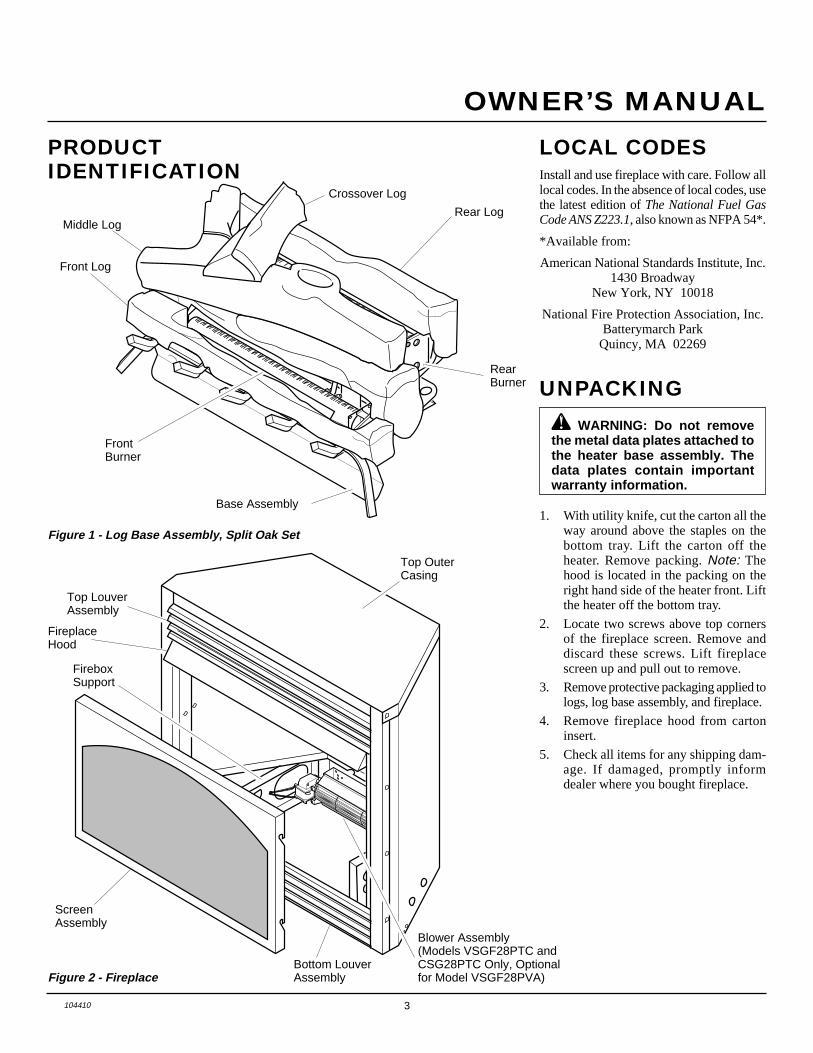
PRODUCTIDENTIFICATION
Figure 1 - Log Base Assembly, Split Oak Set
Front Log
Rear Log
Base Assembly
FrontBurner
RearBurner
Crossover Log
Figure 2 - Fireplace
Top LouverAssembly
FireplaceHood
Bottom LouverAssembly
ScreenAssembly
Top OuterCasing
FireboxSupport
Blower Assembly(Models VSGF28PTC andCSG28PTC Only, Optionalfor Model VSGF28PVA)
LOCAL CODESInstall and use fireplace with care. Follow alllocal codes. In the absence of local codes, usethe latest edition of The National Fuel GasCode ANS Z223.1, also known as NFPA 54*.
*Available from:
American National Standards Institute, Inc.1430 Broadway
New York, NY 10018
National Fire Protection Association, Inc.Batterymarch ParkQuincy, MA 02269
UNPACKING
1. With utility knife, cut the carton all theway around above the staples on thebottom tray. Lift the carton off theheater. Remove packing. Note: Thehood is located in the packing on theright hand side of the heater front. Liftthe heater off the bottom tray.
2. Locate two screws above top cornersof the fireplace screen. Remove anddiscard these screws. Lift fireplacescreen up and pull out to remove.
3. Remove protective packaging applied tologs, log base assembly, and fireplace.
4. Remove fireplace hood from cartoninsert.
5. Check all items for any shipping dam-age. If damaged, promptly informdealer where you bought fireplace.
Middle Log
WARNING: Do not removethe metal data plates attached tothe heater base assembly. Thedata plates contain importantwarranty information.

4 104410
UNVENTED PROPANE/LP GAS FIREPLACE
DESA INTERNATIONAL
AIR FORCOMBUSTION ANDVENTILATION
Today’s homes are built more energy effi-cient than ever. New materials, increasedinsulation, and new construction methodshelp reduce heat loss in homes. Home ownersweather strip and caulk around windows anddoors to keep the cold air out and the warm airin. During heating months, home ownerswant their homes as airtight as possible.While it is good to make your home energyefficient, your home needs to breathe. Freshair must enter your home. All fuel-burningappliances need fresh air for proper com-bustion and ventilation.Exhaust fans, fireplaces, clothes dryers, andfuel burning appliances draw air from thehouse to operate. You must provide ad-equate fresh air for these appliances. Thiswill insure proper venting of vented fuel-burning appliances.
Confined Space and UnconfinedSpaceThe National Fuel Gas Code (ANS Z223.1,1992 Section 5.3) defines a confined spaceas a space whose volume is less than 50cubic feet per 1,000 Btu per hour (4.8 m3 perkw) of the aggregate input rating of allappliances installed in that space and anunconfined space as a space whose volumeis not less than 50 cubic feet per 1,000 Btuper hour (4.8 m3 per kw) of the aggregateinput rating of all appliances installed in thatspace. Rooms communicating directly withthe space in which the appliances are in-stalled*, through openings not furnishedwith doors, are considered a part of theunconfined space.
This heater shall not be installed in a con-fined space or unusually tight constructionunless provisions are provided for adequatecombustion and ventilation air.
* Adjoining rooms are communicating onlyif there are doorless passageways or ventila-tion grills between them.
PROVIDING ADEQUATEVENTILATIONThe following are excerpt from NationalFuel Gas Code. NFPA 54/ANS Z223.1, Sec-tion 5.3, Air for Combustion and Ventilation.
All spaces in homes fall into one of the threefollowing ventilation classifications:
1. Unusually Tight Construction2. Unconfined Space3. Confined SpaceThe information on pages 4 through 6 willhelp you classify your space and provideadequate ventilation.
Unusually Tight ConstructionThe air that leaks around doors and win-dows may provide enough fresh air for com-bustion and ventilation. However, in build-ings of unusually tight construction, youmust provide additional fresh air.
PRODUCTFEATURESOPERATIONThis vent-free fireplace is clean burning. Itrequires no outside venting. There is no heatloss out a vent or up a chimney. Heat isgenerated by both realistic flames and glow-ing embers. When used without the blower,the fireplace requires no electricity makingit ideal for emergency backup heat.
SAFETY DEVICEThis fireplace has a pilot with an OxygenDetection Safety Pilot System (ODS). TheODS/pilot is a required feature for vent-freeroom heaters. The ODS system shuts off thefireplace if there is not enough fresh air.
PIEZO IGNITION SYSTEMThis fireplace has a piezo ignitor. This sys-tem requires no matches, batteries, or othersources to light fireplace.
BLOWER ASSEMBLY(VSGF28PTC/CSGF28PTC)This fireplace has a blower assembly. Theblower operates thermostatically. Theblower circulates heated air from thefireplace into the room. Use of blower isoptional. Optional blower accessories areavailable for models VSGF28PVA.
THERMOSTAT CONTROLMODELS(VSGF28PTC/CSGF28PTC)These fireplaces have a thermostat sensingbulb and a control valve. The thermostat con-trols the heat output and flame height. Thismaintains a consistent room temperature. Eventhe lowest setting provides realistic flames andglowing embers from two burners. Selectinghigher comfort settings allows fireplace to runlonger, producing greater heat output. At lowercomfort settings, the fireplace will run less.This results in increased heating comfort. Thiscan also result in lower gas bills.
VARIABLE MANUALCONTROL (VSGF28PVA)These fireplaces have a variable manualcontrol valve which allows the user to choosethe heat setting that best suits his needs. Anysetting between low and high may be se-lected by simply turning the control knob.
WARNING: This heater shallnot be installed in a confined spaceor unusually tight constructionunless provisions are providedfor adequate combustion and ven-tilation air. Read the following in-structions to insure proper freshair for this and other fuel-burningappliances in your home.
Unusually tight construction is de-fined as construction where:a. walls and ceilings exposed to the
outside atmosphere have a con-tinuous water vapor retarder witha rating of one perm (6 x 10 -11 kgper pa-sec-m 2) or less with open-ings gasketed or sealed and
b. weather stripping has beenadded on openable windows anddoors and
c. caulking or sealants are appliedto areas such as joints aroundwindow and door frames, be-tween sole plates and floors, be-tween wall-ceiling joints, be-tween wall panels, at penetra-tions for plumbing, electrical, andgas lines, and at other openings.
If your home meets all of the threecriteria above, you must provide ad-ditional fresh air. See Ventilation AirFrom Outdoors , page 6 .If your home does not meet all of thethree criteria above, proceed to Deter-mining Fresh-Air Flow for FireplaceLocation on page 5.
5104410
OWNER’S MANUAL
AIR FORCOMBUSTION ANDVENTILATIONContinued
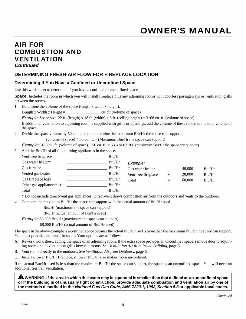
DETERMINING FRESH-AIR FLOW FOR FIREPLACE LOCATION
Determining if You Have a Confined or Unconfined Space
Use this work sheet to determine if you have a confined or unconfined space.
Space: Includes the room in which you will install fireplace plus any adjoining rooms with doorless passageways or ventilation grillsbetween the rooms.
1. Determine the volume of the space (length x width x height).
Length x Width x Height = _________________cu. ft. (volume of space)
Example: Space size 22 ft. (length) x 18 ft. (width) x 8 ft. (ceiling height) = 3168 cu. ft. (volume of space)
If additional ventilation to adjoining room is supplied with grills or openings, add the volume of these rooms to the total volume ofthe space.
2. Divide the space volume by 50 cubic feet to determine the maximum Btu/Hr the space can support.
___________ (volume of space) ÷ 50 cu. ft. = (Maximum Btu/Hr the space can support)
Example: 3168 cu. ft. (volume of space) ÷ 50 cu. ft. = 63.3 or 63,300 (maximum Btu/Hr the space can support)
3. Add the Btu/Hr of all fuel burning appliances in the space.
Vent-free fireplace ____________________ Btu/Hr
Gas water heater* ____________________ Btu/Hr
Gas furnace ____________________ Btu/Hr
Vented gas heater ____________________ Btu/Hr
Gas fireplace logs ____________________ Btu/Hr
Other gas appliances* + ____________________ Btu/Hr
Total = ____________________ Btu/Hr
* Do not include direct-vent gas appliances. Direct-vent draws combustion air from the outdoors and vents to the outdoors.
4. Compare the maximum Btu/Hr the space can support with the actual amount of Btu/Hr used.
_________ Btu/Hr (maximum the space can support)
_________ Btu/Hr (actual amount of Btu/Hr used)
Example: 63,300 Btu/Hr (maximum the space can support)
68,000 Btu/Hr (actual amount of Btu/Hr used)
The space in the above example is a confined space because the actual Btu/Hr used is more than the maximum Btu/Hr the space can support.You must provide additional fresh air. Your options are as follows:
A. Rework work sheet, adding the space of an adjoining room. If the extra space provides an unconfined space, remove door to adjoin-ing room or add ventilation grills between rooms. See Ventilation Air from Inside Building, page 6.
B. Vent room directly to the outdoors. See Ventilation Air from Outdoors, page 6.
C. Install a lower Btu/Hr fireplace, if lower Btu/Hr size makes room unconfined.
If the actual Btu/Hr used is less than the maximum Btu/Hr the space can support, the space is an unconfined space. You will need noadditional fresh air ventilation.
Continued
WARNING: If the area in which the heater may be operated is smaller than that defined as an unconfined spaceor if the building is of unusually tight construction, provide adequate combustion and ventilation air by one ofthe methods described in the National Fuel Gas Code, ANS Z223.1, 1992, Section 5.3 or applicable local codes.
Example:Gas water heater 40,000 Btu/Hr
Vent-free fireplace + 28,000 Btu/Hr
Total = 68,000 Btu/Hr
6 104410
UNVENTED PROPANE/LP GAS FIREPLACE
DESA INTERNATIONAL
AIR FORCOMBUSTION ANDVENTILATIONContinued
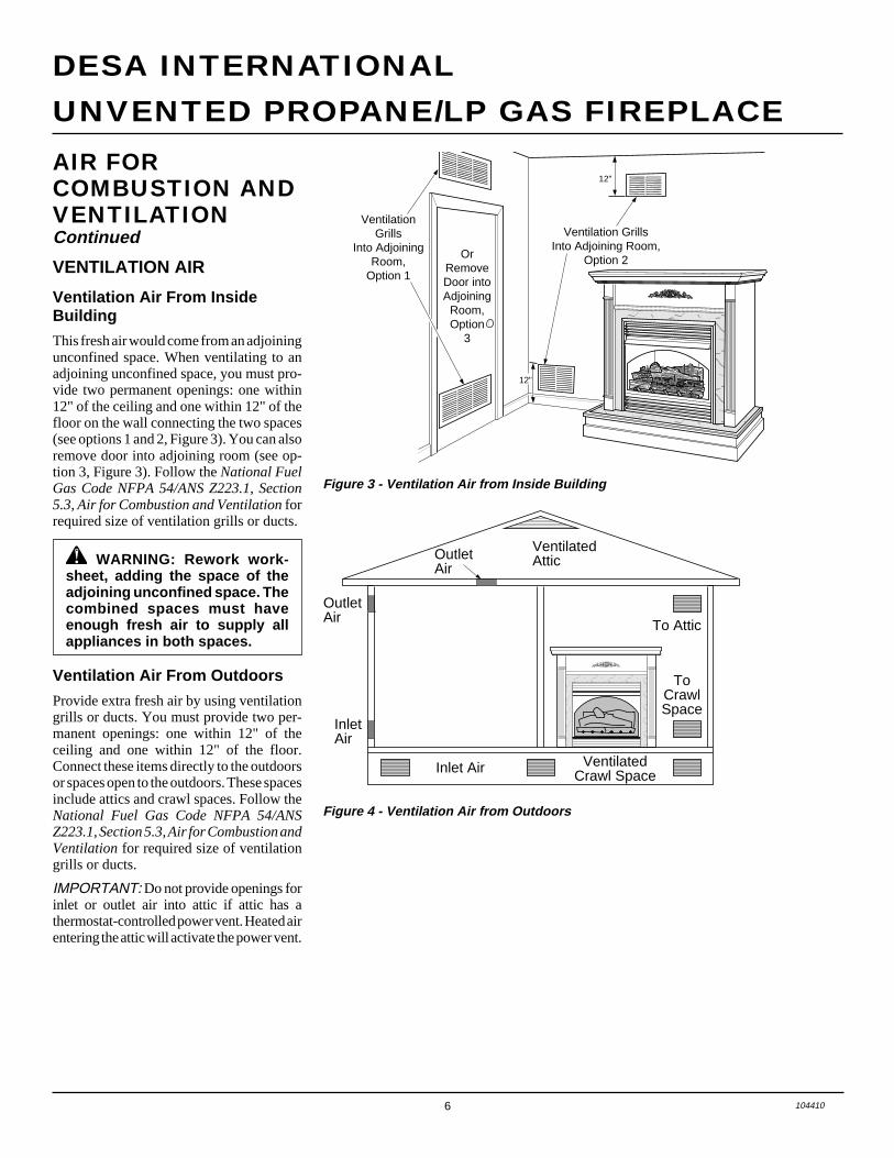
VENTILATION AIR
Ventilation Air From InsideBuilding
This fresh air would come from an adjoiningunconfined space. When ventilating to anadjoining unconfined space, you must pro-vide two permanent openings: one within12" of the ceiling and one within 12" of thefloor on the wall connecting the two spaces(see options 1 and 2, Figure 3). You can alsoremove door into adjoining room (see op-tion 3, Figure 3). Follow the National FuelGas Code NFPA 54/ANS Z223.1, Section5.3, Air for Combustion and Ventilation forrequired size of ventilation grills or ducts.
Figure 4 - Ventilation Air from Outdoors
Ventilation Air From Outdoors
Provide extra fresh air by using ventilationgrills or ducts. You must provide two per-manent openings: one within 12" of theceiling and one within 12" of the floor.Connect these items directly to the outdoorsor spaces open to the outdoors. These spacesinclude attics and crawl spaces. Follow theNational Fuel Gas Code NFPA 54/ANSZ223.1, Section 5.3, Air for Combustion andVentilation for required size of ventilationgrills or ducts.
IMPORTANT: Do not provide openings forinlet or outlet air into attic if attic has athermostat-controlled power vent. Heated airentering the attic will activate the power vent.
Figure 3 - Ventilation Air from Inside Building
OutletAir
VentilatedAttic
OutletAir
InletAir
Inlet Air Ventilated Crawl Space
To CrawlSpace
To Attic
������������������������������������������
QQQQQQQQQQQQQQQQQQQQQQQQQQQQQQQQQQQQQQQQQQ
¢¢¢¢¢¢¢¢¢¢¢¢¢¢¢¢¢¢¢¢¢¢¢¢¢¢¢¢¢¢¢¢¢¢¢¢¢¢¢¢¢¢
����������������
QQQQQQQQQQQQQQQQ
¢¢¢¢¢¢¢¢¢¢¢¢¢¢¢¢
����QQQQ¢¢¢¢
����������QQQQQQQQQQ¢¢¢¢¢¢¢¢¢¢
OrRemoveDoor intoAdjoining
Room,Option
3
Ventilation Grills Into Adjoining Room,
Option 2
VentilationGrills
Into Adjoining Room,
Option 1
12"
12"
WARNING: Rework work-sheet, adding the space of theadjoining unconfined space. Thecombined spaces must haveenough fresh air to supply allappliances in both spaces.

7104410
OWNER’S MANUAL
INSTALLATION
Continued
Note: Your fireplace is designed to be usedin zero clearance installations. Wall or fram-ing material can be placed directly againstany exterior surface on the rear, sides, or topof your fireplace, except where standoffspacers are integrally attached. If standoffspacers are attached to your fireplace, thesespacers can be placed directly against wallor framing materials.
Use the dimensions shown for rough open-ings to create the easiest installation (seeBuilt-In Fireplace Installation, page 13).
IMPORTANT: Vent-free heaters add mois-ture to the air. Although this is beneficial,installing fireplace in rooms without enoughventilation air may cause mildew to formfrom too much moisture. See Air for Com-bustion and Ventilation, pages 4 through 6.
IMPORTANT: Make sure the fireplace islevel. If fireplace is not level, log set will notwork properly.
CHECK GAS TYPEUse only propane/LP gas. If your gas supplyis not propane/LP gas, do not install fire-place. Call dealer where you bought fire-place for proper type fireplace.
CAUTION: This fireplace cre-ates warm air currents. These cur-rents move heat to wall surfacesnext to fireplace. Installing fire-place next to vinyl or cloth wallcoverings or operating fireplacewhere impurities (such as to-bacco smoke, aromatic candles,cleaning fluids, oil or kerosenelamps, etc.) in the air exist, maydiscolor walls.
WARNING: A qualified ser-vice person must install fireplace.Follow all local codes.
WARNING: Never install thefireplace• in a bedroom or bathroom• in a recreational vehicle• where curtains, furniture,
clothing, or other flammableobjects are less than 42 inchesfrom the front, top, or sides ofthe fireplace
• in high traffic areas• in windy or drafty areas
WARNING: Models VSGF28PTC/ CSGF28PTC have a three-prong,grounded electrical plug. Thisplug helps protect you againstelectrical shock. Only connectplug to a properly grounded,three-prong receptacle. Do notcut or remove the groundingprong from this plug.
NOTICE: This heater is intendedfor use as supplemental heat.Use this heater along with yourprimary heating system. Do notinstall this heater as your pri-mary heat source. If you have acentral heating system, you mayrun system’s circulating blowerwhile using heater. This will helpcirculate the heat throughout thehouse. In the event of a poweroutage, you can use this heateras your primary heat source.
Figure 5 - Installing Hood
INSTALLING HOODInstall hood to rail already installed in fire-place as shown in Figure 5. Use 3 Phillipsscrews provided.
Screw
Hood
Rail
ELECTRICAL HOOKUP(Models VSGF28PTC/CSGF28PTC )
This fireplace has a blower assembly with anelectrical cord. The electrical cord is five feetin length. You must locate fireplace withinreach of a 120-volt grounded electrical out-let. If not, you must install an electrical outletwithin reach of fireplace power cord. Thissame information applies if installing op-tional blower accessories to ModelVSGF28PVA.

8 104410
UNVENTED PROPANE/LP GAS FIREPLACE
DESA INTERNATIONAL
INSTALLATIONContinued
Figure 7 - Attaching Brass Trim toFireplace
TrimHangingScrews
AssembledBrass Trim
HangingNotcheson Trim
INSTALLING OPTIONALBLOWER ACCESSORY (FORMODEL VSGF28PVA)The following instructions are for optionalblower accessories GA3700 and GA3700T.If you do not have this accessory and wish topurchase one, see Accessories on pages 26and 27 of this manual.
2. Place the blower against lower rear wallof firebox outer wrapper with the ex-haust port directed upward. Align theholes in top mounting tabs of blowerwith holes in wall of wrapper (see Fig-ure 9). Using 2 screws provided, mountblower and tighten screws securely.
3. Be certain that all wire terminals aresecurely attached to terminals onblower motor and that the screw retain-ing the green ground wire is tight.
4. Place control knob provided on plasticcontrol shaft of speed control.
5. Mount the speed control on the frontleg of the left floor support bracket us-ing 2 screws provided (see Figure 10).
Figure 8 - Removing Log Base fromFireplace
Figure 9 - Mounting Blower to Firebox
Figure 10 - Attaching Speed Control toFirebox
Screws
Log Base
BlowerScrews
Screws
SpeedControl
ControlKnob
FlexibleGas Line
Left FloorSupportBracket
ControlShaft
LowerRear Wallof Firebox
ExhaustPost
1. Remove screws that attach log base as-sembly to fireplace. Carefully lift up logbase assembly and remove from fire-place, taking care to pull flexible gas linethrough the access holes (see Figure 8).
CAUTION: Do not pick up logbase assembly by burners. Thiscould damage burners. Onlyhandle base by grates.
Installing Optional GA3700Blower Accessory
Figure 6 - Assembling Brass Trim
IMPORTANT: If you are recessing the fire-box in a wall, do not attach brass trim at thistime. See page 13.
Note: The instructions below show assem-bling and attaching brass trim to fireplace.1. Remove packaging from three pieces
of brass trim.2. Locate four brass screws, two adjust-
ing plates with set screws, and twoshims in the hardware packet.
3. Align shim under adjusting plate asshown in Figure 6.
4. Slide one end of adjusting plate/shimin slot on mitered edge of top brass trim(see Figure 6).
5. Slide other end of adjusting plate/shimin slot on mitered edge of side brasstrim (see Figure 6).
6. While firmly holding edges of brasstrim together, tighten both set screwson the adjusting plate with slottedscrewdriver.
7. Repeat steps 1 through 6 for other side.8. Tighten trim hanging screws (#10 x
6.25 shoulder) into holes in cabinets.Place the assembled trim onto fireplacecabinet. Align hanging notches on trimwith hanging screws on side of fire-place (see Figure 7). Push trim firmlyinto place, sliding hanging notches overhanging screws.
ASSEMBLING ANDATTACHING OPTIONALBRASS TRIM(Included with MantelAccessory)
Side BrassTrim
TopBrassTrim
Slot
Mitered EdgeSlot
Shim
Set Screws
AdjustingPlate
9104410
OWNER’S MANUAL
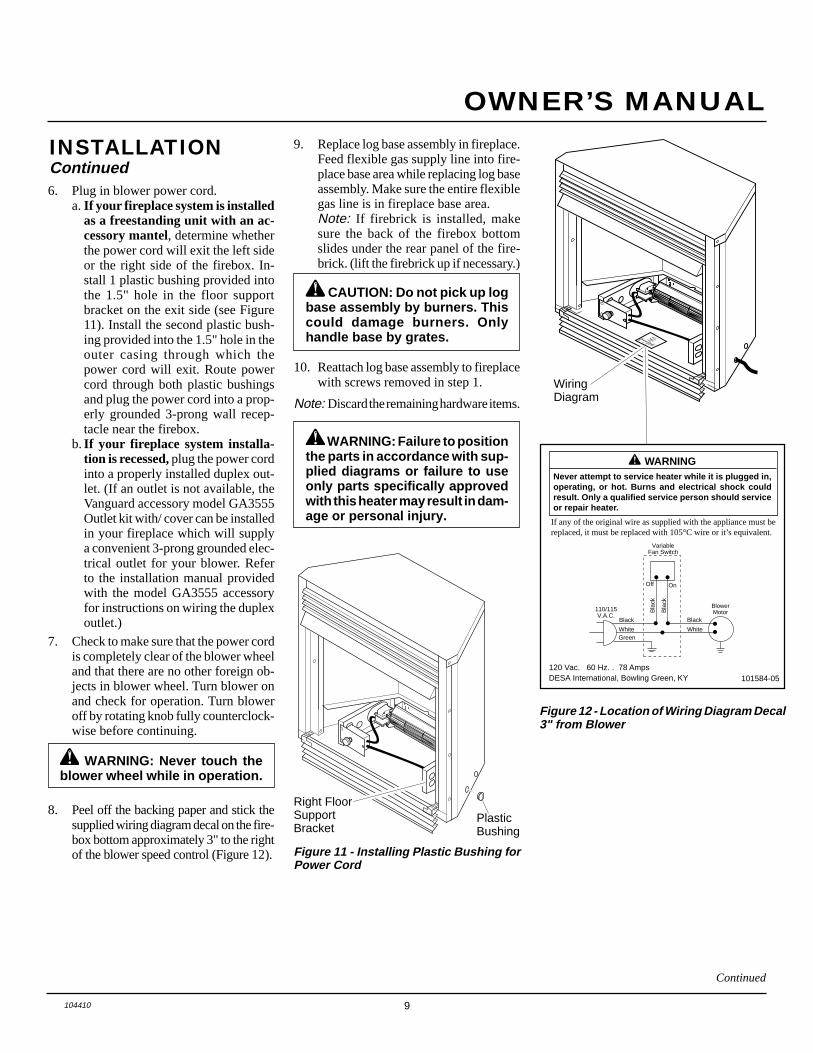
6. Plug in blower power cord.a.If your fireplace system is installed
as a freestanding unit with an ac-cessory mantel, determine whetherthe power cord will exit the left sideor the right side of the firebox. In-stall 1 plastic bushing provided intothe 1.5" hole in the floor supportbracket on the exit side (see Figure11). Install the second plastic bush-ing provided into the 1.5" hole in theouter casing through which thepower cord will exit. Route powercord through both plastic bushingsand plug the power cord into a prop-erly grounded 3-prong wall recep-tacle near the firebox.
b.If your fireplace system installa-tion is recessed, plug the power cordinto a properly installed duplex out-let. (If an outlet is not available, theVanguard accessory model GA3555Outlet kit with/ cover can be installedin your fireplace which will supplya convenient 3-prong grounded elec-trical outlet for your blower. Referto the installation manual providedwith the model GA3555 accessoryfor instructions on wiring the duplexoutlet.)
7. Check to make sure that the power cordis completely clear of the blower wheeland that there are no other foreign ob-jects in blower wheel. Turn blower onand check for operation. Turn bloweroff by rotating knob fully counterclock-wise before continuing.
WARNING: Never touch theblower wheel while in operation.
8. Peel off the backing paper and stick thesupplied wiring diagram decal on the fire-box bottom approximately 3" to the rightof the blower speed control (Figure 12). Figure 11 - Installing Plastic Bushing for
Power Cord
PlasticBushing
Right FloorSupportBracket
Variable
Fan Switch
White
White
Black
Green
On
110/115
V.A.C.
Blower
Motor
Black
Black
Black Off
Figure 12 - Location of Wiring Diagram Decal3" from Blower
WiringDiagram
WARNING ICON G 001 WARNING
Never attempt to service heater while it is plugged in,operating, or hot. Burns and electrical shock couldresult. Only a qualified service person should serviceor repair heater.
If any of the original wire as supplied with the appliance must bereplaced, it must be replaced with 105°C wire or it’s equivalent.
101584-05120 Vac. 60 Hz. . 78 AmpsDESA International, Bowling Green, KY
INSTALLATIONContinued
9. Replace log base assembly in fireplace.Feed flexible gas supply line into fire-place base area while replacing log baseassembly. Make sure the entire flexiblegas line is in fireplace base area.Note: If firebrick is installed, makesure the back of the firebox bottomslides under the rear panel of the fire-brick. (lift the firebrick up if necessary.)
CAUTION: Do not pick up logbase assembly by burners. Thiscould damage burners. Onlyhandle base by grates.
VariableFan Switch
WhiteWhite
Black
Green
On
110/115 V.A.C.
BlowerMotor
Black
Bla
ck
Bla
ck
Off
10. Reattach log base assembly to fireplacewith screws removed in step 1.
Note: Discard the remaining hardware items.
WARNING: Failure to positionthe parts in accordance with sup-plied diagrams or failure to useonly parts specifically approvedwith this heater may result in dam-age or personal injury.
Continued

10 104410
UNVENTED PROPANE/LP GAS FIREPLACE
DESA INTERNATIONAL
AUTOOFF
ON
321
1. Remove screws that attach log base as-sembly to fireplace (do not discard).Carefully lift up log base assembly andremove from fireplace, taking care topull flexible gas line through the ac-cess holes (see Figure 13).
CAUTION: Do not pick up logbase assembly by burners. Thiscould damage burners. Onlyhandle base by grates.
2. Place the blower against lower rear wallof firebox outer wrapper with the ex-haust port directed upward. Align theholes in top mounting tabs of blowerwith holes in wall of wrapper (see Fig-ure 14). Using two #8 screws provided,mount blower and tighten screwsfirmly.
3. Route terminals end of power cordthrough large hole near top of left floorsupport bracket. Make sure to pass thecord from the outside (left side) towardsthe center of firebox (see Figure 15).
4. Using two #6 screws provided attachpower cord mounting plate to the out-side face of left floor support bracket.Drive screws from inside (right side)of floor support bracket. Attach theplate so that the power cord is directedtowards rear of firebox (see Figure 15).Tighten screws firmly.
5. Remove the three screws (do not dis-card) and cover plate from center offirebox wrapper rear wall. Discard thiscover plate.
6. Mount the supplied thermostatic switchand cover assembly into firebox wrap-per wall. Do this by feeding terminalends of wire harness into the hole. Al-low wires to fall to bottom of fireboxcavity (see Figure 16).
7. Using three screws from step 5, attachswitch and cover assembly to fireboxwrapper rear wall. Tighten screwsfirmly (see Figure 16).
Figure 14 - Mounting Blower to Firebox
Figure 15 - Installing Power Cord,Mounting Plate, and Selector switch
Figure 16 - Installing Switch and CoverAssembly
Figure 13 - Removing Log Base fromFireplace
8. Mount selector switch to front flangeof left floor support bracket. Aligngraphics on switch upright and pushfirmly to snap switch into rectangularhole. Push the selector switch to the off(middle) position (see Figure 15).
9. Install three plastic wire clips providedinto floor support bracket (see Figure 15).Secure by pushing clips firmly into holes.
WARNING: Failure to connectall wires properly as indicatedmay cause electrical short circuitor personal injury. A qualifiedelectrician should check that allconnections are made properly.
10. Attach green ground wire ring termi-nal to floor support bracket using #10sheet metal grounding screw provided(see Figure 15). Tighten screw firmly.
11. Attach all five remaining wiring termi-nals to the appropriate switch or motorterminal. Carefully note the correctcolor coding (see Figures 17 and 19,page 11). Push female wire terminalsfully onto male terminal.
12. Secure wires into the appropriate plas-tic wire clips (see Figure 17, page 11).
INSTALLATIONContinued
Installing Optional GA3700TBlower Accessory
Screws
Log Base
FlexibleGas Line
Blower#8 Screws
Exhaust Port
Lower RearWall ofFirebox OuterWrapper
#6 Screws #10 Screw
WireClips
SelectorSwitch
Switch andCoverAssembly
Floor Support Bracket

11104410
OWNER’S MANUAL
AUTOOFF
ON
321
Figure 17 - Wire Attachment
Figure 18 - Installing Bushings
Bushing Locationfor RecessedInstallation
BushingLocation forFreestandingInstallation
BlueWire
Red Wire
GreenWire
Black Wire
WhiteWire
BlueWire
To Switch andCover Assembly
Note: To prevent shortcircuit, white wire MUSTbe connected to motor.
15. Peel off the backing paper and stick thesupplied wiring diagram decal on thefirebox bottom approximately 12" infront of blower.
Note: If any of the original wire as suppliedwith the appliance must be replaced, it mustbe replaced with 105˚C wire or it's equivalent.
WARNING: Failure to posi-tion the parts in accordance withsupplied diagrams or failure touse only parts specifically ap-proved with this heater may re-sult in damage or personal injury.
Figure 19 - Wiring Diagram
Blue
Blue
Fan Switch(Off/On/Auto)
Red FanSwitch(N.O.)
GreenWhite
On
110/115 V.A.C.
BlowerMotor
Black
Off
12
3
Auto
INSTALLATIONContinued
16. Replace log base assembly in fireplace.Feed flexible gas supply line into fire-place base area while replacing log baseassembly. Make sure the entire flexiblegas line is in fireplace base area.
Note: If firebrick is installed, make surethe back of the firebox bottom slidesunder the rear panel of the firebrick (liftthe firebrick up if necessary.
IMPORTANT: Do not pick uplog base assembly by burners.This could damage burners. Onlyhandle base by grates.
17. Reattach log base assembly to fireplacewith screws removed in step 1, page 10.
Continued
13. Plug in blower power cord.
If your fireplace system is installedas a freestanding unit with an acces-sory mantel, install one plastic bush-ing (provided) into the 1.5" hole in thelower left side of the outer casing (seeFigure 18). Route power cord throughplastic bushing. Plug the power cordinto a properly grounded three-prongwall receptacle near the firebox.
If your fireplace system installationis recessed, install one plastic bushingprovided into the 1.5" hole near themiddle of the left floor support bracket(see Figure 18). Route power cordthrough plastic bushing. Plug the powercord into a properly installed duplexoutlet. (If an outlet is not available, theaccessory model GA3555 Outlet Kitwith cover can be installed in your fire-place. This will supply a convenientthree-prong grounded electrical outletfor your blower. Refer to the installa-tion manual provided with the modelGA3555 accessory for instructions onwiring the duplex outlet.)
14. Check to make sure that the power cordand wires are completely clear of theblower wheel and that there are no otherforeign objects in blower wheel. Turnblower on by pushing the selector switchto the on position and check for opera-tion. Turn blower off before continuing.
WARNING: Never touch theblower wheel while in operation.
12 104410
UNVENTED PROPANE/LP GAS FIREPLACE
DESA INTERNATIONAL
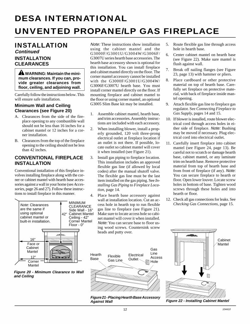
Figure 22 - Installing Cabinet Mantel
����������QQQQQQQQQQ¢¢¢¢¢¢¢¢¢¢
��������������������
QQQQQQQQQQQQQQQQQQQQ
¢¢¢¢¢¢¢¢¢¢¢¢¢¢¢¢¢¢¢¢
����������QQQQQQQQQQ¢¢¢¢¢¢¢¢¢¢
ElectricalOutlet
HearthBase
FlexibleGas Line
GasLineAccessHole
CabinetMantel
5. Route flexible gas line through accesshole in hearth base.
6. Center cabinet mantel on hearth base(see Figure 22). Make sure mantel isflush against wall.
7. Break off nailing flanges (see Figure23, page 13) with hammer or pliers.
8. Place cardboard or other protectivematerial on top of hearth base. Care-fully set fireplace on protective mate-rial, with back of fireplace inside man-tel opening.
9. Attach flexible gas line to fireplace gasregulator. See Connecting Fireplace toGas Supply, pages 14 and 15.
10. If blower is installed, route blower elec-trical cord through access holes in ei-ther side of fireplace. Note: Bushingmay be moved if necessary. Plug elec-trical cord into electrical outlet.
11. Carefully insert fireplace into cabinetmantel (see Figure 24, page 13). Becareful not to scratch or damage hearthbase, cabinet mantel, or any laminatetrim on hearth base. Remove protectivematerial from top of hearth base andfrom front of fireplace (if any). Note:You can secure fireplace to hearth orfloor. Open lower louver. Locate screwholes in bottom of base. Tighten woodscrews through these holes and intohearth or floor.
12. Check all gas connections for leaks. SeeChecking Gas Connections, page 15.
INSTALLATIONCLEARANCES
WARNING: Maintain the mini-mum clearances. If you can, pro-vide greater clearances fromfloor, ceiling, and adjoining wall.
Carefully follow the instructions below. Thiswill ensure safe installation.
Minimum Wall and CeilingClearances (see Figure 20)A. Clearances from the side of the fire-
place opening to any combustible wallshould not be less than 16 inches for acabinet mantel or 12 inches for a cor-ner installation.
B. Clearances from the top of the fireplaceopening to the ceiling should not be lessthan 42 inches.
CONVENTIONAL FIREPLACEINSTALLATIONConventional installation of this fireplace in-volves installing fireplace along with the cor-ner or cabinet mantel with hearth base acces-sories against a wall in your home (see Acces-sories, page 26 and 27). Follow these instruc-tions to install fireplace in this manner.
1. Assemble cabinet mantel, hearth base,and trim accessories. Assembly instruc-tions are included with each accessory.
2. When installing blower, install a prop-erly grounded, 120 volt three-prongelectrical outlet at fireplace location ifan outlet is not there. If possible, lo-cate outlet so cabinet mantel will coverit when installed (see Figure 21).
3. Install gas piping to fireplace location.This installation includes an approvedflexible gas line (if allowed by localcodes) after the manual shutoff valve.The flexible gas line must be the lastitem installed on the gas piping. See In-stalling Gas Piping to Fireplace Loca-tion, page 14.
4. Place hearth base accessory againstwall at installation location. Cut an ac-cess hole in hearth top to run flexiblegas line to fireplace (see Figure 21).Make sure to locate access hole so cabi-net mantel will cover it when installed.Note: You can secure base to floor us-ing wood screws. Countersink screwheads and putty over.
Figure 20 - Minimum Clearance to Walland Ceiling
INSTALLATIONContinued
�������������������������
QQQQQQQQQQQQQQQQQQQQQQQQQ
¢¢¢¢¢¢¢¢¢¢¢¢¢¢¢¢¢¢¢¢¢¢¢¢¢
42"
16"Face or
Cabinet Mantel
CornerMantel
12"
Note: Clearancesare the same ifusing optionalcabinet mantel orbuilt-in installation.
Note: These instructions show installationusing the cabinet mantel and theG3000F/G3001U/G3004W/G3006F/G3007U series hearth base accessories. Thehearth base accessory shown is optional forthis installation. You can install fireplaceand cabinet mantel directly on the floor. Thecorner mantel accessory cannot be installedwith the G3000F/G3001U/G3004W/G3006F/G3007U hearth base. You mustinstall corner mantel directly on the floor. Ifmounting fireplace and cabinet mantel tothe floor or using corner mantel, an optionalG3005 Slim Base kit may be installed.
Figure 21 - Placing Hearth Base AccessoryAgainst Wall
MINIMUMCLEARANCESide Wall - 16"Cabinet MantelCeiling - 42"Corner MantelFloor - 0"
13104410
OWNER’S MANUAL
INSTALLATIONContinued
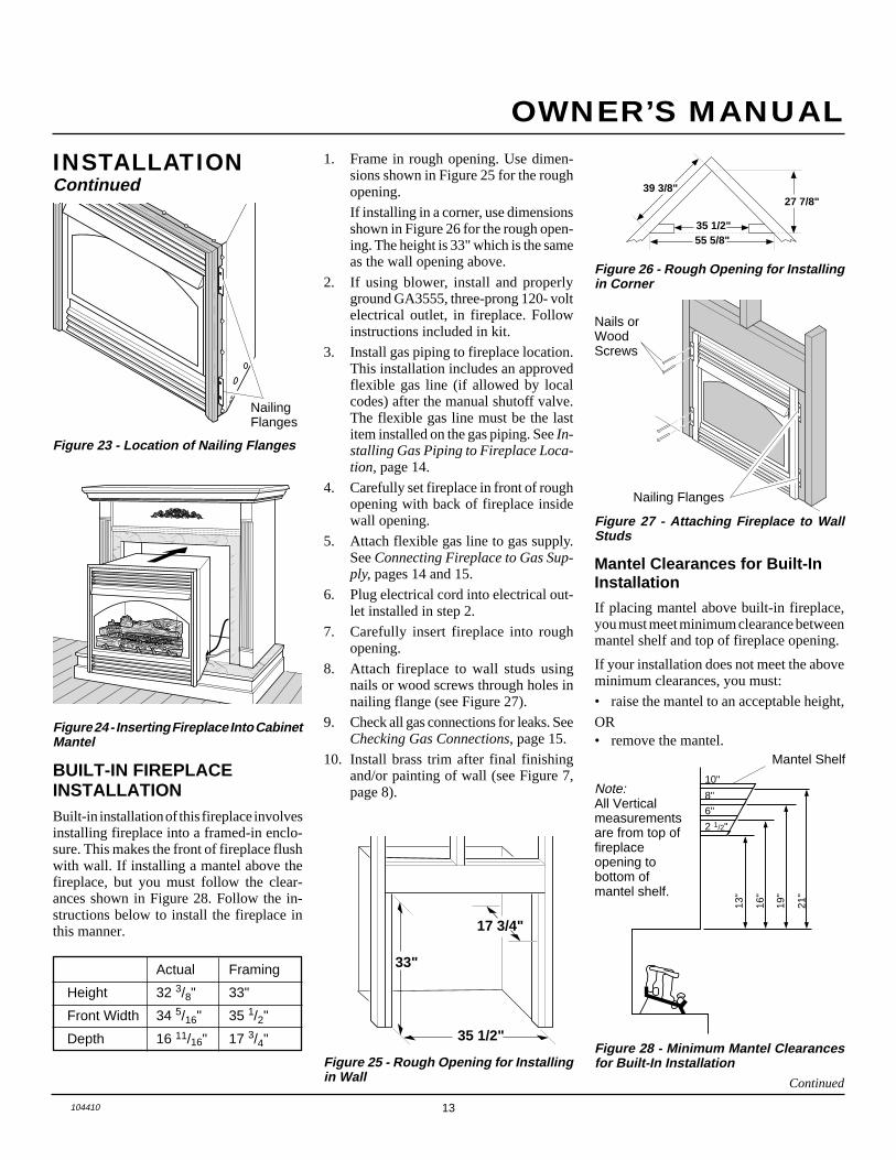
Figure 24 - Inserting Fireplace Into CabinetMantel
����������QQQQQQQQQQ¢¢¢¢¢¢¢¢¢¢���������������
QQQQQQQQQQQQQQQ
¢¢¢¢¢¢¢¢¢¢¢¢¢¢¢
Figure 23 - Location of Nailing Flanges
Continued
Actual Framing
Height 32 3/8" 33"
Front Width 34 5/16" 35 1/2"
Depth 16 11/16" 17 3/4" 35 1/2"
17 3/4"
33"
Figure 25 - Rough Opening for Installingin Wall
BUILT-IN FIREPLACEINSTALLATIONBuilt-in installation of this fireplace involvesinstalling fireplace into a framed-in enclo-sure. This makes the front of fireplace flushwith wall. If installing a mantel above thefireplace, but you must follow the clear-ances shown in Figure 28. Follow the in-structions below to install the fireplace inthis manner.
Figure 27 - Attaching Fireplace to WallStuds
39 3/8"27 7/8"
55 5/8" 35 1/2"
Figure 26 - Rough Opening for Installingin Corner
1. Frame in rough opening. Use dimen-sions shown in Figure 25 for the roughopening.
If installing in a corner, use dimensionsshown in Figure 26 for the rough open-ing. The height is 33" which is the sameas the wall opening above.
2. If using blower, install and properlyground GA3555, three-prong 120- voltelectrical outlet, in fireplace. Followinstructions included in kit.
3. Install gas piping to fireplace location.This installation includes an approvedflexible gas line (if allowed by localcodes) after the manual shutoff valve.The flexible gas line must be the lastitem installed on the gas piping. See In-stalling Gas Piping to Fireplace Loca-tion, page 14.
4. Carefully set fireplace in front of roughopening with back of fireplace insidewall opening.
5. Attach flexible gas line to gas supply.See Connecting Fireplace to Gas Sup-ply, pages 14 and 15.
6. Plug electrical cord into electrical out-let installed in step 2.
7. Carefully insert fireplace into roughopening.
8. Attach fireplace to wall studs usingnails or wood screws through holes innailing flange (see Figure 27).
9. Check all gas connections for leaks. SeeChecking Gas Connections, page 15.
10. Install brass trim after final finishingand/or painting of wall (see Figure 7,page 8).
Mantel Clearances for Built-InInstallation
If placing mantel above built-in fireplace,you must meet minimum clearance betweenmantel shelf and top of fireplace opening.
If your installation does not meet the aboveminimum clearances, you must:
• raise the mantel to an acceptable height,
OR• remove the mantel.
Nailing Flanges
Nails orWoodScrews
Figure 28 - Minimum Mantel Clearancesfor Built-In Installation
Mantel Shelf
13"
16"
19"
21"
2 1/2"
6"
8"
10"Note:All Verticalmeasurementsare from top offireplaceopening tobottom ofmantel shelf.
NailingFlanges

14 104410
UNVENTED PROPANE/LP GAS FIREPLACE
DESA INTERNATIONAL
CAUTION: Do not pick up logbase assembly by burners. Thiscould damage burners. Onlyhandle base by grates.
Installation Items Needed• 5/16" hex socket wrench or nut-driver
• Phillips screwdriver
• sealant (resistant to propane/LP gas, notprovided)
1. Remove fireplace screen. Remove twoscrews that hold fireplace screen inplace for shipping. These screws arelocated near top of screen. Discardscrews. Lift fireplace screen up and pullout to remove.
2. Remove screws that attach log baseassembly to fireplace (see Figure 31).Carefully lift up log base assembly andremove from fireplace (see Figure 31).
Note: If adding the G8000 series brick lineraccessory, install it now. Follow instruc-tions in G8000 accessory kit.
CONNECTING FIREPLACETO GAS SUPPLY
3. Route flexible gas line (provided byinstaller) from manual shutoff valve tofireplace. Route flexible gas supply linethrough one of the access holes.
A.G.A. Design-CertifiedManual Shutoff Valvewith 1/8" NPT Tap*
3" Minimum
FromExternalRegulator(11" W.C.to 14" W.C.Pressure)
Approved FlexibleGas Line
Pipe Cap TeeNipple Joint
Sediment Trap
Figure 30 - Gas Connection
* Purchase the optional A.G.A. design-cer-tified manual shutoff valve from your dealer.See Accessories, pages 26 and 27.
CAUTION: Use only new,black iron or steel pipe. Inter-nally-tinned copper tubing maybe used in certain areas. Checkyour local codes. Use pipe of 1/2"diameter or greater to allowproper gas volume to fireplace. Ifpipe is too small, undue loss ofpressure will occur.
Installation must include a manual shutoffvalve, union, and plugged 1/8" NPT tap.Locate NPT tap within reach for test gaugehook up. NPT tap must be upstream fromfireplace (see Figure 30).
Check your building codes for any specialrequirements for locating manual shutoffvalve to fireplaces.
The installer must supply an external regu-lator. The external regulator will reduceincoming gas pressure. You must reduceincoming gas pressure to between 11 and 14inches of water. If you do not reduce incom-ing gas pressure, heater regulator damagecould occur. Install external regulator withthe vent pointing down as shown in Figure29. Pointing the vent down protects it fromfreezing rain or sleet.
INSTALLATIONContinued
INSTALLING GAS PIPING TOFIREPLACE LOCATION
Installation Items Needed
Before installing fireplace, make sure youhave the items listed below.
• external regulator (supplied by installer)
• piping (check local codes)
• sealant (resistant to propane/LP gas)
• manual shutoff valve *
• test gauge connection *
• sediment trap
• tee joint
• pipe wrench
• approved flexible gas line with gas con-nector (if allowed by local codes) (notprovided)
* An A.G.A. design-certified manual shutoffvalve with 1/8" NPT tap is an acceptablealternative to test gauge connection. Pur-chase the optional A.G.A. design-certifiedmanual shutoff valve from your dealer. SeeAccessories, pages 26 and 27.
WARNING: A qualified ser-vice person must connect fire-place to gas supply. Follow alllocal codes.
CAUTION: Never connectheater directly to the propane/LPsupply. This heater requires anexternal regulator (not supplied).Install the external regulator be-tween the heater and propane/LPsupply.
CAUTION: Use pipe joint seal-ant that is resistant to liquid pe-troleum (LP) gas.
Figure 29 - External Regulator with VentPointing Down
Propane/LP SupplyTank
ExternalRegulator
VentPointingDown
We recommend that you install a sedimenttrap in supply line as shown in Figure 30.Locate sediment trap where it is withinreach for cleaning. Install in piping systembetween fuel supply and heater. Locate sedi-ment trap where trapped matter is not likelyto freeze. A sediment trap traps moistureand contaminants. This keeps them fromgoing into fireplace gas controls. If sedi-ment trap is not installed or is installedwrong, fireplace may not run properly.
Apply pipe joint sealant lightly to malethreads. This will prevent excess sealantfrom going into pipe. Excess sealant in pipecould result in clogged fireplace valves.
15104410
OWNER’S MANUAL
��������������������������������������������������������������������������������������������������������������
QQQQQQQQQQQQQQQQQQQQQQQQQQQQQQQQQQQQQQQQQQQQQQQQQQQQQQQQQQQQQQQQQQQQQQQQQQQQQQQQQQQQQQQQQQQQQQQQQQQQQQQQQQQQQQ
¢¢¢¢¢¢¢¢¢¢¢¢¢¢¢¢¢¢¢¢¢¢¢¢¢¢¢¢¢¢¢¢¢¢¢¢¢¢¢¢¢¢¢¢¢¢¢¢¢¢¢¢¢¢¢¢¢¢¢¢¢¢¢¢¢¢¢¢¢¢¢¢¢¢¢¢¢¢¢¢¢¢¢¢¢¢¢¢¢¢¢¢¢¢¢¢¢¢¢¢¢¢¢¢¢¢¢¢¢¢
ManualShutoff Valve
ManualGas Valve
Propane/LPSupply Tank
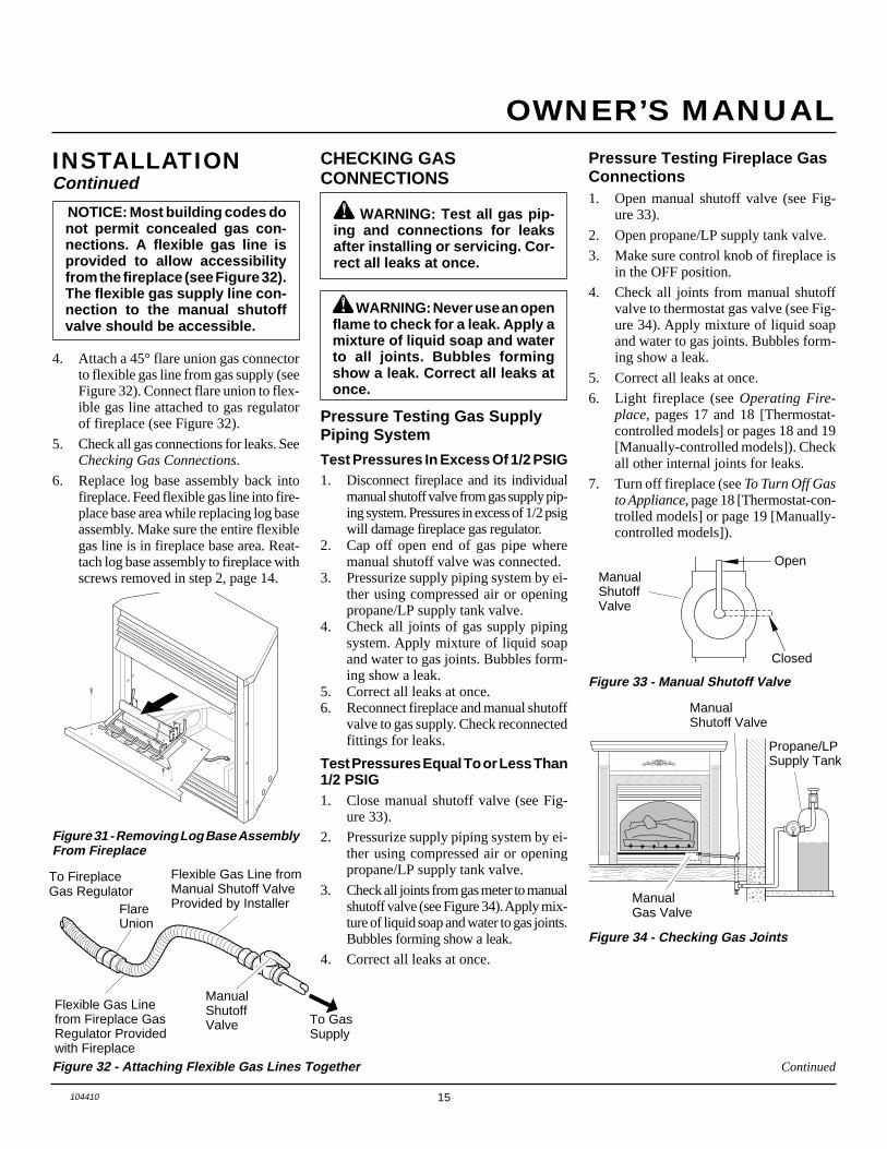
Pressure Testing Gas SupplyPiping System
Test Pressures In Excess Of 1/2 PSIG1. Disconnect fireplace and its individual
manual shutoff valve from gas supply pip-ing system. Pressures in excess of 1/2 psigwill damage fireplace gas regulator.
2. Cap off open end of gas pipe wheremanual shutoff valve was connected.
3. Pressurize supply piping system by ei-ther using compressed air or openingpropane/LP supply tank valve.
4. Check all joints of gas supply pipingsystem. Apply mixture of liquid soapand water to gas joints. Bubbles form-ing show a leak.
5. Correct all leaks at once.6. Reconnect fireplace and manual shutoff
valve to gas supply. Check reconnectedfittings for leaks.
CHECKING GASCONNECTIONS
WARNING: Test all gas pip-ing and connections for leaksafter installing or servicing. Cor-rect all leaks at once.
WARNING: Never use an openflame to check for a leak. Apply amixture of liquid soap and waterto all joints. Bubbles formingshow a leak. Correct all leaks atonce.
Figure 31 - Removing Log Base AssemblyFrom Fireplace
INSTALLATIONContinued
Figure 32 - Attaching Flexible Gas Lines Together
NOTICE: Most building codes donot permit concealed gas con-nections. A flexible gas line isprovided to allow accessibilityfrom the fireplace (see Figure 32).The flexible gas supply line con-nection to the manual shutoffvalve should be accessible.
4. Attach a 45° flare union gas connectorto flexible gas line from gas supply (seeFigure 32). Connect flare union to flex-ible gas line attached to gas regulatorof fireplace (see Figure 32).
5. Check all gas connections for leaks. SeeChecking Gas Connections.
6. Replace log base assembly back intofireplace. Feed flexible gas line into fire-place base area while replacing log baseassembly. Make sure the entire flexiblegas line is in fireplace base area. Reat-tach log base assembly to fireplace withscrews removed in step 2, page 14.
Continued
Flexible Gas Linefrom Fireplace GasRegulator Providedwith Fireplace
To FireplaceGas Regulator
FlareUnion
Flexible Gas Line fromManual Shutoff ValveProvided by Installer
ManualShutoffValve
➞To GasSupply
Test Pressures Equal To or Less Than1/2 PSIG1. Close manual shutoff valve (see Fig-
ure 33).
2. Pressurize supply piping system by ei-ther using compressed air or openingpropane/LP supply tank valve.
3. Check all joints from gas meter to manualshutoff valve (see Figure 34). Apply mix-ture of liquid soap and water to gas joints.Bubbles forming show a leak.
4. Correct all leaks at once.
Figure 33 - Manual Shutoff Valve
ONPOSITION
OFFPOSITION
Open
Closed
ManualShutoffValve
Figure 34 - Checking Gas Joints
Pressure Testing Fireplace GasConnections1. Open manual shutoff valve (see Fig-
ure 33).
2. Open propane/LP supply tank valve.
3. Make sure control knob of fireplace isin the OFF position.
4. Check all joints from manual shutoffvalve to thermostat gas valve (see Fig-ure 34). Apply mixture of liquid soapand water to gas joints. Bubbles form-ing show a leak.
5. Correct all leaks at once.
6. Light fireplace (see Operating Fire-place, pages 17 and 18 [Thermostat-controlled models] or pages 18 and 19[Manually-controlled models]). Checkall other internal joints for leaks.
7. Turn off fireplace (see To Turn Off Gasto Appliance, page 18 [Thermostat-con-trolled models] or page 19 [Manually-controlled models]).
16 104410
UNVENTED PROPANE/LP GAS FIREPLACE
DESA INTERNATIONAL
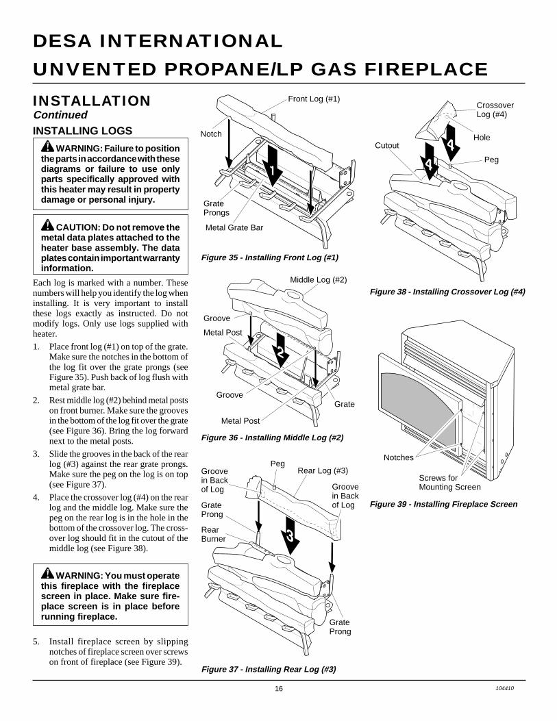
Figure 35 - Installing Front Log (#1)
GrateProngs
Metal Grate Bar
Front Log (#1)
Notch
Rear Log (#3)Peg
GrateProng
GrateProng
RearBurner
Groovein Backof Log
Groovein Backof Log
Figure 37 - Installing Rear Log (#3)
INSTALLATIONContinued
Middle Log (#2)
Metal Post
Metal Post
Groove
GrooveGrate
Figure 36 - Installing Middle Log (#2)
Figure 38 - Installing Crossover Log (#4)
CrossoverLog (#4)
Hole
Peg
Cutout
Notches
Figure 39 - Installing Fireplace Screen
WARNING: You must operatethis fireplace with the fireplacescreen in place. Make sure fire-place screen is in place beforerunning fireplace.
Screws forMounting Screen
WARNING: Failure to positionthe parts in accordance with thesediagrams or failure to use onlyparts specifically approved withthis heater may result in propertydamage or personal injury.
INSTALLING LOGS
Each log is marked with a number. Thesenumbers will help you identify the log wheninstalling. It is very important to installthese logs exactly as instructed. Do notmodify logs. Only use logs supplied withheater.
1. Place front log (#1) on top of the grate.Make sure the notches in the bottom ofthe log fit over the grate prongs (seeFigure 35). Push back of log flush withmetal grate bar.
2. Rest middle log (#2) behind metal postson front burner. Make sure the groovesin the bottom of the log fit over the grate(see Figure 36). Bring the log forwardnext to the metal posts.
3. Slide the grooves in the back of the rearlog (#3) against the rear grate prongs.Make sure the peg on the log is on top(see Figure 37).
4. Place the crossover log (#4) on the rearlog and the middle log. Make sure thepeg on the rear log is in the hole in thebottom of the crossover log. The cross-over log should fit in the cutout of themiddle log (see Figure 38).
5. Install fireplace screen by slippingnotches of fireplace screen over screwson front of fireplace (see Figure 39).
CAUTION: Do not remove themetal data plates attached to theheater base assembly. The dataplates contain important warrantyinformation.

17104410
OWNER’S MANUAL
Figure 41 - Pilot
CAUTION: Do not try to adjustheating levels by using themanual shutoff valve.
Thermo-couple
LIGHTINGINSTRUCTIONS
WARNING: You must operatethis fireplace with the fireplacescreen in place. Make sure fire-place screen is installed beforerunning fireplace.
NOTICE: During initial operationof new fireplace, burning logswill give off a paper-burningsmell. Orange flame will also bepresent. Open window to ventsmell. Operate fireplace on HIposition to burn off odor. Thiswill only last a few hours.
1. STOP! Read the safety information,column 1.
2. Make sure manual shutoff valve isfully open.
3. Turn control knob clockwise Clockwise
to the OFF position (see Figure 40).4. Wait five (5) minutes to clear out any
gas. Then smell for gas, includingnear the floor. If you smell gas,STOP! Follow “B” in the safety in-formation, column 1. If you don’tsmell gas, go to the next step.
5. Turn control knob counterclockwiseC-clockwise to the PILOT position.
Press in control knob for five (5) sec-onds (see Figure 40).Note: If running fireplace for firsttime, there will be air in gas line. Youmay need to press in control knob for30 seconds or longer. This will allowair to bleed from the gas system.
6. Continue pressing control knob in.Press and release ignitor button. Thiswill light pilot. The pilot is attachedto the front burner. If needed, keeppressing ignitor button until pilotlights.Note: If pilot does not stay lit, con-tact a qualified service person or gassupplier for repairs. Until repairs aremade, light pilot with match. To lightpilot with match, see Manual Light-ing Procedure, page 18.
A. This appliance has a pilot which mustbe lighted by hand. When lighting thepilot, follow these instructions exactly.
B. BEFORE LIGHTING smell allaround the appliance area for gas. Besure to smell next to the floor becausesome gas is heavier than air and willsettle on the floor.WHAT TO DO IF YOU SMELLGAS• Do not try to light any appliance.• Do not touch any electric switch; do
not use any phone in your building.• Immediately call your gas supplier
from a neighbor’s phone. Followthe gas supplier’s instructions.
• If you cannot reach your gas sup-plier, call the fire department.
C. Use only your hand to push in or turnthe gas control knob. Never use tools.If the knob will not push in or turnby hand, don’t try to repair it, call aqualified service technician or gassupplier. Force or attempted repairmay result in a fire or explosion.
D. Do not use this appliance if any parthas been under water. Immediatelycall a qualified service technician toinspect the appliance and to replaceany part of the control system andany gas control which has been un-der water.
WARNING: If you do not fol-low these instructions exactly, afire or explosion may result caus-ing property damage, personalinjury or loss of life.
FOR YOUR SAFETYREAD BEFORE
LIGHTING
OPERATINGFIREPLACEThermostat-Controlled Models
Continued
Figure 40 - Control Knob and IgnitorButton Location
Ignitor ElectrodePilot Burner
Ignitor Button
Control Knob
7. Keep control knob pressed in for 30seconds after lighting pilot. After 30seconds, release control knob.Note: If pilot goes out, repeat steps3 through 7. This fireplace has asafety interlock system. Wait one (1)minute for system to reset beforelighting pilot again.• If control knob does not pop out
when released, contact a qualifiedservice person or gas supplier forrepairs.
8. Turn control knob counterclockwiseC-clockwise to desired heating level. The
burners should light. Set controlknob to any heat level between HIand LO.

18 104410
UNVENTED PROPANE/LP GAS FIREPLACE
DESA INTERNATIONAL
OPERATINGFIREPLACEContinued
TO TURN OFF GASTO APPLIANCE
You can set the thermostat control knobto any comfort level between HI and LO.The thermostat will gradually modulatethe heat output and flame height fromhigher to lower settings, or pilot, in orderto maintain the comfort level you select.The ideal comfort setting will vary byhousehold depending upon the amount ofspace to be heated, the output of thecentral heating system, etc.
Note: Selecting the HI setting will causethe burner to remain on without modu-lating down in most cases.
Shutting Off Fireplace
Turn control knob clockwise Clockwise tothe OFF position.
Shutting Off Burners Only (pilotstays lit)
Turn control knob clockwise Clockwise tothe PILOT position.
THERMOSTATCONTROL
OPERATION
MANUAL LIGHTINGPROCEDURE
1. Follow steps 1 through 5 under Light-ing Instructions, page 17.
2. Depress control knob and light pilotwith match.
3. Keep control knob pressed in for 30seconds after lighting pilot. After 30seconds, release control knob. Nowfollow step 8, page 17.
Manually-Controlled Models
A. This appliance has a pilot which mustbe lighted by hand. When lighting thepilot, follow these instructions exactly.
B. BEFORE LIGHTING smell allaround the appliance area for gas. Besure to smell next to the floor becausesome gas is heavier than air and willsettle on the floor.WHAT TO DO IF YOU SMELLGAS• Do not try to light any appliance.• Do not touch any electric switch; do
not use any phone in your building.• Immediately call your gas supplier
from a neighbor’s phone. Followthe gas supplier’s instructions.
• If you cannot reach your gas sup-plier, call the fire department.
C. Use only your hand to push in or turnthe gas control knob. Never use tools.If the knob will not push in or turnby hand, don’t try to repair it, call aqualified service technician or gassupplier. Force or attempted repairmay result in a fire or explosion.
D. Do not use this appliance if any parthas been under water. Immediatelycall a qualified service technician toinspect the appliance and to replaceany part of the control system andany gas control which has been un-der water.
WARNING: If you do not fol-low these instructions exactly, afire or explosion may result caus-ing property damage, personalinjury or loss of life.
FOR YOUR SAFETYREAD BEFORE
LIGHTING
IGNITOR
Figure 42 - Control Knob and IgnitorButton Location
LIGHTINGINSTRUCTIONS
WARNING: You must operatethis fireplace with the fireplacescreen in place. Make sure fire-place screen is installed beforerunning fireplace.
NOTICE: During initial operationof new fireplace, burning logswill give off a paper-burningsmell. Orange flame will also bepresent. Open window to ventsmell. Operate fireplace on HIposition to burn off odor. Thiswill only last a few hours.
1. STOP! Read the safety information,column 2.
2. Make sure manual shutoff valve isfully open.
3. Turn control knob clockwise Clockwise
to the OFF position (see Figure 42).4. Wait five (5) minutes to clear out any
gas. Then smell for gas, includingnear the floor. If you smell gas,STOP! Follow “B” in the safety in-formation, column 2. If you don’tsmell gas, go to the next step.
5. Slightly depress and turn control knobcounterclockwise C-clockwise to the PI-LOT position. Press in control knobfor five (5) seconds (see Figure 42).Note: If running fireplace for firsttime, there will be air in gas line. Youmay need to press in control knob for30 seconds or longer. This will allowair to bleed from the gas system.
Ignitor Button
Control Knob

19104410
OWNER’S MANUAL
Figure 43 - Pilot
6. Continue pressing control knob in.Press and release ignitor button. Thiswill light pilot. The pilot is attached tothe front burner. If needed, keep press-ing ignitor button until pilot lights.Note : If pilot does not stay lit, con-tact a qualified service person or gassupplier for repairs. Until repairs aremade, light pilot with match. To lightpilot with match, see Manual Light-ing Procedure, column 3.
7. Keep control knob pressed in for 30seconds after lighting pilot. After 30seconds, release control knob.Note: If pilot goes out, repeat steps3 through 7.• If control knob does not pop out
when released, contact a qualifiedservice person or gas supplier forrepairs.
8. Slightly depress and turn controlknob couterclockwise to thehigh position. Both burners shouldlight. Set control knob to eitherHIGH or LOW.
OPERATINGFIREPLACEContinued
TO TURN OFF GASTO APPLIANCE
WARNING: Do not operateheater between locked positions.
CAUTION: Do not try to adjustheating levels by using themanual shutoff valve.
The variable control valve can be set to anyheat setting and flame height desired, bysimply turning the control knob until thatsetting is attained. Even the lowest settingprovides realistic flames and glowing em-bers from two burners. Selecting highersettings produces greater heat output. Thisresults in increased heating comfort.
Shutting Off Fireplace1. Turn control knob clockwise Clockwise
to the HIGH position.2. Slightly depress control knob and
turn clockwise Clockwise to the PILOTposition.
3. Slightly depress control knob andturn clockwise Clockwise to the OFFposition.
Shutting Off Burners Only (pilotstays lit)1. Turn control knob clockwise Clockwise
to the HIGH position.2. Press in and turn clockwise Clockwise
to the PILOT position.
ThermocoupleIgnitor Electrode
Pilot Burner
VARIABLE CONTROLOPERATION
MANUAL LIGHTINGPROCEDURE
1. Follow steps 1 through 5 under Light-ing Instructions, page 18.
2. Depress control knob and light pilotwith match.
3. Keep control knob pressed in for 30seconds after lighting pilot. After 30seconds, release control knob. Nowfollow step 8, column 1.
20 104410
UNVENTED PROPANE/LP GAS FIREPLACE
DESA INTERNATIONAL
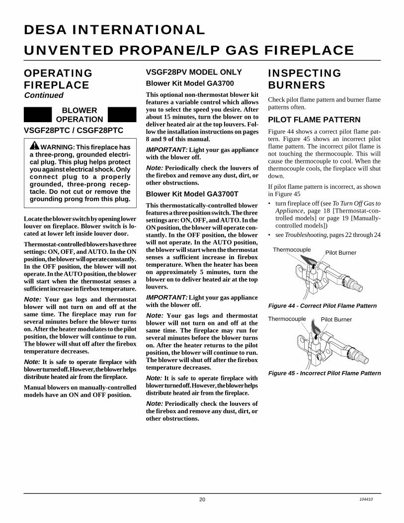
INSPECTINGBURNERSCheck pilot flame pattern and burner flamepatterns often.
PILOT FLAME PATTERNFigure 44 shows a correct pilot flame pat-tern. Figure 45 shows an incorrect pilotflame pattern. The incorrect pilot flame isnot touching the thermocouple. This willcause the thermocouple to cool. When thethermocouple cools, the fireplace will shutdown.
If pilot flame pattern is incorrect, as shownin Figure 45
• turn fireplace off (see To Turn Off Gas toAppliance, page 18 [Thermostat-con-trolled models] or page 19 [Manually-controlled models])
• see Troubleshooting, pages 22 through 24
Figure 44 - Correct Pilot Flame Pattern
Figure 45 - Incorrect Pilot Flame Pattern
Thermocouple Pilot Burner
Pilot BurnerThermocouple
OPERATINGFIREPLACEContinued
Blower Kit Model GA3700T
This thermostatically-controlled blowerfeatures a three position switch. The threesettings are: ON, OFF, and AUTO. In theON position, the blower will operate con-stantly. In the OFF position, the blowerwill not operate. In the AUTO position,the blower will start when the thermostatsenses a sufficient increase in fireboxtemperature. When the heater has beenon approximately 5 minutes, turn theblower on to deliver heated air at the toplouvers.
IMPORTANT: Light your gas appliancewith the blower off.
Note: Your gas logs and thermostatblower will not turn on and off at thesame time. The fireplace may run forseveral minutes before the blower turnson. After the heater returns to the pilotposition, the blower will continue to run.The blower will shut off after the fireboxtemperature decreases.
Note: It is safe to operate fireplace withblower turned off. However, the blower helpsdistribute heated air from the fireplace.
Note: Periodically check the louvers ofthe firebox and remove any dust, dirt, orother obstructions.
Locate the blower switch by opening lowerlouver on fireplace. Blower switch is lo-cated at lower left inside louver door.
Thermostat-controlled blowers have threesettings: ON, OFF, and AUTO. In the ONposition, the blower will operate constantly.In the OFF position, the blower will notoperate. In the AUTO position, the blowerwill start when the thermostat senses asufficient increase in firebox temperature.
Note: Your gas logs and thermostatblower will not turn on and off at thesame time. The fireplace may run forseveral minutes before the blower turnson. After the heater modulates to the pilotposition, the blower will continue to run.The blower will shut off after the fireboxtemperature decreases.
Note: It is safe to operate fireplace withblower turned off. However, the blower helpsdistribute heated air from the fireplace.
Manual blowers on manually-controlledmodels have an ON and OFF position.
BLOWEROPERATION
WARNING: This fireplace hasa three-prong, grounded electri-cal plug. This plug helps protectyou against electrical shock. Onlyconnect plug to a properlygrounded, three-prong recep-tacle. Do not cut or remove thegrounding prong from this plug.
VSGF28PTC / CSGF28PTC
VSGF28PV MODEL ONLYBlower Kit Model GA3700
This optional non-thermostat blower kitfeatures a variable control which allowsyou to select the speed you desire. Afterabout 15 minutes, turn the blower on todeliver heated air at the top louvers. Fol-low the installation instructions on pages8 and 9 of this manual.
IMPORTANT: Light your gas appliancewith the blower off.
Note: Periodically check the louvers ofthe firebox and remove any dust, dirt, orother obstructions.
21104410
OWNER’S MANUAL
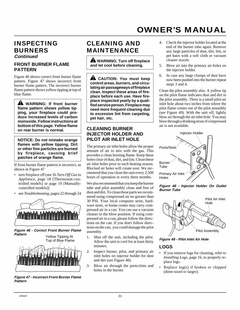
FRONT BURNER FLAMEPATTERNFigure 46 shows correct front burner flamepattern. Figure 47 shows incorrect frontburner flame pattern. The incorrect burnerflame pattern shows yellow tipping at top ofblue flame.
WARNING: If front burnerflame pattern shows yellow tip-ping, your fireplace could pro-duce increased levels of carbonmonoxide. Follow instructions atbottom of this page. Yellow flameon rear burner is normal.
NOTICE: Do not mistake orangeflames with yellow tipping. Dirtor other fine particles are burnedby fireplace, causing briefpatches of orange flame.
CLEANING ANDMAINTENANCE
WARNING: Turn off fireplaceand let cool before cleaning.
CAUTION: You must keepcontrol areas, burners, and circu-lating air passageways of fireplaceclean. Inspect these areas of fire-place before each use. Have fire-place inspected yearly by a quali-fied service person. Fireplace mayneed more frequent cleaning dueto excessive lint from carpeting,pet hair, etc.
LOGS• If you remove logs for cleaning, refer to
Installing Logs, page 16, to properly re-place logs.
• Replace log(s) if broken or chipped(dime-sized or larger).
If front burner flame pattern is incorrect, asshown in Figure 47
• turn fireplace off (see To Turn Off Gas toAppliance, page 18 [Thermostat-con-trolled models] or page 19 [Manually-controlled models])
• see Troubleshooting, pages 22 through 24
Figure 47 - Incorrect Front Burner FlamePattern
Figure 46 - Correct Front Burner FlamePattern
Yellow Tipping AtTop of Blue Flame
INSPECTINGBURNERSContinued
CLEANING BURNERINJECTOR HOLDER ANDPILOT AIR INLET HOLEThe primary air inlet holes allow the properamount of air to mix with the gas. Thisprovides a clean burning flame. Keep theseholes clear of dust, dirt, and lint. Clean theseair inlet holes prior to each heating season.Blocked air holes will create soot. We rec-ommend that you clean the unit every 2,500hours of operation or every three months.
We also recommend that you keep the burnertube and pilot assembly clean and free ofdust and dirt. To clean these parts we recom-mend using compressed air no greater than30 PSI. Your local computer store, hard-ware store, or home center may carry com-pressed air in a can. You can use a vacuumcleaner in the blow position. If using com-pressed air in a can, please follow the direc-tions on the can. If you don't follow direc-tions on the can, you could damage the pilotassembly.
1. Shut off the unit, including the pilot.Allow the unit to cool for at least thirtyminutes.
2. Inspect burner, pilot, and primary airinlet holes on injector holder for dustand dirt (see Figure 48).
3. Blow air through the ports/slots andholes in the burner.
Figure 48 - Injector Holder On OutletBurner Tube
4. Check the injector holder located at theend of the burner tube again. Removeany large particles of dust, dirt, lint, orpet hairs with a soft cloth or vacuumcleaner nozzle.
5. Blow air into the primary air holes onthe injector holder.
6. In case any large clumps of dust havenow been pushed into the burner repeatsteps 3 and 4.
Clean the pilot assembly also. A yellow tipon the pilot flame indicates dust and dirt inthe pilot assembly. There is a small pilot airinlet hole about two inches from where thepilot flame comes out of the pilot assembly(see Figure 49). With the unit off, lightlyblow air through the air inlet hole. You mayblow through a drinking straw if compressedair is not available.
BurnerTube
Injector Holder
Primary Air InletHoles
Figure 49 - Pilot Inlet Air Hole
Pilot Assembly
Pilot Air InletHole
Ports/Slots
22 104410
UNVENTED PROPANE/LP GAS FIREPLACE
DESA INTERNATIONAL
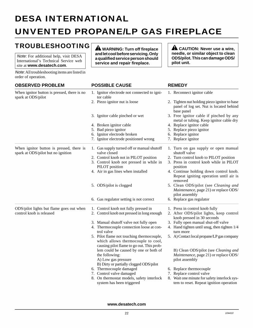
POSSIBLE CAUSE
1. Ignitor electrode not connected to igni-tor cable
2. Piezo ignitor nut is loose
3. Ignitor cable pinched or wet
4. Broken ignitor cable5. Bad piezo ignitor6. Ignitor electrode broken7. Ignitor electrode positioned wrong
1. Gas supply turned off or manual shutoffvalve closed
2. Control knob not in PILOT position3. Control knob not pressed in while in
PILOT position4. Air in gas lines when installed
5. ODS/pilot is clogged
6. Gas regulator setting is not correct
1. Control knob not fully pressed in2. Control knob not pressed in long enough
3. Manual shutoff valve not fully open4. Thermocouple connection loose at con-
trol valve5. Pilot flame not touching thermocouple,
which allows thermocouple to cool,causing pilot flame to go out. This prob-lem could be caused by one or both ofthe following:A) Low gas pressureB) Dirty or partially clogged ODS/pilot
6. Thermocouple damaged7. Control valve damaged8. On thermostat models, safety interlock
system has been triggered
REMEDY
1. Reconnect ignitor cable
2. Tighten nut holding piezo ignitor to basepanel of log set. Nut is located behindbase panel
3. Free ignitor cable if pinched by anymetal or tubing. Keep ignitor cable dry
4. Replace ignitor cable5. Replace piezo ignitor6. Replace ignitor7. Replace ignitor
1. Turn on gas supply or open manualshutoff valve
2. Turn control knob to PILOT position3. Press in control knob while in PILOT
position4. Continue holding down control knob.
Repeat igniting operation until air isremoved
5. Clean ODS/pilot (see Cleaning andMaintenance, page 21) or replace ODS/pilot assembly
6. Replace gas regulator
1. Press in control knob fully2. After ODS/pilot lights, keep control
knob pressed in 30 seconds3. Fully open manual shut-off valve4. Hand tighten until snug, then tighten 1/4
turn more5. A) Contact local propane/LP gas company
B) Clean ODS/pilot (see Cleaning andMaintenance, page 21) or replace ODS/pilot assembly
6. Replace thermocouple7. Replace control valve8. Wait one minute for safety interlock sys-
tem to reset. Repeat ignition operation
OBSERVED PROBLEM
When ignitor button is pressed, there is nospark at ODS/pilot
When ignitor button is pressed, there isspark at ODS/pilot but no ignition
ODS/pilot lights but flame goes out whencontrol knob is released
TROUBLESHOOTING WARNING: Turn off fireplaceand let cool before servicing. Onlya qualified service person shouldservice and repair fireplace.
CAUTION: Never use a wire,needle, or similar object to cleanODS/pilot. This can damage ODS/pilot unit.
Note: For additional help, visit DESAInternational’s Technical Service website at www.desatech.com .
Note: All troubleshooting items are listed inorder of operation.
www.desatech.com

23104410
OWNER’S MANUAL
TROUBLESHOOTINGContinued
OBSERVED PROBLEM
One or both burners do not light after ODS/pilot is lit
Delayed ignition of one or both burners
Burner backfiring during combustion
Yellow flame in front burner during burnercombustion
Slight smoke or odor during initial operation
Fireplace produces a whistling noise whenburners are lit
White powder residue forming within burnerbox or on adjacent walls or furniture
Dark residue on logs or inside of fireplace
REMEDY
1. Clean burner(s) (see Cleaning and Main-tenance, page 21) or replace burnerorifice(s)
2. Replace burner orifice(s)3. Contact local propane/LP gas company4. Contact qualified service person
1. Contact local propane/LP gas company2. Clean burner(s) (see Cleaning and Main-
tenance, page 21) or replace burnerorifice(s)
3. Contact qualified service person
1. Clean burner (see Cleaning and Mainte-nance, page 21) or replace burner orifice
2. Replace damaged burner3. Replace gas regulator
1. Check burner(s) for dirt and debris. Iffound, clean burner(s) (see Cleaning andMaintenance, page 21)
2. Replace gas regulator
1. Problem will stop after a few hours ofoperation
1. Turn control knob to LO position andlet warm up for a minute
2. Operate burners until air is removedfrom line. Have gas line checked by lo-cal propane/LP gas company
3. Observe minimum installation clear-ances (see pages 12 and 13)
4. Clean burners (see Cleaning and Main-tenance, page 21) or replace burnerorifice(s)
1. Turn heater off when using furniturepolish, wax, carpet cleaners, or similarproducts
1. Properly locate logs (see Installing Logs,page 16)
2. Eliminate source of drafts around heater
3. Clean out air holes at burner inlet. Peri-odically repeat as needed
4. Remove blockage or replace burner
POSSIBLE CAUSE
1. Burner orifice(s) clogged
2. Burner orifice(s) diameter is too small3. Inlet gas pressure is too low4. Mislocated crossover tube
1. Manifold pressure is too low2. Burner orifice(s) clogged
3. Mislocated crossover tube
1. Burner orifice is clogged or damaged
2. Damaged burner3. Gas regulator defective
1. Not enough air
2. Gas regulator defective
1. Residues from manufacturing processesand logs curing
1. Turning control knob to HI positionwhen burners are cold
2. Air in gas line
3. Air passageways on fireplace blocked
4. Dirty or partially clogged burnerorifice(s)
1. When heated, vapors from furniture pol-ish, wax, carpet cleaners, etc. turn intowhite powder residue
1. Improper log placement
2. Drafts or other air currents affectingflame pattern
3. Air holes at burner inlet blocked
4. Burner flame holes blocked
Continuedwww.desatech.com

24 104410
UNVENTED PROPANE/LP GAS FIREPLACE
DESA INTERNATIONAL
TROUBLESHOOTINGContinued
WARNING: If you smell gas• Shut off gas supply.• Do not try to light any appliance.• Do not touch any electrical switch; do not use any phone in your
building.• Immediately call your gas supplier from a neighbor’s phone. Follow the
gas supplier’s instructions.• If you cannot reach your gas supplier, call the fire department.
IMPORTANT: Operating fireplace where impurities in air exist may create odors. Cleaningsupplies, paint, paint remover, cigarette smoke, cements and glues, new carpet or textiles,etc., create fumes. These fumes may mix with combustion air and create odors. These odorswill disappear over time.
POSSIBLE CAUSE
1. Metal expanding while heating or con-tracting while cooling
1. Fireplace burning vapors from paint, hairspray, glues, cleaners, chemicals, newcarpet, etc. (See IMPORTANT state-ment above)
2. Gas leak. See Warning statementabove
1. Not enough fresh air is available2. Low line pressure3. ODS/pilot is partially clogged
1. Gas leak. See Warning statementabove
2. Control valve defective
1. Foreign matter between control valveand burner
2. Gas leak. See Warning statementabove
1. Not enough combustion/ventilation air
OBSERVED PROBLEM
Fireplace produces a clicking/ticking noisejust after burners are lit or shut off
Fireplace produces unwanted odors
Fireplace shuts off in use (ODS operates)
Gas odor even when control knob is in OFFposition
Gas odor during combustion
Moisture/condensation noticed on windows
REMEDY
1. This is common with most fireplaces. Ifnoise is excessive, contact qualified ser-vice person
1. Open window and ventilate room. Stopusing odor causing products while fire-place is running
2. Locate and correct all leaks (see Check-ing Gas Connections, page 15)
1. Open window and/or door for ventilation2. Contact local propane/LP gas company3. Clean ODS/pilot (see Cleaning and
Maintenance, page 21)
1. Locate and correct all leaks (see Check-ing Gas Connections, page 15)
2. Replace control valve
1. Take apart gas tubing and removeforeign matter
2. Locate and correct all leaks (see Check-ing Gas Connections, page 15)
1. Refer to Air for Combustion and Venti-lation requirements (page 4)
www.desatech.com
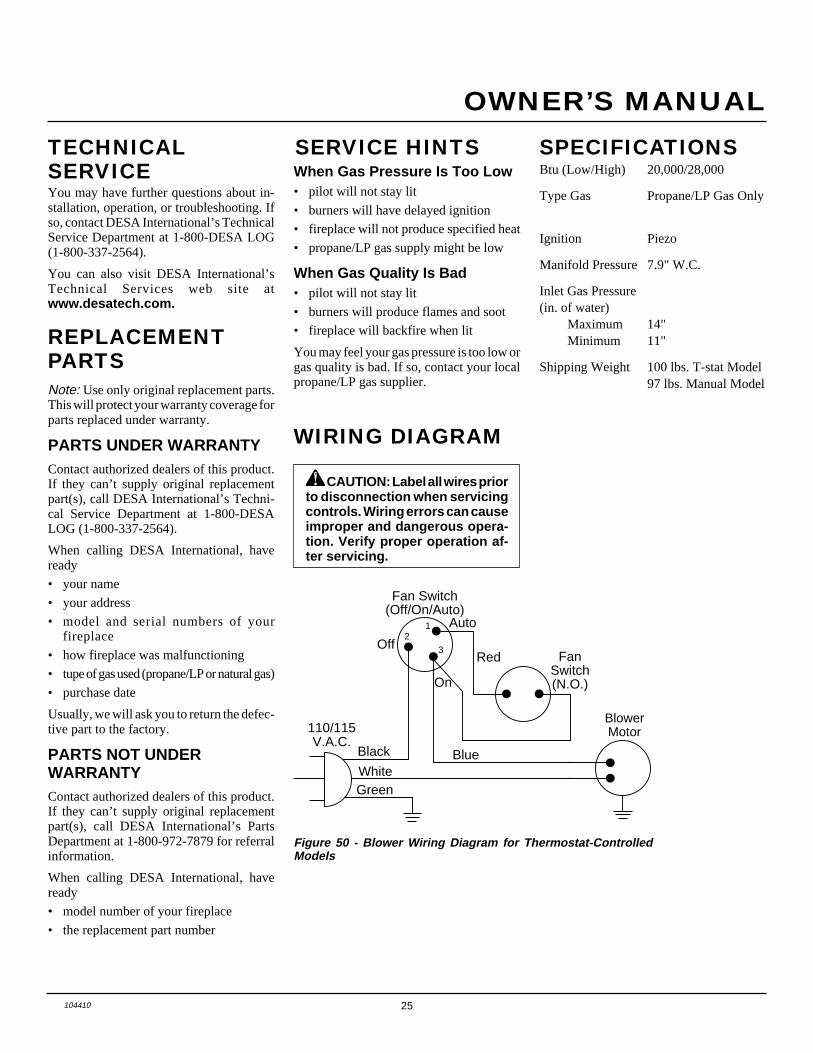
25104410
OWNER’S MANUAL
SERVICE HINTSWhen Gas Pressure Is Too Low• pilot will not stay lit
• burners will have delayed ignition
• fireplace will not produce specified heat
• propane/LP gas supply might be low
When Gas Quality Is Bad• pilot will not stay lit
• burners will produce flames and soot
• fireplace will backfire when lit
You may feel your gas pressure is too low orgas quality is bad. If so, contact your localpropane/LP gas supplier.
TECHNICALSERVICEYou may have further questions about in-stallation, operation, or troubleshooting. Ifso, contact DESA International’s TechnicalService Department at 1-800-DESA LOG(1-800-337-2564).
You can also visit DESA International’sTechnical Services web site atwww.desatech.com.
REPLACEMENTPARTSNote: Use only original replacement parts.This will protect your warranty coverage forparts replaced under warranty.
PARTS UNDER WARRANTYContact authorized dealers of this product.If they can’t supply original replacementpart(s), call DESA International’s Techni-cal Service Department at 1-800-DESALOG (1-800-337-2564).
When calling DESA International, haveready
• your name
• your address
• model and serial numbers of yourfireplace
• how fireplace was malfunctioning
• tupe of gas used (propane/LP or natural gas)
• purchase date
Usually, we will ask you to return the defec-tive part to the factory.
PARTS NOT UNDERWARRANTYContact authorized dealers of this product.If they can’t supply original replacementpart(s), call DESA International’s PartsDepartment at 1-800-972-7879 for referralinformation.
When calling DESA International, haveready
• model number of your fireplace
• the replacement part number
Btu (Low/High) 20,000/28,000
Type Gas Propane/LP Gas Only
Ignition Piezo
Manifold Pressure 7.9" W.C.
Inlet Gas Pressure(in. of water)
Maximum 14"Minimum 11"
Shipping Weight 100 lbs. T-stat Model97 lbs. Manual Model
Figure 50 - Blower Wiring Diagram for Thermostat-ControlledModels
SPECIFICATIONS
WIRING DIAGRAM
CAUTION: Label all wires priorto disconnection when servicingcontrols. Wiring errors can causeimproper and dangerous opera-tion. Verify proper operation af-ter servicing.
Blue
Fan Switch(Off/On/Auto)
Red FanSwitch(N.O.)
GreenWhite
On
110/115 V.A.C.
BlowerMotor
Black
Off
12
3
Auto

26 104410
UNVENTED PROPANE/LP GAS FIREPLACE
DESA INTERNATIONAL
MANUAL SHUTOFF VALVEGA5010For all models. Manual shutoff valve with1/8" NPT tap. Fits 1/2" NPT pipe.
SLIM HEARTH BASE(Not Shown)G3005J Series - Jade MarbleLaminateG3005S Series - SandstoneMarble LaminateG3005B Series - Black OnyxMarble Laminate
The slim hearth base allows you to furthercustomize your fireplace.
Dimensions (WxHxD): 41 7/8" x 5/8" x 10"
BLOWER ACCESSORIESGA3700 SeriesManual variable control for VSGF28PVAseries only.
GA3700T SeriesThermostatic control for VSGF28PV seriesonly.
ACCESSORIESPurchase these fireplace accessories fromyour local dealer. If they can not supplythese accessories, call DESA International’sSales Department at 1-800-432-2382 forinformation. You can also write to the ad-dress listed on the back page of this manual.
������������������������������������������������������
QQQQQQQQQQQQQQQQQQQQQQQQQQQQQQQQQQQQQQQQQQQQQQQQQQQQQQ
¢¢¢¢¢¢¢¢¢¢¢¢¢¢¢¢¢¢¢¢¢¢¢¢¢¢¢¢¢¢¢¢¢¢¢¢¢¢¢¢¢¢¢¢¢¢¢¢¢¢¢¢¢¢
���������
QQQQQQQQQ
¢¢¢¢¢¢¢¢¢
������������������������������
QQQQQQQQQQQQQQQQQQQQQQQQQQQQQQ
¢¢¢¢¢¢¢¢¢¢¢¢¢¢¢¢¢¢¢¢¢¢¢¢¢¢¢¢¢¢
CABINET MANTELGM100F Series - Walnut FinishedGM101U Series - UnfinishedGM106F Series - Oak Finishedwith Medium StainGM107U Series - UnfinishedGM102W Series - Off-White Paint
Shown with optional base and laminate hearthand mantel trim accessories.
Dimensions (WxHxD): 56 3/4" x 48" x 22 3/4"
HARDWOOD HEARTH BASEG3000F Series- Walnut FinishedG3001U Series - UnfinishedG3006F Series - Oak Finishedwith Medium StainG3007U Series - Unfinished OakG3004W Series - Off-White Paint
The hearth base creates a handsome riser forthe fireplace (cannot be used with cornermantel).
Dimensions (WxHxD): 58" x 6 1/2" x 28 9/16"

27104410
OWNER’S MANUAL
������������������������������������������������������
QQQQQQQQQQQQQQQQQQQQQQQQQQQQQQQQQQQQQQQQQQQQQQQQQQQQQQ
¢¢¢¢¢¢¢¢¢¢¢¢¢¢¢¢¢¢¢¢¢¢¢¢¢¢¢¢¢¢¢¢¢¢¢¢¢¢¢¢¢¢¢¢¢¢¢¢¢¢¢¢¢¢
CORNER MANTELGM200F Series - WalnutFinishedGM201U Series - Unfinished
Shown with optional laminate mantel trimaccessory.
Dimensions (WxHxD): 60 7/8" x 48 3/4" x 34 5/8"
ACCESSORIESContinued
��������������������
QQQQQQQQQQQQQQQQQQQQ
¢¢¢¢¢¢¢¢¢¢¢¢¢¢¢¢¢¢¢¢
��QQ¢¢����QQQQ¢¢¢¢
����������QQQQQQQQQQ¢¢¢¢¢¢¢¢¢¢
LAMINATE TRIM FORHEARTH OR MANTEL
G3002J Series - Jade MarbleLaminate Mantel TrimG3003J Series - Jade MarbleLaminate Hearth Base TrimG3002S Series - SandstoneMarble Laminate Mantel TrimG3003S Series - SandstoneMarble Laminate Hearth BaseTrimG3002B Series - Black OnyxMarble Laminate TrimG3003B Series - Black OnyxMarble Laminate Hearth BaseTrim
Mantel trim for cabinet or corner mantel.Hearth base trim for hardwood hearth bases.
Hearth Base Trim
Mantel Trim
FIREBOX BRICK LINERG8000 Series (Not Shown)Ceramic fiber firebox liner adds the look ofreal brick.
BRASS TRIM ACCESSORYGA6090 (Not Shown)Included with accessory mantels
DUPLEX OUTLET KITGA3555 (Not Shown)For built-in installation

28 104410
UNVENTED PROPANE/LP GAS FIREPLACE
DESA INTERNATIONAL
ILLUSTRATEDPARTSBREAKDOWNLOG BASE ASSEMBLY
VARIABLE MANUALLY-CONTROLLED MODELS
VSGF28PVA
26
7
8
7
7
1812
11
7
5
6 6-1 6-2
9
17
22
15
10
25
13
5
5
5
520
14
1831
28
23
29
19
2730
24
16
21
1
2
3
4

29104410
OWNER’S MANUAL
PARTS LISTLOG BASE ASSEMBLY
VARIABLE MANUALLY-CONTROLLED MODELS
VSGF28PVA
This list contains replaceable parts used in your fireplace. When ordering parts, follow theinstructions listed under Replacement Parts on page 25 of this manual.
KEYNO. PART NUMBER DESCRIPTION QTY.
1 104388-02 Front Log (#1) 12 104390-02 Middle Log (#2) 13 104392-02 Rear Log (#3) 14 104394-02 Crossover Log (#4) 15 098304-01 Screw, #10 Phillips, Black 86 099059-02 O.D.S. Pilot 1 6-1 098594-01 Ignitor 1 6-2 098593-01 Thermocouple 17 098249-01 Nut 68 101006-01 Pilot Bracket 19 101330-05 Front Burner Assembly 110 100999-02 Rear Burner Assembly 111 102257-08CJ Base Assembly 112 098271-06 Ignitor Cable 113 103410-01CK Firebox Bottom 114 098867-10 Gas Regulator 115 101004-01 Front Burner Injector 116 102445-01 Piezo Ignitor 117 101007-01 Crossover Tube 118 099387-05 Pilot Tube 119 101972-01 Valve and Piezo Bracket 120 M11084-38 Regulator Hex Screw 221 102668-01 Front Burner Tube 122 101008-01 Gasket 123 101973-01 Inlet Tube 124 098276-01 1/8" Plug 125 101004-15 Rear Burner Injector 126 M11084-26 Hex Screw, #10 227 098508-01 Valve Retainer Nut 128 101628-03 Flex Hose 129 097809-02 Adapter 130 098354-01 Control Knob 131 102568-02 Control Valve 1
PARTS AVAILABLE — NOT SHOWN
100563-01 Warning Plate 1101055-02 Lighting Instructions Plate 1100565-01 Warning Plate Fastener 1104354-01 Information Video 1101976-02 Control Position Decal 1

30 104410
UNVENTED PROPANE/LP GAS FIREPLACE
DESA INTERNATIONAL
ILLUSTRATEDPARTSBREAKDOWNLOG BASE ASSEMBLY
THERMOSTAT-CONTROLLED MODELS
VSGF28PTCCSGF28PTC
17
5
26
7
8
7
7
18
12
11
1
2
4
3
6 6-1 6-2
9
15
10
25
13
28
5
5
5
5
21
24
22
18
23
12 6-2
19
1427
20
16
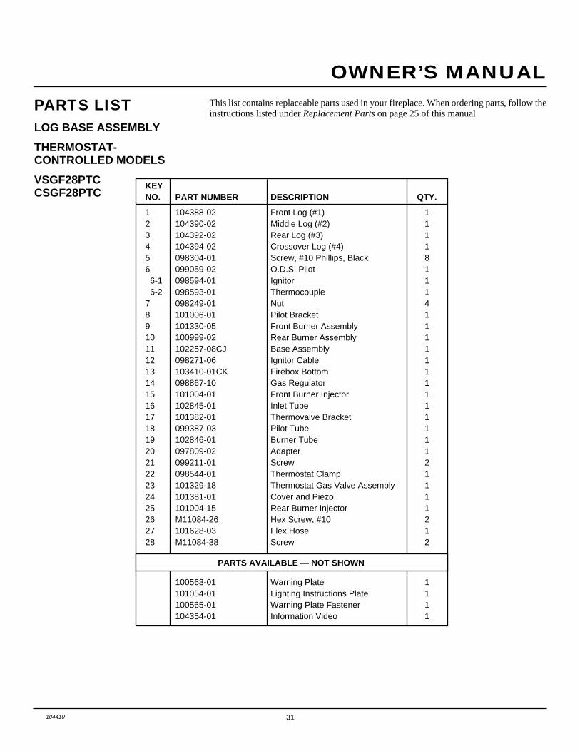
31104410
OWNER’S MANUAL
PARTS LISTLOG BASE ASSEMBLY
THERMOSTAT-CONTROLLED MODELS
VSGF28PTCCSGF28PTC
This list contains replaceable parts used in your fireplace. When ordering parts, follow theinstructions listed under Replacement Parts on page 25 of this manual.
KEYNO. PART NUMBER DESCRIPTION QTY.
1 104388-02 Front Log (#1) 12 104390-02 Middle Log (#2) 13 104392-02 Rear Log (#3) 14 104394-02 Crossover Log (#4) 15 098304-01 Screw, #10 Phillips, Black 86 099059-02 O.D.S. Pilot 1 6-1 098594-01 Ignitor 1 6-2 098593-01 Thermocouple 17 098249-01 Nut 48 101006-01 Pilot Bracket 19 101330-05 Front Burner Assembly 110 100999-02 Rear Burner Assembly 111 102257-08CJ Base Assembly 112 098271-06 Ignitor Cable 113 103410-01CK Firebox Bottom 114 098867-10 Gas Regulator 115 101004-01 Front Burner Injector 116 102845-01 Inlet Tube 117 101382-01 Thermovalve Bracket 118 099387-03 Pilot Tube 119 102846-01 Burner Tube 120 097809-02 Adapter 121 099211-01 Screw 222 098544-01 Thermostat Clamp 123 101329-18 Thermostat Gas Valve Assembly 124 101381-01 Cover and Piezo 125 101004-15 Rear Burner Injector 126 M11084-26 Hex Screw, #10 227 101628-03 Flex Hose 128 M11084-38 Screw 2
PARTS AVAILABLE — NOT SHOWN
100563-01 Warning Plate 1101054-01 Lighting Instructions Plate 1100565-01 Warning Plate Fastener 1104354-01 Information Video 1
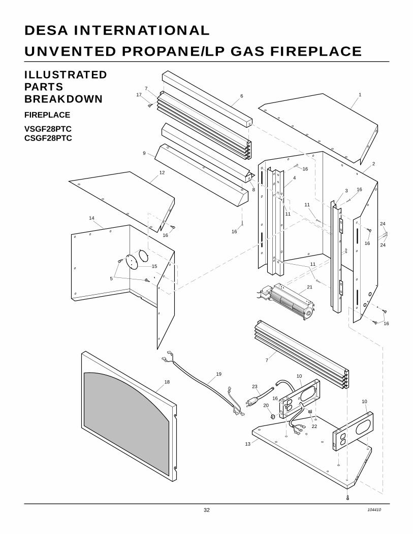
32 104410
UNVENTED PROPANE/LP GAS FIREPLACE
DESA INTERNATIONAL
ILLUSTRATEDPARTSBREAKDOWNFIREPLACE
VSGF28PTCCSGF28PTC
1
2
3
4
16
16
6
12
18
19 10
10
7
13
22
20
23
16
24
24
21
16
16
717
14
5
1616
15
8
9
11
11
11
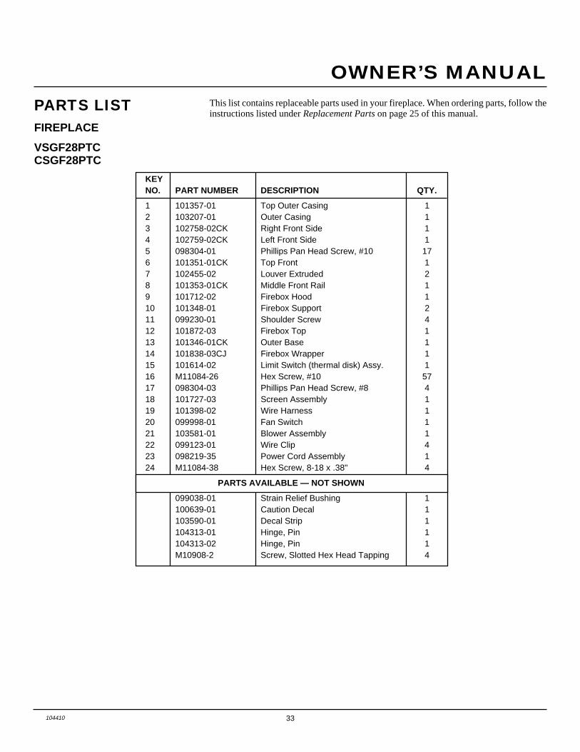
33104410
OWNER’S MANUAL
PARTS LISTFIREPLACE
VSGF28PTCCSGF28PTC
This list contains replaceable parts used in your fireplace. When ordering parts, follow theinstructions listed under Replacement Parts on page 25 of this manual.
KEYNO. PART NUMBER DESCRIPTION QTY.
1 101357-01 Top Outer Casing 12 103207-01 Outer Casing 13 102758-02CK Right Front Side 14 102759-02CK Left Front Side 15 098304-01 Phillips Pan Head Screw, #10 176 101351-01CK Top Front 17 102455-02 Louver Extruded 28 101353-01CK Middle Front Rail 19 101712-02 Firebox Hood 110 101348-01 Firebox Support 211 099230-01 Shoulder Screw 412 101872-03 Firebox Top 113 101346-01CK Outer Base 114 101838-03CJ Firebox Wrapper 115 101614-02 Limit Switch (thermal disk) Assy. 116 M11084-26 Hex Screw, #10 5717 098304-03 Phillips Pan Head Screw, #8 418 101727-03 Screen Assembly 119 101398-02 Wire Harness 120 099998-01 Fan Switch 121 103581-01 Blower Assembly 122 099123-01 Wire Clip 423 098219-35 Power Cord Assembly 124 M11084-38 Hex Screw, 8-18 x .38" 4
PARTS AVAILABLE — NOT SHOWN
099038-01 Strain Relief Bushing 1100639-01 Caution Decal 1103590-01 Decal Strip 1104313-01 Hinge, Pin 1104313-02 Hinge, Pin 1M10908-2 Screw, Slotted Hex Head Tapping 4

34 104410
UNVENTED PROPANE/LP GAS FIREPLACE
DESA INTERNATIONAL
ILLUSTRATEDPARTSBREAKDOWNFIREPLACE
VSGF28PVA
1
2
3 16
4
6
12
1810
10
7
13
16
16
16
717
14
5
1616
15
8
9
16
11
11
11

35104410
OWNER’S MANUAL
PARTS LISTFIREPLACE
VSGF28PVA
This list contains replaceable parts used in your fireplace. When ordering parts, follow theinstructions listed under Replacement Parts on page 25 of this manual.
KEYNO. PART NUMBER DESCRIPTION QTY.
1 101357-01 Top Outer Casing 12 103207-01 Outer Casing 13 102758-02CK Right Front Side 14 102759-02CK Left Front Side 15 098304-01 Phillips Pan Head Screw, #10 176 101351-01CK Top Front 17 102455-02 Louver Extruded 28 101353-01CK Middle Front Rail 19 101712-02 Firebox Hood 110 101348-01 Firebox Support 211 099230-01 Shoulder Screw 412 101872-03 Firebox Top 113 101346-01CK Outer Base 114 101838-03CJ Firebox Wrapper 115 101514-01CK Cover 116 M11084-26 Hex Screw, #10 5717 098304-03 Phillips Pan Head Screw, #8 418 101727-03 Screen Assembly 1
PARTS AVAILABLE — NOT SHOWN
099038-01 Strain Relief Bushing 1100639-01 Caution Decal 1103590-01 Decal Strip 1104313-01 Hinge, Pin 1104313-02 Hinge, Pin 1M10908-2 Screw, Slotted Hex Head Tapping 4

LIMITED WARRANTYVENT-FREE PROPANE/LP GAS FIREPLACE
DESA International warrants this product to be free from defects in materials and components for four (4) years and five (5) years onstainless steel burners from the date of first purchase, provided that the product has been properly installed, operated and maintainedin accordance with all applicable instructions. To make a claim under this warranty the Bill of Sale or cancelled check must be presented.
This warranty is extended only to the original retail purchaser. This warranty covers the cost of part(s) required to restore this heaterto proper operating condition and an allowance for labor when provided by a DESA Authorized Service Center. Warranty part(s) MUSTbe obtained through authorized dealers of this product and/or DESA International who will provide original factory replacement parts.Failure to use original factory replacement parts voids this warranty. The heater MUST be installed by a qualified installer in accordancewith all local codes and instructions furnished with the unit.
This warranty does not apply to parts that are not in original condition because of normal wear and tear, or parts that fail or becomedamaged as a result of misuse, accidents, lack of proper maintenance or defects caused by improper installation. Travel, diagnostic cost,labor, transportation and any and all such other costs related to repairing a defective heater will be the responsibility of the owner.
TO THE FULL EXTENT ALLOWED BY THE LAW OF THE JURISDICTION THAT GOVERNS THE SALE OF THE PRODUCT;THIS EXPRESS WARRANTY EXCLUDES ANY AND ALL OTHER EXPRESSED WARRANTIES AND LIMITS THE DURA-TION OF ANY AND ALL IMPLIED WARRANTIES, INCLUDING WARRANTIES OF MERCHANTABILITY AND FITNESSFOR A PARTICULAR PURPOSE TO FOUR (4) YEARS ON ALL COMPONENTS AND FIVE (5) YEARS ON STAINLESS STEELBURNERS FROM THE DATE OF FIRST PURCHASE; AND DESA INTERNATIONAL’S LIABILITY IS HEREBY LIMITED TOTHE PURCHASE PRICE OF THE PRODUCT AND DESA INTERNATIONAL SHALL NOT BE LIABLE FOR ANY OTHERDAMAGES WHATSOEVER INCLUDING INDIRECT, INCIDENTAL OR CONSEQUENTIAL DAMAGES.
Some states do not allow a limitation on how long an implied warranty lasts or an exclusion or limitation of incidental or consequentialdamages, so the above limitation on implied warranties, or exclusion or limitation on damages may not apply to you.
This warranty gives you specific legal rights, and you may also have other rights that vary from state to state.
For information about this warranty write:
2701 Industrial DriveP.O. Box 90004Bowling Green, KY 42102-9004
www.desatech.com
INTERNATIONAL
KEEP THIS WARRANTY
WARRANTY INFORMATION
Model
Serial No.
Date Purchased
Always specify model and serial numbers when communicating with the factory.
We reserve the right to amend these specifications at any time without notice. The only warranty applicable is our standard writtenwarranty. We make no other warranty, expressed or implied.
104410-01Rev. D11/99NOT A UPC
104410 01