deriving the logical data model from the business model technique et jean-luc tremouille) 1.1...
TRANSCRIPT

Praxeme Institute
Référence : PxM41en-gLDM.doc Version : 1.3 Date : 10 juillet 2009 � [email protected] Praxeme Institute � 21, chemin des Sapins – 93160 NOISY-LE-GRAND – France �+33 (0)6 77 62 31 75
Guide
PxM-41en
« Modus: the Praxeme methodology »
Deriving the logical data model from the business model
Incorporated within the business model is what previous methods referred to as the conceptual data model (CDM). The various possibilities that the unified modeling language (UML) provides, mean that the passage rules from an object model to a logical data model (LDM) need to be completed. Gathering these rules together, this document highlights the decisions that need to be taken regarding data architecture, within the logical aspect of the Enterprise System Topology.
• Guidance for data architecture
• Summary of data related decisions
• Prerequisite work on the semantic model
• Deriving the LDM from the semantic model
• Decisions on the LDM
• Elements for physical data modeling
Dominique VAUQUIER
Joanne TOWARD
1.3, le 10 July 2009
Objective
Content
Author
Translator
Version

Modus: the Praxeme methodology
ii Praxeme Institute � http://www.praxeme.org Réf. PxM41en-gLDM.doc v. 1.3
Configuration Elements
The position of this module in the methodology
The methodology Praxeme is based on and structured by the “aspects” and the Enterprise System Topology. The general guide (PxM-02) explains this approach. PxM-41 is an addition to the guide for the logical aspect (PxM-40).
Figure PxM-41en_1. Structure of the Praxeme corpus in the “Product” dimension
The Praxeme methodology results from the initiative for an open method. The main participants are the enterprises SAGEM and SMABTP, and the French army1. They
combined their forces to found a public ‘open’ method. The Praxeme Institute maintains and develops this joint asset.
Any suggestions or change requests are welcome (please address them to the author).
This document is available on the Praxeme website and can be used if the conditions defined on the next page are respected. The sources (documents and figures) are
available on demand.
1 See the web site, www.praxeme.org, for the entire list of contributors.
Situation in the documentation
Owner
Availability
Guide PxM-41en « Deriving the logical data model from the business model »
Réf. PxM41en-gLDM.doc v. 1.3 Praxeme Institute � +33 (0)6 77 62 31 75 � [email protected] iii
Configuration Elements
Revision History
Version Date Author Comment
1.0 22/06/05 DVAU Version élaborée pour le projet « Règlements » de la SMABTP (financement SMABTP, validation par Cellule Architecture Technique et Jean-Luc TREMOUILLE)
1.1 19/12/06 DVAU Intégration dans Praxeme. Compléments.
1.2 13/04/07 DVAU, AJER Compléments sur l’architecture des données et prise en compte des 7 principes de modélisation des données. Mission pour EDF DOAAT.
1.3 1/07/2009 DVAU Review before translation and application within the Multi-Access Program, AXA Group.
1.3 Current version of the document
This document has been reviewed by: Pierre BONNET (Orchestra Networks), David LAPETINA (SMABTP), Jean-Luc TREMOUILLE (SMABTP), Anthony JERVIS (Accenture).
Modus: the Praxeme methodology
iv Praxeme Institute � http://www.praxeme.org Réf. PxM41en-gLDM.doc v. 1.3
License
Conditions for using and distributing this material
This document is protected by a « Creative Commons » license, as described below. The term « creation » is applied to the document itself. The original author is:
� Dominique VAUQUIER, for the document ;
� The association Praxeme Institute, for the entire methodology Praxeme.
We ask you to name one or the other, when you use a direct quotation or when you refer to the general principles of the methodology Praxeme.
This page is also available in the following languages : български Català Dansk Deutsch English English (CA) English (GB) Castellano Castellano (AR) Español (CL) Castellano (MX) Euskara Suomeksi français
français (CA) Galego עברית hrvatski Magyar Italiano 日本語 한국어 Melayu Nederlands polski Português svenska slovenski jezik 简体中文 華語 (台灣)
Attribution-ShareAlike 2.0 France
You are free:
• to copy, distribute, display, and perform the work
• to make derivative works
• to make commercial use of the work
Under the following conditions:
Attribution. You must attribute the work in the manner specified by the author or licensor. .
Share Alike. If you alter, transform, or build upon this work, you may distribute the resulting work only under a license identical to this one.
• For any reuse or distribution, you must make clear to others the license terms of this work.
• Any of these conditions can be waived if you get permission from the copyright holder.
Your fair use and other rights are in no way affected by the above.
This is a human-readable summary of the Legal Code (the full license).
Rights and responsibilities
Guide PxM-41en « Deriving the logical data model from the business model »
Réf. PxM41en-gLDM.doc v. 1.3 Praxeme Institute � +33 (0)6 77 62 31 75 � [email protected] v
Table of content
Configuration Elements ................................................................................................................................ ii
The position of this module in the methodology ii
Revision History iii
Conditions for using and distributing this material iv
Introduction .................................................................................................................................................... 1 Deriving the LDM from upstream models 1
Guidance for data architecture ....................................................................................................................... 2
Service is the only means of access to information 2
How to size the database 4
Design work 5
Summary of data related decisions ................................................................................................................ 6
The transformation chain 6
Distribution of decisions 7
Prerequisite work on the semantic model ...................................................................................................... 9
Logical considerations must not flow back into semantics 9 Additional comments 10
Deriving the LDM from the semantic model ............................................................................................... 11
General Points 11
Deriving inheritance 12
Deriving associations 14
Deriving binary associations 15
Special features of associations 17
Derivation rules for qualified associations 18
Deriving n-ary associations 20
Other class model details 22
Association derivation: denormalization 22
Deriving codifications 23
Deriving state machines 23
Decisions on the LDM ................................................................................................................................. 24
Codification mechanism 24
Codification mechanism model 25
Other decisions 28
Elements for physical data modeling ........................................................................................................... 29
Physical aspect decisions 29
Data architecture elements, at the physical level 30
Index ............................................................................................................................................................ 32
Modus: the Praxeme methodology
vi Praxeme Institute � http://www.praxeme.org Réf. PxM41en-gLDM.doc v. 1.3
Table des figures
Figure PxM-41en_1. Structure of the Praxeme corpus in the “Product” dimension ................................................... ii
Figure PxM-41en_2. Data architecture in a service-oriented approach ....................................................................... 2
Figure PxM-41en_3. Data architecture in a service-oriented approach ....................................................................... 2
Figure PxM-41en_4. A binary association drawing .................................................................................................. 14
Figure PxM-41en_5. Combinations of cardinalities for a binary association ............................................................ 16
Figure PxM-41en_6. A qualified association drawing .............................................................................................. 17
Figure PxM-41en_7. Qualified association derivation .............................................................................................. 18
Figure PxM-41en_8. Example of a ternary association: “orders” ............................................................................. 20
Figure PxM-41en_9. Logical data model for the “Order line” table. ........................................................................ 21
Figure PxM-41en_10. Class diagram for the codification mechanism ...................................................................... 25
Figure PxM-41en_11. The positioning of the physical aspect in the Enterprise SystemTopology. .......................... 29
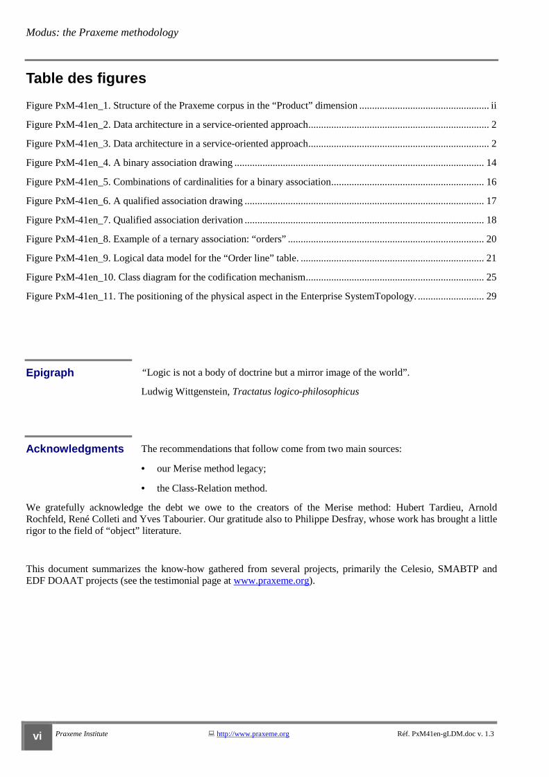
“ Logic is not a body of doctrine but a mirror image of the world”.
Ludwig Wittgenstein, Tractatus logico-philosophicus
The recommendations that follow come from two main sources:
• our Merise method legacy;
• the Class-Relation method.
We gratefully acknowledge the debt we owe to the creators of the Merise method: Hubert Tardieu, Arnold Rochfeld, René Colleti and Yves Tabourier. Our gratitude also to Philippe Desfray, whose work has brought a little rigor to the field of “object” literature.
This document summarizes the know-how gathered from several projects, primarily the Celesio, SMABTP and EDF DOAAT projects (see the testimonial page at www.praxeme.org).
Epigraph
Acknowledgments

Guide PxM-41en « Deriving the logical data model from the business model »
Réf. PxM41en-gLDM.doc v. 1.3 Praxeme Institute � +33 (0)6 77 62 31 75 � [email protected] 1
Introduction
Deriving the LDM from upstream models
This document capitalizes on database design, based on an object model. It aims to provide a synthesis of the rules which enable the transition from an object-oriented business model to a logical relational data model. The business models which will be derived are:
� the semantic model, of course, primarily a model of the “business objects”;
� the pragmatic model, at least the parts which represent objects of the organization.
The derived rules presented here take us from a class model to a logical relational data model (LDM). Other database management systems (DBMS) are not discussed in this document.
The philosophy behind the Praxeme methodology is based on the separation of concerns (cf General Guide PxM-02).
The LDM design begins with: � the semantic model, primarily in the form of class models; � the pragmatic model, if it includes a class model describing the activity (actor, role, authorization, structure,
dossier and other activity objects).
This limitation to the class model can be explained by the design aim: focusing on persistent data, it only deals with the static elements of the model. However, it will be necessary to consider the presence of a state machine and to ensure its persistency.
Derivation is key to data design. This guidance complies with the MDA2 standard. Semantic and pragmatic models abstract away technologies. A glimpse of the technical choices to be made appear with the LDM: at the very least, it needs to take into account
the style of the DBMS chosen. In this case, it will be a simple relational DBMS.
Details about the vendor, version and DBMS possibilities are technology specific. They will condition the physical data model design. Resulting from database optimization, the physical data model design will be mentioned in the last section of this document, but remains outside the scope of this paper.
The need for an LDM has, on occasion, been the subject of debate. Why not directly generate this last stage of the chain – the physical data model? Because many decisions concerning the data model can be taken independently from technical considerations, at
a logical level. This means the model will be useable on a wider scale.
Why yet another data model within the logical aspect, in addition to the service and data flow models? Because these models, while close structurally, meet different requirements. Their design and optimization rules may differ. In addition, the LDM is an essential tool for dealing with themes such as data historization and integrity, which the semantic model may have put to one side.
2 MDA: Model Driven Architecture, a standard defined by the Object Management Group (OMG), which recommends separating models. Upstream models or platform-independent models (PIM) are independent from technical choices and, as such, are fairly stable and transportable into several systems. Platform-specific models (PSM), are derived from PIM by implementing certain technical choices.
Principle
Upstream Aspects
The need for an LDM
Document Objectives
Downstream Aspects
Modus: the Praxeme methodology
2 Praxeme Institute � http://www.praxeme.org Réf. PxM41en-gLDM.doc v. 1.3
Guidance for data architecture
Service is the only means of access to information
It is appropriate that this document only focuses on the relational style, limited to standard SQL. However, with regards to inheritance, the possibilities of an extended
relational model are mentioned, without going into detail about the advanced possibilities of the RDBMSs on the marketplace. In order to do so, we would need to take stock of those derivation rules which exploit these possibilities, in what could be defined as the “extended relational” style.
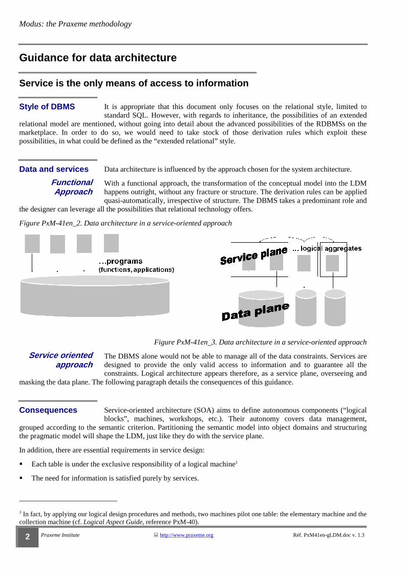
Data architecture is influenced by the approach chosen for the system architecture.
With a functional approach, the transformation of the conceptual model into the LDM happens outright, without any fracture or structure. The derivation rules can be applied quasi-automatically, irrespective of structure. The DBMS takes a predominant role and
the designer can leverage all the possibilities that relational technology offers.
Figure PxM-41en_2. Data architecture in a service-oriented approach
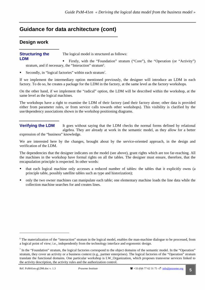
Figure PxM-41en_3. Data architecture in a service-oriented approach
The DBMS alone would not be able to manage all of the data constraints. Services are designed to provide the only valid access to information and to guarantee all the constraints. Logical architecture appears therefore, as a service plane, overseeing and
masking the data plane. The following paragraph details the consequences of this guidance.
Service-oriented architecture (SOA) aims to define autonomous components (“logical blocks”, machines, workshops, etc.). Their autonomy covers data management,
grouped according to the semantic criterion. Partitioning the semantic model into object domains and structuring the pragmatic model will shape the LDM, just like they do with the service plane.
In addition, there are essential requirements in service design:
� Each table is under the exclusive responsibility of a logical machine3
� The need for information is satisfied purely by services.
3 In fact, by applying our logical design procedures and methods, two machines pilot one table: the elementary machine and the collection machine (cf. Logical Aspect Guide, reference PxM-40).
Style of DBMS
Data and services
Functional Approach
Service oriented approach
Consequences

Guide PxM-41en « Deriving the logical data model from the business model »
Réf. PxM41en-gLDM.doc v. 1.3 Praxeme Institute � +33 (0)6 77 62 31 75 � [email protected] 3
These rules banish all direct access to the database, with the exception of the data-owning logical machines.
If we push SOA logic to the extreme, what we are looking to do, is to develop autonomous, logical components. In Praxeme terms, the “logical workshop” corresponds to what will be the deployment unit, in the physical aspect. When a
workshop acts as an autonomous component, it means that the software deriving from it, can be taken and placed on one node or another of the hardware architecture. At the very least, therefore, the workshop needs to take its data resources with it. The consequence is this: in a radical SOA approach, databases are partitioned according to the logical architecture and defined by the boundaries of the logical workshops. This leads to basic schemas being reduced to a few tables. The perimeter of these basics is limited to that of the logical workshops.
Without going so far, we can continue with data architecture habits but introduce larger schemas, sized in accordance to the factories. However, even in this case, we should prohibit any manipulations which go beyond individual workshops and refuse all joins between tables, which are dependent on different workshops. Joins are permitted within logical workshops, but prohibited between workshops. They should be replaced by service calls, which separate the workshops and let them evolve independently.
Radical SOA Approach

Modus: the Praxeme methodology
4 Praxeme Institute � http://www.praxeme.org Réf. PxM41en-gLDM.doc v. 1.3
Guidance for data architecture (cont)
How to size the database
The intention is to develop sufficiently autonomous components in order to facilitate deployment. Indeed, the logical architecture prepares the system in view of a complex deployment. It is not enough to think about the IT system in an organization, you need
to anticipate building a system of systems, which incorporate partner systems together, in a coherent manner4.
At the logical level, the deployment unit is the “logical workshop”, i.e., the aggregate of the intermediary level, between the “logical factory” (equivalent in size to a “domain”) and the “logical machine” (assembly of atomic services)5.
An extreme implementation of the SOA approach would campaign for the scope of databases to be defined by the scale of the logical workshops. In so doing, the workshop would constitute a perfect deployment unit, taking with it both data and processes. Obviously, this option considerably fragments the data architecture. Its validity depends on the level of detail selected for the workshop: if the workshops are too small, limited say to one or two tables, the scale will no longer be compatible with that of a database.
Even without falling into this trap, this option of data architecture does not fully exploit the RDBMS technology; it reduces the scope of the joins and the integrity constraints.
Less radical, the intermediary option chooses the logical factory as the perimeter for database definition. This is fairly common practice, where the notion of domain defines the database. However, there are several, noticeable changes:
� The semantic model is structured by object domain, not functional domains. The architecture graph is therefore different. Even the data definition changes: this is obvious in the case of generic notions, such as “person”.
� The problem of non-redundant data and of reuse, leads to an aspirational, ideal architecture, where a piece of data would only occur once (e.g., “address”, be it of a client, a stakeholder or an expert; or “object” insured or damaged).
The previous options shatter typical data architecture design. They raise the question of joins and long-range constraints, that can no longer be entrusted to the DBMS. More difficult still, is the question of distributed transactions. Indeed, when the data model is
built to correspond to the service model, the functional transactions are more likely to be spread across several databases.
4 We talk of inter-organizational information systems: IOIS.
5 For more information about these notions, please refer to the Logical Aspect Guide, PxM-40.
Scale of the database
Extreme option
Intermediary option
Downgraded option
Guide PxM-41en « Deriving the logical data model from the business model »
Réf. PxM41en-gLDM.doc v. 1.3 Praxeme Institute � +33 (0)6 77 62 31 75 � [email protected] 5
Guidance for data architecture (cont)
Design work
The logical model is structured as follows:
� Firstly, with the “Foundation” stratum (“Core”), the “Operation (or “Activity”) stratum, and if necessary, the “Interaction” stratum6.
� Secondly, in “logical factories” within each stratum7.
If we implement the intermediary option mentioned previously, the designer will introduce an LDM in each factory. To do so, he creates a package for the LDM in the factory, at the same level as the factory workshops.
On the other hand, if we implement the “radical” option, the LDM will be described within the workshop, at the same level as the logical machines.
The workshops have a right to examine the LDM of their factory (and their factory alone; other data is provided either from parameter rules, or from service calls towards other workshops). This visibility is clarified by the use/dependency associations shown in the workshop positioning diagrams.
It goes without saying that the LDM checks the normal forms defined by relational algebra. They are already at work in the semantic model, as they allow for a better
expression of the “business” knowledge.
We are interested here by the changes, brought about by the service-oriented approach, in the design and verification of the LDM.
The dependencies that the designer indicates on the model (see above), grant rights which are too far-reaching. All the machines in the workshop have formal rights on all the tables. The designer must ensure, therefore, that the encapsulation principle is respected. In other words:
� that each logical machine only accesses a reduced number of tables: the tables that it explicitly owns (a principle table, possibly satellite tables such as type and historization);
� only the two owner machines can manipulate each table; one elementary machine loads the line data while the collection machine searches for and creates lines.
6 The materialization of the “interaction” stratum in the logical model, enables the man-machine dialogue to be processed, from a logical point of view; i.e., independently from the technology interface and ergonomic design.
7 In the “Foundation” stratum, the logical factories correspond to the object domains of the semantic model. In the “Operation” stratum, they cover an activity or a business context (e.g., partner enterprises). The logical factories of the “Operation” stratum translate the functional domains. One particular workshop is LW_Organization, which proposes transverse services linked to the activity description, the activity rules and the authorization control.
Structuring the LDM
Verifying the LDM
Modus: the Praxeme methodology
6 Praxeme Institute � http://www.praxeme.org Réf. PxM41en-gLDM.doc v. 1.3
Summary of data related decisions
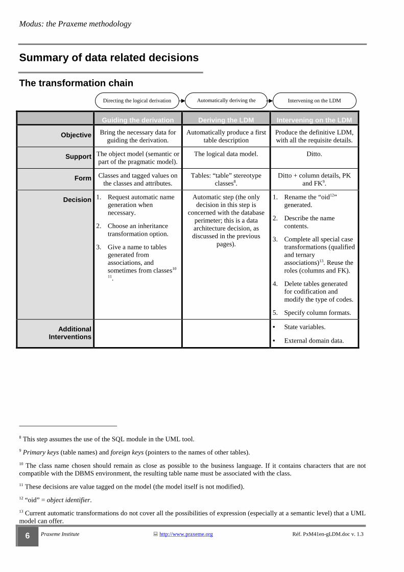
The transformation chain
Guiding the derivation Deriving the LDM Intervening on the LDM
Objective Bring the necessary data for guiding the derivation.
Automatically produce a first table description
Produce the definitive LDM, with all the requisite details.
Support The object model (semantic or part of the pragmatic model).
The logical data model. Ditto.
Form Classes and tagged values on the classes and attributes.
Tables: “table” stereotype classes8.
Ditto + column details, PK and FK9.
Decision 1. Request automatic name generation when necessary.
2. Choose an inheritance transformation option.
3. Give a name to tables generated from associations, and sometimes from classes10
11.
Automatic step (the only decision in this step is
concerned with the database perimeter; this is a data architecture decision, as discussed in the previous
pages).
1. Rename the “oid12” generated.
2. Describe the name contents.
3. Complete all special case transformations (qualified and ternary associations)13. Reuse the roles (columns and FK).
4. Delete tables generated for codification and modify the type of codes.
5. Specify column formats.
Additional Interventions
• State variables.
• External domain data.
8 This step assumes the use of the SQL module in the UML tool.
9 Primary keys (table names) and foreign keys (pointers to the names of other tables).
10 The class name chosen should remain as close as possible to the business language. If it contains characters that are not compatible with the DBMS environment, the resulting table name must be associated with the class.
11 These decisions are value tagged on the model (the model itself is not modified).
12 “oid” = object identifier.
13 Current automatic transformations do not cover all the possibilities of expression (especially at a semantic level) that a UML model can offer.
Directing the logical derivation Automatically deriving the LDM
Intervening on the LDM

Guide PxM-41en « Deriving the logical data model from the business model »
Réf. PxM41en-gLDM.doc v. 1.3 Praxeme Institute � +33 (0)6 77 62 31 75 � [email protected] 7
Summary of data related decisions (cont)
Distribution of decisions
Theme Semantic Aspect Logical Aspect Physical Aspect
Persistency Class and attribute persistency are decided from the semantic
model14.
We can decide to stock the derived attributes in table
form15.
Generation and optimization of the physical schema of the
database (DDL16).
Identification Among class properties, it is possible that some will
already have names17,and be listed as such. But, artificial
names, with no semantic value, are never listed in the
semantic model.
Prospective name properties are picked up again by
primary keys in the LDM. Tables, derived from classes without names, are given an
artificial name.
In all scenarios, the designer is responsible for defining
name content and composition.
The automatic counter (physical name for the table
lines) can be used as an identification solution.
Inheritance The semantic model uses inheritance to arrange
concepts into classifications.
The target DBMS style can include a natural inheritance solution18. If not, inheritance
trees are transformed according to one of the
possible options, on a case-by-case basis19.
Optimization provides better links between the tables
implicated in classification.
14 In business informatics, data described in the form of attributes in the semantic model is almost always persistent. By default, modeling tools designate classes and attributes as persistent.
15 Derived attributes (in a UML sense), behave as operations: their values are obtained by calculation or navigation (e.g., a person's age – obtained using the date of birth). A normalized LDM would not retain these attributes as it would mean introducing functional dependency amongst the data. Concerned with optimization, the designer may decide, however, to list the attribute in the storage support, in column form. This solution is mainly of interest when the derived attribute produces consolidated data (calculations on groups of objects) or when it requires complex navigation.
16 DDL: Data Definition Language. These are the “create table”, etc.
17 We are talking about “properties”: these can be attributes of course, or operations. For example, the social security number should be restored using an operation or, better still, a derived attribute, aggregating part of the date of birth, the sex, etc. In this way, functional dependency is avoided. The number's ability to identify the person is, of course, retained.
18 Extended relational technology or relational object technology provide an inheritance solution, by defining types and subtypes.
19 See further on in this document.
Modus: the Praxeme methodology
8 Praxeme Institute � http://www.praxeme.org Réf. PxM41en-gLDM.doc v. 1.3
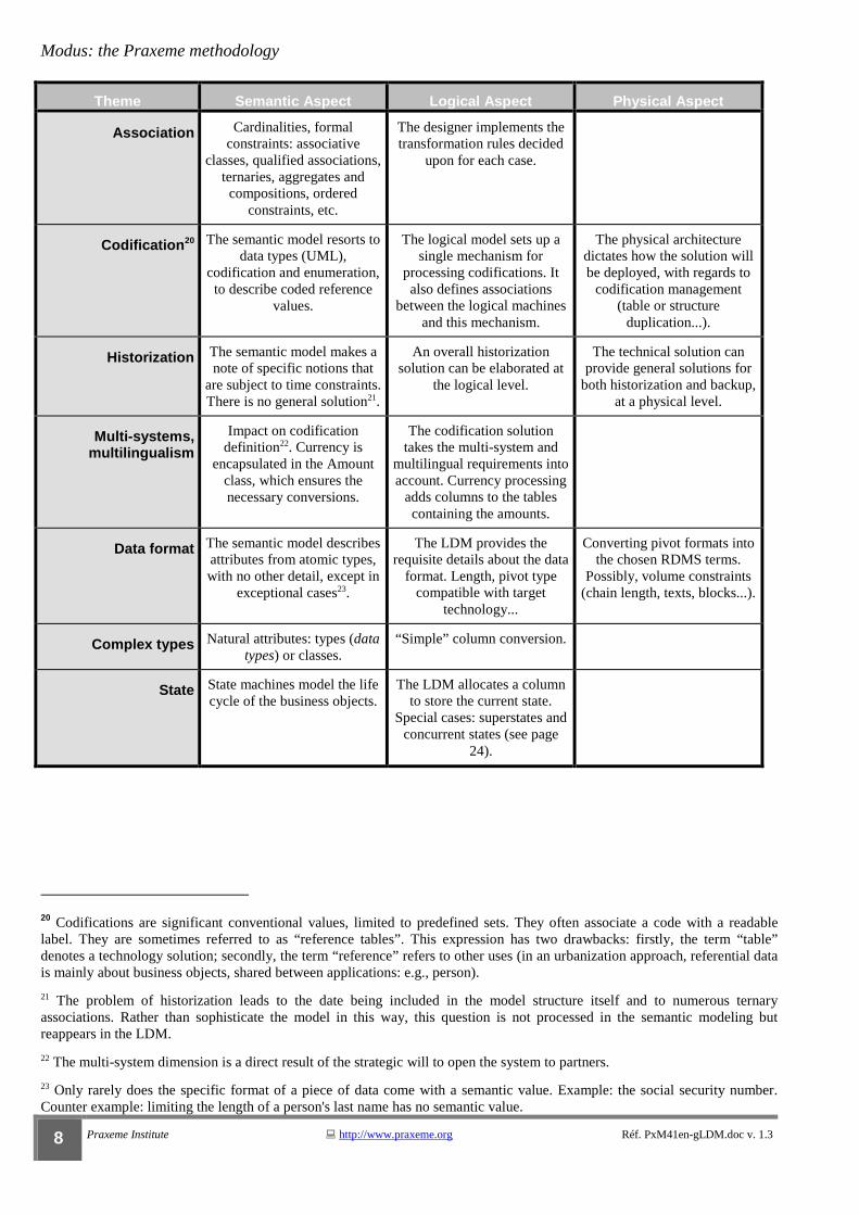
Theme Semantic Aspect Logical Aspect Physical Aspect
Association Cardinalities, formal constraints: associative
classes, qualified associations, ternaries, aggregates and compositions, ordered
constraints, etc.
The designer implements the transformation rules decided
upon for each case.
Codification20 The semantic model resorts to data types (UML),
codification and enumeration, to describe coded reference
values.
The logical model sets up a single mechanism for
processing codifications. It also defines associations
between the logical machines and this mechanism.
The physical architecture dictates how the solution will be deployed, with regards to
codification management (table or structure
duplication...).
Historization The semantic model makes a note of specific notions that
are subject to time constraints. There is no general solution21.
An overall historization solution can be elaborated at
the logical level.
The technical solution can provide general solutions for
both historization and backup, at a physical level.
Multi-systems, multilingualism
Impact on codification definition22. Currency is
encapsulated in the Amount class, which ensures the necessary conversions.
The codification solution takes the multi-system and
multilingual requirements into account. Currency processing
adds columns to the tables containing the amounts.
Data format The semantic model describes attributes from atomic types, with no other detail, except in
exceptional cases23.
The LDM provides the requisite details about the data
format. Length, pivot type compatible with target
technology...
Converting pivot formats into the chosen RDMS terms.
Possibly, volume constraints (chain length, texts, blocks...).
Complex types Natural attributes: types (data types) or classes.
“Simple” column conversion.
State State machines model the life cycle of the business objects.
The LDM allocates a column to store the current state.
Special cases: superstates and concurrent states (see page
24).
20 Codifications are significant conventional values, limited to predefined sets. They often associate a code with a readable label. They are sometimes referred to as “reference tables”. This expression has two drawbacks: firstly, the term “table” denotes a technology solution; secondly, the term “reference” refers to other uses (in an urbanization approach, referential data is mainly about business objects, shared between applications: e.g., person).
21 The problem of historization leads to the date being included in the model structure itself and to numerous ternary associations. Rather than sophisticate the model in this way, this question is not processed in the semantic modeling but reappears in the LDM.
22 The multi-system dimension is a direct result of the strategic will to open the system to partners.
23 Only rarely does the specific format of a piece of data come with a semantic value. Example: the social security number. Counter example: limiting the length of a person's last name has no semantic value.

Guide PxM-41en « Deriving the logical data model from the business model »
Réf. PxM41en-gLDM.doc v. 1.3 Praxeme Institute � +33 (0)6 77 62 31 75 � [email protected] 9
Prerequisite work on the semantic model
Logical considerations must not flow back into semantics
The transformation chain anticipates interventions on the semantic model. Without these interventions, the transformation into the logical data model would not work.
However, these interventions are only allowed if they do not alter the structure of the semantic model. Tagged values are introduced in the modeling tool, by means of a UML profile, for example.
The following data will guide the derivation of the class model to the LDM:
� desired persistency of the class or attribute (this decision is a semantic one); � table names, should reusing the name of the modeling element (class or association) be unsuitable24; � option for inheritance transformation (this is discussed later on); � request for automatic “OID” (object identifiers) generation.
Generating an LDM will only work if each class has an object identifier. In the absence of an identifier, connections between tables (foreign keys) cannot be built. In the
semantic model, there are two ways of preparing the identifiers for the LDM tables:
1. The class can contain one or more identifying attributes. These are the natural class properties which take a distinctive value for each object. Artificial attributes, which may have been created to identify the objects are, of course, eliminated. They have no place in the semantic model25.
2. If a class has no naturally identifying property, the database modeler will, by tagged value, request that an OID be automatically generated. The resulting column will then be defined by the designer, on the LDM.
Interlinked classes are only used in the semantic model, by the modeler, for classification purposes, to facilitate the operating of the model. This “rogue” use of
interlinked classes creates problems when generating the LDM. Interlocked classes have a specific meaning, linked to programming languages. It is therefore necessary to delete them from the semantic model or, if this is not an option, to specify the derivation required in this case.
24 This case systematically arises when we make rules about naming tables. As for the semantic model, it favors the readability and restitution of the spoken word. At a bare minimum, it is necessary to name the tables which correspond to associations. Indeed, associations are almost always named with a verb, conjugated in the present simple, in order to recreate the spoken phrases.
25 Limited case scenario: in data management, lots of numbers (client, file...) have the role of artificial identifier. When the modeler has been given a mandate to innovate the semantics, he removes these numbers from the semantic model. In analysis (observation without intervention), as far as these properties are known to the actors of the system, the modeler can put them back into the model.
Principle
Logical data
Identification
Embedded classes

Modus: the Praxeme methodology
10 Praxeme Institute � http://www.praxeme.org Réf. PxM41en-gLDM.doc v. 1.3
Prerequisite work on the semantic model (cont)
Additional comments
The Amount class encapsulates currency processing.
Its attributes are private and the data is only used by those operations incorporating a currency definition parameter, activated by the person making the request.
It is wise to keep the value date, which could be necessary for conversions. The rest of the model can refer to the Amount class, as an atomic type, without going through an association.
Deriving the LDM from the semantic model transforms the Amount type attributes into three columns: value, currency code and value date.
The currency code refers back to the codification table.
Naming conventions can take the attribute name for the first column; “cd_currency” and “dt_value” can be then added to this name.
Currency
Guide PxM-41en « Deriving the logical data model from the business model »
Réf. PxM41en-gLDM.doc v. 1.3 Praxeme Institute � +33 (0)6 77 62 31 75 � [email protected] 11
Deriving the LDM from the semantic model
General Points
The passage from the semantic model to the logical model needs to remain as easy to read as possible. The designer, therefore, limits the transformations made on model
element names (class names which become table names; attribute names which become column names...). Derivation exploits not only class and attribute names, but also the role and qualifier names found on the associations.
At a project level, or even better, at an IT departmental level, naming conventions are established. For example:
� “TB_”: prefix for table names;
� “id_”: prefix for identifiers;
� “cd_”: prefix for codes;
� “FK_”: for “foreign key”;
� “PK_”: for “primary key” (generated by the tool, but not kept as column name).
In this example, upper case letters are used for table names; lower case letters for column names.
Aside from the conventions mentioned above, the LDM element names must comply with the following conditions:
� They comply with standard SQL (no use of reserved SQL words; special characters are deleted).
� They do not interfere with the automatic generation by the SQL module of the UML tool (surprises are not unknown here).
Table names do not have to reflect machine names. The LDM and the service model can be disassociated.
Main directive
Conventions
Naming constraints
Modus: the Praxeme methodology
12 Praxeme Institute � http://www.praxeme.org Réf. PxM41en-gLDM.doc v. 1.3
Deriving the LDM from the semantic model (cont)
Deriving inheritance
The extended relational DBMS incorporates mechanisms which are like object logic. The notion of subtable provides an elegant and direct solution to inheritance. A table corresponding to the parent class is created, followed by as many subtables as there are
subclasses.
This facility is, however, rarely authorized by IT managers, afraid that they will not be able to master its behavior, or who have simply not taken the time to evaluate it.
When we abstain from using the typing proposed by the DBMS, the inheritance present in the business model (semantic or pragmatic) must be transformed and flattened in the tables.
There are three options for this transformation: � one table per class; � one table per concrete class; � one table for the group of classes.
In the first option, as many tables as there are classes in the inheritance tree are defined – be they concrete or abstract classes26.
This option is the most rigorous one, as it avoids attribute redundancy and respects the first normal form: each column receives one, and only one, value for all the lines in the table.
This comes at a cost: the number of tables and the associations between these tables. All of these tables maintain associations which reproduce the inheritance tree. These associations are materialized by foreign keys on the identifier. The identifier is first defined in the table corresponding to the root class. All the other tables possess the same identifier.
A column must be added to the root table, to indicate the type of occurrences. The value of this column will enable the object data to be put back together, by exploring the “subtables” associated with this type. Indeed, the data can be spread across several tables, if the classification is on several levels.
The intermediary option enables the number of tables, where the inheritance tree contains abstract classes, to be reduced.
To compensate: � Attributes of parent classes are translated into columns, which are duplicated across several tables. Hence the
structural redundancy. � Associations at the top levels of the inheritance tree must be “brought down” across several tables, which
complicates the data model.
When the subclasses carry relatively few attributes, and when a high proportion of attributes are common to the concrete classes, it is tempting to group the data together in one single table.
26 A class is said to be “concrete” when it can be instantiated (objects are created from it); in the opposite scenario, it is said to be “abstract”. Inheritance root classes are often abstract, but this is not always the case. Whatever the level of inheritance, a class can be concrete. On the other hand, a leaf class of the inheritance tree, has no reason to be abstract when the model is finished.
Extended relational model
Three classical options
One table per class
On table per concrete class
One single table

Guide PxM-41en « Deriving the logical data model from the business model »
Réf. PxM41en-gLDM.doc v. 1.3 Praxeme Institute � +33 (0)6 77 62 31 75 � [email protected] 13
This option does not respect the first standard form, as columns translating the attributes of the subclasses will not be fed by all the occurrences. This makes saving Boolean attributes complicated. However, for the rest, this solution simplifies the data model.
This discussion shows that there is no one option that can be implemented across the board. The designer decides on a case-by-case basis, weighing up the advantages and the disadvantages:
� What proportion of common attributes are there, compared to specific attributes (parent/child classes)?
� Are there a lot of associations and how are they connected to the inheritance tree classes?
� Do we accept the required normalization and sophistication for Boolean values?
� What type of queries will we need to build?
Option one (a table per class), for all its rigor, requires very sophisticated queries to be built. This is not necessarily insurmountable, as this complexity is masked by the logical machine which owns the tables.
In all instances, where the LDM does not translate the inheritance tree as is, it is necessary to define the occurrence type. In most cases, this leads to a type column
being added (a subclass), which enables the integrity of the data to be verified. Only the columns meaningful for the type should be filled in. The type can be processed like a codification (code plus label).
For any given inheritance tree, the designer appreciates the above-mentioned criteria. If the tree is extended (wide and deep), the designer can combine the options: e.g., cover several concrete classes by a single table, while processing the rest as in option one.
This work should be done on a case-by-case basis.
Although the transformation logic for inheritance also occurs for logical machines, data-related and service-related decisions are independent. Structural and formality requirements differ for both. For example, optional data is tolerated more easily in a service contract than in the LDM.
Criteria of choice
Type
Intermediary solutions

Modus: the Praxeme methodology
14 Praxeme Institute � http://www.praxeme.org Réf. PxM41en-gLDM.doc v. 1.3
Deriving the LDM from the semantic model (cont)
Deriving associations
We would like to keep, in the upstream models (logical and others), as much of the semantic as possible, protecting the capacities of expression freed up during the semantic modeling. This applies to both data and service models. The following two
paragraphs provide answers to this aspiration.
The derived table comes from either a class or an association. In the case of a class, the table can take the name of the class as it is, or by adding a prefix (e.g., TB),
which avoids potential confusion during discussions.
In the case of an association, the name is not directly derived. Indeed, our semantic modeling rules give preference to verbs conjugated in the present simple to name associations. The concern here is to restore the business language and to make the model readable. For example, the Claim (class) affects (association) an Object (class).
It would not be very becoming to name tables after the verb. Better to prefer a name which can be obtained from the verb in a substantive way.27
Columns containing foreign keys should be named by role names, when they exist on the association. Thus, when table TB_B contains a foreign key to table TB_A, the most significant name for this column is the association role name, on the class A side.
In the figure below, it is “A's role”. For example, “client”, Person role in a Contract association.
Figure PxM-41en_4. A binary association drawing
Logical architecture and the partitioning in object domains at the semantic level, introduce constraints for the logical data model. The LDM has to take note of them (see § on data architecture). These architecture constraints prevail over the
transformation rules hereafter.
27 This name is introduced, before derivation, in the form of a tagged value attached to the association, by the SQL module of the UML tool. The interest in value tagging the business model, lies in keeping the decisions as well as the possibility of generating the data model several times.
Exploiting semantics
Association orientation
A B << association name >>A’s role B’s role
min1..max1 min2..max2
Table name
Roles
Guide PxM-41en « Deriving the logical data model from the business model »
Réf. PxM41en-gLDM.doc v. 1.3 Praxeme Institute � +33 (0)6 77 62 31 75 � [email protected] 15
Deriving the LDM from the semantic model (cont)
Deriving binary associations
Binary associations are derived according to the same rules formalized by the Merise method (passage from the CDM to the LDM) or the entity-relation methods. They are covered by the following paragraphs, but only apply if they do not violate the
association guidance.
This rules take the cardinality of the association into account. In the figure on the previous page, min1 and max1 represent, respectively, the minimum and maximum number of Class A instances that can be linked, through association, to the same instance in Class B. Cardinalities can take the usual values, noted in UML as “0”, “1” and “*” (for n). They can also be given an absolute value (a real number) or a relative one (a parameter name).
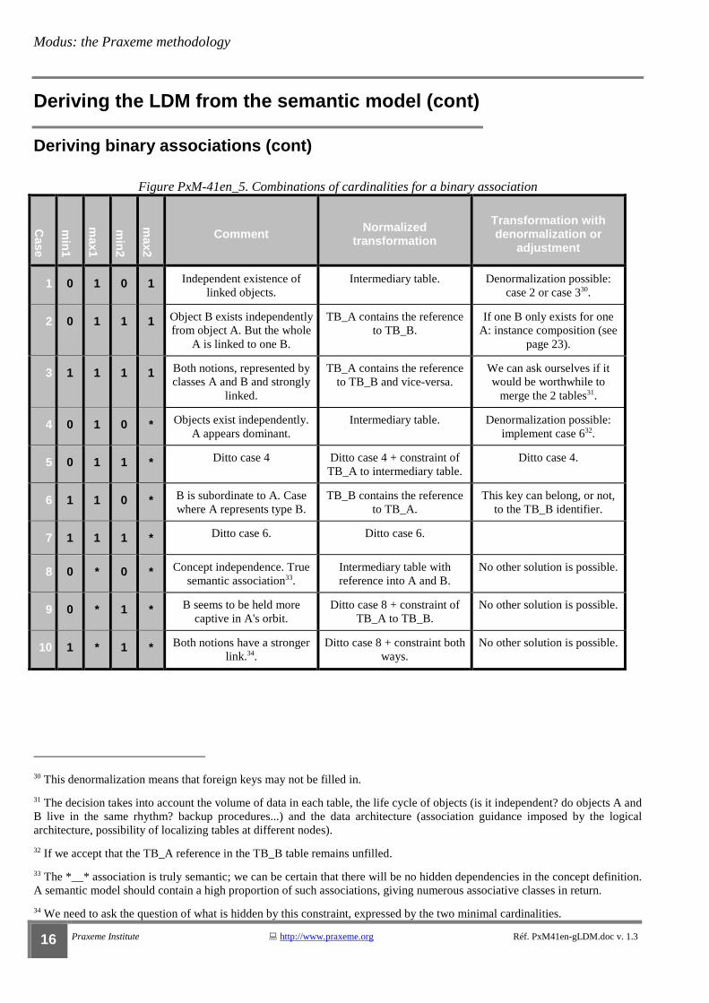
In binary associations, cardinalities are indicated on each branch. Considering the symmetry of the roles, this produces ten combinations, which are listed in the table below.
The following notions are needed to state the rules of derivation.
Normalized transformation keeps the normal forms of the model. The semantic model already implements, at a minimum, the first three normal forms. This formal requirement contributes to the semantic quality of the model. It pushes for the
concepts, which could be hidden among the more encompassing concepts, to be drawn out and isolated.
Evidence to hand, it is possible to “denormalize” the data model. The price to be paid is with the introduction of dependency or redundancy and, more often than not, the authorization of having columns which are not filled in.
Note that for some weakly semantic attributes (informative fields, comments, optional fields...), the class model often does not strictly follow the first normal form28.
The “intermediary table”, mentioned in the table below, is the association table which ensures the connection between the two business tables. It contains a foreign key to each of the linked tables. The intermediary table identifier – the primary key – is
obtained by concatenating the foreign keys. This step verifies the association definition, which forbids the same couple from being saved several times.
This definition and the construction apply, irrespective of the arity29 of the association.
28 The first normal form (1NF) stipulates that every attribute must have one, and only one, value for each instance and each moment of its existence.
29 The arity of an association is the number of branches. Its minimal value is 2, because even with reflexive associations, there are two roles. In theory, there is no maximal value. In practice, the majority of associations are binary, especially in cases where the semantic modeling has not been brought to fruition. Semantic modeling has to draw out the determination of concepts. This means resorting to n-ary associations.
Ordinary binary associations
Cardinalities
Combinations
Derivation
Normalized transformation
Denormalization
The intermediary table or relation)
Modus: the Praxeme methodology
16 Praxeme Institute � http://www.praxeme.org Réf. PxM41en-gLDM.doc v. 1.3
Deriving the LDM from the semantic model (cont)
Deriving binary associations (cont)
Figure PxM-41en_5. Combinations of cardinalities for a binary association
Case
min
1
max1
min
2
max2
Comment Normalized transformation
Transformation with denormalization or
adjustment
1 0 1 0 1 Independent existence of linked objects.
Intermediary table. Denormalization possible: case 2 or case 330.
2 0 1 1 1 Object B exists independently from object A. But the whole
A is linked to one B.
TB_A contains the reference to TB_B.
If one B only exists for one A: instance composition (see
page 23).
3 1 1 1 1 Both notions, represented by classes A and B and strongly
linked.
TB_A contains the reference to TB_B and vice-versa.
We can ask ourselves if it would be worthwhile to
merge the 2 tables31.
4 0 1 0 * Objects exist independently. A appears dominant.
Intermediary table. Denormalization possible: implement case 632.
5 0 1 1 * Ditto case 4 Ditto case 4 + constraint of TB_A to intermediary table.
Ditto case 4.
6 1 1 0 * B is subordinate to A. Case where A represents type B.
TB_B contains the reference to TB_A.
This key can belong, or not, to the TB_B identifier.
7 1 1 1 * Ditto case 6. Ditto case 6.
8 0 * 0 * Concept independence. True semantic association33.
Intermediary table with reference into A and B.
No other solution is possible.
9 0 * 1 * B seems to be held more captive in A's orbit.
Ditto case 8 + constraint of TB_A to TB_B.
No other solution is possible.
10 1 * 1 * Both notions have a stronger link.34.
Ditto case 8 + constraint both ways.
No other solution is possible.
30 This denormalization means that foreign keys may not be filled in.
31 The decision takes into account the volume of data in each table, the life cycle of objects (is it independent? do objects A and B live in the same rhythm? backup procedures...) and the data architecture (association guidance imposed by the logical architecture, possibility of localizing tables at different nodes).
32 If we accept that the TB_A reference in the TB_B table remains unfilled.
33 The *__* association is truly semantic; we can be certain that there will be no hidden dependencies in the concept definition. A semantic model should contain a high proportion of such associations, giving numerous associative classes in return.
34 We need to ask the question of what is hidden by this constraint, expressed by the two minimal cardinalities.

Guide PxM-41en « Deriving the logical data model from the business model »
Réf. PxM41en-gLDM.doc v. 1.3 Praxeme Institute � +33 (0)6 77 62 31 75 � [email protected] 17
Deriving the LDM from the semantic model (cont)
Special features of associations
An association is “reified”35 when a class is associated with it. This is known as an “associative class” 36.
When an association is reified and the associative class contains attributes, an intermediary table is derived from it, irrespective of the cardinalities of the association.
The table name takes the associative class name (and not the association name).
When the association carries a qualifier, there are new derivation possibilities; the qualifier must be placed on a table. In general, the qualifier will reduce the cardinality opposite (on the B side shown in the figure below).
Figure PxM-41en_6. A qualified association drawing
Depending on the cardinality combinations, there are three types of solution available to find the data carried by the qualifier:
1. The intermediary table,37 carrying the identifiers, as well as a column corresponding to the qualifier.
2. One of the tables receives the qualifier, which is valorized on each line, as well as a foreign key to the other table.
3. The structure of the TB_A table contains the foreign keys for all of the qualifier values. This structure can be in a table format, with as many positions as there are qualifier values. If table formats are not possible, the table itself will contain as many columns as there are qualifier values; all these columns are foreign keys to TB_B.
In the case where several qualifiers would be on the A side, the intermediary table contains as many columns as qualifiers. The second solution is adjusted in the same way. The third solution works only with multidimensional table formats.
35 “Reification” is a term which comes from Medieval philosophy (from the Latin “res facere”, literally “to make a thing”). This term has taken on a new meaning in modeling methods (cf. Jacques Ferber). Reification is the essential act of modeling: the modeler takes the decision to isolate part of what is real, in order to represent it in the class category.
36 In the Merise method, this was known as the “surrogate association”. UML (and the object method in general) brings two notable changes: firstly, this associative class can carry both operations and attributes; secondly, it is possible to link this class by associations (the association of associations was not possible in the Merise method).
37 Cf. definition page 15.
Reified Associations
Derivation
Qualified associations
A broad outline of the solution
A B qualifier
min1..max1 min2..max2
<< association name >>

Modus: the Praxeme methodology
18 Praxeme Institute � http://www.praxeme.org Réf. PxM41en-gLDM.doc v. 1.3
Deriving the LDM from the semantic model (suite)
Derivation rules for qualified associations
The table below details the derivation rules for binary qualified associations. They occur more frequently, as the qualifier breaks the symmetry of the association.
The solutions mentioned in the table are:
1. The intermediary table carries the qualifier(s).
2. One of the tables contains a column giving the qualifier value, and another containing the foreign key. If there are several qualifiers: as many columns as qualifiers are needed, but only one foreign key.
3. A structure which reflects the qualifier values and contains the references to the other table.
Generally, the qualifier takes a fixed number of values (an enumerated type, a position in a finite domain...). If this is not the case (real, date...), solution 3 is not possible.
Figure PxM-41en_7. Qualified association derivation
Case
min
1
max1
min
2
max2
Normalized transformation
Transformation with denormalization or
adjustment
Complement or alternative
1 0 1 0 1 Intermediary table with a column for the qualifier.
Denormalization possible: case 2
Solutions 1 and 3, if we except unfilled columns.
2 0 1 1 1 TB_A contains n columns, each referencing TB_B.
Solution 3 (table). Solution 1 possible.
3 0 1 0 * Intermediary table with a column for the qualifier.
No other solution possible. Solution 1.
4 0 1 1 * Ditto case 3 + constraint of TB_A to intermediary table.
Ditto. Solution 1.
5 1 1 0 1 TB_B with qualifier attribute and reference TB_A.
The other solutions are possible.
Solution 2. 1 and 3 possible.
6 1 1 1 1 Ditto case 2 + constraint TB_B to TB_A
Solutions 2 and 3 are also conceivable.
If solution 3: a reference to B only exists once.38.
7 1 1 0 * TB_B contains the reference to TB_A and the qualifier.
Transformation 4 may be preferred.
The column name depends on its positioning.
8 1 1 1 * Ditto case 3 + constraint of TB_A to intermediary table.
Solution 1.
9 0 * 0 1 Intermediary table carrying the qualifier.
Denormalization possible: solution 3.
Solution 1 (normalized) or 3.
38 It is not possible to have several occurrences of the same reference to a TB_B line, inside a same TB_A line, even with different qualifier values.
The cases
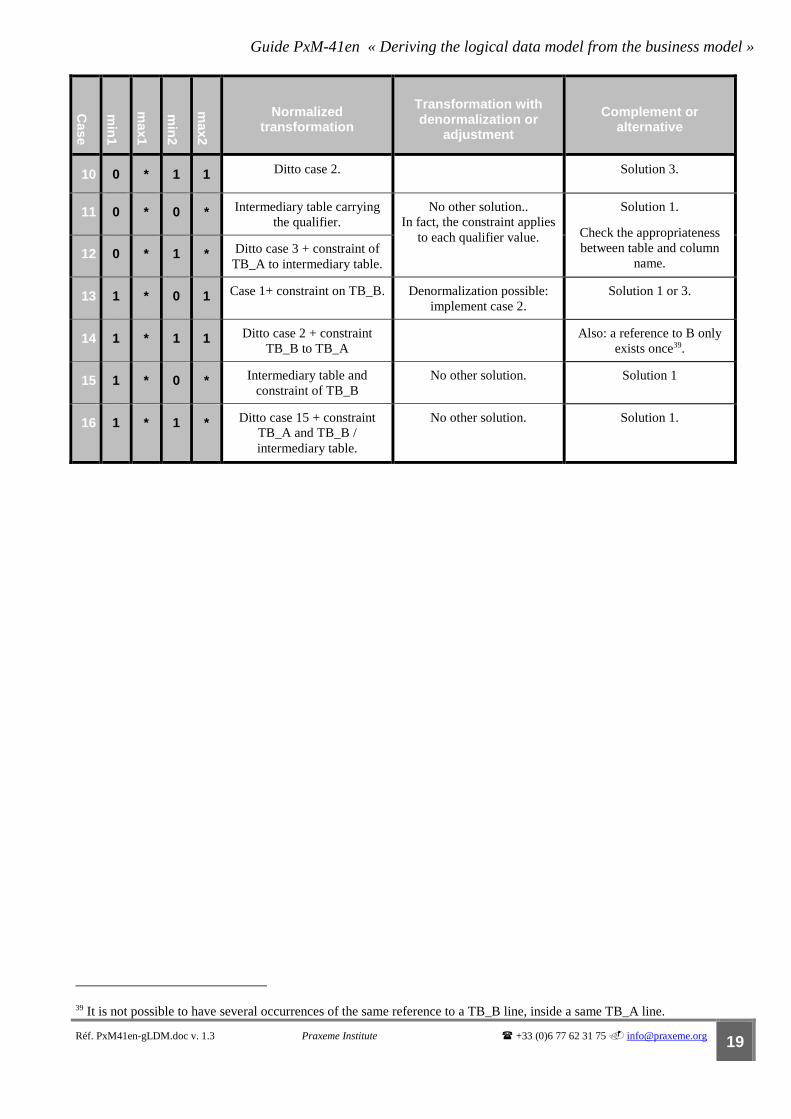
Guide PxM-41en « Deriving the logical data model from the business model »
Réf. PxM41en-gLDM.doc v. 1.3 Praxeme Institute � +33 (0)6 77 62 31 75 � [email protected] 19
Case
min
1
max1
min
2
max2
Normalized transformation
Transformation with denormalization or
adjustment
Complement or alternative
10 0 * 1 1 Ditto case 2. Solution 3.
11 0 * 0 * Intermediary table carrying the qualifier.
No other solution.. In fact, the constraint applies
to each qualifier value.
Solution 1.
Check the appropriateness between table and column
name. 12 0 * 1 * Ditto case 3 + constraint of
TB_A to intermediary table.
13 1 * 0 1 Case 1+ constraint on TB_B. Denormalization possible: implement case 2.
Solution 1 or 3.
14 1 * 1 1 Ditto case 2 + constraint TB_B to TB_A
Also: a reference to B only exists once39.
15 1 * 0 * Intermediary table and constraint of TB_B
No other solution. Solution 1
16 1 * 1 * Ditto case 15 + constraint TB_A and TB_B / intermediary table.
No other solution. Solution 1.
39 It is not possible to have several occurrences of the same reference to a TB_B line, inside a same TB_A line.

Modus: the Praxeme methodology
20 Praxeme Institute � http://www.praxeme.org Réf. PxM41en-gLDM.doc v. 1.3
Deriving the LDM from the semantic model (cont)
Deriving n-ary associations
The most common case is the ternary association: an association that links three classes. The below figure gives an example.
An actor orders an offering (product or service). In so doing, he is considered as a client (as described by the association role). If the model restored this phrase in a binary association, the link between a given actor and a given offering could only be instanced once (it would be the road to ruin!). The correct representation is therefore ternary, introducing the motivation of the act and the date. The “order” class composes the third term of the association.
Figure PxM-41en_8. Example of a ternary association: “ orders”
N-ary associations
Illustration
Actor
Product
Order
Available Stock
Distribution Centre
* *
stores
Sourced Stock
Order Line
**
res erves
Offering
orderedc us tomerorders
motive}{ 1 to 1
*
0..1issuer
issues

Guide PxM-41en « Deriving the logical data model from the business model »
Réf. PxM41en-gLDM.doc v. 1.3 Praxeme Institute � +33 (0)6 77 62 31 75 � [email protected] 21
Deriving the LDM from the semantic model (cont)
Deriving n-ary associations (cont)
It is difficult to show the cardinalties of n-ary associations on class diagrams. James Rumbaugh advises processing them in model comment blocks.
This does not affect derivation as, no matter what the cardinalities of an association are, a table is created for the association.
This intermediary table contains as many foreign keys as there are branches in the association. The table identifier is obtained from the concatenation of these foreign keys.
In the example on the previous page, the ternary association is reified by the concept of order line. The constraint that this association expresses, is that an order can only contain a single line on a given product40.
The class diagram of the previous page, highlights a constraint between Order and Actor. This constraint specifies that all lines pertaining to the same order, can refer to one, and only one, actor.
If we opt for an order identifier relating to the client, implementing the derivation rule mentioned above, will mean doubling the column containing the actor identifier. The resulting model will need to be altered by removing this column.
Thus established, the primary key of the intermediary table is enough to check the integrity constraint.
The figure below illustrates the transformation of the ternary association of the previous model, taking into account the constraint.
Figure PxM-41en_9. Logical data model for the “Order line” table.
idOffering idActor idActornbOrder
idOfferingidActoridActornbOrder
TB_Offering TB_Actor TB_Order
TB_OrderLine
Generally speaking, the order is identified by a number of its own and the problem does not arise.
40 This constraint does not apply to the man-machine interface, which can considerably ease keyboarding, before the data is consolidated.
Derivation
The intermediary table
Associative class case
Taking constraints into consideration
Modus: the Praxeme methodology
22 Praxeme Institute � http://www.praxeme.org Réf. PxM41en-gLDM.doc v. 1.3
Deriving the LDM from the semantic model (cont)
Other class model details
Aggregation is nothing more than an association and, as such, does not require any particular derivation rules. Composition (in its strictest sense41) expresses a stronger constraint: the component dependency with regards to the owner class. This
circumstance prompts the designer to absorb the component data into the owner table. The condition remains the cardinality of the association, on the component side (cf. association rule).
It is possible to mention, on an association branch, the reserved word “ordered”42. It only has a meaning in the case of a multiple cardinality (not necessarily unknown). This constraint stipulates an ordered list of objects.
The derivation leads to a sequence number being added (if one does not already exist) to the place where the links are stored:
� either on the intermediary table (case 1, 4, 8 of the table on page 15);
� or on the corresponding table (case 6 of the same table).
Association derivation: denormalization
In the case of an association whose cardinalities are 0-1__1-1, the normalized derivation is processed by case 2. However, it is possible that when an instance of B is linked to an instance of A, it cannot be linked to anything else. Other instances, not
linked to instances of A, will be able to exist autonomously or depend on other classes. This is the composition of instances.
In this case, the TB_A table could absorb the TB_B table. We are dealing here with a denormalized application, as the same data structure (all the columns derived from class B) will be duplicated: it will be placed into the TB_A table and into other tables, or in a TB_B table, saving the other instances.
This is a limited case scenario, but the reasoning transposes to the data architecture level. B can act as a generic concept, for example Person in the Reality domain. The derived data structure can be duplicated in the LDM of the user factories (“client” domain, “HR” domain...).
41 It is represented on UML class diagrams by a line finished by a black lozenge shape (placed on the owner side, the composite class).
42 Not to be confused with the role name “ordered” used in the diagram on the previous page. This role name expresses a semantic element, whereas the reserved word {ordered} (normally between brackets) is for a structural constraint.
Composition and aggregation
Constraint {ordered}
Composition of instances
Guide PxM-41en « Deriving the logical data model from the business model »
Réf. PxM41en-gLDM.doc v. 1.3 Praxeme Institute � +33 (0)6 77 62 31 75 � [email protected] 23
Deriving the LDM from the semantic model (cont)
Deriving codifications
Semantic class attributes which represent a codification (type or enumeration) are derived in columns of a character chain nature. These columns contain the identifier values on the Codification table (pseudo-identifier id_codification).
See, further on, “Codification mechanism”, page 24. The length of the string is given by this chapter.
The column keeps the code without the language. Indeed, the language in which the codification should be expressed depends on the user context, and not on the object itself.
Deriving state machines
In order to keep the last executed state where the object lodged itself, it is necessary to add a column to the corresponding table.
There are several cases:
• States encompass finer states: in this case, it is possible to either add a second column (one per level of depth in the state machine), or to only keep the detailed values.
• The state machine contains concurrent compartments: in this case, the only solution is to define a column for each of the simultaneous compartments.
• The state machine may have a memory (historization of a state, indicated by an encircled letter “H” on those states which can be historized): an additional column is also needed here.
Sate values are then distributed on the columns. The distribution of values on the columns is no trivial matter. However, only the logical machine has knowledge of the mechanism.
Linking mechanism for Codifications
One or more columns
Modus: the Praxeme methodology
24 Praxeme Institute � http://www.praxeme.org Réf. PxM41en-gLDM.doc v. 1.3
Decisions on the LDM
Codification mechanism
The semantic model mentions codifications in the form of object types, codifications (association of a code and an explicit label), or enumerations (fixed value codifications,
i.e., closed, stable lists).
In all these cases, the data structure is the same, as are the multi-system and multilingual requirements. As a consequence, the logical architecture proposes a unique mechanism which enables transverse services to be reused and avoids multiplying small tables.
Services and data structure are defined in the factory LF_Utilities. This means that the codification mechanism is logically unique and re-useable. The mechanism is in the form of a machine LM_Codification. It is put away in the workshop LW_Thesaurus43.
The vocation of this workshop is to ensure the system comprehension and behavior. It regroups the codifications and messages (information and error). It is the communication organ with human actors; its contract therefore includes multilingualism.
It can also include online help and index-dictionary mechanisms, as well as all other intelligence put in the system (hence the name Thesaurus).
Codification services receive the business context. This parameter enables the codifications to be filtered. They also receive the language to be used.
Moreover, logical architecture obeys one requirement: logical workshops, as deployment units, must be as autonomous as they can.
The architect can decide that each logical workshop manages its own codifications, increasing its autonomy. No code leaves a workshop, unless accompanied by the label which gives it its meaning44.
To this end, the logical architect links all workshops to LW_Thesaurus by a stereotyped dependency “import”, meaning that they incorporate the services of this workshop.
As to the question of data localization, the answer can be found in the choice of data architecture (see page 5). Each database must own its codification table, so that when the workshop opens a database, it finds all the data it needs to reply to requests (in 90% of the cases). If the LDM is on the same scale as the logical factory, there will be a codification data support for all workshops in the factory.
43 Other candidate names for this workshop: LW_Communication, LW_Control, LW_Terminology…
44 It is an exacting solution. Another solution entrusts the logical machine in the “Activity” stratum with asking for code/expression translations. The argument being, that this translation is only used when interacting with humans.
Introduction
Transverse services
Architecture questions

Guide PxM-41en « Deriving the logical data model from the business model »
Réf. PxM41en-gLDM.doc v. 1.3 Praxeme Institute � +33 (0)6 77 62 31 75 � [email protected] 25
Decisions on the LDM (cont)
Codification mechanism model
The class diagram below expresses the required semantics for codifications.
The constraint requires a codification to be authorized for a business context if it uses the codification type that the codification is linked to.
The model allows specific codifications to apply to several business contexts (on condition, of course, that these contexts recognize the same codification types).
For a codification type, codification values are ordered. This constraint enables the labels described by the man-machine interface to be classified.
The expressions (labels and comments) assume the known language: hence the associative class.
The mechanism operations should allow the codification lists to be filtered by type and by context.
Figure PxM-41en_10. Class diagram for the codification mechanism
Model
Expression
lb_long : string description : text
Codification
cd_value : string
Language
Business Context
*
allows
1..*
*
Codification Type
{FIC}
{ordered}
uses
*
links
type
value
1
*
expresses
*
*
lb_short : string

Modus: the Praxeme methodology
26 Praxeme Institute � http://www.praxeme.org Réf. PxM41en-gLDM.doc v. 1.3
Decisions on the LDM (cont)
Codification mechanism (cont)
The table below details the columns in the TB_Codification table.
Figure PxM-41en.1 The Codification table
Column Definition Format
id_codification Table identifier. It obeys a format given hereafter. String [8]
cd_contextBusiness Code identifying the business context (partner of the extended enterprise). String [3]
cd_typeCodification Defines the codification type (several lines carry the type value45). String [2]
cd_value Codification code (independent of the language). String [3]
cd_language Language code, the label is expected here46. String [2]
nb_sequence Enables codifications to be scheduled in the type list provided. Short integer
dt_validityStart Date from which the codification will apply (the period of validity includes this date). If not filled in: valid to end date.
Date
dt_validityEnd Date until which the codification will apply (the period of validity includes this date). If not filled in: valid from start date, without limit.
Date
lb_short Short label for codification, for the composition of combo boxes… String [64]
lb_long Long label, more explicit. String [256]
description A text providing more business explanations. For man-machine interface. Text
comment_admin Information linked to data administration (origin, application, etc.). Text
The following tables will help the data administrator. The LW_Thesaurus workshop should provide an additional interface dedicated to the administrator: � Codification type: gives the signification of cd_typeCodification.
� Language: translates the code language. � Business context: saves the partner data.
45 This table does not respect data normalization. There is, indeed, a dependency between the identifier components and the other columns. This infringement is justified as it makes the table easier to read. For example, a request on cd_typeCodification and cd_language, enable the applicable codes to be gathered together.
46 The same business context can cover several languages. For example, French and Flemish in Belgium.
Table structure
Complementary tables

Guide PxM-41en « Deriving the logical data model from the business model »
Réf. PxM41en-gLDM.doc v. 1.3 Praxeme Institute � +33 (0)6 77 62 31 75 � [email protected] 27
NB: These tables are codifications: the data could be processed in the same TB_Codification table. The whole mechanism would be covered by a single table.
The identifier id_codification, enables business tables to be linked to the TB_Codification table. Its values are kept in the table columns, as foreign keys. It constitutes the complete code of the codification, including context. On the other hand,
it does not fully identify the lines in the TB_Codification table. Certainly, the language is missing. For any given id_codification value, there can be several lines: it is the same codification, but the labels are expressed in different languages.
The TB_Codification table is identified by all of the columns which make up the pseudo-identifier id_codification, plus the language.
The TB_Codification table is identified by all of the following columns, which constitute its true identifier:
� cd_contextBusiness;
� cd_typeCodification;
� cd_value;
� cd_language.
The pseudo-identifier, id_identifier, identifies the codification, but not the line in the table. It is a character chain which concatenates:
� cd_contextBusiness;
� cd_typeCodification;
� cd_value.
From a data administration point of view, id_codification is not an identifier, but it can be of interest to build an index of it, to accelerate searches.
Another possibility: create a second identifier, composed of id_codification and cd_language.
A more purist solution: do away with this column (introducing functional dependencies), leaving the LM_Codification services to analyze the chain received in the parameter and to find the significant data elements.
What does the FK contain in business tables? The issue is discussed on page 24. The point of imposing a functional integrity constraint (FIC) between the foreign keys of the business tables and id_codification is a modest one, since, in any case, the DBMS
cannot verify the pertinence of the value compared with the codification type associated to the column. It would only be a partial constraint because the table encompasses all codification types.
It is the LM_Codification which carries out the controls.
Codification identification
Identifier
Pseudo-identifier
Associations in the logical model

Modus: the Praxeme methodology
28 Praxeme Institute � http://www.praxeme.org Réf. PxM41en-gLDM.doc v. 1.3
Decisions on the LDM (cont)
Other decisions
Historization and traceability needs are processed on the LDM. This subject is not covered here. Note simply that notation and the UML tool can be used to indicate
historization needs. This can be done using a tagged value attached either to a class, or to an attribute, in the business models.
In the cases where these needs take on a business value, the information should be put in the semantic model; perhaps envisaging an automatic transformation towards the LDM, taking the historization into account. It then becomes necessary to add the date, which contributes to the identifier.
Sometimes the semantic model defines owner identifiers on the classes. This is a rare occurrence and the semantic model assumes that the “object identify” is established.
The task of systematically fixing the table identifiers, therefore, comes back to the LDM.
The identifier is defined: � either from significant data, present in the table (with preference given to building composite identifiers,
defined by aggregating several columns) or referring back to identifiers from other tables; � or from artificial data (counter or arbitrary value).
The multi-system dimension must be taken into account when building identifiers.
The semantic model only defines the nature of the attributes. If an attributes obeys syntax rules, they are given in the comments. The LDM must specify the format:
� type compatible with the DBMS; � length of chains.
It reuses the constraints defined on the attributes and, where possible, entrusts them to the DBMS (mandatory field, value range...).
The designer can add columns which will allow the actors of a system to save comments, in addition to business data (character chains, texts, links to notes...). These
additions can be systematic.
UML enables an attribute or an association to be defined as “derived”, in other words, able to be deducted from the rest of the model, either through calculation or by navigation. The automatic derivation of the LDM should exclude these elements, as they would introduce a functional dependency and a risk of contradiction of the
information in the data model.
Nevertheless, for optimization reasons, the designer sometimes chooses to weigh the LDM down with columns or keys corresponding to these elements. This dispensation should be exceptional. Such a decision can be considered more appropriately with the physical data model. At this stage, there will be a better understanding of how the system behaves.
Historization
Building identifiers
Formats
Document fields
Attributes and derived associations

Guide PxM-41en « Deriving the logical data model from the business model »
Réf. PxM41en-gLDM.doc v. 1.3 Praxeme Institute � +33 (0)6 77 62 31 75 � [email protected] 29
Elements for physical data modeling
Physical aspect decisions
The document on the logical data model was not supposed to cover the physical aspect. However, it seemed useful to include this additional aspect, in order to show how data-
related decisions are shared out across the whole process. The challenge comes with classifying the decisions and ensuring that downstream preoccupations do not pollute upstream models.
The physical data model settles itself in the representation of the physical aspect. The figure below is a quick reminder of where this aspect is positioned within the overall framework. The physical model refers both to the software and hardware aspects. The
software components are found in the first; and in the second, the “nodes” of the hardware architecture, i.e., the physical machines.
The physical architecture design consists of localizing the software components in the hardware architecture. The guide PXM-80 describes this work.
Figure PxM-41en_11. The positioning of the physical aspect in the Enterprise SystemTopology.
The physical architecture sets the deployment decisions. When thinking about data architecture, the thought process covers the:
� delimiting of physical databases; � creation of several bases for the same LDM, possibly with nuances on the physical data model (PDM)47 ; � dynamic of data duplication / synchronization; � import of data, in compliance with logical architecture indications48 ; � optimization (use of schemas, tablespaces, index...).
47 These nuances can come from using different DBMS or from the difference in physical configurations.
48 This is case with data from LF_Utilities (codification, messages...), when the logical architect chooses to import.
Warning
The physical aspect
Deployment
Hardware
Software
Physical

Modus: the Praxeme methodology
30 Praxeme Institute � http://www.praxeme.org Réf. PxM41en-gLDM.doc v. 1.3
Elements for physical data modeling (cont)
Data architecture elements, at the physical level
The physical architecture is represented with a deployment diagram.
The architecture nodes are the physical machines, including database servers.
The architecture establishes connections and indicates the communication protocol between the nodes.
The schema specifies the database structure.
It contains the table definitions, columns, their associations and constraints. A schema is a component. As such, it figures in the software model. The schema can be present in two equivalent forms: a representation (the PDM) and its translation in data description language (DDL).49
The database is a physical component, localized on a node, reserving space and serving as a mass support, i.e., ensuring data persistency. It is built in compliance with a schema (or created from a DDL).
The “tablespace” is a storage unit. It is built as a part of a database, reserving a certain volume of data. This volume is delimited by the table and index choice50.
In the physical architecture, the tablespace is part of a database that can be localized independently (on a partition).
It is a physical partition: a space reserved on a storage support.
The index is a mechanism provided by the DBMS which enables quicker searches on tables.
The indexes are added by the data administrator, from the performance report or estimated performances of the DBMS.
The PDM is an element of the physical architecture. Its design rests on the precise knowledge of the chosen DBMS51. It expresses localization and optimization decisions.
49 Data Description Language.
50 In E.J. NAIBURG, R.A. MAKSIMCHUK, UML for database design, Ed. Addison-Wesley, page 285: “tablespace”: “a construct representing an amount of storage space that is to be allocated to tables, indexes, and so on.”
51 In opposition to the LDM, which only supposed knowledge of the principles of the chosen technology (here, classical relational technology) and good data design practices (normal forms, derivation rules).
Physical architecture elements
Node
Connection
Elements specific to databases
Schema
Database
Tablespace
Partition
Index
Physical data model design

Guide PxM-41en « Deriving the logical data model from the business model »
Réf. PxM41en-gLDM.doc v. 1.3 Praxeme Institute � +33 (0)6 77 62 31 75 � [email protected] 31
The data model would not know how to take on board everything that the business model expresses, let alone talking about operations and state machines. Indeed, class
association demonstrates a dynamic behavior that escapes the LDM. If two instances are linked by association and if one of them were to be deleted, the link would disappear. Consequences must be drawn from this on the database. This type of behavior can be entrusted to current DBMSs. It can also be written down in the services. This last solution is more readily adaptable and enables possible constraints to be verified.
LDM limit

Modus: the Praxeme methodology
32 Praxeme Institute � http://www.praxeme.org Réf. PxM41en-gLDM.doc v. 1.3
Index
A
arity · 15
C
Class-Relation · vi codifications · 24 Codifications · 8 Complex types · 8 currency · 10
D
data types · 8 database · 30 deployment · 29
E
extended relational DBMS · 12
F
functional approach · 2
H
historization · 5, 23, 28 Historization · 8
I
index · 30
L
license · iv
M
Merise · vi, 17 multilingualism · 8 multi-systems · 8, 28 Multi-systems · 8
O
oid · 6, 9 orientation · 14
P
partition · 30 PDM · 30 physical architecture · 30 Praxeme Institute · iv
Q
qualifier · 17
R
Reification · 17 role · 14
S
schema · 30 SOA · 2, 3 state machine · 1, 23, 31 State machine · 8 stereotype · 6, 24 subtable · 12
T
tablespace · 30 tagged value · 14 Tagged values · 9 Thesaurus · 24
U
UML · 8, 11, 15, 28 UML profile · 9
W
Wittgenstein · vi