deploying microsoft exchange on ibm e - lenovo press ® ibm® lotus notes® ... this redpaper...
TRANSCRIPT

ibm.com/redbooks Redpaper
IBM Front cover
Deploying Microsoft Exchange on IBM Eserver BladeCenter
Rufus CredleDavid BrownLowell Davis
David RobertsonThomas Ternau
David GreenStephen Hochstetler
Blazing new trails with IBM Eserver BladeCenter and Microsoft Exchange
Suggested configurations for Microsoft Exchange
Installing and configuring Microsoft Exchange on IBM Eserver BladeCenter


International Technical Support Organization
Deploying Microsoft Exchange on IBM Eserver BladeCenter
November 2003

© Copyright International Business Machines Corporation 2002, 2003. All rights reserved.Note to U.S. Government Users Restricted Rights -- Use, duplication or disclosure restricted by GSA ADP ScheduleContract with IBM Corp.
Second Edition (November 2003)
This edition applies to IBM Eserver BladeCenter (8677-1xx), IBM Eserver BladeCenter HS20 (8678-21x and 8678-41x), and Microsoft Exchange 2000.
Note: Before using this information and the product it supports, read the information in “Notices” on page v.

Contents
Notices . . . . . . . . . . . . . . . . . . . . . . . . . . . . . . . . . . . . . . . . . . . . . . . . . . . . . . . . . . . . . . . . . .vTrademarks . . . . . . . . . . . . . . . . . . . . . . . . . . . . . . . . . . . . . . . . . . . . . . . . . . . . . . . . . . . . . . vi
Preface . . . . . . . . . . . . . . . . . . . . . . . . . . . . . . . . . . . . . . . . . . . . . . . . . . . . . . . . . . . . . . . . . viiThe team that wrote this Redpaper . . . . . . . . . . . . . . . . . . . . . . . . . . . . . . . . . . . . . . . . . . . . viiBecome a published author . . . . . . . . . . . . . . . . . . . . . . . . . . . . . . . . . . . . . . . . . . . . . . . . . . .xComments welcome. . . . . . . . . . . . . . . . . . . . . . . . . . . . . . . . . . . . . . . . . . . . . . . . . . . . . . . . .x
Summary of changes . . . . . . . . . . . . . . . . . . . . . . . . . . . . . . . . . . . . . . . . . . . . . . . . . . . . . . xiNovember 2003, Second Edition . . . . . . . . . . . . . . . . . . . . . . . . . . . . . . . . . . . . . . . . . . . . . . xi
Chapter 1. Introduction to IBM eServer BladeCenter technology and its advantages . 11.1 Introduction to blade server technology . . . . . . . . . . . . . . . . . . . . . . . . . . . . . . . . . . . . . 2
1.1.1 IBM eServer™ BladeCenter and BladeCenter HS20 features . . . . . . . . . . . . . . . . 21.2 Technical overview . . . . . . . . . . . . . . . . . . . . . . . . . . . . . . . . . . . . . . . . . . . . . . . . . . . . . 3
1.2.1 BladeCenter chassis . . . . . . . . . . . . . . . . . . . . . . . . . . . . . . . . . . . . . . . . . . . . . . . . 31.2.2 IBM eServer BladeCenter HS20 . . . . . . . . . . . . . . . . . . . . . . . . . . . . . . . . . . . . . . . 51.2.3 BladeCenter Management Module . . . . . . . . . . . . . . . . . . . . . . . . . . . . . . . . . . . . . 81.2.4 BladeCenter 1200W Power Supply Module . . . . . . . . . . . . . . . . . . . . . . . . . . . . . . 91.2.5 BladeCenter blowers. . . . . . . . . . . . . . . . . . . . . . . . . . . . . . . . . . . . . . . . . . . . . . . 111.2.6 BladeCenter 4-Port Ethernet Switch Module . . . . . . . . . . . . . . . . . . . . . . . . . . . . 121.2.7 BladeCenter Layer 2-7 GbE Switch Module . . . . . . . . . . . . . . . . . . . . . . . . . . . . . 131.2.8 BladeCenter 2-Port Fibre Channel Switch Module . . . . . . . . . . . . . . . . . . . . . . . . 141.2.9 BladeCenter Acoustic Attenuation Module . . . . . . . . . . . . . . . . . . . . . . . . . . . . . . 15
1.3 The advantages of IBM eServer BladeCenter . . . . . . . . . . . . . . . . . . . . . . . . . . . . . . . 161.3.1 Systems management . . . . . . . . . . . . . . . . . . . . . . . . . . . . . . . . . . . . . . . . . . . . . 161.3.2 High density computing. . . . . . . . . . . . . . . . . . . . . . . . . . . . . . . . . . . . . . . . . . . . . 181.3.3 Redundancy . . . . . . . . . . . . . . . . . . . . . . . . . . . . . . . . . . . . . . . . . . . . . . . . . . . . . 20
Chapter 2. Planning and prerequisites for Microsoft Exchange. . . . . . . . . . . . . . . . . . 252.1 Typical installation of BladeServer . . . . . . . . . . . . . . . . . . . . . . . . . . . . . . . . . . . . . . . . 26
2.1.1 Differences between Microsoft Exchange versions . . . . . . . . . . . . . . . . . . . . . . . 262.1.2 Fix levels . . . . . . . . . . . . . . . . . . . . . . . . . . . . . . . . . . . . . . . . . . . . . . . . . . . . . . . . 262.1.3 Hardware prerequisites for Microsoft Exchange 2000 . . . . . . . . . . . . . . . . . . . . . 272.1.4 Software prerequisites for Microsoft Exchange. . . . . . . . . . . . . . . . . . . . . . . . . . . 272.1.5 Scenario of IBM eServer BladeCenter running Microsoft Exchange . . . . . . . . . . 27
Chapter 3. Suggested configurations and considerations . . . . . . . . . . . . . . . . . . . . . . 293.1 Setup and tuning . . . . . . . . . . . . . . . . . . . . . . . . . . . . . . . . . . . . . . . . . . . . . . . . . . . . . . 30
3.1.1 How to prepare the machine. . . . . . . . . . . . . . . . . . . . . . . . . . . . . . . . . . . . . . . . . 303.1.2 Disk mirroring . . . . . . . . . . . . . . . . . . . . . . . . . . . . . . . . . . . . . . . . . . . . . . . . . . . . 313.1.3 Using CMDCONS (Recovery Console). . . . . . . . . . . . . . . . . . . . . . . . . . . . . . . . . 343.1.4 How to partition disks in Microsoft Exchange . . . . . . . . . . . . . . . . . . . . . . . . . . . . 34
3.2 Tuning and performance . . . . . . . . . . . . . . . . . . . . . . . . . . . . . . . . . . . . . . . . . . . . . . . . 353.2.1 Hardware and software settings . . . . . . . . . . . . . . . . . . . . . . . . . . . . . . . . . . . . . . 353.2.2 Registry key settings. . . . . . . . . . . . . . . . . . . . . . . . . . . . . . . . . . . . . . . . . . . . . . . 35
Chapter 4. Implementation and configuration of Microsoft Exchange 2000 . . . . . . . . 394.1 Installation of Microsoft Exchange . . . . . . . . . . . . . . . . . . . . . . . . . . . . . . . . . . . . . . . . 40
© Copyright IBM Corp. 2002, 2003. All rights reserved. iii

4.1.1 Installation of Microsoft Exchange 2000 . . . . . . . . . . . . . . . . . . . . . . . . . . . . . . . . 404.1.2 Adding a user to the Microsoft Exchange environment. . . . . . . . . . . . . . . . . . . . . 444.1.3 Installation of Microsoft Outlook 2000. . . . . . . . . . . . . . . . . . . . . . . . . . . . . . . . . . 44
Chapter 5. Managing your Microsoft Exchange solution . . . . . . . . . . . . . . . . . . . . . . . 47
Chapter 6. A brief introduction to Layer 4-7 Switching . . . . . . . . . . . . . . . . . . . . . . . . . 496.1 Layer 4-7 Switching. . . . . . . . . . . . . . . . . . . . . . . . . . . . . . . . . . . . . . . . . . . . . . . . . . . . 50
Related publications . . . . . . . . . . . . . . . . . . . . . . . . . . . . . . . . . . . . . . . . . . . . . . . . . . . . . 53IBM Redbooks . . . . . . . . . . . . . . . . . . . . . . . . . . . . . . . . . . . . . . . . . . . . . . . . . . . . . . . . . . . 53
Other resources . . . . . . . . . . . . . . . . . . . . . . . . . . . . . . . . . . . . . . . . . . . . . . . . . . . . . . . 53Referenced Web sites . . . . . . . . . . . . . . . . . . . . . . . . . . . . . . . . . . . . . . . . . . . . . . . . . . . . . 53How to get IBM Redbooks . . . . . . . . . . . . . . . . . . . . . . . . . . . . . . . . . . . . . . . . . . . . . . . . . . 54
IBM Redbooks collections. . . . . . . . . . . . . . . . . . . . . . . . . . . . . . . . . . . . . . . . . . . . . . . . 54
iv Deploying Microsoft Exchange on IBM Eserver BladeCenter

Notices
This information was developed for products and services offered in the U.S.A.
IBM may not offer the products, services, or features discussed in this document in other countries. Consult your local IBM representative for information on the products and services currently available in your area. Any reference to an IBM product, program, or service is not intended to state or imply that only that IBM product, program, or service may be used. Any functionally equivalent product, program, or service that does not infringe any IBM intellectual property right may be used instead. However, it is the user's responsibility to evaluate and verify the operation of any non-IBM product, program, or service.
IBM may have patents or pending patent applications covering subject matter described in this document. The furnishing of this document does not give you any license to these patents. You can send license inquiries, in writing, to: IBM Director of Licensing, IBM Corporation, North Castle Drive Armonk, NY 10504-1785 U.S.A.
The following paragraph does not apply to the United Kingdom or any other country where such provisions are inconsistent with local law: INTERNATIONAL BUSINESS MACHINES CORPORATION PROVIDES THIS PUBLICATION "AS IS" WITHOUT WARRANTY OF ANY KIND, EITHER EXPRESS OR IMPLIED, INCLUDING, BUT NOT LIMITED TO, THE IMPLIED WARRANTIES OF NON-INFRINGEMENT, MERCHANTABILITY OR FITNESS FOR A PARTICULAR PURPOSE. Some states do not allow disclaimer of express or implied warranties in certain transactions, therefore, this statement may not apply to you.
This information could include technical inaccuracies or typographical errors. Changes are periodically made to the information herein; these changes will be incorporated in new editions of the publication. IBM may make improvements and/or changes in the product(s) and/or the program(s) described in this publication at any time without notice.
Any references in this information to non-IBM Web sites are provided for convenience only and do not in any manner serve as an endorsement of those Web sites. The materials at those Web sites are not part of the materials for this IBM product and use of those Web sites is at your own risk.
IBM may use or distribute any of the information you supply in any way it believes appropriate without incurring any obligation to you.
Information concerning non-IBM products was obtained from the suppliers of those products, their published announcements or other publicly available sources. IBM has not tested those products and cannot confirm the accuracy of performance, compatibility or any other claims related to non-IBM products. Questions on the capabilities of non-IBM products should be addressed to the suppliers of those products.
This information contains examples of data and reports used in daily business operations. To illustrate them as completely as possible, the examples include the names of individuals, companies, brands, and products. All of these names are fictitious and any similarity to the names and addresses used by an actual business enterprise is entirely coincidental.
COPYRIGHT LICENSE: This information contains sample application programs in source language, which illustrates programming techniques on various operating platforms. You may copy, modify, and distribute these sample programs in any form without payment to IBM, for the purposes of developing, using, marketing or distributing application programs conforming to the application programming interface for the operating platform for which the sample programs are written. These examples have not been thoroughly tested under all conditions. IBM, therefore, cannot guarantee or imply reliability, serviceability, or function of these programs. You may copy, modify, and distribute these sample programs in any form without payment to IBM for the purposes of developing, using, marketing, or distributing application programs conforming to IBM's application programming interfaces.
© Copyright IBM Corp. 2002, 2003. All rights reserved. v

TrademarksThe following terms are trademarks of the International Business Machines Corporation in the United States, other countries, or both:
™Redbooks(logo) ™Eserver™eServer™ibm.com®xSeries®BladeCenter™Chipkill™Domino®
DB2®IBM®Lotus Notes®Lotus®Netfinity®Notes®Perform™Predictive Failure Analysis®PS/2®
Rational Software Corporation®Rational®Redbooks™ServerProven®SP2®Tivoli Enterprise™Tivoli®WebSphere®
The following terms are trademarks of International Business Machines Corporation and Rational Software Corporation, in the United States, other countries or both:
Rational Software Corporation® Rational®
The following terms are trademarks of other companies:
Intel, Intel Inside (logos), MMX, and Pentium are trademarks of Intel Corporation in the United States, other countries, or both.
Microsoft, Windows, Windows NT, and the Windows logo are trademarks of Microsoft Corporation in the United States, other countries, or both.
Java and all Java-based trademarks and logos are trademarks or registered trademarks of Sun Microsystems, Inc. in the United States, other countries, or both.
UNIX is a registered trademark of The Open Group in the United States and other countries.
SET, SET Secure Electronic Transaction, and the SET Logo are trademarks owned by SET Secure Electronic Transaction LLC.
Other company, product, and service names may be trademarks or service marks of others.
vi Deploying Microsoft Exchange on IBM Eserver BladeCenter

Preface
Because data centers have grown with the proliferation of Wintel Servers over recent years, it is important to note that rack space and floor space can be more efficiently taken up with the use of the IBM Eserver BladeCenter™ HS20 servers. Attractive cost savings are also possible where a large number of rack installed servers are required, since the equivalent number of 1U servers will be much more expensive.
This Redpaper describes how to set up and configure Microsoft® Exchange 2000 on the IBM Eserver BladeCenter and give some pointers on what applications to use to manage the installation. It also describes the functionality of the IBM Eserver BladeCenter in this type of environment.
The team that wrote this RedpaperThis Redpaper was produced by a team of specialists from around the world working at the International Technical Support Organization, Raleigh Center.
The team, left to right: (standing) Rufus Credle, Lowell Davis, David Robertson, (seated) Thomas Ternau and David Brown
© Copyright IBM Corp. 2002, 2003. All rights reserved. vii

Rufus Credle is a Senior I/T Specialist and certified Professional Server Specialist at the International Technical Support Organization, Raleigh Center. He conducts residencies and develops IBM® Redbooks™ about network operating systems, ERP solutions, voice technology, high availability and clustering solutions, Web application servers, pervasive computing, and IBM and OEM e-business applications, all running ̂xSeries® systems. Rufus’s various positions during his IBM career have included assignments in administration and asset management, systems engineering, sales and marketing, and IT services. He holds a BS degree in business management from Saint Augustine’s College. Rufus has been employed at IBM for 22 years.
David Brown is a pre-sales Technical Specialist for xSeries Techline in the UK. His areas of expertise include storage and SAP solutions on xSeries. Before joining Techline, David worked as a Service Engineer with IBM Global Services. He has been with IBM for over six years. David is a Microsoft Certified Professional. He is a co-author of Tape Automation with IBM Eserver xSeries Servers, REDP0415. He contributed extensively in writing the Redpaper IBM Eserver BladeCenter System Management, REDP3582.
Lowell Davis is an xSeries Technical Specialist in Dallas, Texas. His area of expertise is storage and SAN solutions for xSeries. He has five years of experience in the technical field. He has worked at IBM for five years. His areas of expertise also include administration and IT services.
David Robertson is an IT Specialist within the Planning and Architecture team at Suncorp, one of Australia's largest finances and insurance organizations. He has ten years of IT experience and holds IBM certifications for Professional Server Specialist and Professional Server Expert. He also holds an MCSE in NT 3.51 and 4, and has a degree in Informatics from Griffith University. His area of expertise is Infrastructure design and planning across the enterprise. He contributed extensively to the Redpaper Deploying Citrix MetaFrame on IBM Eserver BladeCenter, REDP3583.
Thomas Ternau is a Netfinity® and xSeries specialist from Stockholm, Sweden. He has seven years of experience in the service and support field at IBM Global Services. His areas of expertise include design and implementation of different operating systems environments on the Intel® platform. He has written extensively on the implementation of Microsoft Exchange and its installation considerations in Deploying Microsoft Exchange on IBM Eserver BladeCenter, REDP3585.
David Green is a Staff Engineer at IBM in Research Triangle Park, North Carolina and works in BladeCenter ecosystem development. He has worked on the development of the Layer 2-7 GbE Switch Module and the Optical Passthrough Module for BladeCenter. He holds a Bachelor of Science degree in Information Systems from UNC-Greensboro. His areas of expertise include IBM Eserver BladeCenter, Fibre Channel, SANS and networking.
Stephen Hochstetler is a Consulting IT Specialist at the International Technical Support Organization, Austin Center. He writes extensively and teaches IBM classes worldwide on all areas of Linux Clusters and System Management. Before joining the ITSO three years ago, Steve worked in Tivoli® Services as a Network Management Consultant.
Thanks to the following people for their contributions to this project:Gail Christensen, Cecilia Bardy, Margaret Ticknor, Jeanne Tucker, Tamikia BarrowInternational Technical Support Organization, Raleigh Center
Rob Sauerwalt, Global Brand Manager and Team Lead - IBM Eserver MarketingIBM Raleigh
Marco Ferretti, EMEA xSeries ATSIBM Greenock
viii Deploying Microsoft Exchange on IBM Eserver BladeCenter

Charles D Perkins, WW xSeries Service and Support Course DeveloperIBM Raleigh
Preface ix
Become a published authorJoin us for a two- to six-week residency program! Help write an IBM Redbook dealing with specific products or solutions, while getting hands-on experience with leading-edge technologies. You'll team with IBM technical professionals, Business Partners and/or customers.
Your efforts will help increase product acceptance and customer satisfaction. As a bonus, you'll develop a network of contacts in IBM development labs, and increase your productivity and marketability.
Find out more about the residency program, browse the residency index, and apply online at:
ibm.com/redbooks/residencies.html
Comments welcomeYour comments are important to us!
We want our papers to be as helpful as possible. Send us your comments about this Redpaper or other Redbooks in one of the following ways:
� Use the online Contact us review redbook form found at:
ibm.com/redbooks
� Send your comments in an Internet note to:
� Mail your comments to:
IBM Corporation, International Technical Support OrganizationDept. HQ7 Building 662P.O. Box 12195Research Triangle Park, NC 27709-2195
x Deploying Microsoft Exchange on IBM Eserver BladeCenter

Summary of changes
This section describes the technical changes made in this edition of the Redpaper and in previous editions. This edition may also include minor corrections and editorial changes that are not identified.
Summary of Changesfor Deploying Microsoft Exchange on IBM Eserver BladeCenteras created or updated on November 19, 2003.
November 2003, Second EditionThis revision reflects the addition, deletion, or modification of new and changed information described below.
New information� Added 1.2.7, “BladeCenter Layer 2-7 GbE Switch Module” on page 13� Added Chapter 6, “A brief introduction to Layer 4-7 Switching” on page 49� Added information to 1.2.4, “BladeCenter 1200W Power Supply Module” on page 9� Added URLs to “Related publications” on page 53.
Changed informationNone at this time.
© Copyright IBM Corp. 2002, 2003. All rights reserved. xi

xii Deploying Microsoft Exchange on IBM Eserver BladeCenter
Chapter 1. Introduction to IBM eServer BladeCenter technology and its advantages
In this chapter, we will introduce the IBM Eserver BladeCenter. This introduction includes an overview of the BladeCenter technology and hardware for the chassis and the blades; we also look at blade management and the options that are currently available. We will also discuss the advantages of blade servers over other servers in the market, where the blade servers fit into the market and why the market is driven towards blade servers.
1
© Copyright IBM Corp. 2002, 2003. All rights reserved. 1

1.1 Introduction to blade server technologyBlade servers are a relatively new technology that has captured industry focus because of its modular design, which can reduce cost with a more efficient use of valuable floor space, and its simplified management, which can help to speed up such tasks as deploying, reprovisioning, updating and troubleshooting hundreds of blade servers. All this can be done remotely with one graphical console using IBM Director systems management tools. In addition, blade servers provide improved performance by doubling current rack density. By integrating your resources and sharing key components, you will not only reduce cost but also increase availability.
1.1.1 IBM eServer™ BladeCenter and BladeCenter HS20 features� The IBM Eserver BladeCenter has the following features:
– Rack-optimized, 7U modular design enclosure: holds up to 14 hot-swap BladeCenter HS20 blades with up to six enclosures in a 42U rack.
– Contains a high availability MidPlane supporting the hot-swap of individual blades.
– Two 1200-watt, hot-swap power modules and support for two optional 1200-watt power modules: provides redundancy and power for robust configurations. See guidelines in 1.2.4, “BladeCenter 1200W Power Supply Module” on page 9.
– Two hot-swap 325 CFM blowers and thermal sensors throughout to monitor and alert you to over-temperature conditions.
– Management module: lets you manage and control components in the enclosure.
– Optional hot-swap redundant Ethernet and Fibre Channel switch modules (supports up to four network switch modules).
– Control panel : contains USB port and status LEDs.
� The IBM Eserver BladeCenter HS20 features are as follows:
– Choose between 2.0 or 2.4 GHz(1) Xeon processors with quad-pumped 400 MHz front-side bus (FSB) and full-speed 512 KB ECC L2 caches.
– Standard 512 MB system memory with Chipkill ECC support: supports 8GB maximum, when 2GB memory module becomes available.
– Dual Broadcom Gigabit Ethernet controllers with teaming and failover support.
– Integrated service processor: monitors critical components on each blade for remote and local systems management.
– ATA-100 IDE controller: economical interface for up to two optional 40 GB IDE HDDs.
– SCSI expansion connector: supports optional storage unit containing an Ultra320 RAID 1 SCSI controller and backplane support for two hot-swap HDDs.
Each of these features will be discussed in greater detail later in the paper, as well as a few other important points.
2 Deploying Microsoft Exchange on IBM Eserver BladeCenter

1.2 Technical overviewIn this section, we will look at each of the key components individually and explain their function within the IBM Eserver BladeCenter and the BladeCenter HS20.
1.2.1 BladeCenter chassisThe IBM Eserver BladeCenter is a 7U modular chassis capable of housing up to 14 blade servers. The BladeCenter chassis allows individual blades to share resources such as power, switch, management and blower modules. The front view of the BladeCenter chassis is shown below in Figure 1-1. We can see the fourteen slots which, in this example, has been populated by one blade server and thirteen Processor Blade Fillers. These Processor Blade Fillers are required if a slot is not populated by a blade server or the HS20 SCSI Expansion Option, which will be discussed later, to provide proper airflow and system cooling. The BladeCenter Media Tray is also shown; it is located at the top of the chassis above the blade slots. This is shown in greater detail in Figure 1-2 on page 4.
Figure 1-1 Front view of BladeCenter chassis
The Media Tray is a hot-pluggable unit that contains an interface card, CD-ROM and diskette drive. Mounted on the interface card is a USB 1.1 port and system information LEDs which provide status information for your IBM Eserver BladeCenter and BladeCenter HS20s.
There are five LEDs on the front panel. Figure 1-2 on page 4 illustrates the location of these LEDs. The five LEDs are:
Power This is a green LED which indicates the presence of power in the BladeCenter chassis. If this LED is not on, it could indicate one of the following conditions:
• There is no power to the chassis.• The Management Module is not present or has failed. • The LED has failed.
Location This LED is used to locate or identify the particular IBM Eserver BladeCenter. When on, this LED is bright blue and can be set to blink or remain constant. This LED will be on as a result of a request from the systems administrator via the Management Module or if a component requires maintenance.
Chapter 1. Introduction to IBM eServer BladeCenter technology and its advantages 3

Over- temperature This is an amber LED which will report any over-temperature conditions that occur either in the BladeCenter chassis or the blade servers. If an over-temperature condition occurs, the IBM Eserver BladeCenter may increase the speed of the blower to correct this, in which case the LED will automatically be turned off.
Information The information LED is also amber; this LED reports non-critical events. These events are recorded in the Error log. This LED must be manually switched off via the Management Module.
System Error Again, this is an amber LED which reports when a system error occurs. This LED reports errors such as a failure of a power, blower or switch modules. It will also be on if a system error occurs on a blade. The failed component’s LED will also be on to help isolate the error.
These system LEDs are also located on the rear of the BladeCenter chassis under blower module 2.
Figure 1-2 Media tray front view
As we discussed earlier, the BladeCenter chassis is capable of housing several hot swap and redundant components, such as:
� Power supply modules
� Switch modules
� Management modules
� Blower modules
In Figure 1-3 on page 5, you can see where each of these components should be located in the rear of the IBM Eserver BladeCenter.
4 Deploying Microsoft Exchange on IBM Eserver BladeCenter

Figure 1-3 Rear view of BladeCenter chassis
The IBM Eserver BladeCenter automatically detects all blades and modules that are installed.
1.2.2 IBM eServer BladeCenter HS20The IBM Eserver BladeCenter HS20 blades are high-throughput, two-way SMP-capable Xeon-based blade servers, highly scalable by adding memory and a second processor. Two Intel Xeon connectors are standard on the blade board to support installation of a second processor. High-speed, PC2100 DDR SDRAM is synchronized for up to 400 MHz processor-to-memory subsystem performance with current processors. There are four memory DIMM connectors; due to two-way interleaving, installation of memory options in pairs is required. Current memory options available are 256 MB, 512 MB and 1 GB size DIMMs, which support a minimum of 512 MB and a maximum of 4 GB of system memory. In the future, IBM will release a 2 GB memory option which will see the maximum system memory double from 4 GB to 8 GB.
Figure 1-4 on page 6 shows the BladeCenter HS20 with its top cover removed.
Chapter 1. Introduction to IBM eServer BladeCenter technology and its advantages 5
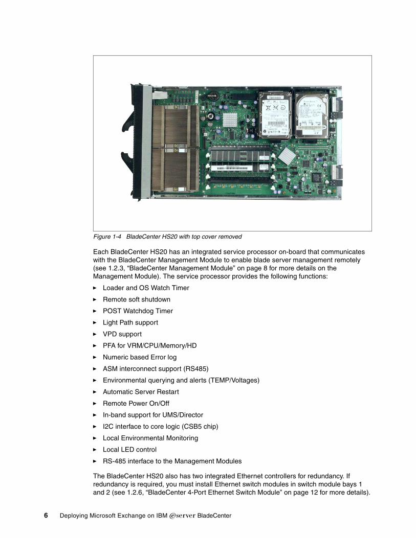
Figure 1-4 BladeCenter HS20 with top cover removed
Each BladeCenter HS20 has an integrated service processor on-board that communicates with the BladeCenter Management Module to enable blade server management remotely (see 1.2.3, “BladeCenter Management Module” on page 8 for more details on the Management Module). The service processor provides the following functions:
� Loader and OS Watch Timer
� Remote soft shutdown
� POST Watchdog Timer
� Light Path support
� VPD support
� PFA for VRM/CPU/Memory/HD
� Numeric based Error log
� ASM interconnect support (RS485)
� Environmental querying and alerts (TEMP/Voltages)
� Automatic Server Restart
� Remote Power On/Off
� In-band support for UMS/Director
� I2C interface to core logic (CSB5 chip)
� Local Environmental Monitoring
� Local LED control
� RS-485 interface to the Management Modules
The BladeCenter HS20 also has two integrated Ethernet controllers for redundancy. If redundancy is required, you must install Ethernet switch modules in switch module bays 1 and 2 (see 1.2.6, “BladeCenter 4-Port Ethernet Switch Module” on page 12 for more details).
6 Deploying Microsoft Exchange on IBM Eserver BladeCenter
Each controller is auto-sensing and will connect at the appropriate rate, even if the transfer rate is 10 Mbps, 100 Mbps or 1000 Mbps. The controller will also set the appropriate duplex state.
The Ethernet controller is capable of providing several teaming options that increase throughput and fault tolerance. In your blade server, a team consists of the two Ethernet controllers to utilize the options below:
Adapter fault tolerance (AFT) Provides automatic redundancy for your Ethernet controllers. You can configure either one of the integrated Ethernet controllers as the primary Ethernet controller. If the primary link fails, the secondary controller takes over. When the primary link is restored to an operational state, the Ethernet traffic switches back to the primary Ethernet controller.
Adaptive load balancing (ALB) Enables you to balance the transmission data flow among the two controllers. ALB also includes the AFT option. You can use ALB with any 100BASE-TX/1000BASE-T switch.
Cisco Fast EtherChannel (FEC) Creates a team of two controllers to increase transmission and reception throughput. FEC also includes the AFT option. You can use FEC only with a switch that has FEC capability.
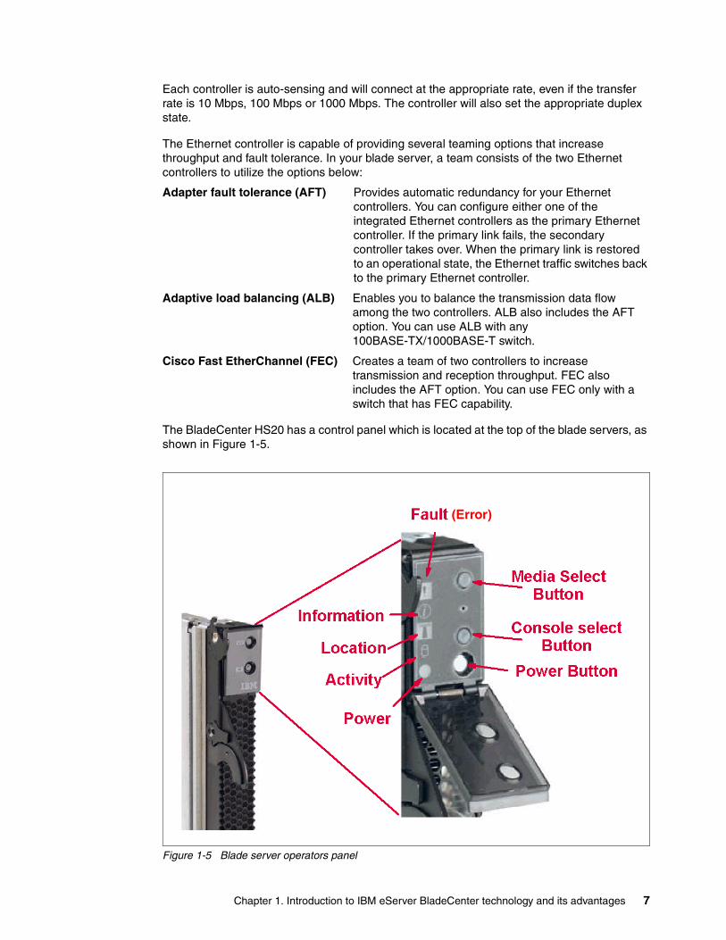
The BladeCenter HS20 has a control panel which is located at the top of the blade servers, as shown in Figure 1-5.
Figure 1-5 Blade server operators panel
(Error)
Chapter 1. Introduction to IBM eServer BladeCenter technology and its advantages 7

Like the IBM Eserver BladeCenter’s media tray, this control panel also has system information LEDs. The only difference is that the blade’s panel also has control switches, which are detailed below.
Media-select button Press this button to associate the CD-ROM drive, diskette drive, and USB port with this blade server. This button lights when the ownership of the CD-ROM drive, diskette drive, and USB port transfers to this blade server.
Blade-error This LED is also known as the blade system-error LED. When this amber LED is on, it indicates a system error has occurred in the blade.
Information When this amber LED is on, it indicates information about a system error for this server has been placed in the BladeCenter System Error log.
Location This blue LED is turned on in response to a programmed condition, or remotely by the system administrator, to aid in blade identification for maintenance. The location LED on the IBM Eserver BladeCenter will be on also. Turn off the location LED after maintenance is complete.
Activity When this green LED is on, it indicates that there is activity in the blade server; this includes hard disk and network activity.
Power-on While the IBM Eserver BladeCenter has AC power, this green LED turns on and stays on when you turn on your blade server.
Console select button Press this button to associate the keyboard, mouse, and video ports with this blade server. This button lights when the ownership of the keyboard, mouse, and video transfers to this blade server.
Power-control button This button is located behind the control panel door. Press this button to manually turn the blade server on or off.
1.2.3 BladeCenter Management ModuleThe BladeCenter Management Module’s primary function is to provide systems management for your IBM Eserver BladeCenter and blade servers, but it does have other important functions such as multiplexing the keyboard/video/mouse (KVM) to provide a local console for the individual blade servers and configuring the BladeCenter unit and switch modules. The Management Module communicates with all of the key components of the IBM Eserver BladeCenter including the switch, power and blower modules, as well as the blade servers themselves. The Management Module detects the presence, absence and condition of each of these components. A picture of the BladeCenter Management Module is shown in Figure 1-6 on page 9.
Note: The power-control button only has effect if the local power control option is enabled via the Management Module.
8 Deploying Microsoft Exchange on IBM Eserver BladeCenter

Figure 1-6 BladeCenter Management Module
The Management Module has a standard RJ45 connector for a 10/100MB Ethernet remote console connection, as well as two PS/2® connectors for keyboard, mouse and a 15-pin D-shell connector for video which are provided for the local console. Although the connectors for the keyboard and mouse are PS/2 type connectors, these devices are routed to a USB bus, enabling them to be switched between blades.
The Management Module will retrieve and monitor critical information about the chassis and blade servers such as temperature, voltages, power supply, memory, fan and HDD status; this information will then be fed into an error and status log.
The manageability functions of the IBM Eserver BladeCenter are accessible via a Web GUI that is contained in the Management Module. This GUI allows you to view the status of, and control each blade server, which includes shutting down and restarting.
1.2.4 BladeCenter 1200W Power Supply Module The standard BladeCenter chassis will ship with two 1200W Power Supply Modules, but, depending on the configuration of your IBM Eserver BladeCenter, you may require all four power modules. The standard two power modules provide power for the following components:
� Blade slots 1 through 6
� Blowers
� Management modules
� Switch modules
� Media tray
Note: The operating system in each blade must provide USB support for the blade server to recognize and make use of the keyboard and mouse.
Chapter 1. Introduction to IBM eServer BladeCenter technology and its advantages 9

Figure 1-7 BladeCenter 1200W Power Supply Module
Power Modules 3 and 4 are required to provide power to blade slots 7 to 14. Figure 1-8 on page 11 shows how power is distributed by each power module. One power module is capable of providing enough power in the event of a power module failure. Power module 2 provides redundancy for power module 1 and power module 4 does the same for power module 3, although these power modules will effectively share the load under normal operating conditions. Supported configurations require either two or four power supplies, which is why when you order the optional BladeCenter 1200W Power Supply Module kit, you will receive two of the power modules.
BladeCenter power module upgrade guidelinesThis section contains information that will help you determine whether you need to upgrade the power modules in your IBM Eserver BladeCenter unit when installing IBM Eserver BladeCenter HS20 blade servers.
As of the date of this printing, three BladeCenter power module options are available: IBM BladeCenter 1200W Power Supply Module (part number 48P7052), IBM BladeCenter 1200W to 1400W Power Supply Upgrade Kit (part number 90P0197), and IBM BladeCenter 1800W Power Supply Module (part number 13N0570). Go to http://www.ibm.com/pc/compat/ for information about ordering these options. Obtain and use the Technical Update with your BladeCenter and blade server documentation for future reference.
Important: Nonredundant power is not supported in BladeCenter products. Power modules must always be present in power bays 1 and 2. When any blade server or option is in blade bay 7 through 14, power modules must be present in power bays 1 and 2, as well as in power bays 3 and 4. If a power module fails or an ac power failure occurs, BladeCenter units configured for redundant power operation, as described in this document, will operate in a nonredundant mode, and the blower modules will run at full speed. You must replace the failing power module or restore ac power as soon as possible to regain redundant power operation and to reset the blower modules to their normal operating speed.
10 Deploying Microsoft Exchange on IBM Eserver BladeCenter

The Technical Update can be obtained from the following URLs:
http://www-1.ibm.com/support/docview.wss?uid=psg1MIGR-53353ftp://ftp.software.ibm.com/pc/pccbbs/pc_servers_pdf/13n0308.pdf
Figure 1-8 MidPlane power connector
1.2.5 BladeCenter blowers The IBM Eserver BladeCenter ships with both hot-swap blowers which are required to provide adequate cooling; these blowers provide a total airflow of approximately 325 CFM; however, each blower will run at approximately 50% under normal conditions. If one blower fails, the other blower is capable of providing enough cooling for the entire chassis. However, the failed blower should be replaced within 48 hours. The speed of the blowers is controlled via the Management Module which receives signals from thermal monitors located in critical locations. There are two scenarios which will cause both blowers to function at full speed:
� The Management Module fails and the redundant module is not present.
� One of the power supply modules fails.
In Figure 1-9 on page 12, you can see that there are four fins which are currently closed since the blower is not operational. When operational, the blower draws the air from the front to the rear. Each blower also has an LED which will light up in the event of an error.
Chapter 1. Introduction to IBM eServer BladeCenter technology and its advantages 11

Figure 1-9 BladeCenter Blower Module
1.2.6 BladeCenter 4-Port Ethernet Switch ModuleThe Ethernet Switch Module (Figure 1-10 on page 13) has several purposes; in addition to providing network connectivity for the IBM Eserver BladeCenter and blades, it also provide interconnectivity between the blades and management modules. The Ethernet switch module does not come standard with the IBM Eserver BladeCenter; it is available for purchase as an option but it is required in most cases and should be installed in switch bay 1. This module is a fully functional Ethernet switch which has four 1000 Mbps ports externally, two internal 10/100 Mbps links to the management modules and fourteen 1000 Mbps links to the blades, which are also internal. Two of these switch modules can be added for redundancy. The switch module is configured via the Management Module.
12 Deploying Microsoft Exchange on IBM Eserver BladeCenter

Figure 1-10 BladeCenter 4-Port Ethernet Switch Module
In Figure 1-10, the two LEDs at the top of the switch module indicate power-on and Ethernet switch errors. There are also LEDs next to each port which indicate Ethernet link and activity.
1.2.7 BladeCenter Layer 2-7 GbE Switch ModuleThe Ethernet Switch Module (Figure 1-11 on page 14) has several purposes. In addition to providing network connectivity for the BladeCenter unit and blade servers, it also provide interconnectivity between the blades and Management Modules. The Layer 2-7 GbE Switch Module does not come standard with the IBM Eserver BladeCenter. It is available for purchase as an option, but it is required in most cases and should be installed in switch bay 1. This module is a fully functional Ethernet switch that has four 1000 Mbps ports externally, two internal 10/100 Mbps links to the Management Modules and 14 1000 Mbps links to the blades, which are also internal. Two of these switch modules can be added for redundancy. The switch module is configured via the Management Module. For a more in-depth look at Layer 2-7 Switching, refer to the Redpaper IBM ^BladeCenter Layer 2-7 Network Switching, REDP3755.
Chapter 1. Introduction to IBM eServer BladeCenter technology and its advantages 13

Figure 1-11 BladeCenter 4-port Ethernet Switch Module
In Figure 1-11, the two LEDs at the top of the switch module indicate power-on and Ethernet switch error. There are also LEDs next to each port that indicate Ethernet link and activity.
1.2.8 BladeCenter 2-Port Fibre Channel Switch ModuleIf you require Fibre Channel connectivity for your IBM Eserver BladeCenter, there are two things you are required to do:
1. Install the IBM HS20 Fibre Channel Expansion Card in each blade that requires an FC connection.
2. Install one BladeCenter 2-Port Fibre Channel Switch Module (Figure 1-12 on page 15) in switch bay 3. If redundancy is required, a FC switch module must be installed in switch bay 4.
Each port on the FC switch module is capable of supporting transmission speeds of either 1 or 2 Gbps and must auto-negotiate to match the speed of any connected devices. A Small Form factor Pluggable (SFP) transceiver is required to populate these ports; these SFP transceivers are hot pluggable. The FC switch module is also managed through the Management Module.
14 Deploying Microsoft Exchange on IBM Eserver BladeCenter

Figure 1-12 BladeCenter 2-Port Fibre Channel Switch Module
The storage options for the IBM Eserver BladeCenter are covered in Chapter 3, “Storage options for the BladeCenter” of the Redpaper The Cutting Edge: IBM Eserver BladeCenter, REDP3581.
1.2.9 BladeCenter Acoustic Attenuation ModuleIn environments where it is important to minimize sound emissions, there is a noise reduction option available that can be installed on the rear of the IBM Eserver BladeCenter. This option is called the BladeCenter Acoustic Attenuation Module (acoustic module or muffler). The acoustical noise emissions for a single BladeCenter unit configured with 14 IBM Eserver BladeCenter HS20 servers are:
� 7.4 bels (operating)
� 7.4 bels (idling)
The acoustical noise emissions for a single BladeCenter unit with a BladeCenter Acoustic Attenuation Module option installed and configured with 14 IBM Eserver BladeCenter HS20 servers are:
� 6.9 bels (operating)
� 6.9 bels (idling)
For visibility purposes, the system LEDs on the rear of the BladeCenter unit have been replicated on the acoustic module, as these are covered when this option is fitted. The acoustic module also fully covers the blower modules and partly covers the other modules installed.
Note: The BladeCenter Acoustic Attenuation Module requires approximately eight inches between the rear of the IBM Eserver BladeCenter and the rack door. For this reason, the NetBay 42 Enterprise Rack Cabinet should be used when installing the IBM Eserver BladeCenter with this option.
Chapter 1. Introduction to IBM eServer BladeCenter technology and its advantages 15
1.3 The advantages of IBM eServer BladeCenterUnlike typical server architecture which scales up, the BladeCenter allows for the scale out approach, yet balances performance and density. In this section, we identify the advantages of the BladeCenter for your business, such as:
� Systems management
� High density computing
� Redundancy
1.3.1 Systems managementThe systems management component for the BladeCenter is the combination of IBM Director, the Web interface and Rapid Deployment Manager (RDM). With these tools, you can reduce system outages, increase IT personnel productivity and reduce support costs.
IBM DirectorIBM Director is a comprehensive workgroup hardware manager designed for use with IBM Eserver xSeries servers, PCs, notebooks and now IBM Eserver BladeCenter.
IBM Director provides a comprehensive view of the xSeries servers.
� Remote access to the server regardless of its status
� Resetting or cycling of the server
� Server inventory, AssetID, blade slot numbers utilized
� Monitoring and setting thresholds on the server events, including PFA
� Flash BIOS
� Monitoring and identifying potential performance bottlenecks
IBM Director allows you to reduce system outages, increase IT personnel productivity and reduce support costs.
These goals can be accomplished by:
� Monitoring server health
� PFA - Predictive Failure Analysis®
� Integration with enterprise system management environments
Monitoring server healthBy setting thresholds on components within IBM Director, you can monitor the following:
� Operating system load
� POST time-out
� Voltage
� Temperature
PFA - Predictive Failure AnalysisSetting alerts on disk, memory and processors via PFA allows you to identify imminent component failure. PFA can monitor the following:
� Processors
� Memory
16 Deploying Microsoft Exchange on IBM Eserver BladeCenter

� Fans
� Power supplies
� SCSI HDDs
Integration with enterprise system management environmentsIBM Director agents should be installed on each of the blade servers as this allows system management of the blades and also provides the advanced management capabilities of the xSeries servers to be accessed from such products as:
� Tivoli Enterprise™ and Tivoli Netview
� Computer Associates CA Unicenter TNG
� HP OpenView
� Microsoft SMS
� BMC Patrol
� NetIQ
This is an important consideration for organizations who have already spent time, money and resources on existing system management tools.
Web interfaceThe Web interface allows you to configure and remotely manage your IBM Eserver BladeCenter via a browser; this is built into the Management Module.
Supported browsers and required components are:
� Microsoft Internet Explorer 4.0 Service Pack 1, or later
� Netscape Navigator 4.72, or later (version 6.0 is not supported)
� Java™-enabled Web browser
� Support for JaveScript 1.2 or later
� HTTP 1.0, or later
� Minimum display resolution 800*600 pixels and 256 colors
The Management Module Ethernet port either receives a DHCP assigned address within two minutes of connecting to the LAN or it defaults to the following IP address 192.168.70.125 with a subnet address of 255.255.255.0. The default hostname is MMxxxxxxxxxxxx where xxxxxxxxxxxx is the MAC address.
Note: The Web interface does not support double-byte character set languages (DBCS).
Note: If multiple IBM Eserver BladeCenters are to be configured, only one can be assigned the default IP address of 92.168.70.125, otherwise IP address conflicts will occur.
If your DHCP server is not on the same subnet as the BladeCenter Management Module console, DHCP traffic needs to be allowed to traverse the router to the Management Module console to receive an DHCP assigned address, or IBM Director Server needs to be on the same subnet as the IBM Eserver BladeCenter.
Chapter 1. Introduction to IBM eServer BladeCenter technology and its advantages 17

The Web interface allows you to manage and check the status of each of the modules and blade servers. Below is a list of the functions and sub-functions available.
� Monitor
– System status
– Event log
– Vital product data
� Blade Tasks
– Power/restart
– Firmware update
– Configuration
� Switch tasks
– Power/restart
– Management
� MM console (Management Module)
– General settings
– Login profiles
– Alerts
– Network interface
– Network protocols
– Security
– Configuration file
– Fireware update
– Restore defaults
– Reset MM
� Log off
RDM - Rapid Deployment ManagerThis powerful tool allows you to deploy system images to the blade servers from the administrator's console.
RDM supports the following environments:
� Windows® 2000
� Windows 2000 Advanced Server
The advantages of Rapid Deployment Manager are:
� Rapid deployment of Operating System image to the destination server
� Hot-spare blade option, “Hot-spare blades” on page 22.
1.3.2 High density computingAs data centers have grown with the proliferation of Wintel servers over recent years, it is important to note that rack space and floor space can be more efficiently taken up with the use of blade servers. A fully populated 42U rack is capable of holding six IBM Eserver BladeCenters and 84 dual processor blade servers, for a total of 168 CPUs per rack. This is
18 Deploying Microsoft Exchange on IBM Eserver BladeCenter

twice the current density of a non-blade server. The IBM Eserver BladeCenter supports a minimum of one 4 port 1 GB Ethernet switch for up to fourteen blade servers. A total of four switch modules can be utilized within the IBM Eserver BladeCenter. This can be a combination of either Fiber Channel or Ethernet.
We recommend the use of blade servers for the following situations:
� Space constrained environments
� WebSphere®
� Linux clusters
� Web caching
� Collaboration applications (Lotus® Notes®, Microsoft Exchange and Citrix)
� Dynamic Web serving - Load balancing
� Firewall
� Telecommunications
� Active directory services
� Scientific and technical computing
These applications are typically processor and memory intensive, and so lend themselves to the scale out option rather then the scale up option. The scale out option is where the strength of the IBM Eserver BladeCenter becomes obvious. Due to the highly scalable range of components available with the BladeCenter unit, the blade server has a huge market.
Figure 1-13 Scale up versus scale out
Attractive cost savings are also possible where a large number of rack installed servers are required. These savings run from power usage, to hardware procurement (due to not duplicating components), through to server management. Table 1-1 on page 20 demonstrates the input voltage required for different servers providing the same number of
Chapter 1. Introduction to IBM eServer BladeCenter technology and its advantages 19

CPUs. It also shows the heat output in BTUs, which can affect the cooling of your computer room and other equipment within the computer room.
Table 1-1 Power and BTU usage
Deploying an IBM Eserver BladeCenter is far simpler than deploying 14 1U servers and the associated cables. A single IBM Eserver BladeCenter only requires a KVM cable, one power cable, one Ethernet cable and a single system management cable. Even with a redundancy of these components, cabling can be reduced by eighty-three percent (see Table 1-2 for a typical example).
Table 1-2 Cable utilization
The IBM Eserver BladeCenter is not intended to replace any of the xSeries suite of products, but rather to provide additional configuration options.
1.3.3 RedundancyWe all know failures occur occasionally; we also know that redundancy of key components increases system availability. Although previously, it was expensive to purchase redundant options for individual servers, the high availability features found in conventional xSeries rack servers have also been included within IBM Eserver BladeCenter. These features include:
� Hot-spare blades
� Processor
Number of Servers
Processor Maximum load watts
BTU
IBM x330 4MX 14 Pentium® III 1.4GHz 3080 10502
IBM x335 14 Xeon 2.4GHz 4760 16231
IBM x342 - Dual Power 14 Pentium III 1.4GHz 5250 19821
IBM x345 - Dual Power 14 Xeon 2.4GHz 7000 23870
IBM Eserver BladeCenter
14 Xeon 2.4GHz 2500 8530
Note: The IBM Eserver BladeCenter in Table 1-1 is utilizing the onboard IDE controller.
1U Solution (2 - 42U Racks)
IBM Eserver BladeCenter Solution
(2 - 42U Racks)
Power 84 12
Ethernet 168 48
KVM 84 6 (ACT)
Switch 6 (boxes) 1 (ACT)
KVM interconnect 5 0
Management connect 84 6
Total 431 73
20 Deploying Microsoft Exchange on IBM Eserver BladeCenter

� Memory protection
� Disk mirroring
� MidPlane
� Hot-swap power and cooling modules
� Switch modules
Figure 1-14 Module location on the rear of the IBM Eserver BladeCenter
Table 1-3 outlines which components can be redundant, hot swap, PFA or have Light Path diagnostics.
Chapter 1. Introduction to IBM eServer BladeCenter technology and its advantages 21

Table 1-3 Redundant, Hot-swap, PFA or Light Path
Hot-spare bladesMidPlane supports hot-spare blade servers; this operates in the same fashion as the hot-spare drive. By creating events within IBM Director, you can deploy an operating system to a hot-spare blade server automatically.
ProcessorIn a dual processor blade server, if a CPU fails, the following steps are taken by the system.
1. Force failed processor offline
2. Automatically re-boot server
3. Generate alerts
4. Continue operating with the working processor
MemoryThere are four memory slots; memory must be installed in matching pairs. The following redundancy options are available:
� Chipkill™ ECC - provides correction for up to 4 bits per DIMM
� Memory hardware scrubbing - corrects soft memory errors automatically
� PFA - Creates alerts of imminent failure
Redundant Hot Swap PFA Light Path
Blade Yes Yes No Yes
Processor Auto Recovery No Yes Yes
Memory ECC w/Auto down size
No/Tool less Yes Yes
Power Supplies Yes Yes Yes Yes
Cooling Fans Yes Yes Yes Yes
Management Module
TBD TBD TBD TBD
Switch Module Yes Yes TBD TBD
Backplane Yes No No No
Front Plane /Media Tray
No Yes No No
CD ROM Drive No No No No
Floppy Drive No No No No
Hard Drive Raid Only with Blade Storage
expansion (HS SCSI drives)
Yes Yes
Power Cable Yes Yes No No
22 Deploying Microsoft Exchange on IBM Eserver BladeCenter

Disk mirroringRefer to Chapter 3, “Storage options for the BladeCenter” of the Redpaper The Cutting Edge: IBM Eserver BladeCenter, REDP3581 for hardware and software mirroring options of IDE and SCSI disks.
MidPlaneThe middle plane provides connectivity between the blades and the modules at the rear of the BladeCenter unit. There are two connections on each blade server to independent middle planes for redundancy.
Hot-swap power and cooling modulesBy sharing fans, power supplies, cables and other components within a BladeCenter unit and installing the redundant options for these, your organization can reduce the number of points of potential failure, thus increasing system availability.
BlowersTwo hot-swap blowers are standard in the IBM Eserver BladeCenter; the blower speed varies depending on the temperature. A failed blower needs to be replaced within 48 hours.
Figure 1-15 Acoustic Attenuation Module
PowerThe IBM Eserver BladeCenter comes with two 220 volt 1200 watt hot-swap power modules in power bays 1 and 2. Table 1-4 outlines the power module bays and their functions.
Note: An Acoustic Attenuation Module can be fitted to reduce noise.
Shaft
Acoustic muffler
Lockinghandle
Chapter 1. Introduction to IBM eServer BladeCenter technology and its advantages 23

Table 1-4 Power module bays
Cabling modulesThe IBM Eserver BladeCenter is capable of managing four switch modules of either Ethernet or Fibre, the minimum requirement being a single Ethernet switch.
EthernetTwo hot-swap 1 GB Ethernet four port switch models can be installed in switch module bays 1 and 2.
FibreTwo hot-swap Fibre channel network interface switch modules can be placed in switch module bays 3 and 4.
Power module bays
Power module function
1 Provides power to all the BladeCenter modules in server bay slots 1-6.
2 Redundancy for Power module bay 1.
3 Provides power to all the BladeCenter modules in server bay slots 7-14.
4 Redundancy for Power module bay 3.
Note: A blade server in bay 6 with a SCSI storage expansion option requires a power module in power module bays 3 and 4 to support the SCSI storage expansion.
Note: The IBM Eserver BladeCenter also includes a hot-swap media tray, which includes the CD-ROM and floppy drive.
24 Deploying Microsoft Exchange on IBM Eserver BladeCenter

Chapter 2. Planning and prerequisites for Microsoft Exchange
In this chapter, we will review the hardware and software requirements you will need for the installation of Microsoft Exchange 2000.
2
© Copyright IBM Corp. 2002, 2003. All rights reserved. 25
2.1 Typical installation of BladeServerThe version of Microsoft Exchange we will install onto the BladeServer is Microsoft Exchange 2000 Enterprise Edition. The operating system is Microsoft Windows 2000 Advanced Server.
2.1.1 Differences between Microsoft Exchange versionsHere are the differences between the Microsoft Exchange versions:
Microsoft Exchange 2000The features of Microsoft Exchange 2000 are as follows.
� Individual databases are limited to a maximum size of 16 gigabytes.
� Only one storage group can be created on a server.
� Only one private information store and one public information store can be created on a server.
� Microsoft Exchange 2000 Standard Edition cannot be clustered on Microsoft Cluster Server Service.
� Microsoft Exchange 2000 Standard Edition cannot be used as a front-end server in a front end/back end configuration.
Microsoft Exchange 2000 Enterprise EditionThe features of Microsoft Exchange 2000 Enterprise Edition are as follows.
� Database size is limited only by hardware (with a maximum size of 16 terabytes.)
� Up to four storage groups can be created onthe server.
� Up to five information stores can exist in each storage group.
� Microsoft Exchange 2000 Enterprise Server can be clustered on the Microsoft Cluster Server Service.
� Microsoft Exchange 2000 Enterprise Server can be implemented as a front-end server for front-end/back-end configuration.
� The X.400 Connector is included.
2.1.2 Fix levelsAt the time of writing, we used the latest application and operating systems and service packs, Microsoft Exchange 2000 Service Pack 3 and Microsoft Windows 2000 Server Service Pack 3, which is required for IBM Eserver BladeCenter.
There are certain facts about Service Pack 3 which should be considered:
� Microsoft requires that you install Windows 2000 SP2® or SP3 on your server before you install Microsoft Exchange 2000 SP3. Since this is an IBM Eserver BladeCenter installation, Service Pack 3 is mandatory.
� Microsoft supports running Microsoft Exchange 2000 SP3 on Windows 2000 SP3 servers in deployments with Windows .NET Server domain controllers.
� Microsoft does not support running Microsoft Exchange 2000 SP3 on computers running Windows .NET server operating systems.
� You must have Microsoft Exchange Full Administrator permissions at the organization or the administrative group level to install Microsoft Exchange 2000 SP3.
26 Deploying Microsoft Exchange on IBM Eserver BladeCenter

2.1.3 Hardware prerequisites for Microsoft Exchange 2000Listed in this section are the hardware prerequisites for Microsoft Exchange 2000.
Minimum configurationThe minimum hardware requirements for running Microsoft Exchange follows:
� Pentium 166 MHz
� 128 MB of RAM
� NTFS partition with 4 GB or more
This has to be listed as an absolute minimum.
IBM Eserver BladeServer used in our labThe IBM Eserver BladeServer used for this installation had the following elements:
� One 2.0 GHz processor
� Two 40 GB IDE hard drives
� 512 MB of RAM
� Gigabit Ethernet interfaces
2.1.4 Software prerequisites for Microsoft ExchangeListed in this section are the software prerequisites for Microsoft Exchange 2000:
� Microsoft Windows 2000
� SMTP needs to be installed, included in IIS
� NNTP needs to be installed, included in IIS
� DNS
� Computer must be a member of a domain
� Active directory must be installed and configured for Microsoft Exchange
2.1.5 Scenario of IBM eServer BladeCenter running Microsoft ExchangeSince the IBM Eserver BladeCenter by default has one or two IDE disks internally, it is not the ideal disk subsystem on which to run Microsoft Exchange. There are two alternatives for this. The first alternative is to install the SCSI option. The other alternative is to install the Fibre option and connect to a SAN. The second option is probably the best. If the two IDE disks are used, mirroring the disks in Windows 2000 is recommended.
When you use only one blade server with the internal IDE disks, the disk subsystem is the bottleneck for the installation. This configuration will only give you 40 GB of total disk space if you mirror the disks, minus the operating system, applications, Microsoft Exchange 2000 server and similar items. If we calculate that each user has a limit of 50 MB per mailbox, this allows you about 600 users.
Chapter 2. Planning and prerequisites for Microsoft Exchange 27

The rest of the hardware in the blade server is capable of handling a much larger number of users. For example:
� One blade server with Windows 2000, running DNS, DHCP, AD, WINS, etc.
� One blade server running Windows 2000 configured with:
– 2 GB of RAM
– Two XEON 2.0 GHz processors
– Fibre channel option with enough disk to hold the mailboxes and several different partitions
– 50 MB per mail user
This configuration could potentially handle approximately 4500 users
28 Deploying Microsoft Exchange on IBM Eserver BladeCenter

Chapter 3. Suggested configurations and considerations
In this chapter, we discuss the different settings and tuning parameters and how to install Microsoft Windows 2000 and Microsoft Exchange 2000.
3
© Copyright IBM Corp. 2002, 2003. All rights reserved. 29

3.1 Setup and tuningIn this section, we will discuss the following:
� How to set up and prep the machine for installation
� How to configure Windows 2000 for Microsoft Exchange
� How to change settings in Microsoft Exchange for tuning and performance
3.1.1 How to prepare the machineFirst, we discuss how to prepare the machine or system you will use for installing Microsoft Exchange. There are a few settings in the server that can improve server performance and uptime:
� There are two Broadcom network cards in each blade server, each one connected to one network switch. Even if you do not have two network switches in your IBM Eserver BladeCenter, leave the unused network card enabled. Install both cards in Windows 2000 and disable it in the operating system. In the future, if you add another switch, you do not have to reboot the blade server and change the settings in the BIOS (see Figure 3-1).
Figure 3-1 Settings for Ethernet adapters
� Regarding the startup sequence, if the machine was installed over the network with RIS, you probably do not need to boot from a diskette or CD-ROM and can disable these in the boot order. If you plan to use RDM, you should enable the Wake On LAN setting (Figure 3-2 on page 31) to be able to remotely start a blade server that has been turned off.
30 Deploying Microsoft Exchange on IBM Eserver BladeCenter
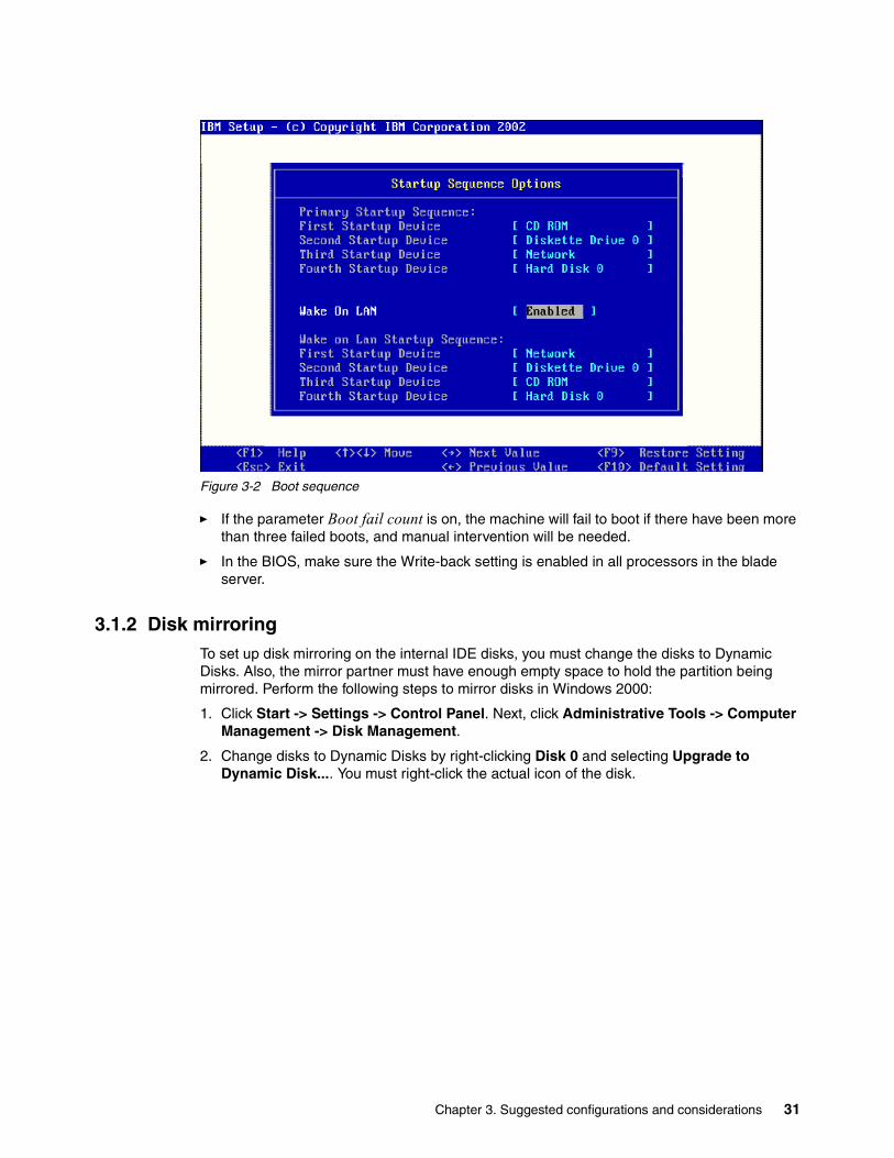
Figure 3-2 Boot sequence
� If the parameter Boot fail count is on, the machine will fail to boot if there have been more than three failed boots, and manual intervention will be needed.
� In the BIOS, make sure the Write-back setting is enabled in all processors in the blade server.
3.1.2 Disk mirroringTo set up disk mirroring on the internal IDE disks, you must change the disks to Dynamic Disks. Also, the mirror partner must have enough empty space to hold the partition being mirrored. Perform the following steps to mirror disks in Windows 2000:
1. Click Start -> Settings -> Control Panel. Next, click Administrative Tools -> Computer Management -> Disk Management.
2. Change disks to Dynamic Disks by right-clicking Disk 0 and selecting Upgrade to Dynamic Disk.... You must right-click the actual icon of the disk.
Chapter 3. Suggested configurations and considerations 31

Figure 3-3 Upgrading to Dynamic Disk
3. Select the disk you want to upgrade and click OK. You will see a window similar to Figure 3-3.
Figure 3-4 Upgrading the disk
4. You will get a response showing the disks about to be upgraded (Figure 3-4). Click Upgrade.
5. Click Yes to respond to the question Are you sure you want to upgrade?.
6. Click Yes to respond to the question Do you want to continue this operation?.
7. Click OK to respond to the statement A reboot will take place to complete the upgrade process.
8. When you log on after the reboot, the machine will have to rebooted again.
32 Deploying Microsoft Exchange on IBM Eserver BladeCenter

9. After the second reboot, repeat Step 1 to start Disk Management. You will see a window similar to Figure 3-5.
Figure 3-5 Adding the mirror
10.Right-click the partition you want to mirror and click Add Mirror.
11.Select the disk you want to mirror the data to and click Add Mirror.
12.When the mirror has started, you will get a response similar to the one shown in Figure 3-6.
Figure 3-6 Setup of mirroring finished
13.Click OK.
For more information on how to set up the boot.ini, see Microsoft Windows 2000 documentation.
Chapter 3. Suggested configurations and considerations 33

3.1.3 Using CMDCONS (Recovery Console)Follow the steps below to install the recover console on the Windows Server to aid in troubleshooting.
1. Insert the Windows 2000 Server CD into the CD-ROM drive.
2. From the Start menu, click Start -> Run, type CMD and click OK.
3. Change to the CD-ROM drive and type \i386\winnt.exe /cmdcon.
4. Click Yes to install the Recovery Console from the Windows 2000 Setup window.
Figure 3-7 Recovery Console setup
5. Click OK.
The recovery console has been inserted into the boot.ini file and will appear as a choice during startup.
3.1.4 How to partition disks in Microsoft ExchangeFollowing are some recommendations on how to partition disks in Microsoft Exchange 2000 for a mailbox and public folders server:
� Raid 1 for operating system, Microsoft Exchange binaries
� Raid 1 for Microsoft Exchange logs
� Raid 1 for operating system swap
� Raid 5 for Microsoft Exchange database files
These partitions should preferably be located on different physical drives or arrays. Note that you are unable to perform the above recommendations on the blade server if using the internal IDE disks. If using the internal IDE disks in the blade server, the best thing would be to mirror the drives within Windows 2000. However, the recommended path would be to place the operating system on the internal disks, either IDE or SCSI, and place the Microsoft Exchange files on a SAN through the optional HS20 Fibre Channel Expansion Card.
34 Deploying Microsoft Exchange on IBM Eserver BladeCenter

3.2 Tuning and performanceIf you compare Microsoft Exchange 2000 with Microsoft Exchange 5.5, the tuning in Microsoft Exchange 2000 is very dynamic except for the hardware and operating system settings that Microsoft Exchange itself does not influence. There are still things that can be done to enhance performance and availability.
3.2.1 Hardware and software settingsPerform the following:
� Ensure that the BIOS in the system is configured for maximum performance.
� Update BIOS, service packs and drivers for the machine.
� Configure Microsoft Exchange by placing the different components in the best array or disk for that particular component.
� Do not place stores and log on the same disk or array.
� Fill out your storage groups to maximum before creating a new group; this saves memory.
� If the Microsoft Exchange server has 1GB of memory or more, you need to add the /3GB switch to the boot.ini.
� Defragment disk partitions to make data more contiguous.
� Run ESEUtil from the Microsoft Exchange CD-ROM to defragment databases. Use the /p switch to defragment the database in another location instead of rebuilding it in place.
3.2.2 Registry key settingsThis section mainly addresses the setup of larger corporations with large numbers of users. For example, if you are running multiple servers, a mix of Microsoft Exchange 5.5 and Microsoft Exchange 2000 servers or message connectors, you should consider changing some of these parameters. Be careful when modifying the registry.
Message Transfer Agent TuningIn scenarios where only Microsoft Exchange 2000 servers exist in an organization, the MTA does not perform any processing and therefore, does not need to have its performance tuned. However, when you are using both Microsoft Exchange 5.5 and Microsoft Exchange 2000, the MTA is used for all intra-site communications, and possibly, between sites if site connectors using remote procedure calls (RPCs) or X.400 connectors are deployed. The key and its parameters follow:
HKEY_LOCAL_MACHINE\System\CurrentControlSet\Services\MSExchangeMTA\Parameters
DB data buffers per objectThis value represents the number of database server buffers configured for each database object. More buffers require more memory, but make it less likely for a database object to be rolled out to disk because of a lack of buffer space.
� Default setting: 0x3
� When to change: adjust if this MTA communicates with multiple Microsoft Exchange 5.5 servers either within a site or between sites. Additionally, you should tune if a legacy messaging connector is homed on this server.
� Recommend setting: 0x6
Chapter 3. Suggested configurations and considerations 35

Dispatcher threadsThis value represents the number of MTA Dispatcher threads, which are responsible for the processing of messages. This is multiplied by three for the three subtypes (Router, Fanout, Result) of Dispatcher thread.
� Default setting: 0x1
� When to change: adjust if this MTA communicates with other Microsoft Exchange 5.5 servers. Additionally, consider tuning if more than five Microsoft Exchange 5.5 servers exist on the site, or if groups (that is, distribution lists) are heavily used.
� Recommend setting: 0x3
Kernel threadsThis value represents the number of platform threads that handle the Presentation and Session level of the Open Systems Interconnection (OSI) stack. These threads are at the heart of MTA message processing.
� Default setting: 0x1
� When to change: adjust if this MTA communicates with other Microsoft Exchange 5.5 servers using RPC over slow or highly latent network connections.
� Recommend setting: 0x3 is the standard recommendation. 0x8 is recommended if the Microsoft Exchange 2000 MTA belongs to a site containing more than 15 Microsoft Exchange 5.5 servers. 0xC (12) is recommended if the Microsoft Exchange 2000 MTA belongs to a site containing more than 30 Microsoft Exchange 5.5 servers.
Max RPC Calls OutstandingThis value represents the maximum number of remote procedure call (RPC) threads. This limits the maximum number of RPC procedure calls that are guaranteed to be processed at one time.
� Default setting: 0x32 (50)
� When to change: adjust if you increase the number of Gateway In/Out threads in the Store.exe process (which is recommended in Microsoft Exchange 5.5 and Microsoft Exchange 2000 co-existence scenarios).
� Recommended setting: 0x80 (128)
MDB usersThis defines the number of distinguished names (DNs) to cache from the directory.
� Default setting: 0x1F4 (500)
� When to change: adjust when your organization contains more than 1500 users. Change the value to one-third the size of the Global Address List, to a maximum of 5000.
� Recommended setting: 0x1388 (5000)
RTS threadsThis stands for Reliable Transfer Service threads. This value represents the number of platform threads that handle the RTSE level of the Open Systems Interconnection (OSI) stack.
� Default setting: 0x1
� When to change: adjust if this MTA communicates with multiple Microsoft Exchange 5.5 servers either within a site or between sites.
� Recommended setting: 0x3
36 Deploying Microsoft Exchange on IBM Eserver BladeCenter

TCP/IP control blocksThis value represents the maximum number of concurrent RFC1006 (TCP/IP) connections that are supported. This setting controls the number of buffers available for X.400 connections.
� Default setting: 0x14 (20)
� When to change: adjust if hosting more than one X.400 Connector on the server.
� Recommended setting: ten control blocks for each hosted X.400 Connector, plus one control block for incoming connections.
Transfer threadsThis value represents the number of MTA Transfer threads. This is multiplied by two for the two subtypes (Transfer In, Transfer Out) of Transfer thread.
� Default setting: 0x1
� When to change: adjust if this MTA communicates with multiple Microsoft Exchange 5.5 servers either within a site, or between sites.
� Recommended setting: 0x3
MSExchangeIS Registry Key SettingsWhen messages are received into the MTA from an Microsoft Exchange 5.5 server or legacy gateway, they are handed off to the Store.exe process, and then go to the advanced queuing engine. In environments where many messages are arriving into the MTA simultaneously, it is advantageous to increase the number of processing threads between the Store.exe process and MTA. You can monitor the MTA to Store.exe process queue build-ups using either Performance Monitor or Microsoft Exchange System Manager. The key and its parameters follow:
HKEY_LOCAL_MACHINE\System\CurrentControlSet\Services\MSExchangeIS\server_name\Private-database_guid
Gateway In Threads (REG_DWORD)This defines the number of threads available for retrieving messages from the MTA process into the Store.exe process.
� Default setting: not present, but defaults to 0x1.
� When to change: adjust if this MTA communicates with multiple Microsoft Exchange 5.5 servers or legacy messaging connectors.
� Recommended setting: 0x3
Note: Each of these threads will consume about 1 MB of virtual memory. Further, the actual number of threads created will be this value multiplied by the number of databases. This could be an issue on servers with a large number of private databases. If you have, for example, 10 private databases and increase this parameter and the following parameter from 1 to 3 (a total increase of 4 threads), you will actually create 4 x 10 = 40 threads, which together will consume 40 MB of virtual memory.
Chapter 3. Suggested configurations and considerations 37

Gateway Out Threads (REG_DWORD)This defines the number of threads available for sending messages from the Store to the MTA process.
� Default setting: not present, but defaults to 0x1.
� When to change: adjust if this MTA communicates with multiple Microsoft Exchange 5.5 servers or legacy messaging connectors.
� Recommended setting: 0x3
MTA File DirectoriesOn servers acting as a bridgehead server, you might achieve a better performance if you move the directory to a faster disk array.
1. Stop the Microsoft Exchange MTA Stacks service. To do so, at the command prompt, type the following command:
net stop msexchangemta
2. Edit the following value to reflect the new location for the MTA Database Path:
HKEY_LOCAL_MACHINE \System\CurrentControlSet\ServicesMSExchangeMTA\Parameters\MTA Database Path
3. Explore the new path and create the new directory structure. You may omit the Mtacheck.out folder in the MTA Database Path because the MTA creates this directory automatically.
4. It is important to explore the installation drive and make a backup copy of the Program Files\Exchsrvr\mtadata directory.
5. Explore the original Program Files\Exchsrvr\mtadata directory.
6. On the View menu, click Details. On the View menu, point to Arrange Icons, and then click by Type. Select and then move all of the *.dat files to the new MTA Database path. Change the security for the directory to match that of the original directory.
7. At a command prompt, go to Program Files\Exchsrvr\bin directory.
8. In the new directory, run mtacheck; the task should report Database clean, no errors detected.
9. Start the Microsoft Exchange MTA Stacks service. To do so, at the command prompt type the following command:
net start msexchangemta
38 Deploying Microsoft Exchange on IBM Eserver BladeCenter

Chapter 4. Implementation and configuration of Microsoft Exchange 2000
This chapter will describe how to install and configure Microsoft Exchange and Microsoft Outlook onto an IBM Eserver BladeCenter server.
4
© Copyright IBM Corp. 2002, 2003. All rights reserved. 39

4.1 Installation of Microsoft ExchangeIt is assumed here that this is the first Exchange server installed in a Windows 2000 domain. The installed Windows 2000 server is located on one blade in the IBM Eserver BladeCenter and Microsoft Exchange is located on another one.
4.1.1 Installation of Microsoft Exchange 2000
Preparations to the forestForestPrep extends the Active Directory schema to include Exchange information. In a larger sized Active Directory, this might take considerable time. ForestPrep also prompts you to set the name for your organization during the Exchange 2000 installation in the Active Directory. When you run ForestPrep, it asks for a user which must be a member of Enterprise Admins and Schema Admins; in addition, the account needs administrative rights on the local machine from which you run the ForestPrep application. A good idea is to create a user in the Active directory for this, for example ExAdmin.
1. From the Microsoft Exchange 2000 CD, run setup.exe /ForestPrep.
2. At the Welcome page, click Next.
3. Click I Agree to accept the end user license.
4. Type the license number and click Next. You will see a window similar to Figure 4-1.
Figure 4-1 Running ForestPrep
5. At the Component Selection window, make sure ForestPrep is stated in front of the Microsoft Exchange 2000 installation or component name. Click Next.
6. At the Installation Type window, click to create a new Exchange 2000 Server Organization and then click Next.
7. Type in the name of the organization.
40 Deploying Microsoft Exchange on IBM Eserver BladeCenter
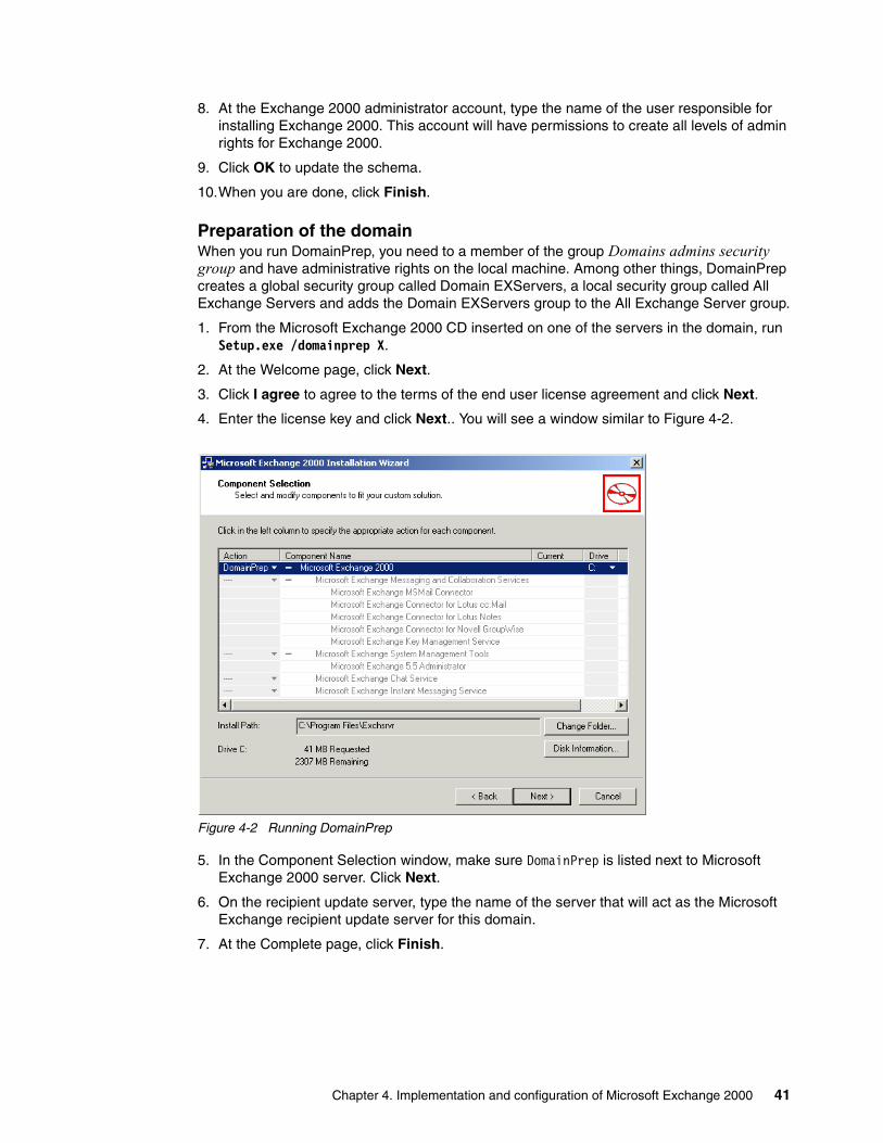
8. At the Exchange 2000 administrator account, type the name of the user responsible for installing Exchange 2000. This account will have permissions to create all levels of admin rights for Exchange 2000.
9. Click OK to update the schema.
10.When you are done, click Finish.
Preparation of the domainWhen you run DomainPrep, you need to a member of the group Domains admins security group and have administrative rights on the local machine. Among other things, DomainPrep creates a global security group called Domain EXServers, a local security group called All Exchange Servers and adds the Domain EXServers group to the All Exchange Server group.
1. From the Microsoft Exchange 2000 CD inserted on one of the servers in the domain, run Setup.exe /domainprep X.
2. At the Welcome page, click Next.
3. Click I agree to agree to the terms of the end user license agreement and click Next.
4. Enter the license key and click Next.. You will see a window similar to Figure 4-2.
Figure 4-2 Running DomainPrep
5. In the Component Selection window, make sure DomainPrep is listed next to Microsoft Exchange 2000 server. Click Next.
6. On the recipient update server, type the name of the server that will act as the Microsoft Exchange recipient update server for this domain.
7. At the Complete page, click Finish.
Chapter 4. Implementation and configuration of Microsoft Exchange 2000 41
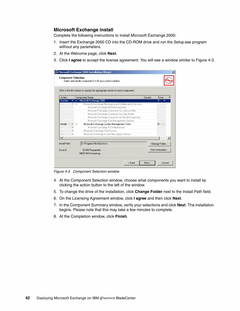
Microsoft Exchange installComplete the following instructions to install Microsoft Exchange 2000:
1. Insert the Exchange 2000 CD into the CD-ROM drive and run the Setup.exe program without any parameters.
2. At the Welcome page, click Next.
3. Click I agree to accept the license agreement. You will see a window similar to Figure 4-3.
Figure 4-3 Component Selection window
4. At the Component Selection window, choose what components you want to install by clicking the action button to the left of the window.
5. To change the drive of the installation, click Change Folder next to the Install Path field.
6. On the Licensing Agreement window, click I agree and then click Next.
7. In the Component Summary window, verify your selections and click Next. The installation begins. Please note that this may take a few minutes to complete.
8. At the Completion window, click Finish.
42 Deploying Microsoft Exchange on IBM Eserver BladeCenter

Applying Service Pack 3 to Microsoft Exchange 2000To install the Microsoft Exchange 2000 Service Pack 3, download the service pack from the following Web site:
http://www.microsoft.com/exchange/downloads/2000/sp3/default.asp
Perform the following steps to allow the service pack to extract and update Microsoft Exchange 2000:
1. Execute the service pack application and choose a directory to unpack it.
Figure 4-4 Unpacking the service pack
2. Click Unzip and when decompression is finished, click OK.
3. From C:\temp\exsp3\server\setup\i386\ directory, run Update.exe.
4. At the Welcome window, click Next. You will see a window similar to Figure 4-5.
Figure 4-5 Updating Exchange
5. On the left side of the window, Update should be stated next to the installed products. Make sure the drive letter to the right of the installed components is correct. Click Next.
6. At the Component Summary window, verify the information is correct. Click Next.
Chapter 4. Implementation and configuration of Microsoft Exchange 2000 43

7. Wait for the installation to complete and then click Finish.
4.1.2 Adding a user to the Microsoft Exchange environmentTo add a user, launch the Active Directory Users and Computers:
1. Click Users.
2. Click Actions -> New -> User.
3. Enter the information about the new user, then click Next.
4. Click Next. In this dialog box, you can select whether this user should have an Exchange mailbox.
5. Click Next and then Finish.
4.1.3 Installation of Microsoft Outlook 2000We will use Microsoft Outlook 2000 from the Microsoft Office 2000 CD in this example. Perform the following steps:
1. Insert the Microsoft Office 2000 CD in the CD-ROM drive. The installation application should auto-start. Wait for the initialization and click Next.
2. Enter the user name and the CD-key.
3. Accept the user agreement and click Next.
4. Click Customize and then click Next.
5. Choose the installation folder or accept the default by clicking Next.
6. Click Next.
7. Only enable Microsoft Outlook 2000 for installation.
Figure 4-6 Installing Outlook 2000
8. The installation start.
44 Deploying Microsoft Exchange on IBM Eserver BladeCenter

9. When the installation has completed, click OK.
Configuration of Microsoft OutlookAfter the installation has been completed, you should have an Outlook icon on the desktop. Perform the following steps:
1. Right-click the Outlook icon and click Properties.
2. Click Add in the dialog box. You will see a window similar to Figure 4-6 on page 44.
Figure 4-7 Microsoft Outlook Setup Wizard
3. Select Microsoft Exchange and click Next.
4. Enter the name of the Exchange server and the name of the user. Click Next.
5. Click Yes or No according to the type of computer you are installing.
6. Click Finish.
Chapter 4. Implementation and configuration of Microsoft Exchange 2000 45

7. The completed installation should look like that shown in Figure 4-8.
Figure 4-8 Setup complete
8. Click Close.
The installation is complete and you should now be able to send and receive messages between users on the Microsoft Exchange server.
46 Deploying Microsoft Exchange on IBM Eserver BladeCenter

Chapter 5. Managing your Microsoft Exchange solution
This chapter provides information on what applications should be used to manage and administer Microsoft Exchange 2000.
These applications are listed as follows:
Microsoft Exchange managerIncluded with Microsoft Exchange is the Microsoft Exchange manager. This is the basic administration application for setting up different tasks in Microsoft Exchange 2000.
MMC ConsoleThe Microsoft Management Console does not by itself provide any management functionality but together with the Microsoft Exchange snap-in, you will get a complete graphical interface to all resources and components of an Microsoft Exchange installation. The MMC gives the administrator the possibility to delegate administrative tasks to other administrators or users, for example, allowing users to create users or public folders.
Active DirectoryUsers are managed through the Active Directory Users and Computers. When Microsoft Exchange is installed, the schema of Active Directory is extended with information for tasks such as creating e-mail addresses, moving mail-boxes and mail-enabling user groups.
Microsoft Operations ManagerThe Microsoft Exchange 2000 Management Pack is part of the Microsoft Operations Manager Application Pack. It includes support for both clustered and non-clustered servers. This Management Pack is a module designed to detect every indication of a potential service interruption and to immediately send an alert to your Microsoft Exchange administrator if a service interruption occurs. Over 1,600 events and performance counters from Microsoft Exchange 2000 and related services can be monitored.
Install this module to contribute to a high-availability Microsoft Exchange 2000 deployment by monitoring select events and counters. This Management Pack also helps facilitate rapid
5
© Copyright IBM Corp. 2002, 2003. All rights reserved. 47

issue resolution by providing critical information and links to relevant Microsoft Knowledge Base articles. In addition, this Management Pack hosts an array of scripts designed to detect other potentially problematic conditions, monitor service and server availability, and track system usage to aid Microsoft Exchange administrators in trend analysis and capacity planning.
Using IBM Director to monitor Microsoft ExchangeOne method to monitor the health of Microsoft Exchange is to use IBM Director to supervise the functions of the machine and the operating system such as memory, processor load, disk space on the Microsoft Exchange server to discover bottlenecks and minimize downtime. Also, by configuring the Director to monitor the different services that Microsoft Exchange starts, you can see whether certain processes stop responding and, if so, automatically restart them or send an alert.
IBM Director V4 includes support for your IBM Eserver BladeCenter server, enabling you to manage, deploy and monitor your system much more efficiently. IBM Director includes features such as self management and proactive and predictive tools, which provide higher levels of availability and reliability.The IBM Director software is made up of three components:
� IBM Director Server
� IBM Director Agent
� IBM Director Console
A different combination of these components is required for each of the hardware groups in your IBM Director environment. The management server must contain all three of these components. IBM Director Console must be installed on the management console or any system from which a system administrator will remotely access the management server. The IBM Director Agent must be installed on each system you intend to manage
Using Tivoli to monitor Microsoft ExchangeAs with IBM Director, you can monitor processes that Microsoft Exchange 2000 uses and monitor the machine itself.
48 Deploying Microsoft Exchange on IBM Eserver BladeCenter

Chapter 6. A brief introduction to Layer 4-7 Switching
This chapter provides a brief overview of how Layer 4-7 Switching works. The goals are to present an alternative to traditional network design and to provide enough background to understand how a Layer 2-7 switch can be beneficial to a network. While this chapter gives a brief overview of the features and benefits of Layer 4-7 Switching, it also mentions the Layer 2-7 GbE Switch Module or GbESM. For a more in-depth look at Layer 4-7 Switching, refer to the IBM Eserver BladeCenter Layer 2-7 Network Switching REDP3755.
6
© Copyright IBM Corp. 2002, 2003. All rights reserved. 49
6.1 Layer 4-7 SwitchingMost networks employ multiple servers without server load balancing. Each server usually specializes in providing one or two unique services. However, a server which provides applications or data that is in high demand can become overutilized. If this happens, network resources can become strained since when the server starts rejecting user requests, the users resubmit the requests for data.This often happens on networks where several other servers are sitting idle with resources available to service users.
Layer 4-7 Switching can harness these available idle servers without additional special equipment such as dedicated load-balancing servers. The term L4-7 is used because these switches are Layer 4 (TCP) aware. These switches use headers and data found at the OSI Layer 7 to accomplish many of their key features. Layer 2 and Layer 3 switches operate on and are aware of Layers 2-3 only.
Layer 4-7 Switching can be used to improve the reliability, scalability, and performance of a wide variety of applications and services. Layer 4-7 isolates the delivery of a service from a user’s point of view from the physical reality of how that service is delivered. A Layer 4-7 switch is aware of the services provided by each server. Based on several load-balancing algorithms, a switch can direct user session traffic to an appropriate server. This means that in addition to using the available resources on otherwise idle servers, resources can be provisioned “on the fly”. This lets network administrators add or subtract to the service delivery capability to react to server failures, meet demands during peak periods and scale back resources once demand is over. All of this happens with no knowledge or participation from the users of that service.
To take advantage of L4-7 Switching, services or applications advertise themselves using normal hostnames such as www.ibm.com® to the outside world. However, DNS resolution will resolve that hostname back to a Virtual IP Address(V_IP) assigned to an L4-7 switch. A service advertised by a V_IP is a Virtual Service. When application requests are sent from users to a V_IP, the L4-7 switch forwards the request to one or more real servers with real IP addresses.
The collection of real servers to which a request for a particular Virtual Service can be sent is called the Virtual Service Pool. By adding real servers to a Virtual Service Pool, the total application delivery throughput can be increased and application delivery times reduced. By moving real servers between Virtual Service Pools, shifting loads and demands between services can be dealt with without having to provision enough servers for each application to meet the peak demands (which would result in many unused servers in off-peak times). Figure 6-1 on page 51 shows how the Layer 2-7 GbE Switch Module installed in BladeCenter could be used to redeploy blades to service a few different applications according to demand.
50 Deploying Microsoft Exchange on IBM Eserver BladeCenter

Figure 6-1 Sample L4-7 configuration
Figure 6-1 shows how services can be deployed using Layer 4-7 Switching. Using the GbESM in the BladeCenter, all server resources can be configured to support all applications, with the GbESM spreading the load among them at all times. As the loads on Sales and Marketing vary throughout the day or week or month, resources are automatically allocated in real time to meet the need.
In this scenario, to provide load balancing for any particular type of service, each server blade in the pool must have access to identical content, either directly (duplicated on each server) or through a back-end network (mounting the same file system or database server).
The GbESM acts as a front end to the servers, interpreting user session requests and distributing them among the available servers. Load balancing in the GbESM can be done in the following ways.
Virtual server-based load balancingThis is the traditional load balancing method. The switch is configured to act as a virtual server and is given a V_IP for each service it will distribute. Each virtual server is assigned a list of the IP addresses (or range of addresses) of the real servers in the pool where its services reside. When the user stations request connections to a service, they will communicate with a virtual server on the switch. When the switch receives the request, it binds the session to the IP address of the best available real server and remaps the fields in each frame from virtual addresses to real addresses. HTTP, IP, FTP, RTSP, IDS, and static session WAP are examples of some of the services that use virtual servers for load balancing.
Filter-based load balancingA filter allows you to control the types of traffic permitted through the switch. Filters are configured to allow, deny, or redirect traffic according to the IP address, protocol, or Layer 4 port criteria. In filtered based load balancing, a filter is used to redirect traffic to a real server group. If the group is configured with more than one real server entry, redirected traffic is load balanced among the available real servers in the group. Firewalls, WAP with RADIUS snooping, IDS, and WAN links use redirection filters to load balance traffic.
Content-based load balancingContent-based load balancing uses Layer 7 application data (such as URL, cookies, and Host Headers) to make intelligent load balancing decisions. URL-based load balancing, browser-smart load balancing, and cookie-based preferential load balancing are a few examples of content-based load balancing.
GbESM
Server Blade
Server Blade
Server Blade
Server Blade
Server BladeSales
Marketing
BladeCenter
SalesMarketing
Sample L4-7 GbESM Configuration
Chapter 6. A brief introduction to Layer 4-7 Switching 51

In the example in Figure 6-1 on page 51, virtual server load balancing is used. The switch has two different V_IPs configured which correspond to each of the services (Sales and Marketing). DNS responds with these V_IPs when these services are requested. The GbESM is also configured for the real IP addresses (R_IPs) which are owned by blades that support requests coming into each V_IP. In this case, all server blades can respond to requests for all services, so each V_IP is assigned the entire set of R_IPs.
A TCP connection consists of a series of packets sent back and forth from two destinations. If packets are misrouted and sent to the wrong destination, the session will slow down due to retransmissions and possibly fail if misrouting continues. Therefore, a Layer 4-7 switch needs to be TCP-aware in the sense that it needs to be able to:
� Identify the beginning of a new TCP connection� Assign that connection to a real server� Make sure that all ensuing packets related to that TCP connection continue to be sent to
the same real server
This requirement is what puts the “Layer 4” in L4-7. The GbESM provides this capability. All arriving packets that are destined to a V_IP are inspected to determine whether they are associated with an existing TCP connection (in which case they are re-directed to the real server already assigned) or whether they are a request to set up a new TCP connection. If the received packet is a request to establish a new TCP connection (a TCP SYN packet), the GbESM will determine the best available server to which to re-direct that request and then do so. The “best available” consideration can be made based upon a number of factors that are beyond the scope of this chapter. It is enough to say that “best available” is based on a consideration of the present health and load of each of the candidate real servers.
This chapter introduces the concepts of Layer 4-7 Switching and how it benefits customers deploying applications on the IBM Eserver BladeCenter. For a more in-depth look at Layer 4-7 Switching, refer to IBM Eserver BladeCenter Layer 2-7 Network Switching, REDP3755. In addition to expanding on the concepts discussed here, this Redpaper is an excellent guide to deploying the GbESM in both Nortel and Cisco networking environments.
52 Deploying Microsoft Exchange on IBM Eserver BladeCenter

Related publications
The publications listed in this section are considered particularly suitable for a more detailed discussion of the topics covered in this Redpaper.
IBM RedbooksFor information on ordering these publications, see “How to get IBM Redbooks” on page 54.
� Installing and Managing Microsoft Exchange 2000 Clusters, SG24-6265
� IBM Eserver BladeCenter Systems Management, REDP3582
� The Cutting Edge: IBM Eserver BladeCenter, REDP3581
� Deploying Lotus Domino on IBM Eserver BladeCenter, REDP3584
� Deploying Citrix MetaFrame on IBM Eserver BladeCenter, REDP3583
� Deploying Apache on IBM Eserver BladeCenter, REDP3588
� Deploying Samba on IBM Eserver BladeCenter, REDP3595
� IBM Eserver BladeCenter Layer 2-7 Network Switching, REDP3755
Other resourcesThese publications are also relevant as further information sources:
� Microsoft Exchange 2000 server design and implementation for Woodgrove Bank - White Paper
� Microsoft Exchange 2000 Internals: Quick tuning guide
� Performance and tuning tip: Defragmenting Exchange 2000 server database
Referenced Web sitesThese Web sites are also relevant as further information sources:
� IBM sites
http://www.pc.ibm.com/us/eserver/xseries/bladecenter_family.html (Main support)
� Microsoft Knowledge Base - Q264075
http://www.microsoft.com/
� Microsoft Knowledge Base - Q262068
http://www.microsoft.com/
� Microsoft Exchange 2000 SP3
http://www.microsoft.com/exchange/downloads/2000/sp3/default.asp
� IBM ServerProven
http://www.ibm.com/pc/compat/
© Copyright IBM Corp. 2002, 2003. All rights reserved. 53
� IBM Eserver BladeCenter - Power Module Upgrade Guidelines
http://www-1.ibm.com/support/docview.wss?uid=psg1MIGR-53353
� IBM Eserver BladeCenter - Power Module Upgrade Guidelines
ftp://ftp.software.ibm.com/pc/pccbbs/pc_servers_pdf/13n0308.pdf
How to get IBM RedbooksYou can order hardcopy Redbooks, as well as view, download, or search for Redbooks at the following Web site:
ibm.com/redbooks
You can also download additional materials (code samples or diskette/CD-ROM images) from that site.
IBM Redbooks collectionsRedbooks are also available on CD-ROMs. Click the CD-ROMs button on the Redbooks Web site for information about all the CD-ROMs offered, as well as updates and formats.
54 Deploying Microsoft Exchange on IBM Eserver BladeCenter

®
INTERNATIONAL TECHNICALSUPPORTORGANIZATION
BUILDING TECHNICAL INFORMATION BASED ON PRACTICAL EXPERIENCE
IBM Redbooks are developed by the IBM International Technical Support Organization. Experts from IBM, Customers and Partners from around the world create timely technical information based on realistic scenarios. Specific recommendations are provided to help you implement IT solutions more effectively in your environment.
For more information:ibm.com/redbooks
Redpaper
Deploying Microsoft Exchange on IBM Eserver
Blazing new trails with IBM Eserver BladeCenter and Microsoft Exchange
Suggested configurations for Microsoft Exchange
Installing and configuring Microsoft Exchange on IBM Eserver BladeCenter
Considering how much data centers have grown with the proliferation of Wintel servers over recent years, it is important to note that rack space and floor space can be more efficiently taken up with the use of the BladeCenter HS20 servers. Attractive cost savings are also possible where a large number of rack installed servers are required, since the equivalent number of 1U servers would be much more expensive.
This IBM Redpaper describes how to set up and configure Microsoft Exchange 2000 on the BladeCenter and provides some pointers on what applications to use to manage the installation. It also describes the functionality of the BladeCenter in this type of environment.
Back cover